Embed Size (px)
Citation preview

OPERATION
&
MAINTENANCE
MANUAL
OPERATION
&
MAINTENANCE
MANUAL
SPOA82 Capacity 7,000 lbs.
TLO7 Capacity 7,000 lbs.
SPO10W Capacity 6,000 lbs
© October 2012 by Rotary Lift. All rights reserved. CO8347 OM20148 Rev. C 10/22/2012LP20197
(Refer to Runway Manufacturer for Runway Capacity)
(500 Series Lifts)
Installer: Please return this booklet to literature package and give to lift owner/operator.
Table of Contents
Safety Instructions ................................................................................................ 2Owner/Employer Responsibilities ....................................................................... 3Operating Instructions (SPO10W) ........................................................................ 4Operating Instructions (SPOA82) ......................................................................... 6Operating Instructions (TLO7) ............................................................................ 8Maintenance Instructions ..................................................................................... 10Trouble Shooting ................................................................................................... 11Lift Lockout/Tagout Procedure ............................................................................. 12Operating Conditions ............................................................................................ 13Approved Accessories .......................................................................................... 13

2
• Daily inspect your lift. Never operate if it malfunctions or if it has broken or damaged parts. Use only qualified lift service personnel and genuine Rotary parts to make repairs.
• Thoroughly train all employees in use and care of lift, using manufacturer’s instructions and “Lifting It Right” and “Safety Tips” supplied with the lift.
• Never allow unauthorized or untrained persons to position vehicle or operate lift.
• Prohibitunauthorizedpersonsfrombeinginshopareawhileliftisinuse.
• DoNot permit anyone on lift or inside vehicle when it is either being raised or lowered.
• Always keep area around lift free of tools, debris, grease and oil.
• Never overload lift. Capacity of lift is shown on nameplate affixed to the lift.
• DoNotstand in front of the vehicle while it is being positioned in lift bay.•
• Beforedriving vehicle into lift bay, BE SURE lift is fully lowered.
• DoNot hit or run over lift arms or adapters. This could damage lift or vehicle. Before driving vehicle into lift bay, position arms and adapters to provide unobstructed entrance onto lift.
• Load vehicle on lift carefully. Position lift adapters to contact at the vehicle manufacturer’s recommended lift points. Raise lift until adapters contact vehicle. Check adapters for secure contact with vehicle. Raise lift to desired working height.
CAUTION DO NOT go under vehicle if locking latches are not engaged.
• DoNot block open or override self-closing lift controls; they are designed to return to the “Off” or Neutral position when released.
• DoNot remove or disable arm restraints.
• Remain clear of lift when raising or lowering vehicle.
• Always use safety stands when removing or installing heavy components.
• Avoid excessive rocking of vehicle while on lift.
• Clear area if vehicle is in danger of falling.
• Remove tool trays, stands, etc. before lowering lift.
• Release locking latches before attempting to lower lift.
• Position lift arms and adapters to provide an unobstructed exit before removing vehicle from lift area.
Authorized personnel only in lift area.
©
CAUTION
Read operatingand safety manualsbefore using lift.
©
SAFETYINSTRUCTIONS
WARNING
Position vehicle with center of gravity midway between adapters. ©
CAUTION
Use vehiclemanufacturer’slift points.
©
WARNING
Do not overrideself-closinglift controls.
©
Keep feet clear of lift while lowering.
©
WARNING WARNING
Remain clear of liftwhen raising orlowering vehicle.
©
CAUTION
Always use safety stands when removing or installing heavy components. ©
WARNING
Avoid excessiverocking of vehiclewhile on lift.
c
WARNING
Clear area if vehicle is in danger of falling.
©
CAUTION
Auxiliary adaptersmay reduce load capacity.
©
SAFETYINSTRUCTIONS
Do not operate a damaged lift.
©
CAUTION
Lift to be used by trained operatoronly.
©
? ??
SAFETYINSTRUCTIONS
Proper maintenanceand inspectionis necessaryfor safe operation. c
SAFETY INSTRUCTIONS

3
CAUTION
Lift to be used by trained operatoronly.
©
? ??
SAFETYINSTRUCTIONS
Proper maintenanceand inspectionis necessaryfor safe operation. c
OWNER/EMPLOYER RESPONSIBILITIES
TheOwner/Employer:
• Shall ensure that lift operators are qualified and that they are trained in the safe use and operation of the lift using the manufacturer’s operating instructions; ALI/SM01-1, ALI Lifting it Right safety manual; ALI/ST-90 ALI Safety Tips card; ANSI/ALI ALOIM-2000, American National Standard for Automotive Lifts-Safety Requirements for Operation, Inspection and Maintenance; ALI/WL Series, ALI Uniform Warning Label Decals/Placards; and in the case of frame engaging lifts, ALI/LP-GUIDE, Vehicle Lifting Points/Quick Reference Guide for Frame Engaging Lifts.
• Shall establish procedures to periodically inspect the lift in accordance with the lift manufacturer’s instructions or ANSI/ALI ALOIM-2000, American National Standard for Automotive Lifts-Safety Requirements for Operation, Inspection and Maintenance; and The Employer Shall ensure that lift inspectors are quali-fied and that they are adequately trained in the inspection of the lift.
• Shall establish procedures to periodically maintain the lift in accordance with the lift manufacturer’s instructions or ANSI/ALI ALOIM-2000, American Na-tional Standard for Automotive Lifts-Safety Requirements for Operation, Inspec-tion and Maintenance; and The Employer Shall ensure that lift maintenance personnel are qualified and that they are adequately trained in the maintenance of the lift.
• Shall maintain the periodic inspection and maintenance records recommended by the manufacturer or ANSI/ALI ALOIM-2000, American National Standard for Automotive Lifts-Safety Requirements for Operation, Inspection and Mainte-nance.
• Shall display the lift manufacturer’s operating instructions; ALI/SM 93-1, ALI Lifting it Right safety manual; ALI/ST-90 ALI Safety Tips card; ANSI/ALI AL-OIM-2000, American National Standard for Automotive Lifts-Safety Require-ments for Operation, Inspection and Maintenance; and in the case of frame engaging lifts, ALI/LP-GUIDE, Vehicle Lifting Points/Quick Reference Guide for Frame Engaging Lifts; in a conspicuous location in the lift area convenient to the operator.
• Shall provide necessary lockout/tagout means for energy sources per ANSI Z244.1-1982 (R1993), Safety Requirements for the Lockout/Tagout of Energy Sources, before beginning any lift repairs.
• Shall not modify the lift in any manner without the prior written consent of the manufacturer.

4
To avoid personal injury and/or property damage, permit only trained personnel to operate lift. After reviewing these instructions, get familiar with lift controls by running the lift through a few cycles before loading vehicle on lift.
Always lift the vehicle using all four adapters. NEVER raise just one end, one corner, or one side of vehicle.
CAUTION
WARNING
Authorized personnel only in lift area.
©
CAUTION
Read operatingand safety manualsbefore using lift.
©
SAFETYINSTRUCTIONS
CAUTION
Lift to be used by trained operatoronly.
©
? ??
CAUTION
Use height extenderswhen necessary to ensure good contact. ©
CAUTION
Use vehiclemanufacturer’slift points.
©
CAUTION
Auxiliary adaptersmay reduce load capacity.
©
WARNING
Remain clear of liftwhen raising orlowering vehicle.
©
ObserveandheedSAFETY,CAUTIONandWARNINGlabelsonthelift.
1. Lift must be fully lowered and service bay clear of all personnel before the vehicle is brought on lift. Swing arms out to full drive-thru position.2. Spot vehicle over lift with left front wheel in proper spotting position, Fig. 1.3. Loading: Swing arms under vehicle and position adapters at vehicle manufacturer’s recommended lift points, Fig. 2. Use intermediate, high step, or optional adapters for under body clearance when required.
Note: Allow 2 seconds between motor starts. Failure to comply may cause motor burnout.
4. ToRaiseLift: A. For all lifts. Push RAISE
switch on power unit, Fig. 3. B. Stop before making contact with vehicle. Check
arm restraint pins for engagement. If required, slightly move arm to allow restraint gear and pawl to mesh. DO NOT hammer pin down as this will damage the restraint gear teeth.
C. Raise vehicle until tires clear the floor. D. Stop and check adapters for secure contact at
vehicle manufacturer’s recommended lift points. E. Continue to raise to desired height only if vehicle is
secure on lift. F. DONOT go under vehicle if all four adapters
are not in secure contact at vehicle manufacturer’s recommended lift points.
G. Repeat complete spotting, loading and raising procedures if required.
H. Lower lift onto locking latches.
DONOT go under vehicle if locking latches are not
engaged.
Before attempting to lift pickup trucks or other truck frame vehicles, be sure that:
A. Vehicle frame is strong enough to support it's weight and has not been weakened by modification or corrosion.
B. Vehicle individual axle weight does not exceed one-half lift capacity.
C. Adapters are in secure contact with frame at vehicle manufacturers recommended lift points.
D. Vehicle is stable on lift and neither front nor “tail” heavy.
E. The overhead switch bar will contact the highest point on the vehicle.
F. Rotate front and rear adapter to oppose each other when using the high step adapter and/or any auxiliary height extending adapter.
5.WhileUsingLift:
IMPORTANT
WARNING
WARNING
Clear area if vehicle is in danger of falling.
©
Center of Lift
A. Avoid excessive rocking of vehicle while on lift. B. Always use safety stands as needed or when
removing or installing heavy components.6.ToLowerLift: A. Remove all tools or other objects from lift area. B. Raise lift off locking latches. C. Pull LATCH release handle fully and hold. D. Push LOWERING valve handle to lower, Fig. 3.
Note: Both LATCH release and LOWERING valve handles are deadman-type design. Each must be held down to lower lift. Do not override self-closing lift controls.
7. Remain clear of lift when lowering vehicle. Observe pinch point warning decals.
SPO10W OPERATING INSTRUCTIONS
5
Latch Release Raise
Switch
Lowering ValveHandle
Latch Release Raise
Switch
Lowering ValveHandle
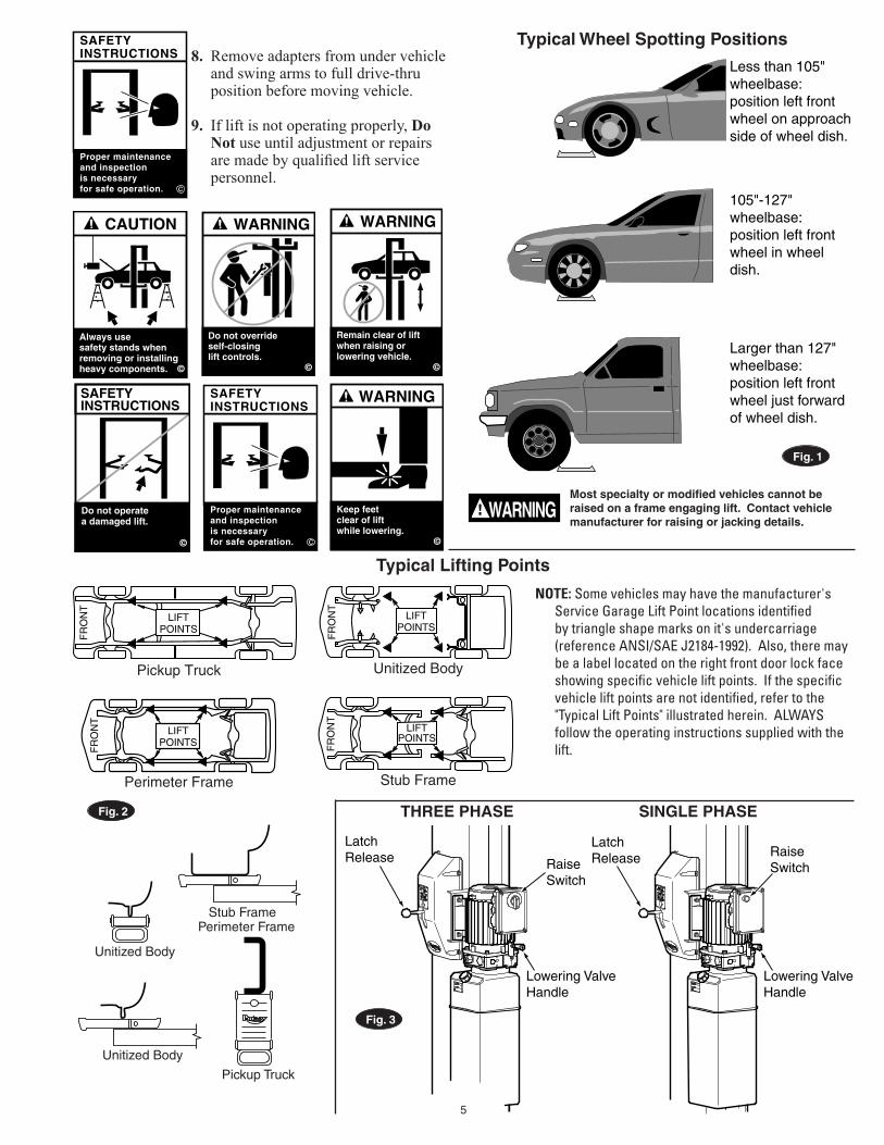
Typical Wheel Spotting Positions
CAUTION
Always use safety stands when removing or installing heavy components. ©
WARNING
Do not overrideself-closinglift controls.
©
Keep feet clear of lift while lowering.
©
WARNING
WARNING
Remain clear of liftwhen raising orlowering vehicle.
©
SAFETYINSTRUCTIONS
Do not operate a damaged lift.
©
SAFETYINSTRUCTIONS
Proper maintenanceand inspectionis necessaryfor safe operation. c
SAFETYINSTRUCTIONS
Proper maintenanceand inspectionis necessaryfor safe operation. c
Less than 105" wheelbase: position left front wheel on approach side of wheel dish.
105"-127" wheelbase: position left front wheel in wheel dish.
Larger than 127" wheelbase: position left front wheel just forward of wheel dish.
NOTE: Some vehicles may have the manufacturer's Service Garage Lift Point locations identified by triangle shape marks on it's undercarriage (reference ANSI/SAE J2184-1992). Also, there may be a label located on the right front door lock face showing specific vehicle lift points. If the specific vehicle lift points are not identified, refer to the "Typical Lift Points" illustrated herein. ALWAYS follow the operating instructions supplied with the lift.
FR
ON
T
LIFTPOINTS
FR
ON
T
LIFTPOINTS
FR
ON
T
LIFTPOINTS
FR
ON
T
LIFTPOINTS
Pickup Truck
Perimeter Frame
Unitized Body
Stub Frame
Typical Lifting Points
Most specialty or modified vehicles cannot be raised on a frame engaging lift. Contact vehicle manufacturer for raising or jacking details.
WARNING
Fig. 1
Fig. 2
Stub Frame
Pickup Truck
Perimeter Frame
Unitized Body
Unitized Body
Fig. 3
8. Remove adapters from under vehicle and swing arms to full drive-thru position before moving vehicle.
9. If lift is not operating properly, DoNot use until adjustment or repairs are made by qualified lift service personnel.
THREE PHASE SINGLE PHASE

6
CAUTION DONOT go under vehicle if locking latches are not engaged.
5.WhileUsingLift: A. Avoid excessive rocking of vehicle while on lift. B. Always use safety stands as needed or when
removing or installing heavy components.6.ToLowerLift: A. Remove all tools or other objects from lift area. B. Raise lift off locking latches. C. Pull LATCH release handle fully and hold. D. Push LOWERING valve handle to lower, Fig. 4.
Note: Both LATCH release and LOWERING valve handles are deadman-type design. Each must be held down to lower lift. Do not override self-closing lift controls.
7. Remain clear of lift when lowering vehicle. Observe pinch point warning decals.
8. Remove adapters from under vehicle. Be sure lift is fully lowered before removing vehicle.
9. If lift is not operating properly, DoNot use until adjustment or repairs are made by qualified lift service personnel.
SPOA82 OPERATING INSTRUCTIONSTo avoid personal injury and/or property damage, permit only trained personnel to operate lift. After reviewing these instructions, get familiar with lift controls by running the lift through a few cycles before loading vehicle on lift.
Always lift the vehicle using all four adapters. NEVER raise just one end, one corner, or one side of vehicle.
Authorized personnel only in lift area.
©
CAUTION
Read operatingand safety manualsbefore using lift.
©
SAFETYINSTRUCTIONS
CAUTION
Lift to be used by trained operatoronly.
©
? ??
CAUTION
Use height extenderswhen necessary to ensure good contact. ©
CAUTION
Use vehiclemanufacturer’slift points.
©
CAUTION
Auxiliary adaptersmay reduce load capacity.
©
WARNING
Remain clear of liftwhen raising orlowering vehicle.
©
CAUTION
Always use safety stands when removing or installing heavy components. ©
WARNING
Do not overrideself-closinglift controls.
©
WARNING
Remain clear of liftwhen raising orlowering vehicle.
©
ObserveandheedSAFETY,CAUTIONandWARNINGlabelsonthelift.
1. Lift must be fully lowered and service bay clear of all personnel before the vehicle is brought on lift. Swing arms out to full drive-thru position.2. Spot vehicle over lift with left front wheel in proper spotting dish position, Fig. 5. Be sure vehicle wheels and/or mud flaps clear pad end ramps.3. Loading: DO NOT raise limousines or pickup trucks. DO NOT raise SUV's, vans, or other specialty vehicles not of a unibody construction.
Beforeliftingvehiclebesurethat:A. Pads are in secure contact with frame or support structure at outer body.B. Certain vehicles such as Camaro, Firebird, Escort, or Chrysler "K" Cars or others may require additional clearance under carriage or exhaust
system from contacting pad support. Use 3" high auxiliary rubber pads. Locate under frame or support structure at outer body using vehicle manufacturer's recommended pick up points.
Note: Allow 2 seconds between motor starts. Failure to comply may cause motor burnout.
4. ToRaiseLift: A. Push RAISE switch on power unit, Fig. 4. B. Stop before making contact with vehicle. Be sure
wheels and/or mud flaps clear pad end ramps. C. Raise vehicle until tires clear the floor. D. Stop and check pads for secure contact at vehicle
manufacturer’s recommended lift points. E. Continue to raise to desired height only if vehicle is
secure on lift. F. Repeat complete spotting, loading and raising
procedures if required. H. Lower lift onto locking latches.
IMPORTANT
WARNING
WARNING
Clear area if vehicle is in danger of falling.
©

7
B M W
B M W B M W
B M W
Vehicle Spotting Position
Vehicle Loading Position
FR
ON
T
LIFTPOINTS
FR
ON
T
LIFTPOINTS
FR
ON
T
LIFTPOINTS
FR
ON
T
LIFTPOINTS
Pickup Truck
Perimeter Frame
Unitized Body
Stub Frame
Keep feet clear of lift while lowering.
©
WARNINGSAFETYINSTRUCTIONS
Do not operate a damaged lift.
©
SAFETYINSTRUCTIONS
Proper maintenanceand inspectionis necessaryfor safe operation. c
SAFETYINSTRUCTIONS
Proper maintenanceand inspectionis necessaryfor safe operation. c
Less than 105" wheelbase: position left front wheel on approach side of wheel dish.
105"-127" wheelbase: position left front wheel in wheel dish.
Larger than 127" wheelbase: position left front wheel just forward of wheel dish.
NOTE: Some vehicles may have the manufacturer's Service Garage Lift Point locations identified by triangle shape marks on it's undercarriage. Also, there may be a label located on the right front door lock face showing specific vehicle lift points. If the specific vehicle lift points are not identified, refer to the "Typical Lift Points" illustrated herein. ALWAYS follow the operating instructions supplied with the lift.
NOTE: This style lift is not recommended for pickup trucks or vehicles with truck frames.
Typical Lifting Points
Fig. 5
CAUTIONFig. 6
Latch Release Raise
Switch
Lowering ValveHandle
Latch Release
RaiseSwitch
Lowering ValveHandle
Fig. 4

8
TLO7 OPERATING INSTRUCTIONS
To avoid personal injury and/or property damage, permit only trained personnel to operate lift. After reviewing these instructions, get familiarwith lift controls by running the lift through a few cycles before loading vehicle on lift.
NEVER raise just one end, one corner, or one side of vehicle.IMPORTANT
CAUTION
WARNING
CAUTION
Lift to be used by trained operatoronly.
©
? ??
Read operatingand safety manualsbefore using lift.
©
SAFETYINSTRUCTIONS
Authorized personnel only in lift area.
©
CAUTION WARNING
Clear area if vehicle is in danger of falling.
©
CAUTION
Use vehiclemanufacturer’slift points.
©
WARNING
Remain clear of liftwhen raising orlowering vehicle.
©
CAUTION
Use height extenderswhen necessary to ensure good contact. ©
CAUTION
Auxiliary adaptersmay reduce load capacity.
©
SAFETYINSTRUCTIONS
Proper maintenanceand inspectionis necessaryfor safe operation. c
Observe and heed SAFETY, CAUTION and WARNING labels on the lift.
1. Before Loading: • Liftmustbefullyloweredandservicebayclearofallpersonnelbeforethevehicleisbroughtonlift. • Positionrearpanweldmentandfrontforkssothattheymatchvehiclewheelbaseandarecenteredoncolumns. • AssureForksandpanweldmentarefreefromgreaseandoil. • Retractforkstogivewidestdrivethrough.
2. Loading: • Positionvehiclewiththerearwheelscenteredontherearpanweldment.(Drivingoverforksispermittedwithwide
vehicles). • Moveforkssothefrontwheelsarefullycradled. • Usesmallwheeladapteronforkswhennecessary,seeFig.7. • For3-wheelvehicles,centersinglewheelonrearramp.
Usesmallwheeladapterkitwhenraisingvehicleswithlessthan13"wheels.Besuretoengagedowelscrew.
3. To Raise Lift: • PushRAISE switch on power unit, Fig. 8. • Raisevehicleuntiltiresclearthefloor. • Stopandcheckforstablecontactwithvehicle. • Continuetoraisetodesiredheightonly if vehicle is secure on lift. • Lowerliftontolockinglatches. • Seetypicalloading,Fig.9.
DONOTgoundervehicleiflockinglatchesarenotengaged.
CAUTION

9
Latch Release Raise
Switch
Lowering ValveHandle
Latch Release Raise
Switch
Lowering ValveHandle
Do not operatea damaged lift.
SAFETYINSTRUCTIONS
Proper maintenanceand inspectionis necessaryfor safe operation. c
CAUTION
Always use safety stands when removing or installing heavy components. ©
WARNING
Do not overrideself-closinglift controls.
©
WARNING
Remain clear of liftwhen raising orlowering vehicle.
©
Keep feet clear of lift while lowering.
©
WARNINGSAFETYINSTRUCTIONS
Do not operate a damaged lift.
©
4. While Using Lift: • Avoidexcessiverockingofvehiclewhileonlift. • Alwaysusesafetystandsasneededorwhenremovingorinstallingheavycomponents.
5. To Lower Lift: • Removealltoolsorotherobjectsfromliftarea. • Remainclearofliftwhenloweringvehicle.Observepinchpointwarningdecals. • Raiseliftofflockinglatches. • PushLATCH release handle fully and hold. • PullLOWERING valve handle to lower, Fig. 8.
Note: BothLATCH release and LOWERINGvalvehandlesaredeadman-typedesign.Eachmustbehelddowntolowerlift.Donot override self-closing lift controls.
If lift is not operating properly, Do Notuseuntiladjustmentorrepairsaremadebyqualifiedliftservice personnel.WARNING
Lift Controls
Use small wheel adapter kit when raising vehicles with less than 13” wheels. Be sure to engage dowel screw.CAUTION
Fig. 9
Fig. 8
Fig. 7
10
CAUTION
Lift to be used by trained operatoronly.
©
? ??
CAUTION
Always use safety stands when removing or installing heavy components. ©
The messages and pictographs shown are generic in nature and are meantto generally represent hazards common to all automotive lifts regardless ofspecific style.
Funding for the development and validation of these labels was provided bythe Automotive Lift Institute, PO Box 33116 Indialantic, FL. 32903-3116.
They are protected by copyright. Set of labels may be obtained from ALI orits member companies.
ALI/WL101cÓ 1992 by ALI, Inc.
Authorized personnel only in lift area.
©
CAUTION
CAUTION
Use vehiclemanufacturer’slift points.
©
CAUTION
Use height extenderswhen necessary to ensure good contact. ©
CAUTION
Auxiliary adaptersmay reduce load capacity.
©
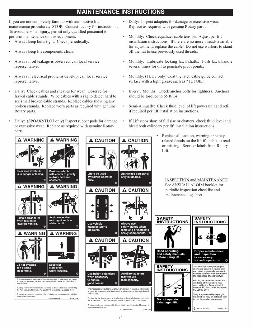
If you are not completely familiar with automotive lift maintenance procedures; STOP: Contact factory for instructions. To avoid personal injury, permit only qualified personnel to perform maintenance on this equipment.• Always keep bolts tight. Check periodically.
• Always keep lift components clean.
• Always if oil leakage is observed, call local service representative.
• Always if electrical problems develop, call local service representative.
• Daily: Check cables and sheaves for wear. Observe for frayed cable strands. Wipe cables with a rag to detect hard to see small broken cable strands. Replace cables showing any broken strands. Replace worn parts as required with genuine Rotary parts.
• Daily: (SPOA82/TLO7 only) Inspect rubber pads for damage or excessive wear. Replace as required with genuine Rotary parts.
• Daily: Inspect adapters for damage or excessive wear. Replace as required with genuine Rotary parts.
• Monthly: Check equalizer cable tension. Adjust per lift installation instructions. If there are no more threads available for adjustment, replace the cable. Do not use washers to stand off the nut to use previously used threads.
• Monthly: Lubricate locking latch shafts. Push latch handle several times for oil to penetrate pivot points.
• Monthly: (TLO7 only) Coat the latch cable guide contact surface with a light grease such as "TUFOIL".
• Every 3 Months: Check anchor bolts for tightness. Anchors should be torqued to 65 ft/lbs.
• Semi-Annually: Check fluid level of lift power unit and refill if required per lift installation instructions.
• If Lift stops short of full rise or chatters, check fluid level and bleed both cylinders per lift installation instructions.
INSPECTION and MAINTENANCE See ANSI/ALI ALOIM booklet for
periodic inspection checklist and maintenance log sheet.
SAFETYINSTRUCTIONS
Do not operate a damaged lift.
©
Read operatingand safety manualsbefore using lift.
©
SAFETYINSTRUCTIONS
The messages and pictographsshown are generic in nature andare meant to generally representhazards common to all automotivelifts regardless of specific style.
Funding for the development andvalidation of these labels wasprovided by the Automotive LiftInstitute, PO Box 33116 Indialantic,FL. 32903-3116.
They are protected by copyright.Set of labels may be obtained fromALI or its member companies.
C 1992 by ALI, Inc. ALI/WL101s
SAFETYINSTRUCTIONS
Proper maintenanceand inspectionis necessaryfor safe operation. c
WARNING
Clear area if vehicle is in danger of falling.
©
The messages and pictographs shown are generic in nature and are meantto generally represent hazards common to all automotive lifts regardless ofspecific style.
Funding for the development and validation of these labels was provided bythe Automotive Lift Institute, PO Box 33116 Indialantic, FL. 32903-3116.
They are protected by copyright. Set of labels may be obtained from ALI orits member companies.
ALI/WL101wÓ 1992 by ALI, Inc.
WARNING
Position vehicle with center of gravity midway between adapters. ©
WARNING
Remain clear of liftwhen raising orlowering vehicle.
©
Keep feet clear of lift while lowering.
©
WARNINGWARNING
Do not overrideself-closinglift controls.
©
WARNING
Avoid excessiverocking of vehiclewhile on lift.
c
MAINTENANCE INSTRUCTIONS
• Replace all caution, warning or safety related decals on the lift if unable to read or missing. Reorder labels from Rotary Lift.

11
TroubleMotor does not run.
Motor runs but will not raise lift.
Motor runs—raises unloaded lift but will not raise vehicle.
Lift slowly settles down.
Slow lifting speed or oil blowing out filler breather cap.
Lift going up unlevel.
Anchors will not stay tight.
Locking latches do not engage.
Locking latches do not disengage.
Lift stops short of full rise or chatters.
Remedy1. Replace blown fuse or reset circuit
breaker.2. Supply correct voltage to motor.3. Repair and insulate all connections.4. Replace switch.5. Replace switch.6. Replace motor.
1. Repair or replace lowering valve.2. Tighten all suction line fittings.3. Replace suction stub.4. Fill tank to proper level with ISOVG32
Hydraulic Oil or Dexron III ATF.
1. Supply correct voltage to motor.2. Clean lowering valve.3. Replace relief valve cartridge.4. Check vehicle weight and/or balance
vehicle weight on lift.
1. Clean check valve.2. Clean lowering valve.3. Repair external leaks.
1. Change oil using ISOVG32 Hydraulic Oil or Dexron III ATF.
2. Tighten all suction line fittings.3. Reinstall oil return tube.
1. Adjust equalizer cables to correct tension.
2. Shim lift to level columns (Not to exceed 1/2”). If over 1/2” break out floor and repour per lift installation instructions.
1. Relocate lift using a new bit to drill holes. Reference installation instructions for minimum spacing requirements.
2. Break out old concrete and repour new pads for lift per lift installation instructions.
1. Remove covers, oil latch mechanism. Actuate latch release handle several times to allow oil to coat shaft.
2. Replace broken spring.3. Adjust clamp at cable end per lift
installation instructions.
1. Replace cable.2. Check position of cable on sheaves/
upper guides; adjust cable tension.3. Adjust cable tension.
1. Fill tank to proper level with ISOVG32 Hydraulic Oil or Dexron III ATF.
2. Bleed lift per installation instructions.
Cause1. Blown fuse or circuit breaker.
2. Incorrect voltage to motor.3. Bad wiring connections.4. Motor up switch burned out.5. Overhead limit switch burned out.6. Motor windings burned out.
1. Open lowering valve.2. Pump sucking air.3. Suction stub off pump.4. Low oil level.
1. Motor running on low voltage.2. Debris in lowering valve.3. Improper relief valve adjustment.4. Overloading lift.
1. Debris in check valve seat.2. Debris in lowering valve seat.3. External oil leaks.
1. Air mixed with oil.
2. Air mixed with oil suction.3. Oil return tube loose.
1. Equalizer cables out of adjustment.
2. Lift installed on unlevel floor.
1. Holes drilled oversize.
2. Concrete floor thickness or holding strength not sufficient.
1. Latch shafts rusted. (Usually occurs on outside installations or in high humidity areas such as vehicle wash bays.)
2. Latch spring broken.3. Latch cable needs adjustment.
1. Latch cable is broken.2. Cable is off sheaves/upper guides.
3. Latch cable is loose.
1. Low oil level.
2. Air in hydraulic lines/cylinder.
TROUBLE SHOOTING

12
Purpose
This procedure establishes the minimum requirements for the lockout of energy that could cause injury to personnel by the operation of lifts in need of repair or being serviced. All employees shall comply with this procedure.
Responsibility
The responsibility for assuring that this procedure is followed is binding upon all employees and service personnel from outside service companies (i.e., Authorized Rotary Installers, contactors, etc.). All employees shall be instructed in the safety significance of the lockout procedure by the facility owner/manager. Each new or transferred employee along with visiting outside service personnel shall be instructed by the owner/manager (or assigned designee) in the purpose and use of the lockout procedure.
Preparation
Employees authorized to perform lockout shall ensure that the appropriate energy isolating device (i.e., circuit breaker, fuse, disconnect, etc.) is identified for the lift being locked out. Other such devices for other equipment may be located in close proximity of the appropriate energy isolating device. If the identity of the device is in question, see the shop supervisor for resolution. Assure that proper authorization is received prior to performing the lockout procedure.
SequenceofLockoutProcedure
1) Notify all affected employees that a lockout is being performed and the reason for it.2) Unload the subject lift. Shut it down and assure the disconnect switch is “OFF” if one is provided
on the lift.3) The authorized lockout person operates the main energy isolation device removing power to the
subject lift.• If this is a lockable device, the authorized lockout person places the assigned padlock on
the device to prevent its unintentional reactivation. An appropriate tag is applied stating the person’s name, at least 3” x 6” in size, an easily noticeably color, and states not to operate device or remove tag.
• If this device is a non-lockable circuit breaker or fuse, replace with a “dummy” device and tag it appropriately as mentioned above.
4) Attempt to operate lift to assure the lockout is working. Be sure to return any switches to the “OFF” position.
5) The equipment is now locked out and ready for the required maintenance or service.
RestoringEquipmenttoService
1) Assure the work on the lift is complete and the area is clear of tools, vehicles, and personnel.2) At this point, the authorized person can remove the lock (or dummy circuit breaker or fuse) &
tag and activate the energy isolating device so that the lift may again be placed into operation.
RulesforUsingLockoutProcedure
Use the Lockout Procedure whenever the lift is being repaired or serviced, waiting for repair when current operation could cause possible injury to personnel, or for any other situation when unintentional operation could injure personnel. No attempt shall be made to operate the lift when the energy isolating device is locked out.
LIFT LOCKOUT/TAGOUT PROCEDURE
13
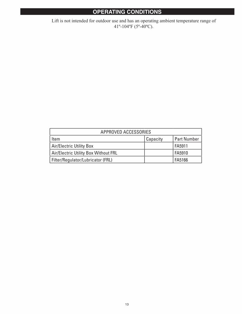
APPROVEDACCESSORIESItem Capacity Part NumberAir/ElectricUtilityBox FA5911Air/ElectricUtilityBoxWithoutFRL FA5910Filter/Regulator/Lubricator (FRL) FA5166
OPERATING CONDITIONS
Lift is not intended for outdoor use and has an operating ambient temperature range of 41º-104ºF (5º-40ºC).

14
NOTES

15
NOTES

TrainedOperatorsandRegularMaintenanceEnsuresSatisfactoryPerformanceofYourRotaryLift.
ReplacementParts: See installers package for parts breakdown sheet. Order Genuine Rotary replacement parts from your nearest Authorized Parts Distributor.
MaintenanceAssistance: Contact your local Rotary distributor.
Should further assistance be required, contact Rotary Lift, at one of the phone numbers listed below.
© Rotary®, Printed in U.S.A., All RightsReserved. Unless otherwise indicated, ROTARY, DOVER and all other trademarks are property of Dover Corporation and its affiliates.
Rotary World Headquarters2700 Lanier DriveMadison, IN 47250, USAwww.rotarylift.com
North America Contact Information Tech. Support: p 800.445.5438 f 800.578.5438 e [email protected] Sales: p 800.640.5438 f 800.578.5438 e [email protected]
World Wide Contact InformationWorld Headquarters/USA: 1.812.273.1622Canada: 1.905.812.9920European Headquarters/Germany: +49.771.9233.0United Kingdom: +44.178.747.7711Australasia: +60.3.7660.0285Latin America / Caribbean: +54.3488.431.608Middle East / Northern Africa: +49.771.9233.0