Embed Size (px)
Citation preview
OOF Project Update
Rhonald Lua, Andrew Reid,Stephen Langer, Valerie Coffman
Outline
I. Automatic Skeleton constructionII. One-dimensional interfacesIII. 3D Viewer mock-upIV. Plasticity overview
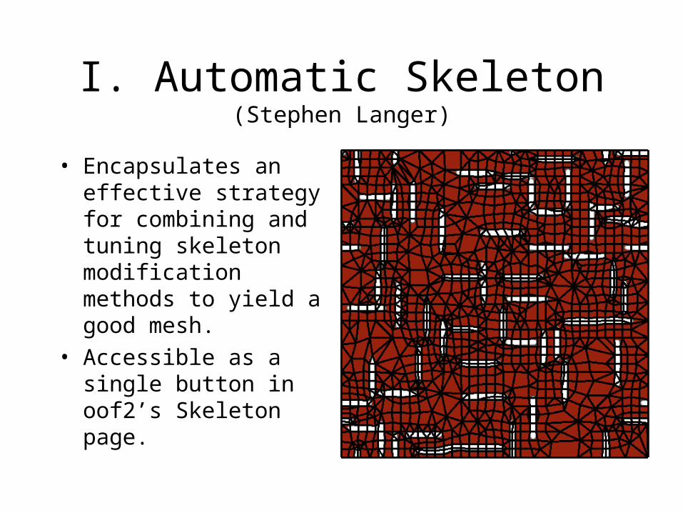
I. Automatic Skeleton(Stephen Langer)
• Encapsulates an effective strategy for combining and tuning skeleton modification methods to yield a good mesh.
• Accessible as a single button in oof2’s Skeleton page.
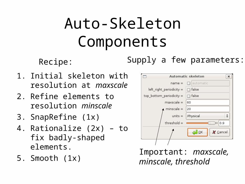
Auto-Skeleton Components
1. Initial skeleton with resolution at maxscale
2. Refine elements to resolution minscale
3. SnapRefine (1x)4. Rationalize (2x) – to fix
badly-shaped elements.
5. Smooth (1x)
Supply a few parameters:
Important: maxscale,minscale, threshold
Recipe:
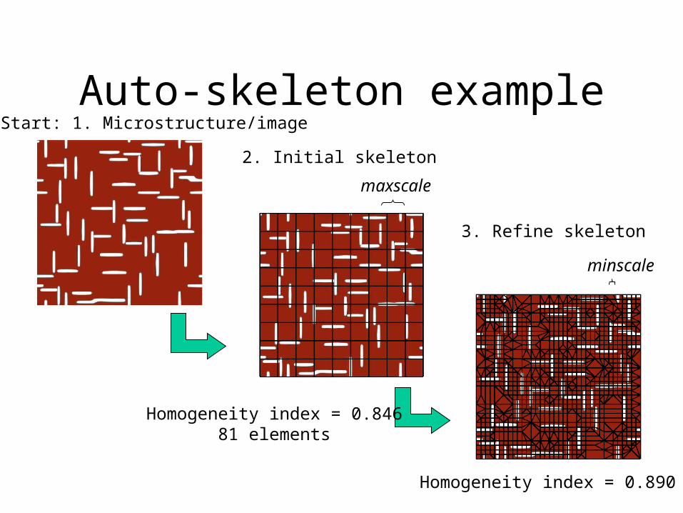
Auto-skeleton exampleStart: 1. Microstructure/image
2. Initial skeleton
maxscale
minscale
3. Refine skeleton
Homogeneity index = 0.84681 elements
Homogeneity index = 0.890

…example continued4. SnapRefine skeleton(place new edges and nodes at material boundaries)
Homogeneity index = 0.890 Homogeneity index = 0.981
3.

…example continued
Homogeneity index = 0.981
Homogeneity index = 0.981
Homogeneity index = 0.982
5. Rationalize skeleton(fix badly-shaped elements)
Finish: 6. Smooth skeleton(move a node to the average position of its neighbors. Improves element quality and/or shape.)
4.
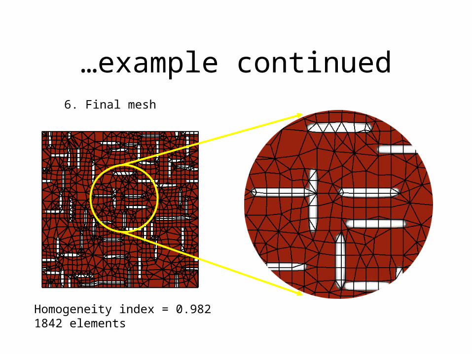
…example continued6. Final mesh
Homogeneity index = 0.9821842 elements
II. One-dimensional Interfaces: goals
• Define one dimensional interfaces and create associated 1-D elements within 2-D mesh.
• Incorporate physics of surface (line) tension, heat source/line charge. Define cracks (insulation) and jumps or discontinuities in field values across an interface.
• Attach materials and properties to 1-D elements. Specify constitutive rules.
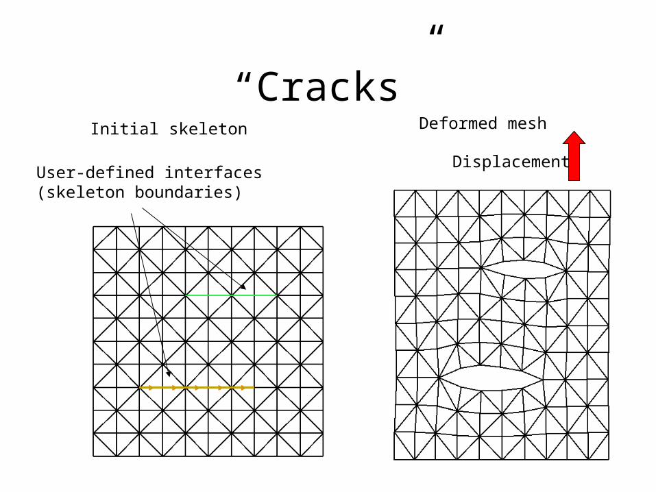
“Cracks”Initial skeleton Deformed mesh
User-defined interfaces(skeleton boundaries)
Displacement

…continuedStress (trace) field
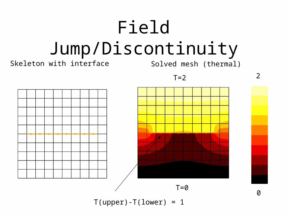
Field Jump/DiscontinuitySolved mesh (thermal)
0
T=2
T=0
Skeleton with interface
2
T(upper)-T(lower) = 1
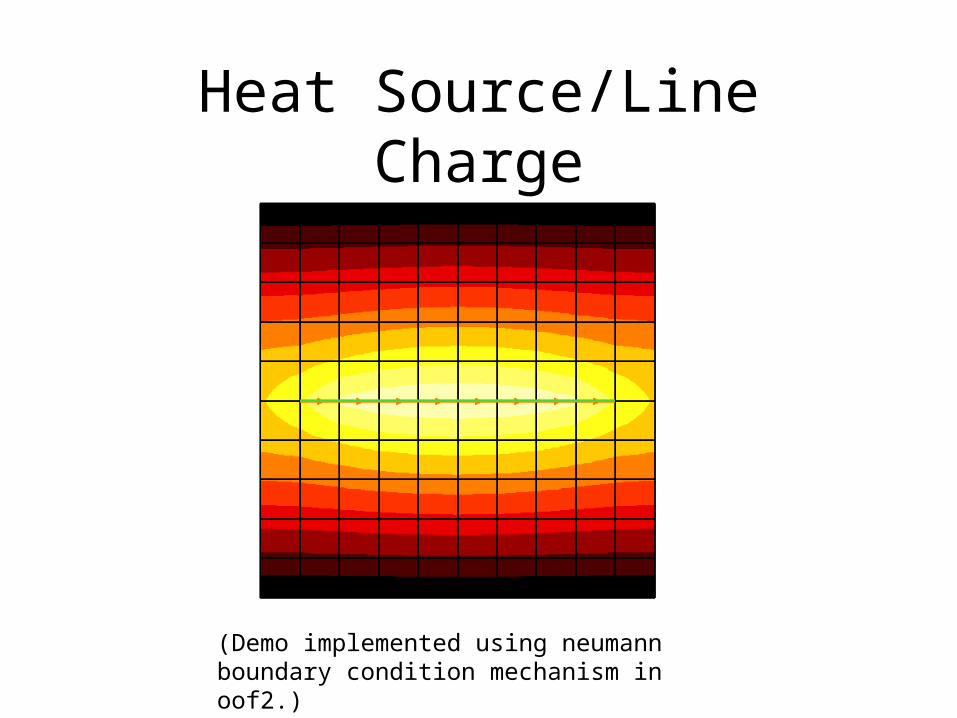
Heat Source/Line Charge
(Demo implemented using neumann boundary condition mechanism in oof2.)
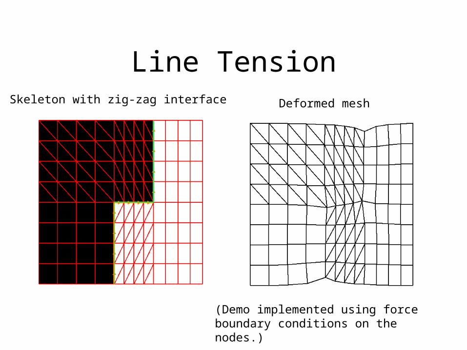
Line TensionSkeleton with zig-zag interface Deformed mesh
(Demo implemented using force boundary conditions on the nodes.)
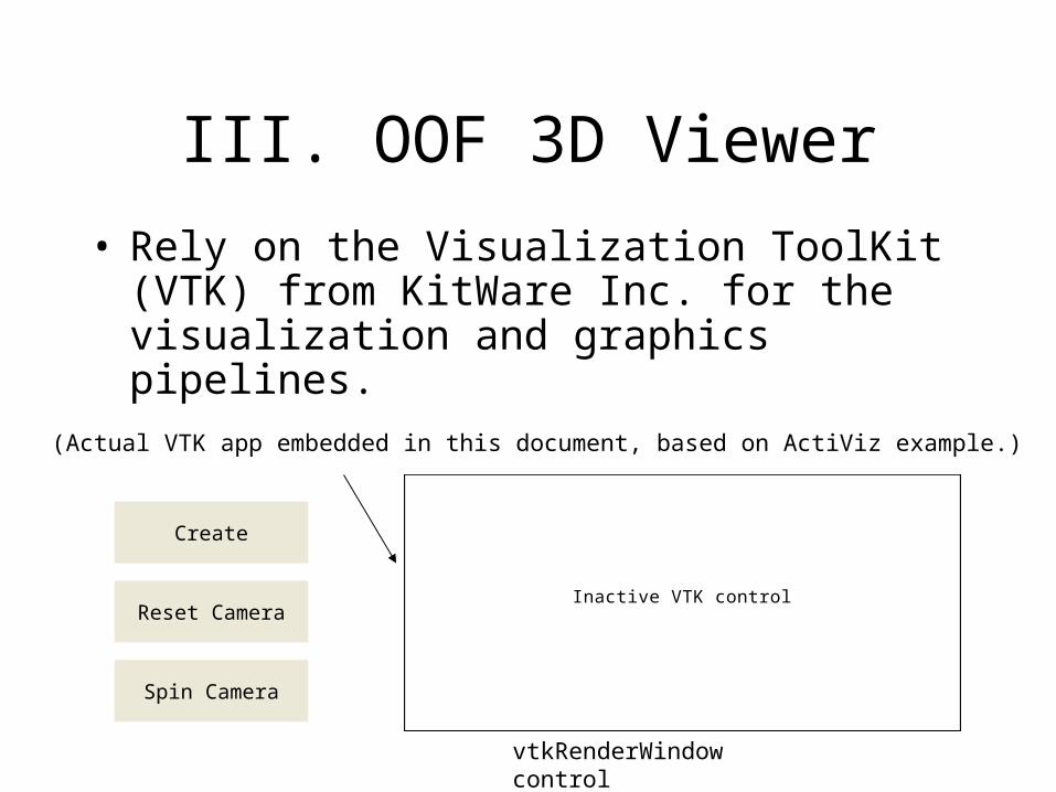
III. OOF 3D Viewer
Inactive VTK control
Create
Reset Camera
Spin Camera
(Actual VTK app embedded in this document, based on ActiViz example.)
• Rely on the Visualization ToolKit (VTK) from KitWare Inc. for the visualization and graphics pipelines.
vtkRenderWindow control
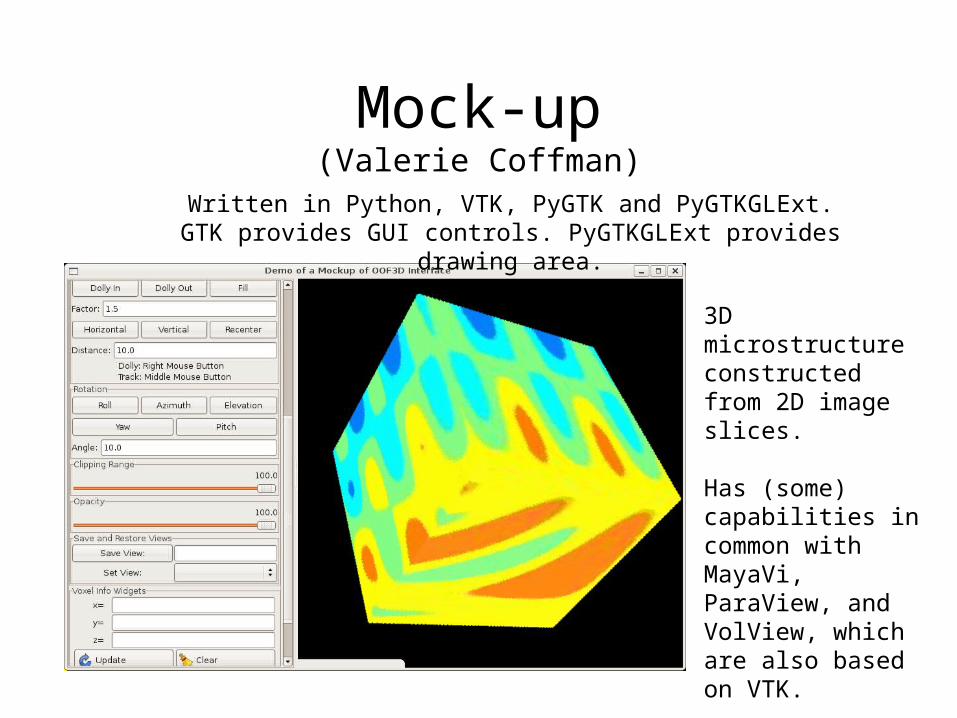
Mock-up(Valerie Coffman)
Written in Python, VTK, PyGTK and PyGTKGLExt.GTK provides GUI controls. PyGTKGLExt provides drawing
area.
3D microstructure constructed from 2D image slices.
Has (some) capabilities in common with MayaVi, ParaView, and VolView, which are also based on VTK.

Features of the Viewer
• View object from different perspectives (tumble, pan, zoom, etc.)
• View sections of the object (clipping, cross sections on arbitrary planes, etc.)
• Vary transparency or opacity (depth-dependent, etc.)
• Pick or select voxels.
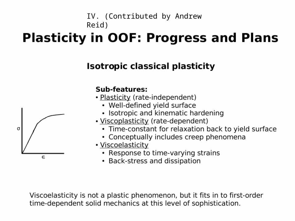
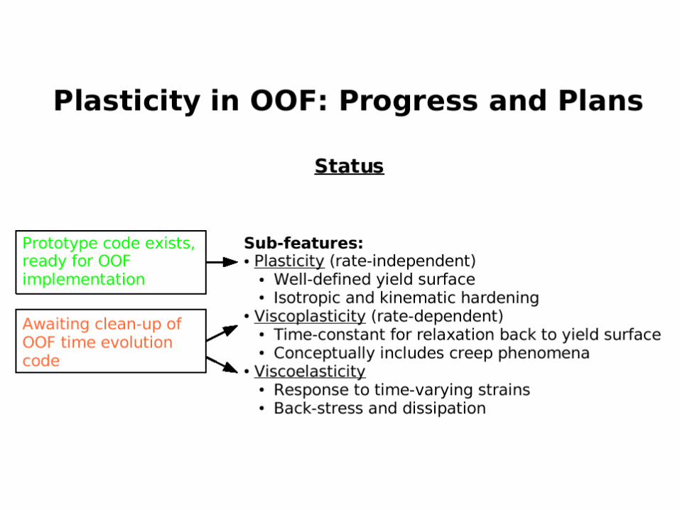
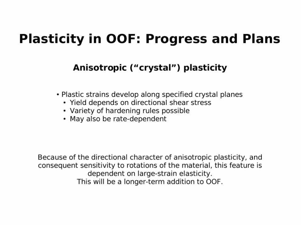
IV. (Contributed by Andrew Reid)

The end. Thank you.