Embed Size (px)
Citation preview

Objektum orientált szoftverek tesztelése
2
OO sajátosságok! adat-elrejtés! egymásra ható független objektumok
saját állapotokkal (nincs egy megosztott globális állapot )
! a rendszer struktúrája helyett a viselkedésén van a hangsúly
! kód újrafelhasználás! egységbezárás! öröklés! többalakúság

3
OO következmények! Egységbezárás
! az osztályok nem funkcionális részprogramok (metódusok)
! nehéz integrációs tesztelés (állapot beállítás)
! Adat elrejtés! állapot vizsgálat az objektum interfészén
keresztül
! Örökl!dés! többszörös tesztelés szükségessége
4
OO következmények (folyt.)! Tesztelési szintek
! Mi egy egység?
! Kompozíciós stratégia! Integrációs és rendszer tesztelés
! GUI! UML-alapú tesztelés

5
Teszttervezés! Várható hibák alapján
! OO meggondolások! Bizonyos hibák kisebb valószín"séggel! Bizonyos hibák nagyobb valószín"séggel! Újfajta hibák
! Várható felhasználás alapján! Scenárió alapú tesztelés
6
Újfajta hibák! Örökl!dés, többalakúság
! milyen kód hajtódik végre metódus híváskor?
! jó-e a paraméterek formája?! pl.: base::foo() derived::foo()! teszt nyílvántartás (kontextus) változása

7
Hibavalószín"ség változása! OO metódusok általában rövidebbek
! inkább integrálási problémák
8
A rendszer szétbontása! objektumok, osztályok -> modul
tesztelés! együttm!köd" osztályok -> osztály
csoport tesztelés (integrációs teszt)
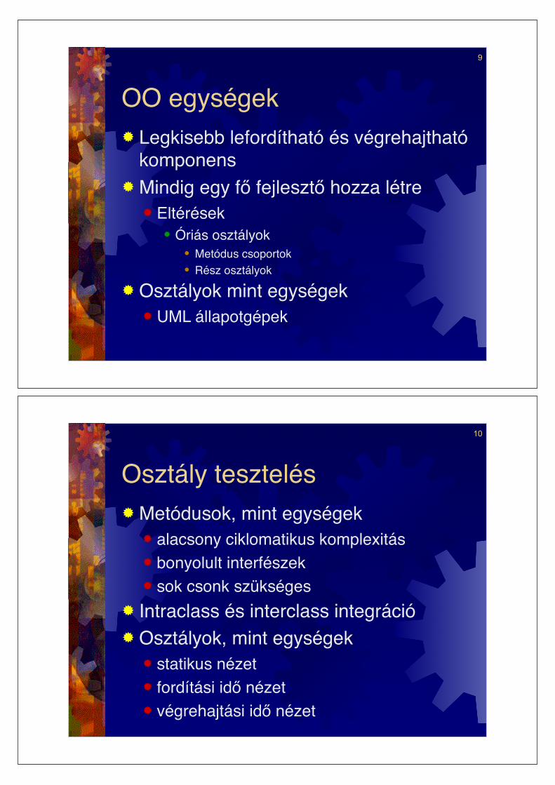
9
OO egységek! Legkisebb lefordítható és végrehajtható
komponens! Mindig egy f! fejleszt! hozza létre
! Eltérések! Óriás osztályok
" Metódus csoportok" Rész osztályok
! Osztályok mint egységek! UML állapotgépek
10
Osztály tesztelés! Metódusok, mint egységek
! alacsony ciklomatikus komplexitás! bonyolult interfészek! sok csonk szükséges
! Intraclass és interclass integráció! Osztályok, mint egységek
! statikus nézet! fordítási id! nézet! végrehajtási id! nézet
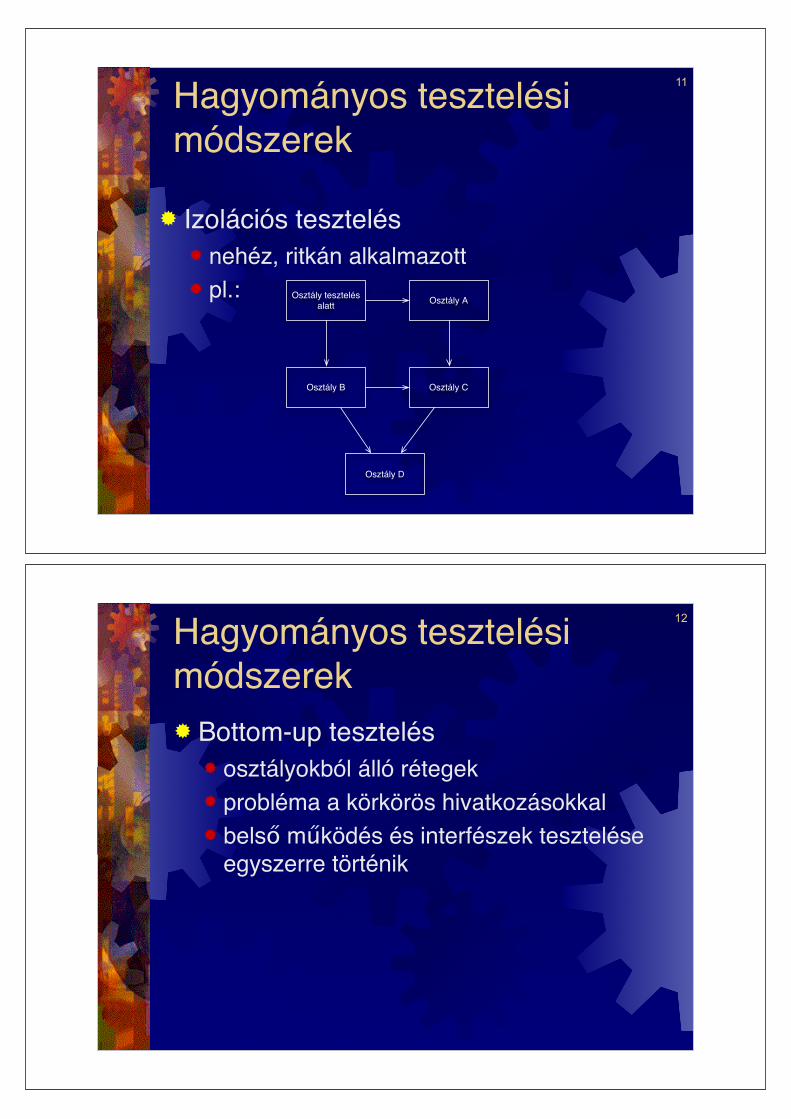
11
Hagyományos tesztelési módszerek
! Izolációs tesztelés ! nehéz, ritkán alkalmazott! pl.: Osztály tesztelés
alattOsztály A
Osztály D
Osztály COsztály B
12
Hagyományos tesztelési módszerek! Bottom-up tesztelés
! osztályokból álló rétegek! probléma a körkörös hivatkozásokkal! bels" m!ködés és interfészek tesztelése
egyszerre történik
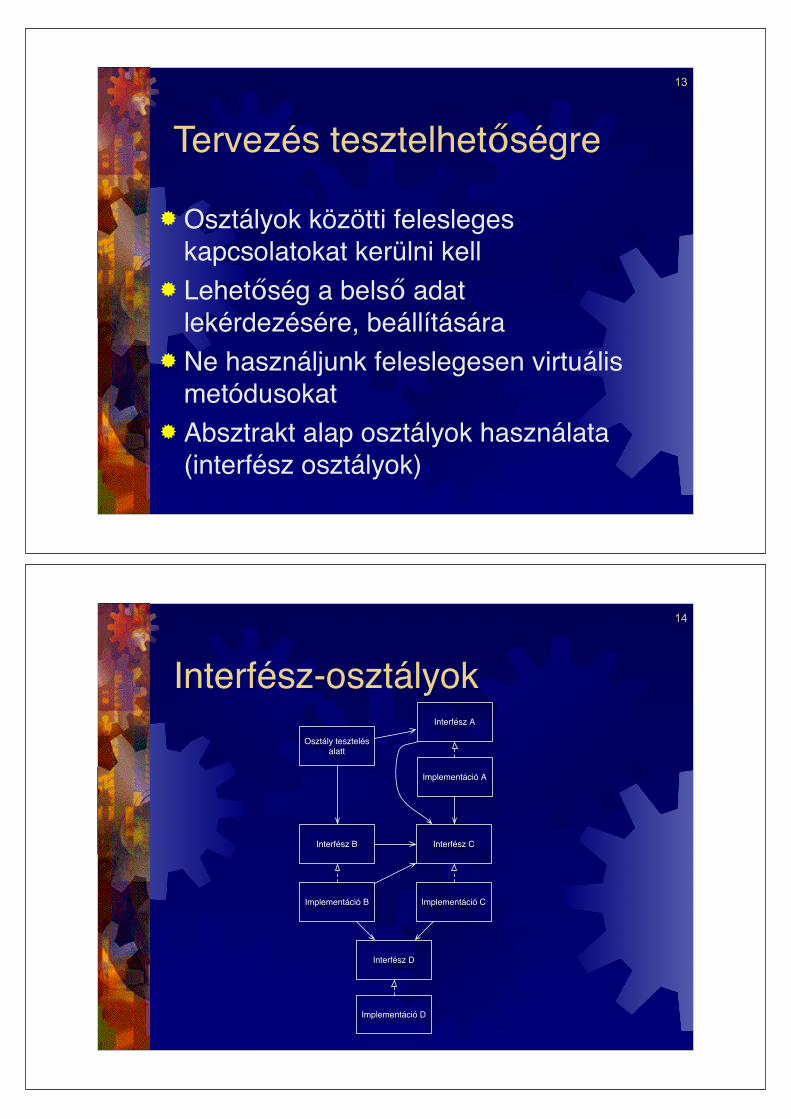
13
Tervezés tesztelhet"ségre
! Osztályok közötti felesleges kapcsolatokat kerülni kell
! Lehet"ség a bels" adat lekérdezésére, beállítására
! Ne használjunk feleslegesen virtuális metódusokat
! Absztrakt alap osztályok használata (interfész osztályok)
14
Interfész-osztályok
Osztály tesztelés alatt
Interfész A
Interfész D
Interfész CInterfész B
Implementáció A
Implementáció CImplementáció B
Implementáció D

15
OO tesztek végrehajtása! Tesztmeghajtó, f!program! Tesztel! keretrendszer és
tesztosztályok csatlakoztatása
16
JUnit egység-tesztel! keret! Java programok egység-tesztelése! Automatikus tesztelés
! Tesztkészletek végrehajtása! Fejlesztéssel egyidej" teszteset tervezés
! Tesztfutások “értékelése”! eredmények értékelése
! Teszteredmények rögzítése
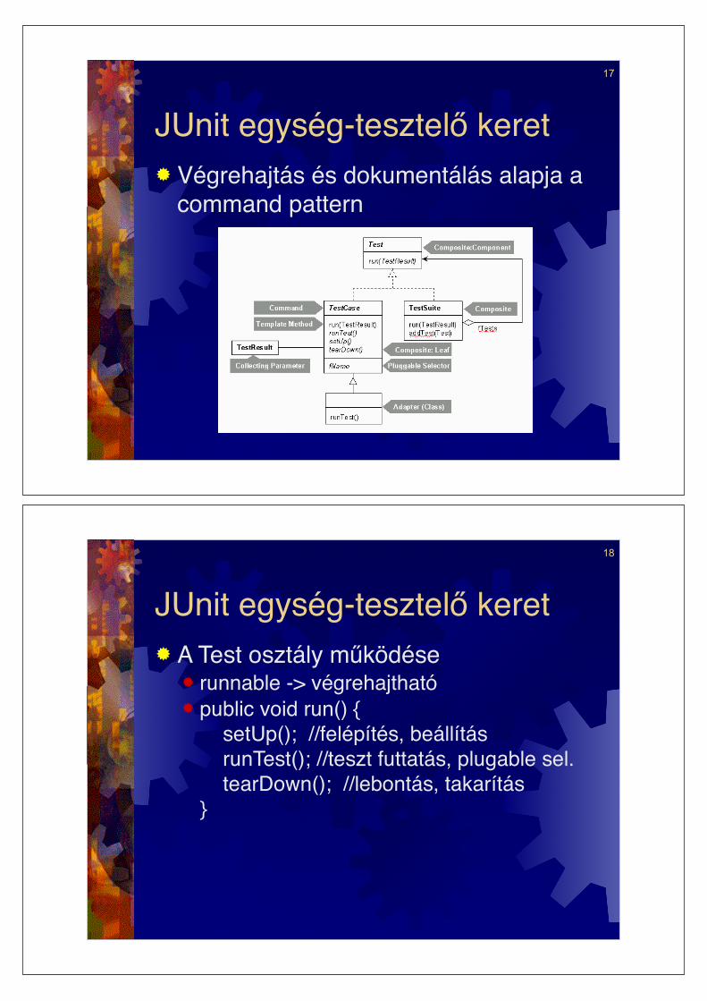
17
JUnit egység-tesztel! keret! Végrehajtás és dokumentálás alapja a
command pattern
18
JUnit egység-tesztel! keret! A Test osztály m"ködése
! runnable -> végrehajtható! public void run() {
setUp(); //felépítés, beállítás runTest(); //teszt futtatás, plugable sel. tearDown(); //lebontás, takarítás}

19
JUnit egység-tesztel! keret! Teszt metódusok
! tesztelend! kód hívása! kijelentések a helyes eredményekre
vonatkozóan! assert(’2’==ch)! assertEquals(’2’,ch)! fail()
! TestSuite-ok létrehozása! ekvivalencia osztályok! határérték analízis! stb.
20
JUnit egység-tesztel! keret! Hiba kezelés
! failure (erre számítunk, teszteredmény)! error (erre nem számítunk)! public void run(TestResult result) {
result.startTest(this); setUp(); try { runTest(); } catch (AssertionFailedError e) { //1 result.addFailure(this, e); } catch (Throwable e) { // 2 result.addError(this, e); } finally { tearDown(); } }

21
JUnit egység tesztel! keret! IDE integráció (pl. eclipse, netbeans)
! Text interface! Grafikus felület
22
Öröklési kontextus metrikák szükségessége
Bázis osztály
Lesz. B
Örökölt metódusok
Új metódusok
Lesz. A
Örökölt metódusok
Új metódusok

23
1. Példa! bázis osztály
! inherited(int x)... if(x<0) x=x/redef();...
! redef() : int 1..10
! leszármaztatott osztály! redef() : int 0..20
24
Állapot kontextus! Állapotgép alapú tesztelés
! állapot függ! viselkedés! állapot-kontextus metrikák
! Belépési pont lefedés állapot-kontextussal
25
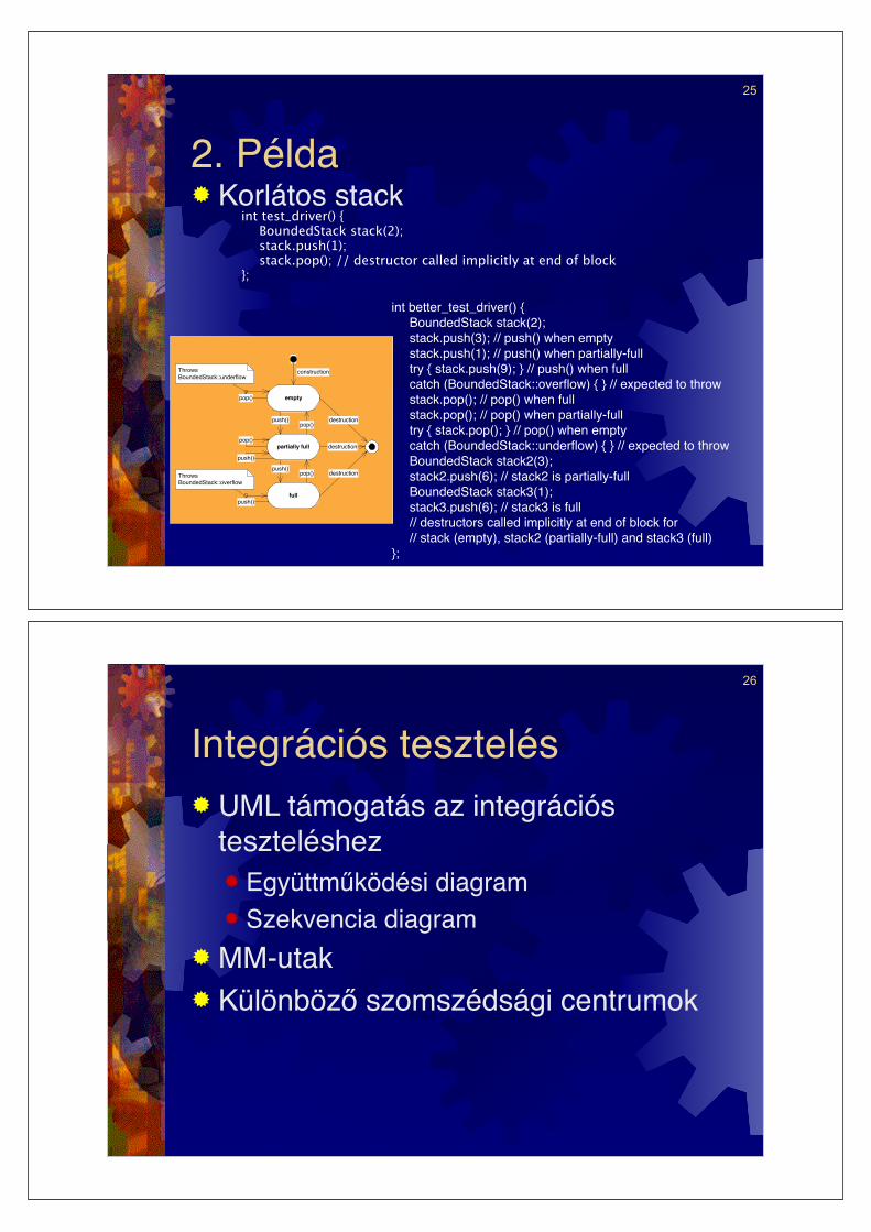
2. Példa! Korlátos stack
int test_driver() { BoundedStack stack(2); stack.push(1); stack.pop(); // destructor called implicitly at end of block
};
©IPL Information Processing Ltd
10
4.2. Using White-Box Coverage Metrics
If entry-point coverage does not ensure thorough testing, perhaps we should use a
stronger coverage requirement, say, 100% decision coverage. Unfortunately, there are
disadvantages to the adoption of such a requirement.
One factor is that there may be decisions in the code which do not correspond to
features of the public interface. Typical examples include error handling code and
defensive programming idioms. In these cases, 100% decision coverage may be
difficult to achieve.
A more significant problem is the inability of traditional structural coverage metrics to
identify code which is missing altogether. For example, consider what would happen
if the BoundedStack implementor forgot to check for the stack-empty condition in
pop(). Requiring 100% decision coverage would not help find this fault – the
missing condition is not there to be covered!
4.3. We Can Do Better
Actually, we can write a better test set than that required by any traditional structural
coverage metric, and without any knowledge of the internal details of the class.
The UML state transition diagram (see figure 6) shows how the behaviour of the class
changes, depending on the current state. This type of diagram is commonly used to
describe the state-dependent behaviour of classes
empty
partially full
full
H
construction
H
destruction
destruction
destruction
push()
push()pop()
pop()
push()
pop()
push()
pop()
Throws
BoundedStack::underflow
Throws
BoundedStack::overflow
Figure 6: State transition diagram for BoundedStack
We can use the additional information provided in the state transition diagram to
design a test set which thoroughly exercises the BoundedStack class.
4.4. Writing State-Driven Test Cases
The aim of our test design is to exercise every method in every possible state. In the
improved test set which follows, the push() and pop() methods are invoked on an
empty, partially full and full stack:
int better_test_driver() { BoundedStack stack(2); stack.push(3); // push() when empty stack.push(1); // push() when partially-full try { stack.push(9); } // push() when full catch (BoundedStack::overflow) { } // expected to throw stack.pop(); // pop() when full stack.pop(); // pop() when partially-full try { stack.pop(); } // pop() when empty catch (BoundedStack::underflow) { } // expected to throw BoundedStack stack2(3); stack2.push(6); // stack2 is partially-full BoundedStack stack3(1);stack3.push(6); // stack3 is full // destructors called implicitly at end of block for // stack (empty), stack2 (partially-full) and stack3 (full)
};
26
Integrációs tesztelés! UML támogatás az integrációs
teszteléshez! Együttm"ködési diagram! Szekvencia diagram
! MM-utak! Különböz! szomszédsági centrumok

27
Integrációs tesztelés (folyt.)! Metódus-Üzenet utak
! üzenetekkel összekötött metódus végrehajtási szekvencia
! Stimulus-Válasz utak! események kiváltotta rendszerszint"
metódus-üzenet út szekvencia
28
Kombinált osztály állapotgépek! Objektum viselkedése -> állapot
átmeneti szabályok! állapot (példány és osztály változók)! események (metódus hívások)! !rfeltételek (predikátumok a változók
felett)! tevékenységek (értékadások,
metódushívások)

29
Kombinált osztály állapotgépek (folyt.)! Komponens folyam gráf
! elemei! adat és vezérlés folyam a tesztelés
szempontjából releváns átmenetekre! forrás és cél állapot! !rfeltétel! tranzíció
! kommunikáló objektumokon keresztül! actor és mutator metódusok
" def és use helyzetek
Sss
Gt
Tt
Sts
30
Kombinált osztály állapotgépek (folyt.)! komponens folyam gráf pl.
variable v. This transition as represented in a componentflow graph is presented in Figure 2. The transition node isT1, the guard node is G1, and Sa and Sb are the source andtarget state nodes. Transition nodes that define a variableare labeled, such as def v on node T1. Uses of v are rep-resented by points ui on edges and inside transition nodes.Both Sa and Sb use v (u1 and u3) in their predicate defini-tions. Function f() is invoked from some other transition,which is represented by transition node Tx. The get func-tion for v is represented by transition node Tva if obj1 is instate Sa when it’s called, and by Tvb if obj1 is in state Sb.
T x
S b G 1 S a
T y
T va
T 1
T vb
S d G 2 S c T 2
S f G 3 S e T 3
call f ()
call h (p) call g ()
f ()
g ()
h (p)
def v
get v get v
u 1
rest
u 2 u 3
u 4 u 5
u 6 u 7
Obj1�
Obj2�
Obj3�
Figure 2: Portion of Component Flow Graph
Consider obj2, and a transition t2 (transition node T2). Theguard predicate for t2 (G2) calls the get function for v inobj1. This get is represented by two edges from obj1, bothlabeled by get v. G2 uses v (u4), and for it to evaluate totrue, the mutator function g() must be called by some otheraction (represented by Ty) when obj2 is in state Sc. Theaction of T2 uses v (u5) and sends a message to obj3 byinvoking the mutator function h(), passing the value of v asa parameter. Obj2 changes to state Sd as the target stateof transition t2.
Transition t3 handles the function call of h() when obj3 is instate Se, if the guard predicate for t3 evaluates to true. Theguard of t3 (G3) uses the value of the incoming parameter p,which has the value of v, represented by use u6. The actionof t3 uses the value in a computation (u7). After the actionof t3 is complete, obj3 changes to the target state Sf .
In the figure, edges from transition nodes to state nodesthat result from calling mutator functions in another classare labeled with the name of that function (callf(), callg(),and callh()). Function names are also put on edges fromtransition nodes to guard, state, and transition nodes if theedge is a result of a call to a get function in another class(get v). Edges from source state nodes to guard and transi-tion nodes are also labeled with the function that is called(f(), g(), and h()). These labels are used to access meta-data about the functions when the component flow graph istraversed.
In a general data flow graph, uses of a variable in a statepredicate are represented by use labels on all edges leavingthe corresponding state node (u1, u2, u3); uses of a variableor parameter in a guard predicate are represented by uselabels on all edges leaving the corresponding guard node(u4, u6). These are called predicate uses. Uses of a variablein the action of a transition are called computational uses(u5, u7). Uses of a variable in a passed parameter are calledparameter uses (u6, u7).
To summarize, Figure 2 represents the data and control flowresulting from definition of variable v by a call of functionf in obj1, the predicate and computational use of v’s valuein obj2, the passing of that value as a parameter to functionh(p), and the resulting predicate and computational param-eter use of v in the guard and action of t3 in obj3.
3. COVERAGE CRITERIA
A number of different coverage criteria can be defined ondata flow graphs, including all-defs, all-uses and all-paths.These have been discussed and compared extensively in theliterature [5, 7, 9, 10, 13]. The object-oriented testing method-ology described here follows the lead of other researchers andfocuses on defs and uses of class variables in each object.This allows a tester to focus on testing criteria that requiretraversal of a def-use path in the component flow graph froma transition node that defines a variable to a node or edgethat uses the variable, with no re-definition of the variableat any node along the path.
The all-uses testing criterion applied to a component flowgraph requires tests to execute at least one path from eachdefinition of a variable at a transition node to each reachableuse at another node or edge. In Figure 2, applying the all-uses criterion to variable v in class A requires tests that willforce execution of def-use paths from transition node T1 toeach of the uses u1 to u7. In the portion of the componentflow graph pictured, one sees that uses u1 and u2 are notreachable from T1 and that any path from T1 to u7 willinclude subpaths from T1 to each of the uses u3, u4, u5 andu6.
In general, it is desirable to find two different kinds of pathsin the component flow graph. One is a def-use path from thedefinition of a variable to a use that includes as many otheruses as possible. Another is an ext-int path from an externaltransition that can be executed by a tester, which in turnforces execution of other transitions that need to be executedas part of a def-use path. Both types of paths can be seenin Figure 2. The path T1 : Sb : Twb : G2 : T2 : Se : G3 : T3
is of the def-use type and paths Tx : Sa : G1 : T1 andTy : Sc : G2 : T2 are of ext-int type. In the def-use path,execution of transition T1 defines v and moves obj1 to therest state Sb. Then execution of transition T2 gets the valueof v from obj1 and forces traversal of the remainder of thepath. If the methods of T1 and T2 are internal functionsthat cannot be executed directly by a tester, then one mustbe able to find external functions that can be executed by atester in a sequence that forces traversal of the def-use path.
Construction of def-use paths must satisfy the following prop-erties:

31
Kombinált osztály állapotgépek (folyt.)! Lefedési kritériumok
! adatfolyam lefedési kritériumok! all-defs, all-uses, all-paths
! Teszt végrehajtás! tesztelés szempontjából két fajta út
! def-use (lehet!leg minél több use tartalmazásával)
! ext-int (küls! tranzíció)! privát metódusok közvetlenül nem
hívhatók! “nyugalmi” állapotok
32
Kombinált osztály állapotgépek (folyt.)! Teszt specifikálás def-use úthoz
G 2 S b T 1 T vb
v () T 3 S e T 2 G 3
h h
T 5
S y
S c
S 2
T y
T 4
S 3 F 1
F 5
F 2
g
g
f f
F 3
F 4
rest�
rest�
rest�
rest�
def� use�
G 1
T 6 S x
S a
S 1
T x
Figure 3: External Function Calls to Traverse a Def-Use Path
in black box testing. The goal of this research is to identifya sequence of functions Fi from F that when executed in theidentified order will cover as many paths in CTP as possible.
Given a software system consisting of multiple objects, itssystem state at a given point in time is defined to be thestate of each object at that time. Suppose a program is insome initial system state SS0 and suppose an external func-tion F1 is executed with some choice of values for any of itsinput parameters. Depending on the object states identifiedby SS0, and depending on the values chosen for any inputparameters, traversal of a subset of paths in EXT will beinitiated. Since none of the paths in EXT have any reststates, each path will be traversed to its ending transitionnode. But, by construction of such paths, this node maybe the head definition node of a number of def-use paths inCTP, each of which will be initiated and traversed up to itsfirst rest state. If a path in CTP has no rest states, then theentire def-use path will be completed and one can concludethat execution of F1 covers all such paths. At the completionof all triggered transitions identified by these paths, the soft-ware system will be in a new system state SS1. The testercould then execute a second external function F2 to initiateanother subset of ext-int paths from EXT. Some of thesepaths may then, in turn, initiate a set of new def-use pathsfrom CTP. In addition, every execution of a transition inthe middle of an ext-int path, or in the middle of a leg be-tween rest states of a def-use path, may call functions thattrigger the next transition in a previously initiated def-usepath that is currently in a rest state. Figure 4 presents thepossibilities of choosing successive functions from F to initi-ate new EXT paths, which in turn initiate new CTP pathsor force traversal along existing CTP paths to the next reststate. Rest state nodes in a def-use path are labeled r, andtransition nodes that force traversal from a rest state to anew leg in a def-use path are labeled t.
An external function Fi may initiate multiple paths in EXTand each EXT path may initiate or extend multiple pathsin CTP. Many of these paths will be mutually inconsis-tent. Some will have contradictory guard predicates, somewill violate the state compatibility rule for paths, and somewill re-define a variable that has already been defined bya definition node at the head of a def-use path. It will benecessary to analyze, very carefully, all initiated paths one
r�
t�
r�
r�
t�
r�r�
t�
F�1�
F�n�
F�2�
SS�0�
SS�n-1�
SS�1�
External�Functions�
F�
System�States�
SS�
ext-int�Paths�EXT�
def-use�Paths�CTP�
Figure 4: Generating an External Test Sequence
transition at a time. This analysis will remove from furtherconsideration at this step in test sequence generation pathsthat produce inconsistencies in the parallel traversal of allinitiated paths. At each step in this process, the followingactions must be taken:
• Identify one guard predicate to be satisfied when achoice of guard nodes appear in simultaneous paths
• Delete all paths with guard nodes for the same functionthat differ from the selected guard
• Identify and delete any combined ext-int-def-use pathsthat violate the state compatibility rule
• Delete any paths currently in a rest state whose nextaction is inconsistent with any triggered transition upto this point in the analysis
• Identify and delete any combined ext-int-def-use pathsthat are currently at a rest state, but for which thetriggered actions of the current external function resultin re-definition of the def variable

33
Kombinált osztály állapotgépek (folyt.)! Tesztkészletek generálása
G 2 S b T 1 T vb
v () T 3 S e T 2 G 3
h h
T 5
S y
S c
S 2
T y
T 4
S 3 F 1
F 5
F 2
g
g
f f
F 3
F 4
rest�
rest�
rest�
rest�
def� use�
G 1
T 6 S x
S a
S 1
T x
Figure 3: External Function Calls to Traverse a Def-Use Path
in black box testing. The goal of this research is to identifya sequence of functions Fi from F that when executed in theidentified order will cover as many paths in CTP as possible.
Given a software system consisting of multiple objects, itssystem state at a given point in time is defined to be thestate of each object at that time. Suppose a program is insome initial system state SS0 and suppose an external func-tion F1 is executed with some choice of values for any of itsinput parameters. Depending on the object states identifiedby SS0, and depending on the values chosen for any inputparameters, traversal of a subset of paths in EXT will beinitiated. Since none of the paths in EXT have any reststates, each path will be traversed to its ending transitionnode. But, by construction of such paths, this node maybe the head definition node of a number of def-use paths inCTP, each of which will be initiated and traversed up to itsfirst rest state. If a path in CTP has no rest states, then theentire def-use path will be completed and one can concludethat execution of F1 covers all such paths. At the completionof all triggered transitions identified by these paths, the soft-ware system will be in a new system state SS1. The testercould then execute a second external function F2 to initiateanother subset of ext-int paths from EXT. Some of thesepaths may then, in turn, initiate a set of new def-use pathsfrom CTP. In addition, every execution of a transition inthe middle of an ext-int path, or in the middle of a leg be-tween rest states of a def-use path, may call functions thattrigger the next transition in a previously initiated def-usepath that is currently in a rest state. Figure 4 presents thepossibilities of choosing successive functions from F to initi-ate new EXT paths, which in turn initiate new CTP pathsor force traversal along existing CTP paths to the next reststate. Rest state nodes in a def-use path are labeled r, andtransition nodes that force traversal from a rest state to anew leg in a def-use path are labeled t.
An external function Fi may initiate multiple paths in EXTand each EXT path may initiate or extend multiple pathsin CTP. Many of these paths will be mutually inconsis-tent. Some will have contradictory guard predicates, somewill violate the state compatibility rule for paths, and somewill re-define a variable that has already been defined bya definition node at the head of a def-use path. It will benecessary to analyze, very carefully, all initiated paths one
r�
t�
r�
r�
t�
r�r�
t�
F�1�
F�n�
F�2�
SS�0�
SS�n-1�
SS�1�
External�Functions�
F�
System�States�
SS�
ext-int�Paths�EXT�
def-use�Paths�CTP�
Figure 4: Generating an External Test Sequence
transition at a time. This analysis will remove from furtherconsideration at this step in test sequence generation pathsthat produce inconsistencies in the parallel traversal of allinitiated paths. At each step in this process, the followingactions must be taken:
• Identify one guard predicate to be satisfied when achoice of guard nodes appear in simultaneous paths
• Delete all paths with guard nodes for the same functionthat differ from the selected guard
• Identify and delete any combined ext-int-def-use pathsthat violate the state compatibility rule
• Delete any paths currently in a rest state whose nextaction is inconsistent with any triggered transition upto this point in the analysis
• Identify and delete any combined ext-int-def-use pathsthat are currently at a rest state, but for which thetriggered actions of the current external function resultin re-definition of the def variable
34
Tesztek újra hasznosítása! Felüldefiniált és többalakú metódusok
! eltér! specifikáció és megvalósítás! megfelel! tervezéssel hasonlóság
! átfed! tesztesetek

35
3. Példa
36
OO tesztelés metrikái! Belépési pont lefedettség! Kölcsönös hívás lefedettség! Kontextus függ! mértékek (a
hagyományos metrikák spec. változatai)! Öröklési kontextus lefedettség! Állapot kontextus lefedettség (állapot
alapú tesztelésnél)

37
Metrikák gy"jtése, m"szerezés! Csomagoló osztályok
! (illeszt! tervezési minta)
38
Scenárió alapú tesztelés! Use case-k használata
! Követelmény meghatározás! Interakciós hibák felderítése
! OO hatás! szoftver struktúra (mély szerkezet)! interfész (UI) struktúra (felületi szerkezet)

39
Felületi struktúra! Direkt manipuláció! Független objektumokban elosztott
funkcionalitás! Task alapú megközelítés
40
Mély szerkezet! Szoftver szerkezetének megértése
m"ködés közben! Class diagramok
! örökl!dés! kapcsolatok
! Objektum diagramok, interakciós diagramok, use case maps! m"ködés közbeni kapcsolatok

41
Tesztelési tervezési minták! Név! Cél! Kontextus! Hibamodell
! hiba elérése! hiba kiváltása! hiba terjesztése
! Stratégia! algoritmus, technika, heurisztika