Embed Size (px)
Citation preview

Eur. Phys. J. C (2017) 77:358DOI 10.1140/epjc/s10052-017-4902-x
Regular Article - Experimental Physics
Online 222Rn removal by cryogenic distillation in the XENON100experiment
E. Aprile1, J. Aalbers2, F. Agostini3,4, M. Alfonsi5, F. D. Amaro6, M. Anthony1, F. Arneodo7, P. Barrow8, L. Baudis8,B. Bauermeister5,9, M. L. Benabderrahmane7, T. Berger10, P. A. Breur2, A. Brown2, E. Brown10, S. Bruenner11,a,G. Bruno3, R. Budnik12, L. Bütikofer13,b, J. Calvén9, J. M. R. Cardoso6, M. Cervantes14, D. Cichon11,D. Coderre13,b, A. P. Colijn2, J. Conrad9,c, J. P. Cussonneau15, M. P. Decowski2, P. de Perio1, P. Di Gangi4,A. Di Giovanni7, S. Diglio15, E. Duchovni12, G. Eurin11, J. Fei16, A. D. Ferella9, A. Fieguth17, D. Franco8,W. Fulgione3,18, A. Gallo Rosso3, M. Galloway8, F. Gao1, M. Garbini4, C. Geis5, L. W. Goetzke1, L. Grandi19,Z. Greene1, C. Grignon5, C. Hasterok11, E. Hogenbirk2, R. Itay12, B. Kaminsky13,b, G. Kessler8, A. Kish8,H. Landsman12, R. F. Lang14, D. Lellouch12, L. Levinson12, M. Le Calloch15, Q. Lin1, S. Lindemann11,13,M. Lindner11, J. A. M. Lopes6,d, A. Manfredini12, I. Maris7, T. Marrodán Undagoitia11, J. Masbou15,F. V. Massoli4, D. Masson14, D. Mayani8, Y. Meng20, M. Messina1, K. Micheneau15, B. Miguez18, A. Molinario3,M. Murra17,e, J. Naganoma21, K. Ni16, U. Oberlack5, S. E. A. Orrigo6,f, P. Pakarha8, B. Pelssers9, R. Persiani15,F. Piastra8, J. Pienaar14, M.-C. Piro10, V. Pizzella11, G. Plante1, N. Priel12, L. Rauch11, S. Reichard14, C. Reuter14,A. Rizzo1, S. Rosendahl17,g, N. Rupp11, R. Saldanha19, J. M. F. dos Santos6, G. Sartorelli4, M. Scheibelhut5,S. Schindler5, J. Schreiner11, M. Schumann13, L. Scotto Lavina22, M. Selvi4, P. Shagin21, E. Shockley19, M. Silva6,H. Simgen11, M. v. Sivers13,b, A. Stein20, D. Thers15, A. Tiseni2, G. Trinchero18, C. Tunnell2,19, N. Upole19,H. Wang20, Y. Wei8, C. Weinheimer17, J. Wulf8, J. Ye16, Y. Zhang1, (XENON Collaboration)h, and I. Cristescu23
1 Physics Department, Columbia University, New York, NY, USA2 Nikhef and the University of Amsterdam, Science Park, Amsterdam, The Netherlands3 INFN-Laboratori Nazionali del Gran Sasso and Gran Sasso Science Institute, L’Aquila, Italy4 Department of Physics and Astrophysics, University of Bologna and INFN-Bologna, Bologna, Italy5 Institut für Physik & Exzellenzcluster PRISMA, Johannes Gutenberg-Universität Mainz, Mainz, Germany6 Department of Physics, University of Coimbra, Coimbra, Portugal7 New York University Abu Dhabi, Abu Dhabi, United Arab Emirates8 Physik-Institut, University of Zurich, Zurich, Switzerland9 Department of Physics, Oskar Klein Centre, Stockholm University, AlbaNova, Stockholm, Sweden
10 Department of Physics, Applied Physics and Astronomy, Rensselaer Polytechnic Institute, Troy, NY, USA11 Max-Planck-Institut für Kernphysik, Heidelberg, Germany12 Department of Particle Physics and Astrophysics, Weizmann Institute of Science, Rehovot, Israel13 Physikalisches Institut, Universität Freiburg, 79104 Freiburg, Germany14 Department of Physics and Astronomy, Purdue University, West Lafayette, IN, USA15 SUBATECH, Ecole des Mines de Nantes, CNRS/In2p3, Université de Nantes, Nantes, France16 Department of Physics, University of California, San Diego, CA, USA17 Institut für Kernphysik, Westfälische Wilhelms-Universität Münster, Münster, Germany18 INFN-Torino and Osservatorio Astrofisico di Torino, Turin, Italy19 Department of Physics and Kavli Institute of Cosmological Physics, University of Chicago, Chicago, IL, USA20 Physics and Astronomy Department, University of California, Los Angeles, CA, USA21 Department of Physics and Astronomy, Rice University, Houston, TX, USA22 LPNHE, Université Pierre et Marie Curie, Université Paris Diderot, CNRS/IN2P3, Paris 75252, France23 Tritium Laboratory Karlsruhe, Karlsruhe Institute of Technology, Eggenstein-Leopoldshafen, Germany
Received: 23 February 2017 / Accepted: 7 May 2017 / Published online: 30 May 2017© The Author(s) 2017. This article is an open access publication
a e-mail: [email protected] Also with Albert Einstein Center for Fundamental Physics, University
of Bern, Bern, Switzerland
c Wallenberg Academy Fellowd Also with Coimbra Engineering Institute, Coimbra, Portugale e-mail: [email protected]
123

358 Page 2 of 8 Eur. Phys. J. C (2017) 77 :358
Abstract We describe the purification of xenon from tracesof the radioactive noble gas radon using a cryogenic distilla-tion column. The distillation column was integrated into thegas purification loop of the XENON100 detector for onlineradon removal. This enabled us to significantly reduce theconstant 222Rn background originating from radon emana-tion. After inserting an auxiliary 222Rn emanation source inthe gas loop, we determined a radon reduction factor of R >
27 (95% C.L.) for the distillation column by monitoring the222Rn activity concentration inside the XENON100 detector.
1 Introduction
Intrinsic contaminations of radioisotopes in liquid xenondetectors are a serious background source in rare-event exper-iments such as searches for dark matter [1–4] and neutrino-less double beta-decay searches [5]. The two most impor-tant internal sources of radioactive backgrounds are 85Krand 222Rn. While krypton can be removed by cryogenic dis-tillation before the start of a measurement [6–9], 222Rn iscontinuously produced inside detector materials due to thedecay of trace amounts of 226Ra. As a noble gas with a half-life of 3.8 days, 222Rn can enter the liquid xenon target bymeans of diffusion or recoil from prior α-decays. Once in theliquid, 222Rn distributes homogeneously, reaching also theinnermost part of the detector. Subsequent beta-decays in the222Rn decay chain are sources of low energy background [2–4]. Active detector shielding and fiducialization, i.e., makinguse of the self-shielding properties of liquid xenon, cannotbe used to reject them.
In order to reduce the 222Rn induced background, exten-sive screening campaigns are performed to select only mate-rials with a low radon emanation rate [10,11]. An additionalstrategy is the development of a radon removal system (RRS)operated online. Integrated in a purification loop, contam-inated xenon is circulated continuously from the detectorthrough the RRS. Radon is retained in the RSS until disinte-gration, while purified xenon is flushed back into the detec-tor. Since radon and xenon are both noble gases with similarphysical properties, finding an adequate separation techniqueis challenging. A potential RRS based on adsorption is dis-cussed in [12] for the XMASS liquid xenon detector. There,gaseous xenon is flushed through cooled charcoal traps whereradon gets adsorbed more efficiently than xenon. However, asuccessful operation at the required low radon concentrationshas not been reported yet. Independent studies demonstrate
f Now at IFIC, CSIC-Universidad de Valencia, Valencia, Spaing Now at Physikalisch-Technische Bundesanstalt (PTB), Braun-
schweig, Germanyh email: [email protected]
that the charcoal itself will emanate radon, limiting the reduc-tion power of such an RRS [10].
Cryogenic distillation is an alternative separation tech-nique, successfully used for removing krypton from xenon[6–9]. In contrast to krypton, radon is depleted in the boil-off gas above a liquid xenon reservoir due to its lower vaporpressure compared to xenon (single-stage distillation) [13].This effect is enhanced in a multiple-stage distillation columnwhich can be used as an RRS.
This paper describes the successful operation of a radonremoval system based on cryogenic distillation for liquidxenon detectors. In a radon distillation campaign, we inte-grated a cryogenic distillation column [6] in the gas purifi-cation loop of the XENON100 experiment [9]. By monitor-ing the 222Rn activity concentration inside the detector, weinvestigated the capability of cryogenic distillation to reduceradon-induced background. In the distillation process, radonis trapped until disintegration instead of being removed byextraction of highly contaminated xenon as it is necessaryfor e.g. krypton removal. Thus, the RRS can be operatedcontinuously with no loss of xenon.
The experimental setup and the expected 222Rn reduction,based on a rate equation model for our RRS, are presentedin Sects. 2 and 3. Section 4 describes the selection of 222Rnevents in XENON100 data, used to monitor the radon activ-ity concentration during the operation. The observed radonreduction and the purification power of the used distillationcolumn are presented in Sects. 5 and 6, respectively.
2 Experimental setup
The XENON100 detector [9] is equipped with a gas purifica-tion loop consisting of a gas transfer pump (pump 1), a mass-flow controller (MFC), and a high-temperature gas puri-fier (getter) to remove electronegative impurities as shownin Fig. 1. In order to integrate the distillation column, weextended the purification loop by an RRS gas interface.The radon-enriched xenon is flushed from the XENON100detector via the RRS gas interface towards the distillationcolumn (red line). A second gas transfer pump (pump 2)pushes the purified xenon back into the XENON100 detec-tor, again via the RRS gas interface (blue line). The xenonflow is controlled by means of mass-flow controllers. Thegetter removes electronegative impurities before the xenonre-enters the detector.
An important element of the RRS gas interface is the aux-iliary 222Rn emanation source. As we will discuss in Sect. 5,it has a constant 222Rn emanation rate of (72 ± 2) mBq. Thesource is placed directly before the distillation column andcan be switched on/off with valves. In Sect. 6, we will makeuse of this source in order to determine the radon reductioncapability of our RRS.
123
Eur. Phys. J. C (2017) 77 :358 Page 3 of 8 358
Fig. 1 The xenon coming from the detector is guided from theXENON100 gas system (left) via the RRS gas interface (middle) tothe distillation column (right), where radon is removed. The purifiedxenon is pumped back to the detector via the RRS gas interface. The
purification flow is controlled via mass-flow controllers (MFC) in frontof the two gas transfer pumps. A bypass to an auxiliary radon emanationsource can be opened to artificially enhance the radon concentration inthe detector
The distillation column was originally designed for theremoval of krypton from xenon [6], but was used as a radondistillation column after a number of small modifications. Itconsists of four main components: the input condenser, thepackage tube, the top condenser and the reboiler which con-tains a liquid xenon reservoir of up to 8 kg. The inflowingxenon from the RRS gas interface is pre-cooled to −96 ◦Cinside the input condenser and is then injected into the mid-dle of the package tube of the column. There, a continu-ous counterflow is established between up-streaming xenongas evaporated in the reboiler and down-streaming liquidxenon liquefied by the top condenser. The package tube hasa height of 1.1 m and is filled with structured packing mate-rial which provides a large surface. This ensures that theup(down)-streaming xenon condenses (evaporates) in sev-eral distillation stages [6]. Due to its lower vapor pressurewith respect to xenon, radon is enriched in the liquid phasein each distillation stage [13]. Thus, the liquid reservoir insidethe reboiler becomes radon enriched, while gaseous xenonat the top of the column has the lowest radon concentration.Radon-depleted xenon is extracted and circulated back intothe detector via a gas port close to the top condenser. Themass balance between gas inlet and outlet of the columnis maintained by mass-flow controllers. In contrast to thestandard distillation process used to remove krypton fromxenon, radon distillation does not require the extraction ofhighly contaminated xenon (off gas), as radon stays insidethe reboiler’s liquid reservoir until disintegration. Thus, noxenon is lost during the online operation of the RRS.
3 Expected 222Rn reduction
In this section, we discuss the expected radon rate insidethe XENON100 detector for a given reduction capabilityof the RRS [10]. Depending on their position in the detec-
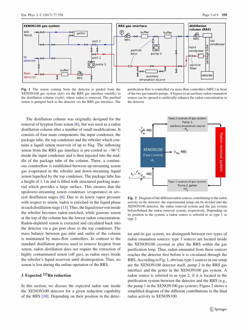
Fig. 2 Diagram of the different radon sources contributing to the radonactivity in the detector: the experimental setup can be divided into theXENON100 detector, the radon removal system and the gas systembefore/behind the radon removal system, respectively. Depending onits position in the system, a radon source is referred to as type 1 ortype 2
tor and its gas system, we distinguish between two types ofradon emanation sources: type 1 sources are located insidethe XENON100 cryostat or after the RRS within the gaspurification loop. Thus, radon emanated from these sourcesreaches the detector first before it is circulated through theRRS. According to Fig. 1, obvious type 1 sources in our setupare the XENON100 detector itself, pump 2 in the RRS gasinterface and the getter in the XENON100 gas system. Aradon source is referred to as type 2, if it is located in thepurification system between the detector and the RRS (e.g.,the pump 1 in the XENON100 gas system). Figure 2 shows asimplified diagram of the different contributions to the finalradon activity in XENON100.
123

358 Page 4 of 8 Eur. Phys. J. C (2017) 77 :358
In order to model the radon concentration inside the detec-tor, we assume a constant 222Rn production rate k1 by meansof emanation from type 1 sources. The total number of 222Rnatoms inside the detector, N (t), is continuously reduced dueto radioactive decay (t1/2 = 3.8 days) and is also removedby the purification flow. The latter gives rise to an effectiveexchange time texchange =: 1/ f with the flow parameter fbeing the ratio of the purification flow FXe in standard liters(sl) per second and the total amount of the xenon inventoryVXe in sl:
f = FXe
VXe. (1)
Additional radon (type 2) is added to the system at a certainrate k2 by the emanation in the gas system in front of the RRS.Inside the RRS the type 2 sources, as well as radon flushedfrom the detector with a radon particle flux f · N (t), arereduced by a factor R, expressing the reduction capability ofthe RRS. It is defined as the ratio of the radon concentrationat the inlet and outlet of the RRS,
R ≡ cin
cout. (2)
The remaining radon atoms re-enter the detector togetherwith additional type 1 sources k1 emanated from parts of thegas system behind the RRS, e.g., the additional pump 2 in theRRS gas interface and the XENON100 detector (see Fig. 2).The change in the number of radon atoms in the detector withtime is therefore described by the differential equation
dN (t)
dt= k1 − f · N (t) − λRn · N (t) + k2 + f · N (t)
R,
(3)
where f ·N (t) is again the effective radon particle flux out ofthe detector and λRn ·N (t) the decay of 222Rn using its decayconstant λRn = 2.1 × 10⁻⁶ s−1. The term (k2+ f ·N (t))/Rdescribes the number of radon particles that are not removedby the RRS. In this model, we assume the reduction factor Rto be constant, i.e., independent on the radon concentrationinvestigated here. Solving this differential equation with thestarting condition N (t = 0) = N0, where N0 is the numberof radon atoms before starting the removal, we find
N (t) = K
�+
(N0 − K
�
)· e−�·t ;
with K = k1 + k2
Rand � =
(λRn + f ·
(1 − 1
R
)).
(4)
For infinitely large times, the above relation simplifies to theequilibrium relation
Nequit→∞= K
�= k1 + k2
R
λRn + f · (1 − 1
R
) (5)
R→∞= k1
λRn + f, (6)
where the last step assumes an infinite purification capabilityR. Equation (6) shows that an ideal RRS can fully removethe type 2 sources. The reduction of type 1 sources is limitedby the exchange time 1/ f of the total xenon inventory andthus by the xenon purification flow. This limit for an idealRRS points to the importance of a high recirculation flow toremove radon from all emanation source types. Using Eq. (5),the radon reduction r inside the XENON100 detector for agiven R of the RRS can be defined as
r ≡ Nequi(R = 1)
Nequi(R). (7)
4 Data analysis
In order to measure the radon reduction due to cryogenicdistillation, we employ the XENON100 detector as a sensi-tive 222Rn monitor. The α-decays of 222Rn (5.5 MeV) and itsdirect daughter isotope 218Po (6.0 MeV) create a clear sig-nal in the primary scintillation light (S1) detected by thephotomultiplier tubes (PMTs) of the XENON100 detector[9,14].
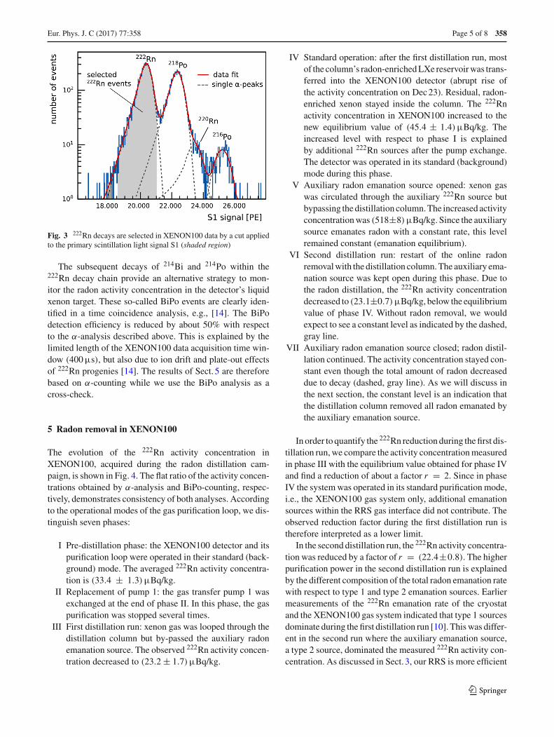
Due to PMT saturation effects, an S1 correction map,developed for high energy events in [14,15], is applied tothe data to remove light collection inhomogeneities. Werequire a minimum size for the secondary scintillation sig-nals (S2) of the selected interactions (>75% of 222Rn S2signals). This cut removes events suffering from incom-plete charge collection (e.g., surface events at the detector’swall). The α-events from 222Rn and 218Po are clearly iden-tified via their energies derived from the S1 signals (seeFig. 3). Furthermore, we observe the signatures of 220Rn andits direct daughter 216Po. The constant emanation of 220Rnin XENON100 has been investigated in [14,15], but wasfound to be negligible in this work. In our analysis, solely222Rn events are used to monitor the radon concentrationin XENON100. These are selected by applying an S1 cut,as shown in Fig. 3, which covers 96% of all 222Rn events.The overlap with the neighboring 218Po peak is determinedby a fit using crystal ball functions [16]. 8% of the selected222Rn events are misidentified 218Po decays. This is takeninto account when determining the 222Rn activity concen-tration. Being the direct daughter isotope with a half-life of3.1 min, 218Po follows the radon evolution. Consequently, themisidentified events do not impact the investigated reductionfactor.
123
Eur. Phys. J. C (2017) 77 :358 Page 5 of 8 358
Fig. 3 222Rn decays are selected in XENON100 data by a cut appliedto the primary scintillation light signal S1 (shaded region)
The subsequent decays of 214Bi and 214Po within the222Rn decay chain provide an alternative strategy to mon-itor the radon activity concentration in the detector’s liquidxenon target. These so-called BiPo events are clearly iden-tified in a time coincidence analysis, e.g., [14]. The BiPodetection efficiency is reduced by about 50% with respectto the α-analysis described above. This is explained by thelimited length of the XENON100 data acquisition time win-dow (400µs), but also due to ion drift and plate-out effectsof 222Rn progenies [14]. The results of Sect. 5 are thereforebased on α-counting while we use the BiPo analysis as across-check.
5 Radon removal in XENON100
The evolution of the 222Rn activity concentration inXENON100, acquired during the radon distillation cam-paign, is shown in Fig. 4. The flat ratio of the activity concen-trations obtained by α-analysis and BiPo-counting, respec-tively, demonstrates consistency of both analyses. Accordingto the operational modes of the gas purification loop, we dis-tinguish seven phases:
I Pre-distillation phase: the XENON100 detector and itspurification loop were operated in their standard (back-ground) mode. The averaged 222Rn activity concentra-tion is (33.4 ± 1.3)µBq/kg.
II Replacement of pump 1: the gas transfer pump 1 wasexchanged at the end of phase II. In this phase, the gaspurification was stopped several times.
III First distillation run: xenon gas was looped through thedistillation column but by-passed the auxiliary radonemanation source. The observed 222Rn activity concen-tration decreased to (23.2 ± 1.7)µBq/kg.
IV Standard operation: after the first distillation run, mostof the column’s radon-enriched LXe reservoir was trans-ferred into the XENON100 detector (abrupt rise ofthe activity concentration on Dec 23). Residual, radon-enriched xenon stayed inside the column. The 222Rnactivity concentration in XENON100 increased to thenew equilibrium value of (45.4 ± 1.4)µBq/kg. Theincreased level with respect to phase I is explainedby additional 222Rn sources after the pump exchange.The detector was operated in its standard (background)mode during this phase.
V Auxiliary radon emanation source opened: xenon gaswas circulated through the auxiliary 222Rn source butbypassing the distillation column. The increased activityconcentration was (518±8)µBq/kg. Since the auxiliarysource emanates radon with a constant rate, this levelremained constant (emanation equilibrium).
VI Second distillation run: restart of the online radonremoval with the distillation column. The auxiliary ema-nation source was kept open during this phase. Due tothe radon distillation, the 222Rn activity concentrationdecreased to (23.1±0.7)µBq/kg, below the equilibriumvalue of phase IV. Without radon removal, we wouldexpect to see a constant level as indicated by the dashed,gray line.
VII Auxiliary radon emanation source closed; radon distil-lation continued. The activity concentration stayed con-stant even though the total amount of radon decreaseddue to decay (dashed, gray line). As we will discuss inthe next section, the constant level is an indication thatthe distillation column removed all radon emanated bythe auxiliary emanation source.
In order to quantify the 222Rn reduction during the first dis-tillation run, we compare the activity concentration measuredin phase III with the equilibrium value obtained for phase IVand find a reduction of about a factor r = 2. Since in phaseIV the system was operated in its standard purification mode,i.e., the XENON100 gas system only, additional emanationsources within the RRS gas interface did not contribute. Theobserved reduction factor during the first distillation run istherefore interpreted as a lower limit.
In the second distillation run, the 222Rn activity concentra-tion was reduced by a factor of r = (22.4±0.8). The higherpurification power in the second distillation run is explainedby the different composition of the total radon emanation ratewith respect to type 1 and type 2 emanation sources. Earliermeasurements of the 222Rn emanation rate of the cryostatand the XENON100 gas system indicated that type 1 sourcesdominate during the first distillation run [10]. This was differ-ent in the second run where the auxiliary emanation source,a type 2 source, dominated the measured 222Rn activity con-centration. As discussed in Sect. 3, our RRS is more efficient
123

358 Page 6 of 8 Eur. Phys. J. C (2017) 77 :358
Fig. 4 Top panel Evolution of the 222Rn activity concentration inXENON100 during the radon distillation campaign. The seven differ-ent phases (roman numerals) show different operational modes of the
detector. The gray dashed line shows the expected 222Rn concentra-tion in the absence of the RRS. Bottom panel Comparison of the 222Rnactivity as determined by the α-counting method and the BiPo analysis
for type 2 sources while the reduction of type 1 sources is sup-pressed by the limited purification flow of FXe = 4.5 slpm.
6 Reduction capability of the distillation column
In this section, we fit our data using the rate equation modeldeveloped in Sect. 3. Doing so, we investigate the radonremoval capability of the distillation column, expressed bythe reduction factor R (defined in Eq. (2)). We emphasize thatdue to the limited gas flow, this reduction factor is not equiv-alent to the observed radon reduction r (defined in Eq. (7))inside the detector investigated in the previous section. Forthis analysis we focus on the data from phases V–VII whichwere acquired under stable conditions.
The rate equation model is based on the assumption ofa homogeneous radon distribution inside the detector at anytime. We justify this assumption using data acquired whenopening the auxiliary radon source at the beginning of phaseV. After about two hours, a higher equilibrium in the α-rate, originating from 222Rn and 218Po, is observed (Fig. 5,bottom). At any time, 222Rn events are distributed homoge-neously inside the sensitive volume. No concentration gradi-ents are found in the Z-position (Fig. 5, top) nor in the radialposition.
Since the auxiliary emanation source is of type 2 and canbe switched off (see phase VII), we treat it separately inEq. (4). We define
Fig. 5 Combined 222Rn and 218Po α-decays before and after openingthe auxiliary radon emanation source. The α-rate saturates about 2 hafter opening the source (bottom). The spatial distribution of the eventsis homogeneous at any time (top)
Ks = k1 + k2 + ksR
and K = k1 + k2
R, (8)
where ks refers to the emanation of the auxiliary source whilek2 describes all other type 2 sources within the system. In
123
Eur. Phys. J. C (2017) 77 :358 Page 7 of 8 358
Table 1 Parameters obtained from fitting the rate equation model,Eq. (9) (a–c), to phases V–VII
c1 (type 1) (53 ± 4)µBq/kg
c2 (type 2) (23 ± 6)µBq/kg
cs (aux. em. source) (442 ± 10)µBq/kg
f (flow parameter) (3.1 ± 0.2) × 10−6 s−1
R (RRS reduction factor) >27 (95% C.L.)
χ2/ndf 37.73/28
order to fit the model to the data, we solve Eq. (3) for thecorresponding starting condition for each operational phase.The number of 222Rn atoms for phases V–VII is given by
NV(t) = (k1 + k2 + ks) · λ−1Rn = const., (9a)
NVI(t) = Ks
�+
(NV(tVI) − Ks
�
)· e−�·(t−tVI), (9b)
NVII(t) = K
�+
(NVI(tVII) − K
�
)· e−�·(t−tVII), (9c)
where tVI and tVII are the starting times of phases VI and VII,respectively. The factor � has been defined in Eq. (4). In thefollowing, we use the corresponding 222Rn activity concen-trations (c1, c2 and cs) instead of the rates k1, k2 and ks . Thisallows for better comparison with the data shown in Fig. 4.
The fit results, obtained for phases V–VII, are given inTable 1 and Fig. 6 (red curve). The radon contribution fromtype 1 sources is determined to be c1 = (53±4)µBq/kg. Thisis a higher value than the 222Rn activity concentration mea-sured during phase IV, before the second distillation run. Weconclude that the RRS gas interface houses additional type 1sources, e.g., pump 2 after the distillation column (see Fig. 1).
For this fit, we used cs > 400µBq/kg as a conservativelower limit for the strength of the auxiliary emanation source.This constraint is based on the α-rate monitored when open-ing the source at the beginning of phase V. As shown in Fig. 5,we can assign about 80% of the increased activity to the aux-iliary source. From the fit, we find cs = (442 ± 10)µBq/kg.The residual type 2 emanation sources are determined to bec2 = (23 ± 6)µBq/kg. For the flow parameter we obtainf = (3.1±0.2)×10−6 s−1. We can translate the result for finto a gas purification flow of FXe = (5.2 ± 0.4) slpm usingthe detector’s total LXe-mass of mXe = (158 ± 3)kg dur-ing the distillation campaign. This is a slightly higher massflow than the measured value of FXe = (4.50 ± 0.05) slpmobtained from the flow meters in the purification loop. Fromthis result we conclude that only (87 ± 5)% of the liquidxenon target are effectively purified, assuming a homoge-neous radon distribution inside the detector, or that the radonmixes only with this fraction of the total xenon budget.
The best fit value of the distillation column’s reductionfactor is R = 91 (minimum χ2). Since R is only poorly
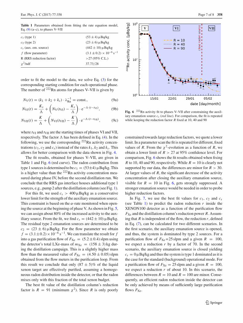
Fig. 6 222Rn activity fit to phases V–VII after constraining the auxil-iary emanation source cs (red line). For comparison, the fit is repeatedwhile keeping the reduction factor R fixed at 10, 40 and 90
constrained towards large reduction factors, we quote a lowerlimit. In a parameter scan the fit is repeated for different, fixedvalues of R. From the χ2-evolution as a function of R, weobtain a lower limit of R > 27 at 95% confidence level. Forcomparison, Fig. 6 shows the fit results obtained when fixingR to 10, 40 and 90, respectively. While R = 10 is clearly notsupported by our data, the differences are minor for R > 30.At larger values of R, the significant decrease of the activityconcentration after closing the auxiliary emanation source,visible for R = 10 in Fig. 6, gets strongly suppressed. Astronger emanation source would be needed in order to probehigher reduction factors.
In Fig. 7, we use the best fit values for c1, c2 and cs(see Table 1) to predict the radon reduction r inside theXENON100 detector as a function of the purification flowFXe and the distillation column’s reduction power R. Assum-ing that R is independent of the flow, the reduction r , definedin Eq. (7), can be calculated for two different scenarios. Inthe first scenario, the auxiliary emanation source is opened,and thus, the system is dominated by type 2 sources. For apurification flow of FXe = 25 slpm and a given R = 100,we expect a reduction r by a factor of 70. In the secondscenario, the auxiliary emanation source is closed yieldingcs = 0µBq/kg and thus the system is type 1 dominated as it isthe case for the standard (background) operational mode. Fora purification flow of FXe = 25 slpm and a given R = 100,we expect a reduction r of about 10. In this scenario, thedifferences between R = 10 and R = 100 are minor. Conse-quently, an efficient radon reduction inside the detector canbe only achieved by means of sufficiently large purificationflows FXe.
123

358 Page 8 of 8 Eur. Phys. J. C (2017) 77 :358
Fig. 7 Expected 222Rn reduction r (Eq. (7)) inside the XENON100detector as a function of the purification flow FXe. We distinguishbetween the scenarios having the auxiliary emanation source opened(type 2 dominated emanation) and having it closed (type 1 dominatedemanation). The reduction r is predicted for different reduction factorsR for the radon removal system
7 Summary and conclusions
After achieving the dark matter science goal with XENON100,the gas purification system of the detector was extendedwith a cryogenic distillation column, operated as a 222Rnremoval system. We significantly reduced the 222Rn activityconcentration without any xenon losses (off-gas). The radonreduction capability of the distillation column, defined as theratio of the 222Rn concentration in the xenon gas before andafter distillation, respectively, was determined to be R > 27(95% C.L.).
These results show the potential of continuous cryogenicdistillation as a xenon purification method to reduce 222Rninduced backgrounds for upcoming liquid xenon detectors.We have shown that the available purification flow is oneof the limiting factors for the efficient removal of type 1222Rn emanation sources described in Sect. 3. For upcominglarge scale experiments such as XENON1T [4], XENONnT[4] and DARWIN [17], the design and construction of aradon distillation column achieving purification flows up to200 slpm is currently under investigation.
Acknowledgements We gratefully acknowledge support from theNational Science Foundation, Swiss National Science Foundation,Deutsche Forschungsgemeinschaft, Max Planck Gesellschaft, GermanMinistry for Education and Research, Foundation for FundamentalResearch on Matter, Weizmann Institute of Science, I-CORE, InitialTraining Network Invisibles (Marie Curie Actions, PITNGA-2011-289442), Fundacao para a Ciencia e a Tecnologia, Region des Paysde la Loire, Knut and Alice Wallenberg Foundation, Kavli Foundation,and Istituto Nazionale di Fisica Nucleare. We are grateful to Labora-
tori Nazionali del Gran Sasso for hosting and supporting the XENONproject.
Open Access This article is distributed under the terms of the CreativeCommons Attribution 4.0 International License (http://creativecommons.org/licenses/by/4.0/), which permits unrestricted use, distribution,and reproduction in any medium, provided you give appropriate creditto the original author(s) and the source, provide a link to the CreativeCommons license, and indicate if changes were made.Funded by SCOAP3.
References
1. E. Aprile et al., (XENON100), Study of the electromagnetic back-ground in the XENON100 experiment. Phys. Rev. D 83, 082001(2011). arXiv:1101.3866
2. D.S. Akerib et al., (LUX), Radiogenic and muon-induced back-grounds in the LUX dark matter detector. Astropart. Phys. 62, 33(2015). arXiv:1403.1299
3. A. Tan et al., (PandaX-II), Dark matter results from first 98.7-daydata of PandaX-II experiment. Phys. Rev. Lett. 117, 121303 (2016).arXiv:1607.07400
4. E. Aprile et al., (XENON1T), Physics reach of the XENON1T darkmatter experiment. JCAP 04, 027 (2016). arXiv:1512.07501
5. J.B. Albert et al., (EXO-200), Investigation of radioactivity-induced backgrounds in EXO-200. Phys. Rev. C92, 015503 (2015).arXiv:1503.06241
6. E. Aprile et al. (XENON1T), Removing krypton from xenon bycryogenic distillation to the ppq level. Eur. Phys. J. C 77, 275(2017). arXiv:1612.04284.
7. K. Abe et al., (XMASS), Distillation of liquid xenon to removekrypton. Astropart. Phys. 31, 290 (2009). arXiv:0809.4413
8. Z. Wang et al., Design and construction of a cryogenic distillationdevice for removal of krypton for liquid xenon dark matter detec-tors. Rev. Sci. Instrum. 85, 015116 (2014). doi:10.1063/1.4861537
9. E. Aprile et al., (XENON100), The XENON100 dark matter exper-iment. Astropart. Phys. 35, 573 (2012). arXiv:1107.2155
10. S. Lindemann, Intrinsic 85Kr and 222Rn backgrounds in theXENON dark matter search. PhD Dissertation University of Hei-delberg (2013). http://archiv.ub.uni-heidelberg.de/volltextserver/15725/
11. Aprile et al., (XENON Collaboration), Radon emanation measure-ments (in progress)
12. K. Abe et al., (XMASS), Radon removal from gaseous xenon withactivated charcoal. Nucl. Instrum. Meth. A 661, 50 (2012). doi:10.1016/j.nima.2011.09.051
13. S. Bruenner et al., Radon depletion in xenon boil-off gas. Eur. Phys.J. C 77, 143 (2017). arXiv:1611.03737
14. M. Weber, Gentle neutron signals and noble background in theXENON100 dark matter search experiment. PhD DissertationUniversity of Heidelberg (2013). http://www.ub.uni-heidelberg.de/archiv/15155
15. E. Aprile et al. (XENON100), Results from a calibration ofXENON100 using a source of dissolved radon-220 Phys. Rev. D95, 072008 (2017). arXiv:1611.03585
16. J. E. Gaiser, PhD dissertation (appendix-F), Stanford University(1982). http://www.slac.stanford.edu/cgi-wrap/getdoc/slac-r-255.pdf
17. J. Aalbers et al. (DARWIN), DARWIN: towards the ultimate darkmatter detector. JCAP 1611(11), 017 (2016). arXiv:1606.07001
123

![Data Distillation: Towards Omni-Supervised Learning · Data Distillation model A model A Figure 1. Model Distillation [18] vs. Data Distillation. In data distillation, ensembled predictions](https://img.dokumen.tips/doc/110x75/60a237adb93b13457117b793/data-distillation-towards-omni-supervised-learning-data-distillation-model-a-model.jpg)


![Cosmogenic*Ac,vaon* in*DMIce* - Yale Universityneutrino.physics.wisc.edu/teaching/PHYS736_2011Spring/project... · EDELWEISS XENON100 (2010) XENON100 (2011) ... XENON100 (2010) [7]](https://img.dokumen.tips/doc/110x75/5b894f057f8b9ae7298c19c5/cosmogenicacvaon-indmice-yale-edelweiss-xenon100-2010-xenon100-2011.jpg)