Embed Size (px)
Citation preview

The Riello RDB series of one stage light oil and kerosene burners is available in 8 basicmodels, with an output ranging from 16,8 to 120 kW, in three different structures.The models are available in light oil and kerosene versions, conventional flue and balancedflue, with or without the fuel pre-heater fitted.A new model has been specifically designed to meet the increasing trends towards highpressure working field demand.These models are distinguished by their compact size.All the models use the same components designed by Riello for the RDB series. The highquality level guarantees safe working.In developing these burners, special attention was paid to reducing noise, to the ease ofinstallation and adjustment, to obtaining the smallest size possible to fit into any sort ofboiler available on the market.All the models are approved by the EN 267 European Standard and conform to EuropeanDirectives for EMC, Low Voltage, Machinery and Boiler Efficiency.All the RDB burners are fired before leaving the factory.
TS0008UK03
ONE STAGE LIGHT OIL AND KEROSENE BURNERSRDB SERIES RDB1-1R 16,8 ÷ 40,6 kW
RDB2-2R 24,0 ÷ 46,2 kWRDB2.1-2.1R 21,0 ÷ 54,0 kWRDB2.2-2.2R 21,0 ÷ 51,0 kWRDB3 35,6 ÷ 68,7 kWRDB3.2 41,0 ÷ 120,0 kWRDB4 55,7 ÷ 113,0 kW
www.gotoplumbing.co.uk - Boiler & Appliance Manuals

TECHNICAL DATA
RDB1 RDB1R RDB2 RDB2R RDB3 RDB4RDB2.1RRDB2.1
Appro
val
Fuel
/ ai
r d
ata
Ele
ctri
cal d
ata
Em
issi
on
s
type
s
kW
Mcal/h
kg/h
°C min./max.
kWh/kg
kcal/kg
mm2/s (cSt)
type
kg/h
bar
max. °C
type
max. °C
Ph/Hz/V
Ph/Hz/V
type
kW
kW
kW
IP
kW
A
A
IP
kW
A
A
IP
type
V1 - V2
I1 - I2
dB (A)
W
mg/kWh
N° Bacharach
mg/kWh
mg/kWh
Model
Burner operation mode
Modulation ratio at max. output
Servomotor.
run time
Heat output
Working temperature
Net calorific value
Viscosity
Pump.
delivery
Atomised pressure
Fuel temperature
Fuel pre-heater
Fan
Air temperature
Electrical supply
Auxiliary electrical supply
Control box
Total electrical power
Auxiliary electrical power
Heaters electrical power
Protection level
Pump motor electrical power
Rated pump motor current
Pump motor start up current
Pump motor protection level
Fan motor electrical power
Rated fan motor current
Fan motor start up current
Fan motor protection level
Ignition transformer
Operation
Sound pressure
Sound power
CO emission
Grade of smoke indicator
CxHy emission
NOx emission
Directive
Conforming to
Certification
RDB2.2RRDB2.2
One stage
--
--
--
16,8 - 26,3 21,6 - 40,6 24 - 38,3 33,2 - 46,2 21 - 42 33 - 54 21 - 41,5 33,5 - 51 35,6 - 68,7 41 - 120 55,7 - 113
14,4 - 22,6 18,6 - 34,9 20,6 - 32,9 28,5 - 39,7 18 - 36,1 28,4 - 45,9 18,1 - 35,7 28,9 - 44 30,6 - 59 35,26 - 103,2 48 - 97,2
1,4 - 2,2 1,8 - 3,4 2 - 3,2 2,8 - 39 1,8 - 3,5 2,8 - 4,5 1,8 - 3,5 2,9 - 4,3 3 - 5,8 3,5 - 10 4,7 - 9,5
0/40
11,9
10.200
4 ÷ 6 (at 20°C) for light oil models / 1,5 ÷ 6 (at 20°C) for kerosene models
R.B.L.
30 (at 12 bar)
8 ÷ 15
50
NO YES NO YES NO YES NO YES NO NO NO
centrifugal with forward curve blades
40
1/50/230 ±10%
--
R.B.L.535 R.B.L.535R R.B.L.535 R.B.L.535R R.B.L.535 R.B.L.535R R.B.L.535 R.B.L.535R R.B.L.535 R.B.L.535 R.B.L.535RSE/LD SE/LD SE/LD SE/LD SE/LD SE/LD SE/LD SE/LD SE/LD SE/LD SE/LD
0,115 0,175 0,125 0,175 0,124 0,174 0,124 0,174 0,16 0,16 0,16
--
-- 0,055/0,025 -- 0,055 -- 0,055 -- 0,055 -- -- --
40
--
--
--
--
0,09 0,15
0,75 1,3
3 4,3
20
Incorporated in the control box
( -- ) - 8 kV
( -- ) - 16 mA
Intermittent (at least one stop every 24 h)
60 60 61,5 61,5 62 62 62 62 63 63 66
--
< 30
< 1
< 10 (after the first 20s)
< 200 < 185 < 200
89/336/EEC, 73/23/EEC, 98/37/EEC, 92/42/EEC
EN 267
CE-0036 0316/01 CE-0036 0326/01CE-0036 0316/01 CE-0036 0316/01 CE-0036 0316/01 CE-0036 0316/01 CE-0036 0316/01 CE-0036 0316/01 CE-0036 0275/99 in progress CE-0036 0274/99
RDB3.2
Reference conditions:Temperature: 20 °CPressure: 1013 mbarAltitude: 0 m a.s.l.Noise measured at a distance of 1 meter.
Since the Company is constantly engaged in the production improvement, the aesthetic and dimensional features, thetechnical data, the equipment and the accessories can be changed.This document contains confidential and proprietary information of RIELLO S.p.A. Unless authorised, this information shallnot be divulged, nor duplicated in whole or in part.
2
www.gotoplumbing.co.uk - Boiler & Appliance Manuals

FIRING RATES
For every models (e.g. RDB1) are available many combustion heads that allows to optimizethe working field.
0
2
kW20
0
20
30
40
1
4
400 60 80 100 120
3
10
RDB3 RDB4
RDB3.2
hP
a (m
bar
)
mm
H2O
Test conditions conforming to EN 267:Temperature: 20°CPressure: 1013 mbarAltitude: 0 m a.s.l.
Useful working field forchoosing the burner
Firing rate in progress
3
1086420 kg/h
0
0,5
0
5
10
15
1
1,5
RDB1RDB1R
hP
a (m
bar
)
mm
H2O
kW20 400 6010 30 50
420 1 3 5 kg/h
0
0,5
0
5
10
15
1
1,5
420 1 3 5
RDB2RRDB2
hP
a (m
bar
)
mm
H2O
kW20 400 6010 30 50
kg/h
420 1 3 50
2
1
5
3
4
0
10
20
40
30
50
RDB2.1RRDB2.1
RDB2.2 RDB2.2R
hP
a (m
bar
)
mm
H2O
kW20 400 6010 30 50
kg/h
www.gotoplumbing.co.uk - Boiler & Appliance Manuals

HYDRAULIC CIRCUIT
FUEL SUPPLY
All the models have a Riello geared pump with safety valve on thereturn circuit, and some are fitted with a fuel pre-heater.The kerosene models have a special kerosene pump, whichguarantees reliable operations with this type of fuel.
RDB - RDB R
Fuel pump
S
1
VR(NO)
2
T
S
VR(NO)
1
2
PH
U
Pump with filter and pressure regulator onthe delivery pipe
Oil return valve normally open
Oil input pipe to the nozzle
Oil return pipe from the regulator
Oil pre-heater with thermostat (where provided)
Nozzle
4
UPH
www.gotoplumbing.co.uk - Boiler & Appliance Manuals

SELECTING THE FUEL SUPPLY LINES
The fuel feed must be completed with the safety devices required by the local regulations in force.
The table shows the choice of piping diameter for the various burners, depending on the differencein the height between the burner and the tank and the distance between them.
6
Type of system that can be installed
Pipe size
H (m)
0
0,5
1,0
1,5
2,0
3,0
3,5
Ø8mm
L max (m)
35
30
25
20
15
8
6
Ø10mm
L max (m)
100
100
100
90
70
30
20
Ø8mm
L max (m)
-
10
20
40
60
-
-
Ø10mm
L max (m)
-
20
40
80
100
-
-
Type A system
MAXIMUM EQUIVALENT LENGTH OF THE PIPEWORK L[m]
Type B system
Difference in height
Internal pipe diameter
Difference in height ≤ 4 m
Burner
Pump
Filter
Shut-off solenoid valve
Suction pipework
Bottom valve
Return pipework
H
Ø
P
1
2
3
4
5
6
7
HP
H
1
4
10 cm2
3
7 5 H
P
H
1
4
10 cm2
5
3
7
A
6
3
B
H
P
1
2
43
2
3
1
5
www.gotoplumbing.co.uk - Boiler & Appliance Manuals

COMBUSTION HEAD
VENTILATION
The RDB series has been designed anddeveloped paying special attention toreducing noise levels, while guaranteeinghigh performance of pressure and airdelivery, inspite of their compact size.
There are several types of available combustion heads, to optimise allthe various burner-boiler matchings.A simple adjustment to the combustion head (where fitted) allows adaptingsecondary air to the burner output.
Adjustable combustion head
Air suction
Dimensions of the flame
Fixed combustion head
Special attention has also been paid to the air-tightnessof the air circuit (this is also checked during the functionaltests to the burners on the production line); the air-tightnessis guaranteed by special technical solutions and seals, andis always conserved after any servicing operations.All the conventional flue models can be easily convertedto balanced flue, and vice versa, by using a special kit.
Example:Burner thermal output = 350 kW;L flame (m) = 1,2 m (medium value);D flame (m) = 0,6 m (medium value)
D
L
Burner output (kW)
Flam
e le
ng
th (
m)
Flam
e d
iam
eter
(m
)
0 200
1
100 300
2
400 500
0 0
0,5
1L max
L min
D max
D min
6
www.gotoplumbing.co.uk - Boiler & Appliance Manuals

ADJUSTMENT
All these models are one stage operation; the special profile on theair-damper and its micrometric adjustment, ensure precise workingeven at the lowest output levels of the burner.
BURNER OPERATION MODE
* only model with pre-heater
Correct operation
0s The burner begins the ignition cycle.0s-12s Pre-purge with the air damper open.12s Ignition.
If the pre-heater is fitted there is a further delay before pre-purge;this delay can reach 150s depending on room and fuel temperatures.
Lock-out due to ignition failureIf the flame does not light within the safety limit (~5s) the burnerlocks-out.The lock-out is shown by a led on the appliance.
START UP CYCLE
0 ÷ 150 s ~12 s
TR* Pre-heater
M
V
Ignitiontransformer
Lock-out led
Normal
time (s)
Ou
tpu
tC
hec
ked
var
iab
le bar°C
ON
OFF
time
time
ON
OFF
“One stage” operation
Air damper adjustmentAir damper
7
www.gotoplumbing.co.uk - Boiler & Appliance Manuals

Electrical connections must be made by qualified and skilledpersonnel in conformity with the local regulations in force.The terminal board is incorporated in the burner control boxand connection is easy following the clear instructions that aregiven.
WIRING DIAGRAMS
Appliance fitted with an ignition transformer
The following table shows the supply lead sections and types of fuse to be used.
“ONE STAGE” OPERATION
RDB1-1RModel
A
mm2
FL
230V
61
RDB2-2R
230V
61
RDB3
230V
T61
RDB4
230V
T61
F = Fuse L = Lead section
S - Lock out ledTL - Regulation thermostatTS - Safety thermostat (manual reset)F - Fuse
RDB2.1-2.1R
230V
T61
RDB2.2-2.2R
230V
T61
L2NL1
F
TS
S
L N
~ 50Hz 230V
TL
RDB3.2
230V
T61
ϑ
ϑ
8
www.gotoplumbing.co.uk - Boiler & Appliance Manuals

EMISSIONS
The emission data havebeen measured in thevar ious models a tmaximum output, inconformity with EN 267standard.
NO2 EMISSIONS
mg
/kW
h
80RDB1 RDB1R RDB2
CO EMISSIONS
mg
/kW
h
0
5
10
15
20
30
SOUND EMISSIONS (sound pressure)
dB
(A)
5456
72
RDB2R RDB3
100
120
140
160
180
200
220
25
58
60
62
64
66
68
70
RDB4
RDB1 RDB1R RDB2 RDB2R RDB3 RDB4
RDB1 RDB1R RDB2 RDB2R RDB3 RDB4
35
RDB2.1 RDB2.1R
RDB2.1 RDB2.1R
RDB2.1 RDB2.1R
RDB2.2 RDB2.2R
RDB2.2 RDB2.2R
RDB2.2 RDB2.2R
RDB3.2
RDB3.2
RDB3.2
9
www.gotoplumbing.co.uk - Boiler & Appliance Manuals

OVERALL DIMENSIONS (mm)
These models are distinguished by their reduced size, in relationto their output, which means they can be fitted to any boiler onthe market.
X
Z
Y
PACKAGING
BURNER
BURNER-BOILER MOUNTING FLANGE
RDB1-1R - RDB2-2R - RDB2.1-2.1R - RDB2.2-2.2R RDB3 - RDB3.2 - RDB4
Z
295295295295355355355
RDB1-1R - RDB2-2RRDB2.1-2.1R - RDB2.2-2.2R
RDB3 - RDB3.2RDB4
L
A
EF
ID
J
A
D
EF
I
L
Model A HD I
RDB1-1R
RDB2-2R
RDB2.1-2.1R
RDB2.2-2.2R
RDB3
RDB3.2
RDB4
276276286286325325325
168168168168204204204
230230230230268268268
76-8676-86
777778
69,5111
L20202020303030
E202202202202253253253
89-9089-90
85858895105
F J75757575757575
Model
RDB1-1R
RDB2-2R
RDB2.1-2.1R
RDB2.2-2.2R
RDB3
RDB3.2
RDB4
X Y kg
395395395395435435435
305305305305360360360
11111111151515
Model L M ON
RDB1-1R
RDB2-2R
RDB2.1-2.1R
RDB2.2-2.2R
RDB3
RDB3.2
RDB4
150150150150168168168
130130130130140140140
180180180180189189189
72727272838383
91919191106106106
P
72727272838383
Q
J
10
H H
M
11
L
N
Q
P45°
45°
M
11
L
N
Q
P45°
45°
OO
www.gotoplumbing.co.uk - Boiler & Appliance Manuals

INSTALLATION DESCRIPTION
Skilled and qualified personnel must perform installation, startup and maintenance.A nozzle is fitted to the burner and used for fire tests in thefactory. If necessary, change the nozzle on the basis of themaximum output of the boiler.All operations must be carried out as described in the technicalhandbook supplied with the burner.
Head setting area is easily accessible and the operationis simple thanks to a graduated scale.
RDB series burners can be adjusted from the back ofthe burner just using a single tool; the air damper iseasily adjustable (thanks to a micrometric screw and aposition indicator) without removing the burner cover.
In models RDB3 and RDB4, the maintenance positionis easily carried out by hooking the burner to the flange,after removing it from the fixing screws.
Maintenance is easy because all the components,including the combustion head, are easily accessed byjust unscrewing a single nut.
The main components - the control box, motor andpump - are outside the air circuit, thus avoiding anyrisk of oil build up inside the circuit.
All the electrical components are connected by socket-plugs and they are easy to reach for controls.
BURNER SETTING
MAINTENANCE
11
www.gotoplumbing.co.uk - Boiler & Appliance Manuals

BURNER ACCESSORIES
Balanced-conventional flue conversion kit
All the RDB series models are easily converted from conventionalflue to balanced flue, by replacing the plastic screen on the air intakewith the connector for the air supply pipe.
Balanced fluekit code
3062774
3062774
RDB1-1R - RDB2-2RRDB2.1-2.1R - RDB2.2-2.2R
RDB3 - RDB4
Burner
Balanced-conventional flue conversion kit
The reverse operation can be carried out on all the models from balanced flue to conventional flueburner, by replacing the connector on the air supply pipe with the plastic screen on the air intake.
Conventional fluekit code
3062775
3062876
Tester
The tester controls the correct working of the burner components in the RDB series. It can be fittedto all the models, with or without pre-heater.It is made up of two parts: a control instrument and a "control box" which replaces and simulates theone on the burner.This tester is very simple to use: just replace the burner control box with the tester to check correctworking of the motor, valve, pre-heater and flame probe (only photo-resistance).This device has a display showing the levels that have been measured, a selection switch for selectingthe component to be tested and four switches to be used in the various working stages of the burner.
Kit code
3087216RDB - RDB R
Burner
Tester
Measurements
MOTOR
Direct testing
Main voltage(230 V)
VALVE
Pre-heatercurrent consumption
The switch feeds the motor.
The switch feeds electromagnetic winding of thecoil. A red led signals excitation stage, and a greenled signals retainer stage.
PRE-HEATER
Secondary voltage(low voltage)
The switch feeds the light oil pre-heater; a greenled signals the thermostat cut-in.
TRANSFORMER
Photo-resistancecurrent consumption
The switch feeds the firing transformer inside thecontrol box and excites the oil valve.
M L1-NV
V M
A
A
12
www.gotoplumbing.co.uk - Boiler & Appliance Manuals
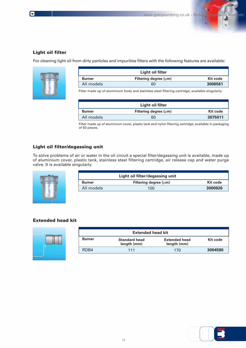
Extended head kit
Kit code
3004590RDB4 111
Standard headlength (mm)
170
Extended headlength (mm)
Kit codeBurner
3006561All modelsFiltering degree (μm)
60
Filter made up of aluminium body and stainless steel filtering cartridge; available singularly.
For cleaning light oil from dirty particles and impurities filters with the following features are available:
Light oil filter
Light oil filter/degassing unit
To solve problems of air or water in the oil circuit a special filter/degassing unit is available, made upof aluminium cover, plastic tank, stainless steel filtering cartridge, air release cap and water purgevalve. It is available singularly.
Burner
Extended head kit
Burner
Light oil filter/degassing unit
Kit code
3000926All modelsFiltering degree (μm)
100
Light oil filter
Light oil filter
Filter made up of aluminium cover, plastic tank and nylon filtering cartridge; available in packagingof 50 pieces.
3075011All models 60Kit codeBurner Filtering degree (μm)
13
www.gotoplumbing.co.uk - Boiler & Appliance Manuals

A special index will help you choose the right burnerfrom the available RDB models.There is also a clear and detailed product specificationand description.
RDB1-1R 1/230/50RDB2-2R 1/230/50RDB2.1-2.1R 1/230/50RDB2.2-2.2R 1/230/50RDB3 1/230/50RDB3.2 1/230/50RDB4 1/230/50
Size
DESIGNATION OF SERIES
1 RRDB
Series: RDB
Possible variations: R Light-oil pre-heater
AVAILABLE BURNER MODEL
SPECIFICATION
1/230/50
Electrical supply to the system: 1/230/50 1/230V/50Hz
14
www.gotoplumbing.co.uk - Boiler & Appliance Manuals

PRODUCT SPECIFICATION
Burner
Completely automatic monobloc light oil and kerosene burners, with single-stage operation fittedwith:- Fan with forward inclined blades- Air damper with external adjustment, with no need to remove the cover- Air-tight air circuit, also available in the balanced flue version- Single phase electric motor 230 V, 50 Hz- Combustion head fitted with:
- stainless steel head cone, resistant to high temperatures- ignition electrodes- flame stability disk
- Geared pump (specific version for kerosene) for fuel supply, fitted with filter- pressure regulator- attachments for fitting a pressure gauge and vacuum meter
- internal by-pass for preparing for single-pipe installations- Fuel feed solenoid valve incorporated in the pump- Photocell for flame detection- Electronic flame control equipment- Protective filter against radio interference- Light oil nozzle- IP 40 protection level- Fuel pre-heater (optional).
Approval:- EN 267 standard- for RDB 2.2 - 2.2R in progress.
Conforming to:- Directive 89/336/EEC (electromagnetic compatibility)- Directive 73/23/EEC (low voltage)- Directive 98/37/EEC (machinery)- Directive 92/42/EEC (efficiency).
Standard equipment:- Two flexible pipes for connection to the light oil supply line- Two nipples for connection to the pump- Flange, screws and nuts for fixing- Thermal screen- Air intake- Protection grill- Exagonal key- Instruction handbook for installation, use and maintenance- Spare parts list.
Available accessories to be ordered separately:- Balanced-conventional flue conversion kit- Tester- Light oil filter- Light oil filter/ degassing unit- Extended head kit (only for RDB4).
15
www.gotoplumbing.co.uk - Boiler & Appliance Manuals

RIELLO S.p.A. - Via Ing. Pilade Riello, 5 - 37048 San Pietro di Legnago (VR) ItalyTel. ++39.0442630111 - Fax ++39.044221980
Internet: http://www.rielloburners.com - E-mail: [email protected] 9001 Cert. n. 0061
Since the Company is constantly engaged in the production improvement, the aesthetic anddimensional features, the technical data, the equipment and the accessories can be changed.
This document contains confidential and proprietary information of RIELLO S.p.A.Unless authorised, this information shall not be divulged, nor duplicated in whole or in part.
www.gotoplumbing.co.uk - Boiler & Appliance Manuals