Embed Size (px)
Citation preview

PRESS T/G SERIES P 140 T/G 380/830 ÷ 1660 kWP 200 T/G 557/1186 ÷ 2372 kWP 300 T/G 712/1779 ÷ 3560 kWP 450 T/G 890/2670 ÷ 5340 kW
TS0038UK03
THREE STAGE LIGHT OIL BURNERS
The PRESS T/G series of burners covers a firing range from 830 to 5340 kW.Available in 4 different models, this burners are particularly well suited for matching withpressurized chamber boilers.For their characteristics, they find application in big civil plants for domestic heating or inindustrial applications where thermal load is repetitive and predictable.An hydraulic ram exclusive system, with 3 adjustable positions, regulates dampers opening,allowing air passage in relation to output required: in this way flame stability is optimizedin every working point, with micro-regulation available.The burners are fitted with a microprocessor control panel which supplies indication ofoperation and diagnosis of fault cause.

TECHNICAL DATAFu
el /
air
dat
aE
lect
rica
l d
ata
Em
issi
on
sA
ppro
val
type
s
kW
Mcal/h
kg/h
°C min./max.
kWh/kg
kcal/kg
mm2/s (cSt)
type
kg/h
bar
max. °C
type
max. °C
Ph/Hz/V
Ph/Hz/V
type
kW
kW
kW
IP
kW
A
A
IP
kW
A
A
IP
type
V1 - V2
I1 - I2
dBA
W
mg/kWh
N° Bacharach
mg/kWh
mg/kWh
Model
Burner operation mode
Modulation ratio at max. output
Servomotor run time
Heat output
Working temperature
Net calorific value
Viscosity
Pump delivery
Atomised pressure
Fuel temperature
Fuel pre-heater
Fan
Air temperature
Electrical supply
Auxiliary electrical supply
Control box
Total electrical power
Auxiliary electrical power
Heaters electrical power
Protection level
Pump motor electrical power
Rated pump motor current
Pump motor start up current
Pump motor protection level
Fan motor electrical power
Rated fan motor current
Fan motor start up current
Fan motor protection level
Ignition trasformer
Operation
Sound pressure
Sound power
CO emission
Grade of smoke indicator
CxHy emission
NOx emission
Directive
Conforming to
Certification
89/336 (2004/108) - 73/23 (2006/95)
- 92/42 - 98/37 EC
Three stage
3 : 1
--
--
0/40
11,86
10200
4 ÷ 6 (at 20°C)
12
50
NO
Centrifugal with forward curve blades
60
3N/50/400~(±10%) 3/50/230~(±10%)
1/50/230 (±10%)
RMO
--
40
--
--
--
--
55
230 V - 2x6 kV
2,3 A - 35 mA
Intermittent (at least one stop every 24 h)
--
< 70
< 2
--
EN 267
P 140 T/G
380/830÷1660
327/714÷1428
32/70÷140
J7
190 (20 bar)
4,5
1,5
3
8/13,5
51/86
86,5
DIN 5G455/2000
P 200 T/G
557/1186÷2372
479/1020÷2040
47/100÷200
J7
190 (20 bar)
5,5
1,5
4
9,5/16,4
48/83
85,5
< 230
DIN 5G456/2000
P 300 T/G
712/1779÷3560
612/1530÷3062
60/150÷300
TA2
340 (20 bar)
10
2,5
7,5
17,5/30
113/195
89,5
DIN 5G457/2000
P 450 T/G
890/2670÷5340
765/2296÷4592
75/225÷450
TA3
525 (20 bar)
18
3
15
29/50,2
167/291
90
< 340
89/336 (2004/108)
- 73/23 (2006/95) - 98/37 EC
--
Since the Company is constantly engaged in the production improvement, the aesthetic and dimensional features, thetechnical data, the equipment and the accessories can be changed.This document contains confidential and proprietary information of RIELLO S.p.A. Unless authorised, this information shallnot be divulged, nor duplicated in whole or in part.
Reference conditions:Temperature: 20°CPressure: 1013,5 mbarAltitude: 0 m a.s.l.Noise measured at a distance of 1 meter.
2

FIRING RATES
Useful working field for choosing the burner
Test conditions conforming to EN 267:Temperature: 20°CPressure: 1013,5 mbarAltitude: 0 m a.s.l.
2
150 350
6
10
14
12
8
4
50 250 450
kW40002500
kg/h
1000 3000 35001500 4500
16
100 200 300 400
0
2000
18
5000
0
5000
P 200 T/G
P 450 T/GP 300 T/G
P 140 T/G
hP
a (m
bar
)
3

HYDRAULIC CIRCUIT
FUEL SUPPLY
The burners are fitted with four valves (a safety valve andthree oil delivery valves) and an oil filter along the oil linefrom the pump to the nozzle.A thermostat, on the basis of required heat, regulates oildelivery valves opening, allowing or not the light oil passagethrough the valves. Delivery valves opening supplies thethree stage hydraulic ram which regulates air delivery inrelation to fuel burnt.The pumping group is fitted with a pump, an oil filter anda regulating valve, that adjusts atomised pressure.This value is factory-set at 12 bar but it can be changed byadjusting pressure regulator fitted on the pump.
Example of the hydraulic circuit on PRESS 200 T/G
EN 267 > 100 Kg/h
P
FO
V1 - V2 - V3
VS
MT
U1 - U2 - U3
PV
A
Pump with oil filter andpressure regulator
Oil filter
Delivery oil valves
Safety valve
3 stage hydraulic ram
Nozzles
Nozzle holder
AtomizerP
FO
U1
U2
PV
VS V1
V3V2 A
MT
4

Model
Diameter piping
+H, -H (m)
+2,0
+1,5
+1,0
+0,5
0
-0,5
-1,0
-1,5
-2,0
-3,0
Ø14mm
L max (m)
71
66
61
55
50
45
40
35
29
20
Ø16mm
L max (m)
118
110
102
94
86
78
69
61
53
38
Ø16mm
L max (m)
84
78
72
66
60
54
48
42
36
25
Ø18mm
L max (m)
132
123
114
105
96
87
78
69
60
43
Ø16mm
L max (m)
57
53
49
44
40
36
31
27
23
15
Ø18mm
L max (m)
90
83
77
70
64
58
51
45
39
27
Ø16mm
L max (m)
40
35
32
30
27
18
15
13
10
5
Ø18mm
L max (m)
60
55
50
48
43
35
30
25
20
10
H
Ø
P
V
1
2
3
4
5
6
7
8
9
10
7
10
9 5 V
P
+H
-H
8
1
4
10 cm2
57 3
9
6
6
DIMENSIONING OF THE FUEL SUPPLY LINES
The fuel feed must be completed with the safety devices required by the local norms.
The table shows the choice of piping diameter for the various burners, depending on the differencein height between the burner and the tank and their distance.
With ring distribution oil systems, the feasible drawings and dimensioning are the responsibilityof specialised engineering studios, who must check compatibility with the requirements andfeatures of each single installation.
MAXIMUM EQUIVALENT LENGTH FOR THE PIPING L[m]
Difference in height pump-foot valve
Internal pipe diameter
Max. height 10 m
Height 4 m
Burner
Burner pump
Filter
Manual shut off valve
Suction pipework
Bottom valve
Remote controlled rapid manualshut off valve (compulsory in Italy)
Type approved shut off solenoid valve(compulsory in Italy)
Return pipework
Check valve
note
P 450 T/GP 300 T/GP 200 T/GP 140 T/G
5
Two different lengths of thecombustion head can be chosen forthe various models of the PRESS T/G
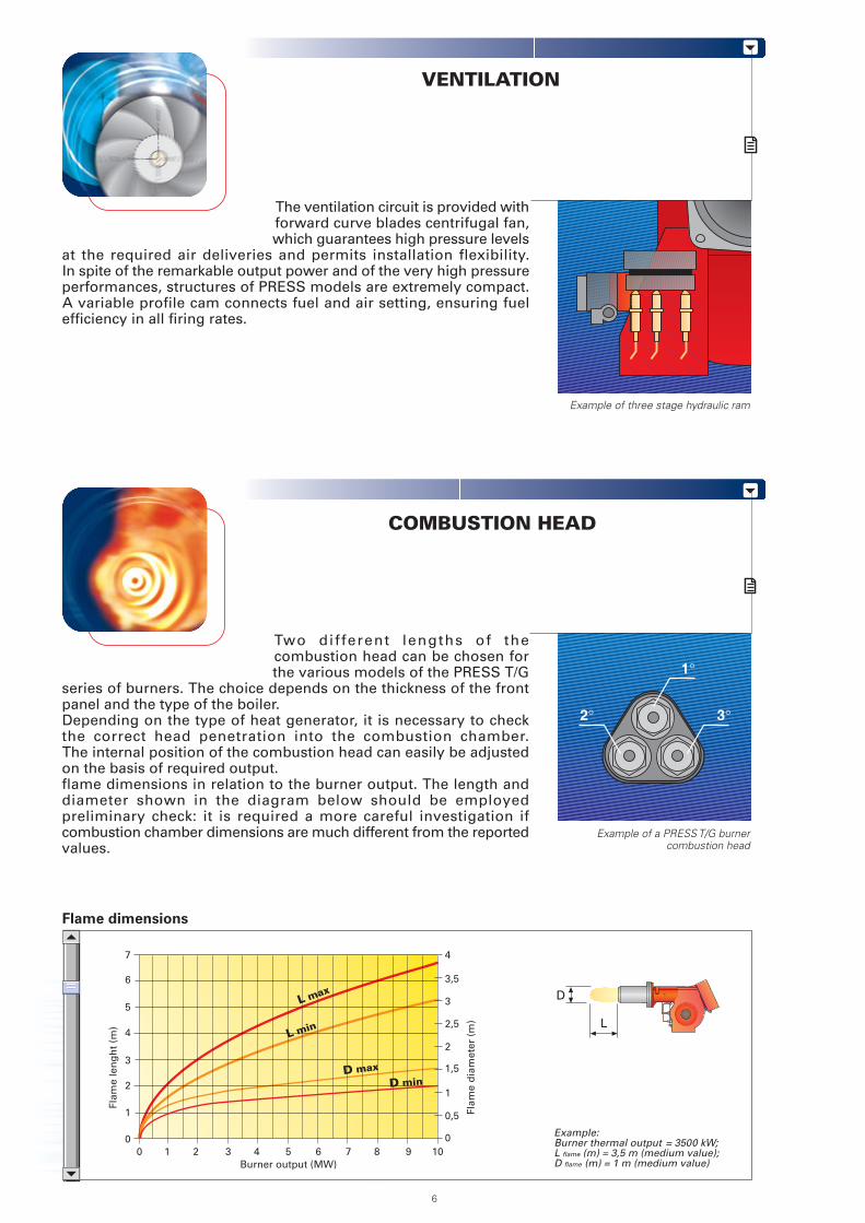
series of burners. The choice depends on the thickness of the frontpanel and the type of the boiler.Depending on the type of heat generator, it is necessary to checkthe correct head penetration into the combustion chamber.The internal position of the combustion head can easily be adjustedon the basis of required output.flame dimensions in relation to the burner output. The length anddiameter shown in the diagram below should be employedpreliminary check: it is required a more careful investigation ifcombustion chamber dimensions are much different from the reportedvalues.
The ventilation circuit is provided withforward curve blades centrifugal fan,which guarantees high pressure levels
at the required air deliveries and permits installation flexibility.In spite of the remarkable output power and of the very high pressureperformances, structures of PRESS models are extremely compact.A variable profile cam connects fuel and air setting, ensuring fuelefficiency in all firing rates.
COMBUSTION HEAD
VENTILATION
Example of three stage hydraulic ram
Flame dimensions
Example of a PRESS T/G burnercombustion head
D
L
1°
2° 3°
Example:Burner thermal output = 3500 kW;L flame (m) = 3,5 m (medium value);D flame (m) = 1 m (medium value)Burner output (MW)
0 2
3
5
1
1 3
2
4
6
7
4 5 6 7 8 9 10
Flam
e le
ng
ht
(m)
Flam
e d
iam
eter
(m
)
0
4
0
0,5
1
1,5
2
2,5
3
3,5
L max
L min
D max
D min
6
OPERATION
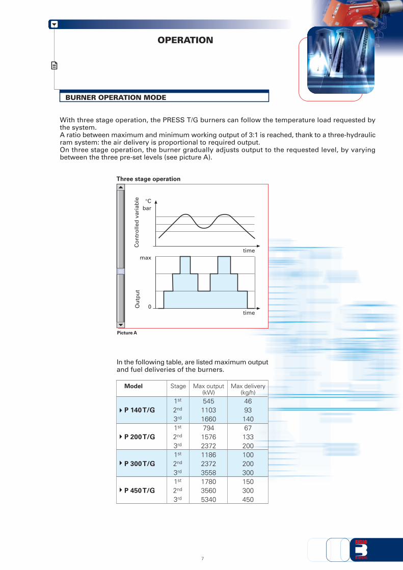
With three stage operation, the PRESS T/G burners can follow the temperature load requested bythe system.A ratio between maximum and minimum working output of 3:1 is reached, thank to a three-hydraulicram system: the air delivery is proportional to required output.On three stage operation, the burner gradually adjusts output to the requested level, by varyingbetween the three pre-set levels (see picture A).
BURNER OPERATION MODE
Ou
tpu
tC
on
tro
lled
var
iab
le
Picture A
Three stage operation
bar°C
time
time
max
0
In the following table, are listed maximum outputand fuel deliveries of the burners.
P 140 T/G
P 200 T/G
P 300 T/G
P 450 T/G
Max output(kW)
1st
2nd
3rd
1st
2nd
3rd
1st
2nd
3rd
1st
2nd
3rd
5451103166079415762372118623723558178035605340
Stage
469314067133200100200300150300450
Max delivery(kg/h)
Model
7

All PRESS T/G series burners are fitted with a new microprocessor control panel for the supervisionduring intermittent operation.For helping the commissioning and maintenance work, there are two main elements:
The lock-out reset button is the central operating element for resetting the burner controland for activating / deactivating the diagnostic functions.
The multi-color LED is the central indication element for visual diagnosis and interfacediagnosis.
Both elements are located under the transparent cover of lock-out reset button, as showed below.
There are two diagnostic choices, for indication of operation and diagnosis of fault cause:
- visual diagnosis :
- interface diagnosis : by the interface adapterand a PC with dedicateds o f t w a r e o r b y apredisposed flue gasanalyzer (see paragraphaccessories).
Switch
COMPUTER
or
FLUE GASANALYSER
INTERFACE ADAPTER
Switch
8
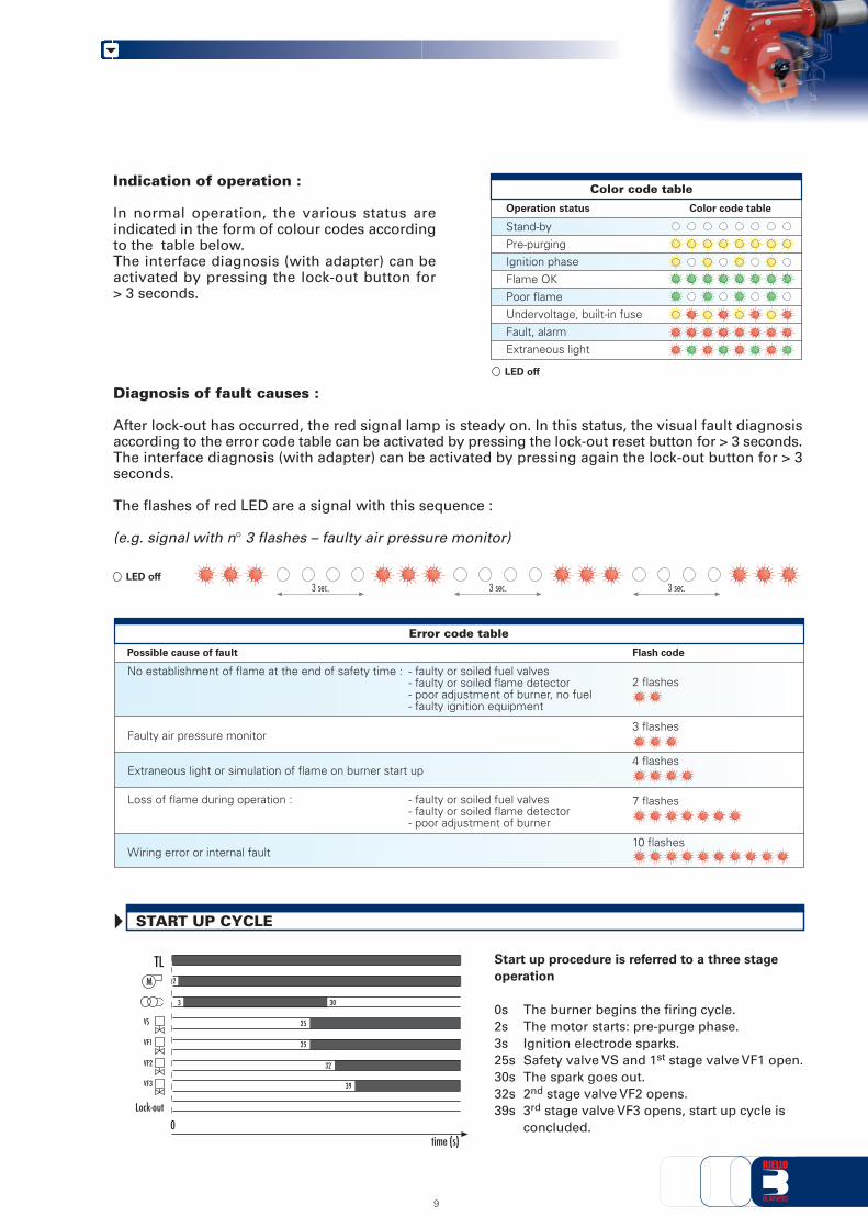
Start up procedure is referred to a three stage
operation
0s The burner begins the firing cycle.2s The motor starts: pre-purge phase.3s Ignition electrode sparks.25s Safety valve VS and 1st stage valve VF1 open.30s The spark goes out.32s 2nd stage valve VF2 opens.39s 3rd stage valve VF3 opens, start up cycle is
concluded.
Indication of operation :
In normal operation, the various status areindicated in the form of colour codes accordingto the table below.The interface diagnosis (with adapter) can beactivated by pressing the lock-out button for> 3 seconds.
Diagnosis of fault causes :
After lock-out has occurred, the red signal lamp is steady on. In this status, the visual fault diagnosisaccording to the error code table can be activated by pressing the lock-out reset button for > 3 seconds.The interface diagnosis (with adapter) can be activated by pressing again the lock-out button for > 3seconds.
The flashes of red LED are a signal with this sequence :
(e.g. signal with n° 3 flashes – faulty air pressure monitor)
Color code table
Operation status
Stand-byPre-purgingIgnition phaseFlame OKPoor flameUndervoltage, built-in fuseFault, alarmExtraneous light
Color code table
LED off
LED off3 sec. 3 sec. 3 sec.
Lock-out
TL
time (s)
M
VS
VF1
VF2
VF3
0
2
3
32
39
30
25
25
START UP CYCLE
9
Error code table
Possible cause of fault Flash code
No establishment of flame at the end of safety time : - faulty or soiled fuel valves- faulty or soiled flame detector- poor adjustment of burner, no fuel- faulty ignition equipment
Faulty air pressure monitor
Extraneous light or simulation of flame on burner start up
Loss of flame during operation : - faulty or soiled fuel valves- faulty or soiled flame detector- poor adjustment of burner
Wiring error or internal fault
2 flashes
3 flashes
4 flashes
7 flashes
10 flashes

“THREE STAGE” OPERATION
The following tableshows the supply leadsections and the type offuse to be used.
MB - Burner terminal boardTS - Safety thermostatS - External lock-out signalIN - Manual switchTL - Threshold thermostatMA - Star-delta starter terminal stripT2 - 2nd stage thermostatT3 - 3rd stage thermostatT6A - 6A fuseF - Fuse (see table A)L - Lead section (see table A)PS - Lock out reset button
MB - Burner terminal boardTS - Safety thermostatS - External lock-out signalIN - Manual switchTL - Threshold thermostatT2 - 2nd stage thermostatT3 - 3rd stage thermostatT6A - 6A fuseF - Fuse (see table A)L - Lead section (see table A)PS - Lock out reset button
Star delta start-up version P 300-450 T/G
Direct start-up version P 140-200-300 T/G
WIRING DIAGRAMS
Electrical connections must be madeby qualified and skilled personnel,according to the local norms.
Example of control panel forP 200 T/G models
P
P
P
L1 L2 L3 N LMB S3 T1 30 T2
F
L
PE L1 L2 L3
T6A
NL
TS S
N
N
P
T6 T8 T9 R3
~ 50Hz 230V
IN
~~ 50Hz 230V3
3N 50Hz 400/230V~M3
31
TL
T2
T3
PS
T11
~ 50Hz 230V3
U1V1 W1U2 LMB S3 T1 30 T2
FL
PE L1 L2 L3
T6A
TS
S
N
N
P
T6 T8 T9 T11 R3
1 2 3 4 35 36 3738 39 40 41 42 43 44 45 5 6
V2 W2 N ST1
V20
MA
E
IN
~3N 50Hz 400/230V
~M3
V21 S1 31
TLP
T2P
T2P PS
Table A
Direct Star delta
P 140 T/G
230V
T252,5
-
Model
(A)
(mm2)
(mm2)
FLE
400V
T252,5-
P 200 T/G
230V
T354-
400V
T252,5-
P 300 T/G
230V
T636-
400V
T504-
P 300 T/G
230V
T5064
400V
T354
2,5
P 450 T/G
230V
T63106
400V
T5064
10
0 123
P 200 T/G

EMISSIONS
The emission data has been measured in the various models at maximum output, according toEN 267 standard.
P 140 T/G P 200 T/G P 300 T/G P 450 T/G
mg
/kW
h
0
50
100
150
200
250NOx EMISSIONS
P 140 T/G P 200 T/G P 300 T/G P 450 T/G
mg
/kW
h
0
10
20
30
40
50
CO EMISSIONS
60
70
P 140 T/G P 200 T/G P 300 T/G P 450 T/G
NOISE EMISSIONS
dB
(A)
0
20
40
60
80
100
11

P 140 T/G
P 200 T/G
P 300 T/G
P 450 T/G
BURNER - BOILER MOUNTING FLANGE
BURNER
PACKAGING
L
L M
M
O
N
P 140 T/G
P 200 T/G
P 300 T/G
P 450 T/G
X - X (1)
Z
Y
OVERALL DIMENSIONS (mm)
M14M16M18M20
N ØM260260260310
230---
L225255300340
O
Model X - X (1) Y kg
1500150017801780
93093010851085
130220238300
Z
905905990990
Model
(1) Length with extended combustion head.
12
A
B
E F - F (1)
H
I
O - O (1)
Model A B I
P 140 T/G
P 200 T/G
P 300 T/G
P 450 T/G
365396447508
765796858950
467467496525
890890
10001070
F (1) H
222250295336
F
473501574606
E
363391444476
-----
O
1250128014401546
O (1)
1360139015701676
----
-
(1) Length with extended combustion head.

INSTALLATION DESCRIPTION
Installation, start-up and maintenance must be carried out byqualified and skilled personnel.All operations must be performed in accordance with thetechnical handbook supplied to the burner.
All the burners have slide bars, for easier installation and maintenance.
After removing the cover, the split pin and the pin, the nuts and the screws, dismantle the blasttube from the burner and fix it to the boiler.
Adjust the combustion head.
Refit the burner casing to the slide bars.
Install the nozzles, choosing it on the basis of the maximum boiler output and following thediagrams included in the burner instruction handbook.
Check the position of the electrodes.
Close the burner, fasten the screws, the nuts, the split pin and the pin.
The burners are supplied for connection to two pipes fuel supply system.
Connect the ends of the flexible pipes to the suction and return pipework using the suppliednipples.
Make the electrical connections to the burner following the wiring diagrams included in theinstruction handbook.
Prime the pump by turning the motor (after checking rotation direction).
On start up, check:- Pressure pump and valve unit regulator (to max. and min.)- Combustion quality, in terms of unburned substances and excess air.
BURNER SETTING
HYDRAULIC AND ELECTRICAL CONNECTIONS AND START-UP
13

BURNER ACCESSORIES
Nozzles
The nozzles are part of the standard equipment. The following table shows the features and codes onthe basis of the required output. For the choice of the three related nozzles, refer to the burner handbook.
Nozzle type 60° B
P 140 T/GP 140 T/GP 140 T/GP 140 T/G - P 200 T/GP 140 T/G - P 200 T/GP 140 T/G - P 200 T/GP 140 T/G - P 200 T/GP 140 T/G - P 200 T/GP 140 T/G - P 200 T/GP 140 T/G - P 200 T/GP 140 T/G - P 200 T/GP 140 T/G - P 200 T/GP 140 T/G - P 200 T/GP 140 T/G - P 200 T/GP 200 T/GP 200 T/GP 200 T/G - P 300 T/GP 200 T/G - P 300 T/GP 300 T/GP 300 T/GP 300 T/G - P 400 T/GP 300 T/G - P 400 T/GP 300 T/G - P 400 T/GP 300 T/G - P 400 T/GP 300 T/G - P 400 T/GP 450 T/GP 450 T/GP 450 T/GP 450 T/GP 450 T/G
Burner GPH Rated output (kg/h) Nozzle
at 10 bar at 12 bar at 14 bar code
3,50 13,5 14,8 16,1 3042162
4,00 15,4 17 18,4 3042172
4,50 17,3 19,1 20,7 3042182
5,00 19,2 21,2 23 3042192
5,50 21,1 23,3 25,3 3042202
6,00 23,1 25,5 27,7 3042212
6,50 25 27,6 30 3042222
7,00 26,9 29,7 32,3 3042232
7,50 28,8 31,8 34,6 3042242
8,00 30,8 33,9 36,9 3042252
8,50 32,7 36,1 39,2 3042262
9,50 36,5 40,3 43,8 3042282
10,00 38,4 42,4 46,1 3042292
11,00 42,3 46,7 50,7 3042312
12,00 46,1 50,9 55,3 3042322
13,00 50 55,1 59,9 3042332
14,00 53,8 59,4 64,5 3042352
15,00 57,7 63,6 69,2 3042362
16,00 61,5 67,9 73,8 3042382
17,00 65,4 72,1 78,4 3042392
18,00 69,2 76,4 83 3042412
19,00 73 80,6 87,6 3042422
20,00 76,9 84,8 92,2 3042442
22,00 84,6 93,3 101,4 3042462
24,00 92,2 101,8 110,6 3042472
26,00 99,9 110,3 119,9 3042482
28,00 107,6 118,8 129,1 3042492
30,00 110,4 122 132,4 3042502
32,00 117,8 130,1 150,1 3042512
35,00 128,8 142,1 154,5 3042522
14

PC interface kit
To connect the flame control panel to a personal computer for the transmission of operation, faultsignals and detailed service information, an interface adapter with PC software are available.
Spacer kit
If burner head penetration in the combustion chamber needs reducing, varying thickness spacers areavailable, as given in the following table.
P 140 T/GP 200 T/GP 300 T/GP 450 T/G
Burner Spacer code
3000722
3000722
3000723
3000751
Spacer kit
110110130130
Spacer thickness S (mm)
S
Sound proofing box
If noise emissions need reducing, sound proofing hoods are available, as given in the following table.
P 140 T/G - P 200 T/GP 300 T/G - P 450 T/G
Burner
Sound proofing box
C4/5C7
Box type
1010
Average noisereduction [dB(A)] (*)
Box code
3010404
3010376
Burner support
For easier maintenance, a mobile burner support has been designed, which means the burner canbe dismantled without the need of forklift trucks.
P 300 T/G - P 450 T/G
Burner Support code
3000731
Burner support
Kit codeBurner
PC interface kit
3002719P140-200-300-450 T/G
(*) according to EN 15036-1 standard
15

PRESS 140 T/G TC FS1 3/230-400/50 230/50-60
A specific index guides your choice of burner fromthe various models available in the PRESS series.Below there is a clear and detailed specificationdescription of the product.
Size 140 ... 450
Series : PRESS
SPECIFICATION
BASIC DESIGNATION
EXTENDED DESIGNATION
Emission : ... Class 1 EN267
AVAILABLE BURNER MODELS
Head : TC Standard headTL Extended head
Flame control system : FS1 Standard (1 stop every 24 h)FS2 Continuous working (1 stop every 72 h)
Electrical supply to the system :
Auxiliary voltage :230/50 230V/50Hz220/60 220V/60Hz110/50-60 110V/50-60Hz
DESIGNATION OF SERIES
Other models are available on request.
P 140 T/G TC 3/230-400/50 230/50P 140 T/G TL 3/230-400/50 230/50
P 200 T/G TC 3/230-400/50 230/50P 200 T/G TL 3/230-400/50 230/50
P 300 T/G TC 3/230-400/50 230/50P 300 T/G TL 3/230-400/50 230/50P 300 T/G TC 3/230/50 230/50
P 300 T/G TL 3/230/50 230/50P 300 T/G TC 3/400/50 230/50P 300 T/G TL 3/400/50 230/50
P 450 T/G TC 3/230/50 230/50P 450 T/G TL 3/230/50 230/50P 450 T/G TC 3/400/50 230/50P 450 T/G TL 3/400/50 230/50
Operation : T/G Three stageP/G Modulating
3/230/50 3/230V/50Hz3/400/50 3N/400V/50Hz3/230-400/50 3/230V/50Hz - 3N/400V/50Hz3/220-380/60 3/220/60Hz - 3N/380V/60Hz3/200/50-60 3/200V/50-60Hz
16

PRODUCT SPECIFICATION
Burner:Monoblock forced draught oil burner with three stage operation, fully automatic, made up of:- Air suction circuit lined with sound-proofing material- Fan with forward curved blades high performance pressure levels- Air dampers for air setting controlled by a three stage hydraulic ram- Starting motor at 2850 rpm, three-phase 400 V with neutral, 50 Hz- Combustion head, that can be set on the basis of the combustion output, fitted with:
- stainless steel end cone, resistant to corrosion and high temperatures- ignition electrodes- flame stability disk
- Gears pump for high pressure fuel supply, fitted with:- filter- pressure regulator- connections for installing a pressure gauge and vacuometer- internal by-pass for single pipe installation
- Valve unit with a oil safety valve and three oil delivery valves on the output circuit;- Photocell for flame detection- Microprocessor based flame control panel, with diagnostic function- Burner on/off switch- Flame inspection window- Slide bars for easier installation and maintenance- Protection filter against radio interference- IP 40 electric protection level.
Conforming to:- 89/336 (2004/108) EC directive (electromagnetic compatibility)- 73/23 (2006/95) EC directive (low voltage)- 92/42/EC directive (performance)- 98/37/EC directive (machinery)- EN 267 (liquid fuel burners).
Standard equipment:- 2 flexible pipes for connection to the oil supply network- 2 nipples for the connection to the pump- 4 wiring looms fittings for electrical connections- 4 screws for fixing the burner flange to the boiler- Instruction handbook for installation, use and maintenance- Spare parts catalogue- 2 slide bar extensions (for the extended head models of P 300 T/G and P 450 T/G)- 3 nozzles- Gasket for flange- Starter (*)- Diffuser disk (P 450 T/G).
(*) For versions with star-delta starting.
Available accessories to be ordered separately:- Nozzles- Spacer kit- Sound-proofing box- Burner support- PC interface kit.
17

18

19

RIELLO S.p.A. - Via Ing. Pilade Riello, 5 - 37045 Legnago (VR) ItalyTel. ++39.0442630111 - Fax ++39.044221980
Internet: http://www.rielloburners.com - E-mail: [email protected]
TS
0038
UK
03 -
1/2
008
Since the Company is constantly engaged in the production improvement, the aesthetic anddimensional features, the technical data, the equipment and the accessories can be changed.
This document contains confidential and proprietary information of RIELLO S.p.A.Unless authorised, this information shall not be divulged, nor duplicated in whole or in part.