Embed Size (px)
Citation preview

COMPDYN 2011 III ECCOMAS Thematic Conference on
Computational Methods in Structural Dynamics and Earthquake Engineering M. Papadrakakis, M. Fragiadakis, V. Plevris (eds.)
Corfu, Greece, 25–28 May 2011
ON THE SEISMIC BEHAVIOUR AND DESIGN OF LIQUID STORAGE
TANKS
Patricia Pappa1, Daniel Vasilikis
1, Polynikis Vazouras
2, and Spyros A. Karamanos
1
1 Department of Mechanical Engineering University of Thessaly, Volos, Greece
e-mail: {davasili, patrpap, skara}@mie.uth.gr
2 Department of Civil Engineering University of Thessaly, Volos, Greece
e-mail: [email protected]
Keywords: liquid storage tank, seismic design, sloshing, finite elements, shell buckling.
Abstract. The paper examines some special issues on the structural behaviour of upright-
cylindrical liquid storage tanks, which are widely used in industrial facilities and for water
storage. Two main design standards are considered: EN 1998-4, a relatively new standard,
and Appendix E of API 650, which has been through substantial amendments and revisions in
its new version (11th
edition, 2007). There are significant differences between the two specifi-
cations, which are due to the fact that there exist several controversial issues on this subject,
open to further research. These issues are (a) the number of modes necessary to estimate ac-
curately the convective seismic force due to the hydrodynamic behaviour of the liquid con-
tainment; (b) the appropriate combination of the impulsive and the convective component of
seismic force; (c) the uplifting behaviour of unanchored tanks, with emphasis on the base
plate behaviour and the increase of meridional compression; (d) the choice of an appropriate
reduction (behaviour) factor for calculating both the impulsive and the convective force; (e)
the calculation of hydrodynamic hoop stresses due to liquid hydrodynamic motion; (f) the de-
sign of tanks against buckling at the top due to liquid sloshing; (g) the importance of nonlin-
ear wave sloshing effects.
The present paper is aimed at addressing the above issues based mainly on numerical
simulations. To simulate the tank shell and its structural behaviour, general-purpose finite
element software ABAQUS is employed, whereas to examine hydrodynamic effects, an in-
house numerical technique is developed. Existing data from previous investigations are also
considered. The results are aimed at better understanding of liquid storage tank seismic be-
haviour, bridging the gap between the two major design standards (EN 1998-4 and API 650-
Appendix E), towards safer seismic design of industrial facilities.
Patricia Pappa, Daniel Vasilikis, Polynikis Vazouras, Spyros A. Karamanos
2
1 INTRODUCTION
The structural response of liquid storage tanks under strong seismic loading constitutes an important issue for safeguarding the structural integrity of industrial facilities, especially in refineries and power plants. Significant damages of tanks have been reported in earthquake events [1][2]. The dominant mode of tank failure is in the form of elephant‟s foot buckling at the tank base. Other types of earthquake damages include buckling of the top of the tank shell, base plate failure due to uplifting, roof damage due to excessive sloshing, or shell damage at nozzle areas due to non-flexible connections with piping. Current design practice is based on the application of the API 650 provisions [3], as described in Appendix E. This Appendix has been initially incorporated in the standard in the late 70‟s [4], and has been substantially re-vised in the 11th edition published in 2007 [3] to be in accordance with the provisions of ASCE 7-05 [5]. In addition, to this standard, the newly published EN 1998-4 standard [6] contains design provisions for the seismic design of liquid storage tanks.
In the following, several issues related to the seismic analysis of liquid storage tanks and the determination of seismic action are addressed and examined, using numerical simulations. It has been recognized that there exist some specific issues that require further investigation and improvement. In particular, the following issues are addressed in the present study:
The number of sloshing modes to be considered in convective action and their combination with impulsive action.
The effects of shell deformation on the seismic response. Calculations of hoop hydrodynamic stresses Uplifting of unanchored tanks Buckling at the top of the tank Behavior factor of liquid storage tank and elephant‟s foot buckling Nonlinear sloshing effects
The investigation of those issues is aimed at comparing – where possible – the API 650 and the EN 1998-4 provisions for the seismic design of liquid storage tanks, towards propos-ing possible improvements/amendments of the EN 1998-4 standard. For this purpose, three liquid storage tanks are considered and their seismic response is simulated numerically:
(a) A moderately-broad tank, referred to as Tank I, is primarily considered. This is a 27.4-meter-diameter tank with a total height of 16.5 meters. The tank is unanchored. The filling height of the tank H is equal to 15.7, which makes an aspect ratio of the tank H R equal to 1.145. The tank thickness varies from 6.4 mm at its top course to
17.7 mm at its bottom course, the bottom plate is 6 mm thick, and has a 8-mm-thick annular plate.
(b) The second tank considered, referred to as Tank II, is a tall tank of 18-meter-diameter tank with a total height of 20 meters. The filling height of the tank H is equal to 19, which makes an aspect ratio of the tank H R equal to 2.1. The tank thickness varies from 6 mm at its top course to 10 mm at its bottom course and it is anchored .
(c) The third tank, referred to as Tank III, is a very broad tank of 68-meter-diameter with a total height of 20 meters. The filling height of the tank H is equal to 19 resulting to an aspect ratio H R equal to 0.558. The tank thickness varies from 34 mm at its top course to 38.5 mm at its bottom course.
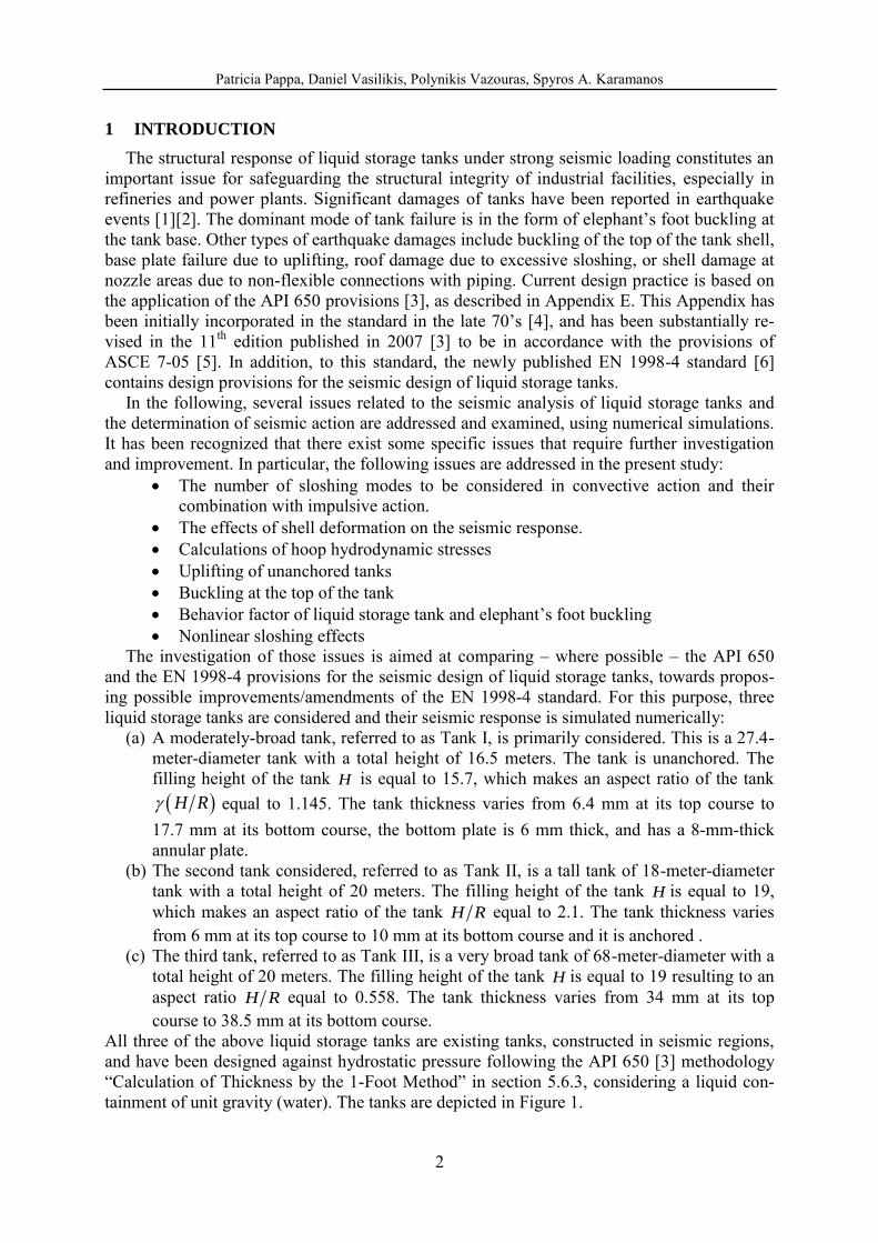
All three of the above liquid storage tanks are existing tanks, constructed in seismic regions, and have been designed against hydrostatic pressure following the API 650 [3] methodology “Calculation of Thickness by the 1-Foot Method” in section 5.6.3, considering a liquid con-tainment of unit gravity (water). The tanks are depicted in Figure 1.
Patricia Pappa, Daniel Vasilikis, Polynikis Vazouras, Spyros A. Karamanos
3
Figure 1: Tank I (left), tank II (center) and tank III (right) used for the parametric studies in the present paper.
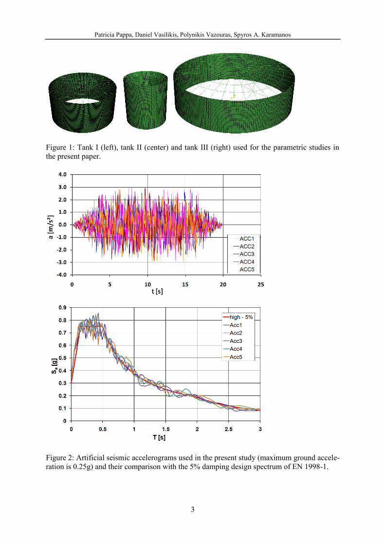
Figure 2: Artificial seismic accelerograms used in the present study (maximum ground accele-ration is 0.25g) and their comparison with the 5% damping design spectrum of EN 1998-1.
Patricia Pappa, Daniel Vasilikis, Polynikis Vazouras, Spyros A. Karamanos
4
2 SEISMIC DESIGN CODES FOR LIQUID STORAGE TANKS
Seismic design of liquid storage tanks in petrochemical facilities has been conducted with the relevant provisions of API 650. In particular, Appendix E of API 650 refers exclusively to seismic design, contains provisions for both determining seismic actions on tanks, as well as calculating the strength of the tank. The new edition of Appendix E includes provisions for site-specific seismic input, calculation of hoop hydrodynamic stresses, distinction between ringwall and slab overturning moments, freeboard requirements, and consideration of vertical excitation effects. The latter three issues are new, with respect to the old version of the Ap-pendix [4], whereas the issues of uplifting/anchorage and calculation of shell compression are significantly enhanced. It should be noted that seismic action calculations in the new version of Appendix E are in accordance with ASCE 7 standard [5].
European standard EN 1998-4 [6] is part of the CEN/TC250 standards, often referred to as “Structural Eurocodes”. It includes seismic provisions for silos, tanks and pipelines. In Chap-ter 2 some general provisions are stated. More specific rules for the seismic design of tanks are stated in Chapter 4 (e.g. behavior factor, limit state description), whereas extensive me-thodologies for calculating seismic action and verifying shell buckling are presented in Infor-mative Annex A. It has been recognized as a standard that contains state-of-the-art scientific information for determining seismic action, based on the work of Rammerstorfer et al. [7] and Scharf [8] as well as the work of Rotter [9] for shell buckling under internal pressure (ele-phant‟s foot). However, there are some issues that need further investigation and possible im-provement; a list of those issues is offered in section 1, and will be discussed extensively in the present paper.
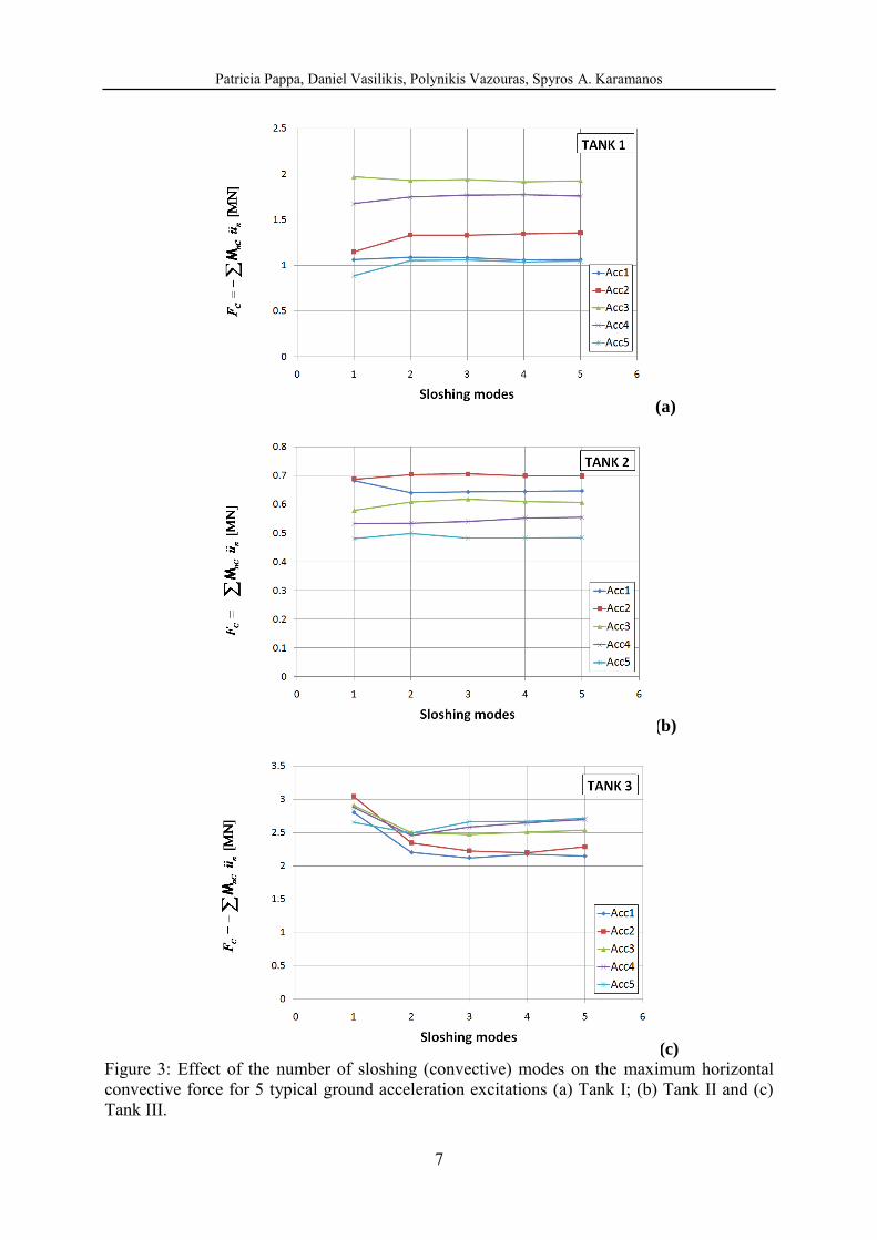
3 SLOSHING MODES AND THEIR COMBINATION WITH IMPUSIVE MOTION
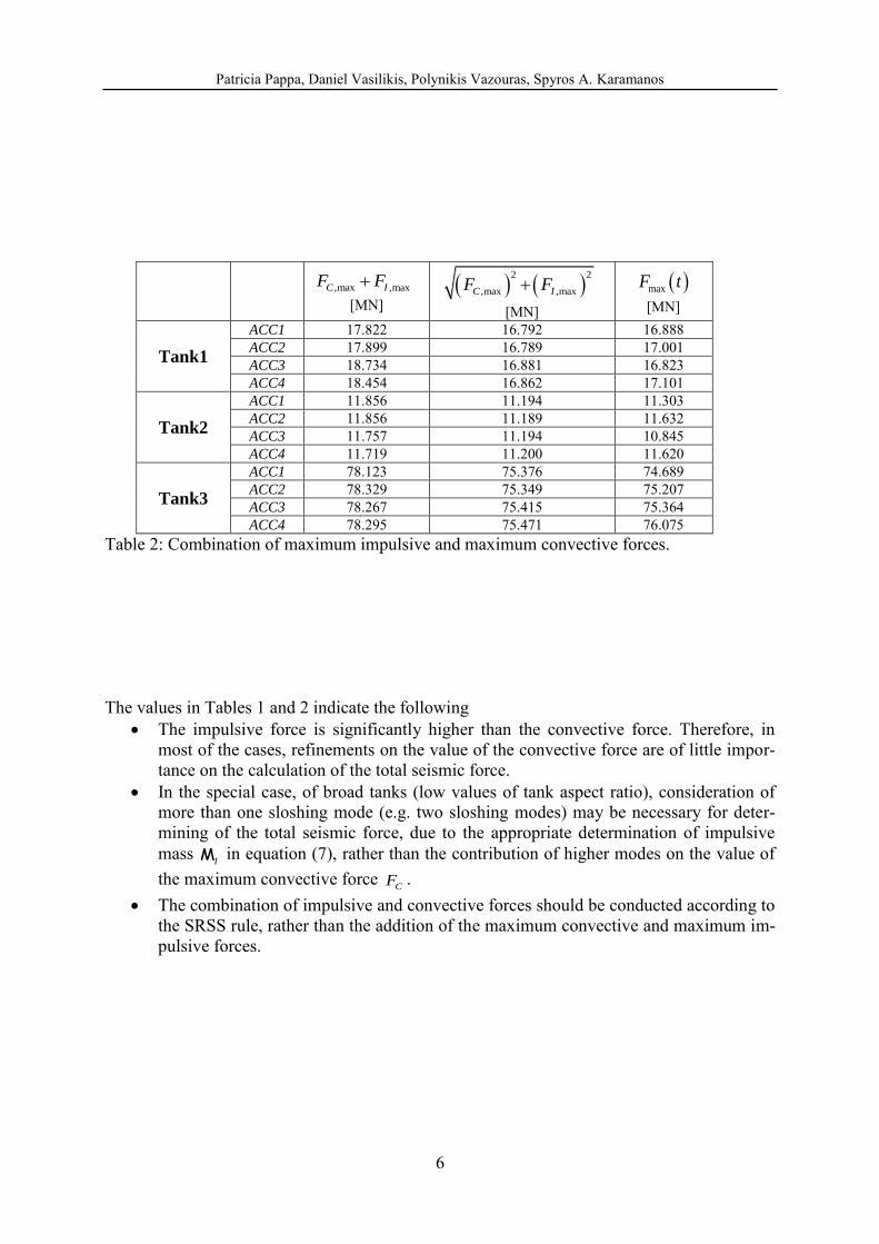
The first issue of interest concerns the number of sloshing (convective) modes to be consi-dered for determining the convective seismic force. The three tanks under consideration have been subjected to base-ground seismic acceleration from 10 artificial earthquakes, generated from the EN 1998-1 design spectrum, as shown in Figure 2. Tables 1 and 2 show some cha-racteristic results from 4 typical accelerograms from those earthquakes (denoted as ACC1, ACC2, ACC3 and ACC4 respectively), in terms of the maximum convective forces for sever-al modes, the corresponding maximum impulsive force, and the maximum total seismic force. For each earthquake event the maximum convective force was calculated as the product of the “convective” accelerations and the corresponding sloshing masses:
max
C nC n
n
F u
Μ (1)
where the “convective” acceleration is calculated from the following linear oscillator equation:
22 0n n n n n nu u X u X
(2) In the above equations, the convective (sloshing) mass is computed as follows
2 2
2 tanh
1
nnC
L n n
k R
k R k R
Μ
Μ
(3)
and
2
tanhnn n
Rk R k R
g
(4)
Patricia Pappa, Daniel Vasilikis, Polynikis Vazouras, Spyros A. Karamanos
5
is the sloshing (convective) circular frequency of the tank. Similarly, the maximum impulsive force was calculated as the product of the “impulsive” acceleration and the corresponding im-pulsive mass:
maxI IF X Μ
(5)
where the “impulsive” acceleration is calculated as follows
22 0I I I I I Iu u X u X
(6) In the above equation, the impulsive mass is computed as follows
1,2,3,...
I L nC
n
Μ Μ Μ
(7)
and
2
I
i
Et
C R
(8)
is the impulsive circular frequency of the tank. In the above expression iC is a nondimension-
al parameter that depends on the aspect ratio of the tank H R and where t is the average thickness of the tank shell. The integration of linear oscillator equations (2) and (6) is per-formed through a standard central-difference numerical method. In Tables 1, 2, and in Figure 3a, Figure 3b and Figure 3c, together with the maximum convective and impulsive forces, the maximum total forces are presented, for 4 typical artificial ground acceleration inputs (de-noted as ACC1, ACC2, ACC3 and ACC4 respectively), as computed by the following equa-tion
max
max
nC n I
n
F u X
Μ Μ
(9)
,maxIF [MN] ,maxCF [MN]
Tank1
ACC1 16.757 1.064 ACC2 16.749 1.149 ACC3 16.765 1.968 ACC4 16.778 1.675
Tank2
ACC1 11.173 0.682 ACC2 11.168 0.687 ACC3 11.178 0.578 ACC4 11.187 0.531
Tank3
ACC1 75.323 2.799 ACC2 75.287 3.042 ACC3 75.358 2.907 ACC4 75.416 2.878
Table 1: Maximum impulsive and maximum convective force for 4 typical artificial seismic inputs (0.25g).
Patricia Pappa, Daniel Vasilikis, Polynikis Vazouras, Spyros A. Karamanos
6
,max ,maxC IF F
[MN]
2 2
,max ,maxC IF F
[MN]
maxF t
[MN]
Tank1
ACC1 17.822 16.792 16.888 ACC2 17.899 16.789 17.001 ACC3 18.734 16.881 16.823 ACC4 18.454 16.862 17.101
Tank2
ACC1 11.856 11.194 11.303 ACC2 11.856 11.189 11.632 ACC3 11.757 11.194 10.845 ACC4 11.719 11.200 11.620
Tank3
ACC1 78.123 75.376 74.689 ACC2 78.329 75.349 75.207 ACC3 78.267 75.415 75.364 ACC4 78.295 75.471 76.075
Table 2: Combination of maximum impulsive and maximum convective forces. The values in Tables 1 and 2 indicate the following
The impulsive force is significantly higher than the convective force. Therefore, in most of the cases, refinements on the value of the convective force are of little impor-tance on the calculation of the total seismic force.
In the special case, of broad tanks (low values of tank aspect ratio), consideration of more than one sloshing mode (e.g. two sloshing modes) may be necessary for deter-mining of the total seismic force, due to the appropriate determination of impulsive mass
IΜ in equation (7), rather than the contribution of higher modes on the value of the maximum convective force
CF . The combination of impulsive and convective forces should be conducted according to
the SRSS rule, rather than the addition of the maximum convective and maximum im-pulsive forces.
Patricia Pappa, Daniel Vasilikis, Polynikis Vazouras, Spyros A. Karamanos
7
(a)
(b)
(c)
Figure 3: Effect of the number of sloshing (convective) modes on the maximum horizontal convective force for 5 typical ground acceleration excitations (a) Tank I; (b) Tank II and (c) Tank III.
Patricia Pappa, Daniel Vasilikis, Polynikis Vazouras, Spyros A. Karamanos
8
4 EFFECTS OF TANK DEFORMABILITY
In the case of rigid (non-deformable) liquid containers, the impulsive motion is exactly the same as the ground motion, whereas the convective motion is determined by the solution of the hydrodynamic problem within the rigid container. However, steel tanks are not rigid, they deform due to their small thickness with respect to their diameter.
A finite element analysis, which accounted for the dynamic interaction between the liquid and the deformable tank, has been reported by Scharf [8]. Scharf‟s analysis it is assumed that in flexible tanks the motion of the tank-liquid system is expressed as the sum of three contri-butions, referred to as: „rigid impulsive‟, „sloshing‟ and „flexible‟. The third component of liquid motion satisfies the condition that the radial velocity of the fluid along the wall equals the deformation velocity of the tank wall, as well as the conditions of zero vertical velocity at the tank bottom and zero pressure at the free surface of the fluid. The total seismic force is given by the following expression
I I nC n f f
n
F u u a Μ Μ Μ
(10)
In the above expression, the deformation mass fΜ is multiplied by the generalized coordinate
fa , which expresses the acceleration of the container relative to its base:
22f f f f f fa a a X (11)
where
f is the natural frequency of the deformation motion. Due to the fact that the dynam-ic coupling between the sloshing and the flexible components is very weak, due to the large differences between the frequencies of the sloshing motion and of the deformation of the wall, which allows determining the third component of the motion (the deformation component) independently of the others. The rigid impulsive and the sloshing components for non-deformable tanks remains therefore unaffected [10]-[12]. In the work of Scharf [8], closed-form expressions for the impulsive frequency and the deformation mass are reported, and those expressions are included in section A.3.1 of the Informative Annex A of EN 1998-4, stated below:
1/3
22
2 (0.157 1.49)f
E t H
R
(12)
where 1/3t is the thickness of the tank shell at height equal to 3H , and
0
1n
f
n
nL n
d
Μ
Μ (13)
where 1
0 1
1
( )cos( )( )
2( )
n
nn
n n
f dI
dI
(14)
2 1 2n n , and is a dimensionless parameter that depends on the shape function ( )f and is given by an awkward expression in EN 1998-4, paragraph A.3.1. Scharf [8] de-
Patricia Pappa, Daniel Vasilikis, Polynikis Vazouras, Spyros A. Karamanos
9
scribes a tedious iterative methodology that results in the determination of shape function ( )f . In lieu of such a rigorous and tedious analysis described above, simplified models have al-
so been developed to account for the interaction between the deformable cylindrical tank and the liquid. Such a model has been reported by Veletsos et al. [10], which constitutes the basis of the API 650 provisions [3] in calculating the impulsive seismic force. Similar to Scharf‟s
formulation [8], the Veletsos‟ model [10] further assumes that the convective motion of the liquid remains unaffected by tank shell deformation. Therefore, the hydrodynamic solution for the rigid container is still applicable, and the tank shell deformation affects only the impulsive motion. This methodology has been adopted by the API 650 provisions, whereas the simpli-fied methodology for deformable containers in section A.3.2.2 of EN 1998-4 is in-line with this approach. In particular, the latter provisions specify an impulsive frequency according to the equation (8), and the maximum seismic force is given by the following equation:
I I nC n
n
F u u Μ Μ
(15)
where the impulsive mass, the convective masses and the generalized coordinates
Iu and nu
are given by equations (2) and (6) respectively. Assuming the same damping ratio for the im-pulsive and the deformation motion (
f I ), one readily concludes that the two expressions (10) and (15) for the total seismic force provide identical results provided that (a) the two nat-ural frequencies
f and I are equal and (b) the corresponding masses
fΜ and IΜ are equal.
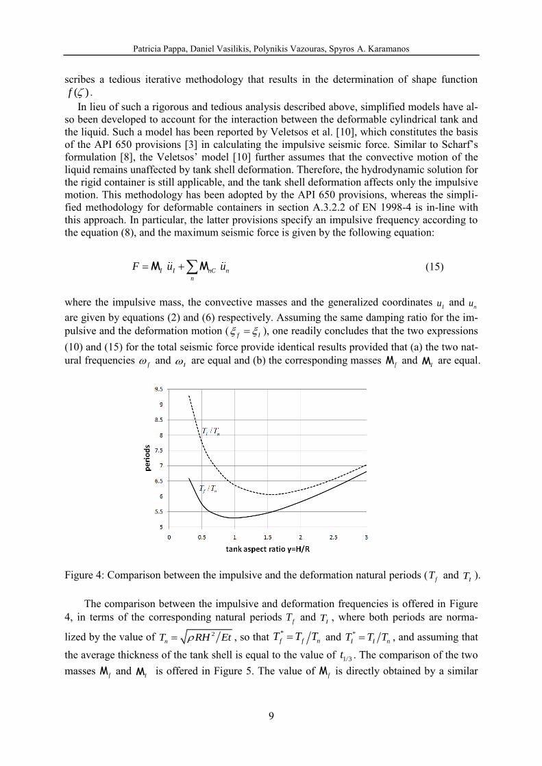
Figure 4: Comparison between the impulsive and the deformation natural periods (fT and
IT ).
The comparison between the impulsive and deformation frequencies is offered in Figure 4, in terms of the corresponding natural periods
fT and IT , where both periods are norma-
lized by the value of 2
nT RH Et , so that *
f f nT T T and *
I I nT T T , and assuming that the average thickness of the tank shell is equal to the value of 1/3t . The comparison of the two masses fΜ and
IΜ is offered in Figure 5. The value of fΜ is directly obtained by a similar
Patricia Pappa, Daniel Vasilikis, Polynikis Vazouras, Spyros A. Karamanos
10
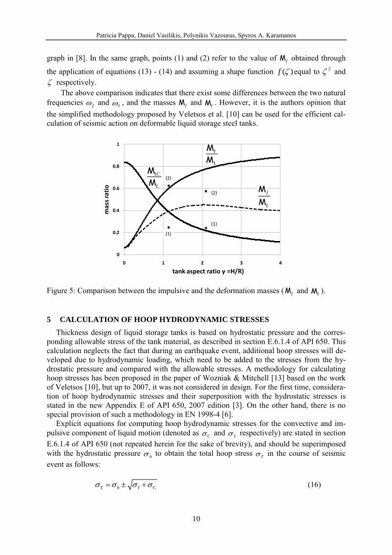
graph in [8]. In the same graph, points (1) and (2) refer to the value of fΜ obtained through
the application of equations (13) - (14) and assuming a shape function ( )f equal to 2 and respectively.
The above comparison indicates that there exist some differences between the two natural frequencies
f and I , and the masses
fΜ and IΜ . However, it is the authors opinion that
the simplified methodology proposed by Veletsos et al. [10] can be used for the efficient cal-culation of seismic action on deformable liquid storage steel tanks.
Figure 5: Comparison between the impulsive and the deformation masses (fΜ and
IΜ ).
5 CALCULATION OF HOOP HYDRODYNAMIC STRESSES
Thickness design of liquid storage tanks is based on hydrostatic pressure and the corres-ponding allowable stress of the tank material, as described in section E.6.1.4 of API 650. This calculation neglects the fact that during an earthquake event, additional hoop stresses will de-veloped due to hydrodynamic loading, which need to be added to the stresses from the hy-drostatic pressure and compared with the allowable stresses. A methodology for calculating hoop stresses has been proposed in the paper of Wozniak & Mitchell [13] based on the work of Veletsos [10], but up to 2007, it was not considered in design. For the first time, considera-tion of hoop hydrodynamic stresses and their superposition with the hydrostatic stresses is stated in the new Appendix E of API 650, 2007 edition [3]. On the other hand, there is no special provision of such a methodology in EN 1998-4 [6].
Explicit equations for computing hoop hydrodynamic stresses for the convective and im-pulsive component of liquid motion (denoted as
C and I respectively) are stated in section
E.6.1.4 of API 650 (not repeated herein for the sake of brevity), and should be superimposed with the hydrostatic pressure
h to obtain the total hoop stress T in the course of seismic
event as follows: T h I C (16)
0
0.2
0.4
0.6
0.8
1
0 1 2 3 4
mas
s ra
tio
tank aspect ratio γ =H/R)
f
L
Μ
Μ
I
L
Μ
Μ
1C
L
Μ
Μ
(1)
(1)
(2)
(2)
Patricia Pappa, Daniel Vasilikis, Polynikis Vazouras, Spyros A. Karamanos
11
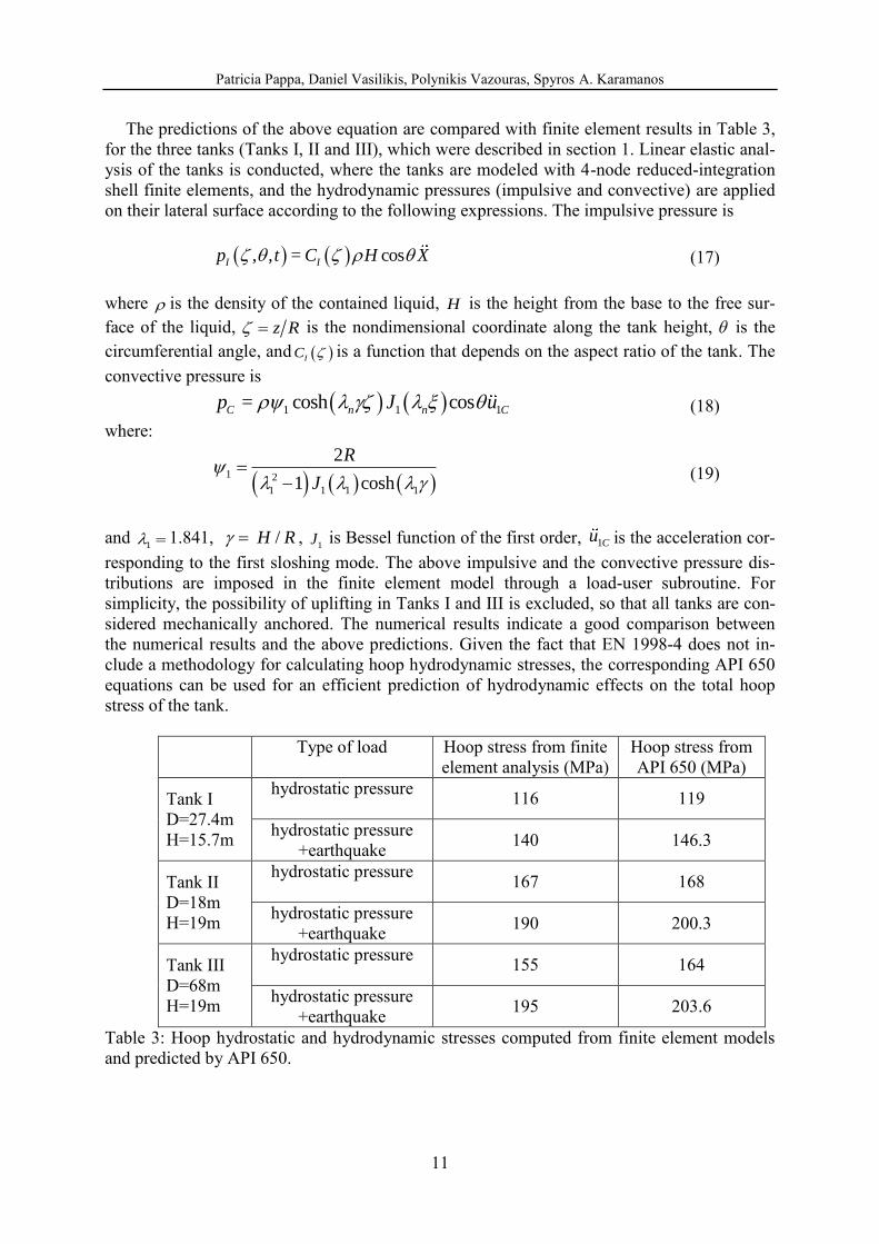
The predictions of the above equation are compared with finite element results in Table 3, for the three tanks (Tanks I, II and III), which were described in section 1. Linear elastic anal-ysis of the tanks is conducted, where the tanks are modeled with 4-node reduced-integration shell finite elements, and the hydrodynamic pressures (impulsive and convective) are applied on their lateral surface according to the following expressions. The impulsive pressure is
, , = cosI Ip t C H X (17)
where is the density of the contained liquid, H is the height from the base to the free sur-face of the liquid, z R is the nondimensional coordinate along the tank height, is the circumferential angle, and IC is a function that depends on the aspect ratio of the tank. The convective pressure is
1 1 1= cosh cosC n n Cp J u (18) where:
1 2
1 1 1 1
2
1 cosh
R
J
(19)
and
1 1.841, / H R , 1J is Bessel function of the first order, 1Cu is the acceleration cor-
responding to the first sloshing mode. The above impulsive and the convective pressure dis-tributions are imposed in the finite element model through a load-user subroutine. For simplicity, the possibility of uplifting in Tanks I and III is excluded, so that all tanks are con-sidered mechanically anchored. The numerical results indicate a good comparison between the numerical results and the above predictions. Given the fact that EN 1998-4 does not in-clude a methodology for calculating hoop hydrodynamic stresses, the corresponding API 650 equations can be used for an efficient prediction of hydrodynamic effects on the total hoop stress of the tank.
Type of load Hoop stress from finite element analysis (MPa)
Hoop stress from API 650 (MPa)
Tank I D=27.4m H=15.7m
hydrostatic pressure 116 119
hydrostatic pressure +earthquake 140 146.3
Tank II D=18m H=19m
hydrostatic pressure 167 168
hydrostatic pressure +earthquake 190 200.3
Tank III D=68m H=19m
hydrostatic pressure 155 164
hydrostatic pressure +earthquake 195 203.6
Table 3: Hoop hydrostatic and hydrodynamic stresses computed from finite element models and predicted by API 650.
Patricia Pappa, Daniel Vasilikis, Polynikis Vazouras, Spyros A. Karamanos
12
6 UPLIFTING EFFECTS ON UNANCHORED TANKS
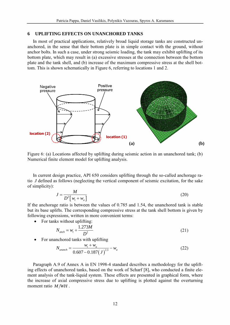
In most of practical applications, relatively broad liquid storage tanks are constructed un-anchored, in the sense that their bottom plate is in simple contact with the ground, without anchor bolts. In such a case, under strong seismic loading, the tank may exhibit uplifting of its bottom plate, which may result in (a) excessive stresses at the connection between the bottom plate and the tank shell, and (b) increase of the maximum compressive stress at the shell bot-tom. This is shown schematically in Figure 6, referring to locations 1 and 2.
(a) (b)
Figure 6: (a) Locations affected by uplifting during seismic action in an unanchored tank; (b) Numerical finite element model for uplifting analysis.
In current design practice, API 650 considers uplifting through the so-called anchorage ra-tio J defined as follows (neglecting the vertical component of seismic excitation, for the sake of simplicity):
2
t a
MJ
D w w
(20)
If the anchorage ratio is between the values of 0.785 and 1.54, the unanchored tank is stable but its base uplifts. The corresponding compressive stress at the tank shell bottom is given by following expressions, written in more convenient terms:
For tanks without uplifting:
2
1.273anch t
MN w
D
(21)
For unanchored tanks with uplifting
2.3
0.607 0.187
t aunanch a
w wN w
J
(22)
Paragraph A.9 of Annex A in EN 1998-4 standard describes a methodology for the uplift-
ing effects of unanchored tanks, based on the work of Scharf [8], who conducted a finite ele-ment analysis of the tank-liquid system. These effects are presented in graphical form, where the increase of axial compressive stress due to uplifting is plotted against the overturning moment ratio M WH .
location (1)location (2)
Patricia Pappa, Daniel Vasilikis, Polynikis Vazouras, Spyros A. Karamanos
13
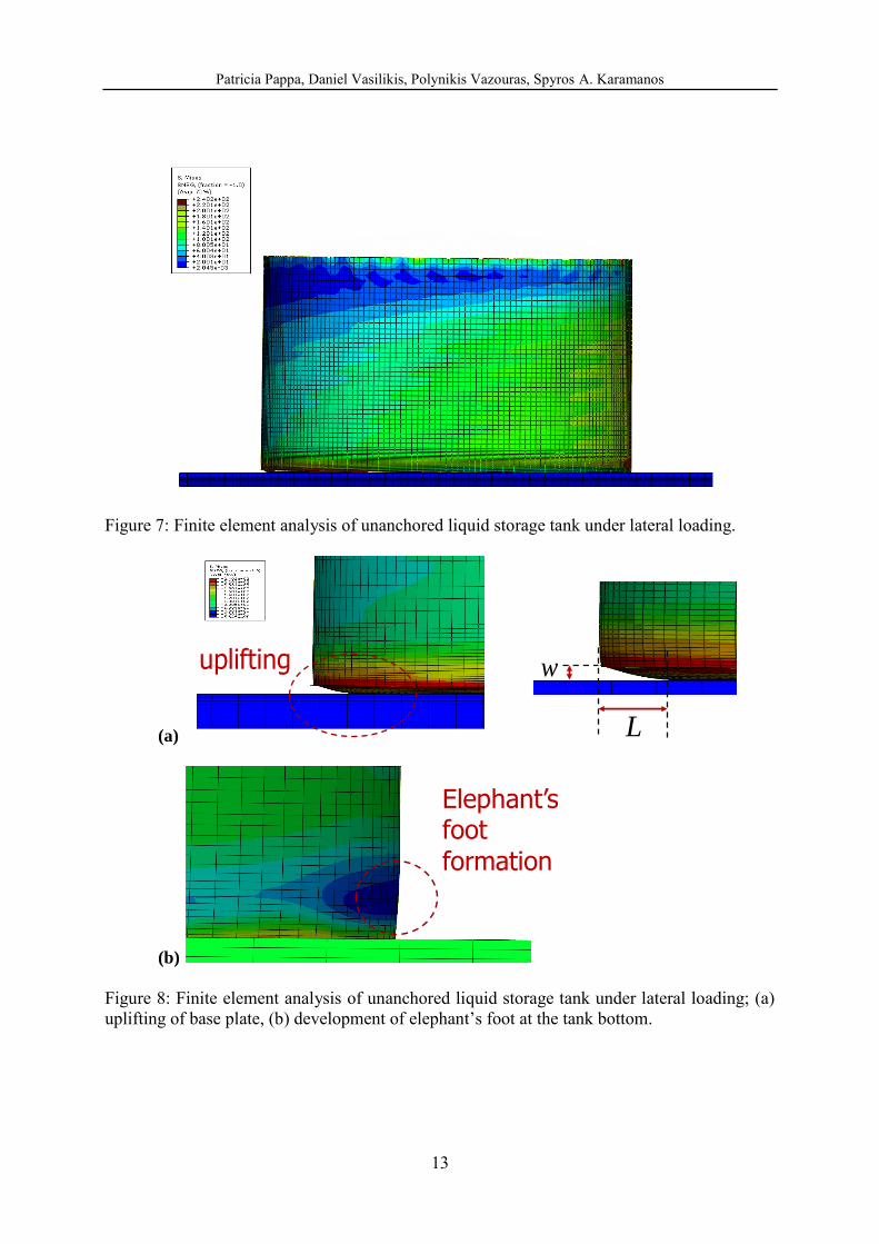
Figure 7: Finite element analysis of unanchored liquid storage tank under lateral loading.
(a)
(b) Figure 8: Finite element analysis of unanchored liquid storage tank under lateral loading; (a) uplifting of base plate, (b) development of elephant‟s foot at the tank bottom.
uplifting
L
w
Elephant’s foot formation

Patricia Pappa, Daniel Vasilikis, Polynikis Vazouras, Spyros A. Karamanos
14
Figure 9: Overturning moment M versus top horizontal displacement U of tank, subjected to finite element pushover analysis.
Figure 10: Increase of axial compressive stress on tank shell wall due to uplifting with respect to the overturning moment; finite element pushover analysis versus EN 1998-4 provisions.
Nu
nan
ch/N
anch
FE results
γ=1γ=2

Patricia Pappa, Daniel Vasilikis, Polynikis Vazouras, Spyros A. Karamanos
15
Figure 11: Uplifting size w in terms of overturning moment for Tank I; finite element pushov-er analysis.
Figure 12: Uplifting length L in terms of uplifting size w for Tank I; finite element pushover analysis.
FE results
γ=1γ=2
FE results
γ=1
γ=2

Patricia Pappa, Daniel Vasilikis, Polynikis Vazouras, Spyros A. Karamanos
16
Figure 13: Increase of axial compressive stress on tank shell wall due to uplifting with respect to the overturning moment at the tank shell bottom; finite element pushover analysis versus API 650 provisions.
Herein, using more rigorous finite element simulation tools, the above API 650 and EN 1998-4 provisions for tank uplifting are evaluated. Special emphasis is given on effects of up-lifting the compressive stress that causes elephant‟s foot buckling, which constitutes the major failure mode of the tank under strong earthquake loading. For this purpose, Tank I ( 1.145H R ) was simulated with shell finite elements, with the model shown in Figure 6b. All parts of the interacting system were modeled: the tank shell, the truss roof, the base plate, the annular plate, and the ground. Four-node reduced-integration shell elements are employed to model the tank shell and the base/annular plates, the truss roof is modeled with beam ele-ments, whereas solid elements are employed for modeling the ground. Contact conditions are considered between the base/annular plate and the ground, with friction coefficient equal to 0.3, allowing for tank uplift. The analysis is nonlinear static, and the hydrodynamic pressure is applied on the tank shell and the base plate for both the impulsive and the convective com-ponent. Considering this distribution of pressure, nonlinear “pushover” analysis is conducted controlling the value of the pressure multiplier, through a Riks continuation algorithm, which allows for the detection of possible instability (buckling) phenomena at the tank shell. Figure 7 and Figure 8 show the uplifting response of Tank I, as obtained by the present finite element simulation.
Figure 9 shows the horizontal displacement of the top of the tank in terms of the norma-lized overturning moment at the tank base M WH . The value of M is obtained by an appro-priate integration of the pressure on the tank shell surface. The increase of axial compressive stress due to uplift is shown in Figure 10 and the numerical results are compared with the graphs in EN 1998-4. The comparison shows that the EN 1998-4 curves are quite conserva-tive in predicting the increase of axial stress due to uplift. In Figure 11 and Figure 12, the up-lift magnitude and as the uplift length are plotted. Comparing the numerical results in Figure 9 and in Figure 11, one readily observes nonlinear inelastic behavior of the tank, as soon as some uplifting of the tank starts. This is associated with inelastic deformation at the uplifted
FE results
API 650N
un
anch
/Nan
ch
J=0.785J=1.54
Patricia Pappa, Daniel Vasilikis, Polynikis Vazouras, Spyros A. Karamanos
17
area of the base plate. Furthermore, the comparison between the numerical results and the curves of EN 1998-4 shows that the EN 1998-4 curves represent the general trend but are quite conservative in predicting the effect of uplifting on the axial compressive stress.
Finally, in Figure 13, the finite element results for the axial compressive stress increase due to uplifting are compared with the corresponding provisions of API 650, i.e. expressions (21) and (22). The comparison shows that the API 650 provisions are very conservative. However, this comparison is somewhat unfair, because the overturning moment in API 650 is calculated considering a large value of reduction factor. The value of the reduction factor is discussed in a subsequent section.
7 ELEPHANT’S FOOT BUCKLING
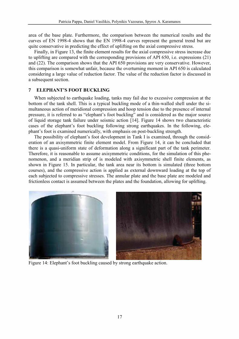
When subjected to earthquake loading, tanks may fail due to excessive compression at the bottom of the tank shell. This is a typical buckling mode of a thin-walled shell under the si-multaneous action of meridional compression and hoop tension due to the presence of internal pressure, it is referred to as “elephant‟s foot buckling” and is considered as the major source of liquid storage tank failure under seismic action [14]. Figure 14 shows two characteristic cases of the elephant‟s foot buckling following strong earthquakes. In the following, ele-phant‟s foot is examined numerically, with emphasis on post-buckling strength.
The possibility of elephant‟s foot development in Tank I is examined, through the consid-eration of an axisymmetric finite element model. From Figure 14, it can be concluded that there is a quasi-uniform state of deformation along a significant part of the tank perimeter. Therefore, it is reasonable to assume axisymmetric conditions, for the simulation of this phe-nomenon, and a meridian strip of is modeled with axisymmetric shell finite elements, as shown in Figure 15. In particular, the tank area near its bottom is simulated (three bottom courses), and the compressive action is applied as external downward loading at the top of each subjected to compressive stresses. The annular plate and the base plate are modeled and frictionless contact is assumed between the plates and the foundation, allowing for uplifting.
Figure 14: Elephant‟s foot buckling caused by strong earthquake action.

Patricia Pappa, Daniel Vasilikis, Polynikis Vazouras, Spyros A. Karamanos
18
Figure 15: Development of elephant‟s foot, as predicted by the finite element analysis.
The results from the finite element analysis are shown in Figure 16, in terms of the equili-brium path of the applied axial stress on the tank wall in terms of the vertical and the horizon-tal outwards displacement of the tank wall. The most important observation refers to the fact that the The buckling shape obtained from the finite element analysis is shown in Figure 17 (in a three-dimensional form) and is very similar to observations from real earthquake events, as shown in Figure 14b. The most important observation refers to post-buckling response of the tank, which appears to be unstable; after reaching a maximum stress (load) the capacity drops very rapidly, indicating that the tank has not any ability of absorbing significant amounts of inelastic energy.
8 BUCKLING AT THE TOP OF THE TANK
Apart from elephant‟s foot buckling at the tank bottom, previous experience has indicated
that liquid storage tanks suffer from buckling at their top. This is called “sloshing buckling”
and it is shown in Figure 18. The first attempt to explain this phenomenon was report in the paper by Natsiavas and Babcock [15]. In that work, this type of buckling was attributed to the alternating sign of hydrodynamic (sloshing) pressure on the tank wall during the seismic exci-tation. More specifically, the tank under hydrostatic pressure exhibits tensile stresses on the tank shell that prevent buckling. However, when – in the course of a seismic event – this pres-sure becomes negative, i.e. directed inwards, it may overtake the internal (outward) hydrostat-ic pressure, so that the thin-walled tank top is locally under external pressure leading to shell buckling. It is important to note that, at the top of the tank, hydrostatic pressure is small, so that this overtaking is quite likely to occur, depending on the magnitude of the seismic action.
(a) (b) (c)
elephant’s foot buckling
Tank shell
Bottom plate0
0.05
0.1
0.15
0.2
0.25
0.3
0.35
0 0.01 0.02 0.03 0.04 0.05normalized horizontal displacement (δ/R)
no
rmalized
heig
ht
δ/L=0.00052
δ/L=0.00126
δ/L=0.0063
D=27.4 m
H=16.514 m
Hliq=15.7 m

Patricia Pappa, Daniel Vasilikis, Polynikis Vazouras, Spyros A. Karamanos
19
Figure 16: Compressive stress developed at the tank shell wall versus: (a) horizontal outward displacement of the wall, (b) vertical displacement at the top of the model.
Figure 17: Elephant‟s foot buckling, as obtained by the finite element simulation.
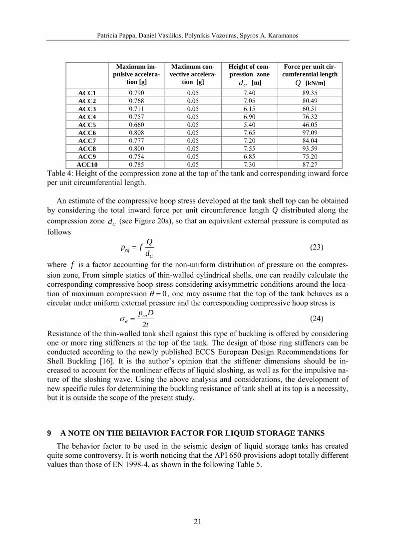
To quantify this effect, Tank I is considered and the impulsive and convective pressures are computed at 0 and for 7 artificial earthquakes, corresponding to a maximum ground acceleration of 0.25g. Figure 19 shows the distribution of hydrostatic and hydrody-namic (maximum convective and maximum impulsive) pressure on the tank wall, at 0 , for a typical earthquake. Considering that the hydrodynamic pressure are of alternating sign, the numerical results in this graph indicate that outward hydrodynamic pressures may become dominant at the top part of the tank, resulting in an external pressurization of the tank at those locations, leading to buckling. This is shown more precisely in Figure 20, where the hydrody-namic pressures are subtracted from the hydrostatic pressure. The graphs indicate that the ex-ternal pressure of the tank shell extends over a significant part of its height
Cd as shown in Table 4 for 10 earthquake inputs, corresponding to 0.25g.
0
10
20
30
40
50
60
70
80
0 0.002 0.004 0.006 0.008 0.01 0.012
normalized horizontal displacement (δ/R)
Str
ess [
MP
a]
D=27.4 m
H=16.514 m
0
10
20
30
40
50
60
70
80
0 0.001 0.002 0.003 0.004 0.005 0.006 0.007
normalized vertical displacement (δ/L)
Str
ess [
MP
a]
D=27.4 m
H=16.514 m

Patricia Pappa, Daniel Vasilikis, Polynikis Vazouras, Spyros A. Karamanos
20
Figure 18: Sloshing buckling at the top of a tank; Kocaeli, Turkey earthquake 1999 [1].
Figure 19: Distribution of hydrostatic pressure and maximum hydrodynamic pressures (im-pulsive and convective) along the height of Tank I for a characteristic seismic event of 0.25g.
Figure 20: (a) Schematic representation of compressive (inward) pressures at the top of the tank; (b) Results from 10 artificial ground acceleration inputs (0.25g).
( )
C
H
z
Q p z dz z
z=H
Cz z
Cd
outward direction of the tank
,max ,max( ) HS C Ip z p p p
compression zone
Patricia Pappa, Daniel Vasilikis, Polynikis Vazouras, Spyros A. Karamanos
21
Maximum im-
pulsive accelera-
tion [g]
Maximum con-
vective accelera-
tion [g]
Height of com-
pression zone
Cd [m]
Force per unit cir-
cumferential length
Q [kN/m]
ACC1 0.790 0.05 7.40 89.35 ACC2 0.768 0.05 7.05 80.49 ACC3 0.711 0.05 6.15 60.51 ACC4 0.757 0.05 6.90 76.32 ACC5 0.660 0.05 5.40 46.05 ACC6 0.808 0.05 7.65 97.09 ACC7 0.777 0.05 7.20 84.04 ACC8 0.800 0.05 7.55 93.59 ACC9 0.754 0.05 6.85 75.20
ACC10 0.785 0.05 7.30 87.27 Table 4: Height of the compression zone at the top of the tank and corresponding inward force per unit circumferential length.
An estimate of the compressive hoop stress developed at the tank shell top can be obtained by considering the total inward force per unit circumference length Q distributed along the compression zone
Cd (see Figure 20a), so that an equivalent external pressure is computed as follows
eq
C
Qp f
d (23)
where f is a factor accounting for the non-uniform distribution of pressure on the compres-sion zone, From simple statics of thin-walled cylindrical shells, one can readily calculate the corresponding compressive hoop stress considering axisymmetric conditions around the loca-tion of maximum compression 0 , one may assume that the top of the tank behaves as a circular under uniform external pressure and the corresponding compressive hoop stress is
2
eqp D
t (24)
Resistance of the thin-walled tank shell against this type of buckling is offered by considering one or more ring stiffeners at the top of the tank. The design of those ring stiffeners can be conducted according to the newly published ECCS European Design Recommendations for Shell Buckling [16]. It is the author‟s opinion that the stiffener dimensions should be in-creased to account for the nonlinear effects of liquid sloshing, as well as for the impulsive na-ture of the sloshing wave. Using the above analysis and considerations, the development of new specific rules for determining the buckling resistance of tank shell at its top is a necessity, but it is outside the scope of the present study.
9 A NOTE ON THE BEHAVIOR FACTOR FOR LIQUID STORAGE TANKS
The behavior factor to be used in the seismic design of liquid storage tanks has created quite some controversy. It is worth noticing that the API 650 provisions adopt totally different values than those of EN 1998-4, as shown in the following Table 5.

Patricia Pappa, Daniel Vasilikis, Polynikis Vazouras, Spyros A. Karamanos
22
Impulsive Convective API 650 Self-anchored 3.5 2.0 Mechanically-anchored 4.0 2.0 EN 1998-4 For all anchorage systems 1.5 1.0
Table 5: Values of behavior (reduction) factor for seismic design of liquid storage tanks. A first observation refers to the smaller values for the convective motion in comparison
with the impulsive motion. This is attributed to the fact that the convective response may not be capable at dissipating seismic energy. However, it is quite interesting to note that while EN 1998-4 specifies 1q for the convective force, the API 650 rules specify 2R , which im-plies the presence of a dissipating mechanism in the convective (sloshing) motion.
Furthermore, there exist striking differences on the values of q and R for the impulsive component of the seismic force, which need some further investigation. The ductility of the structural system constitutes the main parameter for the reduction of the seismic force. In par-ticular, considering elephant‟s foot buckling as the dominant mode of buckling, the numerical
results presented in a previous section demonstrate the limited capability of the tank shell of absorbing and dissipating seismic energy due to their unstable post-buckling behavior. Com-munication of the authors with the API 650 drafting committee (see Acknowledgements be-low) indicated that the relatively high values of reduction factors R adopted by the American standards is based both on previous experience, as well as on other dissipation mechanisms such as radiation damping at the tank foundation (soil-tank interaction), the ductility of the anchor bolts, or the inelastic behavior of the base plate in the case of uplifted unanchored tanks. As far as elephant‟s foot buckling is concerned, the significant drop of strength follow-ing buckling, shown by the numerical results of Figure 16 are not in favor of using a value of behavior (reduction) factor significantly higher than unity. On the other hand, the moment-displacement curve of Figure 9, indicates that such a dissipating mechanism may exist in un-anchored tanks exhibiting uplifting. In any case, the identification of appropriate seismic energy dissipation mechanisms that would allow the use of behavior factor larger than unity is an open research issue, which needs significant additional research effort.
10 NONLINEAR SLOSHING EFFECTS
The calculation of hydrodynamic forces described in the above sections was based on li-near liquid hydrodynamic theory. The basic assumption for this theory is the small-amplitude of sloshing waves, allowing for the linearization of the liquid free-surface boundary condition. More specifically, assuming ideal fluid conditions, the liquid motion in a undeformed (rigid) container, under horizontal excitation displacement ( )X t in the x direction is described by the flow potential ( , , , )x y z t , so that the liquid velocity is the gradient of ( u ), which satisfies the Laplace equation in the liquid domain,
2 2 2
2
2 2 20
x y z
(25)
subjected to the following boundary conditions at the wet surface of the vessel wall
Patricia Pappa, Daniel Vasilikis, Polynikis Vazouras, Spyros A. Karamanos
23
xXn
e n (26)
In the free-surface, the liquid should satisfy the kinematic and the dynamic boundary condi-tions, shown below:
0t x x z
(27)
and
21
2g Xx
t
(28)
If small-amplitude sloshing is assumed, then keeping only the linear terms of h and in the above equations, and eliminating h , one obtained the following combined condition, widely used for linear analysis:
2
20g
t z
(29)
The question is whether the assumption for small-amplitude sloshing is valid or not in the course of a strong earthquake. This requires an rigorous analysis based on either an asymptot-ic solution or a nonlinear finite element analysis of the liquid within the container, which is outside the scope of the present study. A preliminary analysis of this type has been conducted by Chen et al. [17], where the containment of rectangular liquid storage tanks have been mod-eled with finite elements through an in-house moving grid methodology, and subjected to several earthquake inputs. The results indicated that:
Nonlinear effects may be non-important for the calculation of the total seismic forces In strong and distant (low-frequency) earthquakes, the liquid surface elevation (slosh-
ing wave height) can be affected. For the majority of seismic events, this effect is not very important
The above preliminary results demonstrate that the use of linear sloshing theory for determin-ing the seismic action on the tank wall adequate, verifying the expressions proposed in current design standards, whereas the possible nonlinear sloshing effects on the sloshing wave ampli-tude can be accounted for through an appropriate increase of freeboard height specified by the design specifications.
11 CONCLUSIONS
In this paper several issues on the dynamic behavior of liquid storage tanks have been ad-dressed and investigated. The main conclusions can be stated as follows:
For the majority of tanks, consideration of only one sloshing (convective) mode is ade-quate for the calculation of the total seismic force.
The combination of the convective force with the impulsive force should be conducted according to the SRSS rule, which in accordance with the design provisions of API 650, Annex E.
Patricia Pappa, Daniel Vasilikis, Polynikis Vazouras, Spyros A. Karamanos
24
Numerical results show that the EN 1998-4 provisions provide a reasonable yet conserva-tive of the increase of axial compression due to uplifting.
A simple methodology is presented in order to design tanks against buckling at the top, due to liquid sloshing, using the concept of “equivalent” external pressure.
The behavior (reduction) factor for the seismic design of liquid storage tanks is a contro-versial issue that has not been examined thoroughly so far. Because of the relatively low post-buckling strength of the shell tank, the authors would be quite cautious in using a behavior factor greater than 1.5 for the impulsive component of motion.
Nonlinear sloshing effects on the seismic behavior have not been thoroughly investigated so far. Limited numerical investigations, reported elsewhere, indicated that their effects on the total seismic force may not be important, but they can have significant effects on freeboard considerations.
12 ACKOWLEDGEMENTS
This work was carried out with a financial grant from the Research Fund for Coal and Steel of the European Commission, within INDUSE project: “STRUCTURAL SAFETY OF INDUSTRIAL STEEL TANKS, PRESSURE VESSELS AND PIPING SYSTEMS UNDER SEISMIC LOADING”, Grant No. RFSR-CT-2009-00022. The authors also wish to thank Dr. Steven W. Meier, TANK INDUSTRY CONSULTANTS, INC., member of the AWWA D100 and API 650 drafting committees, for his valuable comments on the reduction (behaviour) factor for tank seismic design.
REFERENCES
[1] Suzuki K. (2002), “Report on damage to industrial facilities in the 1999 Kocaeli earth-quake, Turkey.”, Journal of Earthquake Engineering, Vol. 6, No. 2, pp. 275-296.
[2] Nielsen R. and Kiremidjian A. (1986), “Damage to oil refineries from major earth-quakes.”, ASCE Journal of Structural Engineering, Vol. 112, No. 6, pp.1481-1491.
[3] American Petroleum Institute (2007), Seismic Design of Storage Tanks - Appendix E,
Welded Steel Tanks for Oil Storage, API 650, 11th Edition, Washington, D.C.
[4] American Petroleum Institute (2003), Seismic Design of Storage Tanks - Appendix E,
Welded Steel Tanks for Oil Storage, API 650, 10th Edition, Washington, D.C.
[5] American Society of Civil Engineers (2006), Minimum Design Loads for Buildings and
Other Structures, ASCE 7-05, Reston, VA.
[6] Comité Européen de Normalization (2006), Silos, tanks and pipelines, Eurocode 8, part
4, CEN/TC 250, EN-1998-4, Brussels.
[7] Rammerstorfer, F. G., Fisher, F. D. and Scharf, K. (1990), “Storage Tanks Under Earth-quake Loading”, ASME Applied Mechanics Reviews, Vol. 43, No. 11, pp. 261-283.
[8] Scharf, K. (1990), “Beiträge zur Erfassung des Verhaltens von erdbebenerregten, ob-erirdischen Tankbauwerken”, Fortschritt-Berichte VDI, Reihe 4. Bauingenieurwesen, Nr. 97, VDI Verlag, Düsseldorf,.
Patricia Pappa, Daniel Vasilikis, Polynikis Vazouras, Spyros A. Karamanos
25
[9] Rotter, J. M. (1990), Local Inelastic Collapse of Pressurized Thin Cylindrical Steel Shells under Axial Compression, ASCE Journal of Structural Engineering, Vol. 116, No.7, pp. 1955-1970
[10] Veletsos, A. S. and Yang, J. Y. (1977), “Earthquake Response of Liquid Storage Tanks”,
2nd
ASCE Engineering Mechanics Conference, Raleigh, NC, pp. 1-24
[11] Haroun, M. A. and Housner, G. W. (1981), “Seismic Design of Liquid Storage Tanks”,
ASCE Journal of the Technical Councils, Vol. 107, No. 1, pp. 191-207
[12] Fischer, F. D., Rammerstorfer, F. G. (1999), "A Refined Analysis of Sloshing Effects in Seismically Excited Tanks"; International Journal of Pressure Vessels and Piping, Vol. 76, pp. 693-709.
[13] Wozniak, R. S. and Mitchell, W. W. (1978), “Basis of seismic design provisions for welded steel oil storage tanks”, Advances in Storage Tank Design, API 43rd mid-year meeting, Toronto, Canada.
[14] O'Rourke, M. J. and So, P. (2000), “Seismic Fragility Curves for On-Grade Steel Tanks.”
Earthquake Spectra, Vol. 16, No. 4, pp. 801-815.
[15] Natsiavas, S. and Babcock, C. D. (1987), “Buckling at the Top of a Fluid-Filled Tank During Base Excitation”, ASME Journal of Pressure Vessel Technology, Vol. 109, No. 4, pp. 374-380.
[16] European Convention for Constructional Steelwork (2008), Buckling of Steel Shells,
European Design Recommendations, 5th Edition, ECCS Publication No. 125, J. M. Rot-ter and H. Schmidt Eds., Brussels, Belgium.
[17] Chen W., Haroun M. A., and Liu F. (1996), “Large amplitude liquid sloshing in seismi-cally excited tanks”, Earthquake Engineering & Structural Dynamics, Vol. 25, No. 7, pp. 653-669.


![SEISMIC RETROFIT OF EXISTING STEEL MOMENT RESISTING …congress.cimne.com/eccomas/proceedings/compdyn2011/compdyn2011_full/... · 351 [4] and FEMA 547 [5]).Because MRFs are more flexible](https://img.dokumen.tips/doc/110x75/5e0e6653b7492f145e0ebdb1/seismic-retrofit-of-existing-steel-moment-resisting-351-4-and-fema-547-5because.jpg)


