Embed Size (px)
Citation preview
COMPDYN 2011 3rd ECCOMAS Thematic Conference on
Computational Methods in Structural Dynamics and Earthquake Engineering M. Papadrakakis, M. Fragiadakis, V. Plevris (eds.)
Corfu, Greece, 25–28 May 2011
EFFECT OF THE TYPE OF TRACK ON THE DYNAMIC BEHAVIOUR OF HIGH SPEED RAILWAY BRIGDES
J. M. Proença1*, H. Casal1, and M. Neves2 1 ICIST/IST, Department of Civil Engineering and Architecture, Instituto Superior Técnico, T U
Lisbon, Portugal Av. Rovisco Pais, Nº 1, 1049-001, Lisbon, Portugal
e-mail: [email protected]
[email protected] [email protected]
Keywords: Rheda 2000® ballastless track, ballasted track, high-speed railway bridge, dynamic analysis, moving loads, finite element numerical models.
Abstract. This paper presents a study performed with the purpose of providing a comparison between the effects of the two types of railway track – ballasted and ballastless – in the dynamic behaviour of a bridge. This study also addresses the different methods to model the various types of track, as well as their consequences for the parameters defining the dynamic behaviour of the bridge structure.
Initially, an overview of the different types of track systems is presented, comprising the more traditional solution of ballasted track, and, alternatively, the ballastless track solution, with an emphasis on the wide range of options currently available for both of these track systems.
At a later stage, the presented study is focused in how the dynamic behaviour of a bridge is affected by the type of track and what might be the consequences for the dynamic response parameters (vertical acceleration, displacement and internal stresses). This work is complemented by a comparative analysis of various numerical models, in which the different types of railway track systems are considered with varying degrees of refinement of the track mechanical models. This comparative analysis is carried out with the hypothetical case study of the São Martinho Viaduct, near Alcácer do Sal, in Portugal, a viaduct that was recently designed and built for conventional rail traffic (design speed of 220 km/h). A comparative

J. M. Proença, H. Casal and M. Neves
2
analysis of four types of finite element models of the bridge – solid, shell and frame (grid and single bar) elements – is also presented.
At the end, some conclusions based on parametric analysis of the case study are drawn, highlighting the different results concerning the modelling and the use of these two different railway track systems.

J. M. Proença, H. Casal and M. Neves
3
1 INTRODUCTION The high-speed railway network has imposed stringent new demands on the structure of
railway bridges. These demands are, in part, a reaction to the dynamic effects due to the passage of vehicles. As a consequence, the study of the dynamic behaviour of railway bridges subjected to moving vehicles gained a substantial importance in the design of such structures. It is crucial to question the assumptions under which all the study is based, which will largely determine its degree of reliability. It should be noted, for example, the degree of representation and detail desired for a possible numerical model of a bridge. A better representation of the railway track through finite elements may have influence on the dynamic response of the structure. And given this representation, it is interesting to see how some of the components of the track interfere in the dynamic behaviour. Finally, it is important to assess how the type of railway track, i.e. ballasted track or ballastless track, influences such dynamic behaviour.
2 TYPES OF RAILWAY TRACK
2.1 Ballasted track
2.1.1. Track characterization The ballasted track, Figure 1, is a solution with more than two centuries of existence and
has been used in a vast number of high speed tracks. In railway bridges, this typology is composed by the superstructure (rails, sleepers and fastening systems) and by the substructure (ballast).
Figure 1 - Ballasted track.
Besides the fact that this typology is the most commonly used nowadays, the definition of its geometry as well as the properties of the elements used has some variability.
Rails The rails are the first elements in contact with the vehicle wheels and its main functions are
the transmission and distribution of the vertical and horizontal forces by the sleepers and guidance of the vehicle wheels. The choice of the UIC60 rail is justified in high speed lines by technical and economical reasons as referred by Gil [1].
Fastening Systems The choice of the type of fastening system depends essentially on the railway and sleeper
type used and on the stiffness of the granular layers which support the sleepers. These elements should guarantee a good connection between the rail and the sleeper. The rail pads may also be used to limit the stiffness of the railway track in order to reduce the dynamic effects resulted by the circulation of the trains. Teixeira [2] states that, in high-speed railways, the stiffness of the rail pads varies between 30 and 500 kN/mm. In spite of these values being
Rail
Sleeper Bottom ballast
ShoulderFastening system

J. M. Proença, H. Casal and M. Neves
4
generally attributed to a certain type of pad, these may not consider the pre-loading effect which has relevant influence in the dynamic properties of the rail pads.
Sleepers The sleepers are elements of considerable stiffness and allow the distribution of stresses
coming from the rail to the layer which supports them. The most common typology is the monoblock sleeper and those elements are generally placed at a distance which can vary between 50 and 70 cm.
Ballast layer The ballast layer is designed in order to guarantee the capacity of spreading and
conveniently transmitting the loads that are transmitted to the supporting structure. In the EN 1991-2 [3], it is referred that, to be assured a good distribution of this stresses without damaging the surface of a bridge or of an eventual ballast mats, a depth not inferior to 250 mm should be adopted. In general, a depth of 350 mm is adopted, which allows an efficient maintenance of the track.
2.1.2. Modelling of the ballasted track The numeric or analytic modelling of the railway track has been used together with field
experiments to study its behaviour as well as its element characterization, its properties and also the vehicle-track-bridge interaction.
Facing the desired goals, more or less detailed models can be used. The Ballasted Track can be modelled as a simple dead load, distributed over the deck, or
by means of intermediate complexity models, in which the physical properties of the track are defined. In this paper, 2D simplified models are presented, based on studies of previous authors, to represent the effect of the various elements of the track:
Non-vibrating ballast model: Calçada [4] and De Man [5] used a model in their studies which considers the rails represented as a beam with an Euler-Bernoulli or Timoshenko behaviour and with such a length that the edge restrictions do not affect the structural behaviour. The sleepers are modelled as suspended masses connected to the beam, in the top, through parallel systems of spring-damper which represents the pads’ properties, and to the subsoil/bridge, in the bottom, through parallel spring-damper systems which represent the ballast properties. In this model, the distance between elements is defined by the spacing between sleepers.
Vibrating ballast model: The Specialists’ Committee D214 of the ERRI [6] presents a similar model to the one presented beforehand, but which considers the ballast modelled as suspended masses. These masses are connected to the sleepers, in the top, and to the subsoil/bridge, in the bottom, through parallel spring-damper systems which respectively represent the pads’ properties and the connection between the ballast and the bridge subsoil.

J. M. Proença, H. Casal and M. Neves
5
Figure 2 presents schematically this two simplified models:
(a) (b) Figure 2 - 2D simplified models of ballasted track: considering the ballast without a vibrating mass (a) and
considering the ballast as a vibrating mass (b).
Some properties that characterize elements such as rails, pads and sleepers, can be found in catalogues of suppliers. In this paper, the characterization of the ballast layer may be more ambiguous.
Zhai [7] presents various equations which allow the calculation of the vibrating mass and the vertical stiffness as a function of the geometry of the ballast layer and the distance between sleepers.
The computation of each vibrating mass that corresponds to the influence of a half-sleeper is related to the attenuation angle (α) as presented in Figure 3 and expressed by the following equation.
Mb=ρbhb lelb+(le+lb)hbtgα+
43
hb2tg2α (1)
In which ρb is the ballast density, hb is the depth of ballast, le is the effective supporting length of half sleeper and lb is the width of sleeper underside.
The vertical stiffness for each vibrating mass of the ballast is computed by:
Kb= 2(le-lb)tgα
ln(le lb⁄ ) (lb+2hbtgα) (le+2hbtgα)⁄ Eb (2)
where Eb is the elastic modulus of the ballast. These equations assume that there is no overlapping over the adjacent cone regions of ballast.
Figure 3 – Model of the ballast under one rail support point.
Subsoil
Rails dr
Kb Cb
CpKp
Bridge
Sleeper
Ballast
Pad
Subsoil
Rails dr
Kb Cb
CpKp
Bridge
Sleeper
Ballast
Pad
Connection ballast--bridge/subsoil
CbpKbp
J. M. Proença, H. Casal and M. Neves
6
2.2 Ballastless track
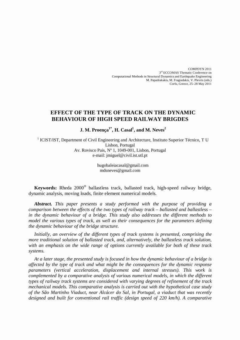
2.2.1. Track characterization The ballastless track is already at the forefront of the Railway Engineering, presenting a
wide range of advantages when compared to the conventional ballasted track. The high demands imposed by high speed railway traffic have provided conditions to invest in a new kind of track with increased performance levels.
Actually, it is especially at high speed that greater benefits can result from the resource to ballastless tracks. This innovative type of railway track stands out mainly for its performance, leading to substantial reductions in maintenance costs and also in maintenance work like tamping, ballast cleaning or track lining. Despite the high initial construction costs, these expenses may be offseted over the service life of the track, creating a more economical and competitive solution when one assesses a broader dimension of time.
Additionally, the problem with drag forces at ballast due to the passage of high speed trains is no more a reason for concern. Indeed, this feature, together with others, has increasingly been providing the application of ballastless tracks on high speed railway lines.
The wide range of different solutions developed by different countries, such as Germany, Japan or even the Netherlands, may eventually hamper the selection process by the designer. In fact, there is a high technical, economical, or even functional ambiguity among the different solutions available.
Nevertheless the Rheda® system may be considered a benchmark for proving its performance and efficiency over the years, having already presented a wide range of applications since its origin.
The cross-section of Rheda 2000® ballastless track used on the Hollandsch Diep Bridge, in the Netherlands, on which this study was also based, is depicted in Figure 4.
Figure 4 – Cross-section of Rheda 2000 ballastless track used on the Hollandsch Diep Bridge (in millimetres).
Adapted from [8].
The Rheda 2000® slab is anchored to the bridge structure in pre-designated free-drilling zones by means of high quality stainless steel dowels with a diameter of 40 mm [8]. An important feature of this connexion is its capacity to allow movements in the longitudinal direction. Thus, the overloading of dowels, as a result of expansion or shrinkage of deck or even track’s concrete, can be avoided [9]. The ballastless track is composed by segmented slabs with a length of 3.50 to 6.40 m. The Rheda 2000® slab used concrete of C35/45 grade for its construction.
Deck
Intermediate geo-textile layer
Dowel2600
232
240
Twinblock sleeper B 355 W60MSleeper spacing: 650 mm
UIC60

J. M. Proença, H. Casal and M. Neves
7
2.2.2. Modelling of the track The ballastless track was considered according to two different approaches:
consideration of the track by means of linear distributed forces; consideration of the track by means of a finite element model, which reproduces the
characteristics of several components of the track. The first procedure was very simple and easy to perform. The inclusion of the ballastless
track in the grid model through its equivalent weight was the basis for this type of representation.
The second procedure, i.e. the numerical modelling, was inspired by the double beam model, a type of representation suggested by several authors [10], [5] and [11] and depicted in Figure 5:
Figure 5 – Schematic representation of the ballastless track model.
The UIC60 rails and the Rheda 2000 slab were modelled using frame elements, while the remainder components were modelled using finite elements that reflect the properties of a viscoelastic material characterized by stiffness and damping values. The longitudinal alignment of the frame elements of the Rheda 2000® slab is not continuous but segmented, with segments of 6.5 m length.
3 PRESENTATION OF THE CASE STUDY
3.1 Presentation of the bridge The case study for the bridge was based on the São Martinho Viaduct, located in the
Natural Reserve of the Sado river estuary, near Alcácer do Sal. This structure is designed to accommodate rail traffic on ballasted track, with a design speed of 220 km/h.
From the structural point of view, the Viaduct is composed of 8 continuous segments, 7 with 4 spans of 28.4 m length each, giving a total length of 113.6 m, and another segment with 56.8 m, consisting of 2 spans of 28.4 m. Only the structural portion of 113.6 m in length will be modelled to study its dynamic behaviour.
The Viaduct cross-section (Figure 6) consists of a prestressed concrete deck, composed of two main beams connected by the railway platform concrete slab. At supports there is a diaphragm with 0.60 m width.
The weight of the deck advocated for this viaduct, including the other permanent loads (except the weight of the railway track), corresponds to 248 kN/m.
Rails
Pads
Rheda 2000 slab
Geo-textile

J. M. Proença, H. Casal and M. Neves
8
Figure 6 – São Martinho Viaduct cross-section (in meters). Adapted from [12].
3.2 Numerical modelling of the bridge São Martinho Viaduct was represented using 4 different numerical models based on finite
elements. These 4 models have undergone a process of evaluation and comparison to indentify which is the best suited for the present study. The models created were:
A numerical model with solid finite elements; A grid numerical model with frame finite elements; A numerical model with shell finite elements; A bar numerical model with frame finite elements.
3.2.1. Model with solid elements This model is composed by solid elements with 8 nodes each. Each node has 3 degrees of
freedom of translation, providing a total of 24 degrees of freedom per element. The size of these finite elements was cleared to ensure a high degree of discretization. In total, 60 530 nodes and 37 540 solid finite elements were used.
This model was considered a reference for the calibration of the remaining models, given its high degree of reliability and given the impossibility of conducting an experimental campaign. For such calibration several static and modal analyses were performed.
This model was not selected to perform the planned dynamic analyses because of the unreasonable calculation times that would otherwise greatly extent the duration this task. This situation would persist even if a coarser discretization was used.
3.2.2. Grid model Regarding the grid model, the Viaduct was modelled in a three-dimensional configuration
with frame finite elements. The two beams were modelled making use of two longitudinal alignments of frame
elements with an appropriate cross-section identical to the beam. The frame elements representing the cantilevers and the top slab between beams were calibrated and transversely aligned, being replicated to a constant value of 0.65 m. Finally, the diaphragms were modelled resorting to the use of frame elements with 0.60 m thick. In total, 3002 nodes and 3243 frame finite elements were used.
2.10 3.104.40 2.00 1.40
13.00
2.70 2.70
0.20
0.20
0.40
1
0.37
0.37
99.435º 96.955º 96.955º 99.435º
2.00
2.00
0.20 0.20 1.001.000.20 0.20

J. M. Proença, H. Casal and M. Neves
9
Figure 7 represents graphically two fundamental mode shapes obtained from modal analysis:
(a) (b) Figure 7 – Graphical representation of the vertical fundamental mode shape (f=4.0271 Hz)(a) and of the
torsional fundamental mode shape (f=7.0443 Hz)(b).
The grid model was selected to perform the desired dynamic study and subsequent dynamic analyses. With a performance very similar to the shell model, regarding the comparison criteria used, this model proved to be a strong option for the realization of dynamic analyses. In addition, the calculation times of this model were likely to be lower than those from the shell model, which did not show other significant advantages. The grid model is the most appropriate, among the four models, to conduct the remaining stages of the desired dynamic study.
3.2.3. Bar model and shell model These models have interesting features and the results are similar to those obtained from
the two models presented above. Regarding the bar (frame) model, the deck was modelled making use of frame finite
elements longitudinally aligned and with an average length of 0.3 m. In order to represent deck areas on piers and on half span, two different cross sections for frame finite elements were defined. In total, 400 nodes and 399 frame finite elements were used.
The bar model was not used to perform dynamic analyses because it is completely unable to effectively represent the torsional behaviour of the Viaduct and, therefore, its torsional mode shapes. This model is not appropriate for the concerned dynamic study since it is not possible to represent, in a reliable way, the effect of the eccentricity of rails.
Regarding the shell model, the beams are represented making use of two longitudinal alignments of shell finite elements classified as “thick” and with a non-constant thickness in order to consider the differences between the bottom and the top of the beam. The top slab between beams and the cantilevers were modelled in a similar way using shell finite elements classified as “thin” and with a non-constant thickness. The diaphragms are represented with shell elements classified as “thin” and with a constant thickness.
In total, this model contains 6825 nodes and 6554 shell finite elements. The shell model could be a viable option, if the grid model did not exist, thanks to the high
degree of reliability of its performance, very close to the model with solid elements. The criteria used for comparison showed few parameters with deviations exceeding 5%. Moreover there is a clear similarity between the first 9 mode shapes and those obtained from the reference model. This option was not used to perform the desired dynamic analyses since it could cause high calculation times. Indeed, as one may know, using shell elements could lead sometimes to a more complex model.

J. M. Proença, H. Casal and M. Neves
10
3.3 Railway track models
3.3.1. Ballasted track models The dynamic analyses of the viaduct can be conducted considering the track as a uniformly
distributed load along the deck or considering a simplified model. Regarding a ballasted track, the EN1991-2 [3] refers that the dynamic analyses should be
performed considering the minimum density of a clean ballast with a minimum depth and a maximum saturation density to a dirty ballast taking into account the probable increase on depth of ballast layer. The present study was performed considering a depth of ballast of 350 mm and two different ballast densities ρballast = 17 kN/m3 and ρballast = 20kN/m3. Table 1 presents the weight of the ballasted track on the Viaduct.
Typology Properties Weight (kN/m)
Ballasted track (double track) Model BT1 (ρballast=17 kN/m3) 95 Model BT2 (ρballast=20 kN/m3) 112
Table 1 – Different typologies of ballasted track considered and its weight per linear meter on the Viaduct.
Regarding the models of ballasted track, Table 2 shows the parameters used on the study of the influence of the various elements of this type of track in the dynamic behaviour of the structure. The geometry of the ballasted track as well as the ballast properties are related to the properties of model BT2.
3.3.2. Ballastless track models In similarity to the ballasted track, the dynamic analyses were also performed considering
the ballastless track by means of linear distributed forces and by means of a simplified finite element model.
The Rheda 2000® ballastless track (double track) highlighted in this paper has a weight per linear meter of 35 kN/m [8].
With regard to the track model, the properties of the frame elements are shown in Table 2:
Parameters of the railway track Symbology
Value
Non-vibrating ballast
Vibrating ballast
Ballastless track
UIC60 Rail
Cross section Sr [cm2] 76,86 76,86 76,86 Mass mr [kg/m] 60,34 60,34 60,34
Elasticity modulus Er [GPa] 210,00 210,00 210,00 Poisson’s ratio νr [-] 0,30 0,30 0,30
Vertical bending inertia Ixx [cm4] 3050 3050 3050 Lateral bending inertia Iyy [cm4] 515,60 515,60 515,60
Pad Dynamic stiffness Kp (MN/m) 65 [13] 65 Variable
Damping Cp (kNs/m) 5,50 [13] 5,50 Variable
Sleeper Mass Ms [kg] 300 300 -
Spacing ls [m] 0,60 0,60 0,65
Ballast Vertical stiffness Kb [N/m] 3,30E08 3,30E08 -
Damping Cb [Ns/m] 1,20E05 [6] 1,20E05 - Vibrating mass Mb [kg] - 770,94 -
Connexion Vertical stiffness Kbp [N/m] - 1000E06 [6] -

J. M. Proença, H. Casal and M. Neves
11
Parameters of the railway track Symbology
Value
Non-vibrating ballast
Vibrating ballast
Ballastless track
ballast/deck Damping Cbp [Ns/m] - 50E03 [6] -
Rheda2000® slab
Specific weight ρL [kN/m3] - - 26,37 Length x Height Lxh [mxm] - - 2,60x0,24
Elasticity modulus EL [GPa] - - 34,00 Poisson’s ratio νL [-] - - 0,20
Geo-textile Vertical stiffness KGt [GN/m/m] - - 20E03
Damping CGt[GNs/m/m] - - 20
Table 2 – Parameters used in the ballasted and ballastless models.
4 DYNAMIC ANALYSES
4.1 General considerations The dynamic analyses were performed according to the following assumptions: • The method of modal superposition was applied, considering a number of frequencies and
associated mode shapes on the analysis up to the greater of 30 HZ, as recommended in EN1990-A2 [14];
• The structural damping was simulated using the Rayleigh damping; • The used time step was Δt = 0.005 s; • The range of speeds used was 140 km/h to 420 km/h with a speed step of Δv=10 km/h; • Only the 4th span of the Viaduct was assessed.
4.2 Results of the ballasted track models This subsection presents the results of the dynamic analyses performed, making use of the
grid model with and without the ballasted track model. The load models were regarded as moving loads. The realized parametric study aims to assess the effect of the various components of the track in the dynamic behaviour of the support structure.
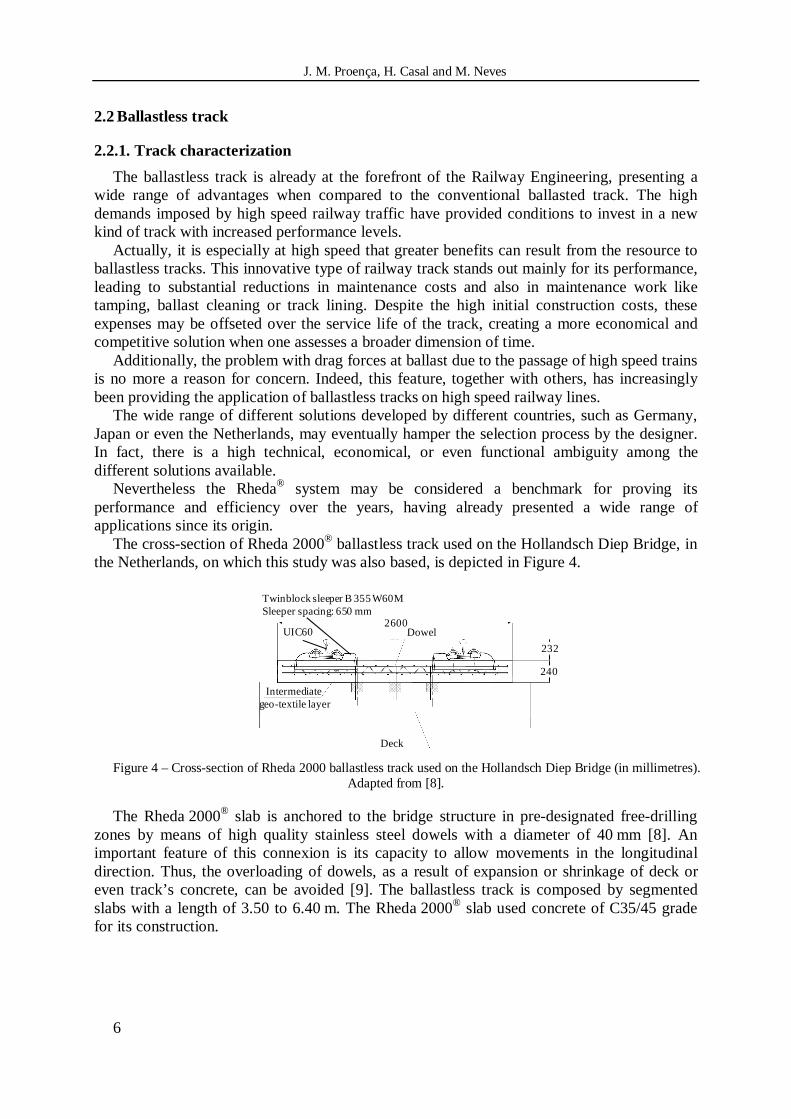
4.2.1. Grid model without the ballasted track model The envelope of accelerations and displacements, depicted in Figure 8, were obtained for
all the ten HSLM-A defined in EN1991-2 [3] and making use of the grid model without the track model (BT1).
J. M. Proença, H. Casal and M. Neves
12
(a) (b) Figure 8 – Envelope of accelerations (a) and envelope of displacements (b) for the passage of the HSLM-A
The following conclusions were drawn: • a maximum vertical acceleration peak of av=4,38 m/s2 occurs for the load model
HSLM-A7; • a maximum vertical displacement peak of δv = 0,0111 m occurs for the load model
HSLM-A10; • the limit of 3,5 m/s2 for the acceleration of ballasted tracks, defined in EN1990-A2
[14], was exceeded; • the maximum limit of δlim=L/600 for the vertical displacement, defined in EN1990-A2
[14], was never exceeded. With regard to the model BT2 and in comparison with the results obtained for the model
BT1, a maximum vertical acceleration is obtained with a lower value but occurring also for a lower resonance speed. On the contrary, the maximum vertical displacement is not influenced by the variation of the weight of the track.
4.2.2. Grid model with the ballasted track models The results presented in Table 3 correspond to the values of the first 5 natural frequencies
of the structure with and without consideration of the ballasted track models. There are minor variations of the values in each vibration mode shape and on the first mode shapes this variation is barely perceptible. Such results do not demonstrate a contribution of the ballasted track properties for the overall behaviour of the structure. Analyzing the Figure 9 it is of clear understanding that a superposition of the obtained results exists, not only for the maximum vertical accelerations but also for the maximum vertical displacements along the load path, to the considered speed range. It is concluded, though, that the consideration of the ballasted track models does not change the structural response when the dynamic analysis are limited to lower than 30 Hz mode shapes. To the viaduct modelled with a span length of L=28.4m the distribution of the loads along various sleepers resulting from the track models, does not contribute to the acceleration reduction nor to the structures’ displacements.
0.00.51.01.52.02.53.03.54.04.55.05.5
140 180 220 260 300 340 380 420
Ace
lera
tion
[m/s
2 ]
Speed [km/h]
Maximum accelerations - BT1HSLM-A10HSLM-A9HSLM-A8HSLM-A7HSLM-A6HSLM-A5HSLM-A3HSLM-A4HSLM-A2HSLM-A1
0.0020.0030.0040.0050.0060.0070.0080.0090.0100.0110.012
140 180 220 260 300 340 380 420
Dis
plac
emen
t (m
)
Speed [km/h]
Maximum displacements - BT1HSLM-A10HSLM-A9HSLM-A8HSLM-A7HSLM-A6HSLM-A5HSLM-A4HSLM-A3HSLM-A2HSLM-A1

J. M. Proença, H. Casal and M. Neves
13
Mode shape of vibration
Vibration frequency[Hz]
BT2 Model
Vibrating ballast
Non-vibrating
ballast 1 3,058 3,059 3,059 2 3,600 3,600 3,600 3 4,653 4,653 4,654 4 5,132 5,146 5,147 5 5,222 5,236 5,237
Table 3 - Comparison of the vibrating frequencies of the viaduct with and without the consideration of the ballasted track models.
(a) (b) Figure 9 – Envelope of accelerations (a) and envelope of displacements (b) for the HSLM-A8, considering
three different possibilities for the inclusion of the ballasted track
In fact, calculating the vibration fundamental frequencies of the ballasted track and assuming a simplified SDOF model graphically represented in Figure 10, a fundamental frequency of vibration of 115Hz has been computed, thus largely exceeding the 30 Hz limit of vibration mode shapes to be considered in the dynamic analyses. Barbero [15] has reached similar conclusions and noticed that the railway vibrates jointly with the bridge when the vibration frequencies of the track are much higher than those of of the bridge.
Dynamic analyses considering a more flexible ballasted track were also performed. Nevertheless, the obtained results did not show different variations.
Figure 10 – Model with three degrees of freedom representative of the behaviour of the ballasted track.
0.0
1.0
2.0
3.0
4.0
5.0
140 180 220 260 300 340 380 420
Acc
eler
atio
n [m
/s²]
Speed [km/h]
Maximum accelerations - HSLM-A8Without track model BT2With track model - non-vibrating ballastWith track model - vibrating ballast
0.000
0.002
0.004
0.006
0.008
0.010
0.012
140 180 220 260 300 340 380 420
Dis
plac
emen
t [m
]
Speed [km/h]
Maximum displacements - HSLM-A8Without track model BT2With track model - non-vibrating ballastWith track model - vibrating ballast
q1
q2
q3
Rail
Sleeper
Ballast
M3
M2
M1
K3
K2
K1

J. M. Proença, H. Casal and M. Neves
14
4.3 Results of the ballastless track model This subsection presents a comparative study that aims at evaluating the dynamic
behaviour of the Viaduct taking into account the type of representation chosen for the ballastless track
4.3.1. Grid model without the ballastless track model The envelope of accelerations and displacements, depicted in the Figure below, were
obtained for all the ten HSLM-A defined in EN1991-2 [3] and making use of the grid model without the track model:
(a) (b)
Figure 11 – Envelope of accelerations (a) and envelope of displacements (b) for the passage of the HSLM-A.
As it can be observed: • the maximum acceleration and displacement occur for the HSLM-A10, which induces
dynamic responses with quite significant resonance peaks; • a maximum acceleration of 4.613 m/s2 and a maximum displacement of 0.01062 m
were computed; • the serviceability limit of 5 m/s2 for the acceleration of ballastless tracks, defined in
EN1990-A2 [14], was never exceeded; • the maximum limit of δlim=L/600 for the vertical displacement, defined in
EN1990-A2 [14], was never exceeded.
4.3.2. Grid model with the ballastless track model Regarding the grid model with the track model, a parametric study was performed
considering the properties of the pads, such as the dynamic stiffness and damping, assigned with the values present in Table 4.
0.00.51.01.52.02.53.03.54.04.55.0
140 180 220 260 300 340 380 420
Acc
eler
atio
n [m
/s²]
Speed [km/h]
Maximum accelerationsHSLM-A1HSLM-A2HSLM-A3HSLM-A4HSLM-A5HSLM-A6HSLM-A7HSLM-A8HSLM-A9HSLM-A10
0.0000.0010.0020.0030.0040.0050.0060.0070.0080.0090.0100.0110.012
140 180 220 260 300 340 380 420
Dis
plac
emen
t [m
]
Speed [km/h]
Maximum displacementsHSLM-A1HSLM-A2HSLM-A3HSLM-A4HSLM-A5HSLM-A6HSLM-A7HSLM-A8HSLM-A9HSLM-A10

J. M. Proença, H. Casal and M. Neves
15
Grid model Pads
Dynamic stiffness kd,p [kN/m]
Damping cp [kNs/m]
With track model 1 100000 15 With track model 2 100000 75 With track model 3 100000 500 With track model 4 30000 15 With track model 5 30000 75 With track model 6 30000 500 With track model 7 ∞ —
Table 4 – List of models tested with distinct properties for the pads.
Figure 12 shows the results obtained from the dynamic analyses performed for the HSLM-A10:
(a) (b) Figure 12 – Envelope of accelerations (a) and displacements (b) for the passage of the HSLM-A10, obtained
from the grid model with track model 1-7 and from the grid model without the track model.
As it can be observed, and regarding the 7 models tested, the graphical representations of the envelopes are indistinguishable from each other. The variation of the properties of the pads between the different proposed values does not cause any substantial change in the response of the global structure.
Furthermore, the envelope of accelerations and displacements display deviations when compared to those obtained from the grid model without the track model. However, the configuration of these envelopes still exhibits an obvious similarity.
Similar conclusions were drawn after a parametric study assessing the influence of the geo-textile.
By comparing the dynamic responses of the grid model without the track model and the grid model with the track model it can be concluded that the main differences recorded are due to the frame elements used to represent the rails and the Rheda 2000® slab. In fact, these elements add an extra stiffness in the structure. Naturally, such stiffness is not taken into account in the grid model without the track model. This extra stiffness will appreciably change the dynamic response of the structure since these elements absorb some of the load of the vehicles.
Consequently, it is useful to assess the degree of stiffness of the ballastless track since such stiffness might influence the dynamic response of the structure.
0.00.51.01.52.02.53.03.54.04.55.05.5
140 180 220 260 300 340 380 420
Acc
eler
atio
n[m
/s2 ]
Speed [km/h]
Maximum accelerations - HSLM-A10Without track modelWith track model 1With track model 2With track model 3With track model 4With track model 5With track model 6With track model 7
0.000
0.002
0.004
0.006
0.008
0.010
0.012
140 180 220 260 300 340 380 420
Dis
plac
emen
t[m
]
Speed [km/h]
Maximum displacements - HSLM-A10Without track modelWith track model 1With track model 2With track model 3With track model 4With track model 5With track model 6With track model 7

J. M. Proença, H. Casal and M. Neves
16
4.4 Comparative assessment of the type of track Aiming for a comparative analysis of the two types of track, it will be taken into account
the influence of the weight of the tracks and the influence of the modelling of the tracks in the dynamic response of the structure.
To assess the influence of the weight of the tracks, two grid models without the ballasted track model (BT1 and BT2 with different weights) and the grid model without the ballastless track model (BLT), were considered.
Figure 13 shows the results obtained from the dynamic analyses performed for the HSLM-A10:
(a) (b) Figure 13 – Envelope of accelerations (a) and displacements (b) for the passage of the HSLM-A10, obtained
from the grid model without ballastless track model (BLT) and from the grid models without ballasted track model (BT1 and BT2).
As it can be observed, the envelopes of accelerations and displacements are lagged, despite the obvious similarity in their configurations. Thus, the lighter the track is, the more to the right the resonance peaks will be shifted, which will correspond to higher speeds. Furthermore, the lighter the track is, the higher the accelerations peaks will be. In structures with a lighter track one might avoid resonance peaks recorded in structures with heavier tracks if such peaks occur outside the range of speeds analysed.
With Figure 9 and Figure 12 the influence of the modelling of the tracks may be assessed. As can be seen, and contrarily to what occurs in the case of the ballastless track, the ballasted track considered by means of a track model with vibrating ballast or non-vibrating ballast does not cause significant changes in the dynamic response obtained from the grid model without the track model.
This happens because the models with vibrating and non-vibrating ballast are prone to vibrate for frequencies above the limit of 30 Hz, imposed by the EN1990-A2 [14] to determine the dynamic response. Furthermore, it is not considered the shear stiffness of the ballast. Therefore, the ballasted track models added just a small extra stiffness in structure. Such stiffness is related to the rails. This small stiffness increment causes virtually no effect in the dynamic response of the structure.
The ballastless track models also tend to vibrate for high frequencies. However, the Rheda 2000® slab adds a significant stiffness in structure.
0.0
1.0
2.0
3.0
4.0
5.0
140 180 220 260 300 340 380 420
Acc
eler
atio
n [m
/s²]
Speed [km/h]
Maximum accelerations - HSLM-A10Without track model BLTWithout track model BT1Without track model BT2
0.000
0.002
0.004
0.006
0.008
0.010
0.012
140 180 220 260 300 340 380 420
Dis
plac
emen
t [m
]
Speed [km/h]
Maximum displacements - HSLM-A10Without track model BLTWithout track model BT1Without track model BT2

J. M. Proença, H. Casal and M. Neves
17
5 CONCLUSIONS By assessing the influence of the type of railway track in the dynamic response of the bridge, some conclusions can be drawn: • When a lighter track is used, the resonance peaks will occur at higher speeds. It is possible
to avoid resonance peaks occurring in structures with heavier tracks if a lighter track is used and if such peaks occur outside the range of speeds analysed;
• The lighter the track is, the higher the resonance peaks will be; • The modelling of the ballasted track does not significantly influence the dynamic response
of the global structure when obtained from a grid model without a ballasted track model. On the contrary, such dynamic response may be affected if a ballastless track model is used;
• The increment of stiffness provided by the track is an important feature distinguishing the models of the two types of railway track;
• The railway track models presented tend to vibrate for frequencies above the limit of 30 Hz, advocated by the EN1990-A2 [14] to determine the dynamic response.
6 ACKNOWLEDGMENTS This study was developed under the co-operation protocol celebrated between IST and
Rave in May 2007 and renewed in April 2010. The purpose of this protocol is to support the Portuguese national high-speed railway project with a set of recommendations for the structural design, particularly in what concerns the railway track.
The authors would like to thank GRID, specially Professor Antório Reis and Eng. Nuno Lopes, for supplying valuable data related to the case study. They would also like to send their appreciation to Eng João Francisco Henriques for his generosity in handing out his pre-process computation, which has proved to be very useful for the dynamic analysis. The opinion and relevant published work of Professor Rui Calçada are also gratefully acknowledged.
7 REFERENCES
1 Gil, A.F. and Fernández, M. G. Track Performance on New High Speed Lines in Spain. In Track for High-Speed Railways, Porto: Feup, 2006.
2 Teixeira, P. F. Contribución a la Reducción de los costes de Mantenimiento de Vías de Alta Velocidad Mediante la Optimización de su Rigidez Vertical. Universidade Politécnica de Catalunha, Barcelona, 2003.
3 EN1991-2. Eurocode 1: Actions on structures - Part2: Traffic loads on bridges. European Committee for Standardization (CEN), Brussels, 2003.
4 Calçada, R. Efeitos dinâmicos em pontes resultantes do tráfego ferroviário a alta velocidade. FEUP: Faculdade de Engenharia do Porto, Porto, 1996. MSc. Thesis.
5 De Man, Amnon P. A survey of dynamic railway track properties and their quality. Technische Universiteit Delft, Delft, 2002. PhD thesis.
6 ERRI Specialists' Committee D214/RP 9. Final Report - Rail Bridges for Speeds > 200 km/h. European Rail Research Institute , Utrecht, 2001.
7 Zhai, W., Wang, K., and Lin, J. Modelling and experiment of railway ballast vibrations (2004), 673-683. 8 Tünnissen, Joep T. F. M. Dynamic Aspects of the High-Speed railway Bridge Across the Hollandsch Diep. In
Workshop Track-Bridge Interaction on High-Speed Railways. FEUP, Universidade do Porto, Porto, 2007. 9 Infraspeed. High Speed in the Low Lands. Infraspeed, Zoetermeer, 2006. 10 Esveld, Coenraad. Modern Railway Track. MRT-Productions, Technische Universiteit Delft, 2001. 11 Varandas, José, Dimitrovová, Zuzana, Palácio, Alberto, and da Silva, Manuel. Influência da rigidez da
fundação no valor da velocidade crítica de uma carga móvel. Aplicação a vias ferroviárias. UNIC Centro de Investigação em estruturas e Construção da UNL, 2007.

J. M. Proença, H. Casal and M. Neves
18
12 Reis, A. J., Lopes, N. T., and Ribeiro, D. Track-Structure Interaction in Long Railway Bridges. In Workshop Track-Bridge Interaction on High-Speed Railways. FEUP, Universidade do Porto, porto, 2007.
13 Kaewunruen, S. and Remennikov, A.M. An Alternative Rail Pad Tester for Measuring Dynamic Properties of Rail Pads Under Large Preloads. Experimental Mechanics, 48 (2007), 55–64.
14 EN1990-A2. Eurocode: Basis of structural design - Annex A2: Applications for bridges (Normative). European Committee for Standardization (CEN), Brussels, 2005.
15 Barbero, J. D. Dinámica de puentes de ferrocarril para alta velocidad: métodos de cálculo y estudio de la resonancia. Escuela Técnica Superior de Ingenieros de Caminos, Canales y Puertos de Madrid, Madrid, 2001. Tesis Doctoral.
16 Casal, Hugo. Comportamento Dinâmico de Pontes Ferroviárias de Alta Velocidade com Via Não Balastrada. IST, Lisboa, 2010b. Dissertação de mestrado integrado em Engenharia Civil.
17 Neves, Marco. Comportamento Dinâmico de Pontes Ferroviárias de Alta Velocidade com Via Balastrada. IST, Lisboa, 2010. Dissertação de mestrado integrado em Engenharia Civil.