Embed Size (px)
Citation preview

ON THE ROLE OF OIL-FILM BEARINGS IN PROMOTING SHAFT INSTABILITY:
SOME EXPERIMENTAL OBSERVATIONS
R.Holmes
School of Engineering and Applied Sciences
University of Sussex,
Falmer, Brighton, Sussex,
U.K. BNI,9QT
SUMMARY
An insight into the mechanism of oil whirl instability is obtained by in-
vestigating theoretically and experimentally its occurrence in rigid and flex-
ible rotor systems. Means of damping against such instability are applied inthe latter case and their effectiveness discussed.
INTRODUCTION
For a rotating shaft supported in oil-film bearings the instability onset
speed depends,to a large extent, on the nature of the hydrodynamic forces pro-
duced in the bearings. Oil whirl instability is characterized by shaft vibra-
tion frequency and amplitude and the purpose of this paper is to report the
effect of various bearing parameters on the oil-whirl frequency and amplitude
of rigid and flexible shafts supported on fluid-film bearings.
In order to provide a qualitative understanding of such instability the
particular extreme cases of a very short bearing and a very long bearing areconsidered.
A physical insight into the mechanism of oil-whirl instability can be ob-
tained by considering Fig.l. As a result of the application of an external
load the journal deflects on the oil film rather as it would on a spring. Con-
sequently, a converging wedge is formed in the region of contracting film thick-
ness into which oil is dragged by journal rotation, _. Pressure is thus genera-
ted in the oil by hydrodynamic action to counteract the external load. The
average angular velocity of this oil is about half rotational speed and, should
any disturbance to the journal centre cause the line of centres to rotate at
this angular velocity, then the wedge into which the oil is dragged will move
away from the oil at the same velocity, with the result that no hydrodynamic
pressure will be generated. The journal thus loses its load-carrying capacity
and may become unstable in a whirling motion, the energy for the instability
being fed by its own rotation.
345
https://ntrs.nasa.gov/search.jsp?R=19800021225 2020-05-11T08:09:18+00:00Z

Fig. I: Forces on journal Fig.2: Magnified portion of Fig. 1
a
b
C
CI
D
F
Damper location
Damping coefficient
Radial clearance
Constant
Diameter
Static external load per land
FI,F 2 Oil film forces
gh
inHg
S
m
n
n
o
P
Gravitational constant
Film thickness at angular co-
ordinate _ = c(l + n cos 8).
Inches of mercury
Journal length
Shaft span
Rotor mass per bearing land
Eccentricity ratio = _/c
Static eccentricity ratio
Hydrodynamic pres sure
NOTATION
P F/mcw 2
R = D/2 Journal radius
t Time
z Axial co-ordinate
Constant
Constant
E Eccentricity of journal at instant
considered
Lubricant viscosity
Angle between static load line and
line of centres of journal and bear-
ing
_o Attitude angle under static con-ditions
w Journal angular velocity,forcing
frequency
Angular velocity of whirl
_I Lowest pinned critical speed of shaft!2
bD'I (_) where b is external_D,I - m D,I
or internal damping(') d/d (_t)
346

Centres Load numbers
C B
CjD
CjS
Bearing centre L2_
Centre of dynamic journal at in-
stant considered
Centre of journal under static load $2_
only
Load number for long 360 ° film
= Fc2/2_wR 3.
Load number for short 360 ° film
= 4_Fc2/_R_3w
THEORETICAL TREATMENT
In the region of diverging film boundaries the hydrodynamic pressure becomes
negative and, should the supply pressure be insufficient to maintain a net pres-
sure in the oil of greater than absolute zero then cavitation will usually re-
sult. However, in some cases of lightly loaded bearings a full 360 ° film of oil
is maintained. Not unexpectedly, the spring-like and damping properties of the
oil film depend to a large extent on the degree of cavitation present. The
equation which governs the generation of hydrodynamic pressure is due to Osborne
Reynolds and cannot be solved analytically for the journal bearing situation.
However, if one of two approximations is made then a analytical solution is
obtainable. These approximations are based on the assumptions that the oil film
length in relation to its diameter is (I) very short and (2) very long. These
solutions give a good insight into the characteristics of journal bearing oil
films. The hydrodynamic forces generated by the short uncavitated oil film
(Fig.l) are (Ref.l)
- R_ 3 _(i + 2n 2)F1 - 3 Dcn"
c (i - n2) 5/2
F 2 = R_ 3 _cn_(w - 25)/2c3(i - n2) 3/2
Under conditions of static load,
dn $ and thusd--t-and are zero, n = no
F 1 = 0
2 3/2F 2 = R_3_cn _w/2c3(I - n )
O O
Also, F 2 = F and _ = _/2 (Fig.l).
Therefore 2_2n /(i - n 2)3/2 = 4_Fc2/DR_3wO O
Let 4_Fc2/_R_3w be called the 'short 2_' load number, given the symbol $2_.
becomeIn terms of static eccentricity ratio, no and static load,F, F 1 and F 2 (Fig.2)
2)3/2F I = - 2F(I - n (I + 2n2)_/wn (I - n2) 5/2and o o
2 _ n2)3/2F 2 = F(w - 25)(1 - n )3/2n/wn (IO O
347

the corresponding expressions for the long bearing are as follows:
F (I_n2)3/236_2noF _ "
F (2+n 2)(l_no 2)_ ( _ ) n lo " (2+n2) (l_n2)_
and a 'long 2z' load numbermaybe defined having the value
F¢2 _ 6Zno _ $2_ .(_)
L2_ 2_R3_w (2 + n (I - n- 2) 2)_ 2_o o
NON-LINEAR EQUATIONS OF RIGID ROTOR MOTION
Consider a symmetrical rigid rotor of mass 2m symmetrically supported on two
similar, full-film bearings. From Fig. 1 the equations of motion are
F 1 + F cos 0 = mc(n - n_ 2)
F 2 - F sin _ = mc(n_ + 2n$)
These equations become, in non-dimensional form,
F 1
2mcw
+ P cos 0 = n" - n0 '2
F2
P sin _ = nO" + 2n'_'2
mcw
where P = F/mcw 2 and n' = dn/d(wt) etc.
(1)
The following general conclusions may be made from the numerical solutions
of equations (i), which result in unstable transient spirals (Fig.3):
(i) The number of loops within a given radius of the static equilibrium position
is governed to a large extent by the value of P, the number of loops increas-
ing with rising values of P. A similar less pronounced effect is noted as
n decreases. Roughly similar numbers of loops are produced by either theory
u_til the bearing centre is enclosed. After this point, the orbits tend to
close up and the short bearing solution does so much more rapidly.
348

The shape of the initial loops is largely dictated by the value of n . In• O .
general, as n is increased, these loops become elongated in the dlrectlon
of the extern°l load and ultimately may assume a crescent form. Although
not restricted to the short bearing solution this distortion is far more
pronounced for the case of the short bearing solution than for the long.
Another general conclusion of some interest is that for both the long
and short bearing theories the whirl frequency approaches half rotational
speed as the eccentricity ratio approaches unity, this approach being at an
ever-decreasing rate.
(2) The magnitude of the initial displacement used to commence the solutions has
a pronounced effect on the position of loops for solutions having few loops,
for example, for low values of P. This effect becomes less apparent as thevalue of P is increased.
Some general considerations of the equations of motion
One of the main interests attached to the non-linear equations of motion is
whether they predict the possibility of a closed orbital motion of the journal
centre within the clearance circle. A closed circular orbit concentric with
the bearing centre is not possible except for the hypothetical case of a mass-
less rotor, since n and hence F 1 and F 2 would be zero, giving no force to coun-
teract the centrifugal force of this postulated whirl. From digital computation
with a wide range of parameters it appears that if any other form of closed
orbit exists it will occur as n + I, n' + O and _' + 0.5. As an approximation
these trends were placed in the equations of motion (i).
Experiment
Short bearing
theory
Fig.3: Experimental and
theoretical trans-
ients.
Left-hand column
P = 0.2, n = 0.4o
Right-hand column
P = 2.5, n o = 0.6
Long bearing
theory
349

These give on integration
n _i- 1
i+_(5-i) _-_+ 2sin
cI being a constant of integration and B = 2.5 (short) and 1.5 (long).
Thus n asymptotically approaches unity and it appears that, in general,closed orbits are not possible for t < _, with the exception of the particularcase of P = _ when the integral oscillates between fixed limits. This corres-ponds to the massless rotor of Swift (ref.3). It maybe seen that dn/dt iscurbed more rapidly as n increases, since the exponent _ is greater than unity.Further, since B is larger for the short bearing than for the long bearing thecurbing for the former is the more pronounced.
Experimental rotor
The motion of an experimental rotor was monitored by pick-ups mounted in
the horizontal and vertical planes of the rotor axis and located midway between
the bearings. This motion was displayed on a storage oscilloscope and the
stored trace was photographed directly when required. This technique allowed
the clearance circle to be conveniently displayed by rolling the rotor within
the bearing shells. On increasing the rotor speed from zero, an eccentricity
locus was traced out on the oscilloscope until the attitude angle _o reached
90 ° , when the rotor became unstable• In view of the low supply pressure in
relation to the load pressure this suggested the presence of an oil film sup-
porting sub-atmospheric pressures. In order that different values of P could
be inspected, oils of different viscosities were used. This ensured different
whirl-onset speeds• When it was required that values of P should be small (high
whirl-onset speeds), then the rotor was run up to the required speeds with the
supply pressure at approximately 0.5 inHg, being suddenly increased to 6 inHg
to give a 90 ° attitude angle and to initiate whirl. Some comparisons of experi-
mental results with the equivalent short and long bearing solutions are shown in
Fig. 3. For the case of low P, it may be observed that the photograph shows a
small white area corresponding to an attitude angle between O ° and 90 ° . This
represents a running condition which occurred due to starving the bearings of
oil prior to imposing the full supply pressure of 6 inHg. In both the photographs
the outer circle denotes the clearance circle• Pick-up non-linearities and the
necessary pedestal clamping forces probably contribute to the non-circularity of
this clearance circle•
In this experimental work, not only are the initial conditions unknown but
they may correspond to an appreciable disturbance for low values of P. Hence
although qualitative behaviour may be determined using such values, those likely
to show some quantitative agreement with theory are for higher values of P, these
being largely unaffected by the initial conditions• Such a case is that corres-
• =0.6ponding to P = 2 5, n o
Bearing these comments in mind, the experimental results support the theoret-
ical solutions in the following respects:
350

(I) The numberof loops increases as P is increased for a _iven value of n . AO
similar less pronounced effect is obtained on reduction of n o for a
given P.
(2) As n is increased, the loops become elongated in the external load direc-
tion°and can even assume a crescent form.
(3) As the whirl develops the loops become roughly circular in form around the
bearing centre.
There is also a general tendency to support the short bearing theory for
the initial growth pattern and final decay pattern while the intermediate
loops, particularly in distribution, approximate more closely to the long bear-
ing solutions.
One important difference between the computed and experimental spirals is
that the former tend to have slightly fewer loops and proceed to bearing con-
tact as time tends to infinity. In the experimental work, bearing contact was
never experienced, a closed orbit within the clearance circle always being
established. The reasons for this are not clear, though the supply pressure
and groove geometry were found to be important factors and it was noted that
the size of the final orbit could be reduced by increasing the supply pressure.
As the eccentricity ratio approaches unity, its first derivative approaches
zero and the frequency ratio approaches 0.5, then the peak negative pressure is
reduced in magnitude. Thus a reduction below the whirl onset speed and/or onset
supply pressure is required to cause cavitation and thus quell any already-
existing whirl. This probably accounts for the frequently observed 'hysteresis
effect'
Some interesting conclusions can be drawn from the application of a linearis"
ing technique to the oil-film forces F 1 and F2, and using these forces to es-
tablish a frequency equation for the rigid test rotor. From this equation the
frequency ratios of incipient oil-whirl instability were found and plotted in
Figs. 4 and 5. The corresponding experimental plots relating to the observed
limit cycles are sho_ in Fig.6 and show good qualitative agreement.
Whilst an uncavitated oil film promotes instability, this is not always the
case for a cavitated film. Instead instability for small (ref.2) and large
(ref.4) perturbations is predicted in a region defined by eccentricity ratio and P.
) 0;2 0;4 no 0;6
04 .. _ -__-__,
nlO 3 ............_ .... -i----_
0 2 _'_0 04 _ --:
0.1; ,F/mdw2:...... 0.02, ' --'0 4 8 12 16{_20 24
Fig.4: Short bearing
f r
"---,._ <::.-04..0.2 _ _ -----._.._t,.
0-1 _/mc_°__'-_-_)'-'_0 I 2 3 4_5 6
Fig. 5:Long bearing
351
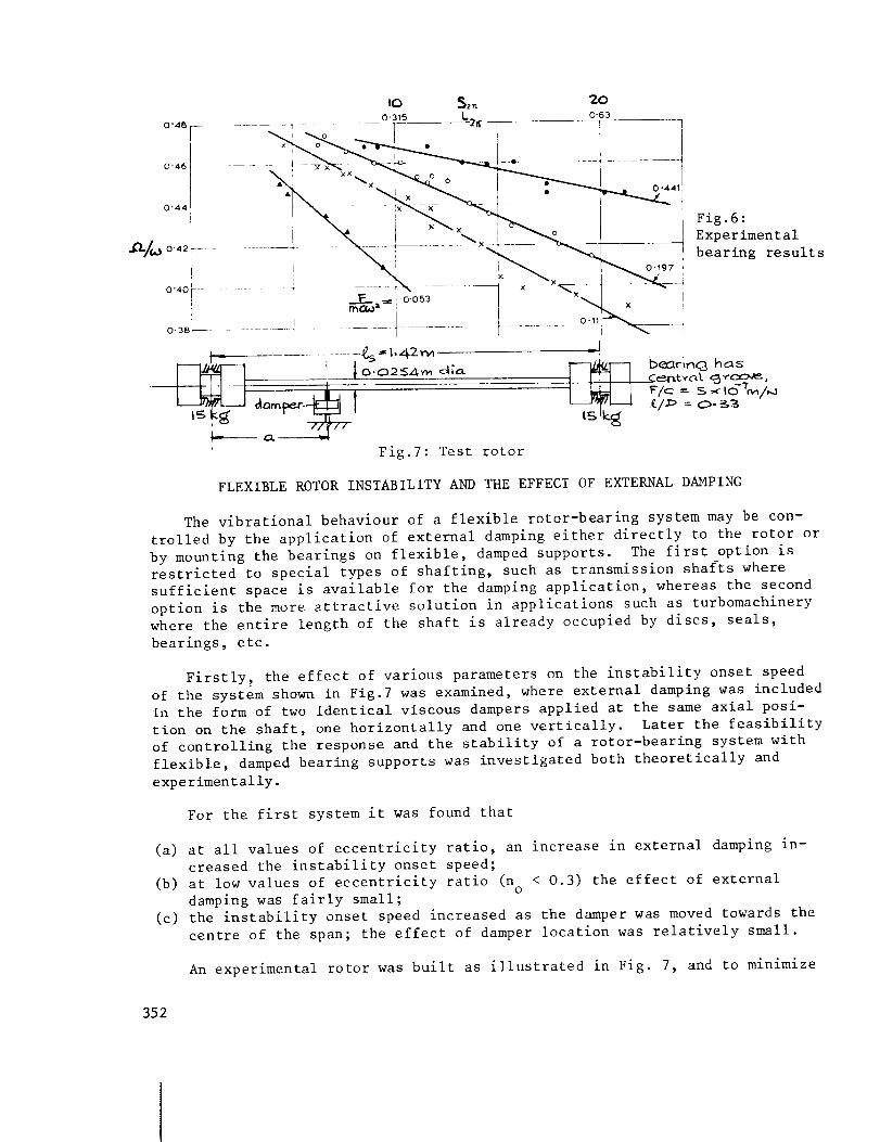
' Fig.7: Test rotor
Fig.6:
Experimental
bearing results
l__beorln<_ h _ s
/.m = O- _ -
FLEXIBLE ROTOR INSTABILITY AND THE EFFECT OF EXTERNAL DAMPING
The vibrational behaviour of a flexible rotor-bearing system may be con-
trolled by the application of external damping either directly to the rotor or
by mounting the bearings on flexible, damped supports. The first option is
restricted to special types of shafting, such as transmission shafts where
sufficient space is available for the damping application, whereas the second
option is the more attractive solution in applications such as turbomachinery
where the entire length of the shaft is already occupied by discs, seals,
bearings, etc.
Firstly, the effect of various parameters on the instability onset speed
of the system shown in Fig.7 was examined, where external damping was included
in the form of two identical viscous dampers applied at the same axial posi-
tion on the shaft, one horizontally and one vertically. Later the feasibility
of controlling the response and the stability of a rotor-bearing system with
flexible, damped bearing supports was investigated both theoretically and
experimentally.
For the first system it was found that
(a) at all values of eccentricity ratio, an increase in external damping in-
creased the instability onset speed;
(b) at low values of eccentricity ratio (no < 0.3) the effect of externaldamping was fairly small;
(c) the instability onset speed increased as the damper was moved towards the
centre of the span; the effect of damper location was relatively small.
An experimental rotor was built as illustrated in Fig. 7, and to minimize
352

external damping, the bearings had no seals and there were no axial thrust bear-
ings. A pair of variable external dampers were mounted in the horizontal and
vertical planes at one adjustable point on the shaft.
Fig.8: Experimental recordings
For running speeds below the transition range the shaft vibration was lin-
ear and harmonic, with no trace of non-synchronous vibration. Fig. 8a shows a
typical motion of the journal centre, within its clearance circle, when the
shaft speed was increased from zero to 250 rev/min. From its lowest position,
corresponding to an eccentricity ratio of unity and a zero attitude angle, the
journal acquired a stable operating position, characteristic of a cavitated
oil film. Fig. 8b shows a typical journal orbit for a much higher running speed,
still well below the transition range. Here the journal is performing a very
small, almost circular, synchronous orbit, due to slight mass unbalance and
lack of straightness of the shaft. In this figure (and in Fig. 8c and d), the
horizontal and vertical lines are radius lines of the clearance circle.
For running speeds within the transition range the shaft exhibited a com-
bination of synchronous and non-synchronous vibration, which showed no tendency
to either build-up or decay with time. The non-synchronous vibration had a
frequency equal to the first critical speed of the shaft (i.e. its first pinned
natural frequency). Fig. 8c and d show typical journal orbits encountered when
running in the upper part of the transition range. Here the bearing conditions
were such that the ratio of synchronous to non-synchronous frequencies was about
2:1, which accounts for the double-loop character of the journal orbits. Another
353

exampleof a shaft orbit occurring in the transition range is shownin Fig.Be. Here bearing conditions are such that the synchronous frequency is aboutthree times the non-synchronous frequency. In all the cases observed it wasfound that, in the transition range, the journal orbits always centred on aposition characteristic of a cavitated oil film, i.e. at a position well belowthe horizontal line through the centre of the clearance circle. This was animportant observation since it showedthat oil whirl did not commenceas aresult of the bearing oil films acquiring a full 360° extent. The complexcharacter of the vibration in the transition range is clearly illustrated byFig. 8f, which showsa typical variation of the horizontal componentof theshaft motion with time.
1'8--
16
12
10
0 0.1 0-2 06 0.703 03n05
2
08
0_o-- 5.2x10⁻³.-. _Z :0
3 2(_v°- 5'2 x10³-_,_ =2-8x10=
® o.o_,, 2-8x10⁻³
Experimenfui• UD =0
× vo=5-2xI0-_
Fig.9: Instability onset speeds
FOr_D=O,that is no external damping, the experiment_lly determined non-
dimensional instability onset speed ratios, w (c/g) _ and _ /_ were plottedI
against n in Fig. 9. At high n o it is seen that the experiments yield con-o
sistent results and the experimental scatter is small. At low n the scattero
of the results is much greater r Also shown in Fig. 9 is the theoretlcally
predicted variation of _ (c/$) _ with no@Lit is seen that, with the assumption
that the internal damping is zero, a predicted curve is obtained which is in
close agreement with the experimental results, shown as dots.
When the shaft is running such as to give a high eccentricity ratio (n o = 0.75)
in the bearings the threshold speed is about three times the first critical
speed, _I' and indeed is close to the second critical speed. Juot below this
threshold speed the shaft vibrates synchronously in its second bending mode.
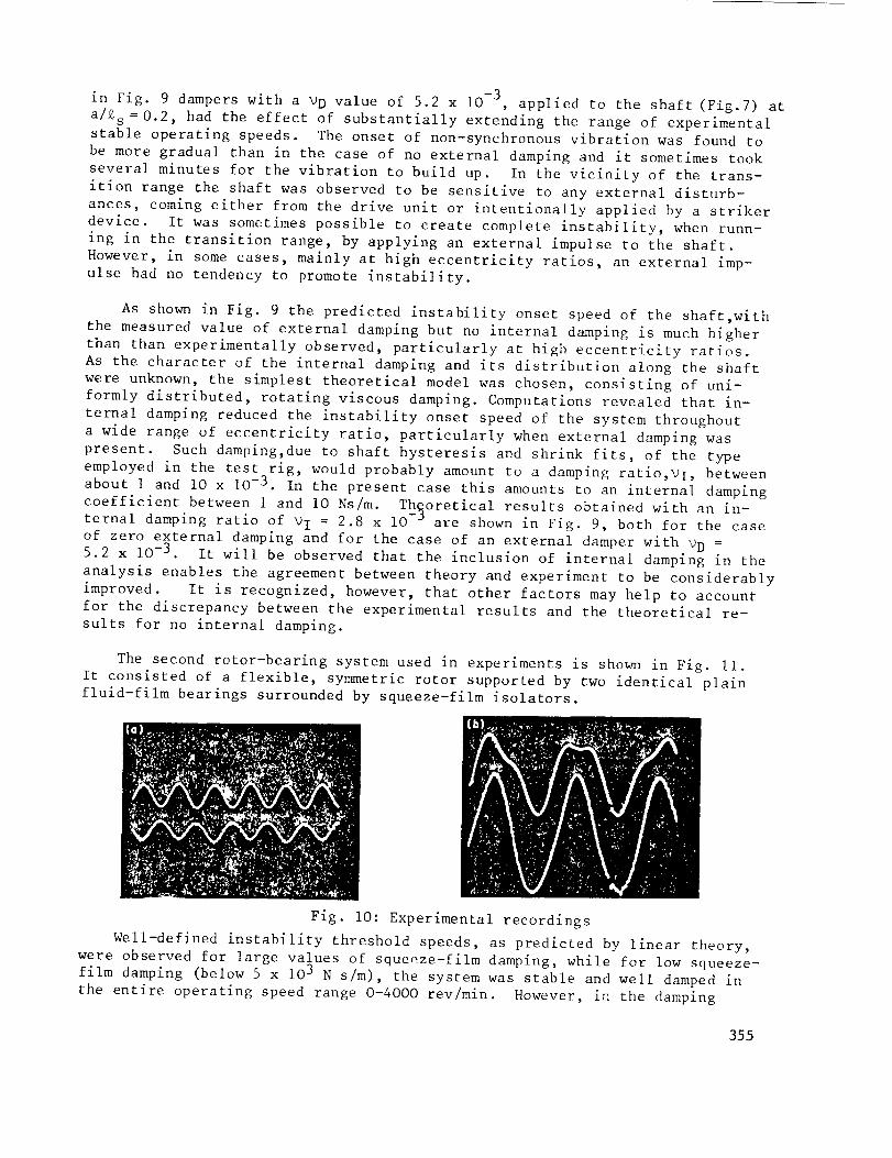
The shaft motion was measured at two locations in the horizontal plane
(quarter span and three-quarter span) which corresponded to the peaks of the
second mode shape. Fig. 10a shows the vibration at these points, for
= 3300 rev/min. When the threshold speed is reached the shaft becomes un-
stable with a precession frequency and shape corresponding to the first mode.
This is illustrated in the experimental results shown in Fig. lOb for which
the same locations have been used and _ = 3350 rev/min.
It was found experimentally that even a small amount of external damping had
a considerable stabilizing effect on the shaft. For example, as shown
354
-3in Fig. 9 dampers with a _D value of 5.2 x I0 , applied to the shaft (Fig.7) at
a/k s = 0.2, had the effect of substantially extending the range of experimental
stable operating speeds. The onset of non-synchronous vibration was found to
be more gradual than in the case of no external damping and it sometimes took
several minutes for the vibration to build up. In the vicinity of the trans-
ition range the shaft was observed to be sensitive to any external disturb-
ances, coming either from the drive unit or intentionally applied by a striker
device. It was sometimes possible to create complete instability, when runn-
ing in the transition range, by applying an external impulse to the shaft.
However, in some cases, mainly at high eccentricity ratios, an external imp-
ulse had no tendency to promote instability.
As shown in Fig. 9 the predicted instability onset speed of the shaft,with
the measured value of external damping but no internal damping is much higher
than than experimentally observed, particularly at high eccentricity ratios.
As the character of the internal damping and its distribution along the shaft
were unknown, the simplest theoretical model was chosen, consisting of uni-
formly distributed, rotating viscous damping. Computations revealed that in-
ternal damping reduced the instability onset speed of the system throughout
a wide range of eccentricity ratio, particularly when external damping was
present. Such damping,due to shaft hysteresis and shrink fits, of the type
employed in the test rig, would probably amount to a damping ratio,_l, between
about 1 and IO x 10 -3 . In the present case this amounts to an internal damping
coefficient between 1 and I0 Ns/m. Theoretical results obtained with an in-ternal damping ratio of _I = 2.8 x IO- are shown in Fig. 9, both for the case
of zero external damping and for the case of an external damper with _D =5.2 x 10 -3 . It will be observed that the inclusion of internal damping in the
analysis enables the agreement between theory and experiment to be considerably
improved. It is recognized, however, that other factors may help to account
for the discrepancy between the experimental results and the theoretical re-
sults for no internal damping.
The second rotor-bearing system used in experiments is shown in Fig. Ii.
It consisted of a flexible, symmetric rotor supported by two identical plain
fluid-film bearings surrounded by squeeze-film isolators.
Fig. IO: Experimental recordings
Well-defined instability threshold speeds, as predicted by linear theory,
were observed for large values of squeeze-film damping, while for low squeeze-
film damping (below 5 x 10³ N s/m), the system was stable and well damped in
the entire operating speed range 0-4000 rev/min. However, in the damping
355

range 6 x 10³ - 3 x 10⁴ N s/m, steady non-synchronous whirling commenced at a
rotational speed in the region of 1740-2250 rev/min, i.e. between twice and
three times the first critical speed, with the exact onset speed depending on
the damping value. The non-synchronous whirl amplitude would increase with
speed up to about 2400 rev/min, i.e. about three times the first critical
speed, whereafter the non-synchronous whirl component amplitude would decrease
rapidly and vanish at about 2400-2740 rev/min. The response would then remain
synchronous up to about 2870-3230 rev/min, still depending on the particular
squeeze-film damping value, where non-synchronous whirling would reappear. In
some instances, again depending on the damping, the whirl amplitudes at this
speed would continue to grow, indicating conventional system instability, while
in other cases the amplitude grew to a maximum with increasing speed and dis-
appeared at about 3690-3800 rev/min. Thereafter,the system would remain stable
up to and including the maximum operating speed of 4000 rev/min.
With an increase in oil temperature, it was possible to eliminate the sec-
ond non-synchronous whirl region, and a further temperature increase would re-
sult in the disappearance of the first whirl region also, making the system in-
herently stable by not allowing the journal bearing oil films to exert their
full influence. However, the system remained very sensitive to random transient
excitation, such as tapping of the foundation with a rubber hammer, particularly
near the first whirl region, and generally appeared to be very lightly damped
at all speeds above twice the first critical speed. Variations in oil supply
pressure had relatively little effect. The non-synchronous whirling exhibited
the well-known hysteresis effect of persisting over a wider speed range once
initiated.
Fig. 12 shows examples of the non-synchronous whirl orbits in the two whirl
regions. The steady-state double and triple loops indicate whirl speeds of
exactly 1/3 and 1/4 of the respective rotational speeds. Only at speeds of 2430
and 3323 rev/min (corresponding to roughly three times and four times the first
critical speed) were the orbits stationary. Non-synchronous whirling was never
found to reappear, either experimentally or theoretically, as a result of reduc-
tion in the bearing support damping from about i x 104 N s/m down to the minimum
value of about 200 N s/m. Both the _xperimental and the predicted effects of
bearing support stiffness were almost negligible within the covered stiffnessrange of 7 x 10⁵ down to 8.85 x IO N/m.
CONCLUSIONS
The main conclusions of the work described in this paper can be summarised
as follows.
I) For a rigid rotor running in uncavitated journal bearings a good qualitative
understanding of oil-whirl instability can be obtained by utilising in turn
the short and long bearing assumptions in numerical computations.
2) For a flexible rotor-bearing system it was revealed that small amounts of
external damping at a position in the shaft span increase the instability
onset speed and that this effect is most pronounced when the eccentricity
ratio for the bearings is high. External point damping is thus a useful method
356

for achieving stability control.
3) Experimental work has verified the theoretical assumption that the oil filmsin the bearings remain cavitated, even at the threshold of instability.
4) Instability onset speeds from two up to three times the first critical speedhave been achieved experimentally, by varying the bearing operating condi-tions.
5) Goodagreementbetween theoretically and experimentally determined instabi-lity onset speeds has been obtained in the case of no external point damp-ing.
6) In the case of externally applied point damping, it has been shownthat theinclusion of internal damping in the analysis enables the agreement be-tween theoretically and experimentally determined instability onset speedsto be considerably improved. Internal damping had relatively little effectwhen no external point dampingwas applied.
7) The feasibility of controlling the vibration of a rotor-bearing system bymounting the bearings on squeeze-film isolators has also been demonstrated.Both numerical predictions and experimental results showa great improve-ment in stability when suitable external damping is employed. Inherentstability could be obtained within a large range of isolator stiffnessand dampingvalues, while for other values nonlinear behaviour was observedover distinct speed ranges where subharmonic steady-state vibrations oforders up to four occurred.
2smQI2_30 3323revl rain
j 1265rr_ I
Fig. II: Experimental system
REFERENCES
Fig.12: Non-synchronous
orbits
I) Holmes, R. 'Oil whirl characteristics of a rigid rotor in 360 ° journal
bearings'., Proc. Instn Mech. Engrs. 1963, 177, (No.ll), 291.
2) Holmes, R. 'The vibration of a rigid shaft on short sleeve-bearings'
Journ. of Mech. Engng Sci._1960, _, 337-341.
3) Swift, H.W. 'Fluctuating loads in sleeve bearings' J. Instn. Civ.Engrs
1937, _, 161.
4) Capriz ,G. 'Sulle vibrazioni della aste rotanti' 1963 Ann Scuola Normale
Superiore, 17, 31.45.
357