Embed Size (px)
Citation preview

Mon. Not. R. Astron. Soc. 000, 000–000 (0000) Printed 16 July 2018 (MN LATEX style file v2.2)
On radiative acceleration in spine–sheath structured blazar jets
A. Chhotray1?, F. Nappo2,3, G. Ghisellini3, O. S. Salafia4,3, F. Tavecchio3, D. Lazzati1
1 Department of Physics, Oregon State University, 97331 Corvallis, Oregon, USA2 Dipartimento di Scienza e Alta Tecnologia, Universita degli Studi dell’Insubria, Via Valleggio 11, I–22100 Como, Italy3 INAF – Osservatorio Astronomico di Brera, Via Bianchi 46, I–23807 Merate, Italy4 Dipartimento di Fisica “G. Occhialini”, Universita degli Studi di Milano–Bicocca, P.za della Scienza 3, I–20126 Milano, Italy
16 July 2018
ABSTRACTIt has been proposed that blazar jets are structured, with a fast spine surrounded by a slowersheath or layer. This structured jet model explains some properties of their emission and mor-phology. Because of their relative motion, the radiation produced by one component is seenamplified by the other, thus enhancing the inverse Compton emission of both. Radiation isemitted anisotropically in the comoving frames, and causes the emitting plasma to recoil. Asseen in the observer frame, this corresponds to a deceleration of the fastest component (thespine) and an acceleration of the slower one (the layer). While the deceleration of the spine hasalready been investigated, here we study for the first time the acceleration of the sheath andfind self–consistent velocity profile solutions for both the spine and the sheath while account-ing for radiative cooling. We find that the sheath can be accelerated to the velocities requiredby the observations if its leptons remain energetic in the acceleration region, assumed to be ofthe order of ∼100 Schwarzschild radii, demanding continuous injection of energetic particlesin that region.
Key words: Galaxies: BL Lacertae objects: general — Radiation mechanisms: non-thermal— Relativistic processes —
1 INTRODUCTION
Relativistic jets in low-power radio–loud active galactic nuclei(AGN) are thought to be structured, namely composed of a fastcentral part, that we call the spine, and a sheath or a layer sur-rounding it, moving at a slower speed. There are several argumentsthat support the structured jet hypothesis. It is very unlikely thatthe jet plasma moves with a large bulk Lorentz factor Γ (∼ 10–15) inside the jet and with Γ = 1 just outside it. The velocity ofthe plasma should decrease gradually across the edge of the jet be-cause of shear viscosity and/or Kelvin–Helmoltz instabilities (e.g.,Henri & Pelletier 1991; for a review see Ferrari 1998; see also Bodoet al. 2003). Structured jets could also result from the accelerationmechanism itself (e.g., McKinney 2006).
Observationally, the emission of high energy γ–ray radiationrequires a large bulk Lorentz factor in blazars (i.e., sources whosejets are pointing at us), to avoid suppression by the γγ → e± pro-cess. Low-power, TeV emitting BL Lacs require the largest val-ues of Γ among all blazars (Tavecchio et al. 2001, Kino, Taka-hara & Kusunose 2002; Katarzynski, Sol & Kus 2003; Krawczyn-ski, Coppi & Aharonian 2002; Konopelko et al. 2003; Tavecchioet al., 2010). However, the Large Area Telescope (LAT) onboardthe Fermi satellite has detected (low-power) radio galaxies at ∼
? Email: [email protected]
GeV energies (Abdo et al. 2010; Grandi 2012). Their radiationcannot be the de–beamed emission coming from plasma movingwith Γ ∼ 15, since the de–beaming would be too strong, makingthe flux undetectable. The GeV radiation of radio galaxies must beproduced by material moving with Γ ∼ 3 (Ghisellini, Tavecchio &Chiaberge 2005) which is high enough to avoid the γγ absorptionprocess but sufficiently small to avoid strong de–beaming of theflux.
Detailed VLBI radio maps of Mkn 501 revealed a limb bright-ening morphology, interpreted as evidence of a slower external flowsurrounding a faster spine (Giroletti et al. 2004). Similar resultshave been obtained for Mkn 421 (Giroletti et al. 2006), 0502+675and 1722+119 (Piner & Edwards 2014).
In addition to the above evidences for structured AGN jets,there is also mounting evidence for a decelerating spine in TeVBL Lacs, and therefore radial structure. Many TeV BL Lacs arenot superluminal sources at the ∼pc scale (Edwards & Piner 2002;Piner & Edwards 2004, 2014; Piner, Pant & Edwards 2010, 2008)even though they require the highest bulk Lorentz factors in theTeV emitting region (that is in most, but not all, cases located atsub–pc distances from the black hole).
Georganopoulos & Kazanas (2003) proposed a model inwhich the jet has a fast inner part and a slower part further out.In their model, the fast base of the jet sees the radiation producedby the slower zone relativistically boosted. Analogously, the slow
c© 0000 RAS
arX
iv:1
610.
0071
7v1
[as
tro-
ph.H
E]
3 O
ct 2
016
2 A. Chhotray et al.
part of the jet sees the radiation coming from the fast base of the jetrelativistically boosted. The radiation energy density seen by bothcomponents is amplified with respect to the pure one–zone model.
Ghisellini, Tavecchio & Chiaberge (2005) proposed a “spine–layer” (or spine–sheath) jet structure with the two components hav-ing different velocities (the spine is faster). As before, each com-ponent receives increased amounts of seed photons. In this con-figuration the fast spine could be decelerated by the Comptonrocket effect (O’Dell 1981), justifying the decelerating jet modelof Georganopoulos & Kazanas (2003). The spine–layer model hasbeen successfully applied to explain the high energy emission ofradiogalaxies (M87: Tavecchio & Ghisellini 2008; NGC 1275:Tavecchio & Ghisellini, 2014; 3C 66B: Tavecchio & Ghisellini2009) and slightly misaligned blazars (PKS 0521–36: D’Ammandoet al. 2015). It has also been shown to help the production of highenergy neutrinos in the relativistic jet of radio–sources (Tavecchio,Ghisellini & Guetta 2014).
In the original model and in the later application to specificsources, the velocity of the layer was a free parameter, and wasassumed to be constant. On the other hand, the emitting plasmaof the layer, being illuminated by the photons of the spine, emitsanisotropically in its comoving frame and thus must recoil. Therelative bulk Lorentz factor between the two structures is thereforebound to decrease, limiting the seed amplification effect leading tothe extra inverse Compton emission.
In the initial jet zone (where there is no radiative interplay be-tween the spine and the layer), the jet launching mechanism coulditself be responsible for accelerating both the spine and the layer(e.g. McKinney 2006). An alternative option is that this launchingmechanism is responsible only for the acceleration of the spine,while the layer gets accelerated radiatively. The aim of this paper isto study self-consistently the photon-mediated interaction betweenthe two jet components that move with high relative velocity andthus find out which of the two options is preferred. In particular,we aim to explore and describe the dynamic coupling of the two ra-dial components and to better understand this physical feedbackprocess, as it could be important for relativistic jets in general,including Gamma Ray Bursts (e.g., Rossi et al. 2002; Lazzati &Begelman 2005).
This paper is organized as follows: in § 2 we discuss the setupof the model and the assumption made to make it mathematicallytractable. In § 3 we present and discuss our results, and this is fol-lowed by our conclusions in § 4. We divide the study in five parts: i)we find the velocity profile of the layer assuming a constant spinevelocity, and assuming a fixed energy distribution of the emittingelectrons in the spine–layer system; ii) we study the layer motionassuming that the emitting electrons are injected at the start, andthen radiatively cool; iii) we explore the layer’s motion for a casewhere the injected electrons maintain a fixed energy distribution in-side a fixed volume (this fixed volume is discussed in greater detailin § 2.1) and cool radiatively once the plasma exits that volume; iv)we self–consistently calculate the motion of the spine and the layer,under their reciprocal radiative influence; and v) we study how theself–consistent motion of the spine–layer system is influenced byelectron–positron pair loading.
2 SET UP OF THE MODEL
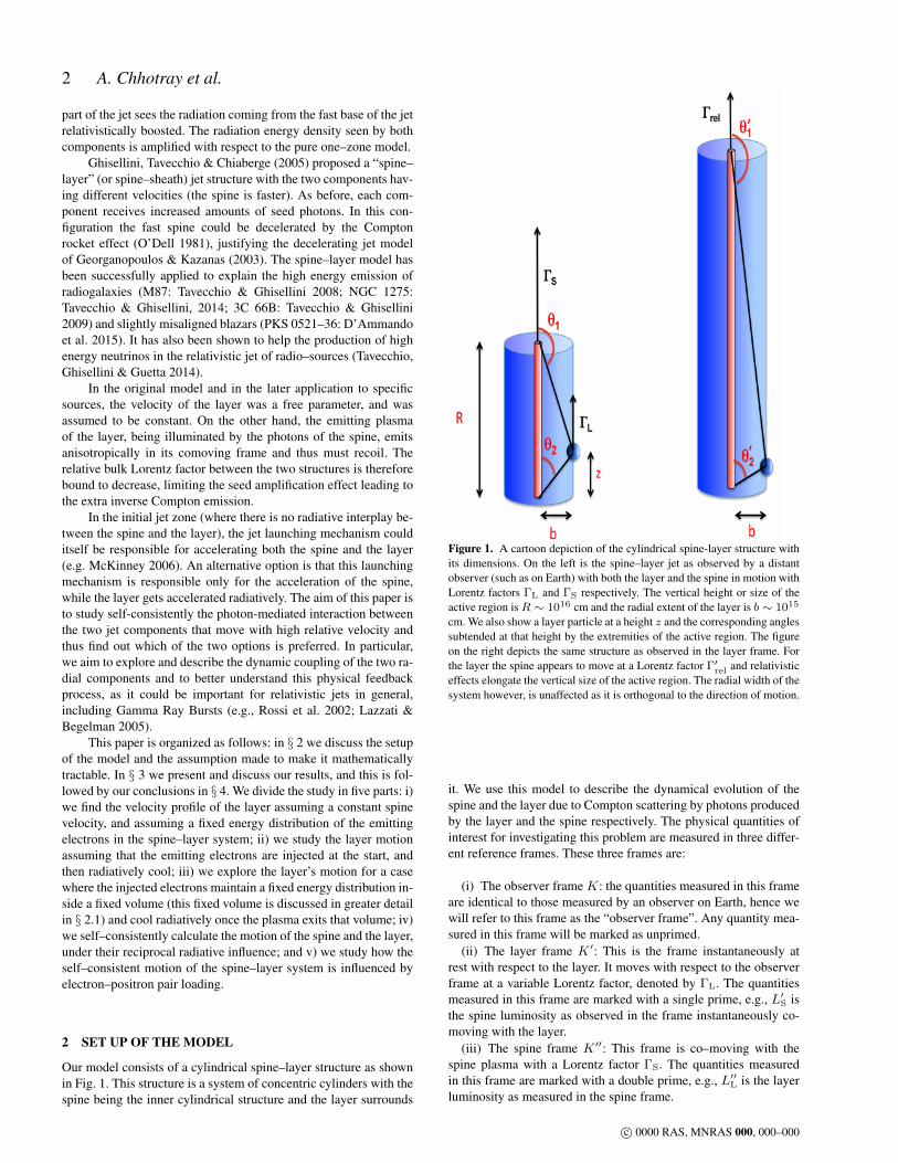
Our model consists of a cylindrical spine–layer structure as shownin Fig. 1. This structure is a system of concentric cylinders with thespine being the inner cylindrical structure and the layer surrounds
Figure 1. A cartoon depiction of the cylindrical spine-layer structure withits dimensions. On the left is the spine–layer jet as observed by a distantobserver (such as on Earth) with both the layer and the spine in motion withLorentz factors ΓL and ΓS respectively. The vertical height or size of theactive region isR ∼ 1016 cm and the radial extent of the layer is b ∼ 1015
cm. We also show a layer particle at a height z and the corresponding anglessubtended at that height by the extremities of the active region. The figureon the right depicts the same structure as observed in the layer frame. Forthe layer the spine appears to move at a Lorentz factor Γ′rel and relativisticeffects elongate the vertical size of the active region. The radial width of thesystem however, is unaffected as it is orthogonal to the direction of motion.
it. We use this model to describe the dynamical evolution of thespine and the layer due to Compton scattering by photons producedby the layer and the spine respectively. The physical quantities ofinterest for investigating this problem are measured in three differ-ent reference frames. These three frames are:
(i) The observer frame K: the quantities measured in this frameare identical to those measured by an observer on Earth, hence wewill refer to this frame as the “observer frame”. Any quantity mea-sured in this frame will be marked as unprimed.
(ii) The layer frame K′: This is the frame instantaneously atrest with respect to the layer. It moves with respect to the observerframe at a variable Lorentz factor, denoted by ΓL. The quantitiesmeasured in this frame are marked with a single prime, e.g., L′S isthe spine luminosity as observed in the frame instantaneously co-moving with the layer.
(iii) The spine frame K′′: This frame is co–moving with thespine plasma with a Lorentz factor ΓS. The quantities measuredin this frame are marked with a double prime, e.g., L′′L is the layerluminosity as measured in the spine frame.
c© 0000 RAS, MNRAS 000, 000–000
Radiative acceleration in spine–sheath blazar jets 3
2.1 Assumptions
We simplify the analysis of our spine–layer model by assuming thatthe spine is uni–dimensional and is in motion with an initial Lorentzfactor ΓS,0 (measured in the observer frame) along the jet–axis di-rection (referred to as z–axis) as is depicted in the left panel of Fig.1 by the inner cylinder. The layer is the outer cylinder surroundingthe spine, has a radius of b ∼ 1015 cm and, like the spine, travelsalong the jet axis with an initial Lorentz factor given by ΓL,0 (sub-script L denotes layer which we shall use synonymously with thesheath).
In our model we assume that the both the spine and the layerare ‘active’ only between two points which are fixed in the observerframe and separated by a distance of R = 1016 cm, implying theemitting volume to be fixed in that frame. Such an active regioncan be a result of a standing shock, where energy dissipation hap-pens between fixed points. Both the spine and the sheath emit radia-tion isotropically in their respective reference frames, however anyother frame would observe the emissions to be beamed. We thusintroduce the relativistic Doppler factor (hereafter beaming factor)δ as:
δL =1
ΓL(1− βL cos θ)(1)
which is the beaming factor of the radiation produced in the layerframe as seen in the observer frame. θ is the angle between the jetaxis and the line of sight as measured in the observer frame.
δS =1
ΓS(1− βS cos θ)(2)
is the beaming factor of the radiation produced in the spine frameas seen in the observer frame, and
δS,L =δSδL
(3)
is the relative beaming factor of the radiation produced in the spineframe and as seen in the layer frame (see also Georganopoulos &Kazanas 2003; Ghisellini et al. 2005).
The forces resulting from Compton scattering of the layer par-ticles by the spine photons can drive/accelerate the sheath (in thiswork we consider scattering only within the Thomson regime). Asthe seed photons of Compton scattering are produced outside thelayer, if the scattering particles are hot in K′, the scattered radia-tion is anisotropic also in the layer co–moving frame, making thelayer recoil. For this reason, this interaction is often called Comp-ton Rocket (Sikora et al., 1996; Ghisellini & Tavecchio, 2010; Vuil-laume, Henri & Petrucci, 2015) and for hotter particles this drivingforce increases proportionally to their average internal energy 〈γ2〉.
We assume that the layer particle is free to move in the di-rection parallel to the jet axis. For simplicity, we assume that thedistance between the layer and the jet axis, b, is fixed, despite thepresence of a radial radiative force, and thus also along the nor-mal to the jet axis. This can be achieved through the presence ofa magnetic field. To analyze the motion of the sheath we consideran infinitesimal part of the sheath at a position z which we treat asan “effective particle”. The constituent particles inside the layer arerepresentative of the sheath particles and the sheath can be thoughtof as composed of a collection of these effective particles (see also§2.3).
The right panel of Fig. 1 depicts the structure as viewed in theframe of the sheath. The sheath finds the spine moving at a Lorentzfactor Γrel = ΓSΓL(1 − βSβL) and due to the aberration of lightobserves the vertical dimension of the active region to be larger
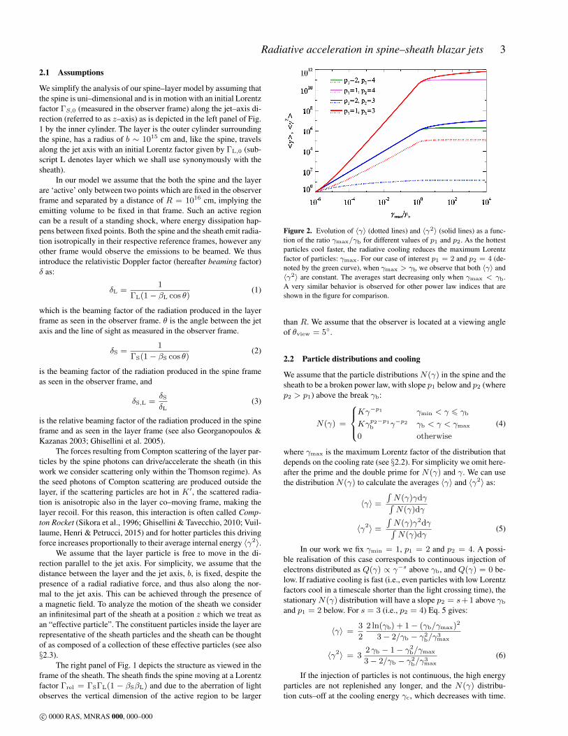
Figure 2. Evolution of 〈γ〉 (dotted lines) and 〈γ2〉 (solid lines) as a func-tion of the ratio γmax/γb for different values of p1 and p2. As the hottestparticles cool faster, the radiative cooling reduces the maximum Lorentzfactor of particles: γmax. For our case of interest p1 = 2 and p2 = 4 (de-noted by the green curve), when γmax > γb we observe that both 〈γ〉 and〈γ2〉 are constant. The averages start decreasing only when γmax < γb.A very similar behavior is observed for other power law indices that areshown in the figure for comparison.
than R. We assume that the observer is located at a viewing angleof θview = 5.
2.2 Particle distributions and cooling
We assume that the particle distributions N(γ) in the spine and thesheath to be a broken power law, with slope p1 below and p2 (wherep2 > p1) above the break γb:
N(γ) =
Kγ−p1 γmin < γ 6 γb
Kγp2−p1b γ−p2 γb < γ < γmax
0 otherwise
(4)
where γmax is the maximum Lorentz factor of the distribution thatdepends on the cooling rate (see §2.2). For simplicity we omit here-after the prime and the double prime for N(γ) and γ. We can usethe distribution N(γ) to calculate the averages 〈γ〉 and 〈γ2〉 as:
〈γ〉 =
∫N(γ)γdγ∫N(γ)dγ
〈γ2〉 =
∫N(γ)γ2dγ∫N(γ)dγ
(5)
In our work we fix γmin = 1, p1 = 2 and p2 = 4. A possi-ble realisation of this case corresponds to continuous injection ofelectrons distributed as Q(γ) ∝ γ−s above γb, and Q(γ) = 0 be-low. If radiative cooling is fast (i.e., even particles with low Lorentzfactors cool in a timescale shorter than the light crossing time), thestationaryN(γ) distribution will have a slope p2 = s+1 above γb
and p1 = 2 below. For s = 3 (i.e., p2 = 4) Eq. 5 gives:
〈γ〉 =3
2
2 ln(γb) + 1− (γb/γmax)2
3− 2/γb − γ2b/γ
3max
〈γ2〉 = 32 γb − 1− γ2
b/γmax
3− 2/γb − γ2b/γ
3max
(6)
If the injection of particles is not continuous, the high energyparticles are not replenished any longer, and the N(γ) distribu-tion cuts–off at the cooling energy γc, which decreases with time.
c© 0000 RAS, MNRAS 000, 000–000

4 A. Chhotray et al.
The cooling of the plasma impacts the particle energy distributionwhich in turn affects the force that these particles experience (seeEq. 9). Therefore we have to account for radiative cooling of thesheath/spine plasma due to irradiation by the spine/sheath photons.The cooling rate is (e.g. Rybicki & Lightman 1979):
γ =dγ
dt′=
4
3
σTcU′γ2
maxβ2max
mec2(7)
where U ′ is the integrated radiation energy density in the layerframe, γmax and βmax are respectively the Lorentz factor and speedof the particle possessing the maximum internal energy (hence thesubscript max) in a hot plasma. At each timestep ∆t′i we calculatethe cooling Lorentz factor of the leptons using Eq. 7:
γc,i = γmax,i−1 − γi−1∆t′i
= γmax,i−1 −4
3
σTcU′i−1γ
2max,i−1β
2max,i−1
mec2∆t′i (8)
We assume that the particle distribution vanishes for γ > γc: thecooling Lorentz factor γc becomes the new maximum Lorentz fac-tor of the distribution, i.e., γmax,i+1 = γc,i. Since γc is time de-pendent, the averages 〈γ〉 and 〈γ2〉 (see eqs. 6) also become timedependent. Graphically, the evolution of the averages as a functionof the ratio γmax/γb (in other words, with time due to cooling) isdepicted in the Fig. 2 for several power-law indices.
2.3 The equation of motion
In order to study the trajectory of the sheath or the layer, we requirethe equation of motion given as
dp
dt= F ′ (9)
where dp and dt are calculated in the same frame (any frame), butF ′ is calculated in the frame comoving with the particle (see e.g.Weinberg, 1972). Since we assume that the layer and the spine areoptically thin, we can calculate the motion of a single particle due toCompton scattering. We define f as the ratio of number of leptonsto protons and f > 1 indicates the presence of pairs in the plasma.This enables us to study the motion of an “effective particle” ofinertial massmi = mp/f + 〈γ〉me, where the electron massme ismultiplied by 〈γ〉 to account for the average internal energy of theleptons. Equation 9 can be written as:
micd(Γβ)
dt= F ′ (10)
We begin by considering the motion of the layer due to the interac-tion with the radiation produced by the spine (moving with a con-stant bulk Lorentz factor ΓS). In this case, the driving force F ′z(z)can be computed by considering the flux received by a particle inthe layer located at a given z. This flux will be produced at dif-ferent heights of the spine, seen under a different angle and witha different beaming. Therefore we will have to integrate over theentire length of the spine while accounting for the different degreesof relativistic effects.From the detailed calculations as shown in the appendix, we writethe equation of motion (Eq. 10) as:
d(ΓLβL)
dt=
16
9
σT
mibc2〈γ2〉η
∫ θ2
θ1
λ′′Sδ4S
δ2L
cos θ − βL
1− βL cos θdθ (11)
where η is a factor of the order of unity that depends on the geom-
etry of the system (in this case we used η = 2/π), λ′′S =dL′′Sdx′′
isthe spine comoving linear luminosity density which is connected tothe spine isotropic luminosity Liso,S.
2.3.1 The drag Lorentz factor
This section introduces the physical meaning of drag Lorentz fac-tor ΓL,drag which we will frequently use to understand our results.ΓL,drag is the value of ΓL for which the z component of the force asmeasured in the comoving layer frame vanishes. The net force act-ing on the effective layer particle at a certain position is computedby accounting for photons that hit the effective particle both fromabove and below its position. As seen in the observer frame K,photons that hit the sheath “effective particle” with an incident an-gle less than 1/ΓL with respect to the sheath’s direction of motionappear to arrive from above the effective particle’s position in thesheath comoving frame. These photons decelerate the particle byimparting negative momentum (negative force). On the other hand,photons that are incident with an angle greater than 1/ΓL will ac-celerate the particle, generating a positive force. The value of thelayer Lorentz factor for which these positive and negative forcesare equal is called the drag Lorentz factor. Its value as a function ofz can be obtained by imposing the condition that F ′z = 0, and thissimplifies Eq. 11 to:∫ θ2
θ1
δ4SΓ2
L,drag(1− βL,drag cos θ)(cos θ− βL,drag)dθ = 0 (12)
Since the sign of the total force F ′z depends only on the sign of theintegral in Eq. 11 or Eq. 12, we will have:
F ′z > 0 if ΓL < ΓL,drag
F ′z < 0 if ΓL > ΓL,drag
F ′z = 0 if ΓL = ΓL,drag
2.4 Feedback
The previous subsections describe the dynamical evolution of thesheath plasma interacting via Compton scattering with the spinephotons. However, we ignored the effect of the sheath photons onthe spine to simplify the analysis. In this section, we relax thatassumption by accounting for the interaction of the layer photonswith the spine and how this interaction modifies the spine Lorentzfactor ΓS(z). As a result, we can explore how the feedback betweenthe spine–layer structure self regulates its very own dynamical evo-lution.To study the spine–layer feedback, we need to modify some equa-tions of the previous section according to the following considera-tions:
• As the bulk Lorentz factors for both the spine and the layercan be modified, we must compute two profiles ΓS(z) and ΓL(z)for the spine and the layer respectively.• The linear luminosity density profiles of the spine and the
layer (λS and λL) can vary with position, but we assume that thecomoving luminosity density profiles are proportional to the aver-age square of the particle energies constituting the emitting plasma,i.e., λ′′S ∝ 〈γ2
S〉 and λ′L ∝ 〈γ2L〉. Thus, if the internal energy content
of the plasma changes by radiative cooling, the comoving luminos-ity profile will no longer be independent of the position.• We take advantage of the symmetry of the problem and sup-
pose that the effect of the spine on the layer and the inverse effect,i.e., of the layer on the spine can be expressed by the same relationsby simply switching the subscripts.
These considerations lead to the following system of differ-ential equations describing the evolution of two “effective parti-cles” that represent the spine and the layer (having masses mS =
c© 0000 RAS, MNRAS 000, 000–000

Radiative acceleration in spine–sheath blazar jets 5
mp/fS + 〈γS〉me and mL = mp/fL + 〈γL〉me for the spine andthe layer respectively):mSc
d(ΓSβS)
dt=
16
9
σT
bc〈γ2
S〉η∫ θ2
θ1
λ′L(θ)δ4L
δ2S
cos θ − βS
1− βS cos θdθ
mLcd(ΓLβL)
dt=
16
9
σT
bc〈γ2
L〉η∫ θ2
θ1
λ′′S(θ)δ4S
δ2L
cos θ − βL
1− βL cos θdθ
(13)All the important steps leading to the above equations are fully de-scribed in the Appendix, along with the limits of integrations θ1, θ2
(which can be obtained using the Eqs. A13 and A14 respectively).We can compute the Lorentz factor profiles ΓS(z) and ΓL(z) bynumerically solving this system. The reader should note that theacceleration of the layer (spine) depends linearly on the product ofthe isotropic luminosity of the spine (layer) and the average of thesquare of the leptonic Lorentz factor of the layer (spine). We callthis product k:
kS = Liso,L · 〈γ2S〉; kL = Liso,S · 〈γ2
L〉 (14)
Hence we treat this product as a single parameter.
3 RESULTS AND DISCUSSION
In this section we present and discuss the results of the numericalintegration of the equations of motion considering different condi-tions:
• §3.1: Radiative acceleration of the layer: No cooling scenario• §3.2: Radiative acceleration of the layer: Cooling scenario
– §3.2.1: Single injection– §3.2.2: Continuous injection
• §3.3: The spine–layer feedback
– §3.3.1: Continuous injection with feedback
• §3.4: The spine–layer feedback in e+e− pair loaded plasmas
3.1 Radiative acceleration of the layer: No cooling scenario
In this section we start with the simplest and somewhat unrealisticscenario where:
i) the spine moves with a constant bulk Lorentz factor ΓS (notconsidering its deceleration due to layer photons);
ii) the sheath particle distribution does not change with time (i.e.,the particles do not cool by radiative emission, or the cooling isexactly compensated by injection of new particles).
By switching ’off’ the cooling we have made this scenario some-what unrealistic, but this simplifies the problem at hand and in turnallows us to gain greater insight and develop intuition about theradiative acceleration phenomena. This will help to improve ourunderstanding of more complex scenarios discussed later in the pa-per. We solve the equation of motion of the layer under differentconditions (however we only vary a single parameter in each caseto develop intuition) and we show the spatial profiles of (Γβ)L andof the force perceived by the layer projected over the z–axis F ′z(z).
Varying kL — Fig. 3 shows the effects of varying kL for aconstant spine Lorentz factor ΓS = 15 and an initial bulk Lorentzfactor of the layer ΓL,0 = 3. At the base of the structure, i.e.,for small values of z, the forces are negative for all the curvesirrespective of the kL value (the yellow curve has the greatest
Figure 3. Radiative acceleration of the layer by varying kL = Liso,S ·〈γ2L〉
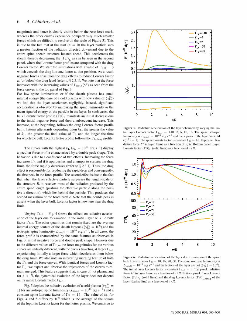
(values from 1045 to 1051 erg s−1). The spine Lorentz factor is constantΓS = 15. The initial Lorentz factor of the layer is ΓL,0 = 3. The x–axisis common for the two panels and depicts the position z normalized by thevertical structure dimension R. Top panel: radiative force F ′ as measuredin the frame of the layer as a function of z/R. Bottom panel: layer Lorentzfactor (Γβ)L (solid lines) and the drag Lorentz factor (Γβ)L,drag of thelayer (dashed line) as a function of z/R.
Figure 4. Radiative acceleration of the layer obtained by varying the ini-tial layer Lorentz factor ΓL,0 = 1.01, 3, 5, 10, 15. The spine isotropicluminosity is Liso,S = 1045 erg/s and the leptons of the layer are hot(〈γ2
L〉 = 106) implying kL = 1051 erg/s. The spine Lorentz factor isconstant ΓS = 15. Top panel: radiative force F ′ in layer frame as a func-tion of z/R. Bottom panel: layer Lorentz factor (Γβ)L (solid lines) and thedrag Lorentz factor (Γβ)L,drag of the layer (dashed line) as a function ofz/R; Inset: a zoomed view of the behaviour of the layer Lorentz factor for0 < z/R < 1.
c© 0000 RAS, MNRAS 000, 000–000
6 A. Chhotray et al.
magnitude and hence is clearly visible below the zero force mark,whereas the other curves experience comparatively much smallerforces which are difficult to resolve on the scale of Figure 3). Thisis due to the fact that at the start (z = 0) the layer particle seesa greater fraction of the radiation directed downward due to theentire spine–sheath structure located ahead. This decelerates thesheath thereby decreasing the (Γβ)L as can be seen in the secondpanel, where the Lorentz factor profiles are compared with the dragLorentz factor. We start the simulations with a value of ΓL,0 = 3which exceeds the drag Lorentz factor at that position. As a resultnegative forces arise from the drag effects to reduce Lorentz factorat (or below) the drag level (refer to § 2.3.1). We note that the forceincreases with the increasing values of Liso,S〈γ2〉 as seen from theforce curves in the top panel of Fig. 3.For low spine luminosities or if the sheath plasma has smallinternal energy (the case of a cold plasma with low value of 〈γ2
L〉)we find that the layer accelerates negligibly. Instead, significantacceleration is observed by increasing the spine luminosity or themean squared energy of the particle in the layer. In such cases, thebulk Lorentz factor profile (Γβ)L manifests an initial decrease dueto the initial negative force and then a subsequent increase. Thisincrease, at the beginning, follows the drag Lorentz factor profilebut it flattens afterwards depending upon kL: the greater the valueof kL, the greater the final value of ΓL and the longer the timefor which the bulk Lorentz factor profile follows the ΓL,drag profile.
The curves with the highest kL (kL = 1051 erg s−1) displaya peculiar force profile characterized by a double peak shape. Thisbehavior is due to a confluence of two effects. Increasing the forceincreases ΓL and if it approaches and attempts to surpass the draglimit, the force rapidly decreases (refer to § 2.3.1). Thus, the drageffect is responsible for producing the rapid drop and consequently,the first peak in the force profile. The second effect is due to the factthat when the layer effective particle surpasses the length–scale ofthe structure R, it receives most of the radiation produced by theentire spine length (pushing the effective particle along the posi-tive z direction), which lies behind the particle. This produces thesecond maximum of the force profile. Note that the double peak isabsent when the layer bulk Lorentz factor is nowhere near the draglimit.
Varying ΓL,0 — Fig. 4 shows the effects on radiative acceler-ation of the layer due to variation in the initial layer bulk Lorentzfactor ΓL,0. The other quantities that remain fixed are the averageinternal energy content of the sheath leptons (〈γ2
L〉 = 106) and theisotropic spine luminosity Liso,S = 1045 erg s−1. In all cases, theforce profile is characterized by the same features as observed inFig. 3: initial negative force and double peak shape. However dueto the different values of ΓL,0, the force magnitudes for the variouscurves are initially different, with the curves traveling at larger ΓL,0
experiencing initially a larger force which decelerates them belowthe drag limit. We also note an interesting merging feature of boththe ΓL and the force curves. With identical forces and Lorentz fac-tor ΓL, we expect and observe the trajectories of the curves to re-main merged. This feature suggests that, in case of hot plasma andfor z > R, the dynamical evolution of the layer does not dependon its initial Lorentz factor ΓL,0.
Fig. 5 depicts the radiative evolution of a cold plasma (〈γ2L〉 =
1) for an isotropic spine luminosity (Liso,S = 1045 erg s−1) and aconstant spine Lorentz factor of ΓS = 15 . The value of kL forFigs. 4 and 5 differs by 106 which is the average of the squareof the leptonic Lorentz factor for the hotter plasma. We continue to
Figure 5. Radiative acceleration of the layer obtained by varying the ini-tial layer Lorentz factor ΓL,0 = 1.01, 3, 5, 10, 15. The spine isotropicluminosity is Liso,S = 1045 erg s−1 and the leptons of the layer are cold(〈γ2
L〉 = 1). The spine Lorentz factor is constant ΓS = 15. Top panel: Ra-diative force F ′ in layer frame as a function of z/R. Bottom panel: LayerLorentz factor (Γβ)L (solid lines) as a function of z/R.
Figure 6. Radiative acceleration of the layer due to variation of the spinebulk Lorentz factor ΓS = 10, 15, 20, 50. The spine isotropic luminosity isLiso,S = 1045 erg s−1 and the leptons of the layer are hot (〈γ2
L〉 = 106).The initial layer Lorentz factor is constant ΓL,0 = 3. Top panel: radiativeforce F ′ in layer frame as a function of z/R. Bottom panel: Layer Lorentzfactor (Γβ)L (solid lines) and the drag Lorentz factor (Γβ)L,drag of thelayer (dashed line) as a function of z/R.
c© 0000 RAS, MNRAS 000, 000–000
Radiative acceleration in spine–sheath blazar jets 7
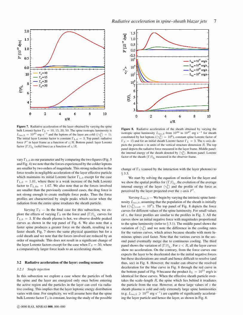
Figure 7. Radiative acceleration of the layer obtained by varying the spinebulk Lorentz factor ΓS = 10, 15, 20, 50. The spine isotropic luminosity isLiso,S = 1045 erg s−1 and the leptons of the layer are cold (〈γ2
L〉 = 1).The initial layer Lorentz factor is constant ΓL,0 = 3. Top panel: radiativeforce F ′ in layer frame as a function of z/R. Bottom panel: layer Lorentzfactor (Γβ)L (solid lines) as a function of z/R.
vary ΓL,0 as our parameter and by comparing the two figures (Fig. 5and Fig. 4) we note that the forces experienced by the colder leptonsare smaller by two orders of magnitude. This strong reduction in theforce results in negligible acceleration of the layer effective particlewhich maintains its initial Lorentz factor ΓL,0 except for the caseΓL,0 = 1.01, where there is a weak increase of the bulk Lorentzfactor to ΓL,fin = 1.67. We also note that as the forces involvedare smaller than the previously considered cases, the drag force isnot strong enough to create multiple force peaks. Thus the forceprofiles are characterized by single peaks which occur when theradiation from the entire spine irradiates the sheath particle.
Varying ΓS — In the final case for this subsection, we ex-plore the effects of varying ΓS on the force and (Γβ)L curves forΓL,0 = 3. If the sheath plasma is hot, we observe double peakedcurves as shown in the top panel of Fig. 6. We also note that afaster spine produces a greater force on the sheath, resulting in afaster sheath. Fig. 7 shows the same physical quantities but for acold sheath and we note that the forces involved are reduced by anorder of magnitude. This does not result in a significant change ofthe layer Lorentz factors except for the case when ΓS = 50, wherea comparatively larger force leads to an accelerating sheath.
3.2 Radiative acceleration of the layer: cooling scenario
3.2.1 Single injection
In this subsection we explore a case where the particles of boththe spine and the layer are energized only once before enteringthe active region and the particles in the layer can cool via radia-tive cooling. This implies that the layer leptonic energy distributionvaries with time. For simplicity, we will assume here that the spinebulk Lorentz factor ΓS is constant, leaving the study of the possible
Figure 8. Radiative acceleration of the sheath obtained by varying theisotropic spine luminosity Liso,S from 1044 to 1047 erg s−1 for sheathconstituted by hot leptons (〈γ2
L〉 = 106), constant spine Lorentz factor ofΓS = 15 and for an initial sheath Lorentz factor ΓL = 3. The x–axis de-picts the position z in units of the vertical structure dimension R. The toppanel depicts the radiative force measured in the layer frame. Middle panel:the internal energy of the sheath denoted by 〈γ2
L〉. Bottom panel: Lorentzfactor of the sheath (Γβ)L measured in the observer frame.
change of ΓS (caused by the interaction with the layer photons) to§ 3.3.
We start by solving the equation of motion for the layer andwe show the spatial profiles for (Γβ)L, the evolution of the averageinternal energy of the layer 〈γ2
L〉 and the profile of the force asperceived by the layer projected over the z-axis F ′.
VaryingLiso,S — We begin by varying the intrinsic spine lumi-nosity Liso,S, assuming that the population of the sheath is initiallyhot (〈γ2
L〉z=0 = 106). The top panel of Fig. 8 depicts the forcecurves for different values of the spine luminosity. For small valuesof z, the force profiles are similar to the profiles in Fig. 3. All thecurves show an initial negative force with magnitudes proportionalto the spine luminosity (refer to § 3.1). The middle panel shows thevariation of 〈γ2
L〉 and we note the difference in the cooling ratesfor the various curves, which arises because sheaths with more lu-minous spines cool faster. Note that the various curves in the sec-ond panel eventually merge due to continuous cooling. The thirdpanel shows the variation of (Γβ)L. For z < R, all the layer curvesshow no acceleration. On the contrary, from the force curves oneexpects the layer to be decelerated due to the initial negative forcesbut these decelerations are small and hence difficult to resolve (andthus, see) in Fig. 8. However, the reader can observe the resolveddeceleration for the blue curve in Fig. 8 through the red curve inthe bottom panel of Fig. 9 because the product kL = 1051 erg/s isidentical for these curves. When the effective sheath particle over-takes the scale–length R, the spine which lies behind it irradiatesthe particle from the rear. However, at these large values of z thesheath plasma is cold and only extremely large spine luminosities(e.g. Liso,S > 1045 erg s−1) are capable of significantly accelerat-ing the layer particle and hence the layer, as shown in Fig. 8.
c© 0000 RAS, MNRAS 000, 000–000

8 A. Chhotray et al.
Figure 9. Radiative acceleration of the sheath due to variation of the aver-age internal energy content of the sheath 〈γ2
L〉 from 1 to 106 for a constantisotropic spine luminosityLiso,S = 1045 erg s−1, a constant spine Lorentzfactor ΓS = 15 and for an initial sheath Lorentz factor ΓL = 3. The x–axis depicts the position z normalized by the vertical structure dimensionR. Top panel depicts the radiative force measured in the layer frame. Mid-dle panel: the internal energy of the sheath denoted by 〈γ2〉. Bottom panel:Lorentz factor of the sheath (Γβ)L measured in the observer frame.
Figure 10. Same as Fig. 9, but zooming out to longer z/R to see the finalvalues of (Γβ)L.
Varying 〈γ2L〉z=0 — We explore how the sheath evolves for
different initial 〈γ2L〉z=0 (in short, 〈γ2
0〉) values under the influenceof radiative cooling with an initial sheath Lorentz factor ΓL,0 = 3and a constant spine luminosity Liso,S = 1045 erg s−1. Fig. 9confirms that the force profile is characterized by negative valuesduring the initial stages, with the hottest sheaths experiencing thegreatest force magnitudes. The middle panel depicts the variation in〈γ2
L〉 due to radiative cooling. The curves show an initial flat evolu-tion and then a decreasing trend in such a manner that all the curvesmerge, irrespective of their 〈γ2
0〉 values. This behavior can be un-derstood from Fig. 2 or from particle energy distribution N(γ) ofthe layer (see Eq. 4): if the cooling energy γc is greater than thespectral break energy γb (i.e., γc > γb), then 〈γ2〉 ∼ γb whichimplies that 〈γ2〉 is almost constant (this corresponds to the ini-tially flat evolutionary phase seen in the middle panel of Fig. 9).However, when γc crosses γb, 〈γ2〉 starts to decrease from its ini-tial value and becomes comparable to γc. Note that even thoughthe force curves have merged (simultaneously with the merging of〈γ2〉 curves), the (Γβ)L curves remain segregated due to the differ-ent initial decelerations resulting from the different initial behaviorof 〈γ2〉. This leads to the interesting result – the bulk Lorentz fac-tor at saturation is maximum for an intermediate value of the initial〈γ2
L〉 (〈γ2L〉 = 104), instead of the curve with the initially hottest
leptons (〈γ2L〉 = 106), albeit by a small amount (see Fig. 10).
As a whole, we conclude from this section that the radiativecooling process causes the layer to lose internal energy rapidlyand so it quenches the process of radiative acceleration. Exceptfor cases with very high spine luminosity, we can affirm that thefinal bulk Lorentz factor of the layer ΓL does not change signifi-cantly from its initial value ΓL,0 (see Fig. 10). This result is similarto those obtained by studying the radiative acceleration of a coldplasma in the no cooling scenario (cfr. §3.1).
3.2.2 Continuous injection
This scenario explores the situation where we have continuousenergy injection inside the sheath region via, e.g., a standingshock, namely when the cooling is balanced by injection of freshenergetic particles that energize the plasma and the electronenergy distribution is assumed to stay constant between z = 0and z = 1016 cm. There is no energy injection outside the activeregion. We assume that the injection rate within the active regionis such that its effect is equivalent to making cooling ineffective.We still neglect here the radiative effects on the spine due to thelayer and hence the bulk Lorentz factor of the spine ΓS is assumedto be constant.
Differently from most of the other cases presented in thiswork, for this case we assume that the initial bulk Lorentz factorof the layer is close to unity. In fact we intent to explore if the layercan be accelerated radiatively and, achieve a bulk Lorentz factorΓL ∼ 3 as required by observations.
Fig. 11 depicts the evolution of the force, 〈γ2〉 and (Γβ)L
curves. The continuous shocking re-energizes the particles withinthe standing shock region, and it is responsible for large forcesproportional to the plasma’s internal energy 〈γ2
L〉 content. Becausethere is continuous energy injection for z 6 1016 cm, we expectthe physical quantities in this region to evolve in a fashion similarto the same quantities in § 3.1. Indeed, the evolution of the forcecurves in the standing shock region as depicted in Fig. 11 is verysimilar to Fig. 3 (the yellow curves are almost identical for z < R).The drop in the force is due to the bulk Lorentz factor of the layer
c© 0000 RAS, MNRAS 000, 000–000

Radiative acceleration in spine–sheath blazar jets 9
Figure 11. Radiative acceleration of the sheath obtained by varying theinitial average internal energy content of the sheath 〈γ2
0〉 from 102 to 106
for a constant isotropic spine luminosity Liso,S = 1045 erg s−1, a con-stant spine Lorentz factor ΓS = 15 and for an initial sheath Lorentz fac-tor ΓL,0 = 1.01. In this scenario, the plasma cools radiatively only forz/R > 1; for 0 < z/R < 1 the plasma is continuously energized andmaintains the average internal energy (thereby making cooling ineffective).The top panel depicts the radiative force measured in the layer frame. Mid-dle panel: The variation in the internal energy of the sheath denoted by 〈γ2
L〉as a function of the vertical position z. Bottom panel: (Γβ)L profile of thesheath as measured in the observer frame.
approaching ΓL,drag as explained earlier in § 3.1. All the threecurves experience positive forces, leading to an accelerated layeras demonstrated by the (Γβ)L plot in the bottom panel of Fig. 11.The cooling becomes effective for z > 1016 cm (z/R > 1), re-sulting in a rapid decrease in the values of 〈γ2
L〉 for the variouscurves (middle panel of Fig. 11). A decrease in 〈γ2
L〉 correspond-ingly produces a rapid decrease in the force values also (top panelof Fig. 11). The role of radiative cooling in quenching the radiativeforce has been explored in detail in § 3.2.1. As the force values forz > 1016 cm are quite small, we note that the layer Lorentz factorssaturate close to the values attained at z ∼ R = 1016 cm.
Fig. 11 shows that if the layer is kept hot by a mechanismreplenishing its energy losses, it can indeed be accelerated to “in-teresting” Lorentz factors (i.e. ΓL ∼ 3). Of course, the hotter thelayer, the stronger the Compton rocket effect and the larger the fi-nal Lorentz factor. We will see in the next subsection if this remainstrue when considering the feedback on the spine.
3.3 Spine–layer feedback
In §2.4, we described the feedback mechanism produced by relativeinteraction between the photons emitted by the layer and the spineparticles and vice–versa, i.e., between spine photons and layer par-ticles. In this section we aim to study the spine–layer feedbackmechanism and how the mechanism modifies the Lorentz factorprofiles for both the spine and the layer. First we will computeboth the spine and the layer bulk Lorentz factor profiles [ΓS(z)
Figure 12. Radiative acceleration of spine and layer: the feedback. Com-parison by varying 〈γ2〉 = 2 · 106, 2 · 105, 2 · 104, 1 of both spine andlayer in no cooling case and cooling case. Parameters used: ΓS,0 = 15,ΓL,0 = 3 and L′′S = 10 · L′L. Top panel: radiative force measured inspine (layer) frame in dotted (solid) lines as a function of z/R. Middlepanel: Profile of (Γβ) of the spine (layer) in dotted (solid) lines. Only for〈γ2〉 = 2 ·106 with no cooling, in the final stages the layer can travel fasterthan the spine. Bottom panel: The relative velocity profile of the spine withrespect to the layer expressed in terms of (Γβ)rel .
and ΓL(z)] in a self–consistent manner. Second, we will study twocases with and without the presence of radiative cooling: in the firstcase the particle energy distribution is fixed for both the spine andthe layer, which is equivalent to the no cooling scenario (howeverhere feedback is active). In the other case, both the spine and layerparticles cool radiatively (with feedback).
The spatial profiles of the rest frame forces and of the bulkLorentz factors for spine and layer have been computed by numer-ically solving Eqs. 13. The results for the two cases (with coolingand without cooling), mentioned earlier are shown in Fig. 12 andare be summarized below:
(i) As expected, in all the explored cases the spine is deceleratedby the Compton interaction with the layer photons. The force ex-perienced by the spine is always negative (the only exception is thecase with 〈γ2〉 ∼ 106, where in the last stages the spine force turnspositive);
(ii) consistent with the results of previous sections, the layer isinitially decelerated and later accelerated in all cases;
(iii) the acceleration is stronger for greater values of 〈γ2〉 and isnegligible for cold plasmas;
(iv) the cooling case reproduces the results of a cold spine and acold layer, i.e., no significant change of bulk Lorentz factor;
(v) for high values of 〈γ2〉 ∼ 106 the effect of deceleration ofthe spine and acceleration of the layer is so strong that the sheathcan eventually travel faster than the spine. This occurs because the
c© 0000 RAS, MNRAS 000, 000–000
10 A. Chhotray et al.
−60
−50
−40
−30
−20
−10
0
10
F´,F
´´[10−1
9dyn]
LayerSpine
<γ 20 >=102
<γ 20 >=104
<γ 20 >=105
<γ 20 >=2×10⁵
100
101
102
103
104
105
<γ2>
0.0 0.2 0.4 0.6 0.8 1.0 1.2 1.4
z/R
0
2
4
6
8
10
12
14
Γβ
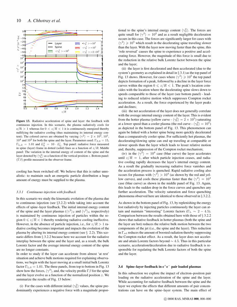
Figure 13. Radiative acceleration of spine and layer: the feedback withcontinuous injection. In this scenario, the plasma radiatively cools forz/R > 1 whereas for 0 < z/R < 1 it is continuously energized therebynullifying the radiative cooling (thus maintaining its internal energy con-tent). The colored curves are obtained by varying 〈γ2〉 = 2 × 10⁵, 105,104 and 102 for both the spine and the layer. Parameters used: ΓS,0 = 15,ΓL,0 = 1.01 and L′′S = 10 · L′L. Top panel: radiative force measuredin spine (layer) frame in dotted (solid) lines as a function of z/R. Middlepanel: The variation in the internal energy of content of the spine and thelayer denoted by 〈γ2
L〉 as a function of the vertical position z. Bottom panel:(Γβ) profile measured in the observer frame.
cooling has been switched off. We believe that this is rather unre-alistic: to maintain such an energetic particle distribution a hugeamount of energy must be supplied to the plasma.
3.3.1 Continuous injection with feedback
In this scenario we study the kinematic evolution of the plasma dueto continuous injection (see §3.2.2) while taking into account theeffects of spine–layer feedback. The initial internal energy contentof the spine and the layer plasmas (〈γ2〉S and 〈γ2〉L respectively)is maintained by continuous injection of particles within the re-gion 0 6 z/R < 1 thereby rendering radiative cooling ineffective.However, in the absence of particle injection, i.e., for z/R > 1 ra-diative cooling becomes important and impacts the evolution of theplasma by altering its internal energy content (see § 2.2). This sce-nario differs from § 3.2.2 because here we account for the radiativeinterplay between the spine and the layer and, as a result, the bulkLorentz factor and the average internal energy content of the spineare no longer constants.In order to study if the layer can accelerate from almost ‘at rest’situation and achieve bulk motions required for explaining observa-tions, we begin with the layer moving at a small initial bulk Lorentzfactor ΓL,0 = 1.01. The three panels, from top to bottom in Fig. 13show how the forces, 〈γ2〉, and, the velocity profile Γβ for the spineand the layer evolve as a function of the normalized position z. Wesummarize the results of Fig. 13 below:
(i) For the cases with different initial 〈γ20〉 values, the spine pre-
dominantly experiences a negative force with a magnitude propor-
tional to the spine’s internal energy content 〈γ2S〉. The forces are
quite small for 〈γ2〉 = 102 and as a result negligible decelerationoccurs in this case. The forces are significantly larger for cases with〈γ2〉 > 105 which result in the decelerating spine traveling slowerthan the layer. With the layer now moving faster than the spine, this‘role reversal’ causes the spine to experience a positive and accel-erating force. However, the magnitude of this force is small due tothe reduction in the relative bulk Lorentz factor between the spineand the layer;
(ii) the layer is first decelerated and then accelerated (due to thesystem’s geometry as explained in detail in § 3.1) as the top panel ofFig. 13 shows. However, for cases where 〈γ2〉 > 105 the top paneldepicts formation of a peak, followed by a decline in the layer forcecurves within the region 0 6 z/R < 1. The peak’s location coin-cides with the location where the decelerating spine slows down tospeeds comparable to those of the layer (see bottom panel) - lead-ing to reduced relative motion which suppresses Compton rocketacceleration. As a result, the force experienced by the layer peaksand declines;
(iii) the net acceleration of the layer does not generally correlatewith the average internal energy content of the layer. This is evidentfrom the hotter plasma (yellow curve - 〈γ2
0〉 = 2× 10⁵) saturatingat a lower speed than a cooler plasma (the red curve - 〈γ2
0〉 = 105)as depicted in the bottom panel of Fig. 13. This phenomenon canagain be linked with a hotter spine being more quickly deceleratedthan a comparatively cooler spine. For sufficiently hot plasmas, thedecelerating/slowing spine can end up traveling at comparable orslower speeds than the layer which leads to lesser relative motionand, thereby, suppression of the Compton rocket mechanism;
(iv) in the 〈γ2〉 = 104 case (blue curve) the layer acceleratesuntil z/R = 1, after which particle injection ceases, and radia-tive cooling rapidly decreases the layer’s internal energy content.As a result the gradually increasing radiative force vanishes andthe acceleration process is quenched. Rapid radiative cooling alsooccurs for plasmas with 〈γ2〉 > 104 (as shown by the red and yel-low curves), and cools these plasmas faster than the 〈γ2〉 = 104
case (blue curve) as shown in the middle panel of Fig. 13. Again,this leads to the sudden drop in the force curves and quenches anyfurther acceleration. The velocity saturation and force quenchingphenomena observed here are identical to those observed in § 3.2.2.
As shown in the bottom panel of Fig. 13, by replenishing the energylost radiatively by injecting particles continuously the layer can at-tain and maintain “interesting” Lorentz factors (ΓL ∼ 2 − 4.5).Comparison between the results obtained here with those of § 3.2.2shows that radiative feedback in hotter plasmas (both the spine andthe layer are hot) reduces the relative bulk motion between the twocomponents of the jet (i.e., the spine and the layer). This reductionin Γrel reduces the amount of boosted radiation thereby suppressingthe Compton rocket effect. As a result, the layer does not acceler-ate and attain Lorentz factors beyond∼ 4.5. Thus in this particularscenario, acceleration/deceleration due to radiative feedback is re-sponsible for regulating the bulk Lorentz factors of both the spineand the layer.
3.4 Spine–layer feedback in e+e− pair loaded plasmas
In this subsection we explore the impact of electron–positron pairloading on the radiative acceleration of the spine and the layer.While accounting for radiative feedback between the spine and thelayer we explore the effects that different amounts of pair concen-trations can have on the spine–layer system. The main effect of
c© 0000 RAS, MNRAS 000, 000–000

Radiative acceleration in spine–sheath blazar jets 11
pairs will be to make the plasma “lighter”, in the sense that the ra-diative force will act on an increased number of leptons, while theinertia is still dominated by the same number of protons (except forthe pair–dominated cases). Therefore the acceleration or the decel-eration will be stronger. The amount of pairs in the plasma can becharacterized by the lepton to proton ratio f (as defined in §2.3) asfollows:
• Pair–free (PF) plasma (f = 1): there is one proton for everyelectron and no pairs are present.• Pair enriched (PE) plasma (f ∼ 20): this plasma is character-
ized by the presence of several electron–positron pairs. The valuef = 20 is about the maximum allowed from considerations aboutthe total power of relativistic jets (Ghisellini & Tavecchio 2010).• Pair dominated (PD) plasma (f → ∞): in this case leptons
dominate the kinematics of the plasma. We show this case for illus-tration, even if it may not be realistic for AGN jets.
We will first study the case without feedback and with the spinemoving with a constant bulk Lorenz factor ΓS = 15. Then wewill study the feedback case, assuming that both the layer and thespine have the same number f of pairs. Within the case withoutfeedback, we will study the extreme cases of a cold plasma (〈γ2〉 =1, Fig. 14) and a hot plasma (〈γ2〉 = 106, Fig. 15). Finally, westudy the feedback case (Fig. 16). The results of these cases aresummarized as follows:
(i) Cold plasma – No feedback — Fig. 14 depicts the force ex-perienced by the layer due to radiation from the spine in the up-per panel. The lower panel depicts the radiative acceleration of thelayer by plotting (Γβ)L as a function of position z/R. We note thatthe force magnitudes are extremely small ∼ 10−21 dyn in com-parison with forces observed in the earlier sections. The pair–freeplasma case is identical to 〈γ2〉 = 1 in § 3.3. Even though theforces are small, the increased pair content decreases the mass ofthe effective particles. Thus the greater the amount of pairs, thegreater the acceleration, as shown by the bottom panel in Fig. 14.
(ii) Hot cooling plasma – No feedback — We consider a hotplasma with 〈γ2〉 = 106 with cooling enabled. Fig. 15 shows theforce experienced by the layer (top panel), the variation of 〈γ2
L〉(middle panel) and the evolution of (Γβ)L (bottom panel) as a func-tion of z/R. As expected, hotter plasmas experience a stronger andnegative initial force which tends to decelerate them. The deceler-ations experienced depend upon the pair content, thereby the pairdominated plasma is decelerated more than the others. This slow-ing down of the plasma leads to a decrease of the (negative) force(due to the decrease of the received radiation energy density). Thisimpacts the cooling rate as well as the force profile for the pair–dominated plasma. The lower cooling rate along with geometricaleffect (entire spine irradiating the layer particle) is responsible forthe burst in acceleration at large values of z.
(iii) Feedback — Now we discuss the third case, where we com-pare hot and cold plasmas with both cooling and feedback enabled.Fig. 16 depicts the evolution of the forces F ′ and F” (upper panel)as measured in the frame of the layer and of the spine, respectively,and (Γβ)L. The forces F ′S experienced by the spine due to the ra-diative interaction with the layer are always negative leading to itsdeceleration. For cold plasmas (with initial 〈γ2〉 = 1) the decel-eration, though small, is non–zero as compared to hot plasma withinitial 〈γ2〉 = 106. We also note that with increasing f values, thedeceleration becomes much stronger.
Similar to the results of previous sections the layer force F ′L (de-noted by the solid curves in the upper panel of Fig. 16) starts off
Figure 14. Radiative acceleration of a cold, pair–loaded layer plasma byvarying lepton to proton ratio f ; we analyze three cases with 〈γ2〉 = 1:no pairs in layer (f = 1); a plasma with f = 20 and the extreme caseof a pair dominated plasma. Parameters used: ΓS = 15, ΓL,0 = 3 andL′′S = 10 · L′L. Top panel: radiative force as measured in the layer frame.Bottom panel: profile of (Γβ)L for the layer.
Figure 15. Radiative acceleration plot for a hot layer plasma having dif-ferent lepton to proton ratios f ; we analyze three distinct cases with aninitial 〈γ2〉z=0 = 106: no pairs in layer and spine plasma (f = 1); a pair–enriched f = 20 plasma, and the extreme case of a pair dominated plasma.Parameters used: ΓS = 15, ΓL,0 = 3 and L′′S = 10 ·L′L. Top panel: radia-tive force measured in layer frame as a function of z/R. Middle panel: theevolution of internal energy of the sheath denoted by 〈γ2
L〉. Bottom panel:profile of (Γβ)L for the layer as a function of z.
c© 0000 RAS, MNRAS 000, 000–000

12 A. Chhotray et al.
Figure 16. Radiative acceleration of the spine–layer pair loaded plasmawith feedback; we compare and analyze three cases with different leptonto proton ratios: no pairs in the layer and spine plasmas (i.e. there is onelepton for each proton - PF); a plasma with f = 20 leptons for each proton(PE) and as the final case, a plasma dominated by pairs (PD). Parametersused: ΓS,0 = 15, ΓL,0 = 3 and L′′S = 10 ·L′L. Top panel: Radiative forcemeasured in spine (layer) frame in dotted (solid) lines as a function of z/R.Middle panel: Profile of (Γβ) for the spine (layer) represented by dotted(solid) lines. Bottom panel: The relative velocity profile of the spine withrespect to the layer expressed as (Γβ)rel.
negative and turns positive (due to geometrical effects). The initialmagnitudes are proportional to both 〈γ2〉 and f . As a result thepair–dominated hot layer is initially significantly decelerated andthen accelerates. At later times, because of cooling the accelerationis no longer a function of 〈γ2〉 but still depends upon the particleratio f . As a result, pair dominated ΓL,sat ∼ 6 and enriched plas-mas ΓL,sat ∼ 3.1 accelerate even for z/R > 5 and much morethan pair–free plasmas.
We can conclude that pair loading enables the plasma to accel-erate significantly even when the plasmas are cold to begin with.Cold pair–enriched and the cold pair–dominated plasma exhibitsignificant acceleration, achieving layer Lorentz factors ΓL ∼ 4and ΓL ∼ 16 respectively.
4 CONCLUSIONS
In this work we have investigated the effects of radiative accelera-tion through Compton scattering in a simple case of structured jet:the spine–layer scenario. We summarize here the several factors wehave explored in our work that influence the dynamical evolutionof a structured jet.
There are two main acceleration regimes:
– Compton Rocket Effect: For the Compton rocket to be effec-tive the leptonic distribution must be hot (〈γ2〉 1). The seed
photons do not directly provide the driving force but act as a cat-alyst for the accelerated motion, in fact the bulk kinetic energy issupplied by the internal energy of the plasma.
– Radiatively Driven Motion/Normal Compton scattering: Forthis case the leptonic distribution of the plasma is cold (〈γ2〉 ∼ 1).The motion is driven solely by Compton scattering photons off coldelectrons. The bulk kinetic energy of the plasma is supplied by theseed photon field due to momentum transfer to the plasma. Theforces and hence the acceleration achieved in this case are small ascompared to the Compton rocket effect.
Having identified the acceleration regimes, we will now summarizeseveral factors important for acceleration:
– Radiative Cooling : Radiative cooling decreases the internalenergy content (〈γ2〉) of the plasma quite rapidly which effectivelykills the force – thereby quenching the acceleration process. Thus itplays an important role in determining whether the Compton rocketeffect or the radiatively driven motion dominates the kinematics ofthe structured jet. In §3.1 we discussed how an initially hot plasmaexperiences a decelerating force for small values of z due to radi-ation directed along the negative z direction or coming from spineregions located above the layer. As the plasma decelerates, it willsimultaneously cool rapidly if radiative cooling is active. The mag-nitude of this decelerating force decreases due to two reasons –i) rapid cooling and ii) as the plasma travels further away fromthe base it receives some upward directed photons from the base(which is now to the rear of the layer plasma) pushing the layerplasma along the positive z direction. As a result, the magnitude ofthe decelerating force rapidly decreases and it does not produce asignificant change in ΓL values. As noted in § 3.2.2, the radiativecooling activated by low or moderate spine luminosities quenchesthe acceleration process – which effectively freezes the Lorentz fac-tor of the layer at the value it had just before activation.
– Feedback: the feedback scenario enables us to study the self–consistent evolution of the spine and layer under the radiative in-fluence of the layer and the spine respectively. Among the caseswe studied, in the cooling regime neither the spine nor the layershows any acceleration. In some cases, the layer accelerates andeven overtakes the spine – but this requires a continuous injectionof huge (and possibly unrealistic) amounts of energy. In the non–cooling or continuous energy injection regime, for 〈γ2〉 > 2×10⁴,significant accelerations can be seen for the layer and decelerationsfor the spine. Interestingly, by making the situation more realisticby limiting energy injection (having a energy injection limited tothe active region as explored in § 3.2.2 and § 3.3.1) and by incor-porating radiative cooling - the layer achieves Lorentz factors ∼ 3comparable to those required by observations. Thus radiative feed-back induced acceleration plays in important role in regulating thebulk Lorentz factors of both the spine and the layer.
– Pair–loading: If electron positron pairs are present, they de-crease the effective mass of the plasma. As a result, the same forces(for non pair loaded plasmas) can accelerate pair loaded plasmasto higher Lorentz factors. Furthermore, even cold pair–loaded plas-mas can attain high ΓL values as compared to non pair–loaded plas-mas, as shown in Fig. 14.
– Factors influencing acceleration: the luminosity and the in-ternal energy content of the plasma play a very important role inthe acceleration process. In general, the greater the luminosity thegreater the observed acceleration. The same is true for the amountof the internal energy that can be converted into bulk motion by theCompton rocket effect. But this depends critically on the presenceof same re–acceleration mechanism, able to maintain the plasma
c© 0000 RAS, MNRAS 000, 000–000
Radiative acceleration in spine–sheath blazar jets 13
hot. In several scenarios explored, the maximum of the accelerat-ing force occurs outside the active or the standing shock region– when the spine/layer particle observes the entire layer/spine ir-radiating it and thereby pushing it along the positive z direction.This effect was first noticed while investigating the (rather unreal-istic) no cooling scenario (see § 3.1 where cooling was permanentlyswitched off).
Regarding the possibility that the layer can be entirely acceleratedby the radiative force, we can conclude that this is possible if theCompton rocket effect remains strong for a sufficiently long time,namely for the time needed to cross the active region z ∼ R.This requires that 〈γ2〉 remain large (∼>104) within the layer, andthis in turn demands continuous injection of fresh energetic leptonsthroughout the layer length. Electrons–positron pairs can help, butare not crucial, since the maximum number of pairs per proton islimited.
If the magnetic field within the layer is B, we expect that itssynchrotron emission peaks at νS,L ∼ 3.6×10⁶γ2
bBδL. Accordingto Eq. 6 (with γmax γb) we have γ2
b ∼ 108(〈γ2〉/104)2 leadingto νS,L ∼ 3.6× 10¹⁴(〈γ2〉/104)2BδL Hz. For B ∼1 G, similar tothe magnetic field of the spine of blazars in the γ–ray emitting zone(Tavecchio & Ghisellini 2015), we have that layers accelerated ra-diatively should peak in the optical–UV band, and there should bea relation between their synchrotron peak frequency and their bulkLorentz factor. The higher νS,L the larger ΓL, and the smaller therelative Γ between the spine and the layer.
On the contrary, if νS,L is small, then 〈γ2〉 is also small, sug-gesting ΓL ∼ 1. Although the relative Γ approaches ΓS, the radia-tive interplay between the two structures should be weak, since thelayer cannot produce many seed photons if its 〈γ2〉 is small.
There is therefore a defined range of νS,L where radiative ac-celeration of the layer can work. If νS,L is in the far infrared andwe have indications that ΓL ∼ 3 or more, then it is very likely thatthe layer was not accelerated radiatively, but by the same processthat accelerated the spine. The model can thus be tested studyingthe spectral energy distribution of blazars and radio–galaxies. Theblazars where we can reliably derive the spectral parameters of thelayer are still too few to draw any strong conclusions. For radio–galaxies, we should be careful to select those whose observed emis-sion is reliably associated to a layer located in the inner region ofthe relativistic jets, and not to more extended components. So, theselected sources should show rapid variability indicating a compactemitting region.
We have thus shown how structured spine–sheath jets are ra-diatively accelerated in the Compton rocket and radiatively drivenmotion regimes. We have considered different values of Lorentzfactors, luminosities and internal energy contents to understand thedetails of the acceleration process and have been successful in de-veloping some insight and intuition regarding the phenomena. Wehave also shown that by including radiative feedback (between thespine and the layer), radiative cooling and a realistic energy injec-tion model (the continuous injection scheme within the active re-gion) the observed Lorentz factor of the layer can be reproduced.We have also proposed tests for our model by utilizing layer asso-ciated emissions from inner parts of radio-galaxy jets. The rangeof our obtained Lorentz factors predict that radiatively acceleratedlayers’ synchrotron peak values νS,L occur in the IR-optical band.
ACKNOWLEDGMENTS
GG and FT acknowledge contribution from a grant PRIN–INAF–2014. AC thanks and appreciates GG and INAF, Brera for theirhospitality at Merate, IT.
REFERENCES
Abdo A.A., Ackermann M., Ajello M. et al., 2010, ApJ, 720, 912Begelman M.C., Blandford R.D. & Rees M.J.,???Bodo G., Rossi P., Mignone A., Massaglia S. & Ferrari A., 2003, NewAR,
47, 557D’Ammando F., Orienti M., Tavecchio F. et al., 2015, MNRAS, 450, 3975Edwards P.G. & Piner B.G., 2002, ApJ, 579, L70Ferrari A., 1998, ARA&A, 36, 539Georganopoulos M. & Kazanas D., 2003, ApJ, 594, L27Ghisellini G., Tavecchio F. & Chiaberge M., 2005, A&A, 432, 401Ghisellini G. & Tavecchio F., 2010, MNRAS, 409, L79Ghisellini G. & Tavecchio F., 2015, MNRAS, 448, 1060Giroletti M., Giovannini G., Feretti L. et al., 2004, ApJ, 600, 127Giroletti M., Giovannini G., Taylor G.B. & Falomo R., 2006, ApJ, 646, 801Grandi P., 2012, Intern. J. of Modern Physics Conference Series, 8, 25Henri, G. & Pelletier, G. 1991, ApJ, 383, L7Katarzynski K., Sol H. & Kus A., 2003, A&A, 410, 101Kino M., Takahara F. & Kusunose M., 2002, ApJ, 564, 97Konopelko K., Mastichiadis A., Kirk J., De Jager O.C. & Stecker F.W.,
2003, ApJ, 597, 851Krawczynski H., Coppi P.S. & Aharonian F., 2002, MNRAS, 336, 721Lazzati D. & Begelman M.C., 2005, ApJ, 629, 903Lind K.R. & Blandford R.D., 1985, ApJ, 295, 358McKinney J. C., 2006, MNRAS, 368, 1561O’Dell S.L., 1981, ApJ, 243, L147Piner B.G. & Edwards P.G., 2004, ApJ, 600, 115Piner B.G., Pant N., & Edwards P.G., 2010, ApJ, 723, 1150Piner B.G., Pant N., & Edwards P.G., 2008, ApJ, 678, 64Piner B.G. & Edwards P.G., 2014, ApJ, 797, 25Piner B.G. & Edwards P.G., 2014 ApJ, 797, 25Rossi E.M., Lazzati D. & Rees, M.J., 2002, MNRAS. 332, 945Rybicki G.B. & Lightman A.P., 1979, Radiative Processes in Astrophysics,
New Youk, Wiley InterscienceSbarrato T., Padovani P. & Ghisellini G., 2014, MNRAS, 445, 81Sikora M., Madejski G., Moderski, R. & Poutanen, J., 1997, ApJ, 484, 108Sikora M., Sol H., Begelman M.C., & Madejski G.M., 1996, MNRAS, 280,
781Tavecchio F. & Ghisellini G., 2008, MNRAS, 385, L98Tavecchio F. & Ghisellini G., 2009, MNRAS, 394, L131Tavecchio F. & Ghisellini G., 2014, MNRAS, 443, 1224Tavecchio F. & Ghisellini G., Ghirlanda G., Foschini L. & Maraschi L.,
2010, MNRAS, 401, 1570Tavecchio F., Ghisellini G. & Guetta D., 2014, ApJ, 793, L18Tavecchio F., Maraschi L., Pian E. et al., 2001, ApJ, 554, 725Vuillaume T., Henri G. & Petrucci P.–O., 2015, A&A, 581, A18Weinberg S., 1972, Gravitation and cosmology. Principles and applications
of the General Theory of Relativity, J. Wiley & Sons (New York)—————————————————
APPENDIX A: DETAILS OF FORCE CALCULATION
Consider an element of the layer at position z; we call dU ′ thedifferential energy density of the spine radiation received from anangle between θ and θ + dθ, measured in the frame of the layer.The contribution of this radiation energy density to the infinitesimalforce dF ′z parallel to the jet axis and acting on the layer particle is
c© 0000 RAS, MNRAS 000, 000–000
14 A. Chhotray et al.
given by:
dF ′z =16
9σT〈γ2〉 cos θ′dU ′ (A1)
where θ′ is the angle of incoming photons with respect to the jetaxis direction as seen by the layer. The total force exerted on thelayer’s effective particle can be computed by integrating the Eq.A1 over the incoming angles θ′. Since the spine is active betweenpoints that are fixed in the observer frameK, it is easier to computethe integral in that frame K. From the relations of aberration of thelight (e.g. Weinberg, 1972) we have useful transformations:
cos θ′ =cos θ − βL
1− βL cos θ(A2)
dΩ′ = dΩ · δ2L (A3)
The differential radiation energy density can be written as:
dU ′
dΩ′=
I ′
c(A4)
where I ′ is the bolometric radiation intensity as seen by the layerand it is related to the spine comoving radiation intensity I ′′ by:
I ′ = I ′′ · δ4S,L (A5)
Consider now that the uni–dimensional spine is actually an in-finitesimal cylinder whose axis is coincident with the jet axis ofheight R and radius r → 0. In this case we have:
I ′′ = j′′ · r = λ′′S1
πr(A6)
where j′′ is the comoving spine emissivity. λ′′S =
[dL′′Sdx′′
]is the
comoving spine luminosity linear density profile; it is generally afunction of the position z, but in case of uniform luminosity distri-bution we can write:
λ′′S =dL′′Sdx′′
=L′′SR′′
=L′′SΓS
R(A7)
where R′′ = R/ΓS is the length of the spine active region mea-sured in the frame comoving to the spine. L′′S is the total comovingluminosity of the spine and it is related to the observed isotropicluminosity by (see Lind & Blandford, 1985):
LS,iso = L′′Sδ3S(θview) =
L′′SΓ3
S(1− βS cos θview)3(A8)
where θview is the angle between the jet axis and the line of sight.That relation is different from the usual one (that requires a factorδ4 between the rest frame and the isotropic luminosity) because inthis case there the rest frame emitting volume properly is ill-definedas the end points of the emitting region are moving with respect tothe emitting fluid. We can relate the observed luminosity densityλS with the comoving one through Eq. A9:
λS =LS,iso
R= λ′′S
δ3S(θview)
ΓS(A9)
Using the definition of solid angle dΩ we can write:
dΩ =dA
D2=
dx · 2rD2
=dθ · 2brD2 sin2 θ
=2r
bdθ (A10)
where dA = 2rdx is the differential area of the spine seen underthe angle dΩ, D = b/ sin θ is the distance between the emittingelement of the spine and the layer, x = −D cos θ = −b cot θ is
the projection of D over the jet axis. Using eqs. 3, A3, A4, A5, A6,A10, we can write:
dU ′(θ)
dθ= λ′′Sη
δ4S
δ2L
1
bc(A11)
that depends no more on r → 0. In Eq. A11, η is a factor of theorder of unity that depends on the geometry (in our case we use η =2/π). The total force exerted on the layer test particle is obtainedintegrating Eq. A1:
F ′z =16
9
σT
bc〈γ2〉η
∫ θ2
θ1
λ′′Sδ4S
δ2L
cos θ − βL
1− βL cos θdθ (A12)
The limits of integration θ1 and θ2 are measured in the central en-gine frame (comoving to the limits of the emitting volume) anddepend only on the position of the layer z:
cos θ1 =z
(b2 + z2)1/2(A13)
cos θ2 =z −R
(b2 + z2 +R2 − 2Rz)1/2(A14)
Evaluating the force at each value of z we can obtain the layerLorentz factor profile ΓL(z) by numerically solving Eq. 10.
c© 0000 RAS, MNRAS 000, 000–000