Embed Size (px)
Citation preview


ON-LINE DIAGNOSTIC ON HV BUSHINGS
42ND IIEE ANNUAL NATIONAL CONVENTION
NOVEMBER 18, 2017
SMX CONVENTION CENTER, PASAY CITY
Engr.Eduardo M. Pabuna Jr. Manager, Technical Solutions
Presented by:

AGENDA:
• Role of HV Bushings
• Bushing Insulation Construction
• Bushing Typical Design and Technologies
• Common Bushing Failure Mechanism
• On-line Measurement Technology
• Installations & Case Studies

ROLE of HV BUSHINGS
A bushing is simply a device that allows a
conductor to pass through a barrier: it has
an insulating medium, which must be
sustained to prevent the passage of
excess current to ground.

BUSHINGS INSULATION CONSTRUCTION

TYPICAL BUSHING DESIGN
Capacitor/Condenser Type:
RBP-Resin Bonded Paper (Start 1913)
OIP-Oil Impregnated Paper (Since 1950s)
RIP-Resin Impregnated Paper (Since 1960s)
RIS-Resin Impregnated Synthetics (Since 2010)
Non-Condenser Type:
Solid
Alternate Layers of Solid
and Liquid Insulation
Gas-Filled
RIS
Transformer Bushing Technologies
Oil Impregnated Paper Resin Impregnated Paper Resin Impregnated Synthetic

PERFORMANCE AND RISK COMPARISON
OIP
•Excellent PD
•Cost effective
•Overloading capability
•But..
•Explosion risk
•Maintenance required •Needs careful handling
& storage to avoid damage •Can absorb moisture over time
RIP
•Excellent PD
•Much Safer No Explosion
Risk
•Less Maintenance
•But..
•Sensitive to Moisture
•Still needs special dry
Storage •Less overloading Capability
RIS
•Same Excellent Safety &
Less Maintenance
•Excellent PD
•Best Possible Moisture
Performance
•Shorter Manufacturing
Time
•But..
•Less overloading capability
•Only Available up to
170KV

COMMON BUSHING FAILURE MECHANISM
•AGEING
•CONTAMINATION
•CRACKING
•EXCESSIVE MOISTURE
•LEAKING
•LIGHTNING
•PARTIAL DISCHARGE
•SYSTEM EVENT

ON-LINE MEASUREMENT TECHNOLOGY
ABSOLUTE MEASUREMENT RELATIVE MEASUREMENT
The approach of determining the capacitance and percent power factor
of an insulating medium relies on measuring the real and reactive
components of the leakage current through the test specimen.

ABSOLUTE MEASUREMENT
• For traditional off-line capacitance/power factor measurements, that
reference is the applied voltage. Reporting the leakage current vector
angle with reference to the applied voltage constitutes an ABSOLUTE
MEASUREMENT (True Power Factor)

RELATIVE MEASUREMENT
• On-line measurements rely on the leakage current of another bushing
as the reference, signifying the leakage current vector is being
measured relative to another bushing.
• The relative measurement method, with the middle current vector used
as the reference. The limitation of this approach is that the on-line
measurement provides a relative value which can only identify change.
.
A
.
B
.
C
C2
C1
C1
C1
C2
C2
IA
IC
IB
I
..
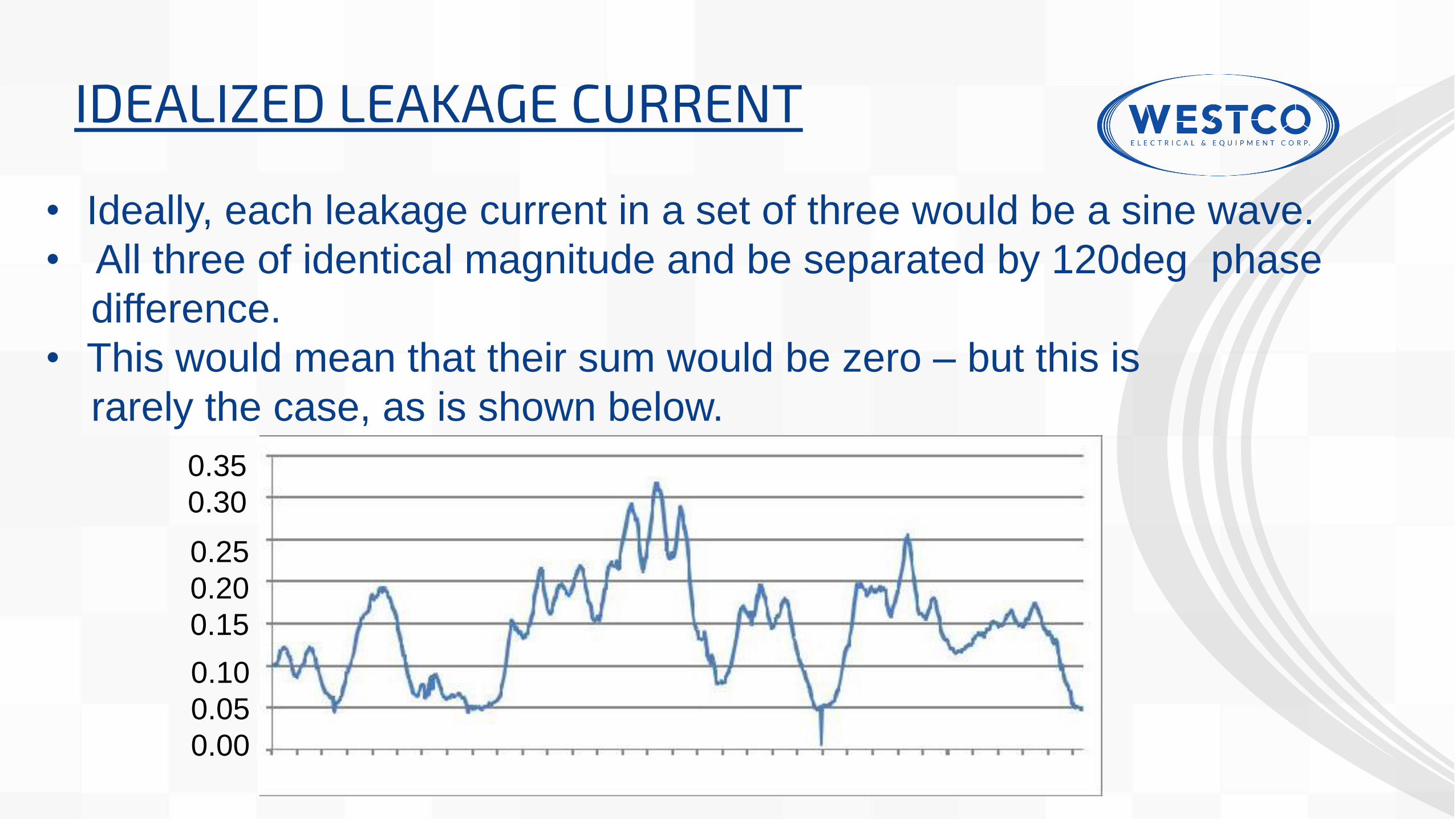
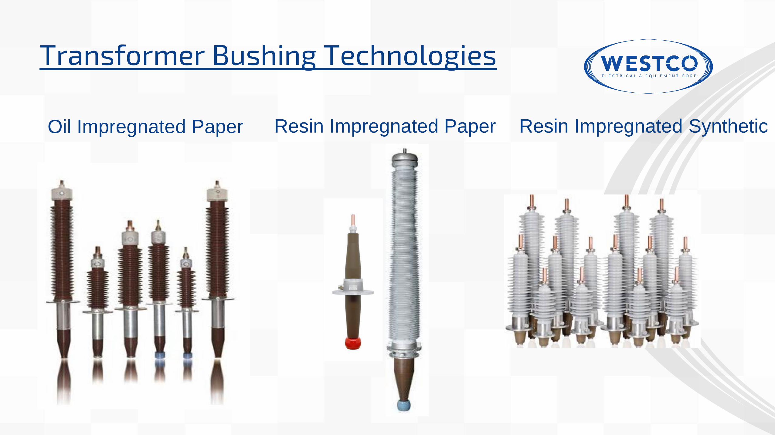
IDEALIZED LEAKAGE CURRENT
• Ideally, each leakage current in a set of three would be a sine wave.
• All three of identical magnitude and be separated by 120deg phase
difference.
• This would mean that their sum would be zero – but this is
rarely the case, as is shown below.
0.10
0.05
0.00
0.25
0.20
0.15
0.35
0.30

THE NEW DOBLE APPROACH
• Analyzing individual currents, and the raw data which gives the
currents provide much more information.
• dPrime IDD™ applies an expert system to learn what is normal
at each set of bushings
• In addition, limit values are set which provide a means to
identify insulation degradation.

SIMPLE CONNECTION
Bushing Monitoring Device
DOBLE IDD
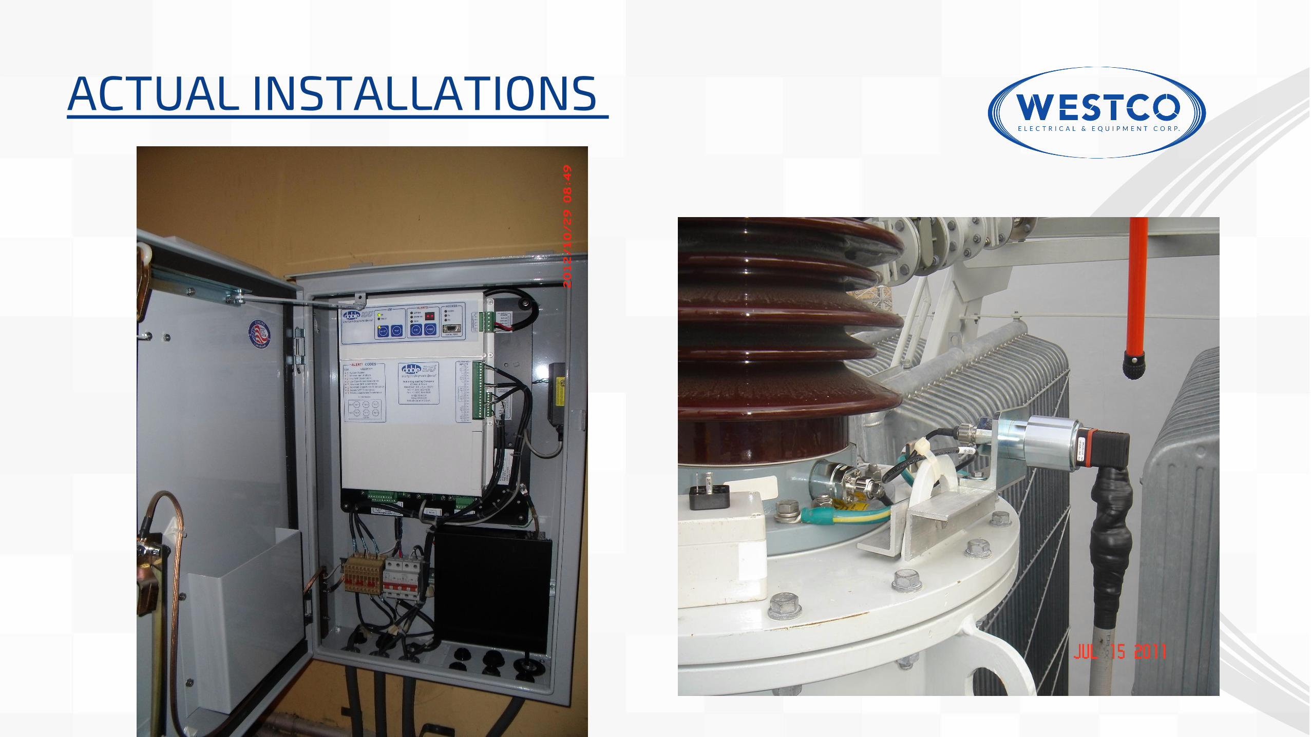
ACTUAL INSTALLATIONS

ACTUAL INSTALLATIONS
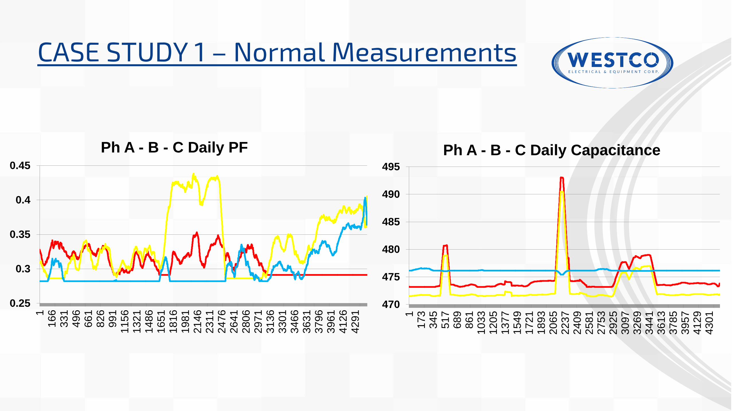
CASE STUDY 1 – Normal Measurements
470
475
480
485
490
495
11
73
34
55
17
68
98
61
10
33
12
05
13
77
15
49
17
21
18
93
20
65
22
37
24
09
25
81
27
53
29
25
30
97
32
69
34
41
36
13
37
85
39
57
41
29
43
01
Ph A - B - C Daily Capacitance
0.25
0.3
0.35
0.4
0.45
11
66
33
14
96
66
18
26
99
11
15
61
32
11
48
61
65
11
81
61
98
12
14
62
31
12
47
62
64
12
80
62
97
13
13
63
30
13
46
63
63
13
79
63
96
14
12
64
29
1
Ph A - B - C Daily PF

CASE STUDY 2- Power Factor Deterioration
0
0.5
1
1.5
2
2.5
POWER FACTOR GRAPH
Daily %PF1 Daily %PF3
CONCLUSION
• Bushing monitoring requires appropriate data in depth and
with built in expert system analysis.
• More than just a simple capacitance measurement or sum
current approach.
• The online technology has proven to be a valuable tool for
insuring the reliability of the apparatus, especially in an
environment where outages are rarely available.
REFERENCES
• UPDATE ON ON-LINE BUSHING DIAGNOSTICS
Robert C. Brusetti, P.E.
Doble Engineering Company
73RD Annual Doble Client Conference
• Bushing Monitoring – more than just sum current, Rev 1.0
Doble Engineering Company
• Why Transformer Bushing Fails
Dr. HongZhi Ding and Dr. Richard Heywood
2015 EuroDoble Colloquium and Workshop

Thank You!
Questions?
8F 68 Kalayaan VCP Building, 68 Kalayaan Avenue, Teachers Village West, Quezon City 1101 +63 2 365 00 68 [email protected]
www.westco-phil.com
Address: Tel No.: Email:
Website: