Embed Size (px)
Citation preview

Progress report on theHV-SQUID Compatibility Test
• Study the SQUID performance in a HV environment.
• Study the HV breakdown
– in superfluid under pressure.
– using different materials for electrodes.
Craig Huffer, Maciej Karcz, Chen-Yu Liu, Josh Long
Indiana University

Instabilities in the SQUID sensor
• Adding current bypass capacitors to the ground → filter the high frequency components from possible sparks → SQUID more stable.
• SQUID feedback circuit.– A larger RC constant of the FB integrator helps(?) → increases the BW of the system → makes
the SQUID operation less susceptible to frequent HV polarity switches.

Capability of the HV-SQUID probe
• What can we test:– Without a SQUID sensor, measure
• HV breakdown (dielectric strength) in liquid helium from 1.5K (1torr) - 5K (1500 torr), in a small gap (1mm ~ 1cm).
• HV breakdown in superfluid helium under pressure.• HV breakdown with candidate electrode materials.• Leakage current through candidate cell materials.
– With a SQUID sensor• Mitigate Radio Frequency Interference (RFI)
– From different power supplies (SMPS vs Linear )– From micro-discharge (occurs below breakdown voltage) in
dielectrics which makes the electrode, cell, etc...
• Measure Johnson Noise– candidate material for electrode, RF shield, and ferromagnetic
shield.
• Investigate HV Breakdown vs SQUID survival rate

Pressurization in the test probe
• Small size, top load probe allows easy access and short turn-over time for various changes.
• We have changed the bellows scheme to a gas scheme.
1. Close the superfluid-tight needle valve to isolate the test probe from the helium reservoir.
2. P inside the test probe can be changed with pressurized helium gas introduced through a pressurization port.
3. T of the probe can be controlled by the helium reservoir, which can be pumped on.
to pump
17” 6.25”
2.7”

• An Old Janis helium dewar
• Pressure manometers– Baratron
• A dry pump

The HV conductor is placed inside a SS tube (can be evacuated.) This protects the HV line from breakdown in helium vapor.
Radiation Baffles
Superfluid-tight needle valve
Enough room below the ground electrode to accommodate different SQUID sensors & pickup coils.
Probe can (can be evacuatedor pressurized)
HV pumping port
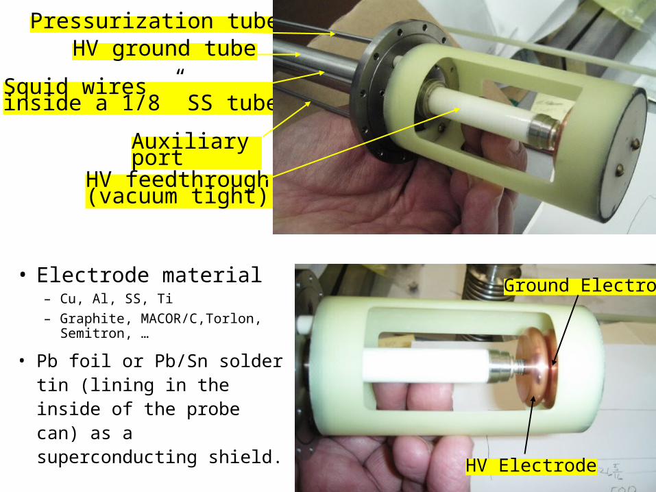
• Electrode material– Cu, Al, SS, Ti
– Graphite, MACOR/C,Torlon, Semitron, …
• Pb foil or Pb/Sn solder tin (lining in the inside of the probe can) as a superconducting shield.
HV feedthrough (vacuum tight)
Squid wiresinside a 1/8” SS tube
Auxiliary port
Pressurization tubeHV ground tube
HV Electrode
Ground Electrode

SQUID Electronics
D. Drung, Supercond. Sci. Technol. 16 (2003) 1320
Pickup coil
Input coil

Why is RFI bad for SQUIDs?
1. SQUID feedback unlock with a high frequency input– Traditional flux lock loop (FLL) uses the modulation/PSD scheme
to overcome the high low frequency noise from the pre-amp.– Does not track signal with frequencies higher than the ½ of the
modulation frequency.
2. RF can heat up the SQUID component locally, changing the V- curve.
– was applied to image microwave cavity.
3. Large transient induces big current in the SQUID thin film→trap flux→change V- curve.
RF shield the SQUID sensor
RF shield the input coil, use large BW, high slew rate electronics

BW & Slew Rate
• Current system (StarCryoelectronics: PCI1000+ PFL 100)– modulation frequency: 256 kHz– BW: max=100kHz– BW is effected by
• time constant of the integrator • the feedback coupling (the tighter the
coupling, the lower the BW)
fbampdB R
MVf
int
mod3 2
Magnicon + PTB BerlinAdditional Positive Feedback (APF) amplifies the voltage signal, allows for direct coupling without modulation.Fast electronics, large BW (6MHz, 20MHz), large slew rate ~ MPhi0/s, in a low gain, should be able to track fast transients, keeping the SQUID locked under RFI.

Large, fast transients
• HV reversal– Reset (in sync with field reversal)
• shunt the integrator capacitor (flux lock mode off, SQUID sees all the field)
• Micro-discharge (random events)– Shield the SQUID sensor (inside a Pb box)– RF shield the pickup coil
• Mylar foil with Au, Al coating (superinsulation)
– Enhance low pass filter across the input coil• RC filter in parallel to the input coil • could introduce a pole in the frequency response

RF Shield vs Johnson Noise
• Skin depth:
• Magnetic Johnson Noise:Aluminized mylar superinsulation
– t=1m, z=1cm, SB=1.13 fT/Hz
– t=1m, z=10cm, SB=0.11 fT/Hz
– t=300m, z=1cm, SB=19 fT/Hz
2
d
skin depth (m)
material resistivity (Ohm-m) conductivity mu 100kHz 1MHz 20MHz 1Hz
Ag 1.47E-08 6.80E+07 1.25704E-06 0.000192983 6.10267E-05 1.3646E-05 0.061027
Cu 1.72E-08 5.81E+07 1.25704E-06 0.000208749 6.60124E-05 1.4761E-05 0.066012
Au 2.44E-08 4.10E+07 1.25704E-06 0.000248631 7.86242E-05 1.7581E-05 0.078624
Al 2.82E-08 3.55E+07 1.25704E-06 0.000267292 8.45251E-05 1.89E-05 0.084525
Al 10.5233006 3.327759838 mils
)(8)( 0, tzz
tTkBS B
ZnB
t : thichnessz : separation
J. Nenonen, et al, Rev. Sci. Instrum. 67, 2397
: conductivity
ztf dB 4
13

Different SQUID sensors
• Quantum Design Squid– Katchen type construction
• SQUID loop consist of large area Nb film to enhance the coupling with the input coil
• However, tends to trap flux easily
• Jena Squid (Supracon)– Nb thin wire loops
• Connected in parallel to keep the inductance small, but still has a large area for efficient coupling to the input coil.

HV power supply options
• Switch mode power supply (SMPS)– Commonly available– Severe RFI
• Linear power supply – Might be hard to find, probably needs to be custom-made.
• Array of dry cell batteries – Eveready (model 497), Zn/MnO2, 510V, 140 mAh, ~$75/each– For nEDM exp., we need 686 in series to supply 350kV– C~100pF, Q=CV=3.510-5C for each charge– The battery pack could provide 140mAh/Q = 1.4107 charges (recharge every 1 hr, will last ~1620 years)
14.29 cm
7.62 cm
4.12 cm

Current limited battery array
+
7
8
2arg
52arg
max
102arg#
105.2
1000500)140(
5.122
1
105.2)(1000
5001
10005001000
1
esch
j
VmAhqVE
jCVE
jRCRIE
kRmA
VR
mAIset
storedbattery
echC
echR
+
+
+
C~100pF

Progress
• Parts are machined, waiting for the final welding assembly.
• Janis cryostat is cleaned up, leak checked and ready to go.
• SQUID sensors (QD, CryoElectronics) and control electronics (CryoElectronics) have arrived; have to order Jena SQUID sensors.
• Cool down in the next 1~2 weeks.• Results expected before the DOE review.