Embed Size (px)
Citation preview
920-061E
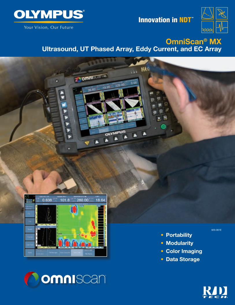
OmniScan® MX Ultrasound, UT Phased Array, Eddy Current, and EC Array
• Portability
• Modularity
• Color Imaging
• Data Storage
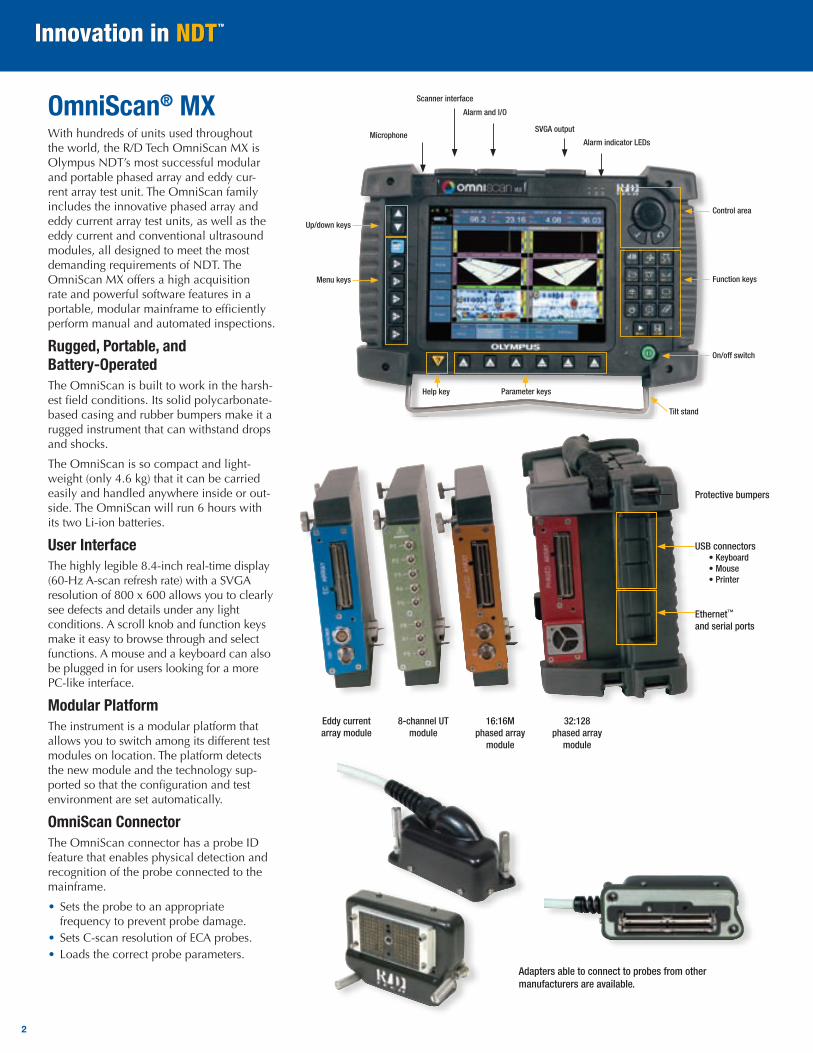
OmniScan® MXWith hundreds of units used throughout the world, the R/D Tech OmniScan MX is Olympus NDT’s most successful modular and portable phased array and eddy cur-rent array test unit. The OmniScan family includes the innovative phased array and eddy current array test units, as well as the eddy current and conventional ultrasound modules, all designed to meet the most demanding requirements of NDT. The OmniScan MX offers a high acquisition rate and powerful software features in a portable, modular mainframe to efficiently perform manual and automated inspections.
Rugged, Portable, and Battery-OperatedThe OmniScan is built to work in the harsh-est field conditions. Its solid polycarbonate-based casing and rubber bumpers make it a rugged instrument that can withstand drops and shocks.
The OmniScan is so compact and light-weight (only 4.6 kg) that it can be carried easily and handled anywhere inside or out-side. The OmniScan will run 6 hours with its two Li-ion batteries.
User InterfaceThe highly legible 8.4-inch real-time display (60-Hz A-scan refresh rate) with a SVGA resolution of 800 x 600 allows you to clearly see defects and details under any light conditions. A scroll knob and function keys make it easy to browse through and select functions. A mouse and a keyboard can also be plugged in for users looking for a more PC-like interface.
Modular PlatformThe instrument is a modular platform that allows you to switch among its different test modules on location. The platform detects the new module and the technology sup-ported so that the configuration and test environment are set automatically.
OmniScan ConnectorThe OmniScan connector has a probe ID feature that enables physical detection and recognition of the probe connected to the mainframe.
• Sets the probe to an appropriate frequency to prevent probe damage.
• Sets C-scan resolution of ECA probes.• Loads the correct probe parameters.
2
Adapters able to connect to probes from other manufacturers are available.
Microphone
Scanner interface
Alarm and I/O
SVGA output
Alarm indicator LEDs
Up/down keys
Menu keys
Help key Parameter keys
On/off switch
Function keys
Control area
Tilt stand
Eddy current array module
8-channel UT module
16:16M phased array
module
32:128 phased array
module
Protective bumpers
USB connectors• Keyboard• Mouse• Printer
Ethernet™ and serial ports

3
Setup and Report• Setup storage compatible with Microsoft® Windows®
(exportable using a CompactFlash® card)• Complete report setup including reading configuration,
which can be customized using HTML page layout• On-screen interactive help that can be customized for
procedure-oriented setups using HTML script templates• Setup preview• Predefined setups
Connectivity, Data Storage, and ImagingThe OmniScan® offers alarm outputs as well as the standard PC ports: USB, SVGA out, and Ethernet™. It offers inter-nal data storage capability and extended storage via a CF (CompactFlash®) card slot, as well as any USB or network storage.
Typical Applications Girth Weld InspectionOlympus NDT has developed a circumferential weld inspection system based on the OmniScan PA for the oil and gas industry. This phased array system is qualified to in-spect tube with diameters ranging from 48 mm to 1524 mm and thicknesses from 5 mm to 25 mm in compliance with ASME Boiler and Pressure Vessel Code Section V. The semiautomated system offers better inspection speed and detection, and makes the interpre-tation of the indications significantly easier.
Pressure Vessel Weld InspectionThe combination of time-of-flight diffraction (TOFD) and pulse-echo techniques means that the complete inspection is done in a single scan, significantly reducing the inspection time when compared to conventional raster scanning or radiography. Inspection results are avail-able instantaneously, allowing you to spot a problem with the welding equipment and fix it right away. Based on our vast experience in the nuclear and petrochemical industries, this system includes all the functions that are needed for code-compliant weld inspections.
Scribe Marks Inspection with No Paint RemovalThe Flight Standards Information Bulletin for Airworthiness (FSAW 03-10B), issued on No-vember 2003, report damage along fuselage skin lap joints, butt joints, and other areas of several aircraft caused by the use of sharp tools used during paint and sealant removal.
The OmniScan allows the scribe marks inspection to be done without paint removal which is a huge time saver. The inspection is done in a single pass using 60º to 85º SW sector scans. OmniScan PA is now referenced in the Boeing NTM manuals, 737 NDT Manual, Part 4, 53-30-06, July 2005.
Aircraft Fuselage InspectionThe OmniScan ECA (eddy current array) provides the ability to detect hidden corrosion and cracks in multilayer structures. Currently, material loss of 10% of the lap splice thickness can be detected in aluminum at a depth of 0.2 in. Surface and subsurface cracks can be detected in the skin, at the fastener, or at the lap joint edges.
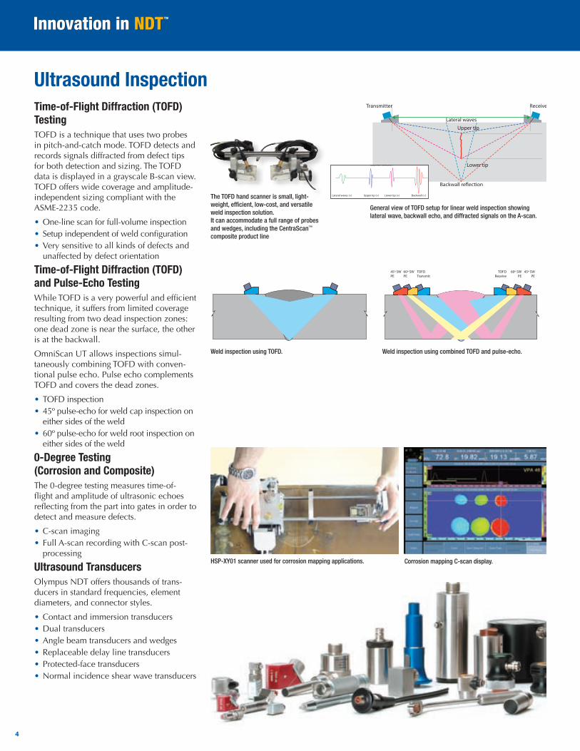
Time-of-Flight Diffraction (TOFD) TestingTOFD is a technique that uses two probes in pitch-and-catch mode. TOFD detects and records signals diffracted from defect tips for both detection and sizing. The TOFD data is displayed in a grayscale B-scan view. TOFD offers wide coverage and amplitude-independent sizing compliant with the ASME-2235 code.
• One-line scan for full-volume inspection• Setup independent of weld configuration• Very sensitive to all kinds of defects and
unaffected by defect orientation
Time-of-Flight Diffraction (TOFD) and Pulse-Echo TestingWhile TOFD is a very powerful and efficient technique, it suffers from limited coverage resulting from two dead inspection zones: one dead zone is near the surface, the other is at the backwall.
OmniScan UT allows inspections simul-taneously combining TOFD with conven-tional pulse echo. Pulse echo complements TOFD and covers the dead zones.
• TOFD inspection• 45º pulse-echo for weld cap inspection on
either sides of the weld• 60º pulse-echo for weld root inspection on
either sides of the weld
0-Degree Testing (Corrosion and Composite)The 0-degree testing measures time-of-flight and amplitude of ultrasonic echoes reflecting from the part into gates in order to detect and measure defects.
• C-scan imaging • Full A-scan recording with C-scan post-
processing
Ultrasound TransducersOlympus NDT offers thousands of trans-ducers in standard frequencies, element diameters, and connector styles.
• Contact and immersion transducers• Dual transducers• Angle beam transducers and wedges• Replaceable delay line transducers• Protected-face transducers• Normal incidence shear wave transducers
Ultrasound Inspection
4
General view of TOFD setup for linear weld inspection showing lateral wave, backwall echo, and diffracted signals on the A-scan.
Transmitter Receiver
Lower tip
Upper tip
Backwall (+) Lower tip (+) Upper tip (+) Lateral waves (+)
Lateral waves
Backwall reflection
Transmitter Receiver
Lower tip
Upper tip
Backwall (+) Lower tip (+) Upper tip (+) Lateral waves (+)
Lateral waves
Backwall reflection
The TOFD hand scanner is small, light-weight, efficient, low-cost, and versatile weld inspection solution. It can accommodate a full range of probes and wedges, including the CentraScan™ composite product line
TOFDTransmit
60º SWPE
45º SWPE
45º SWPE
60º SWPE
TOFDReceive
Weld inspection using TOFD. Weld inspection using combined TOFD and pulse-echo.
HSP-XY01 scanner used for corrosion mapping applications. Corrosion mapping C-scan display.
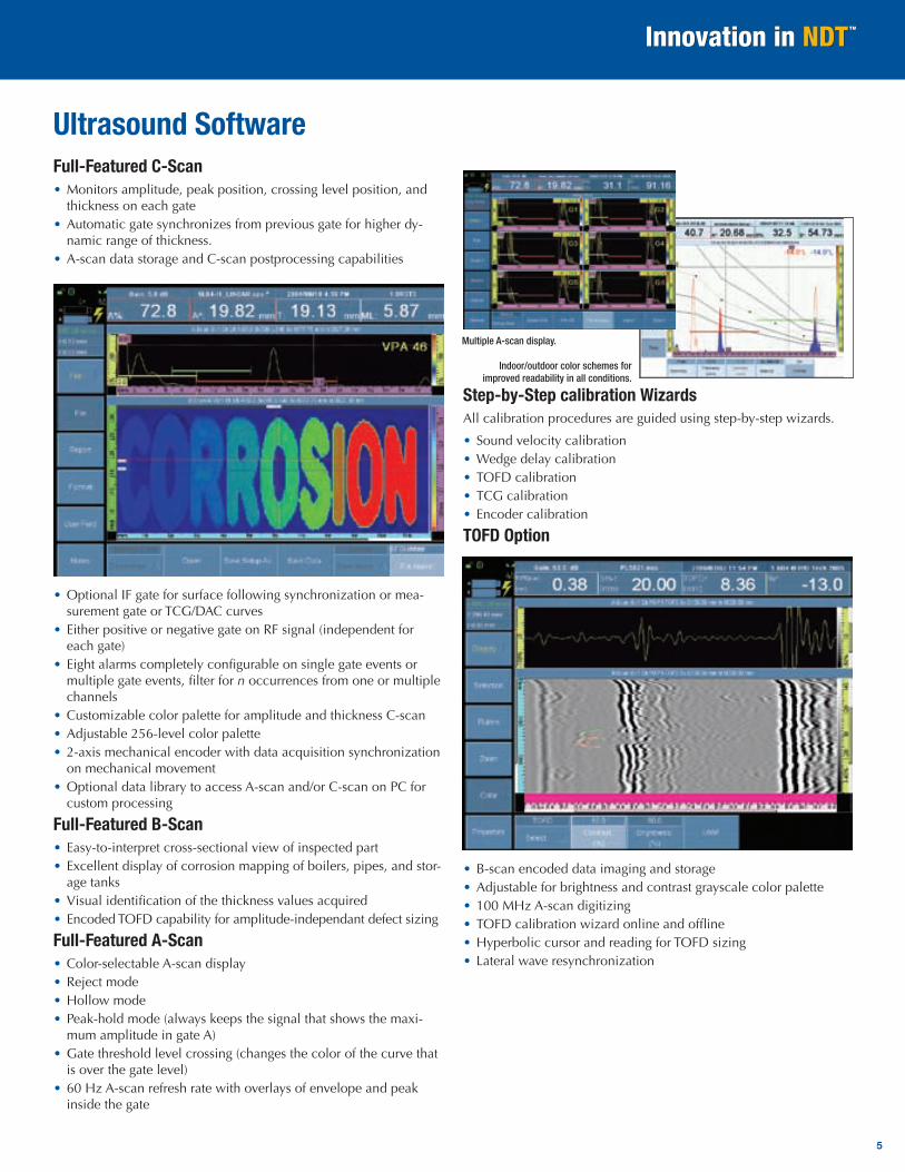
Ultrasound SoftwareFull-Featured C-Scan• Monitors amplitude, peak position, crossing level position, and
thickness on each gate• Automatic gate synchronizes from previous gate for higher dy-
namic range of thickness.• A-scan data storage and C-scan postprocessing capabilities
• Optional IF gate for surface following synchronization or mea-surement gate or TCG/DAC curves
• Either positive or negative gate on RF signal (independent for each gate)
• Eight alarms completely configurable on single gate events or multiple gate events, filter for n occurrences from one or multiple channels
• Customizable color palette for amplitude and thickness C-scan• Adjustable 256-level color palette• 2-axis mechanical encoder with data acquisition synchronization
on mechanical movement• Optional data library to access A-scan and/or C-scan on PC for
custom processing
Full-Featured B-Scan• Easy-to-interpret cross-sectional view of inspected part• Excellent display of corrosion mapping of boilers, pipes, and stor-
age tanks• Visual identification of the thickness values acquired• Encoded TOFD capability for amplitude-independant defect sizing
Full-Featured A-Scan• Color-selectable A-scan display• Reject mode• Hollow mode• Peak-hold mode (always keeps the signal that shows the maxi-
mum amplitude in gate A)• Gate threshold level crossing (changes the color of the curve that
is over the gate level)• 60 Hz A-scan refresh rate with overlays of envelope and peak
inside the gate
Step-by-Step calibration WizardsAll calibration procedures are guided using step-by-step wizards.
• Sound velocity calibration• Wedge delay calibration• TOFD calibration• TCG calibration• Encoder calibration
TOFD Option
• B-scan encoded data imaging and storage• Adjustable for brightness and contrast grayscale color palette• 100 MHz A-scan digitizing• TOFD calibration wizard online and offline• Hyperbolic cursor and reading for TOFD sizing• Lateral wave resynchronization
5
Multiple A-scan display.
Indoor/outdoor color schemes for improved readability in all conditions.
Transmitting delays
Receiving delaysand sum
Probe elements
PulsesIncident wave front
Reflected wave front
Trigger
Flaw
Flaw
Echo signals
Emitting
Acquisition unit
Receiving
Phased array unit
3
4
2
1
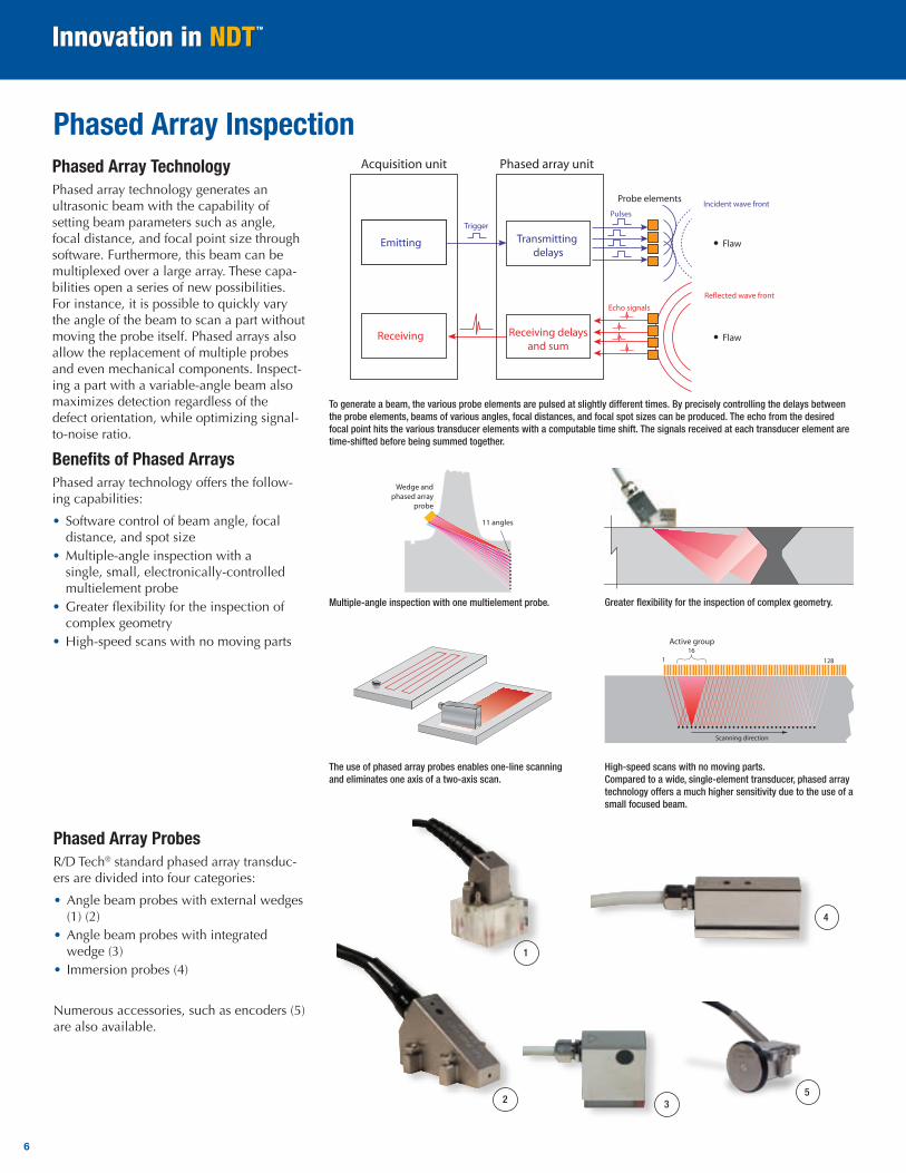
Phased Array ProbesR/D Tech® standard phased array transduc-ers are divided into four categories:
• Angle beam probes with external wedges (1) (2)
• Angle beam probes with integrated wedge (3)
• Immersion probes (4)
Numerous accessories, such as encoders (5) are also available.
Phased Array TechnologyPhased array technology generates an ultrasonic beam with the capability of setting beam parameters such as angle, focal distance, and focal point size through software. Furthermore, this beam can be multiplexed over a large array. These capa-bilities open a series of new possibilities. For instance, it is possible to quickly vary the angle of the beam to scan a part without moving the probe itself. Phased arrays also allow the replacement of multiple probes and even mechanical components. Inspect-ing a part with a variable-angle beam also maximizes detection regardless of the defect orientation, while optimizing signal-to-noise ratio.
Benefits of Phased ArraysPhased array technology offers the follow-ing capabilities:
• Software control of beam angle, focal distance, and spot size
• Multiple-angle inspection with a single, small, electronically-controlled multielement probe
• Greater flexibility for the inspection of complex geometry
• High-speed scans with no moving parts
Phased Array Inspection
The use of phased array probes enables one-line scanning and eliminates one axis of a two-axis scan.
Scanning direction
Active group
1281
16
11 angles
Wedge and phased array
probe
Multiple-angle inspection with one multielement probe. Greater flexibility for the inspection of complex geometry.
High-speed scans with no moving parts. Compared to a wide, single-element transducer, phased array technology offers a much higher sensitivity due to the use of a small focused beam.
To generate a beam, the various probe elements are pulsed at slightly different times. By precisely controlling the delays between the probe elements, beams of various angles, focal distances, and focal spot sizes can be produced. The echo from the desired focal point hits the various transducer elements with a computable time shift. The signals received at each transducer element are time-shifted before being summed together.
5
6
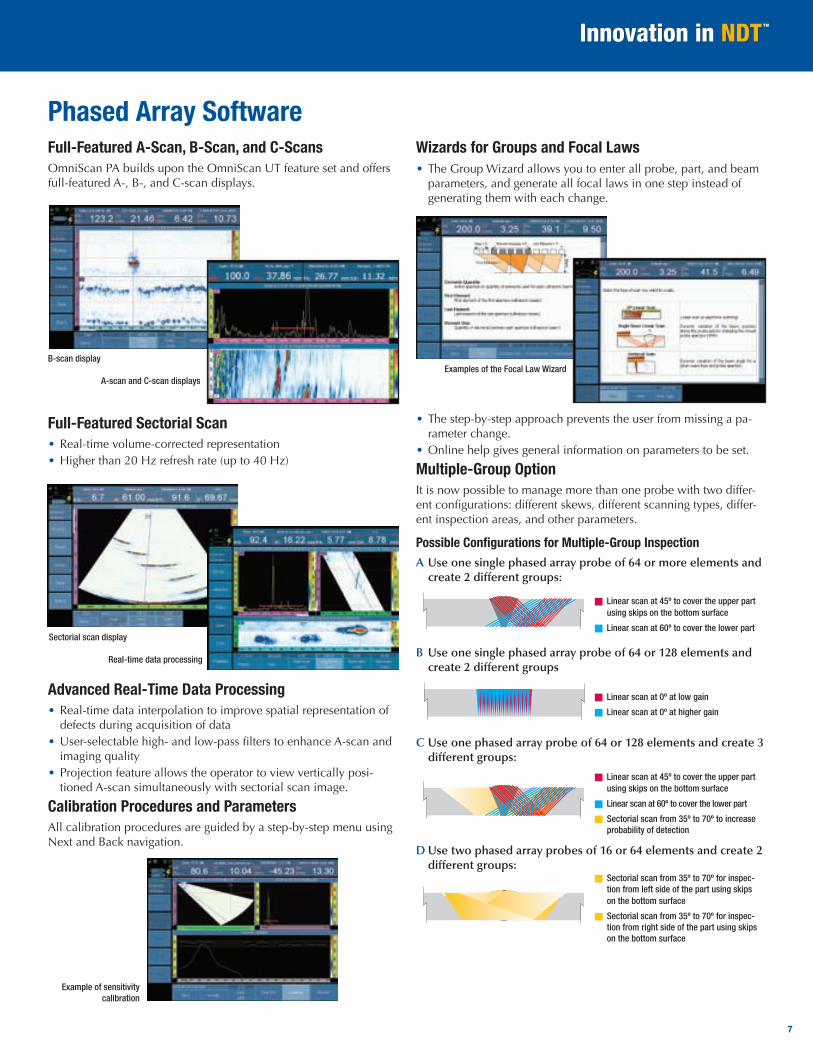
Phased Array SoftwareFull-Featured A-Scan, B-Scan, and C-ScansOmniScan PA builds upon the OmniScan UT feature set and offers full-featured A-, B-, and C-scan displays.
Full-Featured Sectorial Scan• Real-time volume-corrected representation• Higher than 20 Hz refresh rate (up to 40 Hz)
Advanced Real-Time Data Processing• Real-time data interpolation to improve spatial representation of
defects during acquisition of data• User-selectable high- and low-pass filters to enhance A-scan and
imaging quality• Projection feature allows the operator to view vertically posi-
tioned A-scan simultaneously with sectorial scan image.
Calibration Procedures and ParametersAll calibration procedures are guided by a step-by-step menu using Next and Back navigation.
Wizards for Groups and Focal Laws• The Group Wizard allows you to enter all probe, part, and beam
parameters, and generate all focal laws in one step instead of generating them with each change.
• The step-by-step approach prevents the user from missing a pa-rameter change.
• Online help gives general information on parameters to be set.
Multiple-Group OptionIt is now possible to manage more than one probe with two differ-ent configurations: different skews, different scanning types, differ-ent inspection areas, and other parameters.
Possible Configurations for Multiple-Group Inspection A Use one single phased array probe of 64 or more elements and
create 2 different groups:
Linear scan at 45º to cover the upper part using skips on the bottom surface
Linear scan at 60º to cover the lower part
B Use one single phased array probe of 64 or 128 elements and create 2 different groups
Linear scan at 0º at low gain
Linear scan at 0º at higher gain
C Use one phased array probe of 64 or 128 elements and create 3 different groups:
Linear scan at 45º to cover the upper part using skips on the bottom surface
Linear scan at 60º to cover the lower part
Sectorial scan from 35º to 70º to increase probability of detection
D Use two phased array probes of 16 or 64 elements and create 2 different groups:
Sectorial scan from 35º to 70º for inspec-tion from left side of the part using skips on the bottom surface
Sectorial scan from 35º to 70º for inspec-tion from right side of the part using skips on the bottom surface
7
Examples of the Focal Law Wizard
Sectorial scan display
Real-time data processing
B-scan display
A-scan and C-scan displays
Example of sensitivity calibration
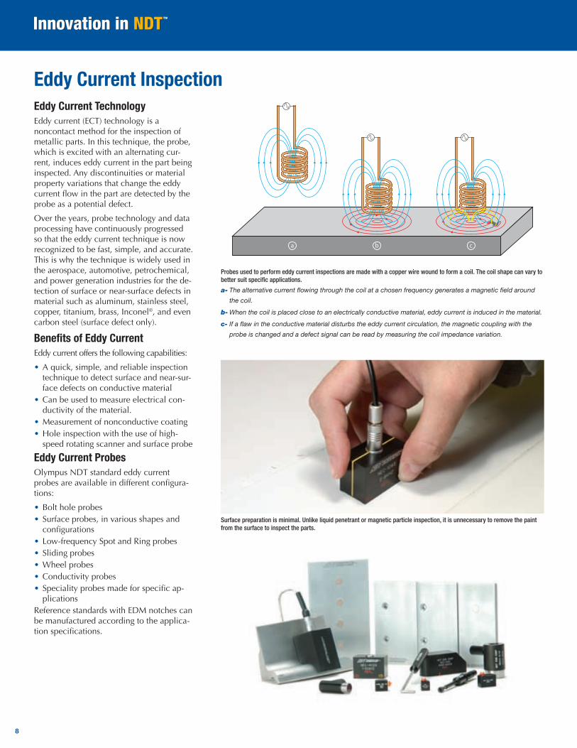
Eddy Current InspectionEddy Current TechnologyEddy current (ECT) technology is a noncontact method for the inspection of metallic parts. In this technique, the probe, which is excited with an alternating cur-rent, induces eddy current in the part being inspected. Any discontinuities or material property variations that change the eddy current flow in the part are detected by the probe as a potential defect.
Over the years, probe technology and data processing have continuously progressed so that the eddy current technique is now recognized to be fast, simple, and accurate. This is why the technique is widely used in the aerospace, automotive, petrochemical, and power generation industries for the de-tection of surface or near-surface defects in material such as aluminum, stainless steel, copper, titanium, brass, Inconel®, and even carbon steel (surface defect only).
Benefits of Eddy CurrentEddy current offers the following capabilities:
• A quick, simple, and reliable inspection technique to detect surface and near-sur-face defects on conductive material
• Can be used to measure electrical con-ductivity of the material.
• Measurement of nonconductive coating• Hole inspection with the use of high-
speed rotating scanner and surface probe
Eddy Current ProbesOlympus NDT standard eddy current probes are available in different configura-tions:
• Bolt hole probes• Surface probes, in various shapes and
configurations• Low-frequency Spot and Ring probes• Sliding probes• Wheel probes• Conductivity probes• Speciality probes made for specific ap-
plicationsReference standards with EDM notches can be manufactured according to the applica-tion specifications.
a b c
Probes used to perform eddy current inspections are made with a copper wire wound to form a coil. The coil shape can vary to better suit specific applications.
a-Thealternativecurrentflowingthroughthecoilatachosenfrequencygeneratesamagneticfieldaround
thecoil.
b-Whenthecoilisplacedclosetoanelectricallyconductivematerial,eddycurrentisinducedinthematerial.
c-Ifaflawintheconductivematerialdisturbstheeddycurrentcirculation,themagneticcouplingwiththe
probeischangedandadefectsignalcanbereadbymeasuringthecoilimpedancevariation.
Surface preparation is minimal. Unlike liquid penetrant or magnetic particle inspection, it is unnecessary to remove the paint from the surface to inspect the parts.
8
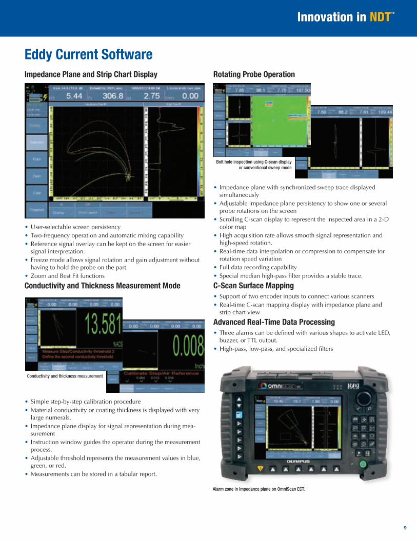
Eddy Current SoftwareImpedance Plane and Strip Chart Display
• User-selectable screen persistency• Two-frequency operation and automatic mixing capability• Reference signal overlay can be kept on the screen for easier
signal interpretation.• Freeze mode allows signal rotation and gain adjustment without
having to hold the probe on the part.• Zoom and Best Fit functions
Conductivity and Thickness Measurement Mode
• Simple step-by-step calibration procedure• Material conductivity or coating thickness is displayed with very
large numerals.• Impedance plane display for signal representation during mea-
surement• Instruction window guides the operator during the measurement
process.• Adjustable threshold represents the measurement values in blue,
green, or red.• Measurements can be stored in a tabular report.
Rotating Probe Operation
• Impedance plane with synchronized sweep trace displayed simultaneously
• Adjustable impedance plane persistency to show one or several probe rotations on the screen
• Scrolling C-scan display to represent the inspected area in a 2-D color map
• High acquisition rate allows smooth signal representation and high-speed rotation.
• Real-time data interpolation or compression to compensate for rotation speed variation
• Full data recording capability• Special median high-pass filter provides a stable trace.
C-Scan Surface Mapping• Support of two encoder inputs to connect various scanners• Real-time C-scan mapping display with impedance plane and
strip chart view
Advanced Real-Time Data Processing• Three alarms can be defined with various shapes to activate LED,
buzzer, or TTL output.• High-pass, low-pass, and specialized filters
Alarm zone in impedance plane on OmniScan ECT.
Conductivity and thickness measurement
Bolt hole inspection using C-scan display or conventional sweep mode
9
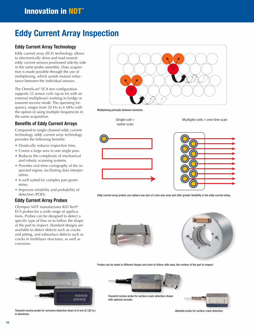
Eddy Current Array TechnologyEddy current array (ECA) technology allows to electronically drive and read several eddy current sensors positioned side-by-side in the same probe assembly. Data acquisi-tion is made possible through the use of multiplexing, which avoids mutual induc-tance between the individual sensors.
The OmniScan® ECA test configuration supports 32 sensor coils (up to 64 with an external multiplexer) working in bridge or transmit-receive mode. The operating fre-quency ranges from 20 Hz to 6 MHz with the option of using multiple frequencies in the same acquisition.
Benefits of Eddy Current ArraysCompared to single-channel eddy current technology, eddy current array technology provides the following benefits:
• Drastically reduces inspection time. • Covers a large area in one single pass.• Reduces the complexity of mechanical
and robotic scanning systems.• Provides real-time cartography of the in-
spected region, facilitating data interpre-tation.
• Is well suited for complex part geom-etries.
• Improves reliability and probability of detection (POD).
Eddy Current Array ProbesOlympus NDT manufactures R/D Tech® ECA probes for a wide range of applica-tions. Probes can be designed to detect a specific type of flaw or to follow the shape of the part to inspect. Standard designs are available to detect defects such as cracks and pitting, and subsurface defects such as cracks in multilayer structures, as well as corrosion.
Single coil = raster scan
Multiple coils = one-line scan
Eddy Current Array Inspection
Eddy current array probes can replace one axis of a two-axis scan and offer greater flexibility in the eddy current setup.
Transmit-receive probe for corrosion detection down to 6 mm (0.125 in.) in aluminum.
Multiplexing principle between elements.
Probes can be made in different shapes and sizes to follow, with ease, the contour of the part to inspect.
Absolute probe for surface crack detection.
Transmit-receive probe for surface-crack detection shown with optional encoder.
10
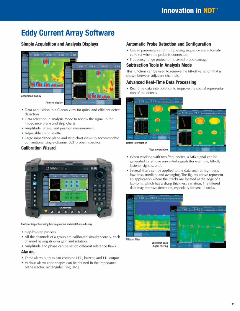
Simple Acquisition and Analysis Displays
• Data acquisition in a C-scan view for quick and efficient defect detection
• Data selection in analysis mode to review the signal in the impedance plane and strip charts
• Amplitude, phase, and position measurement• Adjustable color palette• Large impedance plane and strip chart views to accommodate
conventional single-channel ECT probe inspection
Calibration Wizard
• Step-by-step process• All the channels of a group are calibrated simultaneously, each
channel having its own gain and rotation.• Amplitude and phase can be set on different reference flaws.
Alarms• Three alarm outputs can combine LED, buzzer, and TTL output.• Various alarm zone shapes can be defined in the impedance
plane (sector, rectangular, ring, etc.).
Automatic Probe Detection and Configuration • C-scan parameters and multiplexing sequence are automati-
cally set when the probe is connected.• Frequency range protection to avoid probe damage
Subtraction Tools in Analysis ModeThis function can be used to remove the lift-off variation that is shown between adjacent channels.
Advanced Real-Time Data Processing• Real-time data interpolation to improve the spatial representa-
tion of the defects
• When working with two frequencies, a MIX signal can be generated to remove unwanted signals (for example, lift-off, fastener signals, etc.).
• Several filters can be applied to the data such as high-pass, low-pass, median, and averaging. The figures above represent an application where the cracks are located at the edge of a lap-joint, which has a sharp thickness variation. The filtered data may improve detection, especially for small cracks.
Eddy Current Array Software
11
Acquisition display
Analysis display
Fastener inspection using two frequencies and dual C-scan display.
Before interpolation
After interpolation
Without filterWith high-pass digital filtering
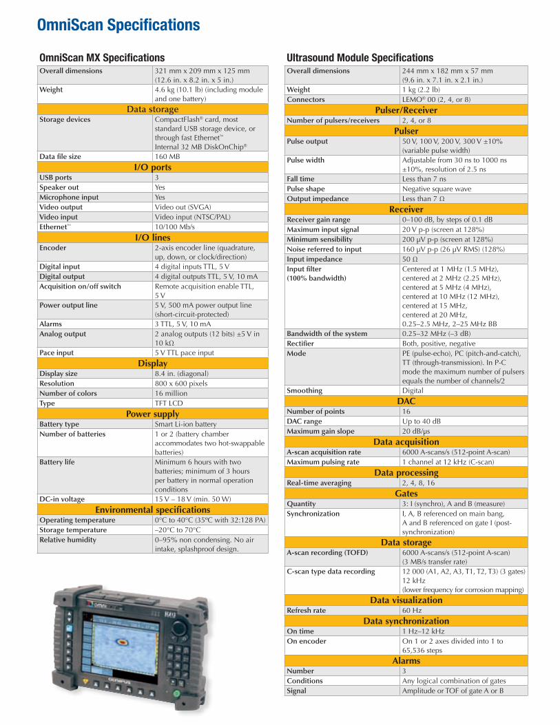
OmniScan MX SpecificationsOverall dimensions 321 mm x 209 mm x 125 mm
(12.6 in. x 8.2 in. x 5 in.)Weight 4.6 kg (10.1 lb) (including module
and one battery)
Data storageStorage devices CompactFlash® card, most
standard USB storage device, or through fast Ethernet™ Internal 32 MB DiskOnChip®
Data file size 160 MB
I/O portsUSB ports 3Speaker out YesMicrophone input YesVideo output Video out (SVGA)Video input Video input (NTSC/PAL)Ethernet™ 10/100 Mb/s
I/O linesEncoder 2-axis encoder line (quadrature,
up, down, or clock/direction)Digital input 4 digital inputs TTL, 5 VDigital output 4 digital outputs TTL, 5 V, 10 mAAcquisition on/off switch Remote acquisition enable TTL,
5 VPower output line 5 V, 500 mA power output line
(short-circuit-protected)Alarms 3 TTL, 5 V, 10 mAAnalog output 2 analog outputs (12 bits) ±5 V in
10 kΩPace input 5 V TTL pace input
DisplayDisplay size 8.4 in. (diagonal)Resolution 800 x 600 pixelsNumber of colors 16 millionType TFT LCD
Power supplyBattery type Smart Li-ion batteryNumber of batteries 1 or 2 (battery chamber
accommodates two hot-swappable batteries)
Battery life Minimum 6 hours with two batteries; minimum of 3 hours per battery in normal operation conditions
DC-in voltage 15 V – 18 V (min. 50 W)
Environmental specificationsOperating temperature 0°C to 40°C (35ºC with 32:128 PA)Storage temperature –20°C to 70°CRelative humidity 0–95% non condensing. No air
intake, splashproof design.
Ultrasound Module SpecificationsOverall dimensions 244 mm x 182 mm x 57 mm
(9.6 in. x 7.1 in. x 2.1 in.)Weight 1 kg (2.2 lb)Connectors LEMO® 00 (2, 4, or 8)
Pulser/ReceiverNumber of pulsers/receivers 2, 4, or 8
PulserPulse output 50 V, 100 V, 200 V, 300 V ±10%
(variable pulse width)Pulse width Adjustable from 30 ns to 1000 ns
±10%, resolution of 2.5 nsFall time Less than 7 nsPulse shape Negative square waveOutput impedance Less than 7 Ω
ReceiverReceiver gain range 0–100 dB, by steps of 0.1 dB Maximum input signal 20 V p-p (screen at 128%)Minimum sensibility 200 µV p-p (screen at 128%)Noise referred to input 160 µV p-p (26 µV RMS) (128%)Input impedance 50 ΩInput filter (100% bandwidth)
Centered at 1 MHz (1.5 MHz), centered at 2 MHz (2.25 MHz), centered at 5 MHz (4 MHz), centered at 10 MHz (12 MHz), centered at 15 MHz, centered at 20 MHz, 0.25–2.5 MHz, 2–25 MHz BB
Bandwidth of the system 0.25–32 MHz (–3 dB)Rectifier Both, positive, negativeMode PE (pulse-echo), PC (pitch-and-catch),
TT (through-transmission). In P-C mode the maximum number of pulsers equals the number of channels/2
Smoothing Digital
DACNumber of points 16DAC range Up to 40 dBMaximum gain slope 20 dB/µs
Data acquisitionA-scan acquisition rate 6000 A-scans/s (512-point A-scan)Maximum pulsing rate 1 channel at 12 kHz (C-scan)
Data processingReal-time averaging 2, 4, 8, 16
GatesQuantity 3: I (synchro), A and B (measure)Synchronization I, A, B referenced on main bang,
A and B referenced on gate I (post-synchronization)
Data storageA-scan recording (TOFD) 6000 A-scans/s (512-point A-scan)
(3 MB/s transfer rate)C-scan type data recording 12 000 (A1, A2, A3, T1, T2, T3) (3 gates)
12 kHz (lower frequency for corrosion mapping)
Data visualizationRefresh rate 60 Hz
Data synchronizationOn time 1 Hz–12 kHzOn encoder On 1 or 2 axes divided into 1 to
65,536 steps
AlarmsNumber 3Conditions Any logical combination of gatesSignal Amplitude or TOF of gate A or B
OmniScan Specifications
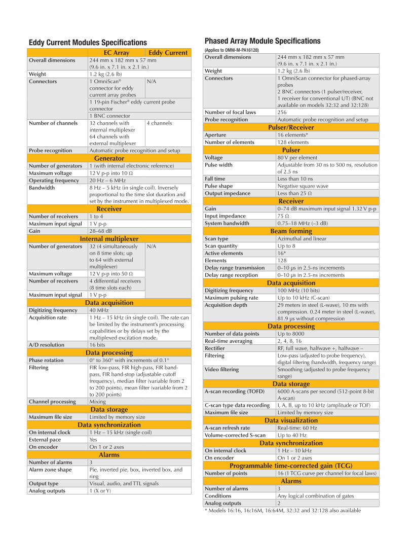
Phased Array Module Specifications(Applies to OMNI-M-PA16128)
Overall dimensions 244 mm x 182 mm x 57 mm (9.6 in. x 7.1 in. x 2.1 in.)
Weight 1.2 kg (2.6 lb)Connectors 1 OmniScan connector for phased-array
probes 2 BNC connectors (1 pulser/receiver, 1 receiver for conventional UT) (BNC not available on models 32:32 and 32:128)
Number of focal laws 256Probe recognition Automatic probe recognition and setup
Pulser/ReceiverAperture 16 elements*Number of elements 128 elements
PulserVoltage 80 V per elementPulse width Adjustable from 30 ns to 500 ns, resolution
of 2.5 nsFall time Less than 10 nsPulse shape Negative square waveOutput impedance Less than 25 Ω
ReceiverGain 0–74 dB maximum input signal 1.32 V p-pInput impedance 75 ΩSystem bandwidth 0.75–18 MHz (–3 dB)
Beam formingScan type Azimuthal and linearScan quantity Up to 8Active elements 16*Elements 128Delay range transmission 0–10 µs in 2.5-ns incrementsDelay range reception 0–10 µs in 2.5-ns increments
Data acquisitionDigitizing frequency 100 MHz (10 bits)Maximum pulsing rate Up to 10 kHz (C-scan)Acquisition depth 29 meters in steel (L-wave), 10 ms with
compression. 0.24 meter in steel (L-wave), 81.9 µs without compression
Data processingNumber of data points Up to 8000Real-time averaging 2, 4, 8, 16Rectifier RF, full wave, halfwave +, halfwave –Filtering Low-pass (adjusted to probe frequency),
digital filtering (bandwidth, frequency range)Video filtering Smoothing (adjusted to probe frequency
range)
Data storageA-scan recording (TOFD) 6000 A-scans per second (512-point 8-bit
A-scan) C-scan type data recording I, A, B, up to 10 kHz (amplitude or TOF)Maximum file size Limited by memory size
Data visualizationA-scan refresh rate Real-time: 60 HzVolume-corrected S-scan Up to 40 Hz
Data synchronizationOn internal clock 1 Hz – 10 kHzOn encoder On 1 or 2 axes
Programmable time-corrected gain (TCG)Number of points 16 (1 TCG curve per channel for focal laws)
AlarmsNumber of alarms 3Conditions Any logical combination of gatesAnalog outputs 2* Models 16:16, 16:16M, 16:64M, 32:32 and 32:128 also available
Eddy Current Modules SpecificationsEC Array Eddy Current
Overall dimensions 244 mm x 182 mm x 57 mm (9.6 in. x 7.1 in. x 2.1 in.)
Weight 1.2 kg (2.6 lb)Connectors 1 OmniScan®
connector for eddy current array probes
N/A
1 19-pin Fischer® eddy current probe connector1 BNC connector
Number of channels 32 channels with internal multiplexer 64 channels with external multiplexer
4 channels
Probe recognition Automatic probe recognition and setup
GeneratorNumber of generators 1 (with internal electronic reference)Maximum voltage 12 V p-p into 10 ΩOperating frequency 20 Hz – 6 MHzBandwidth 8 Hz – 5 kHz (in single coil). Inversely
proportional to the time slot duration and set by the instrument in multiplexed mode.
ReceiverNumber of receivers 1 to 4Maximum input signal 1 V p-pGain 28–68 dB
Internal multiplexerNumber of generators 32 (4 simultaneously
on 8 time slots; up to 64 with external multiplexer)
N/A
Maximum voltage 12 V p-p into 50 ΩNumber of receivers 4 differential receivers
(8 time slots each)Maximum input signal 1 V p-p
Data acquisitionDigitizing frequency 40 MHzAcquisition rate 1 Hz – 15 kHz (in single coil). The rate can
be limited by the instrument’s processing capabilities or by delays set by the multiplexed excitation mode.
A/D resolution 16 bits
Data processingPhase rotation 0° to 360° with increments of 0.1°Filtering FIR low-pass, FIR high-pass, FIR band-
pass, FIR band-stop (adjustable cutoff frequency), median filter (variable from 2 to 200 points), mean filter (variable from 2 to 200 points)
Channel processing Mixing
Data storageMaximum file size Limited by memory size
Data synchronizationOn internal clock 1 Hz – 15 kHz (single coil) External pace YesOn encoder On 1 or 2 axes
AlarmsNumber of alarms 3Alarm zone shape Pie, inverted pie, box, inverted box, and
ringOutput type Visual, audio, and TTL signalsAnalog outputs 1 (X or Y)
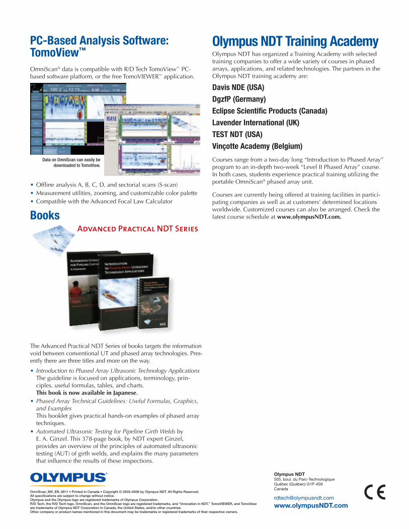
PC-Based Analysis Software: TomoView™
OmniScan® data is compatible with R/D Tech TomoView™ PC-based software platform, or the free TomoVIEWER™ application.
• Offline analysis A, B, C, D, and sectorial scans (S-scan)• Measurement utilities, zooming, and customizable color palette• Compatible with the Advanced Focal Law Calculator
Books
The Advanced Practical NDT Series of books targets the information void between conventional UT and phased array technologies. Pres-ently there are three titles and more on the way.
• Introduction to Phased Array Ultrasonic Technology Applications The guideline is focused on applications, terminology, prin-ciples, useful formulas, tables, and charts. This book is now available in Japanese.
• Phased Array Technical Guidelines: Useful Formulas, Graphics, and Examples This booklet gives practical hands-on examples of phased array techniques.
• Automated Ultrasonic Testing for Pipeline Girth Welds by E. A. Ginzel. This 378-page book, by NDT expert Ginzel, provides an overview of the principles of automated ultrasonic testing (AUT) of girth welds, and explains the many parameters that influence the results of these inspections.
Olympus NDT Training AcademyOlympus NDT has organized a Training Academy with selected training companies to offer a wide variety of courses in phased arrays, applications, and related technologies. The partners in the Olympus NDT training academy are:
Davis NDE (USA)DgzfP (Germany)Eclipse Scientific Products (Canada)Lavender International (UK)TEST NDT (USA)Vinçotte Academy (Belgium)
Courses range from a two-day long “Introduction to Phased Array” program to an in-depth two-week “Level II Phased Array” course. In both cases, students experience practical training utilizing the portable OmniScan® phased array unit.
Courses are currently being offered at training facilities in partici-pating companies as well as at customers’ determined locations worldwide. Customized courses can also be arranged. Check the latest course schedule at www.olympusNDT.com.
Olympus NDT505, boul. du Parc-TechnologiqueQuébec (Québec) G1P 4S9Canada
www.olympusNDT.com
OmniScan_MX_EN_0611 • Printed in Canada • Copyright © 2003–2006 by Olympus NDT. All Rights Reserved.All specifications are subject to change without notice.Olympus and the Olympus logo are registered trademarks of Olympus Corporation.R/D Tech, the R/D Tech logo, OmniScan, and the OmniScan logo are registered trademarks, and “Innovation in NDT,” TomoVIEWER, and TomoView are trademarks of Olympus NDT Corporation in Canada, the United States, and/or other countries.Other company or product names mentioned in this document may be trademarks or registered trademarks of their respective owners.
Data on OmniScan can easily be downloaded to TomoView.


![OmniScan MX and MX2 - ncontrol.ru · Оригинальная англоязычная версия: OmniScan MX and MX2 User’s Manual (DMTA-20015-01EN [U8778402] — редакция](https://img.dokumen.tips/doc/110x75/5b38c1d97f8b9a40428dcb5b/omniscan-mx-and-mx2-.jpg)

![OmniScan MX 和MX2 使用说明 … · DMTA-20015-01ZH [U8778425] — 版本H 2014 年1 月 OmniScan MX 和MX2 用户手册 这本指导手册包含安全有效地使用Olympus 产品的必要信息。](https://img.dokumen.tips/doc/110x75/5b5a3f7f7f8b9a24038c0796/omniscan-mx-dmta-20015-01zh-u8778425-h-2014-1.jpg)