Embed Size (px)
Citation preview

jk“Vªh; fÓyk ;kaf=dh laLÉku
(An Autonomous Research Institute under Ministry of Mines, Govt. of India) ¼Âku ea=ky;] Òkjr ljdkj] ds vÌhuLÉ ,d Lok;Ùk vuqlaÌku laLÉku½
ISO 9001:2000 Certified ¼ÁÃ-,l-Ás-9001%2000 lR;kfir½
P.O. - Champion Reefs Kolar Gold Fields -563117
Karnataka, India
i¨LV & PkSfEi;u jh¶l d¨ykj x¨YM QhYMl µ 563117
dukZVd] Òkjr
ANNUAL REPORT okfÔ Zd çfrosnu
2006-07

Quality Objectives Ø To become a global R&D organisation providing high quality,
need based, value added services in the emerging areas of rock engineering and rock mechanics for mining, excavation engineering and allied industries for improving production and safety.
Ø To develop innovative technologies and retain them through
intellectual property rights. Ø To disseminate the research and expertise through publication of
papers in national and international journals and seminars. Ø To develop human resources through training and workshops.
Quality Policy
NIRM is committed –
1. To achieve high quality R&D work and to provide services to the total satisfaction of customers with strict adherence to contractual specifications.
2. To register sustainable growth by conducting widely
acknowledged research in the areas of rock engineering to make NIRM a global center of excellence.
3. To enhance the knowledge and skill of the employees
through self development on continuous basis.
“NIRM is committed to comply with ISO 9001:2000 and to continually improve the Quality Management System”.
Annual Report 2006–07
1
okfÔ Zd çfrosnu 2006 µ07
ANNUAL REPORT 2006-07
(An ISO 9001: 2000 Certified Research Institute)
jk“Vªh; fÓyk ;kaf=dh laLÉku
National Institute of Rock Mechanics (An Autonomous Research Institute under Ministry of Mines, Govt. of India)
CHAMPION REEFS KOLAR GOLD FIELDS - 563 117
Karnataka, India

Annual Report 2006–07
2
Compiled by Dr P C Jha Published by : Technical Services Dept, NIRM ------------------------------------------------------------------------------------------------------- Front cover : In-situ seismic tomogram across Teesta River, Sikkim
Back cover : Earthquakes recorded by broad-band station at NIRM
Annual Report 2006–07
3
Contents Page no.
Page No.
Director's Report 4
Supporting Organizations / Clientele 7
1 In-situ Testing for Geotechnical Parameters 8
2 Ground Control Investigations in Mines & Excavations 13
3 Engineering Geophysical Investigations 21
4 Rock Fracture Mechanics and Material Testing 25
5 Numerical Modelling and Stability Analysis 28
6 Rock Excavation and Blasting 32
7 Dimension Stone Technology 36
8 Seismology and Micro-seismic Monitoring 41
9 Environmental Geotechnology 43
10 Technical Services 46
11 Annual Accounts 48
ANNEXURE 61-75
Appendix-1 Organization Chart of NIRM 62
Appendix-2 Members of the General Body 63
Appendix-3 Members of the Governing Body 65
Appendix-4 Members of the Peer Review Committee 67
Appendix-5 List of Projects 68
Appendix-6 List of Research Papers 71
Appendix-7 News Letter 73
Appendix-8 Distinguished Visitors to the Institute 74
Appendix-9 Staff of NIRM 75
Annual Report 2006–07
4
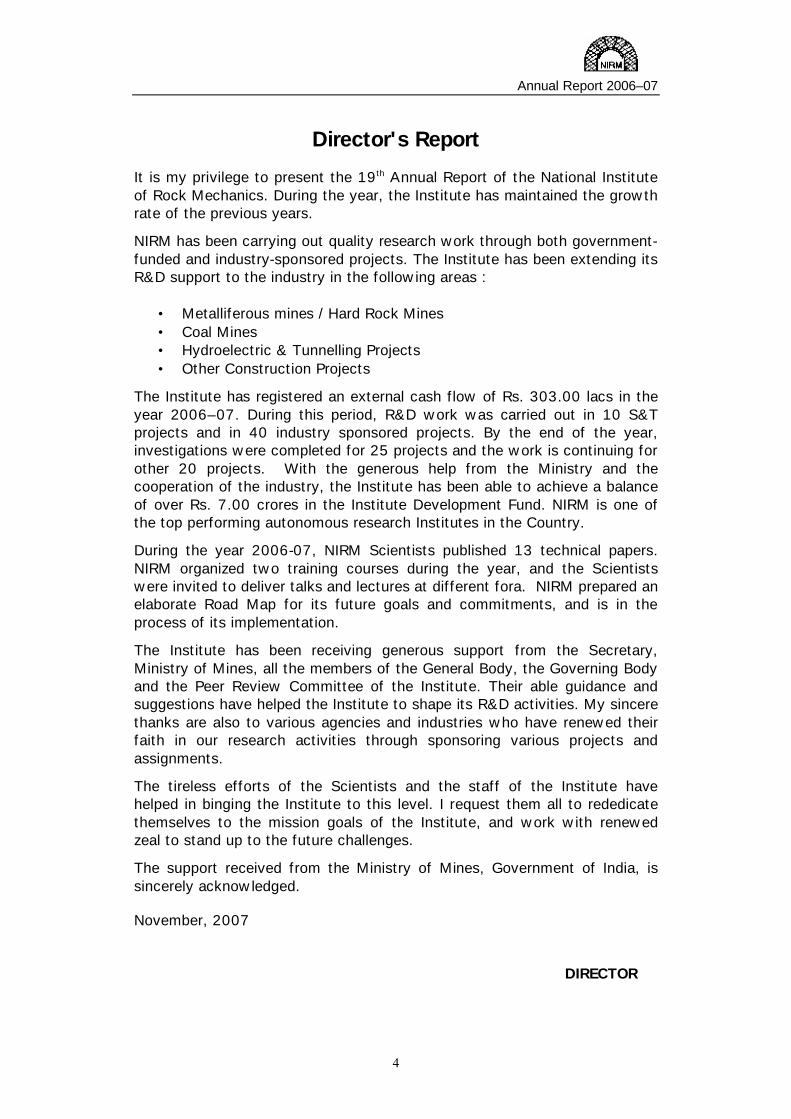
Director's Report It is my privilege to present the 19th Annual Report of the National Institute of Rock Mechanics. During the year, the Institute has maintained the growth rate of the previous years.
NIRM has been carrying out quality research work through both government-funded and industry-sponsored projects. The Institute has been extending its R&D support to the industry in the following areas :
• Metalliferous mines / Hard Rock Mines • Coal Mines • Hydroelectric & Tunnelling Projects • Other Construction Projects
The Institute has registered an external cash flow of Rs. 303.00 lacs in the year 2006–07. During this period, R&D work was carried out in 10 S&T projects and in 40 industry sponsored projects. By the end of the year, investigations were completed for 25 projects and the work is continuing for other 20 projects. With the generous help from the Ministry and the cooperation of the industry, the Institute has been able to achieve a balance of over Rs. 7.00 crores in the Institute Development Fund. NIRM is one of the top performing autonomous research Institutes in the Country.
During the year 2006-07, NIRM Scientists published 13 technical papers. NIRM organized two training courses during the year, and the Scientists were invited to deliver talks and lectures at different fora. NIRM prepared an elaborate Road Map for its future goals and commitments, and is in the process of its implementation.
The Institute has been receiving generous support from the Secretary, Ministry of Mines, all the members of the General Body, the Governing Body and the Peer Review Committee of the Institute. Their able guidance and suggestions have helped the Institute to shape its R&D activities. My sincere thanks are also to various agencies and industries who have renewed their faith in our research activities through sponsoring various projects and assignments.
The tireless efforts of the Scientists and the staff of the Institute have helped in binging the Institute to this level. I request them all to rededicate themselves to the mission goals of the Institute, and work with renewed zeal to stand up to the future challenges.
The support received from the Ministry of Mines, Government of India, is sincerely acknowledged.
November, 2007
DIRECTOR

Annual Report 2006–07
5
No. of Projects & Research Papers
Staff Strength
0
10
20
30
40
50
60
2001-02 2002-03 2003-04 2004-05 2005-06 2006-07
Projects completed Research papers publsihed
0
10
20
30
40
50
60
70
2001-02 2002-03 2003-04 2004-05 2005-06 2006-07
Scientists Total strength
Annual Report 2006–07
6
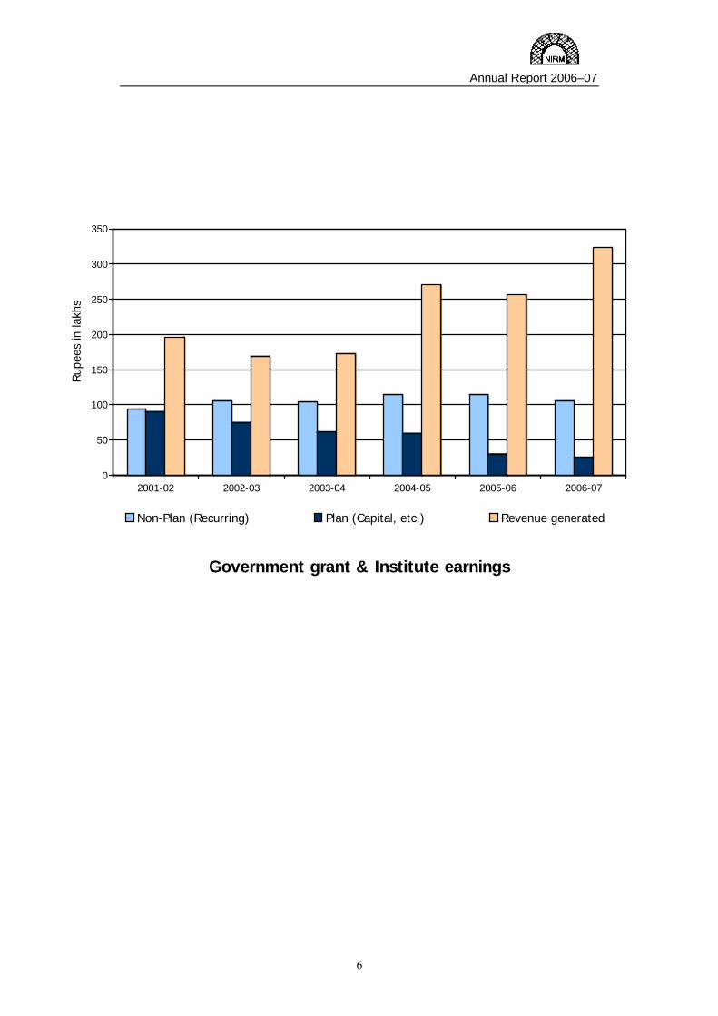
Government grant & Institute earnings
0
50
100
150
200
250
300
350
Rupe
es in
lakh
s
2001-02 2002-03 2003-04 2004-05 2005-06 2006-07
Non-Plan (Recurring) Plan (Capital, etc.) Revenue generated

Annual Report 2006–07
7
Supporting Organizations / Clientele Central Government Ministries & Departments
Dept of Science & Technology, Government of India Ministry of Coal, Government of India Ministry of Mines, Government of India Ministry of Water Resources, Government of India
State Government / Public Sector Organizations
Himachal Pradesh State Electricity Board (HPSEB) Kerala State Electricity Board (KSEB) Konkan Railway Corporation Ltd (KRCL) National Thermal Power Corporation Ltd (NTPC) Rail India Technical & Engineering Services (RITES) Sardar Sarovar Narmada Nigam Ltd (SSNNL) Satluj Jal Vidyut Nigam Ltd (SJVNL) Uttaranchal Jal Vidyut Nigam Ltdl (UJVNL)
Centre for Development of Stones (CDOS) Hindustan Zinc Limited (HZL) Hutti Gold Mines Ltd (HGML) National Aluminium Company Ltd (NALCO) Singareni Collieries Company Ltd (SCCL) Western Coalfields Ltd (WCL)
Private Companies
Bhoruka Power Corporation Ltd (BPCL) Carborundum Universal Limited (CUL) Ferro-Alloys Corporation, Orissa (FACOR) Larsen-Toubro – Ramboll Consulting Engineers Ltd (L&T-Ramboll) Murdeshwar Power Corporation Ltd. (MPCL) PRP Granites, Sivakasi, Tamil Nadu Satyam Sankarnarayan Joint Venture (SSJV)
International Organizations
Geo-Stock, France Italian-Thai Development Public Co Ltd (ITDL) Larsen-Toubro Oman Ltd (L&T-Oman) Tala Hydro Power Authority, Bhutan (THPA) United Nations Industrial Development Organization (UNIDO)

Annual Report 2006–07
8
In-situ Testing for Geotechnical Parameters (Dr. S.Sengupta, D.S.Subrahmanyam, R.K.Sinha, D.Joseph and Dr. V.P. Mishra)
Geotechnical investigations are an essential and integral part of any civil and mining engineering project. All the major projects where rock excavation is involved, particularly with the increase in the size and complexity of rock structures, require in-situ geotechnical investigations prior to design. The emergence of highly specialized computer modeling codes also call for reliable rock mass properties. The areas of services include: dam foundation, tunnel construction, cavern construction, underground and open cast mining, and slope stabilization. 1.1 Determination of in-situ parameters at Punatsangchhu hydroelectric project (S. Sengupta, D. S. Subrahmanyam, R. K. Sinha, D. Joseph and V. P. Mishra) Objectives :
• In-situ deformability parameters by plate loading method at the proposed dam axis for the design of dam
• In-situ deformability parameters by Goodmanjack method and in-situ stress by hydrofrac method at the proposed location of sedimentation chamber for the optimum orientation of sedimentation chamber vis a vis stress and also for the design of sedimentation chamber
• In-situ deformability parameters by Goodmanjack method and in-situ stress by hydrofrac method at the
proposed location of powerhouse chamber for optimum orientation of powerhouse chamber vis a vis stress and also for the design of powerhouse chamber
The Punatsangchhu Hydroelectric Project is located around 16 km from Lobeysa village in Wangdue Phodarang district and nearly 200 km from Phuentshillong town of Bhutan on the river Punatsangchhu. The project envisages construction of a solid straight concrete gravity dam of 137m height on river Punatsangchhu, an intake and underground sedimentation chamber near the Dam, a 7.468 km long HRT and a powerhouse with an installed capacity of 1095 MW near the village called Ruchekha. For the optimum design of surface and underground structures of the project, in-situ investigations are required to be incorporated in the design estimations.
1
Annual Report 2006–07
9
The scope of different in-situ investigations was as follows:
i) Determination of in-situ deformability parameters by Plate load method inside the exploratory drifts of proposed dam axis
ii) Determination of in-situ deformability parameters by Goodmanjack method and in-situ stress by hydrofrac method inside 250m deep vertical hole drilled at the proposed location of sedimentation chamber.
iii) Determination of In-situ deformability parameters by Goodmanjack method and in-situ stress by hydrofrac method inside 300m deep vertical hole drilled at the proposed location of powerhouse chamber.
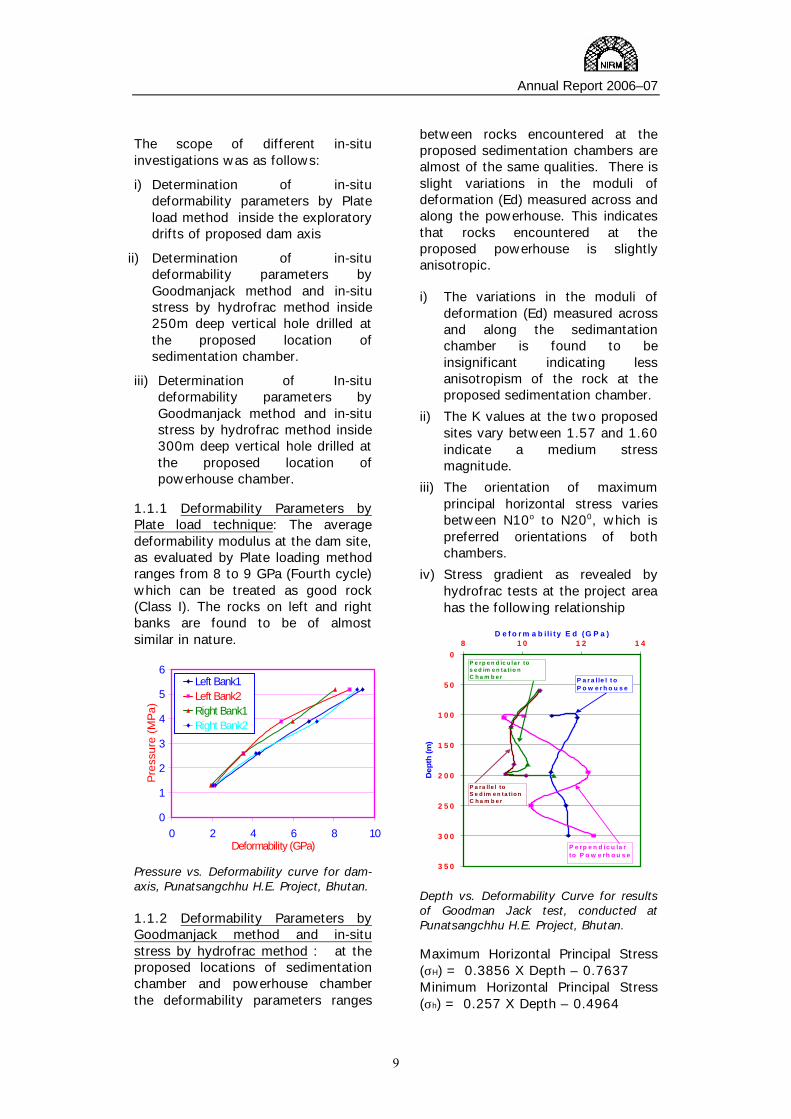
1.1.1 Deformability Parameters by Plate load technique: The average deformability modulus at the dam site, as evaluated by Plate loading method ranges from 8 to 9 GPa (Fourth cycle) which can be treated as good rock (Class I). The rocks on left and right banks are found to be of almost similar in nature.
0
1
2
3
4
5
6
0 2 4 6 8 10Deformability (GPa)
Pres
sure
(MPa
)
Left Bank1Left Bank2Right Bank1Right Bank2
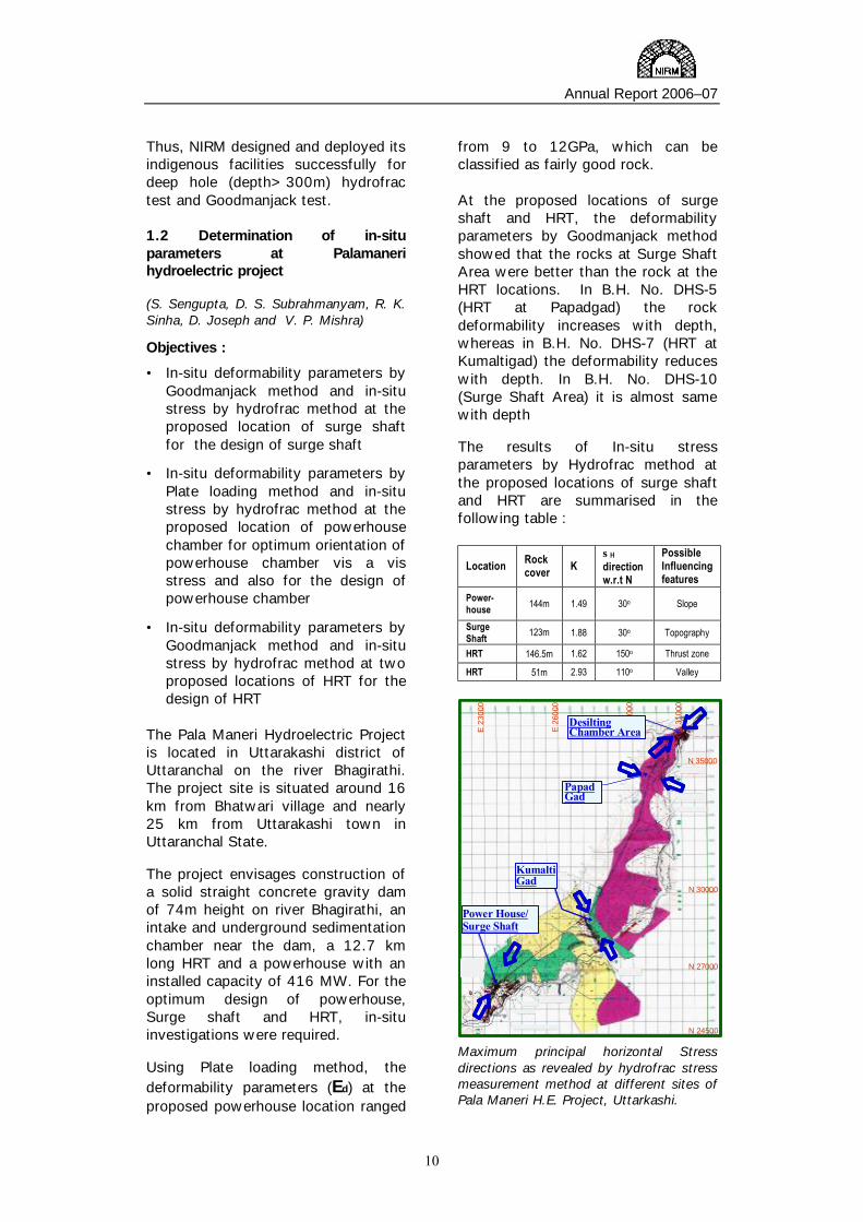
Pressure vs. Deformability curve for dam-axis, Punatsangchhu H.E. Project, Bhutan. 1.1.2 Deformability Parameters by Goodmanjack method and in-situ stress by hydrofrac method : at the proposed locations of sedimentation chamber and powerhouse chamber the deformability parameters ranges
between rocks encountered at the proposed sedimentation chambers are almost of the same qualities. There is slight variations in the moduli of deformation (Ed) measured across and along the powerhouse. This indicates that rocks encountered at the proposed powerhouse is slightly anisotropic. i) The variations in the moduli of
deformation (Ed) measured across and along the sedimantation chamber is found to be insignificant indicating less anisotropism of the rock at the proposed sedimentation chamber.
ii) The K values at the two proposed sites vary between 1.57 and 1.60 indicate a medium stress magnitude.
iii) The orientation of maximum principal horizontal stress varies between N10o to N200, which is preferred orientations of both chambers.
iv) Stress gradient as revealed by hydrofrac tests at the project area has the following relationship
0
5 0
1 0 0
1 5 0
2 0 0
2 5 0
3 0 0
3 5 0
8 1 0 1 2 1 4D e f o r m a b il i ty E d (G P a )
Dep
th (m
)
P a r a l le l t o P o w e r h o u s e
P e rp e n d ic u la r to P o w e rh o u s e
P a ra lle l to S e d im e n ta t io n C h a m b e r
P e rp e n d ic u la r to s e d im e n ta t io n C h a m b e r
Depth vs. Deformability Curve for results of Goodman Jack test, conducted at Punatsangchhu H.E. Project, Bhutan. Maximum Horizontal Principal Stress (σH) = 0.3856 X Depth – 0.7637 Minimum Horizontal Principal Stress (σh) = 0.257 X Depth – 0.4964
Annual Report 2006–07
10
Thus, NIRM designed and deployed its indigenous facilities successfully for deep hole (depth>300m) hydrofrac test and Goodmanjack test. 1.2 Determination of in-situ parameters at Palamaneri hydroelectric project (S. Sengupta, D. S. Subrahmanyam, R. K. Sinha, D. Joseph and V. P. Mishra)
Objectives :
• In-situ deformability parameters by Goodmanjack method and in-situ stress by hydrofrac method at the proposed location of surge shaft for the design of surge shaft
• In-situ deformability parameters by Plate loading method and in-situ stress by hydrofrac method at the proposed location of powerhouse chamber for optimum orientation of powerhouse chamber vis a vis stress and also for the design of powerhouse chamber
• In-situ deformability parameters by Goodmanjack method and in-situ stress by hydrofrac method at two proposed locations of HRT for the design of HRT
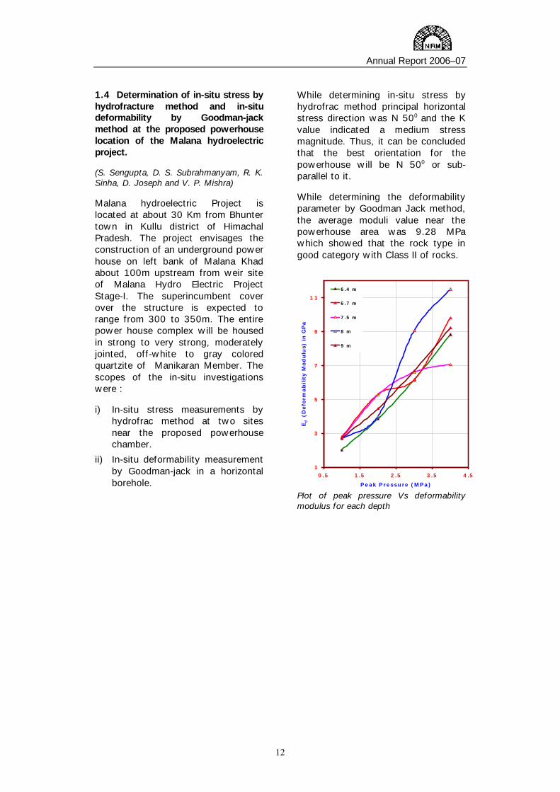
The Pala Maneri Hydroelectric Project is located in Uttarakashi district of Uttaranchal on the river Bhagirathi. The project site is situated around 16 km from Bhatwari village and nearly 25 km from Uttarakashi town in Uttaranchal State. The project envisages construction of a solid straight concrete gravity dam of 74m height on river Bhagirathi, an intake and underground sedimentation chamber near the dam, a 12.7 km long HRT and a powerhouse with an installed capacity of 416 MW. For the optimum design of powerhouse, Surge shaft and HRT, in-situ investigations were required. Using Plate loading method, the deformability parameters (Ed) at the proposed powerhouse location ranged
from 9 to 12GPa, which can be classified as fairly good rock. At the proposed locations of surge shaft and HRT, the deformability parameters by Goodmanjack method showed that the rocks at Surge Shaft Area were better than the rock at the HRT locations. In B.H. No. DHS-5 (HRT at Papadgad) the rock deformability increases with depth, whereas in B.H. No. DHS-7 (HRT at Kumaltigad) the deformability reduces with depth. In B.H. No. DHS-10 (Surge Shaft Area) it is almost same with depth The results of In-situ stress parameters by Hydrofrac method at the proposed locations of surge shaft and HRT are summarised in the following table :
Location Rock cover K
σH direction w.r.t N
Possible Influencing features
Power-house 144m 1.49 30o Slope
Surge Shaft 123m 1.88 30o Topography
HRT 146.5m 1.62 150o Thrust zone
HRT 51m 2.93 110o Valley
PapadGad
KumaltiGad
Power House/Surge Shaft
N 24500
N 27000
N 30000
N 35000
E 3
1000
E 2
9000
E 26
000
E 2
3000
DesiltingChamber Area
PapadGad
KumaltiGad
Power House/Surge Shaft
N 24500
N 27000
N 30000
N 35000
E 3
1000
E 2
9000
E 26
000
E 2
3000
DesiltingChamber Area
Maximum principal horizontal Stress directions as revealed by hydrofrac stress measurement method at different sites of Pala Maneri H.E. Project, Uttarkashi.

Annual Report 2006–07
11
(i) The maximum horizontal principal stress orientations at powerhouse and surge shaft sites are uniform though higher K value at surge shaft may be due to the influence of topography.
(ii) The maximum horizontal principal stress orientations are influenced at least at two places along the proposed HRT. At Kumaltigad the orientation is 150 o which is sub parallel to the thrust zone at the vicinity of the investigation site. At Papadgad the maximum horizontal principal stress is oriented sub-parallel to the valley where the borehole was drilled.
(iii) A high K value at one of the sites of HRT is due to the effect of the valley.
1.3 Determination of In-Situ Stress, Deformability and Shear Parameters at the Proposed Powerhouse Location, for Dibang multipurpose project (S. Sengupta, D. S. Subrahmanyam, R. K. Sinha, D. Joseph and V. P. Mishra) The Dibang Multipurpose Hydroelectric Project is located in Lower Dibang Valley of Arunachal Pradesh on the river Dibang. The project site is located around 50 km from Roing town in Arunachal Pradesh State. The nearest railhead for Roing is Tinsukia in Assam which is 113 km from Roing town. The project envisages construction of an underground powerhouse to house 12 units of turbines of 250 MW each from a solid straight concrete gravity dam of 300m height on river Dibang. It is proposed to generate 3000MW. The scope of the work was as follows. i) Determination of in-situ stress
parameters inside Nx size borehole at proposed powerhouse chamber
ii) Determination of in-situ deformability parameters inside the exploratory drift at proposed powerhouse chamber
iii) Determination of in-situ shear characteristics between rock to rock inside exploratory drift at proposed powerhouse chamber
In situ stress by hydrofracture method shows a K value of 1.42 which indicates a medium stress magnitude. The principal horizontal stress direction, orientation of maximum horizontal principal stress, major discontinuities and the proposed powerhouse are given below :
Orientation of the major foliation/joint
Orientation of maximum horizontal principal stress
Strike Perpendicular direction
Orientation of proposed
powerhouse
N 1500 N 470 – N 520
N 1370 - N 1420 N 1700
From the above table it can be concluded that the best orientation for the powerhouse will be N 1400 - N 1500 which is intersection of σH direction and perpendicular to the strike direction of the foliation/joint In the plate load test method, deformability modulus of the rock mass is on the lower side, which may be due to presence of rocks at saturated condition. The deformability parameters shows that the average moduli values at the powerhouse range from 3.2 GPa to 5.3 GPa which categorises the rock type in fair to good with III to II class. A low value of cohesion (shear parameter) was obtained, which may be attributed to the saturated condition prevailing over the test sites and presence of clay filled joints.
Annual Report 2006–07
12
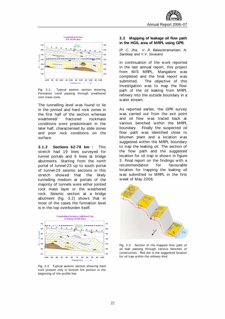
1.4 Determination of in-situ stress by hydrofracture method and in-situ deformability by Goodman-jack method at the proposed powerhouse location of the Malana hydroelectric project. (S. Sengupta, D. S. Subrahmanyam, R. K. Sinha, D. Joseph and V. P. Mishra) Malana hydroelectric Project is located at about 30 Km from Bhunter town in Kullu district of Himachal Pradesh. The project envisages the construction of an underground power house on left bank of Malana Khad about 100m upstream from weir site of Malana Hydro Electric Project Stage-I. The superincumbent cover over the structure is expected to range from 300 to 350m. The entire power house complex will be housed in strong to very strong, moderately jointed, off-white to gray colored quartzite of Manikaran Member. The scopes of the in-situ investigations were : i) In-situ stress measurements by
hydrofrac method at two sites near the proposed powerhouse chamber.
ii) In-situ deformability measurement by Goodman-jack in a horizontal borehole.
While determining in-situ stress by hydrofrac method principal horizontal stress direction was N 500 and the K value indicated a medium stress magnitude. Thus, it can be concluded that the best orientation for the powerhouse will be N 500 or sub-parallel to it. While determining the deformability parameter by Goodman Jack method, the average moduli value near the powerhouse area was 9.28 MPa which showed that the rock type in good category with Class II of rocks.
1
3
5
7
9
11
0.5 1.5 2.5 3.5 4.5
Peak Pressure (MPa)
Ed
(D
efo
rmab
ilit
y M
od
ulu
s) in
GP
a
6.4 m
6.7 m
7.5 m
8 m
9 m
Plot of peak pressure Vs deformability modulus for each depth

Annual Report 2006–07
13
Ground Control Investigations in Mines & Excavations (V.Venkateswarlu, S.K.Mohanty, C.Nagaraj, Atul Gandhe, S.Benady and S.B.Mishra)
For the design of any excavation in the mining or civil engineering industry, it is essential to know the type and nature of the rock being dealt with. The first step in this direction is characterization of the rock mass, involving the application of appropriate rock mass classification systems. The Institute has expertise in mapping of discontinuities and large scale ground features in rock, and based on them to characterize the ground conditions, and design the support measures. The data generated also forms the basis for other stability analysis techniques.
2.1 GEOTECHNICAL INVESTIGATIONS (SK Mohanty & V Venkateswarlu)
NIRM conducts field investigations, including systematic joint mapping, as part of site characterization studies. The output from these studies formed the basis for design of underground excavations and surface structures.
The South Asia LPG Company Private Limited (SALPG) has been developing an LPG underground storage facility in the Visakhapatnam Port area, Andhra Pradesh. The LPG underground storage facilities will be used for storing and dispatching LPG received at a nearby jetty. The approximate depth of excavation is 190 m below sea level and the volume to be excavated is around 1,50,000 cu.m. One Scientist from NIRM has been stationed at the site for daily mapping of the ground conditions during the excavation of the shafts, tunnels and other openings. Geotechnical mapping
of the joints and other features is being carried out immediately after each blast. Rock support required in each zone is estimated, and the project authorities are advised on the support measures to be taken on daily basis. Geotechnical mapping was carried out at the following sites, and the support recommendations were made. The major rock type encountered in the shafts and galleries is the garnet gneiss (Khondalite) of Late Achaean to Early Proterozoic age formed during high-grade regional metamorphism. The gneissose banding consists of more or less regular alternation of light colored and dark colored bands differing in mineral composition. The light colored bands of gneiss are generally composed of quartz, feldspar and sillimanite, and dark colored bands of garnet, mica and/or amphiboles, etc. Garnet gneiss
2

Annual Report 2006–07
14
locally develops large clots or augens (German, "eyes") of coarse crystals.
LOCATION Date of
completion Excavated length (m)
Operation Shaft (top EL : -18.90)
21.03.06 178
Access Shaft (top EL : -12)
26.07.05 172
Water Curtain Gallery - Operation Shaft Connection
25.4.05 14.5
Water Curtain Gallery - Access Shaft Connection (WAC)
28.06.05 7.25
Water Curtain Gallery (WCG) (Northward) 08.11.05 194
Water Curtain Gallery (WCG) (Southward)
06.06.05 16
Upper Shaft Connection 27.09.05 12 Ramp – Cavern Upper Connection (Eastward)
28.02.06 32
Ramp – Cavern Upper Connection (Westward)
28.02.06 32
Ramp – Cavern Intermediate Connection (IC) (Eastward)
02.05.06 28
Ramp – Cavern Intermediate Connection (IC) (Westward)
18.04.06 28
Cavern Main Gallery (CMG) - 1
Feb., 2007 160
Cavern Main Gallery (CMG) - 2
Feb., 2007 160
CMG - OS Lower Connection (COLC)
28.02.06 14.4
CMG - OS Upper Connection (COUC)
11.01.06 31
Access Ramp (AR) 11.07.06 65.5
In general, the rock mass in the two shafts and the adjacent galleries was intersected by one to three prominent sets of joints, which were continuous and persistent, planar with sandy particles and non-softening mineral coatings. The rock mass was completely dry in nature, but it was locally damp at places.
The geological / geotechnical mapping was carried out after every drill & blast-mucking-scaling cycle. The petrological and petrographic nature of the rock matrix, details of the discontinuities were mapped and the data plotted on plans. The permanent support system was recommended based on rock mass classification system. The 3-D excavation mapping was submitted to SALPG on a daily basis in draft form and on a weekly basis in final form. The project was completed.
2.2 STRATA CONTROL IN COAL MINES
(V Venkateswarlu, Atul Gandhe, S Benady & SB Mishra)
India has more than 2500 Mt of coal locked up in underground pillars in different seams. Conventional methods of extraction lead to low production and productivity, and render large reserves of coal unworkable. Hence there is an urgent need to adopt innovative designs and technologies for the safe, economic and conservative exploitation of the precious energy source. Further, in several coal mines in India, the workings offer complex geo-mining environment, and pose a challenge for design of the supports. To tackle such and related problems, NIRM undertook several S&T projects and a number of industry-sponsored projects related to methods of work and design of suitable system of support. 2.2.1 Optimization of Pillar Dimensions in Steeply Inclined Seams
The Singareni Collieries Company Ltd. (SCCL) has recently added new reserves of coal in Bhoopalpalli Area, and opened several mines in seams dipping more than 1 in 2.5 (21.8o). As there was no mechanized system available for such steep gradients, it was planned to extract these reserves by bord and pillar method using manual loading. However, in view of the practical problems with basket loading in the steep gradients, NIRM, in collaboration with SCCL, initiated an S&T project in 1999 to optimize the design parameters for pillars in steeply inclined seams (Phase-I). This project has been funded by the Department of Coal, Government of India,
The site selected for the experimentation was Kakatiya Khani No. 5 (KTK-5) Incline in Bhoopalpalli Area. Based on numerical modeling, NIRM suggested rectangular pillars of size 10 m x 26 m. The development

Annual Report 2006–07
15
of the experimental panel started in April, 2005 (Phase-II). NIRM installed the required instruments, and conducted the strata monitoring work as the galleries were being developed. The strata monitoring till the end of the development phase indicated normal and stable strata conditions in the experimental panel. Therefore, it was recommended to take up the depillaring operations in the panel.
The de-pillaring operations in the panel commenced in November, 2006 (Phase-3 of the project). NIRM continued to monitor the strata behaviour and the performance of the supports during the pillar extraction in the experimental panel NW-1/3 through instrumentation monitoring. Nearly 50% of the pillars in the panel were extracted, and the area extracted till end of March, 2007 was 16500sq.m. The data from the instruments indicated normal strata conditions.
The roof strata above the seam was moderately cavable in nature; therefore, induced blasting was carried out periodically to help easy caving in the goaf. With this, regular falls had taken place in the goaf during the depillaring operations. Physical observation of the roof and sides in the panel indicated that the general ground conditions were satisfactory, and there was no significant disturbance or deterioration of the roof or the pillars anywhere.
2.2.2 Caveability of the Roof Strata in Longwall Panels
Longwall mining with caving is a very popular method of underground mining worldwide. This method has a high potential of production and productivity with safety and conservation. Unfortunately, major collapses/ failures were experienced in mechanized longwall faces in India such as at Churcha, SECL, in 1990 and Kottadih, ECL, in 1997. The overlying roof was found to be massive and difficult to cave, and the support resistance initially estimated was found inadequate to cope up with the caving of coal roof.
Therefore, understanding the caving behaviour of roof rocks is of prime necessity to decide on the support type and its capacity to achieve successful strata control in a longwall panel. Against this backdrop, the three major research institutions, CMRI, NIRM and ISM, came together and took up a major research programme, with an objective for development of an integrated approach for selection of the capacity of powered support and formulation of a strata and support behaviour monitoring scheme for longwall operation in Indian coal mines. This is an S&T project funded by the Department of Coal, Government of India. The project aims at analysing a few previously worked out and presently running longwall panels and studying the sequence and nature of caving of overlying rocks by numerical modelling techniques. Based on these, it is proposed to develop a suitable method for the assessment of caveability of overlying roof rocks.
Data related to past longwall panels was collected from GDK-9 incline, SCCL. Further data is being collected from other mines. As soon as the instruments are procured, specific longwall panels will be identified, and the instrumentation and monitoring

Annual Report 2006–07
16
work will be initiated. The project is continuing. 2.2.3 Introduction of Continuous Miner at VK-7 Incline, SCCL
At Venkatesh Khani No. 7 incline, Kothagudem Area, it was proposed to introduce the continuous miner in King seam to extract the developed pillars in panel no. CMP-1. Being a new technology, M/s Rock Mechanics Technology Ltd (RMT) of UK proposed the panel design. NIRM was associated along with M/s RMT in carrying out systematic strata monitoring studies during the extraction of pillars in the panel.
To monitor the behaviour of the strata during the extraction of the pillars in panel no. CMP-1, geotechnical instruments were installed by NIRM which included vibrating-wire type stress cells, pillar strain meters and extensometers, both magnetic-ring type and Tell-Tale type.
Three pillars were extracted in the panel during the first two months. Strata monitoring studies indicted a maximum abutment stress of 560 kPa on the first pillar during extraction. After extraction of the first pillar the abutment stresses were transferred to the adjacent pillars. The maximum stresses recorded in pillars adjacent to the pillar under extraction were 440 to 550 kPa. During the splitting of the pillar no. 3, there was a steep increase of 1200 kPa stress on the pillar on the rise side. The influence of pillar extraction by the continuous
miner was at least 50 m ahead of the pillar under extraction. The stresses were generally increasing during splitting in the adjacent pillars, and they decreased after induced blasting was carried out, which was accompanied by local falls. Up to 70 to 80% volume of the goaf was filled with the overlying sandstone muck fallen naturally or after induced blasting. The extensometer installed in the side of pillar no. 5 recorded 38 mm dilation up to 2 m inside from level side during extraction of pillar no. 1. The movement from the dip side in the same pillar was 22 mm during extraction of pillar no. 1, and 32 mm during extraction of pillar no. 3. This was attributed to the abutment stresses acting over the pillars due to increase in area of extraction.
The project work was suspended due to an accident in the mine.
2.2.4 Stability of Rhombus Shaped Pillars
Strata control problems are encountered at KTK-1 and 5 Inclines, particularly due to steep gradients. To negotiate the steep gradients, the development was carried out along apparent dip, forming rhombus shaped pillars and pillars with acute angled corners, whose stability needs to be studied. Similar problems are expected while developing no. 3 seam at KTK-8 Incline.
In view of this, NIRM has taken up a scientific study for addressing the

Annual Report 2006–07
17
entire issue. The stability of the rhombus shaped pillars in these mines will be estimated, and a proper method of extraction will be suggested. Systematic support rules will be formulated particularly for the corners in the junctions, during the development stage and for the depillaring operations. The project is continuing.
2.3 DESIGN OF SUPPORTS IN MINES
(V Venkateswarlu, Atul Gandhe & S Benady)
2.3.1 Design of supports for KTK-2, 3 & 6 Inclines, Bhupalpalli
Roof control problems are being experienced at KTK-2, KTK-3 and KTK-6 inclines of the Bhupalpalli area of SCCL. In view of this, studies were taken up to formulate the systematic support rules (SSR) for the development workings in all the three seams occurring at these three mines.
The strata at these mines are steeply dipping by 1 in 3 to 1 in 4. The stability of the galleries is affected due to the presence of varying thickness of clay bands in the working sections as well as in the roof sections, and abnormal water seepage. There are a number of slip planes in the roof. Due to the adverse ground conditions, in several cases, the mine management used roof supports with a high safety factor of 3. In view of this, studies are being conducted to recommend systematic support rules in the mine.
2.4 INSTRUMENTATION & MONITOR-ING
(V Venkateswarlu, C Nagaraj, Atul Gandhe, S Benady & SB Mishra)
Though established guidelines exist for the estimation of support requirement, the design needs to be verified based on systematic monitoring of the support behavior in response to the strata movements. NIRM undertakes strata and support monitoring on a routine basis, and has been involved in a large number of such projects. 2.4.1 Ground Stability in Hutti Gold Mines
The Hutti Gold Mines Limited extracts gold ore at Hutti gold mine in Raichur district of Karnataka state. In this mine there are four number of reefs in which mining is being done. To evaluate the ground stability in different stoping areas of the mine, NIRM installed a number of instruments in the crown pillar, the hanging wall, three rib pillars, the ore pillar and different hangwall/footwall cross cuts.
During the extraction of M6-2 and M7-1 open stopes, NIRM continued the monitoring using multi-point bore hole extensometers, stress cells and tape extensometer points. Based on these investigations, it was seen that the ground conditions in the LDBH stope blocks of GE-47 and 51 at Hutti gold mine are stable. The readings so far have not indicated any significant change in the stress, nor any strata movements. Further monitoring of the instruments is being continued to confirm the long-term stability of the workings. 2.4.2 Longwall Panels in Coal Mines
At GDK 10A incline, SCCL, extraction of coal by mechanized longwall method with powered supports has been completed in many panels. The

Annual Report 2006–07
18
roof in the longwall face is supported by 4 / 750 t Chock Shield type self advancing powered supports provided with extension bar to support the freshly exposed roof at the face. Panel No. 8 of the mine is under extraction. Strata control investigations were carried out by NIRM to monitor stress changes in the pillars, pressure changes on the powered supports, load on supports in the gate roads and associated displacements, with the help of geotechnical instrumentation and monitoring.
There was no significant influence of abutment loading even at the time of the main fall. All the chock shields, except a few in the middle, were lightly loaded, and there was no roof overhang or weighting exerted on the chocks. Maximum roof to floor convergence in the gate roads was 162 mm, with a maximum rate of convergence of 49 mm/day at 2 m ahead of the face prior to a roof fall in the goaf. Most of the roof sagging was within the immediate coal layers.
Vertical supports in the gate roads experienced a maximum change in load of 11 t within 5 m of the face. Maximum bed separation of 78 mm was recorded within 6 m of the face in the gate roads. Most of the movements were within 1 m of the immediate coal roof. Maximum change in stress over the barrier pillar was 7.6 kg/cm2 with a rate of change of stress of 2.7 kg/cm2/day. Extraction in the panel was successfully completed without any strata control problems.
The project is completed. 2.4.3 Blasting Gallery Panels in Coal Mines
At Venkatesh Khani 7 incline, Kothagudem Area, the King seam was developed in two sections with a parting of 2.5 m, and the full thickness is being extracted by
Blasting Gallery (BG) method in some of the panels. NIRM carried out strata monitoring studies during the extraction of BG panel no. 5 (Block-I & II). Earlier, Block-I of the panel was worked, and NIRM monitored the strata behaviour. Later NIRM carried out the instrumentation and strata monitoring in Block-II also.
The strata behaviour observations indicated that the roof movements, stress over the pillars, and load over the supports were more in Block-II as compared to those in Block-I. This may be attributed to the presence of overlying longwall barrier in the Queen seam. The average change in load over the hydraulic prop remained within 25 t which shows the efficacy of the support system in the galleries and junctions in the panel. On the whole, the extraction of the pillars by BG method in the experimental panel progressed smoothly without any strata control problems. The strata monitoring work in BG panel no. 5 at VK-7 was completed.
At No. 21 incline, Yellandu Area, the Queen seam was developed in two sections, and the full thickness of 9.5 m is being extracted by BG method. NIRM initiated strata monitoring studies in this mine, and installed various geotechnical instruments in panel no. 1.
The results of the strata behaviour observations indicated that the roof movements, stress over the pillars, and load over the supports were insignificant during the initial stages of extraction. Increase in the load over the hydraulic props was recorded only when the stations were within 5 m from the goaf edge. The maximum rate of change of convergence recorded was in general 2 mm/day. The stresses on the left out stooks of the overlying seam appear to have been transferred to the bottom seam workings causing deformation in the roof. No bed separation was recorded in the junctions during the extraction.

Annual Report 2006–07
19
Maximum stress over the pillars was in general 5.19 kg/cm2 with a rate of change of stress of 0.57 kg/cm2/day.
The extraction of the pillars in the panel no. 1 at 21 Incline has been still continuing.
2.4.4 Wide-stall Panels in Coal Mines
At Godavari Khani 8A incline, SCCL the top seam no. 1 was developed on bord and pillar method. Initially, the mine management worked the panel no. 47 on experimental basis by wide-stall method using SDLs. NIRM carried out strata monitoring in the panel to study the behaviour of the workings during the wide-stall extraction. No roof movements were recorded in the workings ahead of pillars under extraction, and no bed separation was recorded at the junctions during the monitoring period. Following the success of this, the adjacent panel (WS-2) was also worked out using the wide-stall method during which NIRM conducted studies on strata behaviour.
No roof movements were recorded in the workings ahead of pillars under extraction, and no bed separation was recorded at the junctions during the monitoring period in this panel also. This indicates the stability of the roof after widening and the efficacy of supports in the galleries and at the junctions.
The project is completed.
2.4.5 Conventional Bord & Pillar Depillaring Panels in Coal Mines
The SCCL has been mining coal by caving operations in a number of panels in different underground mines. To re-equip the confidence of the miners, NIRM undertook studies to monitor the roof behaviour by installing strata monitoring instruments during the depillaring operations in some of the mines
At GDK-5A incline, RG-1 Area, there are five working seams, namely, No. 1, 2, 3A, 3 and 4 seams, in descending order. In no. 1 seam, depillaring was carried out in several panels earlier by caving method. NIRM carried out strata monitoring on regular basis using geotechnical instruments during the depillaring operations.
The convergence measurements indicated no roof movement in the panel However, floor heaving up to a maximum of 88 mm was recorded in the galleries and at the junctions. No roof deformation was recorded at the junction by the borehole exten-someters. The load measurement indicated light loading near the goaf edges. The roof falls occurred at regular interval inside the goaf, which has been possible mainly due to the effective induced blasting of the immediate roof. Based on the strata monitoring studies carried out in the panel 31 and the physical observations, it is concluded that the extraction of pillars in the panel progressed smoothly without any strata control problems.
The project is completed.
2.4.6 Underground Excavations at Larji project, HPSEB
The Himachal Pradesh State Electricity Board (HPSEB) is constructing the Larji Hydro-Electric Project with a barrage over river Beas near Mandi in the Lower Himalayas, HP, to generate 126 MW electricity. The project consists of a number of excavations in rock, such as tunnels, shafts and large caverns. In view of the critical nature and long life of the excavations, HPSEB requested NIRM to investigate the rock behaviour.
With the data collected so far, it was seen that in the Desanding Chambers 2 and 4, some movements were recorded near the ramp at the top of the funnel portion. This was attributed to the comparatively weak rock mass

Annual Report 2006–07
20
in this area, for which additional supports using cable anchors and with complete concrete lining were provided.
In general, the measurements did not indicate any significant movements, deformations or loads in any of the excavations during the four years of the study. However, the observations have to be continued to confirm the long term stability of the excavations. To monitor all the instruments remotely, a data acquisition system was arranged. A central control room was set-up in the power house complex for monitoring the instruments even after the construction phase. The work in this project has been completed. 2.4.7 Preparation of Strata Monitoring Data Bank
A need was felt to compile all the available field data from different projects, and for different ground conditions. This work was taken up as an In-House S&T project by NIRM. The objective of the project was to develop a data bank of the strata monitoring results obtained for different ground conditions in mines, tunnels and caverns.
The project was basically a data collection and compilation work, and did not in itself involve any additional instrumentation or monitoring work. The work was completed.
2.4.8 Slope Stability Studies
Iron ore extraction is being carried out by opencast method at Subbarayanahally mine of the Mysore Minerals Ltd. (MML), in Sandur taluk, Bellary district, Karnataka. At present the maximum depth of working is 100 m. The mine management proposes to go further deeper by 90 m and until the ore body exhausts. For this
purpose, the mine management requested NIRM to study the stability of the pit slopes at the mine, and to suggest suitable design parameters.
For designing the ultimate angle of the pit slopes, it is proposed to carry out the analysis based on the limit equilibrium method using the software GALENA (developed by the BHP, Australia). The soil samples were collected from the mine and the physico-mechanical properties of the soil/rocks were determined at NIRM. These properties become the basic input parameters for the analysis.
The project is continuing.

Annual Report 2006–07
21
Engineering Geophysical Investigations
(P. C. Jha, V. R. Balasubramaniam, Sandeep Nelliat and Y. V. Sivaram)
Geophysical investigations are essential to supplement various rock mechanics investigations for site characterization. NIRM has established modern, sophisticated facilities in the area of Engineering Geophysics and the Institute is carrying out mapping of the subsurface using refraction, reflection, sounding and cross-hole tomographic techniques. We have a special high resolution and deeper penetration type of Ground Penetrating Radar (GPR), which can map subsurface details from 5 m to 70 m in ideal conditions, 2 sets of 24-channel digital seismographs to carry out seismic refraction, shallow seismic reflection studies and a 12-channel hydrophone assembly for cross-hole tomography.
3.1 Mapping subsurface stratigraphy at tunnel portals and bridge abutments using Seismic Refraction survey for Katra - Quazigund rail link project of Northern Railway (P. C. Jha, V. R. Balasubramaniam, N. Sandeep and Y.V. Sivaram)
The objective of the work was to delineate the stratigraphy up to a depth of 40m from the surface at tunnel portals, bridge abutments and important rail project locations falling between the 51-132 km section of the rail link alignment. This work was done for the 35km stretch between chainage 78-87, 101-110 and 62-78 km. This was the last leg of the geophysical survey work carried out under a comprehensive work order from RITES for the Katra-Quazigund rail link project. Seismic profiles were taken along two orthogonal lines at each portal reference point and bridge
abutment locations. The highlights of the survey result are enumerated below : 3.1.1 Sections 78 – 87 km & 101-110km : In this section of the alignment, 23 seismic lines were taken at the portals of five tunnels and 15 lines were surveyed at nine abutments. In addition, 3 lines were surveyed for the Kohli station yard. In total seismic survey in the 78-86km & 101-110km section was covered in 38 profile lines of 115m each being done by 24-channel digital seismograph at 5m interval of geophone array. The survey results reflected the presence of mostly jointed rock mass conditions at the formation (tunnelling) levels. A typical seismic section at the portal location is shown in Fig.3.1.
3
Annual Report 2006–07
22
Longitudinal Section(Ch. 83.426 Km)
Chainage in km
Portal Ref. point
RL
in m
etre
Soil
Weathered / fragmented Rock
Jointed Rock mass
Hard Rock
Formation Level
Fig. 3.1: Typical seismic section showing Formation Level passing through weathered rock mass zone. The tunnelling level was found to lie in the jointed and hard rock zones in the first half of the section whereas weathered/ fractured rockmass conditions were predominant in the later half, characterised by slide zones and poor rock conditions on the surface. 3.1.2 Sections 62-78 km : This stretch had 19 lines surveyed for tunnel portals and 9 lines at bridge abutments. Starting from the north portal of tunnel-23 up to south portal of tunnel-29 seismic sections in this stretch showed that the likely tunnelling medium at portals of the majority of tunnels were either jointed rock mass layer or the weathered rock. Seismic section at a bridge abutment (fig. 3.2) shows that in most of the cases the formation level is in the top overburden itself.
Longitudinal Section at Additional Line
(Chainage 65.040 Kms)
AbutmentRef. point
Soil
RL
in m
etre
Compact Soilwith rock fragments
Weathered / Fragmentedrock massHard Rock Jointed rock mass
Chainage in Km
Formation Level
Fig. 3.2: Typical seismic section showing hard rock present only in bottom 5m portion in the beginning of the profile line
3.2 Mapping of leakage oil flow path in the HGIL area of MRPL using GPR.
(P. C. Jha, V. R. Balasubramaniam, N. Sandeep and Y.V. Sivaram) In continuation of the work reported in the last annual report, this project from M/S MRPL, Mangalore was completed and the final report was submitted. The objective of this investigation was to map the flow path of the oil leaking from MRPL refinery into the outside boundary in a water stream. As reported earlier, the GPR survey was carried out from the exit point and oil flow was traced back at various benched within the MRPL boundary. Finally the suspected oil flow path was identified close to bitumen plant and a location was suggested within the MRPL boundary to trap the leaking oil. The section of the flow path and the suggested location for oil trap is shown in figure 3. Final report on the findings with a recommendation for favourable location for trapping the leaking oil was submitted to MRPL in the first week of May 2006.
Fig. 3.3: Section of the mapped flow path of oil leak passing through various benches of construction. Red dot is the suggested location for oil trap within the refinery limit.
Annual Report 2006–07
23
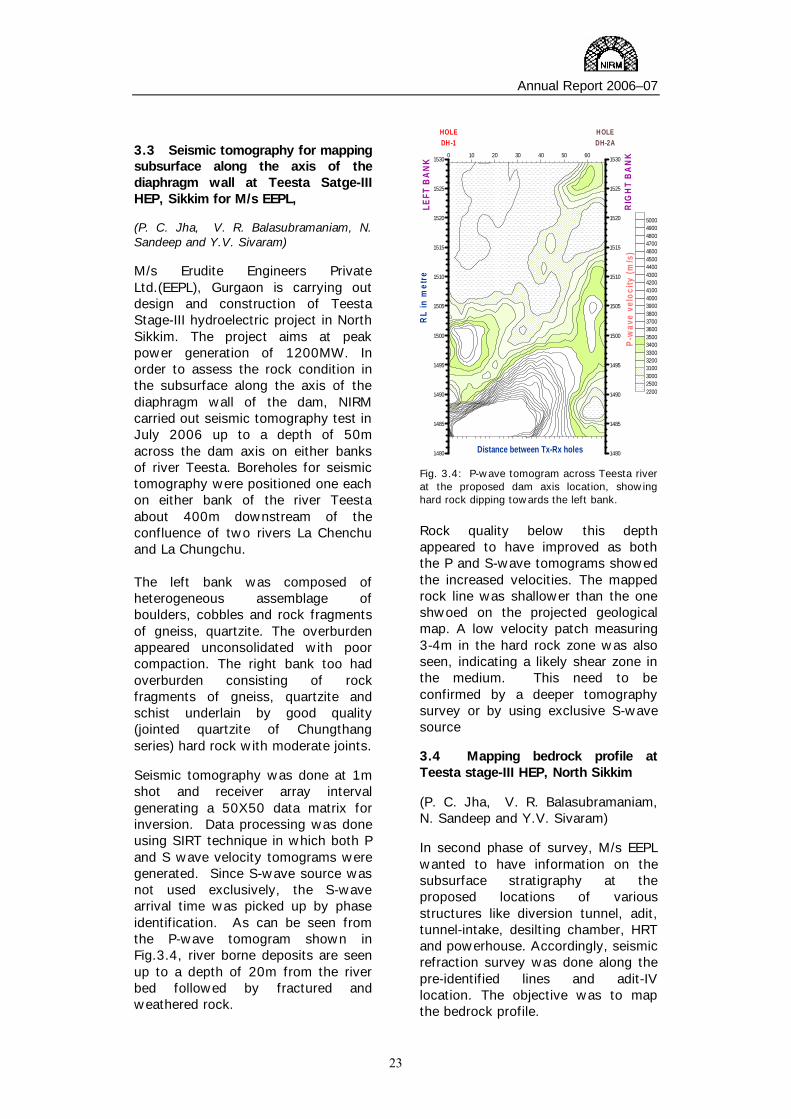
3.3 Seismic tomography for mapping subsurface along the axis of the diaphragm wall at Teesta Satge-III HEP, Sikkim for M/s EEPL, (P. C. Jha, V. R. Balasubramaniam, N. Sandeep and Y.V. Sivaram) M/s Erudite Engineers Private Ltd.(EEPL), Gurgaon is carrying out design and construction of Teesta Stage-III hydroelectric project in North Sikkim. The project aims at peak power generation of 1200MW. In order to assess the rock condition in the subsurface along the axis of the diaphragm wall of the dam, NIRM carried out seismic tomography test in July 2006 up to a depth of 50m across the dam axis on either banks of river Teesta. Boreholes for seismic tomography were positioned one each on either bank of the river Teesta about 400m downstream of the confluence of two rivers La Chenchu and La Chungchu. The left bank was composed of heterogeneous assemblage of boulders, cobbles and rock fragments of gneiss, quartzite. The overburden appeared unconsolidated with poor compaction. The right bank too had overburden consisting of rock fragments of gneiss, quartzite and schist underlain by good quality (jointed quartzite of Chungthang series) hard rock with moderate joints. Seismic tomography was done at 1m shot and receiver array interval generating a 50X50 data matrix for inversion. Data processing was done using SIRT technique in which both P and S wave velocity tomograms were generated. Since S-wave source was not used exclusively, the S-wave arrival time was picked up by phase identification. As can be seen from the P-wave tomogram shown in Fig.3.4, river borne deposits are seen up to a depth of 20m from the river bed followed by fractured and weathered rock.
0 10 20 30 40 50 60
1480
1485
1490
1495
1500
1505
1510
1515
1520
1525
1530
1480
1485
1490
1495
1500
1505
1510
1515
1520
1525
1530
RL
in m
etre
Distance between Tx-Rx holes
P-w
ave
velo
city
(m/s
)
HOLEDH-1
HOLEDH-2A
LEFT
BA
NK
RIG
HT
BA
NK
22002500300031003200330034003500360037003800390040004100420043004400450046004700480049005000
Fig. 3.4: P-wave tomogram across Teesta river at the proposed dam axis location, showing hard rock dipping towards the left bank. Rock quality below this depth appeared to have improved as both the P and S-wave tomograms showed the increased velocities. The mapped rock line was shallower than the one shwoed on the projected geological map. A low velocity patch measuring 3-4m in the hard rock zone was also seen, indicating a likely shear zone in the medium. This need to be confirmed by a deeper tomography survey or by using exclusive S-wave source 3.4 Mapping bedrock profile at Teesta stage-III HEP, North Sikkim (P. C. Jha, V. R. Balasubramaniam, N. Sandeep and Y.V. Sivaram) In second phase of survey, M/s EEPL wanted to have information on the subsurface stratigraphy at the proposed locations of various structures like diversion tunnel, adit, tunnel-intake, desilting chamber, HRT and powerhouse. Accordingly, seismic refraction survey was done along the pre-identified lines and adit-IV location. The objective was to map the bedrock profile.

Annual Report 2006–07
24
The data was collected using a 24-channel seismograph at 5m interval of geophone array using both hammer and explosives source. The survey results showed that the site was characterised by thick overburden comprising huge boulders, rock fragment with highly weathered rock mass condition.
Fig.3.5: Typical seismic section along the transverse line showing hard rock dipping towards the river at approximately 300. In the seismic section (fig.3.5), hard rock was generally found beyond 30m depth from the surface. Hard rock profile was quite undulating along the river, but the transverse profile showed that the hard rock was dipping towards the river on either banks. No anomalous feature was found in the survey region.
3.5 Mapping bedrock profile at Teesta stage-VI HEP of M/s LANCO Energy Pvt. Ltd. In South Sikkim (P. C. Jha, V. R. Balasubramaniam, N. Sandeep and Y.V. Sivaram) Teesta Stage-VI HEP at Sirwani in the southern part of Sikkim is being implemented by M/s Lanco Energy Pvt. Ltd (LEPL). Peak power generation out of this project is
expected to be 500MW. To finalise design of subsurface constructions like in-take tunnel and desilting chamber, M/s LEPL wanted to have the bedrock profile around the proposed sites. Accordingly, seismic refraction survey was done on the right bank hill of the river Teesta using a 24-channel geophone array at 5m interval with explosives source for mapping up to a depth of 60m. Seismic refraction profiles were gathered for a total length of 1820m along both longitudinal and transverse lines at various subsurface structures locations.
Fig. 3.6: Typical seismic section along line XL-3 showing hard rock dipping towards the river at approximately 320.
The survey results (fig.3.6) revealed that up to 20-25m depth, weathered to semi-weathered strata conditions dominate the subsurface strata. Rock mass conditions appeared to have improved beyond 50m depth. Hard rock was expected to be continuous below RL 450m. It was suggested that the availability of suitable rock conditions around the central survey region, where jointed rock was expected, should be ascertained by drilling before design of subsurface construction.

Annual Report 2006–07
25
Rock Fracture Mechanics and Material Testing (G. M. Nagaraja Rao,. S. Jayanthu, S. Udayakumar, S Satyanarayana & M Victor)
NIRM is equipped with modern laboratory facilities to carry out basic research on rock fracture mechanics. The laboratory is engaged in frontier areas of research such as thermo-mechanical behaviour of rocks, and has developed expertise in the application of acoustic emission and ultrasonic imaging techniques. For granite and other dimensional stones, facilities have also been developed for carrying out abrasion test, impact test, reflectivity (Gloss), hardness and petrography. The major testing facilities related to these studies include :
i) Equipment for preparation of rock samples as per international standards ii) Hoek and SBEL high temperature and pressure triaxial cell iii) 150 ton MTS stiff compression testing machine iv) Acoustic emission monitoring system v) Equipment for determining joint properties
The Materials Testing Laboratory is accredited by DGMS, Dhanbad, to carry out tests on mining machinery parts, such as :
i) Wire rope testing ii) Proof load testing iii) Hydraulic prop testing iv) Non-destructive testing both in the field and laboratory
4.1 Laboratory Geotechnical Investigations of Katra-Qazigund Rail link of Northern Railways in J&K.
(G.M.Nagaraja Rao, S.Jayanthu & S.Udayakumar) RITES is carrying out Geotechnical investigation on Katra-Qazigund rail line project for construction of railway line, tunnels and bridges. In this regard laboratory investigations were carried out on bore hole-drilled samples to determine the following properties.
• Specific gravity • Water absorption • P-wave velocity • Slake durability • Uniaxial compressive strength • Young’s modulus • Poisson’s ratio • Tensile strength • Point load strength index and • Shear strength Thirty-six rock types were tested between the chainage of 50 to 147
4

Annual Report 2006–07
26
km and the samples were with in a depth of 50m from the surface. Fractures were observed in almost all the samples. Samples were prepared and tested as per the ISRM suggested methods. The salient findings of the investigation are:
1. There was not much variation in
the specific gravity (varied between 2.45 to 2.80) for all rock type except for basic rock for which the value is 3.17.
2. Water absorption more than 1 % was observed for biotite granite claystone, carbinaceous phillite, felspathic quartzite and phyllite quartzite, and for the remaining 32 rock types it is less than 1%.
3. Most of the rock type are having P-wave velocity between 2.41 to 5.05 except for basic rock and dolomite which are having velocities 5.33 and 6 km/sec. respectively.
4. Slake durability was determined only for basic rock, dolomite, felspathic quartzite, grain trip and quartzite. Among these dolomite showed lower slake durability values of about 80% but the remaining showed a slake durability around 99%.
5. Based on uniaxial compressive strength, rocks can be broadly classified into three groups as given below.
Range MPa Rock type
< 100
Schist ,Gneissose schist ,Phylite , Phillitic Gneise ,Granitic mica schist , Felspathic Quartzite, Shale ,Basic Rock , Granite gneiss, Clay stone ,Quartzite
100 to 150
Gneissic granite , Gneiss, Dolomite, Biotite granite, Siltstone, Sand stone
>150 Grain trip ,Limestone, Granite
6. Young’s Modulus for most of the rock types varied between 20 to 50 GPa. But for basic rock (53GPa), Dolomite (71GPa), Lime stone (55GPa) and quartzite (51GPa) was
more than 50GPa. Shale showed the lowest Young’s modulus of 17.5GPa.
7. Poisson’s ratio of most of the rock type varied between 0.17 to 0.23. But for the shale and gneissose schist it was 0.12 and 0.26 respectively.
8. Only a few rock types were tested for tensile strength and the average values are :
Basic rock : 25.38 MPa Felspathic quartzite : 6.81 MPa Phylite :10.16 MPa Quartz : 8.41 MPa Schistose quartzite : 4.85 MPa
9. Point load strength index varied from 2 to 4 MPa for most of the rock types, but for basic-volcanic (6.69 MPa) , dolomite (4.70 MPa), sandstone (5.46Mpa) and silt stone (4.21 MPa) was more than 4 MPa. Quartzitic phyllite showed the lowest value of 0.85 MPa.
10. Shear strength was estimated from triaxial compression test for few rock types and the values are as follows:
Dolomite : 26 MPa Gneiss : 26 MPa Granite gneiss : 16MPa Phylite : 11 MPa Sandstone : 41 MPa and Schist : 20 MPa
4.2 Physico-Mechanical Properties of Rocks - A Data Bank
(S.Jayanthu, G.M.Nagaraja Rao & S.Udayakumar)
A effort was made to compile the data on rock properties from various projects (29 projects) carried out by the laboratory since 1993. The data bank comprise of the physico-mechanical properties of rocks for different mines, tunnels, caverns etc. While compiling the data, the original table numbers, nomenclature, other details etc. were retained for

Annual Report 2006–07
27
further verification/ identification of the data. The physical properties included density, water absorption, porosity, slake durability index, P-wave velocity etc. The mechanical properties include uniaxial compressive strength, Young's modulus, Poisson's ratio, tensile strength and triaxial compressive strength etc. From the Triaxial compression data, cohesion, friction angle & 'm' (constant in Hoek-Brown failure criteria) are also calculated. All these properties were not determined for all the projects as the tests were conducted as per the requirements of the clients. The procedure followed for preparation of rock samples, methodology followed for testing for determining the rock properties are also presented for better understanding of the source of the data bank, along with its usefulness and limitations The uniformity of presentation in the data bank could not be maintained due to the varied nature of the projects. However, this report can be used as a reference material.
4.1.3 Testing of Rocks and Dimension Stones
(G.M.Nagaraja Rao, S.Jayanthu & S. Uday Kumar) Rock samples were tested in the laboratory as per ISRM/ASTM suggested method/standard for various properties: physical (density, water absorption, specific gravity, porosity, P & S wave velocity); mechanical (uniaxial Compression test & Elastic constants, Tensile test (Brazillian test), triaxial compression test; and joint properties (joint wall compressive strength; Basic and Residual friction angle, Normal and Shear stiffness). These properties were tested for the samples provided by more than eight agencies. 4.2 MATERIALS TESTING
(G. M. Nagaraja Rao, S. Jayanthu, S. Satyanarayana & M Victor) Wire rope testing and in-situ non-destructive testing were carried out for various industries which include Hutti Gold Mines Limited, Ferro Alloys Corporation Limited, Singareni Collieries Company Limited, Tamil Nadu Electricity Board, Hindusthan Zinc Limited, Manganese Ore India Limited., Faiveley Transport India Ltd., BEML, K.G.F. & Mysore. In-situ non destructive testing is being carried out for almost industries of India.

Annual Report 2006–07
28
Numerical Modelling and Stability Analysis
(Sripad, G. D. Raju, K. Sudhakar, P. S. Varma and V P Mishra)
Numerical modelling is one of the major tools for design of excavations in rock. The Institute has experienced civil and mining engineers with expertise in this area, providing solutions to problems in various types of excavations in rock. We have the latest numerical modeling software based on discrete and continuum element methods. We undertake :
i) The stress analysis and support design for tunnels, large underground excavations, storage caverns
ii) Rock-liner interaction analysis for pressure shafts iii) Coupled thermo-hydro-mechanical analysis of the rock mass iv) Dynamic analysis including seismic and liquefaction behavior Stability
analysis of earth dams and slopes 5.1 Instrumentation, monitoring and Data Analysis of Underground Powerhouse Complex, Desilting Chambers of Tala Project, Bhutan
(Sripad, G. D. Raju, K. Sudhakar, P. S. Varma & R. N. Gupta) Tala Hydroelectric Project is a joint venture project between the Government of India and Royal Government of Bhutan for the construction of 1020 MW run of the river scheme. NIRM carried out instrumentation work at all the underground excavations in this project since the year 2000. 5.1.1 Instrumentation during excavation of the crown portion
Four sections each along the length of Machine Hall and Transformer Hall Caverns were selected for instrumentation. It was decided to
install Multi Point Bore Hole Extensometers (MPBX) of magnetic type in the center of the crown and left and right sides of the crown for measuring the deformations in the surrounding rock mass. At the same sections, the load on the rock bolts was measured using vibrating wire anchor load cells. The load cells were installed on the ribs at EL 533 level at six locations in Machine Hall and six locations in Transformer Hall. The measurement of pore water pressure was done by piezometers. The convergence of the ribs was monitored using reflective paper targets using total station. 5.1.2 Instrumentation during benching
Based on the 3D numerical modeling studies carried out by NIRM, instrumentation was carried out at EL
5

Annual Report 2006–07
29
525, 520, 515 and EL 506 at four locations in Machine Hall. At Transformer Hall, instrumentation was carried out at EL 525 and EL 520 at four locations. The behaviour of the cavern was studied using various types of instruments installed during each excavation stage. The convergence of the side wall of the cavern was measured using reflective target and total station. The load on the rock bolts was measured using anchor load cells. Instrumented bolts were used to measure the stress levels at various depths in to the rock mass. 5.1.3 Instrumentation in the invert
After, the reported upheaval at the invert of the machine hall cavern, an extensive instrumentation plan was prepared for turbine pits to monitor the time dependent behaviour of the invert and to monitor the efficacy of the supports installed on the turbine pit floor. Accordingly, 20m long MPBX of magnetic type were installed at the intersection of centre line of the cavity and TRT manifolds at Pits and were further supplemented by prism target observations using total station. The monitoring continued till the instruments showed stabilization trends. The instrumentation layout at Machine Hall Cavern and Desilting Chamber is shown in Figure 5.1.
Figure 5.1. Section of Machine Hall Cavern and Desilting Chamber showing the location of the instruments
The stability of the machine hall cavern was assessed based on the convergence observations of the side walls, the load on the rock bolts and the stress distribution along the length of the instrumented bolts and the floor heave observations. It may be noted that in most of the locations, the load on the rock bolt is either decreased or increased minimally during the last one year. The maximum load measured was 40.96 tons at RD 150 d/s at EL 520 and shows a stabilising trend. The analysis of instrumented bolt data also indicates that there are no appreciable changes in the stress levels on the rock bolts. At RD 65 downstream, there was a tensile stress of 394.50 tons during Dec -05 which later reduced to 338.70 tons and since then is showing a stabilising trend. During the reporting period, the convergence observations were continued at EL 525 and EL 520 at Machine Hall Cavern. The average convergence rate is in the range of 0.017 to 0.027mm/day, which have reduced from the earlier rates (0.6 to 0.11mm/day). The convergence observations at EL 525 at Machine Hall Cavern are shown in Figure 5.2.
135.30
353.35
327.28
265.71
0
50
100
150
200
250
300
350
400
01/0
9/20
02
04/0
1/20
03
09/0
5/20
03
11/0
9/20
03
14/0
1/20
04
18/0
5/20
04
20/0
9/20
04
23/0
1/20
05
28/0
5/20
05
30/0
9/20
05
02/0
2/20
06
07/0
6/20
06
10/1
0/20
06
12/0
2/20
07
17/0
6/20
07
Date
Con
verg
ence
, mm
RD 15 RD 65
RD 110 RD 150
Excavation of Main Benches
EL 525 - EL 499.5
Excavation of Sump , Trench &
Bus Ducts
Post Excavation Period
Figure 5.2. Convergence of side walls of Machine Hall Cavern at EL 525 Observations of floor heave for more than 500 days indicate that the floor heave, observed during the initial period, was completely arrested after completion of RCC and there was no
Annual Report 2006–07
30
further increase in the floor heave at any of the locations at turbine pits. The behaviour of the cavern is tending towards stability as expected during the period of excavation and post excavation period. The behaviour of the cavern is currently under the process of stabilisation and undergoing time dependent deformations. Instruments observations at Transformer Hall, Bus Ducts and other locations also indicated a stabilising trend. At desilting Chambers, the load cells and piezometers were terminated at remote locations for monitoring during the operation stages. The pore water pressures in the surrounding rock mass shows a trend as expected. 5.2 Deformation Monitoring of Underground Powerhouse Cavern of Sardar Sarovar Project, Gujarat
(Sripad, G. D. Raju, P. S. Varma & V.P.Mishra) Underground powerhouse complex at the Sardar Sarovar Project consists of powerhouse of 23m wide, 57m high and 210 m long. There are six pressure shafts of 9m diameter for intake of water from the reservoir to the powerhouse and six draft tubes of 16m wide double D-shaped for drawing out water to collection pool. On the downstream side, there are three D-shaped bus galleries of 12m wide and 7.5m high connected to bus shafts. There are few interconnecting tunnels and access tunnels, which are close to the powerhouse. The present investigation is continuing since 2000. It includes monitoring of the existing MRMPBX (Magnetic Ring Multi Point Borehole Extensometer) and to install and monitor fresh total station targets. The objective of this investigation is :
• To continue monitoring of wall movement using the existing MRMPBXs
• To install and monitor fresh total station targets for convergence of the cavern
• To install and monitor MRMPBXs to assess the cable anchor performance
• To assess the long term stability of the powerhouse and to compare the results with those of numerical modeling.
Conclusions:
a. The wall movements at different locations during the investigation period showed a stable trend, except at two locations.
b. The precision triangulation also indicated that the wall movement did not increase during this period.
5.3 Analysis of Instrumentation Data of Machine hall and Desilting Complex of NJHEP, SJVNL, Shimla
(Sripad, G. D. Raju, P. S. Varma, & R. N. Gupta) The Nathpa Jhakri Hydroelectric Project of SJVNL consists of underground powerhouse complex of 1500 MW located at Jhakri and one of the largest underground desilting complex of 4 numbers of 525m long with a cross section of 27x17m each separated by 46m rock pillar located at Nathpa. The project was commissioned and impounding of desilting chambers started in November 2003. NIRM carried out stress analysis and instrumentation of powerhouse and desilting complexes and recommended the support design. The SJVNL has requested NIRM to carry out analysis of instrumentation data of powerhouse and desilting complex supplied by SJVNL to ascertain the stability of the caverns during operation. The data of various instruments like peizometers and extensometers installed in PH complex Desilting

Annual Report 2006–07
31
complex, supplied by SJVN was analyzed for deformation and pore pressure in the rock mass around the caverns of powerhouse and desilting complexes. The summary of data analysis is as follows • The rock mass movements have not
increased during operation.
• The pore pressures observed during impounding are as expected.
• The analysis of instrument data during operational stage indicate that the caverns are stable
5.4 Instrumentation of Machine Hall & Transformer Cavern of PUSHEP, TNEB, Chennai
(Sripad, R. Venugopala Rao, G. D. Raju, P. S. Varma, S. Sengupta & R. N. Gupta) The power house complex of Pykara ultimate stage hydroelectric project is nearing completion. The pillar between the machine hall and transformer cavern was monitored to ascertain its stability using magnetic
ring multi point extensometers. It was decided that the monitoring should be continued during operation stage for one year. It was also decided to monitor the convergence of machine hall cavern using total station and build up of pore pressure. The scope of the present instrumentation is :
• Procurement of instruments
• Installation of pore pressure cells and targets
• Monitoring of pore pressure around machine hall and transformer cavern, wall surface movement using total station
• Monitoring of movement of rock mass in the pillar with existing Magnetic Ring MPBX
During the reporting period, there was no movement of the walls and no buildup of pore water pressure at any locations. Final report was submitted during July 2006.

Annual Report 2006–07
32
Rock Excavation and Blasting (G. R. Adhikari, Dr. H. S. Venkatesh, A. I. Theresraj, R. Balachander)
The Institute provides solutions to challenging problems in blasting for various mining and civil engineering projects. We are equipped with the latest micro processor based instruments like seismographs, laser profiler, velocity of detonation measuring systems and digital video camera for blast monitoring. The Scientists have developed various techniques to optimise blast design parameters for surface and underground excavations, and assisted in executing some of the major controlled blasting operations. The Scientists are closely working with the industry providing solutions to practical blasting problems in the following areas :
i) Optimisation of blast design parameters for mining and hydel projects (surface and underground)
ii) Monitoring and control of ground vibration, air overpressure and fly rock iii) Rock mass damage control iv) Development of blasting techniques and instrumentation
6.1 Design for Excavation of Basin at Koldam Hydro Electric Project and Ground Vibration Monitoring, Afcons RN Shetty & Co. Pvt. Ltd. Joint Venture (H.S. Venkatesh, R Balachander, Kavindra Kumar, A I Theresraj, G.R. Adhikari and R N Gupta)
The National Thermal Power Corporation Ltd. (NTPC) is setting up an 800MW (200MW x 4 units) hydel power project on Sutluj river at Koldam in Himachal Pradesh. The project involves surface and underground excavation of rock. As part of this project, the excavation and construction of the desilting basin was awarded to Afcons & R.N Shetty Joint Venture (ARJV). The ARJV approached NIRM to guide them in
excavation by drilling and blasting in a safe manner and to monitor ground vibration produced from the blasts. The dimension of excavation is 150m long, 90m wide and 24m deep in the rock with about 3 lacs cubic meters of rock to be excavated. Accordingly, trial blasts were conducted during which ground vibrations were monitored at different locations and the data generated during the first month was used to derive the site specific predictor equation. Similar predictor equation for air overpressure was also derived. The dominant frequency of ground vibration varied between 5-40Hz. The vibrations monitored on the concrete structures present in the vicinity of blast site showed that the levels were
6

Annual Report 2006–07
33
within the safe limit prescribed by NTPC. A suitable pre-splitting blast was designed to reduce the damage to rock mass when the excavation reached the pit limit. Control measures for vibration and air overpressure was suggested from time to time. Thus the overall blast design was optimized, which increased the production, productivity and safety. 6.2 Blast design for various excavations related to Bhaba Tail Race Diversion on the right bank river Sutluj, HP State (A.I Theresraj, G.R. Adhikari, H.S. Venkatesh, R Balachander and V P Mishra)
The Satluj Jal Vidyut Nigam Ltd. had raised the height of the Nathpa dam by another 5 m (EL 1500 m) in the second phase leading to the possibility of submergence of the existing tail race tunnel. Suitable provisions were made on the right bank of Satluj river at Nathpa to divert the tail water discharge of Bhaba Tail Race Diversion Tunnel. This involved construction of civil works including the excavation of tunnels and an underground water collection chamber, pump house and discharge tunnel. In addition, an additional main access tunnel was proposed at EL 1504m (portal invert) for linking with the existing permanent access tunnel of the Bhaba project. Field visits were made at different stages of the excavation. Structures around the project site both in surface and underground were identified for vibration monitoring. Blast designs for various excavations were reviewed, prepared and suitable suggestions were made for fine tuning. Most of the excavations were completed using jackhammer holes and long period delay detonators. The recorded blast vibrations at surface and underground structures were very low and well within the permissible limits.
6.3 Monitoring of ground vibration and air overpressure due to quarry blasting at Ravagodlu stone quarry of Sri Venkateshwara Hill Crushers, Ramnagar, Bangalore (G.R. Adhikari, R. Balachander, A.I. Theresraj, H.S. Venkatesh and V.P. Mishra)
Sri Venkateshwara Hill Crushers, Ramnagar, Bangalore is operating a stone quarry which is located at Ravagodlu village, Bangalore South to feed their crusher. The stone from the quarry is excavated by drilling and blasting. The quarry owner approached NIRM to conduct a study on ground vibration and air overpressure produced by blasting. Accordingly, NIRM inspected the site and found that the quarry had two developed working faces on the North and the South at about 300m apart. It was a manual quarry which used drilling and blasting for excavation. There were no structures within 500m from the North working face where the Bettahalli Kaval village was located at about 425m from the south face. During field study, monitoring was carried out in and around the quarry in as well as in the villages. In all, 12 blasts were monitored with sufficient number of vibration monitoring instruments deployed at different distances. The recorded vibration levels at the two villages were as low as 0.4mm/s. The air overpressure was recorded far below the permissible level.
Using the monitored vibration data, predictor equations were derived for the estimation of ground vibration and air overpressure. Suitable measures were recommended for control of ground vibration and air overpressure.

Annual Report 2006–07
34
6.4 Monitoring of Ground Vibration, Air Overpressure and Flyrock due to Quarry blasting at three stone quarries in Kolar District. (G.R. Adhikari, H.S. Venkatesh, A.I. Theresraj, R. Balachander, and V.P. Mishra)
A number of stone quarries are being operated at Narasapur Hobli, Vemgal and Tekal Hobli in Kolar district, Karnataka. These quarries mostly use crushers to generate stone chips of designated sizes. As the granite rock was hard, explosives were used by them for primary breaking of stone blocks. There were complaints from the nearby villages with regard to vibration, air overpressure and flyrock. The Jelly Owners welfare Association along with Geologist from the Department on Mines and Geology, Kolar approached NIRM to carry out field studies related to ground vibration, air overpressure and flyrock due to blasting at three quarries and suggest measures for containing them within safe limits. Accordingly studies were carried out at three quarries during which owners were asked to conduct about ten experimental blasts. Jackhammers were used to drill 2m deep blast-holes. The number of holes was varied, charged with ANFO and blasted with instantaneous electric detonators. In order to ascertain the levels of vibration and air overpressure produced by these blasts, 10 microprocessor-controlled seismographs were deployed in and around the quarries up to the nearby villages. The distances from the blast locations and the instrument locations were measured using a laser locater. The extent of the flying fragments at the monitoring stations was physically observed during the blasts. The data so generated were analysed to derive site-specific predictor equations for vibration and air overpressure. Based on these equations, the danger zones were delimited for each quarry.
It was found that all the experimental blasts were well within the permissible limits of vibration and air overpressure up to at a distance of 200m. However, the limit of 200m as per the KMMC rules of 1994 was inadequate from flyrock point of view. 6.5 Blast vibration studies at Ganvi HEP Stage II (10MW) and at Kashang HEP Stage I (66 MW), Himachal Pradesh Jal Vidyut Vikas Nigam Limited, Himachal Pradesh (G.R. Adhikari, H.S. Venkatesh, A.I. Theresraj and R. Balachander)
The Himachal Pradesh Jal Vidyut Vikas Nigam Limited (HPJVVNL) is constructing two mini hydel projects viz., Ganvi Stage-II (10MW) in Shimla district and Kashang Stage-I (66 MW) in Kinnaur district of Himachal Pradesh. The project components at Ganvi site comprised main access tunnel, powerhouse, surge shaft and headrace tunnel while the only component at Kashang site was the main access tunnel. While the project authorities were executing these excavations by drilling and blasting method, there were complaints of excess ground vibration and air overpressure. In addition, a landslide near Pangi village was also attributed to blasting at main access tunnel of the Kashang project. At the request of HPJVVNL, NIRM carried out field investigations at both the project sites. At Ganvi project site, blast vibration and air overpressure were recorded at different villages. At Kashang project site, there were no villages within 1 km from the excavation site. Ground vibrations and air overpressure were monitored within a radius of 700m and found to be very low. In order to ascertain the role of blasting induced vibration triggering the landslide which was at about 600m from blast site, two units of seismographs were placed on either side of the Pangi landslide. The recorded vibration levels were found to be very low.

Annual Report 2006–07
35
Therefore it was concluded that the landslide was not triggered by blasting. At both the projects, the recorded ground vibration and air overpressure levels were found much lower than the permissible levels. At such low levels, there was no possibility of any adverse impact of blasting on the nearby structures in the villages. Therefore it was recommended to continue the existing drilling and blasting parameters. 6.6 Monitoring of ground vibration due to quarry blasting at Visaka Cement Quarry, Tandur, AP (G.R. Adhikari, H.S. Venkatesh, A.I. Theresraj and R. Balachander) As per the objectives of the study, ground vibration has to be monitored twice a year for a period of two years. For each visit, four blasts should be monitored. Accordingly, during this year, two visits were made and the monitoring results were submitted. Project will continue for another year. 6.7 To study the effects of ground vibration due to blasting in the nearby villages at Loharinag-Pala Hydro Power Project, Uttaranchal, NTPC (A. I. Theresraj, R. Balachander, G.R. Adhikari and H.S. Venkatesh) Loharinag – Pala Hydro Power Project (4 x 150 MW) of the National Thermal Power Corporation Limited (NTPC) is located on the right bank of river Bhagirathi in Uttarkashi district of Uttranchal. The initial development of
this project started with the construction of approach roads to three adits for excavation of head race tunnel. When construction of approach roads was being carried out by drilling and blasting, complaints of houses developing cracks due to impact of blasting were received from the surrounding villages. At the request of NTPC, NIRM monitored ground vibration and air overpressure in the villages closer to the blast sites to assess whether these parameters were within the permissible levels. In total, ten blasts were monitored, five each in two approach roads. In all, 41 sets of ground vibration data were used to derive a site-specific predictor equation by regression analysis. Similarly, 34 sets of air overpressure data were used to derive an empirical equation for estimating the air overpressure level. A draft report was submitted suggesting remedial measures to contain ground vibration and air overpressures. 6.8 Study on ground vibration, air overpressure, flyrock and optimum charge & blasting pattern for controlled blasting, Sankari Works, ICL, Salem (G.R. Adhikari, H.S. Venkatesh, A.I. Theresraj and R. Balachander) Preliminary site visit was made to understand the problems and to chalk out the plan for future investigations. It is proposed to carry out field investigations from May 2007 onwards.

Annual Report 2006–07
36
Dimension Stone Technology
(A. Rajan Babu)
The Institute is providing technical services to dimensional stone industry for quarrying, optimum recovery and economic exploitation of granite and other dimensional stones. Our areas of work include :
i) Geological and geotechnical studies to characterize the deposit for scientific exploitation.
ii) Rock testing to determine the various properties required for exploitation and marketability of stones.
iii) Quarry planning for economic exploitation and selection of equipment. iv) Design of controlled blasting/splitting techniques to reduce the damage
to blocks and to optimize the recovery. v) Planning and design for waste disposal and environment protection. vi) Techno-economic evaluation of the project and preparation of feasibility
report. vii) Conduct training courses and seminars for operating personnel for
exchange of information. 7.1. Setting up of a Test House at Jaipur
(A. Rajan Babu, S.Udayakumar, P.K. Behera & R.N. Gupta) The project was completed and final report incorporating various details was submitted. The scope of work included 1) Layout of the building, 2) Type of testing facilities to be catered, 3) Equipment for conducting various tests, 4) Specification of the equipments with possible suppliers, 5) Tests standards to be observed and 6) Staff requirements. Recently the test house was commissioned successfully and is ready for taking up testing jobs.
7.2. Training Programme on Scientific Quarrying & Production of Dimensional Stone Granites at P. R.P Granites, Madurai, Tamilnadu (A. Rajan Babu, G.R. Adhikari & V.P. Mishra)
The Training programme was conducted on 20-21 June 2006 in the site office was inaugurated by Shri. P. Palanichamy, Founder & Managing partner of P.R.P Granites. In all, 30 participants attended the training programme from various quarries of P.R.P Granites. They had taken very keen interest in the classroom lectures. The training focused mainly on the production process of granite
7

Annual Report 2006–07
37
blocks and the intricacies in terms of scientific knowledge needed for achieving optimum recovery of saleable blocks.
TOPICS DELIBERATED 1. Glossary of Scientific and Quarry Terms 2. Granite Manufacturing Process 2A. Dimensional Stone Granite Quarrying (Summary) 3 Stone Quarrying for Aggregates 4 Status of Granite Quarrying in India 5 Exploration of Dimensional Stone Deposits. 6 Blasting in Dimensional Stone Quarries 7 Development and Planning of Granite Quarries 8 Introduction to New Development in Quarrying
Technology 9 Case Studies
Discussions were mainly focused on planning and design of benches for continuous production and topics related to method of mining. Special interest was shown to implement the block spitting techniques. It was pointed out that most of the quarries were experiencing severe damage to the blocks due to want of a controlled blasting technique for block spitting as well as overburden removal. The participants suggested that the training programmes shall be conducted on specific topics at regular intervals. 7.3. Technical guidance and advice for blasting operations for the excavation related to the underground LPG storage cavern, Visag
(A. Rajan Babu, G.R. Adhikari & R.N. Gupta) The project was completed successfully fulfilling the scope of work in total. The first blast for the excavation of the shafts was taken on 15th June, 2004 in operation shaft and on 27th July, 2004 in access shaft. The final blast in the main cavern was concluded on 20th November 2006. The draft report incorporating all the method statements, designs and drawings is ready.
Designs and Method Statements Submitted
Sl. No
Title and List of Method Statements Submitted
1 Blast design for the excavation of Storage Cavern using Powerbulk Drive (Rev)
2 Blast design for 10 m wide Upper Connection
3 Blast design for Access Ramp
4 Blast design for the excavation of Access Ramp using Powerbulk Drive
5 Blast design for 10 m wide Upper Connection - heading - wedge cut alternative
6 Blast design for excavation of 4.5m high bench in USC & UC
7 Blast design for water curtain gallery 4.0 m x 3.5 m (wedge cut alternative)
8 Alternative blast design for excavation of 4.5m bench in USC & UC
9 Blast design for COUC & COLC
10 Blast design for the excavation of upper connection using Powerbulk Drive
11 Blast design for the excavation of Intermediate Connection using Powerbulk Drive (Rev)
12 Blast design for the excavation of Lower Connection using Powerbulk Drive (Rev)
13 Blast design for the excavation of Lower Shaft Connection using Powerbulk Drive
14 Blast design for the excavation of UC 10X4.5m bench using Powerbulk Drive
Dimensions of the excavation :
Name of excavation
Height X width, m
Shape Cross
sectional area, m2
Volume m3
Access shaft 6.5 m dia, Depth=170m
circular 34.2 5816.13
Operating shaft
4 m dia, Depth=182m
circular 13.2 2344.39
Water curtain gallery
4 x 4 Length=210m ‘D’ 14.28 2940
Water curtain/
Access shaft connection
4 x 4 Length=7.5m ‘D’ 14.28 105
Water curtain/Opera
-tion shaft connection
4 x 4 Length=14.5m ‘D’ 14.28 203
Upper shaft connection
8 x 5.5 Length=12m ‘U’ 44 528
Lower shaft connection
5 x 4.5 Length=50m ‘U’ 22.3 1115
Access Ramp
8 x 7 Length=114m ‘U’ 57 6498
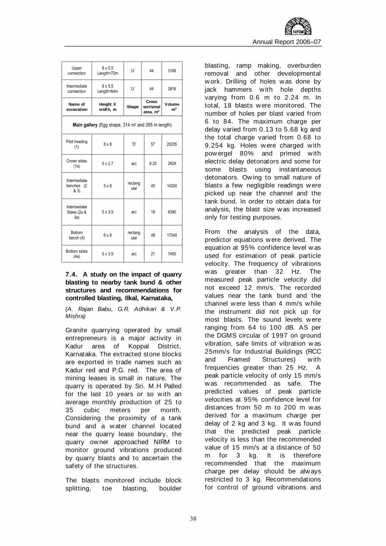
Annual Report 2006–07
38
Upper connection
8 x 5.5 Length=72m ‘U’ 44 3168
Intermediate connection
8 x 5.5 Length=64m ‘U’ 44 2816
Name of excavation
Height X width, m
Shape Cross
sectional area, m2
Volume m3
Main gallery (Egg shape, 314 m2 and 355 m length)
Pilot heading (1) 8 x 8 ‘D’ 57 20235
Crown sides (1a) 5 x 2.7 arc 8.25 2929
Intermediate benches (2
& 3) 5 x 8 rectang
ular 40 14200
Intermediate Sides (2a &
3a) 5 x 3.9 arc 18 6390
Bottom bench (4) 6 x 8 rectang
ular 48 17040
Bottom sides (4a) 5 x 3.9 arc 21 7455
7.4. A study on the impact of quarry blasting to nearby tank bund & other structures and recommendations for controlled blasting, Ilkal, Karnataka,
(A. Rajan Babu, G.R. Adhikari & V.P. Mishra)
Granite quarrying operated by small entrepreneurs is a major activity in Kadur area of Koppal District, Karnataka. The extracted stone blocks are exported in trade names such as Kadur red and P.G. red. The area of mining leases is small in nature. The quarry is operated by Sri. M.H Palled for the last 10 years or so with an average monthly production of 25 to 35 cubic meters per month. Considering the proximity of a tank bund and a water channel located near the quarry lease boundary, the quarry owner approached NIRM to monitor ground vibrations produced by quarry blasts and to ascertain the safety of the structures. The blasts monitored include block splitting, toe blasting, boulder
blasting, ramp making, overburden removal and other developmental work. Drilling of holes was done by jack hammers with hole depths varying from 0.6 m to 2.24 m. In total, 18 blasts were monitored. The number of holes per blast varied from 6 to 84. The maximum charge per delay varied from 0.13 to 5.68 kg and the total charge varied from 0.68 to 9.254 kg. Holes were charged with powergel 80% and primed with electric delay detonators and some for some blasts using instantaneous detonators. Owing to small nature of blasts a few negligible readings were picked up near the channel and the tank bund. In order to obtain data for analysis, the blast size was increased only for testing purposes. From the analysis of the data, predictor equations were derived. The equation at 95% confidence level was used for estimation of peak particle velocity. The frequency of vibrations was greater than 32 Hz. The measured peak particle velocity did not exceed 12 mm/s. The recorded values near the tank bund and the channel were less than 4 mm/s while the instrument did not pick up for most blasts. The sound levels were ranging from 64 to 100 dB. AS per the DGMS circular of 1997 on ground vibration, safe limits of vibration was 25mm/s for Industrial Buildings (RCC and Framed Structures) with frequencies greater than 25 Hz. A peak particle velocity of only 15 mm/s was recommended as safe. The predicted values of peak particle velocities at 95% confidence level for distances from 50 m to 200 m was derived for a maximum charge per delay of 2 kg and 3 kg. It was found that the predicted peak particle velocity is less than the recommended value of 15 mm/s at a distance of 50 m for 3 kg. It is therefore recommended that the maximum charge per delay should be always restricted to 3 kg. Recommendations for control of ground vibrations and

Annual Report 2006–07
39
air overpressure within the permissible limits are also suggested. 7.5. Assessment of the quarry site for safe blasting at Survey No. 201, Aroor Village, Chickaballapur Taluk, Karnataka. (A. Rajan Babu & V.P. Mishra) The District Collector, Kolar District, Karnataka has sought an expert advice from NIRM for storage and usage of explosives for blasting at a stone quarry bearing Survey No. 201, Aroor Village, Chickaballapur Taluk, Karnataka. The technical advice was requested for granting a “No Objecton Certificate” to M/s. K. N. R. Construction Ltd., No. 1034/4, 9th B Cross, Judicial Layout Yalanka, Bangalore, who will be the executing agency. The Controller of Explosives is the authority to grant permission for storing and usage of explosives and therefore the scope was
a) To make a visit to the proposed stone quarry site and record the critical structures etc near the quarry and
b) To suggest measures for safe blasting.
The quarry site is located about 13 km from Chikaballapur town towards Hyderabad. The Aroor village is located at a distance of about 1550 m towards NW and Tumkulapalli village is located about 1800 m towards NE from the quarry site. Within a radius of about 750 m, no other critical structures are observed. The crusher plant and office buildings belonging to the owner are located about 600 m from the quarry site. Precautions and guidelines for safe blasting in terms of vibrations, air overpressure and flyrock were discussed and suggestions made for their effective control. Generalized predictor equation was used for predicting the peak particle velocity at the village and was found to be negligible. A lay-out of controlled
blast design was provided. Measures for safe blasting and code of good practice were also provided. In a nutshell, there is no likelihood of damage to the structures near the quarry from the proposed blasting operations provided that the suggested guidelines are strictly implemented. 7.6. Technical guidance and advice related to the Dimensional Stone Quarrying operations for KIOCL, Bangalore. (A. Rajan Babu, G.R. Adhikari & V.P. Mishra) Considering the huge potential of granite reserves in the state of Karnataka, the KIOCL have taken initiative to invest and operate granite quarries having potential for commercial exploitation. For this purpose, the KIOCL, Management has proposed NIRM to be their consultants to provide Technical guidance and advice related to all aspects of Dimensional Stone Quarrying operations. An MOU is signed between NIRM and KIOCL. The main scope of work is: a) To assist in survey and identification of granite deposits having potential for commercial exploitation and b) To conduct tests on rock samples to establish its quality and assess the market potential. 7.7. Imparting training to the officers of Commissionerate of Geology & Mining, Gujarat, on Exploration, Quarrying techniques & Testing of dimensional stones at NIRM, K.G.F. (A. Rajan Babu & V.P. Mishra) Considering the huge potential reserves of granites, marbles, sandstones, slates, limestones etc, in the state of Gujarat, the Commissionerate of Geology and Mining (CG&M), Gujarat had taken an initiative to promote the dimensional stone industry through bringing in awareness on exploration, quarrying

Annual Report 2006–07
40
technology and testing of stones for quality certification. For this purpose, the CG&M has proposed to get their officers trained by NIRM in the above said areas. Accordingly, the CG&M, has requested NIRM to impart training to ten officers of their department. The main objective is to provide training on various aspects of exploration for dimensional stones, geological and geotechnical
parameters, planning and design of quarries, method of quarrying etc; Dimensional stone testing, analysis of data, interpretation and drawing conclusions at NIRM. The list comprising names of ten participants were received and the training programme is scheduled during 16th to 30th April 2007, which will cover class room lectures, laboratory testing and field visits.
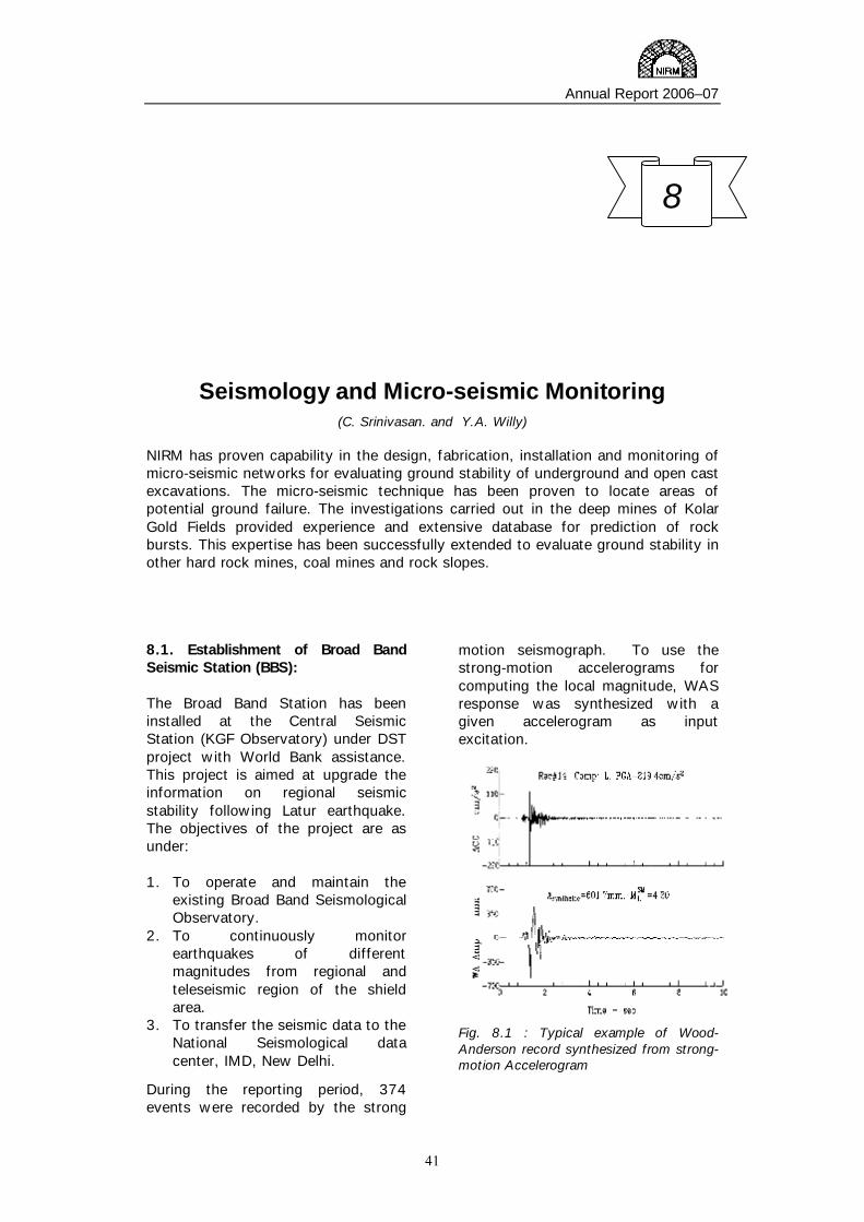
Annual Report 2006–07
41
Seismology and Micro-seismic Monitoring (C. Srinivasan. and Y.A. Willy)
NIRM has proven capability in the design, fabrication, installation and monitoring of micro-seismic networks for evaluating ground stability of underground and open cast excavations. The micro-seismic technique has been proven to locate areas of potential ground failure. The investigations carried out in the deep mines of Kolar Gold Fields provided experience and extensive database for prediction of rock bursts. This expertise has been successfully extended to evaluate ground stability in other hard rock mines, coal mines and rock slopes.
8.1. Establishment of Broad Band Seismic Station (BBS): The Broad Band Station has been installed at the Central Seismic Station (KGF Observatory) under DST project with World Bank assistance. This project is aimed at upgrade the information on regional seismic stability following Latur earthquake. The objectives of the project are as under: 1. To operate and maintain the
existing Broad Band Seismological Observatory.
2. To continuously monitor earthquakes of different magnitudes from regional and teleseismic region of the shield area.
3. To transfer the seismic data to the National Seismological data center, IMD, New Delhi.
During the reporting period, 374 events were recorded by the strong
motion seismograph. To use the strong-motion accelerograms for computing the local magnitude, WAS response was synthesized with a given accelerogram as input excitation.
Fig. 8.1 : Typical example of Wood-Anderson record synthesized from strong-motion Accelerogram
8

Annual Report 2006–07
42
Fig. 8.1 shows two typical examples of the computed W-A seismograms along with the corresponding input strong-motion accelerograms. The magnitudes from the strong motion records are estimated using Asyntentic as follows: ML
SM = log Asyntentic - logA0(R)
where log A0(R) is the Richter’s correction factor for recording at distances more than 100 km, and it basically represents the attenuation of seismic waves with distance. The PGA of both horizontal components have been used to obtain the attenuation relationship for the KGF region. The attenuation relation developed is Log (a) = 0.6037 + 0.3591M - 1.2 log (x + exp (-0.5849M)),
Fig.8.2 : Attenuation relationship derived for local region based on series of series of rockbursts recorded over last two years.
Where a is the peak ground acceleration (g), M is the magnitude, and x is the Epi-central distance from the source. Figure-2 shows the attenuation relation for KGF rockbursts. With the establishment of new Broad Band station seismic events are being recorded regularly. A typical earthquake recorded by the new BBS is shown in fig. 8.3.
Fig.8.3 : Typical record of seismic event as recorded by the broadband station. 8.2. Source Parameters of Seismic events in Kolar Gold Fields.
This is an S&T project of the Dept. of Science and Technology. The objectives are as under:
1. To determine source parameters of rockbursts at KGF, such as corner frequency, seismic moment, source radius, stress drop and dislocation of failure.
2. To know the variation of source
parameters with respect to depth, vicinity of mine working, virgin ground and proximity to geological features like faults, dykes etc.,
3. To understand better the source
mechanism of rockbursts, classification of seismic events into different types and to identify the nature of seismic processes.
During the reporting period, more than 100 rockburst signal from different mining regions have been digitized. The data was sampled at equal interval for carrying out FFT. The digitized signal was short listed for FFT of S-phase of rockburst signals. A Fortran program was written to obtain FFT of rockburst signals.

Annual Report 2006–07
43
Environmental Geotechnology (Surendra Roy)
Environmental Geotechnology Section at NIRM caters to the environmental problems in the following areas of excavation industries:
i) Assessment of air quality, water/effluent quality, noise monitoring ii) Meteorological measurements required in air pollution survey.
iii) Solid waste disposal technique for the protection of environment.
iv) Innovative methods for reclamation of mined areas.
v) Design of dumps for the protection of environment. vi) Assessment of environmental geotechnical properties of mining wastes
(dump), soil, rock, filling materials, etc.. vii) Environmental auditing in excavation industries.
viii) Disposal of fly ash in mined out areas. 9.1. Feasibility study for making bricks from mill tailings, KGF, Karnataka.
(Surendra Roy, G. R. Adhikari and R N Gupta)
This project was meant to contain the environmental hazard posed by tons of mill tailings of gold mines dumped in the open at KGF by using them in constructive application areas so as to minimise the scope of their contamination in the air and ground water. In an attempt to utilize these tailings for industrial use, it was proposed to use them for brick making exercise. Since, plasticity index of the tailings was zero, they could not be used directly for making
bricks. Therefore, ordinary Portland cement, black cotton soil and red soil were used as additives. Each of the additives was mixed separately with the tailings in different proportions by weight and a large number of bricks were prepared. Depending on the additives used, bricks were designated as cement-tailings bricks or soil-tailings bricks. The cement-tailings bricks were cured for a period of 3 to 21 days and their corresponding compressive strengths were determined. It was found that bricks with 20% cement and 7 days of curing met the strength criteria but it would be appropriate to use the bricks cured for
9

Annual Report 2006–07
44
14 days. The soil-tailings bricks using 45 to 65% of mill tailing were prepared, sun-dried and fired at different temperatures. On comprehensive testing, it was found that all of them met the required criteria in terms of compressive strength, linear shrinkage and water absorption. The cost-benefit analysis revealed that soil-tailings bricks would be more economical as compared to cement-tailings bricks. 9.2. Assessment of dust and meteorological parameters at NIRM premises (Surendra Roy, G. R. Adhikari and R N Gupta) The mill tailings dumps around the NIRM campus is expected to pose environmental hazard in terms of air pollution in and around Institute. In order to assess the environmental hazard, a monitoring location was chosen with a view to cover the influence of all the dumps even in case of meteorological variations. The sampling was done for one month each in the winter and the spring season. Sampling was done at 8 hours interval for TSP and PM10 twice a week. Meteorological data on wind speed, wind direction, temperature, humidity, solar radiation and rainfall were also collected by the Automatic Weather Monitoring Station installed in the NIRM campus. The major objectives of dust assessment vis-à-vis meteorological parameters were to quantify PM10 and TSP in different seasons; to analyse correlations between PM10 and TSP; to assess the fraction of PM10 within TSP and their seasonal variation; and to study the influence of meteorological parameters on the particulate. Study results showed that the concentrations of PM10 in winter season was found more than in spring season. The correlation coefficient between TSP and PM10 was 0.86 and 0.82 for winter and spring season
respectively for 8-hourly sampling and 0.90 for both the seasons for 24-hours sampling. Given this correlation, values of PM10 can be assessed if TSP is known. The difference of PM10 in the two seasons was mainly due to the difference in the wind direction. The direction of the wind in the winter season was from the tailing dump side, which caused high values of PM10. The study further showed that even though there was significant variation in the wind direction, the average wind speed in the two seasons did not change significantly. Apart from these studies, the dust monitoring is also being carried out in the summer season and further analysis is in progress. 9.3. Noise study on diesel and electrical based coal mining machinery (Surendra Roy, G. R. Adhikari and R N Gupta)
The objective of the study was to assess environmental noise and operator noise dose for the diesel and electric machines like drill machines, draglines, shovels, dumpers and dozers used in opencast coal mines. Some of them are moveable while others are fixed. The environmental noise is the unwanted outdoor sound created by these mining machines and the noise dose is the amount of noise exposure that an employee is exposed for a given amount of time. In order to protect health and safety of operators and their surroundings, the DGMS has prescribed the occupational exposure noise level of 90 dB (A) in an eight hour shift with unprotected ears but this regulation does not cover the environmental noise. The Government of India has another standard applicable for environmental noise for coal mines
which stipulates a noise level of 75 dB (A) during 6:00 – 22:00 Hrs and 70 dB (A) during other timinings.

Annual Report 2006–07
45
In this study, it is proposed to monitor the noise generated by mining machines so as to determine whether the noise criteria laid down in these regulations are properly complied. 9.4. Study on blasting dust management system in an opencast coal mine
(Surendra Roy, G. R. Adhikari and V. P. Mishra)
The objectives of this study are:
• To study the meteorological condition at the mine site
• To assess the ambient air quality at site following blasting
• To study the influence of rock density, type of explosive and blast design parameters on dust emission
• To develop emission factor for the quantification of dust emission due to blasting
• To develop predictive equation for the dust concentration at a particular location
• To find out control measures for the dust generated due to blasting
After observing the blasting plume behaviour, the suitable monitoring stations have been identified for the installation of instruments at Dudhichua Project, Northern Coal Fields Limited and Bharatpur Opencast Project, Mahanadi Coal Fields Limited. The samples from different benches of these mines were collected and analysed for texture, moisture contents and specific gravity. These parameters are expected to impact the blasting plume behaviour. Further study is in progress.

Annual Report 2006–07
46
Technical Services
( C. Srinivasan, A. N. Nagarajan, A. Vijaikumar and S. L. Mary)
Technical Services Division is a liaison group to provide logistic and infrastructure support to various divisions of the Institute by way of project monitoring, project accounting, technology transfer, library and information services, documentation, publications, publicity and public relations. All the projects of the Institute are regularly monitored through periodic reviews and a record is maintained for the division wise earnings and total cash flow of the Institute. The financial accounting in respect of S&T, consultancy and in-house projects is categorically monitored. The quarterly financial statements in respect of S&T projects are sent to the respective sponsoring agencies. Some of the routine activities of the Technical Services Division are providing input to the Peer Review Committee of the Institute regarding the status of various projects, and forwarding monthly/quarterly progress reports of various projects to the respective sponsoring agencies. The Division also provides secretarial assistance to the Peer Review Committee, Governing Body and General Body of the Institute. 10.1. Project Monitoring Cell The Project Monitoring Cell (PMC) supports all NIRM projects – consultancy/sponsored, S&T and in-house projects. Its activities include preparation of plan documents, annual budget, interaction with sponsoring agencies on the subject and expenditure monitoring. PMC’s activities relating to sponsored projects include submission of proposals, ensuring fund flow and evaluation of customer satisfaction levels.
10.2. Liaison services
Technical information on R&D activities, achievements, on-going projects at various stages of development and capabilities of the various departments are collected. Information about the Institute’s activities have been supplied at the request of the client organisations within India and abroad. Feedback information on R&D activities of the Institute have been provided to the Ministry of Mines, Department of Science and Technology, Indian Bureau of Mines, etc.
10

Annual Report 2006–07
47
10.3. Publications
During the year, NIRM Scientists contributed 13 papers in national / international journals/conferences. Fifty two reports on completed/ongoing projects were submitted to the various sponsoring agencies.
10.4. Annual Report of NIRM
Annual Report for the year 2005-2006 covering various research and industry-sponsored activities, was compiled, published and circulated to various user industries, academic / research institutions. Copies were also forwarded to eminent persons in India and abroad. 10.5. Publicity
Advertisements on Institute,s activities and capabilities were released in various mining journals, souvenirs and newsletters for wide publicity. NIRM represented as institutional and individual membership in various professional societies and technical societies like CBIP, ISNT, ISRM, ISRMTT, MGMI and BIS.
10.6. Library and documentation
The NIRM library is vital to the R&D goals of the Institute. It serves as an important reference section for the scientific staff. The library possesses Indian and foreign publications in the field of Rock Mechanics, Mining Engineering, Geology, Engineering Geophysics, Blasting, Mathematical Sciences, Tunnelling, Seismology. Arrangements are made to avail the library facility of the Indian Institute of Science, Bangalore, by our Scientists. In addition, the Institute also provides photocopies of articles, internal reports, project reports, reference books etc. depending upon the requirements.
Annual Report 2006–07
48
Annual Accounts
11
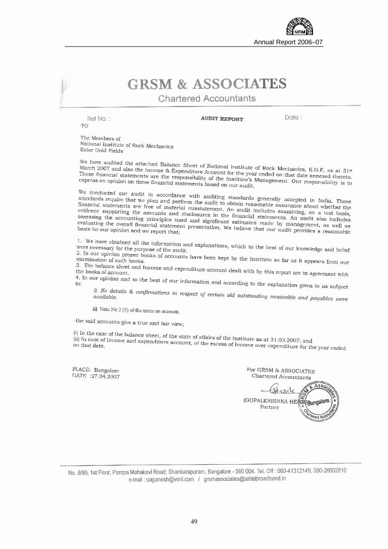
Annual Report 2006–07
49

Sl. No. Particulars Sch
No.Balance as on
01-04-2006
Variation during the year (+)
(-)
Balance as on 31-03-2007
Sl. No. Particulars Sch No Balance as 0n
01-04-2006
Variation during the year
(+) (-)
Balance as on 31-03-2007
Rs. Ps. Rs. Ps. Rs. Ps. Rs. Ps. Rs. Ps. Rs. Ps.1 2 3 4 5 6 7 8 9 10 11 12
1 CAPITAL RESERVE 3244334.00 0.00 3244334.00 1 CURRENT ASSETS
a. Cash in Hand 77099.00 -56262.00 20837.002 OTHER FUNDS b. Cash at Bank 12450895.33 -10097475.30 2353420.03 c. Short Term Deposits 21 54997262.00 19441430.27 74438692.27
a. Deferred Government Grant 30414661.92 -837852.00 29576809.92 d. Stock - Stationery Items 22 86929.49 0.00 95989.49b. Income & Expenditure A/c. 17376211.63 20666201.79 38042413.42 e. Sundry Debtorsc. Institute's Development Fund 60000000.00 0.00 60000000.00 (i) Debtors MTL 23 325459.00 0.00 325459.00
f Accrued Grant-in-Aid 24 14500000.00 -1400000.00 13100000.00
3 CURRENT LIABILITIES2 LOANS AND ADVANCES
I. Creditors - Payroll Deduction a. BGML Ration & Petrol 1 49572.51 0.00 49572.51 I. Interest Bearing Advanceb. K.G.F. Club 2 4413.19 0.00 4413.19 a. Vehicle Advance 25 341318.00 -88732.00 252586.00c .Others 3 7422.50 700.00 8122.50 b. House Building Advance 4900.00 -4900.00 0.00d. PF Subscription 4 0.00 57.00 57.00e. Project Contingency Fund (a) 5 229887.45 -19060.00 210827.45 II. Non Interest bearing Advancef. Project Contingency Fund (b) 64358.00 -64358.00 0.00 a. Festival Advance 26 26700.00 -1350.00 25350.00g. Service Tax- prior period payment 3000020.00 -3000020.00 0.00 b. Material Advance 27 79132.00 82182.00 161314.00
c. Travel/T.T.A 28 397198.00 -9501.00 387697.00II. Other Creditors d. LTC Advance 29 6300.00 3136.00 9436.00a. Provision for Others 5a 85601.40 0.00 85601.40 e.Advance. to Civil Contractors 30 9000.00 0.00 9000.00b. Unclaimed Payment Others 6 5756.65 0.00 5756.65
c. Consultancy Payable to Scientists 7 1297.00 0.00 1297.00 f. Advancefor Capital Material Purchase 31 5238608.40 -2300662.40 2937946.00
d. Undisbursed Payment to Employees 8 40779.00 50024.00 90803.00 g.Medical Advance 32 275462.00 39043.00 314505.00e. Income Tax Contractors 2968.00 -2968.00 0.00 h. Advance to Suppliers 33 74835.00 -1835.00 73000.00f. Advance Received Against Projects 9 108488510.00 -4462065.86 104026444.14g. Caution Deposits for Library 10 6500.00 -3500.00 3000.00 i. Advances - others 34 2000.00 0.00 2000.00h. Earnest Money Deposit 11 175820.00 106176.00 281996.00 j. Imprest A/c 4193.00 -4193.00 0.00i. Security Deposits 12 27837.00 0.00 27837.00 III. Depositsj. Defect Liability 13 57152.61 2863.00 60015.61 a. KPTCL 35 15850.00 0.00 15850.00k. Sundry Creditors for Supplies 14 4357557.00 -3268399.00 1089158.00 b. Deposits - Others 36 8050.00 0.00 8050.00l. Accrued Expenses 15 520505.00 -248786.00 271719.00 c. Telephone / Telex 2000.00 2000.00 0.00m. Honorarium/Incentive 27500.00 -27500.00 0.00 3 OTHER CURRENT ASSETSn. Contribution towards Insurance Prem 16 0 859.00 859.00 a. I T (Refunds) Receivable 37 1069934.00 746189.00 1816123.00o. Other Remittances 17 64081 7273.00 71354.00 b. Expenses on Ongoing Projects 38 56456652.54 1380692.92 57837345.46p. THPA RB0203 Advance 18 25000.08 0.00 25000.08q. Terminal Benefits 0 6847.00 -6847.00 0.00 4 INVESTMENTSr. Advance - Transfer of technology 19 350000.00 0.00 350000.00 Institute Development Fund 39 60000000.00 0.00 60000000.00s. Advance service Tax received 20 0.00 31211.00 31211.00
NATIONAL INSTITUTE OF ROCK MECHANICSCHAMPION REEFS POST, KOLAR GOLD FIELDS
BALANCE SHEET AS AT 31ST MARCH 2007LIABILITIES ASSETS

5 FIXED ASSETSPatents 40 0.00 9000.00 9000.00
Fixed Assets : Gross Block as on 31-03-2006 78623184.00Less : Depreciation 56438369.00 22184815.18 1180186.44 23365001.62Net Block as on 31-03-06 22184815
Gross Block as on 31-03-2007 83241222Less : Depreciation 59876221.00Net Block as on 31-03-07 23365001
TOTAL 228634592.94 8872737.93 237558601.87 TOTAL 228634592.94 8872737.93 237558601.87
0.00
Details of variation during the year 2006-07 (For Deferred Government Grant) Details of variation during the year 2006-07 (For Block of Fixed Assets)
Plan Grant received during the year for capital expenditure 2600000.00 Payments made for purchase of Fixed Assets during the year 4618038.44less: Depreciation for the year 2006-07 reduced from deferred Capital Grants -3437852.00 Less: Depreciation for the year 2006-07 3437852.00Less: Loss on asset written off during the year Less : Net value of assets written off
Variation during the year -837852.00 Variation during the year 1180186.44 As per our Report of even date for G R S M & ASSOCIATES Chartered Accountants
Sd/- Sd/- Sd/- (BIJU MATHEW) (V.P. MISHRA) Sd/-Finance & Accounts Officer Director Member( Governing Body) Partner
Place : BangaloreDate: 27th April, 2007.
(GOPALKRISHNA HEGDE)

Sl. No. Head of Account 2006-07 2005-06 Sl. No.
Head of Account 2006-07 2005-06
Rs. Ps. Rs. Ps. Rs. Ps.1 2 3 4 6 7 8 9
1 Pay & Allowances 17640273 16944169.00 1 Grant-in-Aid received from Ministry of Mines 10500000 11500000.00
2 Other Staff Payment 631845 580462.50 2 Net Income on Research & Development Projects 20088846.52 19062769.73
3 Administrative Expenses 3571720 3505675.00 3 Income from - Material Testing 1529027 1266475.50
4 Upkeep of Assets 395804 443576.00 4 Miscellaneous Income 10832828.27 5470424.28
5 Direct Expenditure - Research & Dev'mnt 25000 64835.00 5 Transfer from Capital Grant towards Depreciation 3437852 3889692.00
6 Contingent expenditure on Capital Assets 19858 56040.00 6 Prior Period item 0 0.00
7 Depreciation on Fixed Assets 3437852 3811691.00
8 Loss on assets written off 0 78001.00
9 Service Tax -prior period payment 0 3000020.00
10 Excess of Income over Expenditure 20666201.79 12704892.01
Total:- 46388553.79 41189361.51 Total:- 46388553.79 41189361.51 As per our Report of even date for G R S M & ASSOCIATES Chartered Accountants
Sd/- Sd/- Sd/- (BIJU MATHEW) (V.P. MISHRA) Sd/- (GOPALKRISHNA HEGDE)Finance & Accounts Officer Director Member( Governing Body ) PartnerPlace : BangaloreDate: 27th April 2007.
NATIONAL INSTITUTE OF ROCK MECHANICSCHAMPION REEFS POST, KOLAR GOLD FIELDS
EXPENDITURE INCOMEINCOME AND EXPENDITURE ACCOUNT FOR THE YEAR ENDING ON 31ST MARCH 2007.
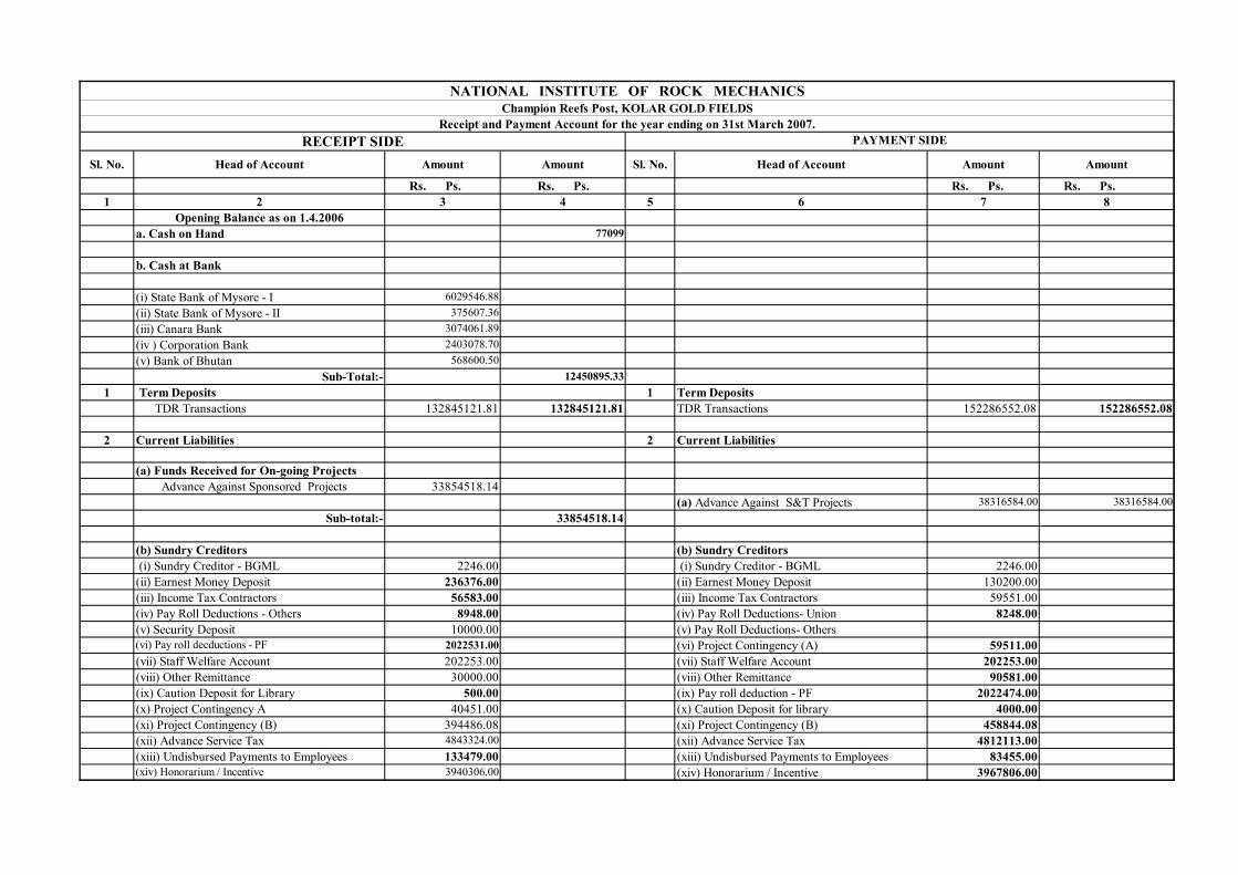
Sl. No. Head of Account Amount Amount Sl. No. Head of Account Amount Amount
Rs. Ps. Rs. Ps. Rs. Ps. Rs. Ps.1 2 3 4 5 6 7 8
Opening Balance as on 1.4.2006a. Cash on Hand 77099
b. Cash at Bank
(i) State Bank of Mysore - I 6029546.88(ii) State Bank of Mysore - II 375607.36(iii) Canara Bank 3074061.89(iv ) Corporation Bank 2403078.70(v) Bank of Bhutan 568600.50
Sub-Total:- 12450895.331 Term Deposits 1 Term Deposits
TDR Transactions 132845121.81 132845121.81 TDR Transactions 152286552.08 152286552.08
2 Current Liabilities 2 Current Liabilities
(a) Funds Received for On-going ProjectsAdvance Against Sponsored Projects 33854518.14
(a) Advance Against S&T Projects 38316584.00 38316584.00Sub-total:- 33854518.14
(b) Sundry Creditors (b) Sundry Creditors (i) Sundry Creditor - BGML 2246.00 (i) Sundry Creditor - BGML 2246.00(ii) Earnest Money Deposit 236376.00 (ii) Earnest Money Deposit 130200.00(iii) Income Tax Contractors 56583.00 (iii) Income Tax Contractors 59551.00(iv) Pay Roll Deductions - Others 8948.00 (iv) Pay Roll Deductions- Union 8248.00(v) Security Deposit 10000.00 (v) Pay Roll Deductions- Others(vi) Pay roll decductions - PF 2022531.00 (vi) Project Contingency (A) 59511.00(vii) Staff Welfare Account 202253.00 (vii) Staff Welfare Account 202253.00(viii) Other Remittance 30000.00 (viii) Other Remittance 90581.00(ix) Caution Deposit for Library 500.00 (ix) Pay roll deduction - PF 2022474.00(x) Project Contingency A 40451.00 (x) Caution Deposit for library 4000.00(xi) Project Contingency (B) 394486.08 (xi) Project Contingency (B) 458844.08(xii) Advance Service Tax 4843324.00 (xii) Advance Service Tax 4812113.00(xiii) Undisbursed Payments to Employees 133479.00 (xiii) Undisbursed Payments to Employees 83455.00(xiv) Honorarium / Incentive 3940306.00 (xiv) Honorarium / Incentive 3967806.00
NATIONAL INSTITUTE OF ROCK MECHANICSChampion Reefs Post, KOLAR GOLD FIELDS
Receipt and Payment Account for the year ending on 31st March 2007.RECEIPT SIDE PAYMENT SIDE

Sl. No. Head of Account Amount Amount Sl. No. Head of Account Amount Amount
Rs. Ps. Rs. Ps. Rs. Ps. Rs. Ps.1 2 3 4 5 6 7 8
RECEIPT SIDE PAYMENT SIDE
(xv) Sundry creditors for supplies 1341076.00 (xv) Sundry Creditors for Supplies 4609475.00(xvi)Accrued expenses (xvi) Accrued Expenses 248786.00(xvii)Defect liability 2863.00 (xv)Terminal benefits 254559.00(xviii) Terminal benefits 305566.00
(C) Prior period Adjustments 3000020.00
13570988.08 20014122.083 Current Assets 3 Current Assets
(a) Accrued Grants-in-aid received 14500000.00 14500000.00 (a) (a)Expenditure on R&D Projects 248625.00(b) Expenditure on running projects 6387453.48 6387453.48 (b) Expenditure on Sponsored Projects 6540825.40
(c) Expenditure on Testing 199734.00(d) Expenditure on Coal S&T 778962.00
Sub-Total:- 7768146.40
(b) Loans & Advanses (b) Loans & Advanses(a) Advance Remittances 189585.00 (a) Advance Remittances 187750.00(b) Deposits 2000.00 (b) Deposits(c) Material Advance - Staff 1310650.00 (c) Material Advance - Staff 1392832.00(d) Medical Advance 275462.00 (d) Medical Advance 314505.00(e) Employees Advance for Vehicle 88732.00 (e) Employees Advance for Vehicle(f) House building Advance 4900.00 (f) House building Advance(g) Advance - LTC 99406.00 (g) Advance - LTC 102542.00(h) Advance - Festival Adv. 28350.00 (h) Advance - Festival Adv. 27000.00(i) Travel Advance 1661957.00 (i) Travel Advance 1652456.00(j) Advance for Capital Material Purchase 6133659.40 (j) Advance for Capital Material Purchase 3832997.00(k) Contribution towards Ins. Premium 859.00 (k) Contribution towards Ins. Premium(l) Stoct Stationery Items 220233.00 (l) Stoct Stationery Items 229293.00(m) Imprest a/c 58693.00 (m) Imprest a/c 54500.00(n) Advances - others 12000.00 (n) Advances - others 12000.00(o) IT Receivables (o) IT receivable 746189.00
10086486.40 Sub-Total:- 8552064.00
4 Direct Expenses 4 Direct Expenses(a) Pay & Allowances (a) Pay & Allowances
(a) Salary of Staff & Officers 14319984.00(a) Travel Expenses - Others 50.00 (b) Bonus 61675.00(b) Medical Expenditure 1246.00 (c) Management Share of E.P.F. 1780176.00

Sl. No. Head of Account Amount Amount Sl. No. Head of Account Amount Amount
Rs. Ps. Rs. Ps. Rs. Ps. Rs. Ps.1 2 3 4 5 6 7 8
RECEIPT SIDE PAYMENT SIDE
(d) Premium on Gratuity Policy 370676.00(e) Tuition Fee/C.E.A 14590.00
Sub-total:- 1296.00 (f) Overtime Allowance 8688.00(g) L T C Expenditure 128876.00(h) Medical Expenditure 956854.00(i) Travel Expenditure 631895.00( j) Travel Expenditure - Foreign(k) Leave salary / pension contribution
Sub-total:- 18273414.00
(b) Administrative Expenses (b) Administrative Expenses
(a) Bank charges 50.00 (a) Recruitment Expenditure 131042.00(b)Security Charges 700.00 (b) Job Work for House Keeping 633836.00(c) Power & lighting 122875.00 (c)Audit Fee and Expenses 23017.00(d) Printing & Stationery 1836.00 (d) Advertisement Charges & Publicity 401441.00(e) Insurance 5613.00 (e) Security Wages 916257.00(f) Postal expenses 400.00 (f) Bank Charges 3407.00(g) Telephone & Telex 351.00 (g) Books & Periodicals 2068.00
131825.00 (h) Honorarium 34200.00(i) Incidentals/Office Expenses 13902.00(j) Insurance 9510.00(k) Training & Seminar 52603.00(l) Registration Fee ( VAT)(m) Postal Expenses 58488.00(n) Expenses on Peer Review Committee 313800.00(o) Printing & Stationery 82488.00(p) Telephone & Telex 49958.00(q) Power & Lighting 681516.00(r) Rates & Taxes 2500.00(s) G B Meeting Expenses 222987.00(t) Registration Fee(u) Registration Charges (Patent)(v) Membership fee 4995.00(w) Legal Hire 65530.00(x) Publications
Sub-Total:- 3703545.00
(c) Upkeep of Assets (c) Upkeep of Assets

Sl. No. Head of Account Amount Amount Sl. No. Head of Account Amount Amount
Rs. Ps. Rs. Ps. Rs. Ps. Rs. Ps.1 2 3 4 5 6 7 8
RECEIPT SIDE PAYMENT SIDE
(a) R&M - Vehicles 80840.00 80840.00 (a) R & M - Office & OtherEquipments 13283.00(b) R & M - Buildings 85725.00(c) R & M - Computers 97500.00(d) R & M - Vehicles 265407.00(e) R & M -furniture 3900.00(f) R & M - Electrical Works 10829.00
Sub-Total:- 476644.00
(d) Consumable & Contingency (d) Consumables & Contingency (a) Consumables 25000.00
(a) Contingency 2050.00 2050.00 (b) Contingency 21908.00 46908.00
5 Receipts 5 Non-Recurring Expenditure - Fixed Assets
(a) Receipts from Testing services 1529027.00 (a) Fixed Assets - Computers 412090.00(b) Income from completed projects 20088846.52 (b) Fixed Assets - Furniture 55375.00
(c) Fixed Assets - Lab Equipment 2989697.00(c) Income - Others 47814.00 (d) Fixed Assets - Technical Books 637485.44(d) Savings Bank 117429.00 (e) Fixed Assets - En. Geo. Lab 523391.00(e) Term Deposits 4398011.27 (f) Fixed Assets - Office equipment 0.00(f) Institute Development Fund 5865426.00 (g)Fixed asset - Water supply 0.00(g) House Rent and Sanitary etc., from the staff residing in Quarters
386891.00 (h)Fixed asset - Power supply 0.00
(h) Sale of tender documents 7506.00(i) Interest recovered on Interest Bearing Advances
9751.00 Sub-total:- 4618038.44
Sub-total:- 32450701.796 Institute Development Fund 60000000.00 60000000.00
6 Project RB0203 - THPA7 Patents 9000.00 9000.00
Expenditure adjusted 0.00 8 Closing Balance as on 31-03-2007
7 Institute Development Fund 60000000.00 60000000.00 a. Cash on Hand 20837 20837
b. Cash at Bank 2353420.03

Sl. No. Head of Account Amount Amount Sl. No. Head of Account Amount Amount
Rs. Ps. Rs. Ps. Rs. Ps. Rs. Ps.1 2 3 4 5 6 7 8
RECEIPT SIDE PAYMENT SIDE
(i) State Bank of Mysore - I -184944.9(ii) State Bank of Mysore - II 375607.36(iii) Canara Bank 981258.37(iv ) Corporation Bank 694634.7(v) Bank of Bhutan 486864.5
Total:- 316439275.03 Total:- 316439275.03
As per our Report of even date for G R S M & ASSOCIATES Chartered Accountants
Sd/- Sd/- Sd/- Sd/- (BIJU MATHEW) (V.P. MISHRA) ( ) (GOPALKRISHNA HEGDE)Finance & Accounts Officer Director Member PartnerPlace : BangaloreDate: 27th April 2007.

Annual Report 2006 – 07
58
SCHEDULE ACCOUNTING POLICIES AND NOTES ON ACCOUNT FORMING PART OF BALANCE SHEET AND INCOME & EXPENDITURE ACCOUNT FOR THE YEAR ENDING 31ST MARCH 2007.
1. ACCOUNTING POLICIES :-
A. Method of Accounting:
The Institute has maintained its accounts on cash basis, other than the below mentioned items which have been accounted on accrual basis.
1) Grant-in-aid for Capital and Recurring Expenditure. 2) Anticipated expenditure on projects towards printing and presentation of reports.
B. Fixed Assets:
Fixed Assets are capitalised at acquisition costs. C. Foreign Exchange Transactions: All imports of capital items by the Institute are through advance payments. Thus foreign
exchange transactions are entered in the books at the actual conversion rate. Hence, no
adjustments are required for fluctuation in exchange rates.
D. Revenue Recognition: 1. The income from Research & Development projects is recognised on completed contract
basis. 2. The Government Grant are accounted as Grants-in-Aid against the recurring expenditure are
recognized, when there is reasonable assurance that the same will be received on the basis of Sanction Letter by the Ministry of Mines which are received after the date of Balance Sheet.
E. Treatment of Government Grant: Grant received from Ministry of Mines under “Non-Plan” is utilised to meet “Pay & Allowances”. Grants received under ‘Plan” is utilised to meet capital expenditure. The Capital Grant received for ‘Plan’ is allocated to income over the period in the same proportion as the depreciation is charged on the assets purchased from the Capital Grant. Balance of capital grants appear as Deferred Government Grants in balance sheet under “Other Funds”.

Annual Report 2006 – 07
59
F. Retirement Benefits: The Institute has made arrangement with Life Insurance Corporation of India for payment of gratuity under the Cash Accumulation Group Gratuity Scheme. The premium paid under this head is charged to “Pay & Allowances”. Regarding Provident Fund accumulation, this Institute has been enrolled with the Employees Provident Fund Organization, Bangalore. The Institute’s contribution towards the Provident Fund is charged to “Pay & Allowances”. G. Depreciation: Depreciation is charged on straight-line basis as per the method specified by the Government of India, Department of Economic Affairs vide their letter No.4/24/63-GS dated 27th September 1968. As per this letter, depreciation on additions to Fixed Assets during the year has to be charged at full rate if they are put into use before 30th September, at half of the rate, if they are put into use between 1st October and 31st December and at one fourth of rate, if assets are put to use after 31st December of the relevant financial year. Upto 1998-99, the one-fourth rate of depreciation for assets put to use for less than three months was not implemented. This has been followed from 1999-2000 onwards. 2. NOTES ON ACCOUNTS: -
1. Capital Reserve represents value of assets transferred free of cost by BGML during 1988-89.
2. (a) The land on which the properties transferred during the year 1988-89 by BGML to the Institute has been retained in BGML books, subject to obtaining the direction from the Government of India, on the transfer of land and other formalities. As the Conveyance Deed for transfer of land and building to the Institute could not be executed, the Governing Body has approved the proposal for entering into lease agreement, instead. Necessary adjustments in the accounts if required will be done on execution of lease agreement.
3. The approval of the Central Government that the Institute is a notified association for
carrying on Research and Development activities under the section 35(1)(ii) of the Income Tax Act 1961, read with rule 6 of the Income Tax Rules 1962, was up to 31st March 2005. The application for renewal of the same has been submitted to the Income Tax Department and in under active consideration.
4. Provision for purchases of Capital equipments/assets have been made in the books of
accounts for 2006-07, since a definite liability has arisen before the close of the financial year due to issue of purchase orders after completion of the detailed tendering process.
5. A departmental enquiry on the misappropriation of funds has been instituted by the
Competent Authority of the institute and the criminal case relating to the misappropriation is also under process with the central investigating agency.
6. It is the normal practice of the Institute to charge off the expenses of manpower
component of respective S&T projects and transfer to a pool account of NIRM to meet out shortfall in “Pay & Allowances “ and other expenses.

Annual Report 2006 – 07
60
7. The balances of parties’ account are subject to confirmation.
8. The previous year figures have been re-grouped, re-classified or renamed wherever
necessary to confirm with the current year presentation.
9. The figures pre-fixed with the (+) or (-) under the column head “Variation during the year” in Balance Sheet as on 31-3-2007 represents the transaction carried out during the year including the value for written off adjustments and corrections.
Sd/- Sd/- (BIJU MATHEW) (V.P.MISHRA) Finance & Accounts Officer Director
Sd/- ( A. K. Ghose ) Member
Refer our report of even date For G R S M & ASSOCIATES Chartered Accountants Sd/- Place: Bangalore (GOPALKRISHNA HEGDE) Date: 27th April 2007 Partner
Annual Report 2006 – 07
61
ANNEXURE

Annual Report 2006 – 07
62
Appendix - 1
Organizational Chart of NIRM
General Body
Governing Body
Peer Review
Committee
Director
Finance & Accounts
Administration Technical Services
15 Specialized Scientific Disciplines under four Divisions
ROCK FRACTURE MECHANICS
ROCK ENGINEERING
EXCAVATION ENGINEERING
MINE DESIGN
Annual Report 2006 – 07
63
Appendix - 2
Members of the General Body
Chairman Sri J P Singh, IAS Secretary to the Government of India Department of Mines Ministry of Coal & Mines 3rd Floor, A Wing, Room no. 320 Shastri Bhawan, Dr Rajendra Prasad Road NEW DELHI – 110 001
Members Addl. Secretary to the Govt. of India Department of Mines Ministry of Coal & Mines 3rd Floor, A Wing, Room No. 326 Shastri Bhawan, Dr Rajendra Prasad Road NEW DELHI – 110 001
Sri Sujit Gulati, IAS Jt. Secretary & Financial Advisor Department of Mines Ministry of Coal & Mines 3rd Floor, A Wing, Room No. 321 Shastri Bhawan, Dr Rajendra Prasad Road NEW DELHI – 110 001
Sri Deepak Srivastava Director (Technical) Department of Mines Ministry of Coal & Mines 3rd Floor, D wing, Room No. 311 Shastri Bhawan Dr Rajendra Prasad Road NEW DELHI – 110 001
Sri B Bhattacharjee Director General of Mines Safety Directorate General of Mines Safety DHANBAD ─ 826 001 Jharkhand
Sri K P Lal Advisor (TPPC) Ministry of Mines CGO Complex, Block 11 (Eleven) 5th Floor, Lodhi Road NEW DELHI – 110 003
Dr A K Srivastava Director National Institute of Miners’ Health JNARDDC Campus, Opp. Wadi Police Stn Amravati Road, Wadi NAGPUR – 440 023
Sri S K Das Member (D&R) Central Water Commission Room no. 401(S) Seva Bhawan, R K Puram NEW DELHI – 110 066
Mrs Sudha Anchlia, IAS Chairperson-cum-Managing Director Gujarat Mineral Dev. Corp. Ltd. Khanij Bhavan, 132 ft Ring Road Near University Ground Vastrapur, AHMEDABAD - 380 052
Annual Report 2006 – 07
64
Sri K B Dubey Executive Director National Thermal Power Corp Ltd NTPC Bhawan, SCOPE Complex Core-5, 4th Floor 7 Industrial Area, Lodhi Road NEW DELHI – 110 003
Sri I D Paswan Director (Mines) Ministry of Mines & Geology Govt. of Jharkhand, Nepal House, Doranda RANCHI (Jharkhand)
Sri Ravi Shanker Retd. Director General, Geological Survey of India B-5, Sector K Aligunj LUCKNOW - 226 020
Prof A K Ghose Apartment No.3B 104, Regent Estate KOLKATA – 700 092 West Bengal
Sri B K P Sinha 1/15, HIG Rajasthan Housing Board Colony Govardhan Vilas UDAIPUR – 313 001
Director National Institute of Rock Mechanics Champion Reefs KOLAR GOLD FIELDS – 563 117
Secretary (Non-Member)
Mr A N Nagarajan Scientist, Technical Services Division National Institute of Rock Mechanics Champion Reefs KOLAR GOLD FIELDS – 563 117
Annual Report 2006 – 07
65
Appendix - 3
Members of the Governing Body
Chairman Sri J P Singh, IAS Secretary to the Government of India Department of Mines Ministry of Coal & Mines 3rd Floor, A Wing, Room no. 320 Shastri Bhawan, Dr Rajendra Prasad Road NEW DELHI – 110 001
Members Addl. Secretary to the Govt. of India Department of Mines Ministry of Coal & Mines 3rd Floor, A Wing, Room No. 326 Shastri Bhawan, Dr Rajendra Prasad Road NEW DELHI – 110 001
Sri Sujit Gulati, IAS Jt. Secretary & Financial Advisor Department of Mines Ministry of Coal & Mines 3rd Floor, A Wing, Room No. 321 Shastri Bhawan, Dr Rajendra Prasad Road NEW DELHI – 110 001
Sri Deepak Srivastava Director (Technical) Department of Mines Ministry of Coal & Mines 3rd Floor, D wing, Room No. 311 Shastri Bhawan Dr Rajendra Prasad Road NEW DELHI – 110 001
The Controller General Indian Bureau of Mines Indira Bhavan, Civil Lines NAGPUR - 440 001
The Advisor (Projects) Ministry of Coal 3rd floor, A Wing, Room no. 309 Shastri Bhawan NEW DELHI – 110 001
Dr S Sengupta Dy. Director General (PPM) - CHQ Geological Survey of India 27, Jawaharlal Nehru Road KOLKATA – 700 016
Sri K B Dubey Executive Director National Thermal Power Corp Ltd NTPC Bhawan, SCOPE Complex Core-5, 4th Floor 7 Industrial Area, Lodhi Road NEW DELHI – 110 003
Sri I D Paswan Director (Mines) Ministry of Mines & Geology Govt. of Jharkhand, Nepal House, Doranda RANCHI JHARKHAND
Annual Report 2006 – 07
66
Sri Ravi Shanker Retd. Director General, Geological Survey of India B-5, Sector K Aligunj LUCKNOW - 226 020
Prof A K Ghose Apartment No.3B 104, Regent Estate KOLKATA – 700 092 West Bengal
Sri B K P Sinha 1/15, HIG Rajasthan Housing Board Colony Govardhan Vilas UDAIPUR – 313 001
Director National Institute of Rock Mechanics Champion Reefs KOLAR GOLD FIELDS – 563 117
Secretary (Non-Member)
Mr A N Nagarajan Scientist, Technical Services Division National Institute of Rock Mechanics Champion Reefs KOLAR GOLD FIELDS – 563 117

Annual Report 2006 – 07
67
Appendix - 4
Members of the Peer Review Committee
Chairman Sri Ravi Shanker Director General (Retd.) Geological Survey of India B-5, Sector K Aligunj LUCKNOW - 226 020
Alternate Chairman / Member Prof AK Ghose Apartment No. 3B 104, Regent Estate KOLKATA – 700 092 West Bengal
Members Dr JL Jethwa St-403, Shewalkar Towers Daga Layout North Ambazari Road NAGPUR - 440 010
Sri BKP Sinha 1/15, HIG Rajasthan Housing Board Colony Govardhan Vilas UDAIPUR – 313 001
Dr AK Sinha Director of Mines Safety (S&T) Directorate General of Mines Safety DHANBAD - 826 001 Jharkhand
The Controller of Mines (CZ) Indian Bureau of Mines Indira Bhawan, Civil Lines NAGPUR - 440 001
Sri AK Chowdhury Head of the Department (S&T) Central Mine Plg & Design Instt Ltd Kanke Road RANCHI - 834 008 Jharkhand
Alternate Member Prof M Jawed Department of Mining Engineering Indian School of Mines DHANBAD -826 004 Jharkhand
Sri SK Das Member (D&R) Central Water Commission Room no. 401 (S) Seva Bhawan, RK Puram NEW DELHI – 110 066
Alternate Member Prof BK Raghu Prasad Chairman Department of Civil Engineering Indian Institute of Science BANGALORE - 560 012
Represented by : Sri Rajan Nair Chief Engineer, Monitoring (S) CWC, Jala Soudha; H M T BANGALORE – 560 031
Director National Institute of Rock Mechanics KOLAR GOLD FILEDS - 563 117
Secretary (Non-Member)
Mr AN Nagarajan Scientist, Technical Services Division National Institute of Rock Mechanics KOLAR GOLD FIELDS – 563 117
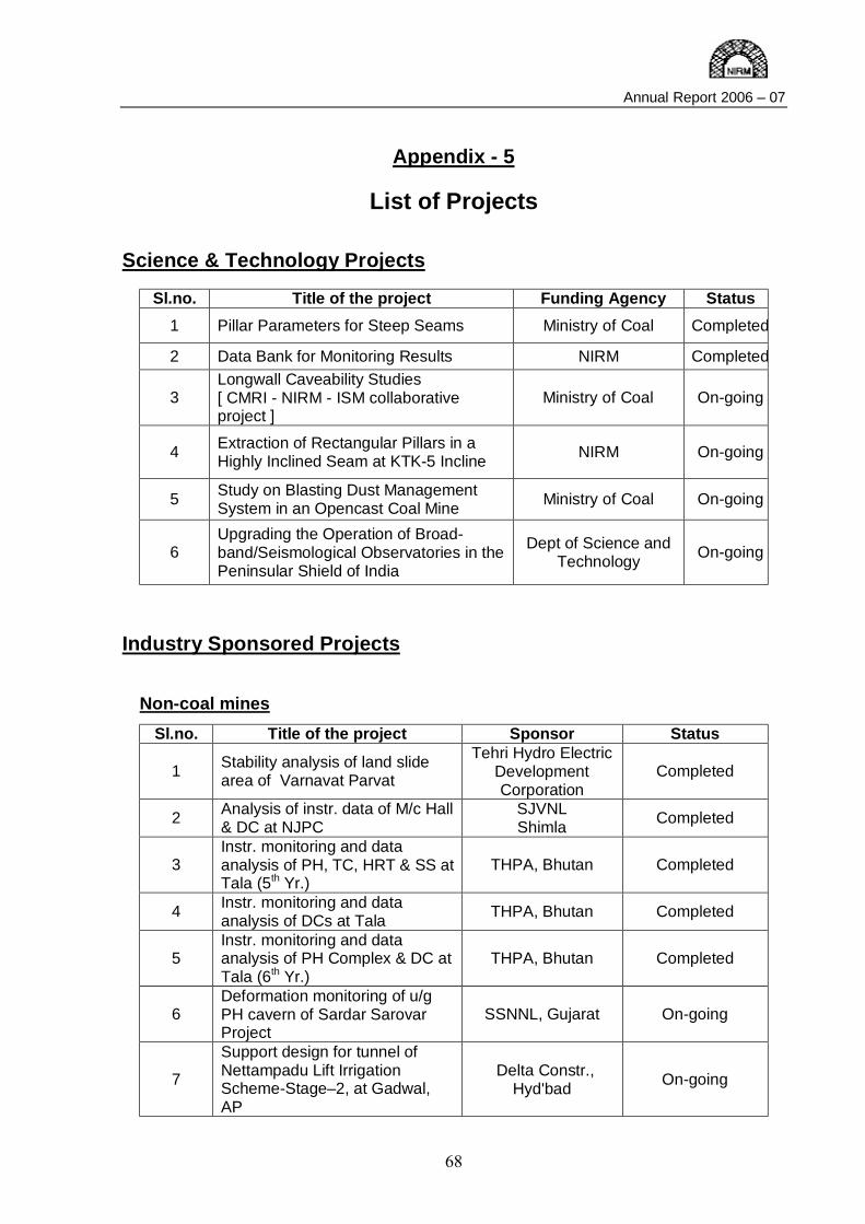
Annual Report 2006 – 07
68
Appendix - 5
List of Projects Science & Technology Projects
Sl.no. Title of the project Funding Agency Status 1 Pillar Parameters for Steep Seams Ministry of Coal Completed
2 Data Bank for Monitoring Results NIRM Completed
3 Longwall Caveability Studies [ CMRI - NIRM - ISM collaborative project ]
Ministry of Coal On-going
4 Extraction of Rectangular Pillars in a Highly Inclined Seam at KTK-5 Incline NIRM On-going
5 Study on Blasting Dust Management System in an Opencast Coal Mine Ministry of Coal On-going
6 Upgrading the Operation of Broad-band/Seismological Observatories in the Peninsular Shield of India
Dept of Science and Technology On-going
Industry Sponsored Projects
Non-coal mines Sl.no. Title of the project Sponsor Status
1 Stability analysis of land slide area of Varnavat Parvat
Tehri Hydro Electric Development Corporation
Completed
2 Analysis of instr. data of M/c Hall & DC at NJPC
SJVNL Shimla Completed
3 Instr. monitoring and data analysis of PH, TC, HRT & SS at Tala (5th Yr.)
THPA, Bhutan Completed
4 Instr. monitoring and data analysis of DCs at Tala THPA, Bhutan Completed
5 Instr. monitoring and data analysis of PH Complex & DC at Tala (6th Yr.)
THPA, Bhutan Completed
6 Deformation monitoring of u/g PH cavern of Sardar Sarovar Project
SSNNL, Gujarat On-going
7
Support design for tunnel of Nettampadu Lift Irrigation Scheme-Stage–2, at Gadwal, AP
Delta Constr., Hyd'bad On-going
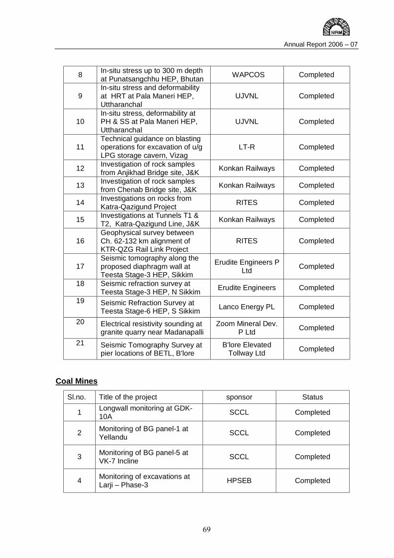
Annual Report 2006 – 07
69
8 In-situ stress up to 300 m depth at Punatsangchhu HEP, Bhutan WAPCOS Completed
9 In-situ stress and deformability at HRT at Pala Maneri HEP, Uttharanchal
UJVNL Completed
10 In-situ stress, deformability at PH & SS at Pala Maneri HEP, Uttharanchal
UJVNL Completed
11 Technical guidance on blasting operations for excavation of u/g LPG storage cavern, Vizag
LT-R Completed
12 Investigation of rock samples from Anjikhad Bridge site, J&K Konkan Railways Completed
13 Investigation of rock samples from Chenab Bridge site, J&K Konkan Railways Completed
14 Investigations on rocks from Katra-Qazigund Project RITES Completed
15 Investigations at Tunnels T1 & T2, Katra-Qazigund Line, J&K Konkan Railways Completed
16 Geophysical survey between Ch. 62-132 km alignment of KTR-QZG Rail Link Project
RITES Completed
17 Seismic tomography along the proposed diaphragm wall at Teesta Stage-3 HEP, Sikkim
Erudite Engineers P Ltd Completed
18 Seismic refraction survey at Teesta Stage-3 HEP, N Sikkim Erudite Engineers Completed
19 Seismic Refraction Survey at Teesta Stage-6 HEP, S Sikkim Lanco Energy PL Completed
20 Electrical resistivity sounding at granite quarry near Madanapalli
Zoom Mineral Dev. P Ltd Completed
21 Seismic Tomography Survey at pier locations of BETL, B'lore
B'lore Elevated Tollway Ltd Completed
Coal Mines
Sl.no. Title of the project sponsor Status
1 Longwall monitoring at GDK-10A SCCL Completed
2 Monitoring of BG panel-1 at Yellandu SCCL Completed
3 Monitoring of BG panel-5 at VK-7 Incline SCCL Completed
4 Monitoring of excavations at Larji – Phase-3 HPSEB Completed
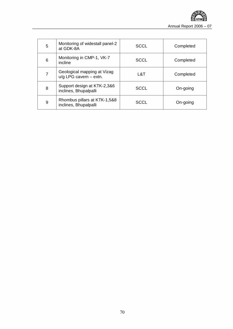
Annual Report 2006 – 07
70
5 Monitoring of widestall panel-2 at GDK-8A SCCL Completed
6 Monitoring in CMP-1, VK-7 incline SCCL Completed
7 Geological mapping at Vizag u/g LPG cavern – extn. L&T Completed
8 Support design at KTK-2,3&6 inclines, Bhupalpalli SCCL On-going
9 Rhombus pillars at KTK-1,5&8 inclines, Bhupalpalli SCCL On-going
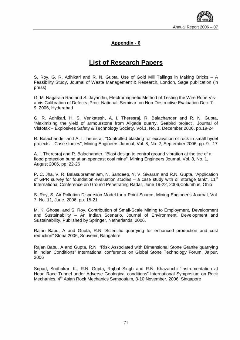
Annual Report 2006 – 07
71
Appendix - 6
List of Research Papers S. Roy, G. R. Adhikari and R. N. Gupta, Use of Gold Mill Tailings in Making Bricks – A Feasibility Study, Journal of Waste Management & Research, London, Sage publication (in press) G. M. Nagaraja Rao and S. Jayanthu, Electromagnetic Method of Testing the Wire Rope Vis-a-vis Calibration of Defects ,Proc. National Seminar on Non-Destructive Evaluation Dec. 7 - 9, 2006, Hyderabad G. R. Adhikari, H. S. Venkatesh, A. I. Theresraj, R. Balachander and R. N. Gupta, “Maximising the yield of armourstone from Aligade quarry, Seabird project”, Journal of Visfotak – Explosives Safety & Technology Society, Vol.1, No. 1, December 2006, pp.19-24 R. Balachander and A. I.Theresraj, "Controlled blasting for excavation of rock in small hydel projects – Case studies", Mining Engineers Journal, Vol. 8, No. 2, September 2006, pp. 9 - 17 A. I. Theresraj and R. Balachander, "Blast design to control ground vibration at the toe of a flood protection bund at an opencast coal mine", Mining Engineers Journal, Vol. 8, No. 1, August 2006, pp. 22-26 P. C. Jha, V. R. Balasubramaniam, N. Sandeep, Y. V. Sivaram and R.N. Gupta, “Application of GPR survey for foundation evaluation studies – a case study with oil storage tank”, 11th International Conference on Ground Penetrating Radar, June 19-22, 2006,Columbus, Ohio S. Roy, S. Air Pollution Dispersion Model for a Point Source, Mining Engineer’s Journal, Vol. 7, No. 11, June, 2006, pp. 15-21 M. K. Ghose, and S. Roy, Contribution of Small-Scale Mining to Employment, Development and Sustainability – An Indian Scenario, Journal of Environment, Development and Sustainability, Published by Springer, Netherlands, 2006. Rajan Babu, A and Gupta, R.N “Scientific quarrying for enhanced production and cost reduction” Stona 2006, Souvenir, Bangalore Rajan Babu, A and Gupta, R.N “Risk Associated with Dimensional Stone Granite quarrying in Indian Conditions” International conference on Global Stone Technology Forum, Jaipur, 2006 Sripad, Sudhakar. K., R.N. Gupta, Rajbal Singh and R.N. Khazanchi “Instrumentation at Head Race Tunnel under Adverse Geological conditions” International Symposium on Rock Mechanics, 4th Asian Rock Mechanics Symposium, 8-10 November, 2006, Singapore

Annual Report 2006 – 07
72
G D Raju, S. Gangadhara, H S Venkatesh and R Venugopala Rao, “Design of supports for an underground power house cavern using distinct element code”, National Conference on Civil Engineering Advances and Challenges, Ambala, India, 2006 G. R. Adhikari, N.K. Jain, S. Roy, A. I. Theresraj, R. Balachander, H.S. Venkatesh and R. N. Gupta, “Control measures for ground vibration induced by blasting at coal mines and assessment of damage to surface structures”, Journal of Rock Mechanics and Tunnelling Technology, Vol. 12, No. 1, 2006, pp. 4-19
Annual Report 2006 – 07
73
Appendix - 7
News Letter Mr. Sripad attended International training course on “Computational Geotechnics”, February 21-23, 2007 at IIT, Madras, Chennai. Mr. V. R. Balasubramaniam attended International training course on “Computational Geotechnics”, February 21-23, 2007 at IIT, Madras, Chennai. Dr. P. C. Jha delivered a lecture on “Application of Ground Penetrating Radar on mapping water logged workings” at CMPDI, Ranchi on November 30, 2006. Mr. Atul Gandhe, guided two B Tech projects as an external guide for the final year students of Mining Engineering Department of Golden Valley Institute of Technology, VTU on Influence of ground water on the stability of slopes in opencast iron ore mines, Optimum design of induced blasting in blasting gallery method. Mr. A. Rajan Babu is nominated as Member, Editorial Board of Stonedge, Journal on Indian Dimensional stone Industry. Mr. A. Rajan Babu is nominated as Member, Governing Board of the Stone Crafts Foundation, Jaipur, Ministry of Textiles, Government of India. Mr. A. Rajan Babu participated in the 7th International Granite and Stone fair Stona’2006 at Bangalore. Dr. C. Srinivasan, participated in a short term course on Strong Motion Instruments:Processing and use of its data organized by Department of Earthquake Engineering, Indian Institute of Technology, Roorkee, 21-26 August, 2006. Dr. C. Srinivasan guided one lecturer for the degree Master of Philosophy from Bharatidasan University, Tamil Nadu on the subject “The Source location of rockbursts in the mines of Kolar Gold Fields”. Dr. C. Srinivasan delivered a lecture on Technology Day (May 11, 2006) at R&D Division of BEML, Kolar Gold Fields on “ Tsunami Warning System”. Dr. C. Srinivasan, attended National Workshop on the Right to Information Act, 2005 conducted by Institute of Public Administration, Bangalore.16-17 March, 2007. Dr. H.S. Venkatesh attended the seminar on “Infrastructure for mining industry in Karnakata” on 01-09-2006 at Bangalore, organised by MEAI and Department of Mines & Geology.
Annual Report 2006 – 07
74
Appendix - 8
Distinguished Visitors to the Institute
1 Sri RH Khwaja Chairman & Managing Director Singareni Collieries Company Ltd. Hyderabad – 500 005
2 Sri Ravi Shanker Member, NIRM Governing Body & Chairman, NIRM PRC Formerly Director General, GSI
3 Prof AK Ghose Member, NIRM Governing Body & NIRM PRC Formerly Director, ISM
4 Sri BKP Sinha Member, NIRM Governing Body & NIRM PRC Formerly Director (Operations), HZL
5 Dr JL Jethwa Member, NIRM PRC Scientist-G (Retd.), CMRI
6 Sri Rajan Nair Chief Engineer, Monitoring (South) Central Water Commission Bangalore
7 Sri AK Chowdhary Member, NIRM PRC HOD (S&T), CMPDIL
8 Sri Deepak Srivastava Director (Technical) Ministry of Mines, NEW DELHI
9 Sri RK Gupta Chief Executive Officer Centre for Development of Stones JAIPUR – 302 005
10 Sri K Mohan Reddy Suptd. of Mines, GDK-8A Incline Singareni Collieries Company Ltd. Godavarikhani 8 Incline Colony
11 Sri SK Jain DGM (Geology) / Project Leader Head – Planning & Project Oil & Natural Gas Corpn. Ltd. NEW DELHI – 110 001
12 Honourable Mr Justice Bilal Nazki Chief Justice High Court of Andhra Pradesh Hyderabad
13 Mr Ashfaq Waheed Director of Mines Safety Hyderabad Region-1, DGMS

Annual Report 2006 – 07
75
Appendix – 9
Staff of NIRM
Director
Prof. R. N. Gupta (till May 31, 06) Dr. V. P. Mishra (June 06 onwards)
Director's Secretariat
Mr A Vijaya Kumar (till October 06) Mr G S Govinda Setty (from October 06)
Mine Design Dr V Venkateswarlu Mr S. K. Mohanty Mr C Nagaraj Mr Atul Gandhe Mr Sagaya Benedict Mr A Narayana Swamy Mr N Selvaraj Mr. S B Mishra (Project Scientist)
Engineering Geophysics Dr P C Jha Mr V R Balasubramaniam Mr Sandeep Nelliat Mr Y V Sivaram
Excavation Engineering Division
Dr G R Adhikari Dr H S Venkatesh Mr A I Theresraj Mr R Balachander
Dimensional Stone Technology Mr A Rajan Babu
Environmental Geotechnology Mr Surendra Roy Mr. M. Lakshmipathy
Rock Engineering Division Dr S Sengupta Mr D S Subrahmanyam Mr R K Sinha Mr D Joseph
Numerical modelling Mr Sripad Mr G Doraswamy Raju Mr. K. Sudhakar Mr. P. S. Varma
Rock Fracture & Materials Testing
Dr G M Nagaraja Rao Dr. S. Jayanthu (now with NIT, R’kela) Mr S Sathyanarayana Mr S Udayakumar Mr M Victor Mr Abdul Majeed Mr D Sampath Mr G Mohandoss Mr Syed Asgar Mr A Yesupadam
Seismology
Dr C Srinivasan Mr C Sivakumar Mr Y Ahnoch Willy
Technical Services
DR. C. Srinivasan, HOD (addl charge) Mr A N Nagarajan Mr. A. Vijaikumar Mr. N. Sounderrajan
Library Mrs S Lourdu Mary
Acounts & Administration
Dr. P. C. Jha, COA (addl. Charge) Mr M R Muralidharan Mr Y L Visweswaraiah Mr Biju Mathew (now with ERNET, New Delhi) Mr J V Sastry Mr N Jothiappa Mr S Ravi Mr J Raja Mrs C V Lalitha Mr V Suresh Mr P Venkata Reddy Mr M S. Nagaraja Mr T Anjaneyappa

jk“Vªh; fÓyk ;kaf=dh laLÉku NATIONAL INSTITUTE OF ROCK MECHANICS
(An Autonomous Research Institute, under Ministry of Mines, Govt of India)
Champion Reefs, Kolar Gold Fields - 563 117 Karnataka, INDIA
Phone (office) : 91 - 8153–275006 to 275009 Phone (Director) : 91 - 8153–275000 (office) Phone (COA) : 91-8153-275003 Fax : 91 - 8153 – 275002 e-mail : [email protected]; [email protected]
Web site : http://www.nirm.in Office Timings
The Institute works from Monday to Saturday. The working schedule on week days is : 9:00 AM to 5:30 PM (lunch break from 1:00 PM to 2:00 PM)
On Saturdays, the Office is open up to 1:00 PM only. The Institute remains closed on Second Saturday of every month.
Important contact phone numbers
NIRM Office EPABX : 08153 – 275006-275009
Office No.
Vacant Director 275000 (Direct)
Dr V Venkateswarlu Mine Design Ext.29
Dr GR Adhikari Excavation Engineering Ext.31
Dr S Sengupta Rock Engineering Ext.28
Dr GM Nagaraja Rao Rock Fracture Mechanics Ext.39
Dr P C Jha Engg. Geophysics/ COA Ext.24
Dr. C. Srinivasan Seismology/ Tech. Services Ext.38/40
Vacant Finance & Accounts Officer Ext.35/26
Mr G S Govind Setty Tech Secretary to Director Ext.42

Our Mission
Rock mechanics design for better safety, economy and conservation
jk“Vªh; fÓyk ;kaf=dh laLÉku National Institute of Rock Mechanics
KOLAR GOLD FIELDS
Phones: 08153 – 275000 to 09; Fax: 08153 – 275002 Email: [email protected] Web: http://www.nirm.in


![¤ B ] o § A» R o e » U B ¼ d U ¹ v Ø w Æ « B P 1 1 4 . 2 Z 2 1 3 9 4 2 9 7 . 2 6 4 9 1 0 3 6 J B T A ¹ Ø ½ ± µ Ç Ç Ç Ç Ç Ç Ç Ç Ç Ç Ç Ç Ç Ç Ç Ç Ç Ç Ç](https://img.dokumen.tips/doc/110x75/5ea672a97f8b0c2e316db4e1/-b-o-a-r-o-e-u-b-d-u-v-w-b-p-1-1-4-2-z-2-1-3-9-4-2.jpg)


![Kirkos [for sax quartet] - Free-scores.com · Sax Soprano Sax Contralto Sax Tenore Sax Baritono Ç Ç M M Con spirito Ç Ç Ç Ç Ç Ç Ç Ç » M](https://img.dokumen.tips/doc/110x75/5b3c74aa7f8b9a1a678f99e9/kirkos-for-sax-quartet-free-sax-soprano-sax-contralto-sax-tenore-sax-baritono.jpg)