Embed Size (px)
Citation preview

Quick Installation Guide
Manual Part Number 32-0356-048 Rev0, July 18, 2018© 2018 Teledyne Technologies Incorporated. All rights reserved. Printed in USA.
Oils 7400 SeriesHomogenizing Autosampler

2
Preparing for InstallationThis document shows you how to install the hardware components of the Teledyne CETAC Oils 7400 homogenizing autosampler. See the Oils 7400 Series Operators Manual (on the CD) for instructions on installing the software and information on using and caring for the system.
System Components
FIGURE 1 Oils 7400 Autosampler—Front View
FIGURE 2 Z-Drive Assembly—Right Side View
Autosampler Head
Stirring Paddle
Sample Probe
Sample Tray
Standards Vials
Sample Vial Racks
Rinse Station
Arm
Power Indicator Lamp
Autosampler Base
Cable Chain
Drip Cup
Z Drive Assembly
Z
YX
Probe/Stirrer Block
Stirrer Motor

3
FIGURE 3 Oils 7400 Autosampler—Back View
Equipment Required
You will need to choose a sample probe and sample racks appropriate for your application.
The probe/stirrer block determines the spacing between the probe and stirrer; this spacing must match the vial-to-vial spacing of the rack which is in use.
You will need to supply the following items:
Liquid waste containers, 10 liters or larger Solvent bottles Computer
Choosing a Location
Position the autosampler on a sturdy surface as close as possible to the ICP nebulizer.
CAUTION
LIFTING HAZARD
Two people are required to lift the autosampler. Lifting should be done with a person situated on either side of the instrument. Lifting without assistance may cause injury.
NOTE
Keep the original packaging for use in case the product ever needs to be returned or shipped to another location.
Installing the ASX-7x00 Dashboard Software1 On the included CD, double-click the ASX Dashboard installation file and follow the prompts
to complete the installation.
You do not need to run the software yet. The installation includes a USB driver which Windows should automatically find when you connect the autosampler to the PC.
Power SwitchSerial Ports Ethernet Port
Power Connector
Z-Drive Connector
Peristaltic Pump (Coolants)
Stirrer Connector
Auxiliary PortUSB Port
Peristaltic Pump (Oils)
Rinse Station Fittings (Coolants)Rinse Station Fittings (Oils)

4
Mounting the Tray 1 Place the tray on the base of the autosampler.
Make sure the locating pins on the tray fully seat into the locating holes in the base.
Installing the StirrerWhen the autosampler is used for oils, install the stirrer paddle. When the autosampler is used for coolants, the stirrer paddle should be removed (or replaced with the optional coated coolants stirrer paddle).
1 Locate the oils stirrer paddle.
FIGURE 4 Stirrer Paddle for Oils
2 Press the stirrer paddle into the hole on the bottom of the stirrer motor.
FIGURE 5 Inserting the Stirrer Paddle
3 Place the stirrer motor into the larger hole in the probe/stirrer block on the Z-drive.
FIGURE 6 Placing the Stirrer Motor

5
4 Tighten the two thumbscrews.
FIGURE 7 Securing the Stirrer
Installing and Adjusting the Sample Probe1 Choose the appropriate probe for your application.
2 Locate the two thumbscrews which are supplied with the probe.
3 Guide the probe straight down through the smaller hole in the Z-drive.
4 Adjust the height of the probe so that the tip of the probe is level with the tip of the stirrer paddle.
FIGURE 8 Probe Level With Stirrer Paddle

6
5 Tighten the thumbscrews.
FIGURE 9 Installing the Probe
6 Check the position of the sample tubing.
Always position the sample transfer tubing so that it does not pull on the probe. The tubing should naturally curve away from the probe so that it won't rub or get caught. Be sure to check that the tubing will not be stretched and will not snag on an obstacle when the probe is moved to the far corner sample positions.
Connecting the Rinse StationThe rinse station is mounted at the left end of the autosampler.
For coolants samples, the rinse solution is typically deionized water or a dilute acid rinse such as 1% HNO3. For oils samples, the rinse solution is typically a solution from the kerosene family.
The inlet of the rinse station is at the bottom of the rinse station. The rinse solution flows from the bottom to the top.
Waste Rinse Solution
In most cases, rinse solution will be “recycled” by returning it to the rinse solution bottle. If necessary, rinse solution can be pulled from a fresh bottle and used solution drained to a waste container. Remember to label the waste container according to your laboratory policy and local regulations.
CAUTIONEnsure that the tubing outlet is placed so that it will remain above the surface of the liquid in the waste container. If the end of the tube is immersed, the waste solution might back up and overflow.
Tubing Considerations
Verify that the supplied tubing material is compatible with the rinse solution you are using. Clear Superthane® tubing is supplied (except for the peristaltic pump tubing cartridge). Refer to the Oils 7400 Spare Parts and Accessories Catalog or contact CETAC if you need different tubing material.
The fittings on the rinse station and on the peristaltic pump use ⅛ inch (3.2mm) ID tubing.
Carefully press the tubing straight on to the fittings to avoid breaking the fittings. If you find it difficult to get a good connection to the rinse station, remove the rinse station and press

7
the tubing firmly so that it completely covers the barb of the fitting. It helps to use your other hand to apply counter-pressure.
Pumped Drain Arrangement
Normally, the peristaltic pump channel which is closest to the autosampler chassis is used to pull liquid out of the rinse station and the channel which is farther from the autosampler is used to feed in the fresh rinse solution.
To connect the rinse station using the pumped drain, complete the following steps. Repeat this procedure for both the “Oils” and “Coolants” peristaltic pump.
1 Connect up to 1.8 meters of tubing from the outlet fitting of the pump (the lower fitting of the channel closest to the autosampler) to the waste container.
3.33
FIGURE 10 Connecting the Waste Line
Ensure that the tubing outlet is placed so that it will remain above the surface of the liquid in the waste container. If the end of the tube is immersed, the waste solution might back up and overflow.
2 Cut two pieces of tubing to go between the peristaltic pump and the rinse station; ensure that the tubing is long enough to reach without any sharp bends or kinks. For the Oils side, the tubing should be about 25 cm (10 inches) long; for the Coolants side, it should be about 28 cm (12 inches) long.
FIGURE 11 Cutting Tubing
8
3 Connect one of the pieces of tubing from step 2 to the input (top) of the pump channel.
4 Connect the other end of the tubing to the outlet (upper) fitting of the rinse station.
The “Coolants” peristaltic pump should be connected to the blue side of the rinse station and the “Oils” pump should be connected to the green side of the rinse station.
FIGURE 12 Connecting the Rinse Station Drain (Oils Side Is Shown)
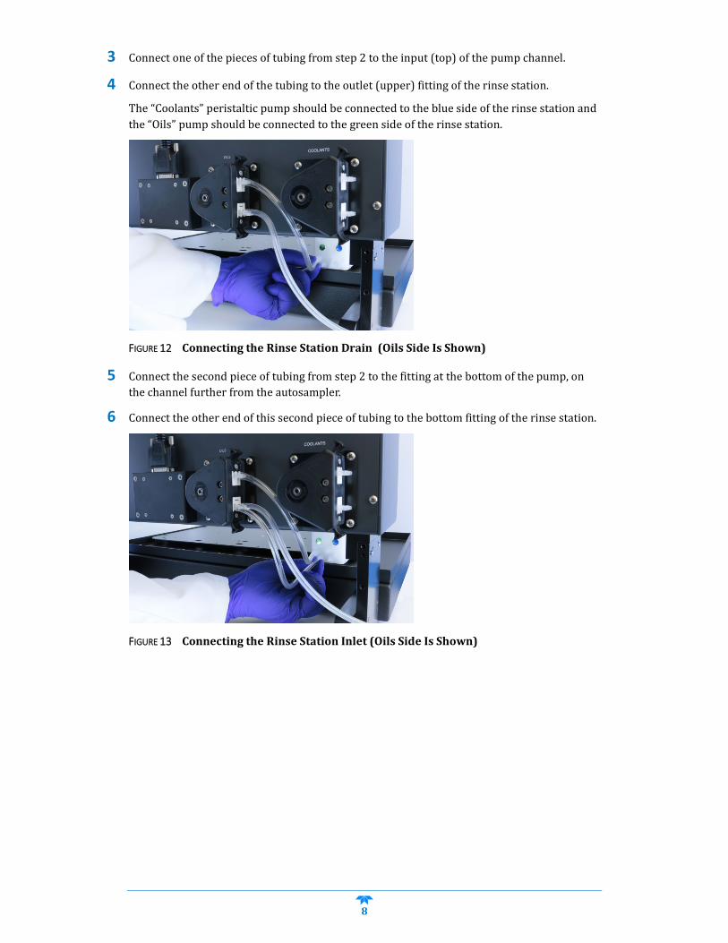
5 Connect the second piece of tubing from step 2 to the fitting at the bottom of the pump, on the channel further from the autosampler.
6 Connect the other end of this second piece of tubing to the bottom fitting of the rinse station.
FIGURE 13 Connecting the Rinse Station Inlet (Oils Side Is Shown)

9
7 Use an appropriate length of the tubing to connect the rinse solution source to the fitting at the top of this channel.
FIGURE 14 Completed Rinse Station Tubing for the Oils Side
Assembling and Placing the Sample Vial RacksSome styles of sample vial racks are shipped unassembled. You can easily assemble them without using tools.
WARNING
PUNCTURE HAZARD
Never attempt to load, unload or reposition the sample vial rack or sample vial while the autosampler is operating. The sample probe may move unexpectedly and cause an injury.
1 Before loading or unloading any sample vial racks on the sample tray, park the sampling arm and probe in the home position. The home position is the initial position at power up.
2 If necessary, assemble the racks as shown in the instructions included with each rack.
3 Place the first sample vial rack at the extreme left-hand side of the sample tray. Place the next sample vial rack to the right of the first rack, and so forth.
Connecting to the Analytical Instrument’s Sample PortYou can connect the autosampler directly to a sample introduction peristaltic pump and then to a nebulizer or other sample introduction device.
From Rinse Solution Source
To Waste Container

10
One end of the sample transfer tubing is preconnected to the sample probe.
The transfer tubing should be long enough so that it there will be no strain on the tubing connectors even when the sample probe is at the position farthest from the analytical instrument.
1 Determine the length of the sample transfer tubing you need, and cut it to size.
2 Connect the free end of the sample transfer tubing to the inlet of the analytical instrument’s peristaltic pump.
Connecting the Autosampler to the Power SupplyThe autosampler is powered by the supplied external desktop "brick" power supply. Ensure that you position the autosampler so that the location where the power supply cord plugs into it is easily accessible (is not blocked) and it can be quickly disconnected if needed. In case of hazard, the system should be disconnected from the power source.
1 Turn the power switch on the autosampler OFF.
2 Check the plug on the power cord to verify that it is of the correct type for your country.
3 Plug the power cord into a power outlet.
4 Plug the power cord into the power supply.
FIGURE 15 Power Supply
5 Plug the power supply into the 24 V connector on the autosampler.
6 Turn the power switch on the autosampler ON.
It is important to use the appropriate power cord for your country.
Power Cord to Grounded AC Power OutletTo POWER
Connector on Autosampler

11
Connecting the Autosampler to the Host ComputerSoftware on the host computer controls both the analytical instrument and the autosampler. The USB interface is the standard configuration. A virtual COM port is created so that the connection looks like a standard RS-232 serial port to the host PC software. If necessary, you may also use a serial (RS-232) cable.
NOTE:
Use either a USB cable or a serial cable, but not both. The serial port will not function when a USB cable is connected.
1 Power on both the computer and the autosampler.
2 Plug one end of the cable into the host computer's USB port and the other end into the autosampler’s USB port.
Windows will automatically find the driver which was installed with the ASX-7x00 Dashboard software.
3 When driver installation is complete, make a note of which COM port number was assigned. The COM port number may be displayed in a “bubble” in the lower right corner of the screen.

12
Switching Between Coolant and Oil Samples1 Move the rinse station to the appropriate position. The status LED on the front of the
autosampler will show green for the oils position or blue for the coolants position.
FIGURE 16 Rinse station in coolants (left) and oils (right) position.
2 Moving the rinse station will automatically switch to the appropriate peristaltic pump on the back of the autosampler. Visually verify that the tubing is directed to the correct rinse supply and waste containers.
3 Replace the sample probe with the appropriate version.
4 Replace the stirring paddle with the appropriate version. For oils, use the oils paddle. For coolants, remove the paddle or use the optional coolants paddle (identified by a black band).
5 If using an ASXPRESS PLUS Rapid Sample Introduction System, either replace the valve and tubing, or use a second valve/pump module which has been set up for oils or coolants.