Embed Size (px)
Citation preview

A welding review published by The Esab Group Vol. 54 No. 3 1999
Oil & Gas
Svetsaren 3,1999 2000-01-20 13.11 Sidan 1
Svetsaren No.3 1999
Contents Vol. 54 No. 3 1999Development of matching composition supermartensitic stainless steel welding consumablesNewly developed supermartensitic metal-cored wires produce high-quality welds with properties which match requirements.
Linepipe welding beyond 2000Pipeline construction continues to grow despite low oil prices and slow world economicgrowth.
Tanko know-how in double-headed tanksThe first application in a series of double-head tanks delivered to be used for low-temperature application (LNG).
Welding engineering standardisation—international and EuropeanA review of international and European standards for welding.
Stubends & SpatterProduct briefs.
Filler alloy selection for aluminium weldingHow to choose the most suitable filler alloy for aluminium welding.
Precision laser gantryAustrian Voest Alpine Stahl Linz GmbH gets more precise cutting and a smaller amount offinishing work with laser cutting systems from ESAB-Hancock.
Plasma welding aluminiumPlasma welding is the process for the third millennium.
Successful TIG welding of umbilicals for the oil industryUmbilicals made of stainless steels developed by Kvaerner Oilfield Products AS in Norway.
The millennium bug or the Y2k problemWhy is it a problem and how will it affect us all?
Strip cladding replaces sheet liningReport on an unusual application for strip cladding in the pulp and paper industry.
2
Articles in Svetsaren may be reproduced without permission but with an acknowledgement to Esab.
PublisherBertil Pekkari
EditorLennart Lundberg
Editorial committeeKlas Weman, Lars-Göran Eriksson, Johnny Sundin, Johan Elvander, Dag Jacobsen,
Bob Bitsky, Stan Ferree, Ben Altemühl, Gerd Peters, Susan Fiore
AddressESAB AB, Box 8004, S-402 77 Göteborg, Sweden
Internet addresshttp://www.esab.comE-mail: [email protected]
Printed in Sweden by Skandia-Tryckeriet, Göteborg
A welding review published by The Esab Group No. 3 • 1999
3
8
11
12
16
20
23
26
29
30
33
Refinery by night in Göteborg, Sweden.Photo: Anders Kristensson, Bildbyrån iGöteborg AB.
Svetsaren 3,1999 2000-01-20 13.17 Sidan 2

The development ofmatching compositionsupermartensitic weld-ing consumables is pre-sented. It is shown thatthe newly developedsupermartensitic metal-cored wires OK Tubrod15.53 and OK Tubrod15.55 produce high-quality welds with prop-erties which match re-quirements when usedwith realistic fabricationwelding procedures.
IntroductionDuplex ferritic-austenitic stain-less steels have been used forsome years to combat corrosionproblems in the oil and gas in-dustry. New weldable supermar-tensitic stainless steels are, how-ever, finding increasing applica-tion as an economical option, of-fering corrosion performancebetween that of carbon steel andduplex stainless steel (refs. 1-5).These steels offer sufficient cor-rosion resistance for sweet andmildly sour environments in com-bination with high strength andgood low-temperature toughnessand are specifically designed forfield welding where the use oflong-term post-weld heat treat-ment (PWHT) is impracticable(ref. 6). The carbon content is re-
duced to extra low levels in orderto obtain the necessary propertiesin the as-welded condition andelements such as Mo and Cu areadded for improved corrosion re-sistance.
The choice of filler materialand welding procedure is largelygoverned by the need 1 to match parent material
strength,2 to achieve sufficient toughness,3 to keep hardness at an accept-
able level,4 to match corrosion resistance
and 5 to avoid PWHT.
Although good results havebeen obtained with soft marten-sitic 13%Cr 4%Ni + Mo alloysand duplex or superduplex con-sumables (refs. 2-4), supermarten-sitic consumables offer a numberof advantages. Not only are theweld metal strength, hardness andcorrosion resistance similar tothose of the parent material. Theweld metal and parent materialalso respond similarly to PWHTand thereby eliminate the risk ofweld metal embrittlement whichcan occur in the case of superdu-plex weld metals. A further ad-vantage is the decreased risk ofdistortion thanks to the lowerthermal expansion coefficient ofsupermartensitic weld metals ascompared to duplex weld metals.Complications related to the dilu-tion of filler metal with parentmaterial are also avoided ifsupermartensitic consumables areused.
The aim of the present study isto show that “matching” composi-tion supermartensitic consum-ables can be formulated and canproduce largely martensitic weldmetals. It is also demonstratedthat supermartensitic consum-ables can be used with realisticfabrication welding procedures toproduce high-quality welds withsatisfactory properties.
Chemical composition,microstructure and mechanical propertiesExperimental weldsIn the very early stages of devel-opment, it became evident thatthe weld metal chemical composi-tion strongly influenced the mi-crostructure and mechanicalproperties. As a first step, chemi-cal compositions and mechanicalproperties for a large number ofexperimental weld metals weretherefore determined and corre-lated to microstructure, transfor-mation characteristics and weld-ing procedure (see also refs. 7 and 8).
An evaluation showed that the very low C and N content(<0.01%), essential to obtaingood toughness and low hardness,could be obtained most reliablywith metal-cored wires. Further-more, metal-cored wires are idealfor submerged arc (SAW), tung-sten inert gas (TIG) and metal in-ert/active gas welding (MIG/MAG), thereby offering flexibil-ity and high productivity.
Svetsaren No.3 1999 3
Development of matching composition supermartensitic
stainless steel welding consumables
Leif Karlsson and Solveig Rigdal, ESAB AB, Göteborg, Sweden and Wouter Bruins and Michael Goldschmitz, FILARC Welding Industries B.V., Utrecht, the Netherlands
Svetsaren 3,1999 2000-01-20 13.33 Sidan 3
Mechanical properties Weld metal yield and tensilestrength were generally well abo-ve the typical values for super-martensitic parent materials (refs.3, 4 and 6). The exception wasweld metals with a large volume
fraction of retained austenite(>25%) and with a yield strengthbelow the minimum level of 550MPa required for X80 gradesteels. Both the yield and ultimatetensile strength were lower trans-verse to welds in supermartensiticplate material than along weldsand fracture always occurred inthe parent material. Elongationwas typically in the range of 15-20%, regardless of compositionand welding method.
Maximum hardness correlatedwell to the C content and PWHT(5 min/620°C) was effective in re-ducing hardness (cf. refs. 1, 3, 4and 6, for example). A maximumas-welded hardness of approxi-mately 350 HV10 could be ob-tained if the C content was keptbelow 0.013%C.
Significant amounts of ferritewere found to be detrimental to
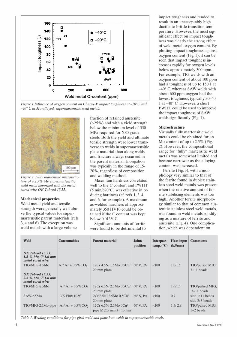
impact toughness and tended toresult in an unacceptably highductile to brittle transition tem-perature. However, the most sig-nificant effect on impact tough-ness was clearly the strong effectof weld metal oxygen content. Byplotting impact toughness againstoxygen content (Fig. 1), it can beseen that impact toughness in-creases rapidly for oxygen levelsbelow approximately 300 ppm.For example, TIG welds with anoxygen content of about 100 ppmhad a toughness of up to 150 J at–40° C, whereas SAW welds withabout 600 ppm oxygen had thelowest toughness, typically 30–40J at –40° C. However, a shortPWHT could be used to improvethe impact toughness of SAWwelds significantly (Fig. 1).
MicrostructureVirtually fully martensitic weldmetals could be obtained for anMo content of up to 2.5% (Fig.2). However, the compositionalrange for “fully“ martensitic weldmetals was somewhat limited andbecame narrower as the alloyingcontent was increased.
Ferrite (Fig. 3), with a mor-phology very similar to that ofthe ferrite found in duplex stain-less steel weld metals, was presentwhen the relative amount of fer-rite stabilising elements was toohigh.. Another ferrite morpholo-gy, similar to that of common aus-tenitic stainless steel weld metals,was found in weld metals solidify-ing as a mixture of ferrite andaustenite (Fig. 4). One complica-tion, which was dependent on
4 Svetsaren No.3 1999
–40°C
–20°CIm
pact
toug
hnes
s (J
)
Weld metal O-content (ppm)
Figure 1.Influence of oxygen content on Charpy-V impact toughness at –20°C and–40° C in Mo-alloyed supermartensitic weld metals.
Figure 2. Fully martensitic microstruc-ture of a 2.5% Mo supermartensiticweld metal deposited with the metal-cored wire OK Tubrod 15.55.
Weld Consumables Parent material Joint/ Interpass Heat input Commentsposition temp. (°C) (kJ/mm)
OK Tubrod 15.53:1.5 % Mo, B 1.6 mm metal cored wire:TIG/MIG-1.5Mo Ar/ Ar + 0.5%CO2 12Cr 4.5Ni 1.5Mo 0.5Cu/ 60°V, PA <100 1.0/1.5 TIG/pulsed MIG,
20 mm plate 3+11 beadsOK Tubrod 15.55:2.5 % Mo, B 1.6 mm metal cored wire:TIG/MIG-2.5Mo Ar/ Ar + 0.5%CO2 12Cr 6.5Ni 2.5Mo 0.5Cu/ 60°V, PA <100 1.0/1.5 TIG/pulsed MIG,
20 mm plate 3+11 beadsSAW-2.5Mo OK Flux 10.93 2Cr 6.5Ni 2.5Mo 0.5Cu/ 60°X, PA <100 0.7 side 1: 11 beads
20 mm plate side 2: 3 beadsTIG/MIG-2.5Mo-pipe Ar/ Ar + 0.5%CO2 12Cr 6.5Ni 2.5Mo 0Cu/ 60°V, PA <100 1.5/ 2.8 TIG/pulsed MIG,
pipe B 255 mm, t= 13 mm 1+2 beads
Table 1. Welding conditions for pipe girth weld and plate butt welds in supermartensitic steels.
Svetsaren 3,1999 2000-01-21 11.07 Sidan 4
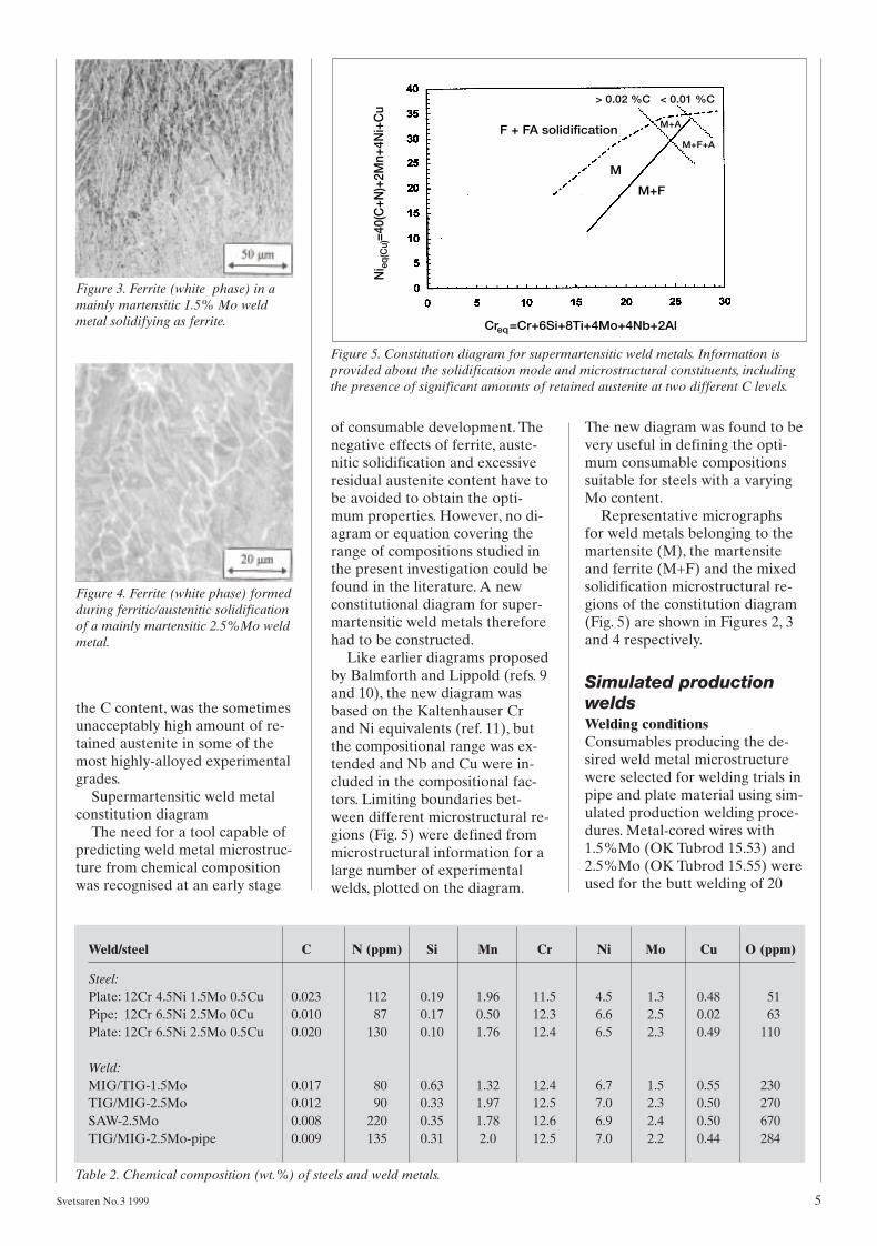
the C content, was the sometimesunacceptably high amount of re-tained austenite in some of themost highly-alloyed experimentalgrades.
Supermartensitic weld metalconstitution diagram
The need for a tool capable ofpredicting weld metal microstruc-ture from chemical compositionwas recognised at an early stage
of consumable development. Thenegative effects of ferrite, auste-nitic solidification and excessiveresidual austenite content have tobe avoided to obtain the opti-mum properties. However, no di-agram or equation covering therange of compositions studied inthe present investigation could befound in the literature. A newconstitutional diagram for super-martensitic weld metals thereforehad to be constructed.
Like earlier diagrams proposedby Balmforth and Lippold (refs. 9and 10), the new diagram wasbased on the Kaltenhauser Crand Ni equivalents (ref. 11), butthe compositional range was ex-tended and Nb and Cu were in-cluded in the compositional fac-tors. Limiting boundaries bet-ween different microstructural re-gions (Fig. 5) were defined frommicrostructural information for alarge number of experimentalwelds, plotted on the diagram.
The new diagram was found to bevery useful in defining the opti-mum consumable compositionssuitable for steels with a varyingMo content.
Representative micrographsfor weld metals belonging to themartensite (M), the martensiteand ferrite (M+F) and the mixedsolidification microstructural re-gions of the constitution diagram(Fig. 5) are shown in Figures 2, 3and 4 respectively.
Simulated productionweldsWelding conditionsConsumables producing the de-sired weld metal microstructurewere selected for welding trials inpipe and plate material using sim-ulated production welding proce-dures. Metal-cored wires with1.5%Mo (OK Tubrod 15.53) and2.5%Mo (OK Tubrod 15.55) wereused for the butt welding of 20
Svetsaren No.3 1999 5
Figure 3. Ferrite (white phase) in amainly martensitic 1.5% Mo weldmetal solidifying as ferrite.
Figure 4. Ferrite (white phase) formedduring ferritic/austenitic solidificationof a mainly martensitic 2.5%Mo weldmetal.
Figure 5. Constitution diagram for supermartensitic weld metals. Information isprovided about the solidification mode and microstructural constituents, includingthe presence of significant amounts of retained austenite at two different C levels.
Weld/steel C N (ppm) Si Mn Cr Ni Mo Cu O (ppm)
Steel:Plate: 12Cr 4.5Ni 1.5Mo 0.5Cu 0.023 112 0.19 1.96 11.5 4.5 1.3 0.48 51Pipe: 12Cr 6.5Ni 2.5Mo 0Cu 0.010 87 0.17 0.50 12.3 6.6 2.5 0.02 63Plate: 12Cr 6.5Ni 2.5Mo 0.5Cu 0.020 130 0.10 1.76 12.4 6.5 2.3 0.49 110
Weld:MIG/TIG-1.5Mo 0.017 80 0.63 1.32 12.4 6.7 1.5 0.55 230TIG/MIG-2.5Mo 0.012 90 0.33 1.97 12.5 7.0 2.3 0.50 270SAW-2.5Mo 0.008 220 0.35 1.78 12.6 6.9 2.4 0.50 670TIG/MIG-2.5Mo-pipe 0.009 135 0.31 2.0 12.5 7.0 2.2 0.44 284
Table 2. Chemical composition (wt.%) of steels and weld metals.
Cr =Cr+6Si+8Ti+4Mo+4Nb+2Al eq
Ni
=40(
C+N
)+2M
n+4N
i+C
ueq
(Cu)
F + FA solidification
> 0.02 %C < 0.01 %C
M
M+F
M+A
M+F+A
Svetsaren 3,1999 2000-01-21 11.08 Sidan 5
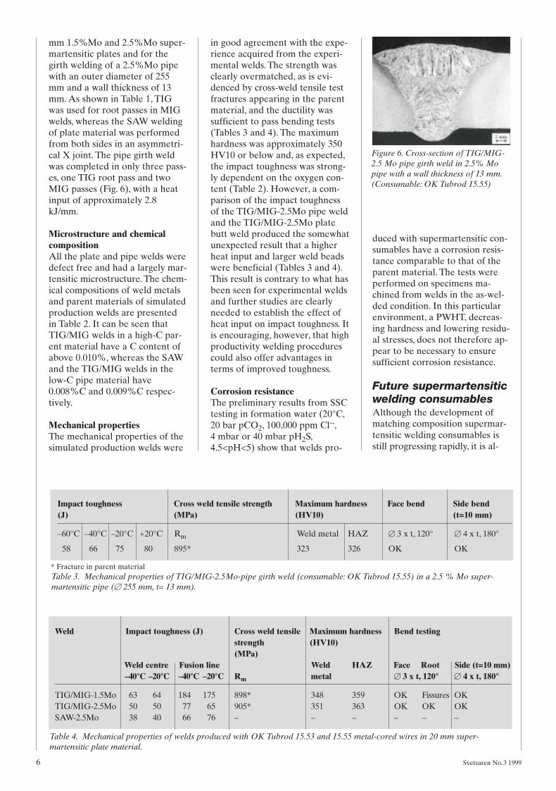
mm 1.5%Mo and 2.5%Mo super-martensitic plates and for thegirth welding of a 2.5%Mo pipewith an outer diameter of 255mm and a wall thickness of 13mm. As shown in Table 1, TIGwas used for root passes in MIGwelds, whereas the SAW weldingof plate material was performedfrom both sides in an asymmetri-cal X joint. The pipe girth weldwas completed in only three pass-es, one TIG root pass and twoMIG passes (Fig. 6), with a heatinput of approximately 2.8kJ/mm.
Microstructure and chemicalcompositionAll the plate and pipe welds weredefect free and had a largely mar-tensitic microstructure. The chem-ical compositions of weld metalsand parent materials of simulatedproduction welds are presentedin Table 2. It can be seen thatTIG/MIG welds in a high-C par-ent material have a C content ofabove 0.010%, whereas the SAWand the TIG/MIG welds in thelow-C pipe material have0.008%C and 0.009%C respec-tively.
Mechanical propertiesThe mechanical properties of thesimulated production welds were
in good agreement with the expe-rience acquired from the experi-mental welds. The strength wasclearly overmatched, as is evi-denced by cross-weld tensile testfractures appearing in the parentmaterial, and the ductility wassufficient to pass bending tests(Tables 3 and 4). The maximumhardness was approximately 350HV10 or below and, as expected,the impact toughness was strong-ly dependent on the oxygen con-tent (Table 2). However, a com-parison of the impact toughnessof the TIG/MIG-2.5Mo pipe weldand the TIG/MIG-2.5Mo platebutt weld produced the somewhatunexpected result that a higherheat input and larger weld beadswere beneficial (Tables 3 and 4).This result is contrary to what hasbeen seen for experimental weldsand further studies are clearlyneeded to establish the effect ofheat input on impact toughness. Itis encouraging, however, that highproductivity welding procedurescould also offer advantages interms of improved toughness.
Corrosion resistanceThe preliminary results from SSCtesting in formation water (20°C,20 bar pCO2, 100,000 ppm Cl–,4 mbar or 40 mbar pH2S,4.5<pH<5) show that welds pro-
duced with supermartensitic con-sumables have a corrosion resis-tance comparable to that of theparent material. The tests wereperformed on specimens ma-chined from welds in the as-wel-ded condition. In this particularenvironment, a PWHT, decreas-ing hardness and lowering residu-al stresses, does not therefore ap-pear to be necessary to ensuresufficient corrosion resistance.
Future supermartensiticwelding consumablesAlthough the development ofmatching composition supermar-tensitic welding consumables isstill progressing rapidly, it is al-
6 Svetsaren No.3 1999
Figure 6. Cross-section of TIG/MIG-2.5 Mo pipe girth weld in 2.5% Mopipe with a wall thickness of 13 mm.(Consumable: OK Tubrod 15.55)
Impact toughness Cross weld tensile strength Maximum hardness Face bend Side bend(J) (MPa) (HV10) (t=10 mm)
–60°C –40°C –20°C +20°C Rm Weld metal HAZ B 3 x t, 120° B 4 x t, 180°
58 66 75 80 895* 323 326 OK OK
* Fracture in parent material
Weld Impact toughness (J) Cross weld tensile Maximum hardness Bend testingstrength (HV10)(MPa)
Weld centre Fusion line Weld HAZ Face Root Side (t=10 mm)–40°C –20°C –40°C –20°C Rm metal B 3 x t, 120° B 4 x t, 180°
TIG/MIG-1.5Mo 63 64 184 175 898* 348 359 OK Fissures OKTIG/MIG-2.5Mo 50 50 77 65 905* 351 363 OK OK OKSAW-2.5Mo 38 40 66 76 – – – – – –
Table 3. Mechanical properties of TIG/MIG-2.5Mo-pipe girth weld (consumable: OK Tubrod 15.55) in a 2.5 % Mo super-martensitic pipe (B 255 mm, t= 13 mm).
Table 4. Mechanical properties of welds produced with OK Tubrod 15.53 and 15.55 metal-cored wires in 20 mm super-martensitic plate material.
Svetsaren 3,1999 2000-01-20 15.14 Sidan 6
ready obvious that this conceptoffers a number of advantages interms of properties, productivityand the chance to perform aPWHT when desired.One furtheradvantage that is often over-looked is the fact that a marten-sitic weld metal microstructure isexpected for all levels of dilutionwith parent material when weld-ing with a supermartensitic con-sumable. This is clearly an advan-tage compared with what hap-pens when using duplex or super-duplex consumables, as the result-ing microstructure in this case isdirectly related to the degree ofdilution.
In conclusion, although the fur-ther fine tuning of matching com-position supermartensitic con-sumables is expected, it is nowpossible to predict the micro-structure from the new supermar-tensitic weld metal constitutiondiagram and the relationship bet-ween microstructure, compositionand properties is fairly wellunderstood. It is therefore mostprobably only a matter of timebefore supermartensitic consum-ables replace duplex and super-duplex in the welding of super-martensitic stainless steel.
ConclusionsMetal-cored wires have been de-veloped for supermartensiticsteels; OK Tubrod 15.53 with1.5%Mo is suitable for steels with0–1.5%Mo and OK Tubrod 15.55with 2.5%Mo is intended forsteels with an Mo content of upto 2.5%Mo. A very low C and Ncontent (<0.01%) was consistent-ly obtained in SAW, MIG/MAGand TIG welding.
A constitution diagram wasdesigned for supermartensiticweld metals defining the compo-sitional ranges that produce amartensitic microstructure andproviding information on the solidification mode and retainedaustenite.
Weld metal strength over-matched parent material strength,apart from excessive weld metalresidual austenite content. Themaximum hardness was approxi-mately 350 HV10 or lower at0.010%C. The impact toughnesswas critically dependent on the
weld metal oxygen content andwas reduced by residual ferrite.
A short (5 min/620°C) PWHTincreased impact toughness andreduced hardness.
SSC testing shows that weldsproduced with supermartensiticconsumables have a corrosion re-sistance comparable to that of theparent material.
It is shown that supermarten-sitic consumables can be usedwith realistic fabrication weldingprocedures to produce high-qua-lity welds with mechanical andcorrosion properties that matchrequirements.
AcknowledgementsL. Coudreuse (CLI, France) isgratefully acknowledged for per-forming the corrosion testing.
References1. J. Enerhaug and P. E. Kvaale, 1996,
Qualification of welded super 13%Crmartensitic stainless steels for sourservice applications. Proc. Materiald-agen, 13 November 1996, Stavanger,Norway.
2. E. Perteneder, J. Tösch and G. Raben-steiner,1997, Zur Metallurgie derSchweissung weich martensitischer13% Cr Chromstähle für Öl- undGaspipelines, Proc. Int Conf. Weldingtechnology, materials and materialstesting, fracture mechanics and qual-ity management, September 1997,Vienna, Austria, Vol. 1, pp. 43-56.
3. A.W. Marshall and J.C.M. Farrar,1998, Welding of ferritic and marten-sitic 13%Cr steels. IIW Doc. IX-H452-99.
4. J.C.M. Farrar and A.W. Marshall,1998, Supermartensitic stainless steels– overview and weldability. IIW Doc.IX-H 423-98.
5. L. M. Smith and M. Celant, Martensit-ic stainless flowlines – Do they pay?,Proc. Supermartensitic StainlessSteels’99, May 1999, Brussels, Bel-gium, pp. 66-73.
6. J.J. Dufrane, 1998, Characterisation ofa new family of martensitic-supermar-tensitic plate material for gas trans-port and processing. Proc. Euro-corr’98, September 1998, Utrecht, theNetherlands.
7. L. Karlsson, W. Bruins, C. Gillenius, S.Rigdal and M. Goldschmitz, Matchingcomposition supermartensitic stain-less steel welding consumables. Proc.Supermartensitic Stainless Steels’99,May 1999, Brussels, Belgium, pp. 172-179.
8. L. Karlsson, W. Bruins, S. Rigdal andM. Goldschmitz, Welding supermar-tensitic stainless steels with matching composition consumables. Proc. Stain-less Steel’99 – Science and Market,June 1999, Chia Laguna, Sardinia, Ita-ly, Vol. 3, pp. 405-414.
9. J.C. Lippold, 1991, A review of thewelding metallurgy and weldability offerritic stainless steels. EWI ResearchBrief B9101.
10. M.C. Balmforth and J.C. Lippold,1998, A preliminary ferritic-martensi-tic stainless steel constitution dia-gram. Welding Journal, Vol. 77, No. 1,pp. 1s-7s.
11. R.H. Kaltenhauser, 1971, Improvingthe engineering properties of ferriticstainless steels. Metals EngineeringQuarterly, Vol 11, No. 2, pp. 41-47.
Svetsaren No.3 1999 7
About the authorsWouter Bruins is developmentengineer for the ESAB group,located in Utrecht, The Nether-lands. Currently he is involved inthe development of stainless steelcored wires for supermartensiticsteels.
Michael Goldschmitz is develop-ment engineer cored wires for theESAB group, located in Utrecht,The Netherlands. He was nomina-ted senior expert in 1995. He ispresently involved in several deve-lopment projects concerning stain-less steel.
Leif Karlsson, Ph.D, Senior Expertin welding of stainless steels at theESAB Central Laboratories inGöteborg, Sweden. He JoinedESAB in 1986 after graduatingfrom Chalmers University of Tech-nology, Göteborg with a Mastersdegree in Engineering Physics in1981 and finishing his Ph D. inMaterials Science in 1986. AtESAB he has been working withR&D on highly alloyed weldmetals devoting much time toduplex stainless weld metals.
Solveig Rigdal, M.Sc. and EWE, isworking as a development engi-neer in the department for Auto-matic Welding Consumables withinR&D in ESAB. After graduatingin chemistry from the University inGöteborg in 1974 she has beenworking with consumable develop-ment at Elga in Lerum and at AirLiquide in Malmö before joiningESAB in 1982.
Svetsaren 3,1999 2000-01-20 15.20 Sidan 7

8 Svetsaren No.3 1999
Despite low oil prices and slowworld economic growth, pipe-line construction continues at arate of 20–25 000 km per year.A large part of this arisesthrough the demand for natu-ral gas, spurred on by the needto reduce CO2 emissions —natural gas produces 50% lessthan coal and 30% less thanoil. Pipelines vary from around15 centimetres to more than ametre in diameter and in lengthup to thousands of kilometres.Individual pipes are normally12 m, or occasionally 18 m inlength so every kilometre of linerequires 83 or 56 welded joints.
While in many cases there aresimilar technical requirements forprocess pipework within the fac-tory fence and for linepipe out-side the fence, there is a funda-mental economic difference bet-ween the two. Many sections ofprocess pipework can be weldedat the same time: if a faster rateof progress is needed, more weld-ers can be deployed. Line pipelaying, on the other hand, in-volves such a large team of oper-ators and heavy equipment, notonly for welding but also fortrenching, pipe handling, NDTand so on, and such disruption ofagricultural or other activitiesalong the right of way, that eachsection of pipeline, in the West atleast, is laid progressively fromone end to the other. The pipecan only advance across the coun-try, or indeed the sea bed, as fastas the individual sections can bejoined together. Not only is weld-ing always on the critical path forpipe laying, but it is generally thesingle rate-determining process inthe activity. This puts a high pre-mium on speed and productivityin pipeline welding. Several com-panies of the ESAB Group havebeen involved in this activity formany years and can offer a rangeof options for pipe welding.
MMA weldingThe first arc-welded pipelineswere joined using cellulosic elec-trodes, which were developed in1929. The breakthrough in pro-duction speed came in 1933 withthe introduction of the “stove-pipe” technique in which the elec-trodes were used in the down-ward direction for all passes in-cluding the root. With only minorchanges, stovepipe welding is stillused today on a wide range ofpipelines. Several characteristicsof cellulosic electrodes makethem ideal for the purpose. Thecoating is very thin and requireslittle energy to melt it, so nearlyall the electrical energy of the arcis available to melt the electrodeand parent steel. Organic materi-al in the coating produces a volu-minous gas shield which protectsthe weld metal from the atmos-phere even when the arc lengthvaries, so the welder can use vari-ations in arc length to exerciselimited control over melting andpenetration, helped by a suitablepower source. Hydrogen ions inthe arc plasma increase penetra-tion. Slags are formulated to befast freezing so that high currents
can be used in the vertical-downposition without the slag runningahead and flooding the arc. Allthese features of the first E6010cellulosic electrodes are contin-ued in today’s types.
One further characteristic dis-tinguishes ESAB’s Pipeweld elec-trodes. For some 45 years, cellu-losic electrodes were formulatedto run with high arc voltages inthe belief that, as in the case ofE7018 and especially E7024types, this would lead to highermetal deposition rates. When putto the test in 1978, however, thisidea proved to be false. Bothcommercial products and elec-trodes specially formulated to runat high and low arc voltages allshowed the same core burn-offrate at a given current. Unlikeelectrodes which produce a “cup”of flux at the tip within which theheat of the arc is retained, any ex-tra arc voltage in the case of cel-lulosic electrodes simply results inmore radiant heat being lost fromthe arc column. This is not to saythat all cellulosic electrodes de-posit metal at the same rate, butit is found that the real differenc-es which exist arise from varying
Linepipe welding beyond 2000by D.J.Widgery, ESAB, Waltham Cross, U.K.
Svetsaren 3,1999 2000-01-20 15.21 Sidan 8
Svetsaren No.3 1999 9
spatter losses rather than fromvarying burn-off rates. This isgood news for the welder, whosince the introduction of thePipeweld series in 1979 no longerhas to put up with a harsh arc inthe belief that this is the fastestway to weld pipe: a smoother, lessspattery arc is not only morecomfortable but offers productiv-ity advantages as well. For root-ing, the old-established E6011type, NuFive, achieves a similarresult with a mixed sodium andpotassium binder.
Welding engineers unfamiliarwith traditional stovepipe weldingare often alarmed to discover thatthe cellulosic electrodes give weldhydrogen contents typically in ex-cess of 50 ml/100g. This has notprevented them from being usedwithout problems on steels up toAPI 5LX 70, since the proceduresdeveloped, especially the use of ahot pass following immediately after the root pass to temper thebead and HAZ, were designed todeal with that situation. However,for higher strength steels, or wherehydrogen cracking is thought topose an unusual risk, such as inhot tapping operations, basic elec-trodes designed to operate in thedownward direction have been de-veloped. The best known of theseis Filarc 27P, which allows a signifi-cant improvement in pipe weldingproductivity as compared withconventional E7016 or 7018 elec-trodes and has an establishedrecord over 20 years of pipe weld-ing. This has now been joined bythe higher strength 37P, which issuitable for pipe grades up to X80.
Semi-automatic andmechanised weldingThe development of CO2-shiel-ded welding in the USSR in the1950s opened the way for semi-automatic pipeline welding andthe first CO2-welded cross-coun-try pipeline in the USA was laidin 1961. Two years later, a compa-ny which became part of theESAB Group was involved in thefirst UK pipelines to be weldedwith the CO2 process, the SouthWales Supergrid and the PennineSpur. By 1966 the process hadbeen greatly refined for theNorth Wales Supergrid and later
for other pipelines to distributethe newly discovered natural gasfrom the North Sea.
Although thousands of kilome-tres of pipeline were laid semi-automatically using CO2 with sol-id wire, the possibility of increas-ing speeds still further led to ef-forts to mechanise or automatethe gas-shielded process. Severalof these were successful and to-day this is the preferred methodfor offshore and long-distance on-shore pipelines.
Mechanised pipe welding sys-tems now all use on-site end bev-elling to guarantee the good fit-up that is needed to make highproduction speeds possible. Twobroad categories of rooting sys-tem are available. CRC use aninternal welding bug, while sever-al other companies use copperbacking rings of ingenious design,with all welding from the outside.Many thousands of kilometres ofpipe have been successfully laidwith both systems. For mainlinewelds, welding is in the downwarddirection for root, filling and cap-ping passes. Welding parametersare increasingly under computercontrol, so modern pipe weldingsystems can legitimately be de-scribed as automatic.
In the early days of mechan-ised pipe welding, 0.9 mm (0.035in) Oxweld 65 triple-deoxidisedwire was widely used and thesame wire, now known as Spoo-larc 65, is still supplied by theESAB Group. A more recent de-velopment, Spoolarc XTi, is avail-able where improved toughness isrequired.
Tubular wireWhile the advantages of tubularwire have led to its widespreadadoption in many other sectors,pipe welding has always been aconservative industry and hasbeen relatively slow to move totubular wires. That situationseems to be about to change.
One reason why semi-automa-tic pipe welding with solid wiresdid not replace MMA pipe weld-ing to any great extent was users’fear of lack-of-fusion defects. Atthe same time, the main reasonwhy tubular wires have succeededwhile solid wires have failed in
other industries such as ship-building is their lower susceptibil-ity to lack of fusion.
For semi-automatic pipe weld-ing, modern all-positional rutileflux-cored wires such as OK Tub-rod 15.17 offer a low-hydrogen,high productivity alternative tocellulosic electrodes. Because ru-tile wires combine a very control-lable spray transfer at all currentswith a slag stiff enough and volu-minous enough to support theweld metal in welding verticallyupwards, there is less to gain bywelding downwards than there iswith MMA electrodes and mostprocedures are for upward weld-ing. Rutile wires have found aparticular place in carrying outrepairs and tie-ins, where mech-anised welding is not always fea-sible or where ultimate speed isless important than it is in mainline welding. In the early days ofCO2-shielded pipe welding, lossof shielding when the wind blewcould be a source of weld poros-ity. Today, the tents in whichwelding is performed are so wellsealed that on one recent linethere were reports of welders suf-fering from lack of oxygen as thetent filled up with shielding gas,so the use of argon mixtures oflower density than CO2 is pos-sible without risking loss ofshielding.
The relatively high speed withwhich it was possible to weldopen pipe roots with solid wireunder CO2 can also be achievedwith modern metal-cored wires ofthe type designed for CO2 opera-tion, such as OK Tubrod 14.12,while the risk of defects is re-duced at the same time. If onelesson has been learnt by thewhole pipe welding industry sincethe 1960s, though, it is the advan-tage of using on-site end prepara-tion and efficient clamping to en-sure reproducible joint geometryeven when fully automatic weld-ing is not used. Only in this waycan open roots be welded at opti-mum speed.
Metal-cored tubular wires beennot been regarded as a viable re-placement for solid wires inmechanised pipe welding untilvery recently, though their use isnow starting to be seen as logical.
Svetsaren 3,1999 2000-01-20 15.22 Sidan 9

10 Svetsaren No.3 1999
A 1.2 mm metal-cored wire istypically used in place of a 1.0mm solid wire as the tubular typeis of lower density. Productivity isimproved by up to 20% and it ishoped that as statistical evidenceis gathered, it will be possible toreduce the defect incidence belowthe 5–6% regarded as acceptablefor solid wires.
For parts of the world whereshielding gas is not readily avail-able, self-shielded tubular wiresfor pipe welding have been avail-able for more than 20 years. The-se are magnificent examples ofthe consumable developer’s art,and it is difficult not to be im-pressed by the ingenuity whichgoes into their design. Unfortu-nately, compromises have to bemade in formulating self-shieldedwires and productivity tends tosuffer as compared with gas-shiel-ded types. As a result, the numberof lines laid with self-shieldedwire remains small, though thatcould change as the proposedpipelines across Central Asiastart to be built.
Double jointingThe rate of progress of a pipelineacross country is equal to the rateof butt welding multiplied by thelength of a pipe section. Where itis possible to double the length ofthe sections by welding them off-line, or “double jointing”, thespeed of the line is similarly dou-bled. The feasibility of doublejointing depends on access to thesite: if the right of way is straightand wide, even triple jointing maybe possible in some cases. Doubleor triple jointing is now commonon laybarges laying offshore pipe-lines.
The advantage for the weldingengineer of welding off-line is thatthe pipe can be rotated so thatwelding is all downhand, thus al-lowing the very productive sub-merged arc process to be used. Formany years, the standard consum-ables for the job were OK Autrod12.34 with OK 10.71 flux, whichare suitable for pipe steels up toX70 grade. A more recent devel-opment is the use of tubular wiresfor the submerged arc process.
Where double jointing is car-ried out on a lay barge, the pro-
cess may be strictly off-line, but itis still required to keep up withthe fixed position welding. In thatcase, the conventional use of asingle 3 or 4 mm diameter solidwire may not be fast enough. Theuse of twin 2.4 mm solid wirescan speed up the process, but tu-bular wire also brings benefits ofup to 30% in productivity com-pared with solid wire and it toolends itself to twin arc welding.OK Tubrod 15.24, a 1% Ni wire,gives excellent results for doublejointing and is again used withOK 10.71 flux.
Welding high strengthpipe steelsPipe steels with yield strength upto 480 MPa (X70) are now incommon use and a full range ofMMA electrodes, solid and tubu-lar wires is available to weldthem. The first X80 pipelines witha minimum yield strength of 550MPa have been laid on land andinvestigations are under way tolook at the practicality of off-shore lines in X80 steel.
One of the questions whichhas to be answered about weld-ing high strength steels in gener-al and pipe steels in particular iswhether the weld metal isshould overmatch the parentsteel. Most pipe welding stan-dards such as API 1104 requirethe weld metal to match thespecified minimum tensilestrength of the pipe but specifi-cally exclude any need to matchthe actual pipe strength. Giventhat in service the major stressacts on the longitudinal weld,this may seem reasonable and itis the basis on which land lineshave so far been laid. At theX80 strength level, it is generallyconcluded that cellulosic elec-trodes will only be used for theroot and perhaps the hot pass,since it may be difficult to achie-ve the required toughness andresistance to hydrogen crackingusing them in the fill and cappasses. In the root, a degree ofundermatching is usually per-missible, even to the extent ofusing the E6011 NuFive elec-trode, provided the bulk of thejoint is filled with weld metal of
matching strength. For the fillingand capping passes, the E9018-Gelectrode Filarc 37P is used inthe vertical-down direction.Alternatively, a rutile flux-coredwire such as OK Tubrod 15.19, astronger version of 15.17, maybe used in the upward direction.
In mechanised vertical-downwelding, where a narrow jointpreparation is combined with ahigh travel speed so that weldcooling rates are extremely high,even carbon-manganese consum-ables such as Spoolarc XTi canproduce weld metals strong andtough enough to match mostspecifications for welding X80pipe.
For offshore lines in X80 pipe,some contractors may look forweld metals which overmatch theactual rather than the nominalpipe strength in order to take ad-vantage of new ways of calculat-ing allowable defect size. Metal-cored wires such as Tubrod 14.05and 14.06 not only allow realovermatching of X80 pipe, but of-fer a significant productivity ad-vantage at the same time. For thefuture, constant development ofnew electrodes and wires in ESAB’s laboratories will allowany foreseeable grades of pipe-line steel to be successfully welded.
About the authorDavid Widgery is Group SpecialProjects Manager based in Walt-ham Cross, England. After gradua-tion he joined The Welding Insti-tute, Cambridge in 1964, gaining aPh D from Cambridge Universityfor work on weld metal toughnessin 1975. In 1976 he was awardedthe American Welding Society’sJames F. Lincoln Gold medal andjoined GKN Lincoln Electric asTechnical Manager. There he wasresponsible for the development ofall types of welding consumablesand equipment. Following ESAB’sacquisition of GKN Welding in1982 and BOC Welding in 1983, hemoved to Waltham Cross as Devel-opment manager, Flux-CoredWire. In 1996 he took on a newrôle co-ordinating developmentprojects within the Group.
Svetsaren 3,1999 2000-01-20 15.23 Sidan 10

Svetsaren No.3 1999 11
Tanko S.P.A. (Syracuse,Italy) is a firm specialis-ing in the manufactureof tanks which are readyfor use for the storage ofoil and gas products.The product range com-prises both traditionaltanks and cryogenicones for low-temperatu-re application (LNG).
Double-head tanksTanko has acquired a great dealof experience of manufacturingvessels for LING transportationby sea. In this application, thefirst three in a series of double-head tanks (intersecting vessels)have been already delivered toFincantieri to be used for LPG(NH3) at a temperature of –48° Cand a pressure of 5 bar. At pre-sent, Tanko is finishing the secondset of double-head tanks for thesame customer.
In all, the estimated workingtime totals 300,000 man-hours.
The base material in these ves-sels was 13 Mn Ni 63 (EN10028/4), a fine-grain steel, andthey were assembled, tested andinsulated at the Punta Cungoyard (Syracuse, Sicily).
After being completed, thetanks were transported on largebarges to Genoa harbour where aproper portal crane had beenconstructed to lift and load thevessels onto the ship.
Each double tank was 32 me-tres long, 21 metres wide and 12metres high, with a weight of 700tonnes.
Due to the dimensions, the ves-sel was not fully constructed in-doors, but a yard was set up whe-re the three sub-assembled com-ponents were joined together tocreate a single tank.
For a single double vessel,more than 150 plates were used,longitudinally and circumferen-tially welded to one another and to the central partition plate.
The heads, four for each tank,consisted of sixteen sectors andone spherical plate, all of themcold formed.
Suitable working procedureswere used to keep the final toler-ances within 0.1%.
WeldingIn addition to the cold forming ofthe head components, the work-ing procedure included plate cut-ting, bevelling, bending and weld-ing.
The head sectors were weldedusing the SAW process, whileSAW and FCAW processes wereused for most of the total welds,where stick electrodes were usedon quite a small scale.
All the vertical joints werewelded with Filarc PZ 6125,0.9% basic flux-cored wire andall the circumferential jointswere welded with sub-arc con-sumables and a circomatic weld-ing machine.
Inspection and rulesThe tanks were designed andmanufactured to comply with themost rigorous national and inter-national rules.
All the outer shell welds andall the butt joints were checked100% by RX, while a 100% UTinspection was carried out on thepartition plate joint to the mainshell.
The entire project complieswith EN ISO 9001.
Tanko know-how in double-head tanks
by Ben Altemühl, Filarc Welding Industries, The Netherlands
The welding consumables supplied by ESAB Italy were:
SAW: Siderfil Ni 26 (Siderotermica Brand) + OK Flux 10.62
FCAW : Filarc PZ 6125SMAW: Filarc 75
Svetsaren 3,1999 2000-01-20 15.23 Sidan 11

International standar-disation is organised bythe ISO and IEC. TheISO is responsible formost standardisation.The IEC is responsiblefor electrotechnical stan-dardisation.
European standardisation is or-ganised by the CEN, CENELECand ETSI. The CEN is respon-sible for most standardisation.
The CENELEC is responsible forelectrotechnical standardisation,apart from telecommunications,for which the ETSI is responsible.
International welding standar-disation within the ISO began in1947 when ISO/TC44 Weldingwas set up. European weldingstandardisation began in 1987when CEN/TC121 Welding wascreated. The CEN had been inoperation since 1960, but it be-came far more active when theEU decided on a new method inthe mid-1980s. As a result, the de-
tailed technical rules were nolonger included in directives butin harmonised standards.
ISO/TC44 Welding andallied processesThe set-up is shown in Figure 1.The chairman is Jean-PierreGourmelon of France. The secre-tary is Hélène Brun-Maguet,AFNOR, France.
In the “Vienna Agreement”,the ISO and CEN have agreedto co-operate in order to avoidthe duplication of work. When itcomes to welding, about 70% ofthe standards are the same forthe ISO and CEN. Some of thestandards are prepared withinISO/TC44, while CEN/TC121 isresponsible for the remainder.
SC3 Welding consumables wasreorganised in 1994. SC3 has sin-ce published ISO14175 (EN439)Shielding gases for arc weldingand cutting.
The International Institute ofWelding, IIW, has been acceptedby the ISO as an internationalstandardising body. IIW Com-mission II Arc Welding is devel-oping some standards for weld-ing consumables.
There are two different sys-tems for the classification ofwelding consumables—one inEurope, the other in the “PacificRim” countries. The existence ofthese two systems has made itimpossible to prepare standardsfor the classification of weldingconsumables that can be accept-ed on a worldwide basis. The so-lution that is now being tested isto prepare “cohabitation stan-dards”. In these standards, thereare two routes, if necessary, oneEuropean, the other “Pacific
12 Svetsaren No.3 1999
Welding engineering standardisation—
international and Europeanby Olof Dellby, Svetskommissionen, Sweden and Ulf P Karlsson, ESAB, Laxå, Sweden
Welding of heat exchanger.
Svetsaren 3,1999 2000-01-20 15.26 Sidan 12
Rim”. The first cohabitationdraft will be sent out for DISvoting at the beginning of 2000.
SC4 Arc Welding Equipment,see IEC/TC26.
SC6 Resistance welding hasprepared a large number ofstandards and work to revisethem has just started. Nearly allof them have become Europeanstandards.
SC7 Representation andterms has prepared standards in-cluding ISO2553 welded, brazedand soldered joints—symbolicrepresentation on drawings. Thisstandard is due for revision. The-re are two systems for weldingdesignations, ISO2553 and theUS AWS. The existence of twosystems means that there is arisk of mistakes. Most of theSC7 standards have been accept-ed by CEN/R121.
SC8 Gas welding equipmenthas prepared a large number ofstandards. Unfortunately,CEN/TC121/SC7 Gas weldingequipment has not accepted theISO standards but has preparedits own standards which deviateto some extent from the ISOstandards.
SC10 Unification of require-ment in the field of welding hasprepared standards includingISO5817 Arc welded joints insteel—fusion welding—guidanceon quality levels for imperfec-tions. This standard is currentlybeing revised. Some SC10 stan-dards have been accepted byCEN/TC121. Otherwise, SC10accepts European standads.
SC5 Testing and inspection ofwelds,
SC9 Health and safety andSC11 approval requirements
for welding and allied processespersonnel run small operationsof their own. The sub-commit-tees accept European standards.
IEC/TC26 Electric WeldingInternational standards for weld-ing equipment are handled byIEC TC26. The committee has aGerman secretariat, with Dr. KarlBöhme as its secretary, and aSwedish chairman, Ulf P Karls-son. Within ISO/TC44, there is asubcommittee, SC4, entitled “Arc
Svetsaren No.3 1999 13
ISO/TC44Welding and allied
processes
Soldering and brazingmaterials
Arc welding equipment
Testing and inspection ofwelds
Resistance welding
Representation andterms
Gas welding equipment
Health and safety
Unification ofrequirements in the fieldof metal welding
Approval requirementsfor welding and alliedprocesses personnels
SC12
SC11
SC10
SC9
SC8
SC7
SC6
SC5
SC4
Welding consumables
SC3
Health and safety inwelding and alliedprocesses
Specification and qualifica-tion of welding proceduresfor metallic materials
Destructive tests onwelds
Approval requirementsfor welding and alliedprocesses personnel
Welding consumables
Quality management inthe field of welding
Non-destructiveexamination
Representation andterms
Gas welding equipment,cutting and alliedprocesses
Brazing and soldering
SC9
SC8
SC7
SC6
SC5B
SC4
SC3
SC2
SC1
WG
13
CEN/T C 121Welding
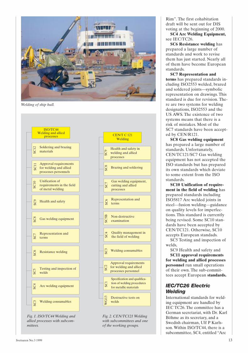
Fig. 1. ISO/TC44 Welding andallied processes with subcom-mittees.
Fig. 2. CEN/TC121 Weldingwith subcommittees and oneof the working groups.
Welding of ship hull.
Svetsaren 3,1999 2000-01-20 15.27 Sidan 13

welding equipment”. At the pre-sent time, there is no rivalry bet-ween the two groups. To reachglobally accepted standards, thetwo organisations have joinedforces and set up a joint workinggroup (JWG1) with the chairmanof IEC/TC26 as the convener.The aim of IEC/TC26 togetherwith ISO/TC44/SC4 is to producea series of standards coveringwelding equipment and accesso-ries of all kinds.
Table 1 shows the present situ-ation in terms of published stan-dards and standards under prep-aration:
CEN/TC121 WeldingThe set-up is shown in Figure 1.The chairman since the start in1987 has been Birger Hansen,Denmark. The secretary is LoneSkjerning, DS, Denmark.
TC121 prepares general stan-dards for welding. TC121 hopesthat the CEN TCs preparingproduct standards will make ref-erence to the TC121 standards in-
stead of making their own rulesfor welding. TC121 has no powerto force the product standardscommittees to use TC121 stan-dards. This is the weak point inthe CEN system. There is no cen-tral authority in the CEN respon-sible for co-ordinating the rules indifferent standards.
WG13 Destructive tests onwelds has published standards fordestructive testing, bend testingand tensile testing of welded joints.
SC1 Specification and qualifi-cation of welding procedures formetallic materials has publishedeight standards in the EN288 se-ries. These standards are nowunder revision and the prENs willbe sent out in the beginning ofyear 2000. SC1 has also pub-lished a technical report on mate-rials classification for welding.SC1 is preparing an extension ofthe EN288 series with a newnumbering system, see Figure 3.
SC2 Approval requirements forwelding and allied processes per-sonnel has published EN287-1
Welder approval—Steel, EN287-2Welder approval—Aluminiumand EN719 Welding co-ordina-tion. Standards for copper andnickel has also be published.EN287-1 is under revision, prENis expected in 2000.
SC3 Welding consumablesSC3 has published 19 standards.Most of them are classificationstandards for consumables of var-ious types. SC3 has also pub-lished some standards on the test-ing of consumables. SC3 has pre-pared a standard on type approv-al that is now under considera-tion. This standard and a standardwith supplementary tests are in-tended to be used in a Europeansystem for the type approval ofconsumables. In addition to thestandards, the CEN membersmust agree on a voluntary systemfor the reciprocal approval ofconsumable testing, i e consum-ables approved in one CEN coun-try are approved in all other CENcountries.
14 Svetsaren No.3 1999
Number Title Status Date Personal comment
IEC 60974-1 Arc welding equipment. Published 1989 Unfortunately, it has not yet Part 1 Power sources Revised 1998 been published as an ISO standard
IEC 60974-1, A1 AmendmentPlasma power sources FDIS January 2000 Published 2000 at the earliest
IEC 60974-2 Liquid cooling systems CD December 1999 Published 2002 at the earliest
IEC 60974-3 Arc starting and stabilising devices WG doc CD in March 2000
IEC 60974-4 Pulsed power sources Already implemented in 60974-1
IEC 60974-5 Wire feeders CDV January 2000 Published 2001 at the earliest
IEC 60974-6 Power sources for manual welding with Currently it exists as a European limited duty WG doc March 2000 standard EN 50060
IEC 60974-7 Torches. FDIS September 1999 Published 2000 at the earliest
IEC 60974-8 Plasma cutting systems Becomes part of 60974–1, throughAmendment 1 and part of –7, Torches.
IEC 60974-9 Graphical symbols for Requires approvalarc welding NWI of IEC TC3
IEC 60974-10 EMC requirements CDV January 2000 Currently exists as a European standard EN 50199.
IEC 60974-11 Electrode holders Published 1992 For revision 2002
IEC 60974-12 Coupling devices for welding cables Published 1992 For revision 2002
IEC 60974-13 Terms for arc welding Requires approval equipment PWI of IEC TC3
Table 1. IEC/TC336 Electric welding.
Svetsaren 3,1999 2000-01-20 15.28 Sidan 14

SC4 Quality managementin the field of weldingSC4 has a large scope. It is a “miniTC121”. The most important stan-dard SC4 has published is theEN729 series, EN729—Quality re-quirements for welding—Fusionwelding of metallic materials. The-se standards are “umbrella” stan-dards for welding. They providegood support for a company usingwelding in its production to en-sure that the welding is done in acompetent manner. The use ofthese standards will considerablyreduce the problems and enhancethe quality.
The EN729 series is intendedfor arc welding. For resistancewelding, SC4 has prepared prENISO14554, which will be publishedin 2000.
Another important group ofstandards is the EN1011 series.EN1011-1 General Guidance forarc welding has been published.
EN1011-2 Ferritic steels has re-cently been sent out for a secondround of consideration in the nearfuture. It has not been possible toagree on one system for deter-mining the preheating tempera-ture. The standard has two sys-tems, one British, which is a mod-ernised BS513, and a German sys-tem. They give different values. Aworking group is discussing vari-ous systems for determining thepreheating temperature.
EN1011-3 Stainless steels andEN1011-4 Aluminium will bepublished in 2000.
SC9 Health and safetySC9 prepares standards for healthand safety in welding that are notprepared by other CEN commit-tees. SC9 has prepared standardsfor sampling airborne particlesand gases in the operator’sbreathing zone and laboratorymethods for particles and so on.
Other CEN committees arepreparing standards related tohealth and safety in welding andallied processes. SC9 follows thiswork.
CEN/TC240 ThermalsprayingCEN/TC240 has published sixstandards.
TC240 is preparing a series ofstandards for quality require-ments, prEN ISO 14922-1/4,which will be published in 1999.
CENELEC TC26European standards for weldingequipment are handled byCENELEC TC26. The commit-tee has a German secretariat,with Dr. Karl Böhme as secre-tary, and a British chairman,Geoffrey B Melton, TWI. As theEuropean members of IEC TC26are the same as the members ofCENELEC TC26, there is nor-mally only some administrativework involved in transferring anIEC document to a CENELECdocument and obtaining a Euro-pean standard at the same timeas the international one by par-allel voting.
In 1992, the industry becameaware of the need for an EMCproduct standard for weldingequipment. A joint working groupwas set up between CISPR/B,IEC TC77, CENELEC TC210and CENELEC TC26. SecretaryGeoffrey B Melton, TWI, andconvener Ulf P Karlsson, ESAB.In December 1995, the productstandard EN 50199 Electromag-netic compatibility (EMC), Prod-uct standard for arc weldingequipment, was published.
An international EMC stan-dard has reached the CDV stage.
SC4, see under IEC TC26 Elec-tric welding
European standards forwelded productsThere are standards for simplepressure vessels, EN286. There isalso ENV 1090-1 Execution ofsteel structures—Part 1: Generalrules and rules for buildings.prEN 13445-1/7 Unfired pressurevessels and prEN 13480-1/7 Me-tallic industrial piping are beingconsidered. To some extent, thefirst one has its own rules forwelding and refers only partly toTC121 standards. The second re-fers to TC121 standards but withsome changes. As the TC121 stan-dards are general, it may happenthat a product committee wishesto reduce or step up the require-ments in a TC121 standard. Thisis naturally acceptable, but it is
not acceptable if the productcommittees write their own weld-ing rules.
ConclusionThere have been some fairly in-tensive discussions between theCEN, ISO and IIW. The author isof the opinion that the differentroles of the organisations are nowunderstood and co-operation isgood.
In CEN, there is some uncer-tainty due to the fact that theproduct committees are not obli-ged to adopt the TC121 standardsand can draw up their own rulesfor welding.
AcronymsISO International Organisation for Stan-dardisation
IEC International Electrotechnical Com-mission
CEN European Committee for Standar-disation
CENELEC European Committee forElectrotechnical Standardisation
ETSI European Committee for Electro-technical Standardisation
CD Committee draft
CDV Committee draft for voting
DIS Draft international standard
FDIS Final draft international standard
PrEN Proposal for European standard
NWI New Work Item
PWI Preliminary Work Item
WG doc. Work Group Document
Svetsaren No.3 1999 15
About the authorsOlof Dellby is secretary of theSwedish Welding Commission sin-ce 1975. His main responsibility isstandardisation. He is also activein IIW, ISO and CEN and secreta-ry of CEN/TC 121/SC 3 Weldingconsumables and ISO/TC 44/SC 3Welding consumables.
Ulf P. Karlsson is an electrotechni-cal engineer at the R&D Depart-ment at ESAB Welding Equip-ment in Laxå, Sweden. He is activein standardisation work as chair-man of SEK TK26, Arc Weldingand internationally as chairman ofIEC TC 26 Arc Welding Equip-ment. SEK = Swedish Electrotech-nical Commission.
Svetsaren 3,1999 2000-01-20 15.28 Sidan 15

The Stainless Steel World ’99Conference and Expo was held16th to 18th November in theHague, The Netherlands. Papersfrom major end users and suppli-ers were presented and ESABcontributed with 3 papers.
In parallel with the conference,an exhibition was organised whe-re a large variety of products as-sociated with stainless steels weredisplayed. ESAB had an interest-ing stand at which ESAB’s strengthin important sectors such as pulp& paper, chemical tankers andcryogenic applications wereshown.
A lot of products were on dis-play such as covered electrodes inVacPac, flux cored wires andSAW wires and flux, MIG andTIG wires and ESW/SAW stripsand fluxes for cladding. The orbi-tal TIG welding equipmentMechtig 160 and the PRB weld-ing head for tube-to-tube weldingalso attracted great interest.
The conference attracted 250delegates from key industries andanother 3.000 people visited theexhibition.
ESAB is now introducing Eco-Mig, a non-copper-coated weldingwire which improves productivityand helps to make the environ-ment cleaner.
A special production techniqueand the absence of copper coat-ing give the EcoMig wires uniquecharacteristics. They withstandhigh currents and produces a verystable arc with good penetrationand flow. This results in higherdeposition and improves produc-tivity compared with convention-al wire. As there is no coppercoating, there are no stoppagesresulting from copper flakeswhich block the wire feed conduitand contact tips. Our special pro-duction technique helps to ensurereliable feed and good currenttransfer in the contact tip.
As far as the welder is con-cerned, EcoMig improves boththe working environment andwelding. The stable arc producesless spatter. The joints are uni-form and strong. The need forfinishing work with its grindingdust and distracting noise is re-
duced. The risk of cracking as aresult of copper residue in theweld metal is eliminated. Thewelding fumes are less of ahealth hazard as the copper con-tent is lower.
ESAB’s EcoMig wire comes intwo grades—OK Autrod 12.50 forsteel with a minimum tensilestress of up to 420 MPa and OKAutrod 12.63 for steel with a min-imum tensile stress of up to 460MPa. EcoMig is supplied in envi-ronmentally-sound wire-basketreels or in the Marathon Pac bulkpackage.
The octagonal Marathon Pacdrum is made of environmentally-compatible corrugated boardwith an integrated moisture barri-er. When the drum is empty, itcan be easily compressed to pro-duce a flat package, which canthen be sorted for recycling. Thewire-basket reels can also becompacted and recycled. WhenEcoMig is introduced into theproduction process, the environ-ment experiences an overall im-provement.
16 Svetsaren No.3 1999
Stub-ends&Spatter
Nothing but benefits from EcoMig
Stainless SteelWorld ’99
Svetsaren 3,1999 2000-01-21 08.59 Sidan 16

The numerical control is the heartof any cutting process. The newNCE 620 is fast, precise, and loa-ded with the entire range of pro-
cess data. It controls all processparameters for any cutting pro-cess. After material type, thick-ness, process and desired cut qua-lity has been selected the NCE620 automatically sets ideal cut-ting speed, delay times, gas pres-sures, gas mixtures and other vari-ables. The cutting database inclu-des process data for laser, plasma.oxy-fuel and water-jet cutting.
The NCE 620 utlizes themodern high-speed processor toimplement intelligent motion con-trol algorithms. This technologyallows high dynamic accuracy,improved acceleration-decelera-
Svetsaren No.3 1999 17
ESAB MobileMaster wire fee-ders are built for harsh environ-ment such as construction sites,pipelines, shipyard, off-shore,general fabrication and mobilewelding rigs. The totally enclosed,impact-resistant case protectswelding wire from dirt, metal grit,moisture and other contaminantsand the unique “rain gutter” doordesign keeps water from dripping
Tough environment—easy choice
Intelligent process control—NCE 620
ESAB plasma makes the cutWhere do you go when you’refaced with the task of dismantlinga radioactive laboratory? Thepeople at Oak Ridge Laborato-ries contacted Manufacturing Sci-ences Corporation, which in turnstudied the available processesand equipment manufacturersand determined that ESAB Plas-marc™ equipment was a cut abo-ve the rest. Through in-depth timestudies and a review of the manydifferent types of cuts required,MSC determined that the ESABE SP-200 plasma system was thesmart choice. The versatility of theESP-200 is apparent in the re-quirements of both manual andmechanized cutting. Either manu-al cutting with the PT-26 torch or
mechanized cutting with the PT-19XLS torch mounted on fixtures,the ESP-200 provides the cuttingspeeds required to fulfill the paceof this multi-year project. Majorfixturing was required to maketwo simultaneous cuts down thelength of low level radioactivepipes. The pipes range in size from2 inches (5 cm) to 3 feet (100 cm)diameter and up to 3/4 inch (19mm) thickness. Other areas re-quire hand cutting with the PT-26torch and still others require con-tour cutting with X–Y coordinatedrive shape cutting table. All cutswith the sixteen ESP-200 systemsare made with air in the manualor mechanized mode allowingcomplete commonality of repair
tion, and faster response to dyna-mic loading while optimising ser-vo control command signals.
The high-speed processorallows new levels of motion con-trol accuracy, resulting in higherquality parts at lower total cost.This high precision motion con-trol can increase the life of thecutting equipment by reducingwear on servos and gearboxes.
The NCE 620 can be connectedto hosts, network, the Internet andIntranet, thus improving commu-nication with production planningand process control systems.
part throughout. In addition tothe sixteen ESP-200 systems, oneESP-100 system with the PT-20AM torch was put into serviceto cut thinner product as re-quired. This system also uses airas the plasma gas.
Operators making the cuts withthis equipment are required towear full protective suits and arelimited to the time they can spendin the cutting chambers. Due tothe very harsh environment whe-re these units are operating, MSCchose ESAB Plasmarc™ systemsbecause of their proven reliabilityand ability to make the cut at therequired speed and cut quality.
into wire compartment. Frontcontrols are located on a recessedpanel to protect dials and swit-ches. The rear handle makesMobileMaster easy to manoeuvreinto tight spots and the weight isonly 12 kg. The built-in torch hol-der has composite insulator
MobileMaster wire feedersoperate with reverse polarity(wire DC+) or straight polarity
(wire DC-). Wire spools with 21to 31 cm diameter and 20 kgweight for wires 0.6 mm–2.00 mmdiameter can be used.
Safety features for these wirefeeders include insulated case,low voltage torch trigger circuitand overload protection and it isdesigned to meet the most rigidstandards including IEC-974-1specification.
Svetsaren 3,1999 2000-01-21 09.02 Sidan 17
ESAB Welding & Cutting Prod-ucts, USA recently introduced the350mpi, an inverter-based weld-ing power source designed forMIG, DC TIG, carbon-arc goug-ing and stick welding.
The ESAB 350mpi operatesfrom a 230/460 volt primary,either single- or three-phase. Theunit is designed to be self-protec-ting. In the event that the ESAB350mpi is accidentally attached toa higher primary voltage, thepower supply will not be dam-aged.
The ESAB 350mpi is rated350 amps at a 60 percent dutycycle with three-phase input and225 amps at a 60 percent dutycycle with single-phase primarypower.
A five-position switch allowsoperators to set the unit for MIG,TIG, CV hot, touch TIG or stickwelding. No external control orpendant box is needed for any ofthese processes. The ESAB350mpi is compatible with all US-produced ESAB MIG wire feed-ers including: 28A, 35, 2E, 4HDand the 5XL Mongoose.
The controls are easy to usewhen MIG welding. There is aneight-position selector knob thatan operator sets for the weldingmaterial: stainless, aluminum,steel with CO2, steel with argon-based gas shielding, flux-coredwire or metal cored wire. Thelogic of the machine will selectthe correct slope and induc-tance, and give the operator ausable range of arc trim/forcesuitable for the material beingwelded.
For TIG welding, operatorshave two options, TIG or touchTIG. The TIG position consists ofa normal DC scratch-start. Whilein the touch TIG mode, the ma-chine senses contact between theelectrode and the base metal, soit can produce a ramp-up of cur-rent as the operator lifts the torchoff the base metal.
To stick weld with the ESAB350mpi, an operator selects thestick position on the five-positionswitch. Automatically, the ma-chine output changes to constantcurrent, and the output is hot.
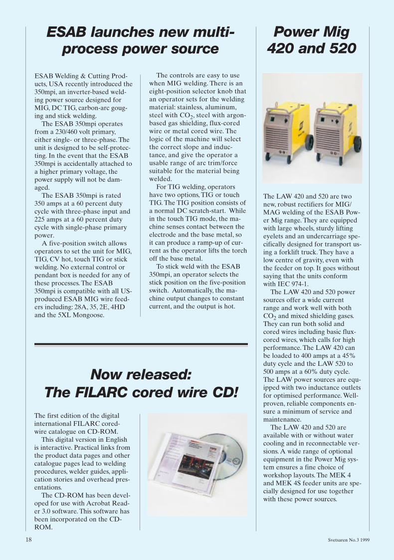
The LAW 420 and 520 are twonew, robust rectifiers for MIG/MAG welding of the ESAB Pow-er Mig range. They are equippedwith large wheels, sturdy liftingeyelets and an undercarriage spe-cifically designed for transport us-ing a forklift truck. They have alow centre of gravity, even withthe feeder on top. It goes withoutsaying that the units conformwith IEC 974-1.
The LAW 420 and 520 powersources offer a wide currentrange and work well with bothCO2 and mixed shielding gases.They can run both solid andcored wires including basic flux-cored wires, which calls for highperformance. The LAW 420 canbe loaded to 400 amps at a 45%duty cycle and the LAW 520 to500 amps at a 60% duty cycle.The LAW power sources are equ-ipped with two inductance outletsfor optimised performance. Well-proven, reliable components en-sure a minimum of service andmaintenance.
The LAW 420 and 520 areavailable with or without watercooling and in reconnectable ver-sions. A wide range of optionalequipment in the Power Mig sys-tem ensures a fine choice ofworkshop layouts. The MEK 4and MEK 4S feeder units are spe-cially designed for use togetherwith these power sources.
18 Svetsaren No.3 1999
ESAB launches new multi-process power source
Now released: The FILARC cored wire CD!
The first edition of the digitalinternational FILARC cored-wire catalogue on CD-ROM.
This digital version in Englishis interactive. Practical links fromthe product data pages and othercatalogue pages lead to weldingprocedures, welder guides, appli-cation stories and overhead pres-entations.
The CD-ROM has been devel-oped for use with Acrobat Read-er 3.0 software. This software hasbeen incorporated on the CD-ROM.
Power Mig420 and 520
Svetsaren 3,1999 2000-01-21 09.03 Sidan 18

EcoPac is a box-free bulk packag-ing intended for high volume us-ers of flux-and metal cored wires.Since there are no boxes to bediscarded, it simplifies the use ofcomplete pallets in the workshopclose to the welding sites. Use ofEcoPac is often regarded moreefficient than the standard rou-tine of distributing single boxesfrom the warehouse, especially bylarger fabricators.
One EcoPac pallet contains 48layer-wound 16 kg basket spools,stacked in 6 layers of 8 spools.The spools are individually pack-ed in a polyethylene bag, contain-ing a sheet of corrosion inhibitingpaper, and are firmly fixed on apallet by means of cardboard pla-tes and a PE wrapping. The netweight is 768 kg.
EcoPac is available for ESABand FILARC brand cored wires.
Filarc 27P was one of the firstlow-hydrogen electrodes to bespecially developed for weldingpipes in the vertical-down posi-tion. The reason was quite natu-rally concern about crackingwhen welding material of higherstrength, i.e. pipe steels aboveAPI 5LX 60, but also to increaseproductivity in comparison withcellulose electrodes.
Filarc 27P is suitable for steelsup to API 5LX70. Filarc 108MPwas developed for even higherstrength steels. It is suitable forwelding API 5LX80.
Since the strength and impactproperties are difficult to combi-ne, Filarc 37P is developed tooptimise the properties for API5LX75 and when overmatchingrequirements are specified forAPI 5LX70.
In addition to its good mecha-nical properties, Filarc 37P alsoprovides much improved produc-tivity compared with celluloseelectrodes because of its higherrecovery, lower spatter and highercurrent ability.
Svetsaren No.3 1999 19
EcoPac
The box free bulk
packaging forcored wires
Filarc 37P—a new electrodefor welding pipelines
All weld metalYield strength Tensile strength Elongation Impact °C
MPa MPa % –30 –40 –50560 640 30 150J 120J 80J
Typical properties are:
New ESAB portable wirefeeder
The MEK20/MEK 20CYardfeeder is a new, en-capsulated wire feedunit, weighing only 12,5 kg. The MEK 20model is used with ESAB’s well-known A10system of MIG/MAGequipment. The MEK 20 C is designed for theAristo 2000 system withits digital CAN bus con-trol system.
This wire feeder has arobust but compact de-sign and can be carried into con-fined working areas. In combina-tion with an intermediate feederthe working range can be extend-ed from 40 metres to no less 64metres from the power source.
The MEK 20/20C gives excel-lent and trouble-free feeding withall types of wire including cored
wire. Extension cables permit anyproduction layout and quick-locking connections make the set-up time very short. The MEK20/20C features 2/4-stroke func-tions with pre and post flow ofgas. It is also equipped with ad-justable backburn and crater fill-ing timers.
Svetsaren 3,1999 2000-01-21 09.28 Sidan 19

20 Svetsaren No.3 1999
The selection of the correct fill-er alloy is a major factor in thesuccessful welding of alumi-num, and essential for the de-velopment and qualification ofsuitable welding procedurespecifications. The most reli-able method of choosing analuminum filler alloy is by us-ing the AlcoTec filler alloy se-lection chart. Each filler alloycan produce unique character-istics in the finished weld, andthe filler alloy chart will helpyou make the most appropriatechoice. The filler alloy chartcan be found in the AlcoTecTechnical Brochure and theESAB Aluminum Solid Wireand Rod Products Brochure. Inorder to successfully use thefiller alloy selection chart, it isimportant to understand thenumerous variables which gov-ern the most suitable filler al-loy for a specific application.
Unlike steel, where a filler alloyis usually matched with the ten-sile strength of the base alloy alo-ne, typically it is possible to weldmany of the aluminum base al-loys with any one of a number offiller alloys. There are usually anumber of filler alloys which willmeet or exceed the tensilestrength of the base material inthe as-welded condition. Howev-er, the selection of filler alloy istypically not only based on thetensile strength of the completedweld.
There are a number of vari-ables which need to be consid-ered during the selection of themost suitable filler alloy for aparticular base alloy and compo-nent operating condition. Whenchoosing the optimum filler alloy,both base alloy and desired per-
formance of the weldment mustbe of prime consideration. Whatis the weld subjected to, and whatis it expected to do? We shall ex-amine each of the variables whichwe need to consider prior to thefinal selection of the most suit-able filler alloy for a particularapplication.1. Ease of welding—This is basedon the filler alloy/base alloy com-bination and its relative crack sen-sitivity. We shall look at the cracksensitivity curves which are usedto assess hot cracking sensitivityfor the different filler alloy/basealloy chemistry combinations.2. Strength of the weld—We shallexamine tensile strength of groo-ve welds, and shear strength of fil-let welds, and consider the filleralloy effect on these properties.3. Weld Ductility—We shall ex-amine the effect of filler alloys onthe ductility of the completedweld, it’s influence on weld per-formance, and testing methodsused for welding procedure qual-ifications.4. Service Temperature—Weshall consider the importance offiller alloy selection for compo-nents used at temperatures above150° F, and the consequences ofthe incorrect selection of filler al-loys for these service conditions.5. Corrosion Resistance—The ef-fect of filler alloy on the corro-sion properties of the weld.6. Color Match—This may be amajor consideration for anodizedaluminum used in cosmetic appli-cations.7. Post Weld Heat Treatment—Filler alloy selection can be sig-nificantly influenced with the re-quirement for thermal post weldheat treatment. The need for afiller alloy which will respond toheat treatment may be the onlyway to obtain required mechani-cal properties.
Ease of welding or relative crack sensitivityHot cracking is typically a result ofa metallurgical weakness of theweld metal as it solidifies and trans-verse stress across the weld. Themetallurgical weakness may resultfrom the wrong filler alloy/base alloy mixture, and the transversestress from shrinkage during solid-ification of the weld. These cracksare called hot cracks because theyoccur at temperatures close to thesolidification temperature.
Here we take a look at some ofthe general guidelines to be con-sidered during filler alloy selec-tion in order to minimize the riskof hot cracking. We have two is-sues; the reduction of transversestresses across the weld and theavoidance of critical chemistryranges in the weld.
The reduction of stressesLower melting & solidificationpoint—for base alloys with a highsusceptibility to hot cracking suchas many of the 2xxx series alloys,we may choose a 4xxx series fillersuch as 4145 which has an ex-tremely low solidification temper-ature (970 Deg F). This low solid-ification temperature of the filleralloy ensures that the 4145 weldis the last area to solidify andthereby allows the base materialto completely solidify and reachits maximum strength beforestresses are applied to it by thesolidification/shrinkage stressesof the weld.
Smaller freezing zone—By using filler alloy such as 4047,which has a freezing zone ofaround 10 Deg F welds can bemade which solidify quickly. Thisprovides less time for liquid met-al to be subjected to shrinkagestresses during the solidificationprocess.
Filler alloy selection for aluminum welding
By Tony Anderson, Technical Services Manager—AlcoTec Wire Corporation, USA.
Svetsaren 3,1999 2000-01-21 09.37 Sidan 20

Svetsaren No.3 1999 21
Critical chemistry rangesThis issue is best addressed byuse of the relative crack sensitiv-ity curves as seen in Fig 1.
The chart shows the crack sen-sitivity curves for the most com-mon weld metal chemistries de-veloped during the welding of thestructural base alloy materials.
1. The aluminum, silicon alloys(4xxx series) are found as non-heat treatable, and heat treatablealloys with 4.5 to 13% silicon areused predominately for filler alloys. Silicon in an aluminum fill-er alloy / base alloy mixture, ofbetween 0.5 to 2.0 % produces aweld metal composition which iscrack sensitive. A weld with thischemistry will usually crack during solidification. Care mustbe exercised if welding a 1xxx se-ries (pure Al) base alloy with a4xxx series (Al-Si) filler alloy, toprevent a weld metal chemistrywithin this crack sensitive range.
2. The aluminum, copper alloys(2xxx series) are heat treatablehigh-strength materials oftenused in specialized applications.As can be seen from the chart,they exhibit a wide range of cracksensitivity. Some of these base al-loys are considered poor for arcwelding because of their sensitiv-ity to hot cracking, but others areeasily welded using the correctfiller alloy and procedure.
3. The aluminum, magnesiumalloys (5xxx series) have the high-est strengths of the non-heattreatable aluminum alloys, and forthis reason are very important forstructural applications. Magne-sium in an aluminum weld, from0.5 up to 3.0%, produces a weldmetal composition which is cracksensitive. Another issue relating tothese base alloys, which is not di-rectly related to the crack sensi-tivity chart but is a very importantfactor for filler alloy selection,
must be addressed.As a rule the Al-Mgbase alloys with lessthan 2.8% Mg can bewelded with eitherAl-Si (4xxx series) orthe Al-Mg (5xxx series) filler alloys dependent on weldperformance require-ments. The Al-Mg
base alloys with more than 2.8%Mg typically cannot be successfullywelded with the Al-Si (4xxx seri-es) filler alloys. This is due to aeutectic problem associated withexcessive amounts of magnesiumsilicide Mg2Si developing in theweld structure, decreasing ductili-ty and increasing crack sensitivity.
4. The aluminum, magnesium,silicon alloys (6xxx series) areheat treatable. The 6xxx seriesbase alloys, typically containingaround 1.0% magnesium silicideMg2Si, cannot be welded success-fully without filler alloy. These al-loys can be welded with 4xxx se-ries (Al-Si) or 5xxx series (Al-Mg) filler alloys dependent onweld performance requirements.The main consideration is to ade-quately dilute the Mg2Si percent-age in the base material with suf-ficient filler alloy to reduce weldmetal crack sensitivity.
Weld strengthGroove Weld Tensile StrengthTypically the HAZ of the grooveweld dictates the strength of thejoint and often many filler alloyscan satisfy this strength require-ment. However, there are twofactors to consider when develop-ing welding procedures for thenon-heat treatable and the heattreatable alloys.
1. For non-heat treatable alloys, the area adjacent to theweld will be completely annealed.These alloys are annealed by heat-ing to 600–700 Deg F, and the re-quired time at this temperature isshort. The welding procedure willhave little effect upon the trans-verse ultimate tensile strength ofthe groove weld, as the annealedHAZ will typically be the weakestarea of the joint. Welding proce-dure qualification for these alloysis based on the minimum tensilestrength of the base alloy in its an-nealed condition.
2. The heat treatable alloys re-
quire longer times at temperatureto fully reduce their strength. Thisdoes not typically occur duringwelding and the strength of theHAZ will only be partially re-duced. The amount of strengthloss is both time and temperaturerelated in these alloys. The fasterthe welding process and heat dis-sipation from the weld area, theless the heat effect and higher theas welded strength. Excessivepreheating, lack of interpass cool-ing, and excessive heat input fromslow, weaving weld passes all in-crease peak temperature andtime at temperature. These fac-tors by themselves, as well as theuse of too small a specimen toprovide adequate heat sink, cancreate sufficient overheating sothat minimum strength values re-quired to pass procedure qualifi-cation tests are not met.
Fillet weld shear strengthUnlike groove welds, fillet weldstrength is largely dependent onthe composition of the filler alloyused to weld the joint. The jointstrength of fillet welds is based onshear strength which can be af-fected considerably by filler alloyselection. In structural applica-tions the selection between 5xxxseries filler or a 4xxx series fillermay not be so significant with re-gard to tensile strength of groovewelds. However, this may not bethe case when considering theshear strength of fillet welds.
Typically the 4xxx series filleralloys have lower ductility andprovide less shear strength in fil-let welded joints. The 5xxx seriesfillers typically have more ductil-ity and can provide close to twicethe shear strength of a 4xxx seriesfiller alloy in some circumstances.Tests have shown that a requiredshear strength value in a filletweld in 6061 base alloy required a1/4 inch fillet weld with 5556 fillercompared to a 7/16 fillet with4043 filler alloy to meet the samerequired shear strength. This canmean the difference between aone run fillet and a three run fil-let to achieve the same strength.
DuctilityDuctility is a property that de-scribes the ability of a material toplastically flow before fracturing.Fracture characteristics are de-
Fig 1.
Svetsaren 3,1999 2000-01-21 09.39 Sidan 21

22 Svetsaren No.3 1999
scribed in terms of ability toundergo elastic stretching andplastic deformation in the pres-ence of stress raisers (weld dis-continuities). Increased ductilityratings for a filler alloy, indicategreater ability to deform plasti-cally and to redistribute load, andthereby decrease the crack propa-gation sensitivity.
Ductility may be a considera-tion if forming is to be performedafter welding or if the weld is go-ing to be subjected to impactloading. Also ductility is consid-ered when conducting bend testsduring procedure qualifications.The 4xxx series filler alloys haverelatively low ductility, this is ad-dressed with special requirementswithin the code or standard relat-ing to test sample thickness,bending radius, and/or materialcondition.
Corrosion resistanceThe use of SMAW electrodeswith their flux coating gave con-cern for possible corrosion prob-lems relating to entrapped fluxwithin the welded joint. Today al-most all aluminum welding is per-formed using the GMAW (MIG)or the GTAW (TIG) welding pro-cesses, and flux entrapment is notan issue.
One filler alloy, developed pri-marily for use within a specificcorrosive environment, is filler alloy 5654 developed to weld stor-age tanks to hold hydrogen per-oxide. This filler alloy has a highpurity with low copper and man-ganese content which is requiredfor this very active chemical.
Most unprotected aluminumbase alloy filler alloy combina-tions are quite satisfactory forgeneral exposure to the atmo-sphere. In cases where a dissimi-lar aluminum alloy combinationof base and filler is used, andelectrolyte is present, it is pos-sible to set up a galvanic actionbetween the dissimilar composi-tions. The difference in alloy per-formance can vary based uponthe type of exposure. Filler alloycharts ratings are typically basedon fresh and salt water only. Cor-rosion resistance can be a com-plex subject when looking at ser-vice in specialized high corrosiveenvironments, and may necessi-
tate consultation with engineersfrom within this specialized field.
Service temperatureStress corrosion cracking is anundesirable condition which canresult in premature failure of awelded component. One condi-tion which can assist in the development of this phenomenais Magnesium segregation at thegrain boundaries of the material.This condition can be developedin the Mg alloys of over 3 %through the exposure to elevatedtemperature.
When considering service attemperatures above 150 Deg F,we must consider the use of filleralloys which can operate at thesetemperatures without any unde-sirable effects to the welded joint.Filler alloys 5356, 5183, 5654 and5556 all contain in excess of 3 %Mg, typically around 5%. There-fore, they are not suitable fortemperature service. Alloy 5554has less than 3 % Mg and was de-veloped for high temperature applications. Alloy 5554 is usedfor welding of 5454 base alloywhich is also used for these hightemp applications. The Al—Si(4xxx series) filler alloys may beused for some service tempera-ture applications dependent onweld performance requirements.
Post weld heat treatmentTypically, the common heat treat-able base alloys, such as 6061-T6,lose a substantial proportion oftheir mechanical strength afterwelding. Alloy 6061-T6 has typi-cally 45,000 psi tensile strengthprior to welding and typically27,000 psi in the as-welded condi-tion. Consequently, on occasion itis desirable to perform post weldheat treatment to return the me-chanical strength to the manufac-tured component. If post weldheat treatment is the option, it isnecessary to evaluate the filler alloy used with regards to its abilityto respond to the heat treatment.Most of the commonly used filleralloys will not respond to postweld heat treatment without sub-stantial dilution with the heattreatable base alloy. This is not always easy to achieve and can bedifficult to control consistently.For this reason, there are somespecial filler alloys which have
been developed to provide a heattreatable filler alloy which guar-antees that the weld will respondto the heat treatment. Filler alloy4643 was developed for weldingthe 6xxx series base alloys anddeveloping high mechanical prop-erties in the post weld heat treat-ed condition. This filler alloy wasdeveloped by taking the well-known alloy 4043 and reducingthe silicon and adding .10 to .30% magnesium. This chemistry in-troduces Mg2Si into the weldmetal and provides a weld whichwill respond to heat treatment.
Filler alloy 5180 was developedfor welding the 7xxx series basealloys. It falls within the Al-Zn-Mg alloy family and responds topost weld thermal treatments. Itprovides very high weld mechani-cal properties in the post weldheat treated condition. This alloyis used to weld 7005 bicycle fram-es and will respond to heat treat-ment without dilution of the thinwalled tubing used for this highperformance application. Otherheat treatable filler alloys havebeen developed including 2319,4009, 4010, 4145, 206.0, A356.0,A357.0, C355.0 and 357.0 for thewelding of heat treatable wroughtand cast aluminum alloys.
It must be concluded that finaldetermination of the most suit-able filler alloy can only be madeafter a full analysis of the weldedcomponents performance re-quirements. Filler alloy selectionfor welding aluminum is an essen-tial part of the development andqualification of a successful weld-ing procedure qualification.
About the author
Tony Anderson—Technical Servic-es Manager–AlcoTec, holds aBachelor of Science in WeldingEngineering and a Master of Science Degree in Industrial Engi-neering Management & QualityAssurance. Tony was previouslyemployed for 15 years in SouthernAfrica, involved with Quality andWelding Engineering projects.Prior to work in Africa he had 13years service with Vickers Ship-building England, primarily in-volved with welding activities onnuclear submarine projects
Svetsaren 3,1999 2000-01-21 09.40 Sidan 22

Svetsaren No.3 1999 23
Voest Alpine Stahl LinzGmbH has investedaround DEM 2 millionin its new laser cuttingcentre. Here plough-shares are cut from spe-cial multi-layer sheetsthat are 8 m long and 3 m wide using the ALPHAREX cuttingsystem from ESABCUTTING SYSTEMS.Although the cuttingsystem has only justgone into production,there are already signsof success. The companyusing it, Voest Alpine, isalready considering in-stalling a third set in or-der to exploit the stronggrowth in potential de-mand for customisedprecision sheet cutting.
Voest Alpine Stahl Linz GmbH,an Austrian company, has a repu-tation as a steel manufacturer. Itsproduction processes include pro-ducing steel sheets in rolling millsand further processing sheets tomake semi-finished products. Its60 or so employees turn approxi-mately 1,000 tonnes of steelsheets per year into customisedsemi-finished products, and themajority of the steel sheets thatare cut are up to 25 mm thick.Previously, sheets were cut exclu-sively using gas cutting equip-ment, the majority of which wasfinished and supplied by ESAB-HANCOCK.
One client requiring custom-ised sheets is a company manu-facturing agricultural machinery,the French firm Kuhn, in Cha-teaubriand, which orders sheetsfor ploughshares. These specialsheets for ploughshares are 7 mmthick and are made out of Altrixmulti-layer black steel sheets,combined through the rollingprocess, each with specific prop-erties. The geometric shape of the flat ploughshare is irregular,meaning that flexible thermal cut-ting is the only suitable systemfor the cutting process. Further-more, the client is particularly de-pendent upon the dimension andplan conformity of the plough-share sheets, which has recentlyraised the question of whether itwould be better to replace the gascutting system with a laser cuttingsystem.
Quality, cutting perfor-mance and safetyIn 1997 a firm grasp was taken on
planning. When considering re-placing the plasma oxygen cuttingsystem with laser cutting, the firstpoint to consider was the cuttingperformance. Engineer HaraldFischerlehner, from the capital in-vestment planning department ofVoest Alpine Stahl Linz, had thisto say on the matter “First of all,using laser cutting equipment istwice as slow as the existing gascutting equipment. However, thisis more than compensated for bymore precise cutting, and a small-er amount of finishing work, forexample, the greatly reducedamount of processing requiredfor the edges and the eliminationof thermal distortion.”
At the project identificationstage, proposals from several la-ser cutting system suppliers wereexamined. “With such a large in-vestment we naturally had to stu-dy the market supply in detailand look at appropriate equip-ment. In addition we also carriedout test cuts,” says Fischerlehner.
Precision laser gantrySpecial multi-layer sheets are best processed
using laser cutting systems
by Dipl.-Ing Wolfgang Klinker, b-Quadrat Verlags GmbH, Kaufering, Austria
Fig 1. The ESAB Alpharex laser cutting system with the ProLas1® safety mechanismat Voest in Linz, Austria.
Svetsaren 3,1999 2000-01-21 09.40 Sidan 23

24 Svetsaren No.3 1999
Terms were then agreed withESAB CUTTING SYSTEMSwho already have a considerablenumber of gas cutting machinesin operation in Linz, and whoprovide service that the people ofLinz are very happy with. “Wewere convinced by the cuttingperformance and precision de-spite large working surfaces,” Fis-cherlehner explains, “as in theend the results were decisive andthe cutting quality of ESAB wasfar superior.”
Special consideration had to begiven to the safety of the lasercutting equipment, with particularregard to avoiding stray radiationif the laser cutting equipmentshould malfunction. “Here inAustria,” says Fischerlehner, “the
safety regulations for laser equip-ment are strictly observed.” Spe-cifically, this means that for safetytechniques there must be an offi-cial safety certificate for protec-tive design. At the time ESABCUTTING SYSTEMS was theonly supplier of design-tested la-ser cutting equipment with safetyfeatures.
Co-operation for lasersafetyESAB uses the active and passivemultichamber system, developedand patented by GELA GmbH,for shielding the working areaand the sphere of action of theALPHAREX laser cutting sys-tems from the AXB and AXCranges. The accompanying Class1 shielding is built-in directly onthe machine and reduces the po-tential risk from Class 4 to Class1, therefore providing reliableprotection from leakage radia-tion. It is currently the only lasercutting device of its kind that ful-fils all the stringent requirementsand provides the operator withcomplete 30,000 sec. automaticoperation, in accordance withDIN 60825-1 and 60825-4.
The trade association testingand certification centre has testedthe equipment design and issuedan appropriate certificate con-
firming conformity with the ma-chine guideline and the appli-cable standards. As laser equip-ment has to be registered withthe Industrial Inspection Boardand the trade association beforebeing used, the existence of thisdocumentation is imperative forsafely commencing production.
Compact laser unit andflying opticsThe cutting system was orderedat the beginning of September1998, just a few weeks beforeESAB CUTTING SYSTEMS exhibited the ALPHAREX lasercutting system with the ProLas 1®
safety mechanism at Euro-BLECH in Hannover. The ma-chine design of the cutting systemwas specially developed for work-pieces that make the highest de-mands on the guiding machine asa result of their extremely largeworking surfaces. The very rigidmachine gantry is equipped withlongitudinal and transverse gui-des on each side. Low-play plane-tary gear and servo drives allowon the one hand a high position-ing speed of up to 25 m/min, andon the other, with the help of theguides, precision positioning overthe entire working surface. Onthe x-axis the gantry moves thelaser set along with the guide ve-hicle, which as the y-axis positionsthe flying optics. The machine de-sign provides a high degree ofguiding and positioning accuracy(0.3 mm in 2 m22 m accordingto VDI 3441).
The ALPHAREX laser cuttingsystem allows a maximum work-ing width of up to 5 m and aworking length up to 25 m. Theworking surface of the equipmentat Voest Alpine, however, is 3 m28 m. The CO2 laser is a 4 kWlaser from TRUMPF laser tech-nology’s TLF range. The beamcontrol from the resonator to thecutter head uses “flying optics”with high laser beam quality. Forthis, the laser beam issuing fromthe output mirror is first expand-ed in a beam telescope using aconvex mirror and then launchedthrough a concave mirror into thefront tilted mirror of the beamguidance device covering thewhole width of the machine. At
Fig 2. The Alpharex laser cutting system is equipped with the new numerical controlsystem NCE 620 which provides safe and easy operation.
Fig 3. The cutting performance andprecision is superior despite the largeworking surfaces.
Svetsaren 3,1999 2000-01-21 09.42 Sidan 24

Svetsaren No.3 1999 25
its external end the beam is inturn diverted into the beam guid-ing arm which moves in parallel.At this end there is another di-version into the z-axis for focus-sing devices in the cutter head.Only then is the laser beam con-centrated on the working surface.This type of beam guidance up tobeam issuing provides a consis-tent cutting quality across the en-tire working surface up to maxi-mum cutting widths of 25 mm ofstructural steel. The Precitec ex-changeable cutting heads that areused at Voest Alpine are mainlydesigned for steel sheets up to 6mm thick and for steel sheets bet-ween 7 mm and 25 mm thick. Ifnecessary a non-contact capaci-tive interval regulator will ensurethe optimum spacing and positionof the laser cutting head.
Modern control tech-niques with technologydatabasesALPHAREX laser cutting sys-tems are equipped with the newnumerical control system NCE620, providing safe and easy oper-ation. The operator can access ex-tensive databases, ensuring thebest cutting quality and enablingrepetition. In addition, the appli-cation-specific data can be loadedinto the database and retrieved asrequired. This additional applica-tion-specific data particularly in-cludes the processing parametersfor the special multi-layer blacksheets for ploughshares.
The laser cutting system atVoest Alpine is equipped with anew pallet-changing system table.Pallet changing takes place as fol-lows: the pallet in the workingarea of the cutting device ismoved out of the machine andunder the second pallet table. Thelatter is moved into the machinealong with the steel sheet that isto be freshly cut and positionedthere. While the machine’s pro-cessing programme is starting andit is beginning to cut, the palletwith the previously cut pieces ismoved to the upper queue posi-tion. There the finished pieces aremarked and then unloaded alongwith the waste material. Newsheets are then laid on the palletby electric crane and positioned.
The working area of the lasercutting head is continuously mon-itored using an accompanyingcamera. The operators have con-trol using two monitors, one ofwhich is located directly next tothe NCE 620’s control console,and the other is diagonally oppo-site in the pallet changing stationarea. In addition, the actual posi-tion of the cutting head can bedisplayed on the NCE 620’sscreen, both using a box pictureand by zooming in on the detailsof the individual workpieces. Asthe NCE 620 is a Windows NT-based control system for a maxi-mum of 5 axes, it is very easy tolearn how to operate. Incidentally,the laser set also has manual con-trol with screen and plain-text dis-play, and its functions can of cour-se be integrated into the NCE620.
The laser cutting system is op-erated by two workers per shift,and as production commences ad-ditional workers are employed forinventory control. Production iscurrently already taking place intwo shifts. But engineer HaraldFischerlehner from Voest AlpineStahl expects three-shift produc-tion to be introduced in the fore-seeable future: “Demand is virtu-ally exploding, meaning that wewill be able to process more thanthe originally calculated 12,000 tto 15,000 t of steel sheets throughthe system.”
On-site training withpractical experienceThe construction of the ALPHA-REX cutting equipment began inApril 1999. Werner Zimmermann,responsible for service at ESABCUTTING SYSTEMS, was incharge of this task. “Starting fromthe skeletal structure, which hadto be constructed on the free-swinging basis realised with greatcare by Voest Alpine, to the tracks,and right up to the construction ofthe individual machine groups andsets, we have carried out this worktogether with the staff of VoestAlpine,” says Zimmermann. In avery short space of time the ma-chine parts were supplied, assem-bled and finished. Then came thechanging table, which was also as-sembled. After that followed the
construction of the extraction andfilter unit, the nuclear power sta-tion Riedel heat exchanger andother peripheral devices, includingthe pipework. By the middle ofMay the stage had been reachedwhere initial test cuts could bemade.
After the construction and im-plementation of the system, thecustomer personnel of course alsohad to be given instruction in howto use the cutting equipment, theperipheral devices and program-ming techniques. “This trainingwas all given on-site,” says Zim-mermann. This was made easierby the skills which the machineoperators already possessed in gascutting techniques and the NCE620 control system that was simi-larly in operation there. Fischer-lehner explains: “The workerswho used the laser cutting systemare also skilled workers andtherefore bring the necessary fun-damental skills to the job.” In thecutting tests, steel sheets of vari-ous materials, with widths of up to25 mm and of varying quality,were tested. The resulting param-eters and the operation of peri-pherals, from the extraction unitto the auxiliary air compressor,were optimised in a similar fash-ion.
Meanwhile, in the short timethe equipment has been in use,98% of the goods componentshave already been produced, andeven the work-load is satisfying:positioning takes place at 25m/min, cutting speed with 7 mmthick shear sheets at 2.4 m/min,and with 25 mm thick piece 37steel sheets the cutting speed wasat least 580 mm/min. The tri-axialALPHAREX cutting system is al-ready being operated by Voest Alpine Stahl in two shifts. Engi-neer Fischerlehner is convincedthat it will soon be necessary to in-troduce a third shift. His closingstatement: “Our experiences so farare very positive, and because ofthe many special steel sheets thatare finished by Voest Alpine Stahl,there is an astonishing potentialfor customised piece-cutting usinglasers. In addition to this, we canand will offer other processing,such as cut-outs and drilling to asimilarly high standard.”
Svetsaren 3,1999 2000-01-21 09.43 Sidan 25

26 Svetsaren No.3 1999
The increasing use of al-uminium in variousstructures is also impos-ing more rigorous de-mands when it comes tothe quality of weld-ments. Plasma weldingoffers an excellent solu-tion. The use of I groovefor thicknesses of up to8–10 mm makes groovepreparation easier, inaddition to which thehigh welding speeds typ-ical of plasma weldingincrease productivityand the quality of thewelds. Plasma keyholewelds very seldom haveany flaws (porosity, in-clusions and so on) dueto the cleaning effect ofextremely high arc tem-peratures, together withthe plasma gas flow andthe cathodic cleaning ef-fect of the alternatingcurrent.
Special features whenwelding aluminiumThe single most important factorwhich affects the weldability ofaluminium is the thermal conduc-tivity, which is almost four timesgreater than that of structuralsteel. Regardless of the low melt-ing point, greater heat is requiredin order to produce good welds.The coefficient of heat expansionis twice that of steel, which resultsin heat deformation in the weldedmaterials.
The oxide layer which is alwayspresent on the surface of alumin-ium has a melting point of2,050°C, which is quite high com-pared with that of pure alumin-ium, 660°C. Typically, this oxidelayer makes welding somewhattricky. In the plasma welding ofaluminium, this problem is solvedby using the cathodic cleaning ef-fect of the arc in square-wave al-ternating current welding. Otherimportant parameters that needto be varied are balance control,frequency control and asymmet-ric current control.
Plasma or TIG?Plasma and TIG welding are of-ten compared as they have cer-tain similarities; the arc is ignited
between a non-consuming tung-sten electrode and the workpiece.Compared with TIG welding,plasma welding has some advan-tages. They include deeper pene-tration, less groove preparationwork, lower heat input resultingin less heat deformation and asmaller number of weld runs.
Groove preparationThe most frequently used groovepreparation in the keyhole weld-ing of aluminium is I preparationwithout any gap. For thicknessesof up to 8 mm, welding can beperformed using single runs. Asthe thickness of the materials tobe welded increases, Y prepara-tion is used. The tolerances forgroove preparation in plasmawelding are listed in Table 1. Theuse of I preparation is most bene-ficial, as the heat is evenly distrib-uted to both plates to be joined,
Plasma welding aluminiumby Kari Lahti, PhD., ESAB OY, and Petteri Jernström, MSc. Lappeenranta University of
Technology, Lappeenranta, Finland
Figure 1. Temperatures in plasma and TIG arcs. In both cases, 200A welding current and pure argon as the shielding gas. (DVS Berichte Band 128).
Figure 2. The size of the plasma torchrestricts the use of I preparation in the welding of thick plates. The use of Y preparation makes the welding ofplates up to around 15 mm thick possible.
Svetsaren 3,1999 2000-01-21 09.43 Sidan 26

Svetsaren No.3 1999 27
resulting in less heat-induced deformation (Hval 1994).
Filling runs are welded usingthe melt-in technique with fillerwire. This is easily done by reduc-ing the plasma gas flow rate toone litre/min or less. Other weld-ing parameters can be the sameas those used for the root run us-ing the keyhole technique.
Which welding positionshould be used?The plasma welding of aluminiumcan be performed in the flat(PA), horizontal (PC) or vertical-up position (PF). The flat positionis most frequently used, but thecontrol of the molten pool is alsoreliable in other positions. In thevertical-up position, the control
of the weld pool is even easierthan in the flat position, due tothe flow direction of the moltenweld metal. However, the flat po-sition is often the only possibleposition, due to the size of thestructures to be welded. Largeplates for tanks are normallywelded in seamers or on rollerbeds using column and boom sys-tems. For this reason, the flat po-sition is most frequently used.When welding thin-walled (4–5mm) containers, for example, per-forming the welding in the hori-zontal position, i.e. the containerstanding up, results in less buck-ling and, more importantly, makesthe mechanization process easier.Regardless of the welding posi-tion, plasma welding always re-quires very precise control of theparameters in order to have a“steady keyhole”. For aluminium,this is easiest if vertical-up weld-ing is used.
Optimal selection ofwelding gasArgon is the most economical se-lection for the plasma and shield-ing gas in a number of aluminiumwelding applications. Figure 3shows a cross-section of a 5 mmthick Al plate welded with argonas the plasma and shielding gas.Ar + 30%He as the shielding gasprovides an opportunity to use alower welding current and thishas a positive effect on the usefulservice life of the torch and elec-trode. Argon-helium shielding gasmixtures (He > 30%) transfermore heat to the workpiece,resulting in a broader penetrationpattern. This increases the risk ofeither excessive penetration orlack of penetration, especiallywhen welding aluminium alloyless than 5 mm in thickness in aflat position. Gas mixtures con-taining more than 30% heliumare beneficial for welding alumi-num with a thickness of up toabout 8 mm in the vertical-up position or using the melt-in tech-nique.
Although argon-helium mix-tures have a higher coefficient ofthermal conductivity than argon,increasing the welding speed tocompensate for the increase inwelding heat is difficult. The
Figure 3. The penetration profile with argon as the plasma gas and shielding gas.The plate thickness is 5 mm.
Figure 4. Longitudinal plasma welds used to join aluminium plates.
Table 1. Permissible maximum tolerances in groove preparation for plasma welding.
Plasma welding technique Material thickness Misalignment Gap* mm mm mm
Melt-in 1.0–2.5 0.2–0.4 0.5–1.0Keyhole 2.5–4.0 0.4–1.0 1.0–1.5Keyhole > 4.0 1.0–1.5 1.5–1.5
* A larger gap between the plates can be tolerated if filler wire is usedup to a certain limit.
Svetsaren 3,1999 2000-01-21 09.45 Sidan 27

28 Svetsaren No.3 1999
welding speeds for argon andargon-helium mixtures are virtu-ally equal, varying from 21 to 24cm/min in a plate thickness of 5mm, for example ().
In plasma arc welding, backinggas is generally required in orderto protect the root side of theweld from atmospheric contami-nation. However, when weldingaluminum and its alloys, this isnot necessary. In addition, thepressure of the backing gas maycause disturbances in the keyholeformation.
The effect of weldingparametersThe most important welding pa-rameters when plasma welding al-uminium are as follows.
The welding current affectsthe weld properties througharc pressure and arc tempera-ture. An increase in weldingcurrent makes the weld widerboth on the surface and at theroot side of the joint. Too higha welding current with respectto welding speed and materialthickness will result in exces-sive penetration of the weldpool. Moreover, too low awelding current may have asimilar effect. So, finding thecurrent range for the plasmawelding of aluminium requiresknowledge and know-how ofthe behaviour of the moltenmetal.The flow rate of plasma gasaffects the kinetic energy ofthe arc and hence the pene-tration depth. As the materialthickness and/or weldingspeed increases, the flow rateof the plasma gas must alsobe increased. The plasma gasflow rate is the first parame-ter to be set when determin-ing the parameters for weld-ing. Typically, the flow rate islower than that for low-alloy-ed steel of a similar thicknessand is between 2.5 and 3.5l/min.The welding speed range isfairly narrow (20–30 cm/min).Too high a welding speed re-sults in excessive penetrationand this cannot be compensat-ed for by increasing the weld-ing current or by using active
gases with good thermal con-ductivity.
In practice, other parameterssuch as the composition of theplasma and shielding gases, arcvoltage, wire feed speed, torchconstruction, groove preparation,cleanness of the material and fit-up tolerances also affect the finalwelding results.
SummaryEven though the plasma weldingof aluminium is more difficultthan welding aluminium withmore conventional processes, itoffers benefits such as simplegroove preparation and extreme-ly high welding quality. I groovepreparation can be used up to8–10 mm, but thicker materialscan also be joined if Y prepara-tion is used. The parameter rangefor successful welding is very nar-row and good process knowledgeis therefore required from thewelder. Once the process hasbeen mastered in terms of equip-ment and materials, the plasmawelding of aluminium producesgood productivity together withhigh quality.
References1. Böhme D., Plasmaverbindungs-schweis-
sen—Grundlagen und Anwendung.DVS Berichte Band 128. p. 15 (in Ger-man).
2. Casey J. 1997. Job Shop Out-sources forHigh-Tech Clients.Welding Journal. p. 40.
3. Hval M. Nye Metoder for Sammenføy-ning av Aluminium. SluttrapportSTF24A 94298 SINTEF materialteknol-ogi 1994. p 11 (in Norwegian).
4. Jernström P. Effective Use of Plasma-welding. MET Technical informationleaflet 5 (1997).
5. Martikainen J. Plasma Arc KeyholeWelding of Aluminium Alloys. Weldingin the World 34(1994). London 1994. pp.391-392.
Svetsaren No.3 1999
Figure 5. Plasma welding research station at Lappeenranta University of Technology,Lappeenranta, Finland.
About the author
Kari Lahti is product manager formechanized welding at Oy ESABin Finland. In addition to plasmawelding, this includes the mecha-nized TIG and resistance-weldingprocesses. Kari Lahti has a back-ground as a materials scientistfrom the Helsinki University ofTechnology. He has been workingat Oy ESAB since 1997 and he hasjust completed his thesis for thedegree of Licentiate of Technologyon the subject of “Nominal stressrange fatigue of stainless steel filletwelds”.
Petteri Jernström, MSc, is a re-searcher and doctoral student inwelding technology at the Lap-peenranta University of Technolo-gy in Finland. He is an expert onplasma arc welding and weldingautomation.
Svetsaren 3,1999 2000-01-21 09.46 Sidan 28

Svetsaren No.3 1999 29
Subsea umbilicals provide theelectric and hydraulic powerthat is needed to operate sub-sea installations remotelyfrom offshore platforms. Bytradition, umbilicals havebeen manufactured with hy-draulic hoses made of ther-moplastic materials, but theyhave had a short service lifedue to poor resistance tochemicals, diffusion problemsand the fact that they agequickly. Kvaerner OilfieldProducts AS, one of the larg-est manufacturers of under-water cables for the oil indus-try, has developed umbilicalsmade of stainless steel whichlast longer, withstand highpressure and are resistent toaggressive liquids.
A subsea umbilical is usuallymade up of a cluster of tubes andcables. They can be a combinationof service wires, hydraulic tubesand tubes for chemicals, electriccables and fibre-optic cables. Theumbilical is assembled from differ-ent tube elements using a patent-ed locking system made of plasticand is finally sealed in a tubemade of polyethylene or polyure-thane under continuous extrusion.The process requires advancedequipment and, during the com-pletion of the umbilical, 600 ton-nes of machinery are in action atthe same time.
The Kvaerner Oilfield Productsfactory in Moss, Norway, has beeninvolved in some of the world’slargest offshore projects. For exam-ple, a total of 118,000 metres ofumbilicals made of super duplex
steel have been delivered toKongsberg Offshore and BritishPetroleum.
For the welding, Kvaerner Oil-field Products has invested inESAB MECHTIG orbital weldingequipment.At the full productionrate, approximately 50,000 welds areproduced annually with this equip-ment, which consists of a 160 Amppower source in combination withthe MEI 20 wire feeder and thePRB 17-49 orbital welding head.
“This is an efficient and reliablemachine combination, which wehave pushed hard for a long time,and it works very well.We previ-ously had two ESAB Protig 315swith the PRC 18-40 orbital weldinghead which also worked withoutany problems.When we needednew equipment, we chose theMECHTIG which is more eco-nomical and easier to program,“says Kjell Arne Jensen at KvaernerOilfield Products.
The mechanised TIG welding oftubes offers significant benefits interms of both quality and produc-tivity.To obtain the optimum re-sults, a programmable, fast-respon-se power source like the MECH-TIG 160 is needed. Its micropro-cessor enables a large number offunctions and parameters, such aspulsed welding current, travelspeed, stepless up- and down-slopeof current, wire feed, pre- and post-flow of gas, to be programmed.Thecomplete weld cycle can be dividedinto several sections and the opti-mum parameters can be selectedwithin each section. In the internalmemory, as many as 100 weldingprograms can be stored.
The PRB welding heads arepractical and easy to handle.Theunique tong principle cuts setting-up times to a minimum and watercooling permits fast, intensivewelding with currents of up to 250Amp.
Successful TIG welding of umbilicals for the oil industry
by Lennart Lundberg, ESAB AB, Göteborg, Sweden
ESAB Mechtig 160 with welding heads for tube-to-tube and tube-to-tubesheet welding.
Svetsaren 3,1999 2000-01-21 09.48 Sidan 29

30 Svetsaren No.3 1999
We shall soon be enter-ing a new millenniumand everyone is talkingabout the fact that therecould be problems withour computers duringthe roll-over period.Some of the problemswill only affect certaincountries, while othersare universal. Moreover,we have all heard aboutthe enormous effortsthat are being made toensure that computersystems are 2000 compli-ant. The first questionthat comes to mind iswhy so many of our cur-rent computers andcomputer programscould encounter prob-lems around the newyear.
If we go back ten to fifteen years,there was a shortage of memorycapacity for computers. There aretwo main memories in a comput-er, the operating memory and thehard drive memory. Programmersattempted to write compact codeswhich made effective use of boththese memories, as it was expen-sive to build large memories.
One of the problems that arosein this connection in Sweden (andother countries, for that matter) isrelated to the date. In a computerprogram for order-stock and in-voicing, for example, the date isused in many places. The com-plete date is normally written likethis in Sweden: 1987-05-12 andpeople are in no doubt that thedate is 12 May 1987.
Six-digit date presentationThis means that we need eightdigits and two hyphens to writethe date. As there are many plac-es in an administrative programwhere information on the date isrequired, this took up a great deal
of space in the expensive memo-ry. It was because of this thatsome smart programmer came upwith the idea of shortening all thedates to six digits by removingthe 19 and the hyphens. The datethus became 870512.
Everyone, and the computer inparticular, understood that the 87was 1987. Everyone was also hap-py, as the space required for thedate had been reduced by 25%.No one thought about the prob-lems this could cause in 2000.
Before we go on to see whathappens with the six-digit datepresentation, we can think aboutthe contexts in which the date isincluded in modern software.Here are a few examples.
Transactions — order-stocks-deliveries-invoicesOperational transactions inproductionBook-keeping transactionsSo-called log files — whichkeep a check on what thecomputer has done
The computer also keeps acheck on the date. It can, for ex-
The millennium bug or the Y2k problem
by Bo Sörensson, ESAB AB, Göteborg, Sweden
Svetsaren 3,1999 2000-01-21 09.49 Sidan 30

Svetsaren No.3 1999 31
ample, have a program that keepsa eye on the times at which cer-tain other programs are to be run.
Programs interpret differentlyDuring the transition to 2000, thesix-digit date presentation cancause problems. Using this meth-od, 15 January 2000 becomes000115 We know that there are31 days between 991215 and000115. However, many of ourcurrent computers or, to be moreexact, our current programs caninterpret the same thing in differ-ent ways. The following answersto the question of how many daysthere are between 991215 and000115 can be expected from acomputer in Sweden:
31 days the correct answer
–31 daysincorrect
–99 years 11 monthsalso incorrect
ERRORwhich means that the computer isunable to perform the calculation
Now if this calculation is in-cluded in an interest computa-tion, there are several chancesthat it will be wrong. It will alsobe wrong if we control stocks ac-cording to the “first-in first-out”principle, as the sorting could bewrong. Computers also makemany logical decisions based onthe date and these can naturallyalso be wrong.
Introductory zeros removedAnother problem is that the in-troductory zeros have been re-moved in some programs. SoSEK 100 is entered in the sumfield as 100,00 and not as000100,00, even though the fieldhas room for eight digits. So it ispossible that, when a program isgoing to state whether a deliverycan take place on 15 January2000, the figure 115 will appearon the screen, as the program hasremoved the three introductoryzeros in the full date 000115. Thiscan lead to problems for the or-der receptionist who is going to
read the data on a computermonitor or a data list.
It is problems of this kind thatwe are going to encounter andthey have been responsible forhuge investments in many partsof the world in order to changecomputer programs or ensurethat the six-digit date does notcause problems.
However, there is anotherproblem that is usually includedunder the umbrella title of “Y2kproblems” — where Y2k natural-ly stands for Year 2000. This is thefact that 2000 is a leap year. Insome computer programs, this hasnot been taken into account and29 February has not been includ-ed on the calendar. As a result, itwill not be possible to book deliv-eries on that date and other an-noying problems could also oc-cur.
Every computer can beaffectedSo which types of equipmentcould be affected by Y2k prob-lems? The answer is simple —every computer, large and smallalike. When it comes to our main-frames and mini-computers, it isfirst and foremost a question ofchecking every program, primari-ly large administrative programsrelating to finance, distribution orproduction.
Our PCs may also run intoproblems with their software, butthe hardware, the actual comput-er, could also cause trouble. Vir-tually every PC contains a real-time clock (RTC) and the date in-formation from this clock is oftenused by the computer. There aresimple programs that test whatwill happen on the night betweenNew Year’s Eve 1999 and NewYear’s Day 2000. The computeron which this article for Svetsarenis being written here in Sweden isgoing to claim that 19991231 willbe followed by 19000101!
However, even standard officesoftware such as Microsoft Officeincludes functions which will notaccommodate the transition to2000. One well-known example isthat early versions of the Excelcomputation program will not ac-cept 000115 as a valid date inSweden, for example.
Embedded processorsAn even greater problem, how-ever, is all the microprocessorsthat are built into equipment thatwe do not normally regard ascomputers. There are what areknown as embedded processors infax machines, telephone switch-boards, alarm systems, air condi-tioning systems, cars and many,many other places. They can alsobe potential sources of trouble.
Y2k preparationsSo what have companies withcomputers done to protect them-selves from problems of thiskind? Well, most of them havecome to the conclusion that:
every company needs to setup a Y2k organisationa detailed inventory must bemade of all the computers andother equipment that couldcause Y2k problemsall software must be updatedto Y2k-compliant versionsequipment that cannot be up-graded must be replacedtests and more tests and evenmore tests are neededsome form of documentationof all the work that has beendone to ensure Y2k compli-ance must finally be drawnup
Y2k accreditationMost companies have been work-ing on the Y2k problem for along time and, at this point, themajority of them have also com-pleted the work and have Y2k accreditation. However, there isstill every reason to analyse theproblem in detail and not simplyrely on everyone else doing whatthey are supposed to do. Because,even if the Y2k problem is basi-cally related to our computers, weas companies or private individu-als can still be affected when sup-pliers are hit by disruptions, forexample. We can encounter prob-lems with raw materials, compo-nents and transport. Public ser-vices can be hit by problems ofdifferent kinds. The following are-as are at risk, for example.
Telephony and data communi-cationsElectricity and water suppliesBanking
Svetsaren 3,1999 2000-01-21 09.50 Sidan 31

32 Svetsaren No.3 1999
The armed forcesGovernment and municipalservices
Finally, as companies, we canbe hit if our customers, distrib-utors and suppliers encounterproblems as a result of Y2k.
Status of preparationThe consulting company JP Mor-gan has assessed the status of dif-ferent countries when it comes topreparations for the year 2000.The Nordic countries, Sweden,Norway, Finland and Denmark,together with the UK, the USAand Canada, are well to the forewith their preparations in generalterms. Then there are countrieslike the former Soviet Union andcertain African countries wherethe preparations are almost non-existent. Countries like Germanyand Japan started work at a latestage, but they have since madean enormous effort and Germanyand Japan are now two of thecountries in the 2000-compliantgroup.
There is no cause for over-anxiety. All the stories in thenewspapers and on TV aboutbank crashes, aircraft that aregoing to crash and a total lack ofelectricity and food are exagger-ated. The vast majority of com-panies and the vast majority ofauthorities with which we nor-mally come in contact have allimplemented extensive pro-grammes and they will make themillennium shift with no diffi-culty.
ESAB well preparedESAB has prepared itself verycarefully for the transition to year2000. A Y2k organisation with aY2k co-ordinator has been work-ing according to a plan that wasdrawn up almost two years ago.However, long before that, westarted replacing the computersystems and software that couldcause Y2k problems. This Y2k or-ganisation reports directly toESAB’s European managementand had completed almost all itspreparations on 31 August thisyear. Since then, we have beenvery restrictive about making thekind of changes to our systemsthat could perhaps affect our
2000 compliance and we have fro-zen all our systems up to and in-cluding 1 March 2000.
So we can give our customers aguarantee that we shall be oper-ating as a supplier in the next mil-lennium and that the products wehave delivered will not causethem any problems. The reasonsare that we have our own Y2kprogramme and that parts of our
organisation have been checkedby bodies including TÜV in Ger-many, as we are leading suppliersto the German automotive indus-try. We are pleased to note thatwe received the top rating for ourpreparations. In spite of this, weshall still have a special contin-gency plan in case we are hit bydisruptions and we have the samekind of plans for stocks and deliv-eries. Some of us who work atESAB will also have special tasksjust before and just after the newyear to ensure that we are notovertaken by any surprises.
Products from ESABIn many cases, the machines thatESAB has delivered contain pro-cessors, but we know of no casein which an ESAB machine is go-ing to cause problems for our cus-tomers. This applies to both thecomponents we have developedourselves and products such aswelding timers from Bosch forwhich we are distributors. How-
ever, it is never wrong to conductone’s own tests and we would behappy to tell you how to do so.When our equipment is integrat-ed in large computer-controlledproduction systems, such as whatare known as Computer Integrat-ed Manufacturing (CIM) systems,it is especially important alwaysto test the whole chain to ensurethat it is Y2k compliant.
Conduct your own testsFinally, do you have a PC of yourown at home that you are notsure is Y2k compliant? Test ityourself! There are good pro-grams on the Internet that youcan use to check your PC for2000 compliance. One of themcan be found at www.cobea.se
About the author
The author of this article, graduateengineer Bo Sörensson, is IT man-ager for ESAB Europe. Bo joinedESAB back in 1972 as productmanager for handwelding powersources and he has since held anumber of different positions inthe company. His interest in com-puters has never left him. For anumber of years, he was Sweden’srepresentative at the EWF andtook part in the work of finalisingprogrammes for the EWE, EWTand EWS. In his free time, he de-votes his attention to his steadilyincreasing family and to motor rac-ing, when time permits.
“We know of nocase in which anESAB machine isgoing to causeproblems for ourcustomers.”
Svetsaren 3,1999 2000-01-21 09.52 Sidan 32

Svetsaren No.3 1999 33
Cladding with stainlesssteel strip is a highlyproductive way of de-positing a corrosion-resistant layer on a mildor low-alloyed steel.Strip cladding is widelyused in the manufactureof components for thechemical, petro-chemi-cal and nuclear indus-tries.
This article reports on an unusualapplication for strip cladding inthe pulp and paper industry.
The well-known method of sub-merged arc welding (SAW) withstrip electrodes has been widelyused since the mid-1960s. A stripelectrode is used as an electrodeinstead of a normal wire electrode.The most common strip size is6020.5 mm. However, there arealso other sizes, such as 30, 9012020.5 mm. This welding pro-cess is very productive and is suit-able for cladding flat and curvedobjects of different kinds. A typi-
cal deposition rate with 60 mmstrip is 10–20 kg/h, depending onthe welding current (600–1,000 A).
Strip cladding is an ideal weldcladding process because dilutionis controllable at 10–15% anddeposition rate is high. It can alsobe suitable for single-layer solu-tions with the right parametersand consumables.
SAW is the most frequentlyused process in strip cladding, butelectroslag welding (ESW) is alsoused. The advantages of this pro-cess include even lower dilutionand a higher deposition rate.
Fig. 1. Mill view of the Ahlstrom Fibreflow Drum Pulper.
Strip cladding replaces sheet lining
by Juha Lukkari, ESAB Oy, Finland
Svetsaren 3,1999 2000-01-21 09.54 Sidan 33

34 Svetsaren No.3 1999
A Finnish company, AhlstromMachinery, part of A. AhlstromCorporation, supplies a compre-hensive range of engineering sys-tems, processes and machines tothe pulp and paper industry. Theyinclude fibre lines, chemical re-covery processes, recycled fibrelines and equipment for fibretreatment and transfer. The appli-cation in this article is producedat the Savonlinna Works in Fin-land.
Ahlstrom developed the Fibre-flow Drum Pulping System at thebeginning of the 1970s. To date,more than 100 drums have beensold for various paper recyclingapplications all over the world.The Fibreflow Drum has two pri-mary functions: to disintegrate re-cycled paper without cutting con-taminants or generating fines andto coarse-screen stock and re-move contaminants.
The drum diameter can be as much as four metres and thetotal length can be as high as 40metres. The material varies anddepends very largely on the oper-ating conditions. The steel that isused can be mild steel or auste-nitic stainless steel. Stainlesssteels are normally applied by lin-ing a thick, mild-steel hull with athin stainless sheet. Sheet lining,often called wall-papering in theUSA, is a simple operation. Onedisadvantage is the fact that thelining sometimes has a tendencyto come loose in difficult operat-
ing conditions. The need of repairwork is sometimes both extensiveand expansive.
ESAB in Helsinki conductedlarge-scale tests and demonstra-tions with SAW strip cladding forAhlstrom. One requirement forthe weld cladding deposit was tomeet a composition of AISI 316with max. 0.05 % C (SS 2343, EN1.4436). To be competitive withsheet lining, the overlay weld had
to have as low thickness as possi-ble and should preferably be pro-duced in one layer.
The analysis requirement is notnormally obtainable with SAWstrip in one layer. A one layerESW procedure would of coursehave been a good solution, but atthat time there was no experienceof this process. Therefore, it wasdecided to continue with a SAWprocedure using an ER 309L(23%Cr-13%Ni) which is rela-tively cheap and readily available.A leaner ER 309 MoL type is notso easy to obtain and is mainlydesigned to use with the ESWprocess.
For this application, ESAB hadto develop a new flux that wouldalloy Cr, Ni and Mo into the weldmetal. All the molybdenum wouldhave to come from the flux andthis work in fact led to a new fluxcalled OK Flux 10.06. Togetherwith OK Band 11.65 (ER 309L)using SAW, it produces an AISI316 weld deposit in one layer onmild steel. The carbon contentnaturally also depends on thebase material, so it is not neces-sarily always max. 0.03 %.
Ahlstrom started to use thiscombination in the autumn of
Fig. 2. Close-up of SAW strip cladding.
Fig. 3. Overall view of SAW strip cladding.
Svetsaren 3,1999 2000-01-21 09.57 Sidan 34

Svetsaren No.3 1999 35
1997 and has now used severaltonnes of strips and fluxes. Inprinciple, the same equipmentused for the normal SAW joiningcould be used for the strip clad-ding procedure. The only changeinvolved was replacing the wire-welding head with a strip-weldinghead.
Normally, the whole drum isnot completely clad, usually 2sections with a length of about 2 m each are surfaced. In fig.X asection of a Fiber Flow Drum isshown, the diameter of the drumis 3.8 m and the plate thickness is50 mm. One complete clad cycletakes about one hour to weld anda total of 30 hours is required tocomplete the cladding of one sec-tion, provided the welding iscontinuous. The overlay speed isabout 0.6m2/h. The welding cur-
rent is 700A, the voltage 29 Vand the travel speed about16cm/min. All together that pro-duces a layer thickness of 2–3mmand the total working time isabout 43 hours per completedsection.
Sheet lining would still be aslightly cheaper method, but thedifference is not that great. Weldcladding is also far simpler thansheet lining and it can be done byonly one welder. Therefore totaleconomy offered by strip-claddrums is, however, much betterbecause there is no repair work atall in plants all over in the world.
The volume of strip cladding isexpected to increase in the futurein many industries. The strip clad-ding process is a flexible, econom-ical, reliable, and consistent wayof depositing corrosion- or wear-
resistant surface layers on unal-loyed or low-alloyed steels.
ESAB can offer complete cust-omised technical solutions, in-cluding equipment, consumables,as well as process and metallurgi-cal know-how, for SAW and ESWstrip cladding. Strips and fluxesare available for standard gradesand special-purpose grades.
About the author
Juha Lukkari, M.Sc. (Eng), worksat Oy ESAB in Helsinki, Finland.He is responsible for technical customer service. He joined ESABin 1974.
Chemical composition (%) FerriteC Si Mn Cr Ni Mo FN
OK Band 11.65 0.02 0.3 1.7 24.0 13.0 – 20(ER 309L)Base metal 0.16 0.4 1.0 – – – N.A.Weld metal 0.03 0.5 0.6 18.5 12.5 2.7 7
Welding parameters: 750 A, 28 V and 7 m/h (12 cm/min)
Table 1. Chemical composition.
Order formM Please register me as free subscriber to Svetsaren M I have changed my address
M Please send me more information about
Name (please print)
Position in company Company
Address
Country
ESAB AB, SVETSAREN, Box 8004, SE-402 77 Göteborg, Sweden
Svetsaren 3. 1999✂
OK Flux 10.06 (EN 760: SA CS 2CrNiMo DC) is an agglomeratedneutral chromium, nickel and mo-lybdenum alloying flux for SAWstrip cladding. It is designed toproduce an AISI 316L type ofweld metal using strip OK Band11.65 (AWS 309L) in one layer onmild steel (see table 1).
Svetsaren 3,1999 2000-01-21 09.57 Sidan 35

ESAB AB, Box 8004, S-402 77 Göteborg, SwedenTel. +46 31 50 90 00. Fax. +46 31 50 93 90
Internet: http://www.esab.com
Svetsaren 3,1999 2000-01-21 09.58 Sidan 36

![Journal of Electroanalytical Chemistry · rosion inhibitors for steel in acidic media, such as azo-azomethine derivatives [12], p-amino azobenzene derivatives [13], 2-amino-5-ni-trothiazole](https://img.dokumen.tips/doc/110x75/60a3fea4932852079329152e/journal-of-electroanalytical-chemistry-rosion-inhibitors-for-steel-in-acidic-media.jpg)