Embed Size (px)
Citation preview

User Guide OI/TB84PH–EN Rev. C
Type TB84pH Advantage SeriesTM
pH/ORP/pION transmitter

WARNING notices as used in this manual apply to hazards or unsafe practices whichcould result in personal injury or death.CAUTION notices apply to hazards or unsafe practices which could result inproperty damage.NOTES highlight procedures and contain information which assist the operator inunderstanding the information contained in this manual.
WARNINGINSTRUCTION MANUALSDO NOT INSTALL, MAINTAIN, OR OPERATE THIS EQUIPMENT WITHOUT READING, UNDERSTANDINGAND FOLLOWING THE PROPER ABB INSTRUCTIONS AND MANUALS, OTHERWISE INJURY OR DAMAGEMAY RESULT.
RADIO FREQUENCY INTERFERENCEMOST ELECTRONIC EQUIPMENT IS INFLUENCED BY RADIO FREQUENCY INTERFERENCE (RFI).CAUTION SHOULD BE EXERCISED WITH REGARD TO THE USE OF PORTABLE COMMUNICATIONSEQUIPMENT IN THE AREA AROUND SUCH EQUIPMENT. PRUDENT PRACTICE DICTATES THAT SIGNSSHOULD BE POSTED IN THE VICINITY OF THE EQUIPMENT CAUTIONING AGAINST THE USE OFPORTABLE COMMUNICATIONS EQUIPMENT.
POSSIBLE PROCESS UPSETSMAINTENANCE MUST BE PERFORMED ONLY BY QUALIFIED PERSONNEL AND ONLY AFTER SECURINGEQUIPMENT CONTROLLED BY THIS PRODUCT. ADJUSTING OR REMOVING THIS PRODUCT WHILEIT IS IN THE SYSTEM MAY UPSET THE PROCESS BEING CONTROLLED. SOME PROCESS UPSETSMAY CAUSE INJURY OR DAMAGE.
NOTICE
The information contained in this document is subject to change without notice.
ABB, its affiliates, employees, and agents, and the authors of and contributors to this publicationspecifically disclaim all liabilities and warranties, express and implied (including warranties ofmerchantability and fitness for a particular purpose), for the accuracy, currency, completeness, and/orreliability of the information contained herein and/or for the fitness for any particular use and/or for theperformance of any material and/or equipment selected in whole or part with the user of/or in reliance uponinformation contained herein. Selection of materials and/or equipment is at the sole risk of the user ofthis publication.
This document contains proprietary information of ABB Inc. and is issued in strict confidence. Its use, orreproduction for use, for the reverse engineering, development or manufacture of hardware or softwaredescribed herein is prohibited. No part of this document may be photocopied or reproduced without the priorwritten consent of ABB.

I-E67-84-1B February,2002 i
Preface
This publication is for the use of technical personnel responsiblefor installation, operation, and maintenance of the ABB AdvantageSeries TB84PH.
Where necessary, this publication is broken into sections detailingthe differences between analyzers configured as pH, ORP, or pION.In addition, the configuration section will give a detailedoverview of all analyzer functions and how these functions havebeen grouped into the two major configuration modes: Basic andAdvanced.
The Series TB84PH analyzer is delivered with default hardware andsoftware configurations as shown in the table below. Thesesettings may need to be changed depending on the applicationrequirements.
Factory Default SettingsSoftware Hardware
Instrument Power Supply PCBMode: Basic S301 (Relay Function): NO, Normally Open2 3
NC, Normally Close S301 (Relay Function): NO, Normally Open2 3
NC, Normally Close S301 (Relay Function): NO, Normally Open2 3
NC, Normally Close
Microprocessor/Display PCB W1 (Configuration Lockout): 1-2, Disable Lockout3 4
2-3, Enable Lockout
Feature available only in Advanced programming.1
See Figure 3-6 for switch locations.2
See Figure 8-16 for jumper location.3
Bold text indicates default hardware settings.4
AnalyzerType: pH, Glass
Temperature SensorType: 3k, Balco
Temperature CompensationType: Manual
Analog Output OneRange: 0 to 14 pH
Analog Output TwoRange: 0 to 140 Co
Relay Output OneHigh Setpoint Value: 14.00 pHDeadband: 0.10 pHDelay: 0.0 mins
Relay Output TwoHigh Setpoint Value: 14.00 pHDeadband: 0.10 pHDelay: 0.0 mins
Relay Output ThreeDiagnostics: Instrument
DampingValue: 0.5 Seconds
Sensor DiagnosticsState: Off (Disabled)
Safety Mode OneFailed Output State: Low
Safety Mode TwoFailed Output State: Low
Spike Output1
Level: 0%
List of Effective Pages
Total number of pages in this manual is 190, consisting of thefollowing:

I-E67-84-1B February,2002 ii
Page No. Change Date

I-E67-84-1B February,2002 iii
Table of Contents
SECTION 1 - INTRODUCTION . . . . . . . . . . . . . . . . . . . . . . . . 1-1OVERVIEW . . . . . . . . . . . . . . . . . . . . . . . . . . . . . . 1-1INTENDED USER . . . . . . . . . . . . . . . . . . . . . . . . . . . . 1-2FEATURES . . . . . . . . . . . . . . . . . . . . . . . . . . . . . . 1-2EQUIPMENT APPLICATION . . . . . . . . . . . . . . . . . . . . . . . . 1-4INSTRUCTION CONTENT . . . . . . . . . . . . . . . . . . . . . . . . . 1-4HOW TO USE THIS MANUAL . . . . . . . . . . . . . . . . . . . . . . . 1-6GLOSSARY OF TERMS AND ABBREVIATIONS . . . . . . . . . . . . . . . . . 1-6REFERENCE DOCUMENTS . . . . . . . . . . . . . . . . . . . . . . . . . 1-9NOMENCLATURE . . . . . . . . . . . . . . . . . . . . . . . . . . . . 1-9SPECIFICATIONS . . . . . . . . . . . . . . . . . . . . . . . . . . . 1-10ACCESSORIES . . . . . . . . . . . . . . . . . . . . . . . . . . . . . 1-12
SECTION 2 - ANALYZER FUNCTIONALITY ANDOPERATOR INTERFACE CONTROLS . . . . . . . . . . . . . . . . . . . . . 2-1INTRODUCTION . . . . . . . . . . . . . . . . . . . . . . . . . . . . 2-1ANALYZER OVERVIEW . . . . . . . . . . . . . . . . . . . . . . . . . . 2-1USER INTERFACE . . . . . . . . . . . . . . . . . . . . . . . . . . . 2-2MODULAR ELECTRONIC ASSEMBLIES . . . . . . . . . . . . . . . . . . . . 2-2TEMPERATURE COMPENSATION . . . . . . . . . . . . . . . . . . . . . . 2-3ANALOG OUTPUTS . . . . . . . . . . . . . . . . . . . . . . . . . . . 2-3RELAY OUTPUTS . . . . . . . . . . . . . . . . . . . . . . . . . . . . 2-3
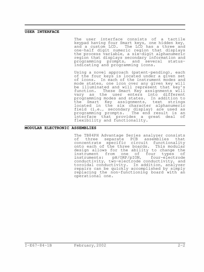
High or Low Set Point . . . . . . . . . . . . . . . . . . . . . 2-4High or Low Cycle Timer . . . . . . . . . . . . . . . . . . . . 2-4Cleaner . . . . . . . . . . . . . . . . . . . . . . . . . . . . 2-5
DAMPING . . . . . . . . . . . . . . . . . . . . . . . . . . . . . . . 2-6DIAGNOSTICS . . . . . . . . . . . . . . . . . . . . . . . . . . . . . 2-6
Analyzer . . . . . . . . . . . . . . . . . . . . . . . . . . . . 2-7Sensor . . . . . . . . . . . . . . . . . . . . . . . . . . . . . 2-7Spike Output . . . . . . . . . . . . . . . . . . . . . . . . . . 2-7
SECTION 3 - INSTALLATION . . . . . . . . . . . . . . . . . . . . . . . . 3-1INTRODUCTION . . . . . . . . . . . . . . . . . . . . . . . . . . . . 3-1SPECIAL HANDLING . . . . . . . . . . . . . . . . . . . . . . . . . . 3-1UNPACKING AND INSPECTION . . . . . . . . . . . . . . . . . . . . . . 3-2LOCATION CONSIDERATIONS . . . . . . . . . . . . . . . . . . . . . . . 3-3HAZARDOUS LOCATIONS . . . . . . . . . . . . . . . . . . . . . . . . . 3-3RADIO FREQUENCY INTERFERENCE . . . . . . . . . . . . . . . . . . . . 3-3MOUNTING . . . . . . . . . . . . . . . . . . . . . . . . . . . . . . 3-4
Pipe Mounting . . . . . . . . . . . . . . . . . . . . . . . . . 3-4Hinge Mounting . . . . . . . . . . . . . . . . . . . . . . . . . 3-5Wall Mounting . . . . . . . . . . . . . . . . . . . . . . . . . 3-6Panel Mounting . . . . . . . . . . . . . . . . . . . . . . . . . 3-7
WIRING CONNECTIONS AND CABLING . . . . . . . . . . . . . . . . . . . 3-9Power Wiring . . . . . . . . . . . . . . . . . . . . . . . . . . 3-10Analog Output Signal Wiring . . . . . . . . . . . . . . . . . . 3-11Relay Output Signal Wiring . . . . . . . . . . . . . . . . . . . 3-11
Advantage Series (TBX5) Sensor Wiring . . . . . . . . . . . . . 3-13Non-Advantage Series (TB5) Sensor Wiring . . . . . . . . . . . . 3-14
GROUNDING . . . . . . . . . . . . . . . . . . . . . . . . . . . . . . 3-17OTHER EQUIPMENT INTERFACE . . . . . . . . . . . . . . . . . . . . . . 3-17INSTRUMENT ROTATION . . . . . . . . . . . . . . . . . . . . . . . . . 3-18
SECTION 4 - OPERATING PROCEDURES . . . . . . . . . . . . . . . . . . . . 4-1INTRODUCTION . . . . . . . . . . . . . . . . . . . . . . . . . . . . 4-1

I-E67-84-1B February,2002 iv
OPERATOR INTERFACE CONTROLS REVIEW . . . . . . . . . . . . . . . . . 4-2Liquid Crystal Display (LCD) . . . . . . . . . . . . . . . . . . 4-2Multi-Function Smart Keys . . . . . . . . . . . . . . . . . . . 4-3
MODES OF OPERATION . . . . . . . . . . . . . . . . . . . . . . . . . 4-5HOLD ICON . . . . . . . . . . . . . . . . . . . . . . . . . . . . . . 4-6FAULT ICON . . . . . . . . . . . . . . . . . . . . . . . . . . . . . 4-7SPIKE ICON . . . . . . . . . . . . . . . . . . . . . . . . . . . . . 4-7RELAY ICONS . . . . . . . . . . . . . . . . . . . . . . . . . . . . . 4-7
SECTION 5 - MEASURE MODE . . . . . . . . . . . . . . . . . . . . . . . . 5-1INTRODUCTION . . . . . . . . . . . . . . . . . . . . . . . . . . . . 5-1BOREDOM SWITCH . . . . . . . . . . . . . . . . . . . . . . . . . . . 5-1PRIMARY DISPLAY . . . . . . . . . . . . . . . . . . . . . . . . . . . 5-1SECONDARY DISPLAY . . . . . . . . . . . . . . . . . . . . . . . . . . 5-2FAULT INFORMATION Smart Key . . . . . . . . . . . . . . . . . . . . . 5-2SPT Smart Key . . . . . . . . . . . . . . . . . . . . . . . . . . . . 5-2MENU Smart Key . . . . . . . . . . . . . . . . . . . . . . . . . . . 5-3
SECTION 6 - CALIBRATE MODE . . . . . . . . . . . . . . . . . . . . . . . 6-1INTRODUCTION . . . . . . . . . . . . . . . . . . . . . . . . . . . . 6-1CALIBRATE STATES OF OPERATION . . . . . . . . . . . . . . . . . . . . 6-1
Process Sensor Calibrate State . . . . . . . . . . . . . . . . . 6-3One-Point Calibrate State . . . . . . . . . . . . . . . . 6-4Two-Point Calibrate State . . . . . . . . . . . . . . . . 6-5
Temperature Calibrate State . . . . . . . . . . . . . . . . . . 6-8Edit Calibrate State . . . . . . . . . . . . . . . . . . . . . . 6-10Reset Calibrate State . . . . . . . . . . . . . . . . . . . . . 6-12Analog Output One Calibrate State . . . . . . . . . . . . . . . 6-12Analog Output Two Calibrate State . . . . . . . . . . . . . . . 6-13
SECTION 7 - OUTPUT/HOLD MODE . . . . . . . . . . . . . . . . . . . . . . 7-1INTRODUCTION . . . . . . . . . . . . . . . . . . . . . . . . . . . . 7-1OUTPUT/HOLD STATES OF OPERATION . . . . . . . . . . . . . . . . . . . 7-1
Hold/Release Hold Output State . . . . . . . . . . . . . . . . . 7-2Analog Output One Rerange State . . . . . . . . . . . . . . . . 7-6Analog Output Two Rerange State . . . . . . . . . . . . . . . . 7-7Damping State . . . . . . . . . . . . . . . . . . . . . . . . . 7-8Spike State . . . . . . . . . . . . . . . . . . . . . . . . . . 7-10
SECTION 8 - CONFIGURE MODE . . . . . . . . . . . . . . . . . . . . . . . 8-1INTRODUCTION . . . . . . . . . . . . . . . . . . . . . . . . . . . . 8-1PRECONFIGURATION DATA REQUIRED . . . . . . . . . . . . . . . . . . . 8-1
CONFIGURE VIEW/MODIFY STATE . . . . . . . . . . . . . . . . . . . . . 8-1BASIC/ADVANCED PROGRAMMING MODE . . . . . . . . . . . . . . . . . . . 8-3MODIFY CONFIGURE STATES OF OPERATION . . . . . . . . . . . . . . . . 8-4
Analyzer State (Basic/Advanced) . . . . . . . . . . . . . . . . 8-7pH Analyzer State (Basic/Advanced) . . . . . . . . . . . . 8-8ORP and pION States (Basic/Advanced) . . . . . . . . . . . 8-9Ion Concentration State (Advanced) . . . . . . . . . . . . 8-10
Temperature Sensor State (Basic/Advanced) . . . . . . . . . . . 8-12Temperature Compensation State (Basic/Advanced) . . . . . . . . 8-12
Manual Nernstian State (Basic/Advanced) . . . . . . . . . 8-13Automatic Nernstian State (Basic/Advanced) . . . . . . . . 8-14Automatic Nernstian With Solution Coefficient State (Advanced)8-15
Analog Output One State (Basic/Advanced) . . . . . . . . . . . . 8-16Linear Output State (Basic/Advanced) . . . . . . . . . . . 8-16

I-E67-84-1B February,2002 v
Non-Linear Output State (Advanced) . . . . . . . . . . . . 8-18Analog Output Two State (Basic/Advanced) . . . . . . . . . . . . 8-21Relay Output One (Basic/Advanced) . . . . . . . . . . . . . . . 8-22Relay Output Two (Basic/Advanced) . . . . . . . . . . . . . . . 8-24Relay Output Three (Basic/Advanced) . . . . . . . . . . . . . . 8-25
Setpoint Relay Output (Basic/Advanced) . . . . . . . . . . 8-27Diagnostic Relay Output (Basic/Advanced) . . . . . . . . . 8-28Cycle Timer Relay Output (Advanced) . . . . . . . . . . . 8-29Cleaner Relay Output (Advanced) . . . . . . . . . . . . . 8-31
Damping State (Basic/Advanced) . . . . . . . . . . . . . . . . . 8-33Diagnostics State (Basic/Advanced) . . . . . . . . . . . . . . . 8-35Safe Mode One State (Basic/Advanced) . . . . . . . . . . . . . . 8-35Safe Mode Two State (Basic/Advanced) . . . . . . . . . . . . . . 8-36Spike State (Advanced) . . . . . . . . . . . . . . . . . . . . . 8-36
CONFIGURATION LOCKOUT . . . . . . . . . . . . . . . . . . . . . . . . 8-37
SECTION 9 - SECURITY MODE . . . . . . . . . . . . . . . . . . . . . . . . 9-1INTRODUCTION . . . . . . . . . . . . . . . . . . . . . . . . . . . . 9-1SECURITY STATE OF OPERATION . . . . . . . . . . . . . . . . . . . . . 9-1
SECTION 10 - SECONDARY DISPLAY MODE . . . . . . . . . . . . . . . . . . . 10-1INTRODUCTION . . . . . . . . . . . . . . . . . . . . . . . . . . . . 10-1SECONDARY DISPLAY STATE OF OPERATION . . . . . . . . . . . . . . . . 10-1
SECTION 11 - SETPOINT/TUNE MODE . . . . . . . . . . . . . . . . . . . . . 11-1INTRODUCTION . . . . . . . . . . . . . . . . . . . . . . . . . . . . 11-1SETPOINT/TUNE STATES OF OPERATION . . . . . . . . . . . . . . . . . . 11-1
Setpoint Relay Output (Basic/Advanced) . . . . . . . . . . . . . 11-1Diagnostic Relay Output (Basic/Advanced) . . . . . . . . . . . . 11-3Cycle Timer Relay Output (Advanced) . . . . . . . . . . . . . . 11-4Cleaner Relay Output (Advanced) . . . . . . . . . . . . . . . . 11-6
SECTION 12 - UTILITY MODE . . . . . . . . . . . . . . . . . . . . . . . . 12-1INTRODUCTION . . . . . . . . . . . . . . . . . . . . . . . . . . . . 12-1FACTORY/USER STATE . . . . . . . . . . . . . . . . . . . . . . . . . 12-1
User State . . . . . . . . . . . . . . . . . . . . . . . . . . . 12-1Advanced/Basic Programming Mode User State . . . . . . . . 12-2Reset Configuration User State . . . . . . . . . . . . . . 12-3Reset Security User State . . . . . . . . . . . . . . . . 12-4Reset All User State . . . . . . . . . . . . . . . . . . . 12-5Soft Boot User State . . . . . . . . . . . . . . . . . . . 12-6
SECTION 13 - DIAGNOSTICS . . . . . . . . . . . . . . . . . . . . . . . . 13-1INTRODUCTION . . . . . . . . . . . . . . . . . . . . . . . . . . . . 13-1FAULT CODES . . . . . . . . . . . . . . . . . . . . . . . . . . . . . 13-1
Problem Codes . . . . . . . . . . . . . . . . . . . . . . . . . 13-2Error Codes . . . . . . . . . . . . . . . . . . . . . . . . . . 13-4Calibration Diagnostic Messages . . . . . . . . . . . . . . . . 13-5Additional Diagnostic Messages . . . . . . . . . . . . . . . . . 13-6
SECTION 14 - TROUBLESHOOTING . . . . . . . . . . . . . . . . . . . . . . 14-1INTRODUCTION . . . . . . . . . . . . . . . . . . . . . . . . . . . . 14-1ANALYZER TROUBLESHOOTING . . . . . . . . . . . . . . . . . . . . . . 14-1SENSOR TROUBLESHOOTING . . . . . . . . . . . . . . . . . . . . . . . 14-5
Visual Sensor Inspection . . . . . . . . . . . . . . . . . . . . 14-6Sensor Electronic Test . . . . . . . . . . . . . . . . . . . . . 14-7
SECTION 15 - MAINTENANCE . . . . . . . . . . . . . . . . . . . . . . . . 15-1

I-E67-84-1B February,2002 vi
INTRODUCTION . . . . . . . . . . . . . . . . . . . . . . . . . . . . 15-1PREVENTIVE MAINTENANCE . . . . . . . . . . . . . . . . . . . . . . . 15-1
Cleaning the Sensor . . . . . . . . . . . . . . . . . . . . . . 15-2
SECTION 16 - REPLACEMENT PROCEDURES . . . . . . . . . . . . . . . . . . . 16-1INTRODUCTION . . . . . . . . . . . . . . . . . . . . . . . . . . . . 16-1ELECTRONIC ASSEMBLY REMOVAL/REPLACEMENT . . . . . . . . . . . . . . . 16-1FRONT BEZEL ASSEMBLY REMOVAL/REPLACEMENT . . . . . . . . . . . . . . 16-2SHELL ASSEMBLY REMOVAL/REPLACEMENT . . . . . . . . . . . . . . . . . 16-2REAR COVER ASSEMBLY REMOVAL/REPLACEMENT . . . . . . . . . . . . . . . 16-3
SECTION 17 - SUPPORT SERVICES . . . . . . . . . . . . . . . . . . . . . . 17-1INTRODUCTION . . . . . . . . . . . . . . . . . . . . . . . . . . . . 17-1RETURN MATERIALS PROCEDURES . . . . . . . . . . . . . . . . . . . . . 17-1REPLACEMENT PARTS . . . . . . . . . . . . . . . . . . . . . . . . . . 17-1RECOMMENDED SPARE PARTS KITS . . . . . . . . . . . . . . . . . . . . 17-2
APPENDIX A - TEMPERATURE COMPENSATION . . . . . . . . . . . . . . . . . . A-1GENERAL . . . . . . . . . . . . . . . . . . . . . . . . . . . . . . . A-1NERNSTIAN TEMPERATURE COMPENSATION . . . . . . . . . . . . . . . . . A-1SOLUTION COEFFICIENT . . . . . . . . . . . . . . . . . . . . . . . . A-2
APPENDIX B - PROGRAMMING TEXT STRING GLOSSARY . . . . . . . . . . . . . . B-1GENERAL . . . . . . . . . . . . . . . . . . . . . . . . . . . . . . . B-1GLOSSARY OF PROGRAMMING TEXT PROMPTS . . . . . . . . . . . . . . . . B-1
APPENDIX C - CONFIGURATION WORKSHEETS . . . . . . . . . . . . . . . . . . C-1
Safety Summary
GENERALWARNINGS
Equipment EnvironmentAll components, whether in transportation, operation or storage,must be in a noncorrosive environment.
Electrical Shock Hazard During MaintenanceDisconnect power or take precautions to insure that contact withenergized parts is avoided when servicing.
SPECIFICCAUTIONS
To prevent possible signal degradation, separate metal conduitruns are recommended for the sensor, signal and power wiring.
Automatic Nernstian With Solution Coefficient compensation canonly be used for processes that are extremely repeatable.

I-E67-84-1B February,2002 1-1
SPECIFICWARNINGS
Use this equipment only in those classes of hazardous locationslisted on the nameplate. Uses in other hazardous locations canlead to unsafe conditions that can injure personnel and damageequipment.
Allow only qualified personnel (refer to INTENDED USER in SECTION1 - INTRODUCTION) to commission, operate, service or repair thisequipment. Failure to follow the procedures described in thisinstruction or the instructions provided with related equipmentcan result in an unsafe condition that can injure personnel anddamage equipment.
Consider the material compatibility between cleaning fluids andprocess liquids. Incompatible fluids can react with each othercausing injury to personnel and equipment damage.
Use solvents only in well ventilated areas. Avoid prolonged orrepeated breathing of vapors or contact with skin. Solvents cancause nausea, dizziness, and skin irritation. In some cases,overexposure to solvents has caused nerve and brain damage.Solvents are flammable - do not use near extreme heat or openflame.
Do not substitute components that compromise the certificationslisted on the nameplate. Invalidating the certifications can leadto unsafe conditions that can injure personnel and damageequipment.
Do not disconnect equipment unless power has been switched off atthe source or the area is known to be nonhazardous. Disconnectingequipment in a hazardous location with source power on can producean ignition-capable arc that can injure personnel and damageequipment.
Remove power from the unit and allow at least one minute for theunit to discharge before performing these procedures. Failure todo so constitutes an electrical shock hazard that can injurepersonnel and damage equipment.
Disconnect the AC line cord or power lines from the operatingbranch circuit coming from the source before attempting electricalconnections. Instruments powered by AC line voltage constitute apotential for personnel injury due to electric shock.
Keep the enclosure and covers in place after completing the wiringprocedures and during normal operation. Do not disconnect orconnect wiring or remove or insert printed circuit boards unlesspower has been removed and the flammable atmosphere is known NOTto be present. These procedures are not considered normaloperation. The enclosure prevents operator access to energizedcomponents and to those that can cause ignition capable arcs.Failure to follow this warning can lead to unsafe conditions thatcan injure personnel and damage equipment.
All error conditions are considered catastrophic. When such anerror has been reported, the analyzer should be replaced with aknown-good analyzer. The non-functional analyzer should bereturned to the factory for repair. Contact the factory for aReturn Materials Authorization (RMA) number.
SECTION 1 - INTRODUCTION

I-E67-84-1B February,2002 1-2
OVERVIEWThe TB84PH Advantage Series is a line-poweredpH/ORP/pION (i.e., specific ion) analyzer withstate-of-the-art electronics, internal andexternal diagnostic functionality, aninnovative user-interface having HotKeycapability, two user-selectable modes ofoperation, and DIN-size packaging.
Diagnostic interrogation of the internalcircuitry and external sensing devices iscontinually conducted to ensure accuracy andimmediate notification of problem situationswhen they occur. Detection of sensorintegrity includes pH electrode damage, sensorcoating, sensor out-of-liquid, ground-loopdetection, and short/open sensor cabling.Additional software functions monitor slope,asymmetric potential, process variableover/under range, and temperature over/underrange. If these diagnostic conditions occur,the analyzer can be programmed to induce arepetitive modulation of a given magnitude inthe output current or can be link to a relayoutput thus providing the ability to alertpersonnel of a problem condition.
The analyzer packaging conforms to DINstandards and has mounting options thatinclude pipe, wall, hinge, and panelinstallations. Due to the modular design ofthe electronics, changing the analyzer sensingcapability to other analytical properties suchas solution conductivity can be quick andeasy.
The user interface is an innovative, patent-pending technology which facilitates a smoothand problem-free link between the user andanalyzer functionality. The programmingstructure and multi-function keys reduceprogramming difficulties by providing a togglebetween Basic and Advanced functions.

I-E67-84-1B February,2002 1-3
INTENDED USER
InstallationPersonnel
Should be an electrician or a person familiarwith the National Electrical Code (NEC), orequivalent, and local wiring regulations.Should have a strong background ininstallation of analytical equipment.
ApplicationTechnician
Should have a solid background in pH/ORP/pIONmeasurements, electronic instrumentation, andprocess control and be familiar with propergrounding and safety procedures for electronicinstrumentation.
Operator Should have knowledge of the process andshould read and understand this instructionbook before attempting any procedurepertaining to the operation of the TB84PHAdvantage Series analyzer.
MaintenancePersonnel
Should have a background in electricity and beable to recognize shock hazards. Personnelmust also be familiar with electronic processcontrol instrumentation and have a goodunderstanding of troubleshooting procedures.
FEATURES
Diagnostic SensorCapability
The TB84PH Advantage Series analyzer offersthe necessary hardware and software for fullcompatibility with TBX5 Advantage SeriespH/ORP/pION sensors. These sensors areequipped with the new NEXT STEP referencetechnology and are well suited for harshprocess streams.
Multiple Applications Accepts inputs from standard glass pHelectrodes, antimony pH electrodes, gold orplatinum Oxidation-Reduction Potential (ORP)electrodes, or any specific ion electrode. Acustom electrode configuration is alsoavailable which uses information regarding theasymmetric potential and isopotential point.Isolated analog outputs allows use in groundedor floating circuits. Relay outputs providesetpoint control, cycle-timer control,diagnostic alarming, and cleaner operation.

I-E67-84-1B February,2002 1-4
Automatic TemperatureCompensation
Menu-selectable choices provide the user witha wide range of easily configurable selectionsfor temperature compensation.
1. Automatic Nernstian2. Automatic Nernstian with Solution
Coefficient3. Manual Nernstian
Wide Rangeability Analog output spans do not affect the displayrange of -2.00 to +16.00 pH (-2000 to +2000 mVfor ORP and specific ion). Minimum andmaximum process variable output spans are 1.0pH (100 mV for ORP and specific ion) and 14 pH(3998 mV for ORP and specific ion),respectively. Minimum and maximum temperatureoutput spans are 10 C (18 F) and 140 C (284o o o
F), respectively.o
Innovative UserInterface
Using four Smart Keys and a custom LiquidCrystal Display (LCD), multiple functions havebeen assigned to each key and are displayed atthe appropriate time depending on theprogramming environment. This patent-pendingtechnology reduces the number of keys whilemaintaining the maximum amount offunctionality and allows for the use of alarger, more visible LCD.
Simple Calibration One- and two-point calibrations are availableand smoothly guide the user through eachcalibration step. Provisions for viewing andmodifying the sensor calibration data are alsoincluded. Temperature calibration uses smartcalibration routines which determine theappropriate adjustments based on previouscalibration data.
NEMA 4X/IP65Housing
Suitable for corrosive environments, theelectronics enclosure is a corrosionresistant, aluminum alloy. A chemicalresistant polyurethane powder coating providesexternal protection.
Suitable forHazardous Locations
The TB84PH Advantage Series analyzer designcomplies with industry standards for Division2 and non-incendive installations(certification pending).
DiagnosticIndication
The custom LCD has dedicated icons which actas visible indications of an output hold,fault, diagnostic spike, and energized relaycondition.

I-E67-84-1B February,2002 1-5
Secure Operation A hardware lockout feature preventsunauthorized altering of instrumentconfiguration parameters while allowing otheranalyzer functions to be fully accessible.Software security codes can also be assignedto the Configure, Calibrate, Output/Hold, andSetpoint/Tune Modes of Operation.
Compact Packaging Industry standard ½-DIN size maintainsstandard panel cut outs and increasesinstallation flexibility by providing pipe,wall, hinge, and panel mounting options.
Nonvolatile Memory In the event of a power failure, thenonvolatile memory stores and retains theconfiguration and calibration data.
Analyzer Diagnostics Built-in electronic circuitry and firmwareroutines perform a series of self-diagnostics,monitoring such areas as memory and inputcircuit integrity. Irregularities areindicated for maintenance purposes.
EQUIPMENT APPLICATION
The TB84PH Advantage Series analyzer can beused anywhere pH, ORP, or specific ionmeasurements are desired.
INSTRUCTION CONTENT
Introduction This section provides a product overview, adescription of each section contained in thismanual, and how each section should be used.This section also has a glossary of terms andabbreviations, a list of reference documentson related equipment and/or subjects, theproduct identification (nomenclature), and acomprehensive list of hardware performancespecifications including accessories andapplicable certification information.
AnalyzerFunctionality And
Operator InterfaceControls
This section provides a short description onthe functionality of the TB84PH AdvantageSeries analyzer.
Installation This section provides information on analyzerinstallation such as unpacking directions,location considerations, analyzer mountingoptions and procedures, wiring instructions,sensor connections, and grounding procedures.

I-E67-84-1B February,2002 1-6
Operating Procedures This section addresses the operator interfacecontrols and their function. The Mode ofOperation and LCD status icons are listed andtheir functions are described.
Measure Mode This section describes the normal analyzermode of operation which includes the primaryand secondary display, Fault Information SmartKey, and Menu Smart Key functions.
Calibrate Mode This section provides sensor and analyzercalibration procedures and calibration datadescriptions.
Output/Hold Mode This section describes the Output/Hold Statesof Operation including hold, rerange, damping,and spike features.
Configure Mode This section defines the required actions toestablish and program the analyzerconfiguration.
Security Mode This section provides the procedures necessaryto set and clear analyzer security codes.
Secondary DisplayMode
This section provides the procedure necessaryto set the information displayed in secondarydisplay of the Measure Mode.
Utility Mode This section defines the reset options andBasic/Advanced programming toggle.
Diagnostics This section provides a description of thediagnostic tools available to aid withanalyzer servicing. This section alsoprovides a listing of displayed faults and thecorrective action to be taken.
Troubleshooting This section provides an analyzer and sensortroubleshooting guide to help determine andisolate problems.
Sensor Maintenance This section provides cleaning procedures forpH/ORP/pION sensors.
Repair/Replacement This section includes procedures for analyzerassembly and sensor replacement.
Support Services This section provides a list of replacementparts unique to the TB84PH Advantage Seriesanalyzer.
Appendix A This section provides temperature compensationinformation.

I-E67-84-1B February,2002 1-7
Appendix B This section provides a glossary of textprompts used in the secondary display duringanalyzer programming.
Appendix C This section provides a configurationworksheet used to record the analyzer’sconfiguration and shows default values when aconfiguration reset is performed.
HOW TO USE THIS MANUAL
For safety and operating reasons, reading andunderstanding this product instruction manualis critical. Do not install or complete anytasks or procedures related to operation untildoing so.
The sections of this product instruction aresequentially arranged as they relate toinitial start-up (from UNPACKING toREPAIR/REPLACEMENT PROCEDURES). After initialstart-up, refer to this instruction as neededby section.
GLOSSARY OF TERMS AND ABBREVIATIONSTable 1-1. Glossary of Terms and Abbreviations
Term Description
AsymmetricPotential
The electrical potential across the measuringand reference half-cells of an electrochemicalsensor at the Isopotential Point.
Boredom Switch An automatic timer built into the TB84PHAdvantage Series analyzer that returns theinstrument to the Measure Mode of Operation ifa user has entered another mode of operationand has not initiated another action fortwenty minutes.
EEPROM Electrically Erasable Programmable Read OnlyMemory. A type of non-volatile memory thatcan be electrically programmed and erased.
Efficiency A value that represents the percentage of thetheoretical, Nernstian temperature compensatedoutput from an electrochemical sensor.
EPROM Erasable Programmable Read Only Memory. Thismemory holds the operational program for themicrocontroller integral to the analyzer.
Ground Loop A path between two separate ground connectionsthus allowing unwanted current flow throughthe measurement cabling or circuitry.

Term Description
I-E67-84-1B February,2002 1-8
HotKey A short-cut that moves the user from the ViewConfigure State to the Modify Configure Stateof Operation.
Icon A text or symbolic image representing a setfunction, condition, or engineering unit.
Impedance A measure of the total opposition to currentflow in an alternating-current circuit.
IsopotentialPoint
The potential of an electrochemical sensorthat is independent to sample fluidtemperature changes.
LCD Liquid Crystal Display. The custom three andone-half digit primary display, six-characteralpha-numeric secondary field, and supportingicons that allow for local readout of theprocess variable, programming of analyzerfunctions, and local indication of fault,hold, and relay state conditions.
Non-volatileMemory
Memory that retains programmed informationsuch as configuration and calibrationparameters, even when power is removed.
ORP Oxidation-Reduction Potential. The potentialcreated during a chemical reaction in whichone or more electrons are transferred from oneatom or molecule to another.
PCB Printed Circuit Board. A flat board whichcontains pads for integrated circuit chips,components, connections, and electricallyconductive pathways between those elementsthat function together to form an electroniccircuit.
pH Potential of Hydrogen. A measure of theacidity or alkalinity of a solution,numerically equal to 7 for neutral solutions,increasing with increasing alkalinity anddecreasing with increasing acidity.
RTD Resistive Temperature Detector. An elementwhose resistance has a relationship with thetemperature of its surroundings.
SEEPROM Serial Electrically Erasable Programmable ReadOnly Memory. A type of non-volatile memorythat can be electrically programmed, erased,and read using serial communicationtechniques.


I-E67-84-1B February,2002 1-10
| | | | | | | | | InputP H | | | | | | | pH/ORP/pIONE C | | | | | | | Four-Electrode ConductivityT E | | | | | | | Two-Electrode ConductivityT C | | | | | | | Toroidal Conductivity
| | | | | | | Programming1 | | | | | | Basic2 | | | | | | Advanced
| | | | | | Reserved (PI Controller)0 | | | | | None
| | | | | Reserved (Remote Analyzer)0 | | | | None
| | | | Housing Type0 | | | Powder Coated, Alodined
| | | Aluminum| | | Mounting Hardware0 | | None1 | | Pipe2 | | Hinge3 | | Panel4 | | Wall
| | Agency Approval (Pending)0 | None1 | FM2 | CSA
3 | CENLEC| Label0 None1 Stainless Steel2 Mylar
NOTE: A single digit or letter must be used in each nomenclature position.

I-E67-84-1B February,2002 1-11
SPECIFICATIONS
Table 1-3. SpecificationsProperty Characteristic/Value
Process Display RangepH -2 to +16.00 pHORP -1999 to +1999 mVpION -1999 to +1999 mV
Temperature 0 to 140 C (32 to 284 F).Display Range
o o o o
Resolution, DisplaypH 0.01 pHORP 1 mVpION 1 mVTemperature 1 C, 1 F.o o
Accuracy, DisplaypH ±0.01 pHORP ±1 mVpION ±1 mVTemperature 1 C
Accuracy, Output ±0.02 mA at full scale output setting
o
Nonlinearity, DisplaypH ±0.01 pHORP ±1 mVpION ±1 mVTemperature 1 C
Nonlinearity, Output ±0.02 mA at full scale output setting
o
Repeatability, DisplaypH ±0.01 pHORP ±1 mVpION ±1 mVTemperature 1 C
Repeatability, Output ±0.02 mV at full scale output setting
o
Stability, DisplaypH ±0.01 pHORP ±1 mVpION ±1 mVTemperature 1 C
Stability, Output ±0.02 mV at full scale output setting
o
Temperature Manual NernstianCompensation Automatic Nernstian
Automatic Nernstian with Solution Coefficient
Input TypespH Glass, Antimony, Custom Isopotential & Asymmetric
ORP Platinum, GoldpION Sodium, Chloride, Sulfide, etc.Temperature 3 kohm Balco, Pt100
Potential
Dynamic Response 3 sec. for 90% step change at 0.0 sec. damping.
Ambient TemperatureEffectpH ±0.007 pH/ C @ 95% Relative HumidityORP ±0.4 mV/ C @ 95% Relative HumiditypION ±0.4 mV/ C @ 95% Relative HumidityTemperature ±0.16 C/ C @ 95% Relative HumidityOutput ±0.008 mA/ C @ 95% Relative Humidity
o
o
o
o o
o

Property Characteristic/Value
I-E67-84-1B February,2002 1-12
Output Minimum SpanpH 1.00 pHORP 100 mVpION 100 mVTemperature 10 Co
Output Maximum Span(full scale settings)pH 14 pH (0 to 14 pH)ORP 3998 mV (-1999 to 1999 mV)pION 3998 mV (-1999 to 1999 mV)Temperature 140 C, 284 F (0 to 140 C, 32 to 284 F)o o o o
Damping Continuously adjustable from 0.0 to 99.9 seconds
Supply Voltage Ranges 93.5 to 276 Vac, 50 to 60 Hz, Single PhaseMaximum Consumption 17 VA
Analog Output Ratings Two completely isolated 0/4 to 20 mAdc outputs750 ohms Maximum Load ValueOutput One Fixed to the Process VariableOutput Two Software-Selectable to either the ProcessVariable or Temperature
Relay Output Ratings Three SPDT contacts with LCD icon indicatorsHardware configurable for Normally Open or NormallyCloseSoftware configurable relay functions include High/LowSetpoint with adjustable Deadband and Time Delay,High/Low Cycle Timer with adjustable Duty Cycle andTime Delay, Diagnostic Alarm, and Cleaner ControlMaximum AC Capacity Values of 100 VA, 240 Vac, and 3 AMaximum DC Capacity Values of 50 W, 24 Vdc, and 3 A
Power Supply Effect ±0.005% of full scale span per volt
Turn-On Time 2 seconds typical, 4 seconds maximum
Maximum Sensor Cable 100 ft (30.5 m)Length
Sensor DiagnosticpH Glass and Reference Impedance, Open and Short Cabling,
ORP Reference Impedance, Open and Short Cabling,
pION Reference Impedance, Open and Short Cabling,
Efficiency and Asymmetric Potential Check
Efficiency and Asymmetric Potential Check
Efficiency and Asymmetric Potential Check
Diagnostic Notification Local indication via a FAULT and SPIKE icon.Analog Mode
Programmable output pulse on Analog Output One,0 to 16 mA for 1 seconds on 6 second cycles
EnvironmentalOperating temperature -20 to 60 C (-4 to 140 F)LCD Range -20 to 60 C (-4 to 140 F)Storage temperature -40 to 70 C (-40 to 158 F)
o o o o
o o o o
o o o o
Mounting Effect None
Enclosure NEMA 4XClassification IP65
SizeHeight 144 mm high x 144 mm wide x 171 mm long (5.67 in. high
Minimum panel depth 145 mm (5.70 in.)Maximum panel cutout 136.7 mm x 136.7 mm (5.38 in. x 5.38 in.).
x 5.67 in. wide x 6.75 in. long)

Property Characteristic/Value
I-E67-84-1B February,2002 1-13
Weight 4.2 lb (1.9 kg) without mounting hardware7.5 lb (3.4 kg) with Pipe Mounting Hardware
EMC Requirements CE certified:Electromagnetic Emission - EN50082-1: 1994EN55011: 1991 (CISPR11: 1990) Class A
Electromagnetic Immunity - EN50082-2: 1996EN61000-4-2: 1995 6 kV Contact
6 kV IndirectEN61000-4-3: 1997 10 V/m (unmodulated, rms)
80 to 1000 MHZEN61000-4-4: 1995 1 kV Signal Lines
5/50 T /T nSr h5 kHz
EN61000-4-8: 1994 50 Hz30A(rms)/m
ENV50141: 1994 10 V (unmodulated, rms)0.15 to 80 MHZ80% AM (1kHz)150 ohms, source impedance
ENV50204: 1996 10 V/m (unmodulated, rms)900 ±5 MHZ50% duty cycle200 Hz
Low Voltage - EN61010-1:1993 (Category II)
Agency Approvals1
(pending)FM Non-incendive.
CSA Class I, Division 2, Groups A, B, C, and D. Class II,
Class I, Division 2, Groups A, B, C, and D. Class II,Division 2, Groups F and G. Class III, Division 2.
Division 2, Groups E, F and G. Class III, Division 2.
SPECIFICATIONS SUBJECT TO CHANGE WITHOUT NOTICE1. Hazardous location approvals for use in flammable atmospheres are for ambientconditions of -25 to 40 C (-13 to 104 F), 86 to 108kPa (12.5 to 15.7 psi) with ao o o o
maximum oxygen concentration of 21%.

I-E67-84-1B February,2002 1-14
ACCESSORIES
Kits Part Number Mounting Kit
4TB9515-0124 Pipe
4TB9515-0125 Hinge
4TB9515-0156 Wall
4TB9515-0123 Panel
Part Number Description
4TB9515-0164 BNC Adapter
4TB9515-0166 BNC Adapter w/ ½" Cord Grip Fitting
4TB9515-0165 ½" Cord Grip Fitting
4TB9515-0191 PG9 Cord Grip Fitting
4TB9515-0198 Complete Cord Grip Set (Three PG9 p/n4TB9515-0191 & Two ½” p/n 4TB9515-0165)
See Section 17, Support Services, for acomplete list of available kits.
Sensors Nomenclature Fitting Type1
TBX551, TB551 In-line Twist Lock, Submersible
TBX556, TB556 In-line Threaded, Submersible
TBX557, TB557 Ball Valve Insertion, Hot Tap
TBX561, TB561 Sterilizable, In-line
TBX564, TB564 High Pressure Hot Tap
TBX567, TB567 High Pressure In-line
TBX5 Advantage Series Sensors required for advanced1
sensor diagnostics. BNC Adapter Kit required for TB5Sensors with BNC Connector. When using TB5 Sensors withtype T (i.e., Pin Lug) terminations, the BNC Adapter p/n4TB9515-0164 is not required. See Section 3,Installation, for more information.

I-E67-84-1B February,2002 1-15

I-E67-84-1B February,2002 2-1
SECTION 2 - ANALYZER FUNCTIONALITY ANDOPERATOR INTERFACE CONTROLS
INTRODUCTION
The beginning of this section contains anoverview of the TB84PH pH/ORP/pION AdvantageSeries analyzer functionality and importantinformation for configuration personnel. Thelatter part of this section discusses theoperator interface controls. It includesdescriptions of the analyzer modes andfaceplate controls.
ANALYZER OVERVIEW
The TB84PH Advantage Series analyzer providestwo analog output signals that can beconfigured to be proportional to either theoutput of any electrochemical sensor having aDC voltage output between -2000 and +2000 mVand/or a 3k Balco or Pt100 RTD. This includessensors requiring electrometer type detectorssuch as pH, ORP, and specific ion (i.e., pION)sensors. In addition to the two analogoutputs, any of the three integral relayoutputs can be configured as a high or lowsetpoint controller, cycle-timer controller,diagnostic alarm, or cleaner controller. Inthis manner, the TB84PH Advantage Seriesanalyzer provides a means by which to monitorand control the pH, ORP, pION, or IonConcentration of a process fluid. This analyzer is equipped with internaldiagnostic capabilities allowing for thedetection of any potential problems with theelectronics and operation of firmware.Diagnostic capability also includes thedetection of sensor integrity such as pH glasselectrode impedance, reference electrodeimpedance, ground-loop detection, open andshorted cabling, process variables out ofrange, and incorrect calibration values.
I-E67-84-1B February,2002 2-2
USER INTERFACE
The user interface consists of a tactilekeypad having four Smart keys, one hidden key,and a custom LCD. The LCD has a three andone-half digit numeric region that displaysthe process variable, a six-digit alphanumericregion that displays secondary information andprogramming prompts, and several status-indicating and programming icons.
Using a novel approach (patent-pending), eachof the four keys is located under a given setof icons. In each of the instrument modes andmode states, one icon over any given key willbe illuminated and will represent that key’sfunction. These Smart Key assignments willvary as the user enters into differentprogramming modes and states. In addition tothe Smart Key assignments, text stringslocated in the six character alphanumericfield (i.e., secondary display) are used asprogramming prompts. The end result is aninterface that provides a great deal offlexibility and functionality.
MODULAR ELECTRONIC ASSEMBLIES
The TB84PH Advantage Series analyzer consistsof three separate PCB assemblies thatconcentrate specific circuit functionalityonto each of the three boards. This modulardesign allows for the ability to change theinstrument from one of four types ofinstruments: pH/ORP/pION, four-electrodeconductivity, two-electrode conductivity, andtoroidal conductivity. In addition, analyzerrepairs can be quickly accomplished by simplyreplacing the non-functioning board with anoperational one.


I-E67-84-1B February,2002 2-8

I-E67-84-1B February,2002 3-1
SECTION 3 - INSTALLATION
INTRODUCTION
This section of the manual will aide the userin all levels of the installation process.The intention is to provide simple proceduresfor placing the TB84PH Advantage Seriesanalyzer into service.
SPECIAL HANDLING
Besides the normal precautions for storage andhandling of electronic equipment, the analyzerhas special static sensitive device (SSD)handling requirements. This equipmentcontains semiconductors subject to damage bydischarge of static electricity; therefore,avoid direct contact with terminal blockconductors and electronic components on thecircuit board.
To minimize the chances of damage by staticelectricity, follow these techniques duringwiring, service, troubleshooting, and repair.
1. Remove assemblies containingsemiconductors from their protectivecontainers only:
a. When at a designated static-free workstation.
b. After firm contact with an antistaticmat and/or gripped by a grounded individual.
2. Personnel handling assemblies withsemiconductors must be neutralized to astatic-free work station by a grounding wriststrap connected to the station or to a goodground point at the field site.
3. Do not allow clothing to make contactwith semiconductors. Most clothing generatesstatic electricity.
4. Do not touch connectors, circuit traces,and components.

I-E67-84-1B February,2002 3-2
5. Avoid partial connection ofsemiconductors. Semiconductors can be damagedby floating leads. Always install electronicassemblies with power removed. Do not cutleads or lift circuit paths whentroubleshooting.
6. Ground all test equipment.
7. Avoid static charges during maintenance.Make sure the circuit board is thoroughlyclean around its leads but do not rub or cleanwith an insulating cloth.
NOTE: An antistatic field service kit, ABB part number1948385_1, is available for personnel working ondevices containing static sensitive components. Thekit contains a static dissipative work surface (mat),a ground cord assembly, wrist bands, and alligatorclip.
UNPACKING AND INSPECTION
Examine the equipment upon receipt forpossible damage in transit. File a damageclaim with the responsible transportationcompany, if necessary. Notify the nearest ABBsales office.
Carefully inspect the packing material beforediscarding it to make certain that allmounting equipment and any specialinstructions or paperwork have been removed.Careful handling and installation will insuresatisfactory performance of the unit.
Use the original packing material andcontainer for storage. Select a storageenvironment free of corrosive vapors andextreme temperature and humidity. Storagetemperature must not exceed -40 degrees to +70degrees Celsius (-40 degrees to +158 degreesFahrenheit).
Remove the protective film from the analyzerlens after the analyzer has been placed in itsfinal installed location.
I-E67-84-1B February,2002 3-3
LOCATION CONSIDERATIONS
When mounting the unit, leave ample clearancefor removal of the front bezel and rear cover.Signal wiring should not run in conduit oropen trays where power wiring or heavyelectrical equipment could contact orinterfere with the signal wiring. Twisted,shielded pairs should be used for the bestresults.
The mounting location should provide easyaccess for maintenance procedures and not bein a corrosive environment. Excessivemechanical vibrations and shocks as well asrelay and power switches should not be in theimmediate area. Additionally, this locationmust conform to the temperature and humidityconstraints listed in the Table 1-3,Specifications.
HAZARDOUS LOCATIONS
WARNING Use this equipment only in those classes ofhazardous locations listed on the nameplate.Installations in hazardous locations otherthan those listed on the nameplate can leadto unsafe conditions that can injurepersonnel and damage equipment.
Refer to Table 1-3, Specifications, in Section1 for a list of certifications and approvalsapplicable to the TB84PH Advantage Seriesanalyzer.
RADIO FREQUENCY INTERFERENCE
Most electronic equipment is affected to someextent by radio frequency interference (RFI).Caution should be exercised with regard to theuse of portable communications equipment inareas where this electronic equipment is beingused. Post appropriate cautions in the plantas required.

I-E67-84-1B February,2002 3-4
MOUNTING
The TB84PH Advantage Series analyzer can bepipe, hinge, wall, or panel mounted. Figure3-1 shows the overall dimensions of the TB84PHwithout mounting hardware. Mounting hardwareattaches to the four sets of threaded holeslocated on the corners of the main housing.
Figure 3-1. Overall DimensionsPipe Mounting
The TB84PH Pipe Mount Kit (p/n 4TB9515-0124)contains a pipe and instrument mountingbracket with associated hardware. The pipemounting bracket can be fitted to pipe sizesas large as two-inches.
Using Figure 3-2 as a reference, mount theTB84PH analyzer as follows:
1) Select the desired orientation of theTB84PH analyzer.
2) Attach the instrument mounting bracket tothe pipe mounting bracket using the supplied3/8" x 3/4" bolts, 3/8" flat washers, 3/8"lock washers, and 3/8" nuts.
3) Attach the pipe mounting bracket to thepipe using the supplied 5/16" U-bolts, 5/16"flat washers, 5/16" lock washers, and 5/16"nuts.
4) Attach the instrument to the instrumentmounting bracket using the supplied 3/8" x5/8" bolts, 3/8" flat washers, and 3/8" lockwashers.

5/16" U-BOLT4TB4704-0096
PIPE MOUNTBRACKET
4TB5008-0022
MOUNTBRACKET
4TB5008-0071
PIPE
3/8" X 3/4"BOLT
4TB4704-0086
3/8" X 5/8"BOLT
4TB4704-0119(4 TYP)
(2 TYP)
(4 TYP)
5/16"FLATWASHER4TB4710-0025
5/16"LOCKWASHER4TB4710-0023
(4 TYP)
(4 TYP)
3/8" NUT4TB4711-0020
(4 TYP)
3/8"FLATWASHER4TB4710-0028
(8 TYP)
3/8"LOCKWASHER4TB4710-0022
(8 TYP)
INSTRUMENT
I-E67-84-1B February,2002 3-5
Figure 3-2. Pipe Mount Installation DiagramHinge Mounting
The TB84PH Hinge Mount Kit (p/n 4TB9515-0125)contains L- and instrument mounting brackets,a stainless steel hinge, and associatedhardware. The Hinge Mount Kit allows for aclear view of the display while maintainingeasy access to the rear of the instrument.
Using Figure 3-3 as a reference, mount theTB84PH analyzer as follows:
1) Select the desired location and orientationof the TB84PH analyzer.
2) Attach the L-bracket to the selectedlocation using the appropriate type offastener based on the mounting surfacematerial.
3) Attach the stainless steel hinge to the L-bracket using the supplied 3/8" x 3/4" bolts,3/8" flat washers, 3/8" lock washers, and 3/8"nuts.
4) Attach the instrument mounting bracket tothe stainless steel hinge using the supplied3/8" x 3/4" bolts, 3/8" flat washers, 3/8"lock washers, and 3/8" nuts.
5) Attach the instrument to the instrument

L - BRACKET4TB5008-0073
MOUNTBRACKET
4TB5008-0071
3/8" X 5/8"BOLT
4TB4704-00483/8" X 3/4"
BOLT4TB4704-0086
(8 TYP)
(4 TYP)
3/8" NUT4TB4711-0020
(8 TYP)3/8"
FLATWASHER4TB4710-0028
(12 TYP)
3/8"LOCKWASHER4TB4710-0022
(12 TYP)
S.S. HINGE4TB5010-0005
WALL
TOP VIEW FRONT VIEWFASTENERS FORWALL (SUPPLIED
BY OTHERS)
INSTRUMENT
I-E67-84-1B February,2002 3-6
mounting bracket using the supplied 3/8" x5/8" bolts, 3/8" flat washers, and 3/8" lockwashers.
Figure 3-3. Hinge Mount Installation DiagramWall Mounting
The TB84PH Wall Mount Kit (p/n 4TB9515-0156)contains an instrument mounting bracket withassociated hardware. Wall mountingaccommodates installations where the analyzercan be positioned for a clear line of sightand free access to the rear terminations.These types of installation include supportingbeams, flange brackets, and wall ends.

MOUNTBRACKET
4TB5008-0071
WALL
FASTENERS FOR WALL(SUPPLIED BY OTHERS)
3/8" X 5/8"BOLT
4TB4704-0119(4 TYP)
3/8"FLATWASHER4TB4710-0028
(4 TYP)
3/8"LOCKWASHER4TB4710-0022
(4 TYP)
INSTRUMENT
I-E67-84-1B February,2002 3-7
Using Figure 3-4 as a reference, mount theTB84PH analyzer as follows:
1) Select the desired location and orientationof the TB84PH analyzer.
2) Attach the instrument mount bracket to theselected location using the appropriate typeof fastener based on the mounting surfacematerial.
3) Attach the instrument to the instrumentmounting bracket using the supplied 3/8" x5/8" bolts, 3/8" flat washers, and 3/8" lockwashers.
Figure 3-4. Wall Mount Installation DiagramPanel Mounting
The TB84PH Panel Mount Kit (p/n 4TB9515-0123)contains four panel bracket assemblies and apanel gasket. The TB84PH enclosure conformswith DIN sizing and requires a 135.4 mm x135.4 mm cut-out for panel mounting. Thepanel brackets accommodate a maximum panelthickness of 3/8".
Using Figure 3-5 as a reference, mount theTB84PH analyzer as follows:
1) Select the desired location of the TB84PHanalyzer.

CUT OUT
REAR VIEW
+0.05/-0.03
+1.3/-0.8
+1.3/-0.8
+0.05/-0.03
I-E67-84-1B February,2002 3-8
2) Cut a 135.4 mm x 135.4 mm hole withdiagonal corners through the panel as shown inFigure 3-5.
3) Install the panel gasket onto theinstrument.
4) Remove Rear Cover if necessary, and insertthe instrument through the panel cut-out.
5) Attach the panel mounting bracket assemblyto all four corners of the analyzer.
6) Tighten the adjustment screws on the panelmounting brackets until the analyzer seatsagainst the panel. Note, do not over-tightenthe adjustment screws or damage to thebrackets and panel may result.
Figure 3-5. Panel Mount Installation Diagram

I-E67-84-1B February,2002 3-9
WIRING CONNECTIONS AND CABLING
CAUTION To prevent possible signal degradation,separate metal conduit runs are recommendedfor the sensor, signal, and power wiring.
Under ideal conditions, the use of conduit andshielded wire may not be required. However,to avoid noise problems, power, signal, andoutput wiring should be enclosed in separateconduit. Just prior to entering the housing,rigid conduit should be terminated and ashort length of flexible conduit should beinstalled to reduce any stress to the housing.
Note: To maintain a NEMA 4X/IP65 rating, use approvedconduct connections or cord grips that have the same typeof ratings.
Power and signal wiring must bear a suitablevoltage rating, have a maximum temperaturerating of 75 C (167 F), and must be ino o
accordance with all NEC requirements orequivalent for the installation site. Useeither a standard three-prong groundedflexible CSA certified line cord or equivalentfor power supply connection or hard wiredirectly to the AC supply. If hard wiring theAC power supply, use stranded, 14 AWG copperconductor wire.
Signal wiring should not be run in the sameconduit or open trays where power wiring forhigh amperage electrical equipment exists.Ensure the final installation of signal andpower wiring prevents physical and/orelectrical interfere.
Note: Use weatherproof connections for all wiring ports.Heyco RLTF ½" and LTF 9 cable grips are available throughABB Inc.. See Section 17, Support Services.
The TB84PH Advantage Series analyzer acceptswire sizes 12 to 24 AWG. Signal wiring shouldalways be twisted, shielded pairs to ensurethe best performance. Pin-style terminals arerecommended for all connections and availableas kits from the factory. See section 17,Support Services, for more information.
Power Wiring

I-E67-84-1B February,2002 3-10
WARNING Disconnect the AC line cord or power linesfrom the operating branch circuit coming fromthe source before attempting electricalconnections. Instruments powered by AC linevoltage constitute a potential for personnelinjury due to electric shock.
WARNING Keep the enclosure and covers in place aftercompleting the wiring procedures and duringnormal operation. Do not disconnect orconnect wiring or remove or insert printedcircuit boards unless power has been removedand the flammable atmosphere is known NOT tobe present. These procedures are notconsidered normal operation. The enclosureprevents operator access to energizedcomponents and to those that can causeignition capable arcs. Failure to followthis warning can lead to unsafe conditionsthat can injure personnel and damageequipment.The TB84PH Advantage Series analyzer does notrequire pre-setting a jumper to acceptdifferent line-power voltages. Powerconnections are located in the back of theinstrument housing. The terminal block labelidentifies all line power, output signal, andsensor connections.
Notes:1. ABB recommends installing a power line switch forsafety purposes and for providing power-up and power-downconvenience when servicing the analyzer.
2. Do not power the system from a transformer that alsopowers large motor loads (over five horsepower) or anyother type of equipment that generates line voltagesurges, sags and excessive noise.
Using Figure 3-7 as a reference, make linepower connections as follows:
1) Strip wire insulation back approximately0.250" (seven millimeters) to ensure the barewire will make good contact with the InsulatedPin Lug terminals and will not be exposedbeyond the pin insulator.
2) Crimp Pin Lug terminals to wire usingPanaduit CT 570 or equivalent.
3) Connect the specified line voltage toTB1-1 (Line - L1), the neutral to TB1-2(Neutral - L2), and the ground to terminalTB1-3 (Chassis Ground).

I-E67-84-1B February,2002 3-11
Analog Output Signal Wiring
The terminal block label identifies the analogoutput connections. Terminal polarity isshown and must be observed to ensure properoperation. The maximum load resistance forthe analog outputs is specified in Table 1-3,Specifications. The maximum load resistancemust include all devices and wiring within theanalog output current loop. See Figure 3-7for a wiring diagram.
Using Figure 3-7 as a reference, make analogoutput connections as follows:
1) Strip wire insulation back approximately0.250" (seven millimeters) to ensure the barewire will make good contact with the InsulatedPin Lug terminals and will not be exposedbeyond the pin insulator.
2) Crimp Pin Lug terminals to the wire usingPanaduit CT 570 or equivalent.
3) Connect the wiring to the appropriateanalog output terminals.
Relay Output Signal Wiring
The relay outputs are shipped from the factoryin the default state of Normally Open. Thatis, the relay contacts will be open when therelay is not energized. To change the normalstate of any of the three relay outputs,switches on the power supply PCB assembly mustbe moved to different positions.
CARSON CITY, NV.
TAG
NORMALLY OPENSTATE
NORMALLY CLOSEDSTATE
J301
J302
J303
Shell Assembly With RearCover Assembly Attached
Bezel Assembly With Microprocessor PCB And
(Input PCB Assembly Removed For Clarity) Power Supply PCB Assemblies Attached
J303
J301
I-E67-84-1B February,2002 3-12
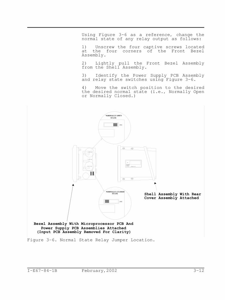
Using Figure 3-6 as a reference, change thenormal state of any relay output as follows:
1) Unscrew the four captive screws locatedat the four corners of the Front BezelAssembly.
2) Lightly pull the Front Bezel Assemblyfrom the Shell Assembly.
3) Identify the Power Supply PCB Assemblyand relay state switches using Figure 3-6.
4) Move the switch position to the desiredthe desired normal state (i.e., Normally Openor Normally Closed.)
Figure 3-6. Normal State Relay Jumper Location.

I-E67-84-1B February,2002 3-13
Using Figure 3-7 as a reference, make relayoutput connections as follows:
1) Strip wire insulation back approximately0.250" (seven millimeters) to ensure the barewire will make good contact with the InsulatedPin Lug terminals and will not be exposedbeyond the pin insulator.
2) Crimp Pin Lug terminals to the wire usingPanaduit CT 570 or equivalent.
3) Connect the wiring to the appropriaterelay output terminals.
Advantage Series (TBX5) Sensor WiringInstrument connections for the sensor wiringare located next to the signal connections.Sensor wiring should be run in shieldedconduit, or similar, for protection fromenvironmental influences. Do not allow thewires to become wet. The wiring should notlay on the ground or over any other equipment.Ensure cables are not abraded, pinched or bentduring the installation process or duringnormal operation.
The sensor cable has seven leads with pinterminals that must be connected to theterminal block in the rear cavity of theTB84PH Advantage Series analyzer. The sevenleads are color coded and have the followingfunctions and connections:
Terminal Block Sensor Color FunctionLocation Code
TB2-1 Blue Sense
TB2-2 Yellow Guard
TB2-3 Black Reference
TB2-4 Green Solution Ground
TB2-5 Red RTD
TB2-6 White RTD
TB2-7 Hvy Grn Shield
TB2-8 N/A N/A
Remove the protective insulator from the Blacklead before installing it into the analyzer’sterminal block. The insulator has beenprovided to prevent shorting of the sensorhalf-cell. Shorting of this conductor will

(L2)
(L1)
REAR VIEW
SENSOR CABLE TOBE SEALED IN
INTERNAL GROUNDTERMINALSEXTERNAL
GROUNDTERMINAL
LINENEUTRALEARTH
INPUTPOWER
CONTROLPROCESSRECORDER DEVICE
ANNUNCIATOR ANNUNCIATOR ANNUNCIATOR
1
345678
BLUE
YELLOW
BLACK
GREEN
RED
WHITE
HVY GRN
2
SENSOR CONNECTIONSTB2
POWER/OUTPUTCONNECTIONS
TB32175 LOCKHEED WAY
CARSON CITY, NV 89706
SENSEGUARDREF
SOL GNDRTDRTD
SHIELD
1
345678
2
1(+)
1(-)
2(+)
2(-)
1
2
910
3
3
1
32
LINE
CHASSIS GROUND
TB1
2
1
NEUTRAL
I-E67-84-1B February,2002 3-14
permanently damage the sensor.
Figure 3-7. Instrument Wiring Diagram.Non-Advantage Series (TB5) Sensor Wiring
For standard and Next Step ABB sensors (i.e.,TB5), a pin terminal option is available forinstallation to a TB84PH Advantage Seriesanalyzer. Though this cable option isrecommended when using a non-Advantage Seriessensor, stocking preferences may tend towardsthe use of one common sensor. If this sensortype requires a BNC connector to mate withexisting instrumentation, a BNC Adapter(included with all TB84PH Advantage Seriesanalyzers) provides such a connection.
When using the pin terminal sensor cableoption (i.e., the T[][] nomenclature optionwhere [][] represents the cable length),connect color coded leads to the analyzer’sterminal block as follows:
Terminal Block Sensor Color FunctionLocation Code
TB2-1 Blue Sense
TB2-2 N/A Guard
TB2-3 Black Reference
TB2-4 N/A Solution Ground
TB2-5 Red (If RTDApplicable)*
I-E67-84-1B February,2002 3-15
TB2-6 White (If RTDApplicable)*
TB2-7 N/A Shield
TB2-8 N/A N/A
Note: Red and White conductors will only be present if*
a temperature compensator is being using.
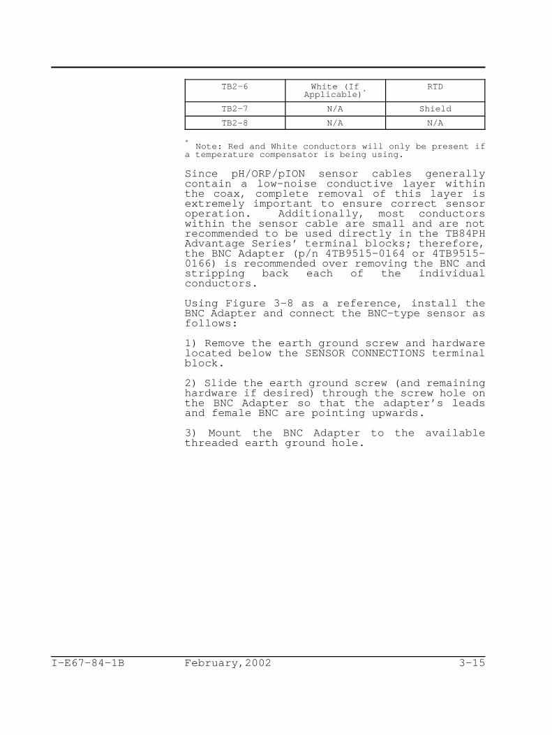
Since pH/ORP/pION sensor cables generallycontain a low-noise conductive layer withinthe coax, complete removal of this layer isextremely important to ensure correct sensoroperation. Additionally, most conductorswithin the sensor cable are small and are notrecommended to be used directly in the TB84PHAdvantage Series’ terminal blocks; therefore,the BNC Adapter (p/n 4TB9515-0164 or 4TB9515-0166) is recommended over removing the BNC andstripping back each of the individualconductors.
Using Figure 3-8 as a reference, install theBNC Adapter and connect the BNC-type sensor asfollows:
1) Remove the earth ground screw and hardwarelocated below the SENSOR CONNECTIONS terminalblock.
2) Slide the earth ground screw (and remaininghardware if desired) through the screw hole onthe BNC Adapter so that the adapter’s leadsand female BNC are pointing upwards.
3) Mount the BNC Adapter to the availablethreaded earth ground hole.

I-E67-84-1B February,2002 3-16
4) Connect the BNC Adapter pin terminals tothe corresponding SENSOR CONNECTIONS terminalblock locations via the conductor colorcoding.
Note: If the sensor does not have a femaleconnector for the Temperature Compensator(TC), connect the leads from the sensordirectly to the terminal block locations TB2-5and TB2-6 (i.e., Red and White). For sensorswithout TC, leave TB2-5 and TB2-6 open.
Figure 3-8. BNC Adapter Installation and Wiring Diagram
5) Connect the male BNC from the sensor to thefemale BNC from the BNC Adapter and the femaleTC connector from the sensor to the male TCconnector from the BNC Adapter.
6) Slide the protective boot over the BNCconnection to prevent any possible shorting toearth surfaces.
Note, if the BNC surface is in contact with aearth ground surface, a ground loop throughthe sensor may occur and could result in poorsensor performance and shortened sensor life.

I-E67-84-1B February,2002 3-17
GROUNDING
The customer and/or wiring contractor isresponsible to ensure that the analyzer,associated control or test equipment, and allexposed conductive materials are properlygrounded. Grounding procedures should be inaccordance with local regulations such as theNational Electrical Code (NEC), CanadianElectrical Code (CEC), or equivalent.Equipment installation must not pose a hazard,including under fault conditions, to operationand service personnel.
Signal wiring should be grounded at any onepoint in the signal loop or may be ungrounded(floating) if electrical noise is minimal.
The analyzer enclosure must be grounded to anearth ground having less than 0.2 ohms ofresistance. Internal and external earthground terminals are provided and shown inFigure 3-7.
Notes:
1. Because of the prevailing differences in soilconditions and in acceptable grounding practicesthroughout the world, the scope of this productinstruction does not intended to be used to describegrounding electrode systems. The customer is responsibleto ensure a grounding electrode system is acceptable tothe local building and wiring codes.
2. Using the structural metal frame of a building as therequired equipment grounding conductor for the analyzer isnot advised.
OTHER EQUIPMENT INTERFACE
The TB84PH Advantage Series analyzer providestwo isolated current outputs that areproportional to the process variable(s).Since the analyzer output is isolated, eachcurrent loop may have a maximum of one non-isolated device within its circuit. Themaximum load on the each current loop must notexceed the specification listed in Table 3-1,Specifications.

NO ROTATION
270 ROTATION
90 ROTATION
180 ROTATION
I-E67-84-1B February,2002 3-18
INSTRUMENT ROTATION
The TB84PH Advantage Series analyzer has fourpairs of threaded mounting holes in enclosure.Since these holes are located at the cornersof the instrument, the TB84PH Advantage Seriesanalyzer can be positioned in any of the fourpositions as demonstrated in Figure 3-9.
Figure 3-9. Mounting Rotation (Pipe Mount Shown)

I-E67-84-1B February,2002 4-1
SECTION 4 - OPERATING PROCEDURES
INTRODUCTION
The TB84PH Advantage Series analyzer has sevenmain operating modes: Measure, Calibration,Output/Hold, Configuration, Security,secondary Display, and Setpoint/Tune. Withineach mode, several programming statescontaining functions specific to the relatedmode are available.
The TB84PH Advantage Series analyzer isequipped with a built-in user interfacethrough which all analyzer functions areprogrammed or monitored. In order to maximizethe viewing area and minimize the space neededfor the keypad, the interface is based on acustom LCD that contains a group of two ormore icons for each button on the four buttonkeypad. Each icon represent a key functionthat is energized when that function isrequired (patent-pending).
Two display regions in the custom LCD handlethe majority of instrument functions. Theseregions include a primary display area for theprocess variable (e.g., pH) and a secondarydisplay area for programming text prompts orauxiliary information.
In addition to the user-friendly interface,the TB84PH Advantage Series analyzer isequipped with a group of icons that alerts theuser to an existing FAULT condition,diagnostic SPIKE output, output HOLDcondition, or activated RELAY. These iconsare located at the top of the LCD and are onlyenergized when the specified condition isdetected. FAULT conditions are shown in thesecondary display using the FAULT INFO keywhen the instrument is in the Measure Mode ofOperation.

MEASURE
CONFIGURE
SECURITY
OUT/HOLD
SPT/TUNE
CALIBRATE
OO
DISPLAY
I-E67-84-1B February,2002 4-2
OPERATOR INTERFACE CONTROLS REVIEW
Liquid Crystal Display (LCD)
The LCD contains nine regions that provide theuser with information on the process variable,engineering units, mode of operation, outputhold condition, fault indication, relayactivation, secondary variable, and keyfunction assignments. Figure 4-1 shows afully energized LCD, Smart Keys, and modetext.
Figure 4-1. Fully Energized Display AndSupporting Information.The top set of icons informs the user of anabnormal operating condition such as a outputHOLD condition, FAULT condition, diagnosticSPIKE output, or RELAY activation. Theseicons are only energized when such a conditionis detected and are active in all modes ofoperation.
For the mode of operation indicators (shown asright arrows grouped next to the mode text),only one indicator will be lit and willindicate the current mode of operation of theanalyzer. As a user moves from one mode tothe next, the appropriate indicator willenergize. The mode of operation indicatorsare active in all modes of operation.
The process variable is displayed in the threeand one-half digit, seven segment region.

I-E67-84-1B February,2002 4-3
This display region is supported by theengineering unit region. These regions areactive in all modes of operation; however, insome programming states, the process variableregion will be used for data entry and theengineering unit region will reflect the dataunit.
The secondary variable is displayed in thesix-character, fourteen segment region. Thisdisplay region is used for displayingsecondary information and fault information inthe Measure Mode of Operation and textualprompting in all other modes of operation.Due to the limited number of characters forthis display region, much of the promptingtakes the form of text abbreviations (seeAppendix B for a list of abbreviations.) Thisregion is active in all modes of operation.
The Smart Key assignments are grouped intofour sets of icons, each group directlypositioned above one of the four keys. Theseicons are textual representations of thefunction for the associated key. Only oneassignment will be energized per Smart Key atany given time.
Multi-Function Smart KeysA five-button, tactile keypad is located onthe front panel of the instrument. Four ofthe gray buttons are embossed to easily showtheir location. A fifth, hidden buttonlocated at the top of the NT in the textADVANTAGE has been included to provide accessto functions that are infrequently used.
The four embossed keys are called Smart Keyssince their functions are dependent on themode and/or state of the instrument. Sincethese four keys do not have a preassignedfunction, icons are energized over the key toindicate its function. If a Smart Key doesnot have an icon energized above its location,this Smart Key does not have a function andwill not initiate an action when pressed.Using this Smart Key method, a smaller numberof keys can be used without complicatinginstrument functionality.Table 4-1. Smart Key Definition of Operation


I-E67-84-1B February,2002 4-5
given in Table 4-1.
MODES OF OPERATION
The Measure Mode is the normal operating modeof the TB84PH Advantage Series analyzer and isthe default mode upon power-up. The MeasureMode is the starting point for entry intoother modes of operation. Each mode containsa unique set of analyzer functions or states.These modes and their related functions arelisted in Table 4-2.
Table 4-2. Mode of Operation Definitions
MODE FUNCTION
Measure Used to display the processand secondary variables - thenormal operating mode for theanalyzer.
Calibrate Used to calibrate input andanalog output functions.
Out/Hold Used for on-line tuning ofanalog output parameters orto manually set the analyzeranalog outputs, for example,during maintenance.
Configure Used to configure analyzerfunctions such as temperaturecompensation, temperaturesensor type, and measurementelectrode type.
Security Used to enter passwordprotection for the Calibrate,Out/Hold, Configure, andSetpoint/Tune Modes ofOperation.
Display Used to select the variablethat will be shown in thesecondary display region whenthe analyzer is in theMeasure Mode of Operation.
SPT/Tune Used for on-line tuning ofrelay output parameters.
HOLD ICON
The Hold icon energizes when a hold conditionis active. Outputs can be either manually orautomatically held.

I-E67-84-1B February,2002 4-6
Manual activation is accessible in theOutput/Hold Mode of Operation. In this mode,the Hold State permits the output to be heldat the current level and/or state or at alevel and/or state manually set by the user.
Automatic activation occurs during a Two-PointProcess Variable Calibration and Cleaneractivation. For the Two-Point ProcessVariable Calibration, the analyzer willautomatically hold all outputs at the currentlevels and states. Upon completing the two-point calibration, the TB84PH Advantage Seriesanalyzer will query the user to either releaseor maintain the hold condition.
For a relay output configured as a Cleaner, auser has the option to enable an automatichold condition using the levels and statescapture directly before initiating thecleaning operation. The hold condition onlyoccurs during the relay on and recovery timesand can be separately set for the analog andrelay outputs. If desired, the relay outputscan be disabled instead of held during acleaning cycle.

I-E67-84-1B February,2002 4-7
FAULT ICON
The Fault icon energizes when a faultcondition has been detected by the TB84PHAdvantage Series analyzer. Fault conditionsinclude all problem and error detection asoutlined in Section 13, Diagnostics.
SPIKE ICON
The Spike Output function modulates AnalogOutput One from the normal levelrepresentative of the process variable to avalue configured as a set percentage of outputcurrent. When the TB84PH Advantage Seriesanalyzer has detected a fault condition andthe Spike Output function has been enabled,Analog Output One will begin to modulate andthe Spike icon will energize. For moreinformation on Spike Output and Faultconditions, see Section 13, Diagnostics.
RELAY ICONS
The Relay icons are composed of threeindividual icons. Each icon represents thespecified relay (i.e., Relay One, Relay Two,and Relay Three.) When a relay change statefrom its normal state to an energize state,the corresponding Relay icon also energizes.Since the normal state of each relay can beset by a switch, the relay icon will onlyinform the user of a state change and notwhether the relay has closed or opened.

I-E67-84-1B February,2002 4-8


I-E67-84-1B February,2002 5-2
Typically, this region will be used fordisplaying the process temperature in degreesCelsius; however, it can be changed to displaythe process temperature in degrees Fahrenheit,output current in milliamperes (i.e., mA) foreach analog output (shown separately),reference impedance in kohms, sensor output inmillivolts (i.e., mV), and firmware revision.See Section 10, Secondary Display, for moreinformation.
FAULT INFORMATION Smart Key
Fault information can only be accessed fromthe Measure Mode of Operation and isinterrogated using the FAULT Info Smart Key.A fault condition causes the FAULT icon toblink and the FAULT Info Smart Key to appear.These indicators will be energized as long asthe fault condition is present.
When pressing the FAULT Info Smart Key, thefirst fault condition will be shown in thesecondary display. A short text stringfollowed by the fault code will besequentially shown. Depressing the FAULT InfoSmart Key progressively moves from one faultto the next until all faults have been shown.Once all faults have been interrogated, theFAULT icon will no longer blink and remainsenergized until all fault conditions have beenremoved. If a new fault condition isdetected, the FAULT icon will begin to blinkto inform the user of the newly detectedcondition. For more information on faultconditions and codes, see Section 13,Diagnostics.
SPT Smart Key
The SPT or Setpoint Smart Key provides ashort-cut directly to the SPT/TUNE Mode ofOperation. This short-cut provides quickaccess to tunable relay parameters.
MENU Smart Key
The MENU Smart Key provides access to allother modes of operation. By pressing theMENU Smart Key, the analyzer moves from onemode of operation to the next. Visualfeedback is provided in two manners: the modeindication arrow moves to the next mode ofoperation(e.g., Calibrate) and the secondarydisplay shows the text string representativeof that mode (e.g., CALIBR). Access into the

I-E67-84-1B February,2002 5-3
displayed mode of operation is achieved byusing the SELECT Smart Key. An escapefunction to the Measure Mode of Operation isprovided using the Exit to MEASURE Smart Key.
As seen by the detailed screen flow diagramshown in Figure 5-1, pressing the MENU SmartKey when in the Measure Mode moves the user tothe Calibrate Mode. Once in the CalibrateMode, pressing the Exit to MEASURE Smart Keyreturns the analyzer back to the Measure Mode,pressing the SELECT Smart Key moves theanalyzer into the Calibrate States ofOperation, and pressing the MENU Smart Keymoves the analyzer to the Output/Hold Mode ofOperation. Use Figure 5-1 to identify theSmart Key assignments and the resultingaction.
Since each mode of operation contains manyoperation states used to set or tune theTB84PH Advantage Series analyzer functions,the following sections of this productinstruction manual contain detaileddescriptions of each mode of operation.Screen flow diagrams showing the programmingtext prompts, Smart Key assignment, and theresulting action for each Smart Key are alsoincluded. Refer to Appendix B for programmingtext string definitions and a programmingfunction tree showing the relationship of allmodes and states of operation.

SECUR
CALIBR
OUTHLD
CONFIG
SECDSP
O23 C
MEASURECALIBRATEOUT/HOLDCONFIGURESECURITYDISPLAY
MENU
MENU
OUTPUT MEASURE
MEASURECALIBRATEOUT/HOLDCONFIGURESECURITYDISPLAY
SELECT
MENU
CALIBR MEASURE
MEASURECALIBRATEOUT/HOLDCONFIGURESECURITYDISPLAY
SELECT
MENU
CONFIG MEASURE
MEASURECALIBRATEOUT/HOLDCONFIGURESECURITYDISPLAY
SELECT
MENU
SECUR MEASURE
MEASURECALIBRATEOUT/HOLDCONFIGURESECURITYDISPLAY
SELECT
MENU
SEC.DSP MEASURE
MEASURECALIBRATEOUT/HOLDCONFIGURESECURITYDISPLAY
SELECT
MEASURE
pH7.02 pH7.02
pH7.02
pH7.02
pH7.02
pH7.02
First numeric field is the Primary Display.Second alpha-numeric field is the SecondaryDisplay.
HIDDENHidden "5th key".
SETPTS
MENUMEASURE
MEASURECALIBRATEOUT/HOLDCONFIGURESECURITYDISPLAY
SELECT
pH7.02SPT.TUN
SPT/TUNE
SPT/TUNE
SPT/TUNE SPT/TUNE
SPT/TUNE
SPT/TUNE
SPT/TUNE
I-E67-84-1B February,2002 5-4
Figure 5-1. Screen Flow Diagram For Mode ofOperation.

I-E67-84-1B February,2002 6-1
SECTION 6 - CALIBRATE MODE
INTRODUCTION
The Calibrate Mode of Operation provides theability to calibrate the sensor input,temperature input, and analyzer outputs.These functions (i.e., Calibrate States ofOperation) include process variable,temperature, edit, reset, and outputcalibration.
CALIBRATE STATES OF OPERATIONThe Calibrate Mode consists of six states ofoperation. Table 6-1 describes the functionof each state of operation.
Table 6-1. Calibrate States
State Function
PH.CAL Used to calibrate the input fromORP.CAL the process sensor using a one-ION.CAL point offset or two-point
offset/efficiency calibration.
TMP.CAL Used to calibrate the input fromthe temperature sensor using aone-point smart calibration thatadjusts the offset, slope, or bothbased on sensor calibrationhistory.
EDT.CAL Used to manually adjust theprocess sensor offset andefficiency and temperature sensoroffset and slope values.
RST.CAL Used to restore calibration valuesfor the process variable andtemperature back to factorysettings.
AO1.CAL Used to calibrate Analog OutputOne. Requires an externalvalidation device.
AO2.CAL Used to calibrate Analog OutputTwo. Requires an externalvalidation device.
When in the Calibrate Mode, the NEXT Smart Keyprovides access to all Calibrate States.Pressing the NEXT Smart Key sequentially movesthe user through each Calibrate State. Thiscycle repeats until a Calibrate State isselected using the SELECT Smart Key, or the

PH CALMEASURE SELECT
NEXT
PH_CAL
MEASURE
TMP.CAL MEASURE SELECT
NEXT
EDT.CAL MEASURE SELECT
NEXT
RST.CAL MEASURE SELECT
NEXT
TMP.CAL
EDT.CAL
RST.CAL
CALIBR
No passwordprotect for CAL.
pH7.02
pH7.02
pH7.02
pH7.02
Use ORP.CAL or ION.CALwhen configured for such.
AO1.CAL MEASURE SELECT
NEXT
AO1.CAL
pH7.02
PH_CALRETURN
RST.CALRETURN
AO1.CALRETURN
TMP.CALRETURN
EDT.CAL
RETURN
MEASURECALIBRATEOUT/HOLDCONFIGURESECURITYDISPLAYSPT/TUNE
MEASURECALIBRATEOUT/HOLDCONFIGURESECURITYDISPLAYSPT/TUNE
MEASURECALIBRATEOUT/HOLDCONFIGURESECURITYDISPLAYSPT/TUNE
MEASURECALIBRATEOUT/HOLDCONFIGURESECURITYDISPLAYSPT/TUNE
MEASURECALIBRATEOUT/HOLDCONFIGURESECURITYDISPLAYSPT/TUNE
AO2.CAL MEASURE SELECT
NEXT
AO2.CAL
pH7.02
A02.CALRETURN
MEASURECALIBRATEOUT/HOLDCONFIGURESECURITYDISPLAYSPT/TUNE
PASSWD
I-E67-84-1B February,2002 6-2
escape function is chosen using the Exit ToMEASURE Smart Key. Use Figure 6-1 to identifythe Smart Key assignments and the resultingaction.
Figure 6-1. Screen Flow Diagram For CalibrateStates of Operation.The following subsections contain detaileddescriptions of each Calibrate State ofOperation.
Process Sensor Calibrate State
The Process Sensor Calibrate State containstwo calibration procedures:
1) 1PT.CAL (One-Point Calibration) and2) 2PT.CAL (Two-Point Calibration).

MEASURE
PH_CAL
NO
MEASURE YES
STABL?
ENTER
NEW.VALMEASURE
pH7.02
pH7.02
1PT.CAL MEASURE SELECT
NEXT
2PT.CAL
pH7.02
2PT.CAL MEASURE SELECT
NEXT
pH7.02
PH_CALRETURN
MEASURECALIBRATEOUT/HOLDCONFIGURESECURITYDISPLAYSPT/TUNE
MEASURECALIBRATEOUT/HOLDCONFIGURESECURITYDISPLAYSPT/TUNE
MEASURECALIBRATEOUT/HOLDCONFIGURESECURITYDISPLAYSPT/TUNE
MEASURECALIBRATEOUT/HOLDCONFIGURESECURITYDISPLAYSPT/TUNE
2PT.CALRETURN
DSP.DAT
If calibration succeeds,display slope and offset
If calibration fails, display "BAD.CAL"and return to "1PT.CAL" screen.
I-E67-84-1B February,2002 6-3
Figure 6-2. Screen Flow Diagram For ProcessSensor Calibrate State of Operation.
As with the other states of operation, the twocalibration procedures can be toggled by usingthe NEXT Smart Key, selected by using theSELECT Smart Key, and escaped by using theExit To MEASURE Smart Key.
Use Figure 6-2 to identify the Smart Keyassignments and the resulting action.
I-E67-84-1B February,2002 6-4
One-Point Calibrate State
Due to variations in ionic strength betweenthe sensor reference and process liquid,improved accuracy can be realized byconducting a one-point calibration with thesensor in its final location. Typically, theanalyzer is verified against an externalvalidation device using a grab sample. TheOne-Point Calibrate State conducts an offsetadjustment on the sensor input.
Conduct a One-Point Calibration using Figure6-2 as a reference and the followingprocedure:
1) Select the 1PT.CAL in the Process SensorCalibrate State of Operation using theSELECT Key.
2) Verify the process variable value usingan external instrument having the sametype of temperature compensation and agrab sample.
3) Confirm the TB84PH Advantage Seriesanalyzer displayed reading is STABL?(i.e., stable) using either the YES or NOKey. If the NO Key is pressed, theanalyzer will return to the ProcessSensor Calibrate State. For an unstablecondition, conduct one or more of thefollowing steps:
a) Wait until process liquidcomposition stabilizes,
b) Check to see if the TB84Advantage Series analyzer hasdetected a Fault condition bylooking for the Fault icon on theLCD. Interrogate the fault byescaping to the Measure Modeusing the Exit to MEASURE Key andthe FAULT Info Key in that order.
c) See Section 14, Troubleshooting.

I-E67-84-1B February,2002 6-5
4) If the reading was stable, enter the NEWVAL (i.e., new process variable) thatreflects the difference between the grabsample value and the indicated value whenthe grab sample was taken (i.e., CurrentTB84PH Indication + [Grab Sample Value -TB84PH Indication at the time the grabsample was taken]). Use the Key toincrement the digit value and the Keyto move to the next digit. Press theENTER Key to enter the new value.
Invalid calibration values will generate thetext string BAD.CAL, and the calibration valuewill not be accepted. If the new value isvalid, the Efficiency (i.e., slope value shownas a percentage of theoretical) will be shown.Pressing the NEXT Smart Key displays theOffset value. At this point, the user canreturn to the Process Sensor Calibrate Stateby pressing the NEXT Smart Key or to theMeasure Mode by pressing the Exit To MEASURESmart Key.
Note: If a Hold condition is present, the TB84PHAdvantage Series analyzer inquires if thiscondition should be released.
For more information on sensor calibrationtechniques and troubleshooting, refer to TP90-2.
Two-Point Calibrate StateThe Two-Point Calibrate State conducts offsetand slope adjustments on the sensor input todetermine its response characteristics. Thiscalibration is typically conducted beforeinstallation into its final location andperiodically during the life of the sensorwhen the response of the sensor begins todecrease. This calibration procedure usesbuffers or standards depending on the type ofsensor (e.g., pH versus pION, respectively).
When conducting a Two-Point Calibration, theTB84PH Advantage Series analyzer initiates anautomatic Hold All condition. The Hold iconwill begin to flash, and the Hold Allcondition will remain active until thecalibration is complete.

NO
MEASURE YES
STABL?
pH4.02
2PT.CAL
023
ENTER
TMP MEASURE
HOLD
ENTER
LO VAL MEASURE
MEASURE
HOLD
pH4.00
ENTER
HI VAL MEASURE
HOLD
pH11.00
NO
MEASURE YES
STABL?
pH11.20
HOLD
HOLD
Notes: 1) Retain previously entered buffer values. 2) Flash HOLD icon and hold output at value when 2ptcal. is entered.
DSP.DAT
MEASURECALIBRATEOUT/HOLDCONFIGURESECURITYDISPLAYSPT/TUNE
MEASURECALIBRATEOUT/HOLDCONFIGURESECURITYDISPLAYSPT/TUNE
MEASURECALIBRATEOUT/HOLDCONFIGURESECURITYDISPLAYSPT/TUNE
MEASURECALIBRATEOUT/HOLDCONFIGURESECURITYDISPLAYSPT/TUNE
MEASURECALIBRATEOUT/HOLDCONFIGURESECURITYDISPLAYSPT/TUNE
2PT.CALRETURN
If calibration succeeds,display slope and offset
If calibration fails, display "BAD.CAL"and return to "2PT.CAL" screen.
CO
I-E67-84-1B February,2002 6-6
Figure 6-3. Screen Flow Diagram For Two-PointProcess Calibration.
Conduct a Two-Point Calibration using Figure6-3 as a reference and the followingprocedure:
1) Prepare the Buffer Solutions.
2) Select the 2PT.CAL in the Process SensorCalibrate State of Operation using theSELECT Key.

I-E67-84-1B February,2002 6-7
3) Remove the sensor from the process pipingif required.
4) Enter the TMP C (i.e, temperature ino
degrees Celsius) of the buffer orstandard solution using the Key toincrement the blinking digit and the Key to move to the next digit. Press theENTER Key to enter the new value.
5) Enter the LO VAL (i.e., low buffer orstandard value) using the Key toincrement the blinking digit and the Key to move to the next digit. Press theENTER Key to enter the new value.
6) Place the sensor in the low buffer orstandard solution and stir the solutionwith the sensor in a slow, circularmotion.
7) Once the reading is stable, confirm byusing either the YES or NO Key at theSTABL? (i.e., stable) text prompt.
8) Enter the HI VAL (i.e., high buffer orstandard value) using the Key toincrement the blinking digit and the Key to move to the next digit. Press theENTER Key to enter the new value.
9) Remove the sensor from the low buffer orstandard solution, rinse the sensor, andplace the sensor in the high buffer orstandard solution and stir the solutionwith the sensor in a slow, circularmotion.
10) Once the reading is stable, confirm byusing the YES or NO Key at the STABL?(i.e., stable) text prompt.
I-E67-84-1B February,2002 6-8
Invalid calibration values will generate thetext string BAD.CAL, and the calibration valuewill not be accepted. If the values arevalid, the Efficiency (i.e., slope value shownas a percentage of theoretical) will be shown.Pressing the NEXT Smart Key displays theOffset value. At this point, the user canreturn to the Process Sensor Calibrate Stateby pressing the NEXT Smart Key or to theMeasure Mode by pressing the Exit To MEASURESmart Key.
Note: If a Hold condition is present, the TB84PHAdvantage Series analyzer inquires if thiscondition should be released.
For more information on sensor calibrationtechniques and troubleshooting, refer to TP90-2.
Temperature Calibrate State
The Temperature Calibrate State is a smartcalibration routine that allows for bothsingle- and dual-point calibration. Bycalibrating the temperature at two pointswhich are at least 20 C apart, the TB84PHo
Advantage Series analyzer automaticallyadjusts the offset and/or slope. Since thisroutine only uses the most recent calibrationdata, calibrations can be conducted throughoutthe sensor’s life to ensure accuratemeasurement of the temperature sensing device.If an incorrect calibration has been entered,the Reset Calibrate State can restore thecalibration to factory settings. See ResetCalibrate State in this section.
Note: The Reset Calibrate State will reset allcalibration values including the process sensor;therefore, the process sensor will requirecalibration after performing the ResetCalibration procedure.

TMPCAL
NO
023
MEASURE YES
MEASURE
STABL?
023
ENTER
NEW.VAL MEASURE
TMP.CALRETURN
ENTER
UNITS MEASURE
Co
Toggle between degrees C and degrees F.
MEASURECALIBRATEOUT/HOLDCONFIGURESECURITYDISPLAYSPT/TUNE
MEASURECALIBRATEOUT/HOLDCONFIGURESECURITYDISPLAYSPT/TUNE
MEASURECALIBRATEOUT/HOLDCONFIGURESECURITYDISPLAYSPT/TUNE
If calibration succeeds, storedata and return to "TMP.CAL"
If calibration fails, display "BAD.CAL"and do not save data.
CO
CO
Show last selected units.
I-E67-84-1B February,2002 6-9
Figure 6-4. Screen Flow Diagram ForTemperature Calibrate State of Operation.
Conduct a Temperature Calibration using Figure6-3 and the following procedure:
1) Before installing the sensor into itsfinal installed location, allow thesensor to reach ambient temperature.
2) Select the Temperature Calibrate State ofOperation using the SELECT Key.

I-E67-84-1B February,2002 6-10
3) Set the engineering unit by pressing the Key to toggle the unit between C (i.e.,o
degrees Celsius) or F (i.e., degreeso
Fahrenheit), and press the ENTER Key touse the displayed engineering unit.
4) Confirm the displayed reading is STABL?(i.e., stable) using either the YES or NOKey. If the NO Key is pressed, theTB84PH Advantage Series analyzer willreturn to the Temperature CalibrateState. For an unstable condition,conduct one or more of the followingsteps:
a) Wait until the temperaturestabilizes,
b) Check to see if the TB84PHAdvantage Series analyzer hasdetected a Fault condition bylooking for the Fault icon on theLCD. Interrogate the fault byescaping to the Measure Modethrough the Exit to MEASURE Keyand the FAULT Info Key in thatorder.
c) See Section 14, Troubleshooting.
5) If the reading was stable, enter thetemperature as the NEW VAL (i.e., newtemperature value) using the Key toincrement the blinking digit and the Key to move to the next digit. Press theENTER Key to enter the new value.
6) Repeat steps 1 through 5 once the sensorhas been mounted in its final installedlocation; however, use the process fluidtemperature as the NEW VAL.
Edit Calibrate StateThe Edit Calibrate State allows a user tomanually adjust the sensor and temperatureslope and offset values. Though this functionmay not be suitable for many applications,this Calibrate State facilitates quick andeasy access to these calibration values fortroubleshooting purposes.
Conduct an Edit Calibration using thefollowing procedure.
1) Select the Edit Calibrate State ofOperation using the SELECT Key.
2) Edit the sensor PV SLP (i.e., efficiency)

I-E67-84-1B February,2002 6-11
value using the Key to increment theblinking digit and the Key to move tothe next digit. Press the ENTER Key toenter the new value or to proceed to thesensor offset value. Press the Exit ToMEASURE Key to escape to the MeasureMode. Valid slope values range from 40to 150%.
3) Edit the sensor PV OFF (i.e., offset)value using the Key to increment theblinking digit and the Key to move tothe next digit. Press the ENTER Key toenter the new value or to proceed to thetemperature slope value. Press the ExitTo MEASURE Key to escape to the MeasureMode. Valid offset values range from-1000 to +1000 millivolts.
4) Edit the temperature TMP.SLP value usingthe Key to increment the blinkingdigit and the Key to move to the nextdigit. Press the ENTER Key to enter thenew value or to proceed to thetemperature offset value. Press the ExitTo MEASURE Key to escape to the MeasureMode. Valid slope values range from 0.2to 1.5.
5) Edit the temperature TMP.OFF value usingthe Key to increment the blinkingdigit and the Key to move to the nextdigit. Press the ENTER Key to enter thenew value or to proceed to the EditCalibrate State. Press the Exit ToMEASURE Key to escape to the MeasureMode. Valid offset values range from -40to +40 C.o

I-E67-84-1B February,2002 6-12
Reset Calibrate State
The Reset Calibrate State sets all calibrationdata (i.e., sensor and temperature) to factoryvalues. This state purges calibration historyand should be initiated before calibrating anew sensor.
When interrogating the calibration valuesafter a reset has been performed, the slopeand offset values for both the sensor andtemperature will be set to 100%/1.000 and 000millivolts/000 C, respectively.o
Conduct a Reset Calibration using thefollowing procedure.
1) Select the Reset Calibrate State ofOperation using the SELECT Key.
2) Confirm or refuse the RESET? operationusing either the YES or NO Key,respectively.
Note: The Reset Calibration State will reset allcalibration values; therefore, the processsensor and temperature sensor will requirecalibration after performing the ResetCalibration procedure.
Analog Output One Calibrate State
The Analog Output One Calibrate State trimsthe output signal to maintain precisetransmission of the process variable to thefinal monitoring system. Though the TB84PHAdvantage Series analyzer output current isfactory calibrated, the output can be trimmedto compensate for other Input/Output devices.
Conduct an Output Calibration using thefollowing procedure.
1) Select the Output Calibrate State ofOperation using the SELECT Key.
2) Use the or Keys to increase ordecrease the 0 or 4 milliampere outputsignal. Press the ENTER Key to enter thenew value or to proceed to the 20milliampere output level.
3) Use the or Keys to increase ordecrease the 20 milliampere outputsignal. Press the ENTER Key to enter thenew value or to proceed to the OutputCalibrate State.

I-E67-84-1B February,2002 6-13
Note: If the output level has been adjusted andthe adjusted level has been entered using theEnter Key, this adjusted value will bepermanently stored. To rectify a badcalibration, the output calibration proceduremust be repeated.
Analog Output Two Calibrate State
The Analog Output Two Calibrate State trimsthe output signal to maintain precisetransmission of the process variable to thefinal monitoring system. Though the TB84PHAdvantage Series analyzer output current isfactory calibrated, the output can be trimmedto compensate for other Input/Output devices.
Conduct an Output Calibration using thefollowing procedure.
1) Select the Output Calibrate State ofOperation using the SELECT Key.
2) Use the or Keys to increase ordecrease the 0 or 4 milliampere outputsignal. Press the ENTER Key to enter thenew value or to proceed to the 20milliampere output level.
3) Use the or Keys to increase ordecrease the 20 milliampere outputsignal. Press the ENTER Key to enter thenew value or to proceed to the OutputCalibrate State.
Note: If the output level has been adjusted andthe adjusted level has been entered using theEnter Key, this adjusted value will bepermanently stored. To rectify a badcalibration, the output calibration proceduremust be repeated.

I-E67-84-1B February,2002 6-14

I-E67-84-1B February,2002 7-1
SECTION 7 - OUTPUT/HOLD MODE
INTRODUCTION
The Output/Hold Mode of Operation provides theability to set the outputs to fixed levelsand/or states, change the output ranges, dampthe output signals, or disable the diagnosticspike.
OUTPUT/HOLD STATES OF OPERATION
The Output/Hold Mode consists of six states ofoperation. Table 7-1 describes the functionof each state of operation.
Table 7-1. Output/Hold States
State Function
HOLD Used to fix output levels and/orstates to values captured whenthe hold was initiated or tomanually entered values, or usedto release an existing outputHOLD state.
AO1.RNG Used to change Analog Output Onerange.
AO2.RNG Used to change Analog Output Tworange.
DAMPNG Used to reduce fluctuation inthe displayed values and/oroutput signals.
SPIKE Used to enable or disable thespike output function ifconfigured.
In the Output/Hold Mode, the NEXT Smart Keysequentially moves the user to all otherOutput/Hold States. The cycle repeats untilan Output/Hold State is selected using theSELECT Smart Key or the escape function ischosen using the Exit To MEASURE Smart Key.Use Figure 7-1 to identify Smart Keyassignments and the resulting action.

HOLD MEASURE SELECT
NEXT
HOLD
MEASURE
DAMPNG MEASURE SELECT
NEXT
SPIKE MEASURE SELECT
NEXT
DAMPNG2
SPIKE2
AO1.RNG MEASURE SELECT
NEXT
AO1.RNG
PASSWD
No passwordprotect for OUT.
OUTHLD
Bypass for BASIC or 0% Configuration setting.
MEASURECALIBRATEOUT/HOLDCONFIGURESECURITYDISPLAYSPT/TUNE
MEASURECALIBRATEOUT/HOLDCONFIGURESECURITYDISPLAYSPT/TUNE
MEASURECALIBRATEOUT/HOLDCONFIGURESECURITYDISPLAYSPT/TUNE
MEASURECALIBRATEOUT/HOLDCONFIGURESECURITYDISPLAYSPT/TUNE
pH7.02 pH7.02
pH7.02pH7.02
AO2.RNG MEASURE SELECT
NEXT
AO2.RNG
MEASURECALIBRATEOUT/HOLDCONFIGURESECURITYDISPLAYSPT/TUNE
pH7.02
Bypass for ION.CON Configurations.
I-E67-84-1B February,2002 7-2
Figure 7-1. Screen Flow Diagrams ForOutput/Hold States of Operation.The following subsections contain detaileddescriptions of each Output/Hold State ofOperation.
Hold/Release Hold Output State
The Hold Output State allows a user to fix theanalog and relay outputs to captured levelsand states or to manually set levels andstates, or to release all previously heldlevels or states.

HOLD
NO
MEASURE YES
MEASURE
REL.HLD
HLD.ALL MEASURE
Any HOLD active
HOLDRetain HOLD, FAULT, and SPIKE in all otherscreens while active.
pH7.02 MEASURECALIBRATEOUT/HOLDCONFIGURESECURITYDISPLAYSPT/TUNE
MEASURECALIBRATEOUT/HOLDCONFIGURESECURITYDISPLAYSPT/TUNE
NOYES
pH7.02
HOLD_A
Release all HOLDs
Hold all outputs atcurrent value.
I-E67-84-1B February,2002 7-3
Figure 7-2. Screen Flow Diagrams For HoldState of Operation.As seen by Figure 7-1, an active Holdcondition can be completely removed ormanually altered. If a Hold condition is notactive, the option to Hold All (i.e., HLD.ALL)is given. In the latter case, confirmationof this action using the YES Key causes theTB84PH Advantage Series analyzer to hold allanalog and relay outputs at the levels andstates captured when confirmation is made.
If a Hold All or Release Hold action in notconfirmed by using the NO Key, each output canbe independently held to the capturelevel/state or to a manually set level/state.Figure 7-3 and 7-4 show the programmingprompts, smart key assignments, and resultingactions.

HOLD_A
NO
MEASURE YES
MEASURE
HLD.AO1
50.1
ENTER
HLD.LEV MEASURE
%
pH7.02 MEASURECALIBRATEOUT/HOLDCONFIGURESECURITYDISPLAYSPT/TUNE
MEASURECALIBRATEOUT/HOLDCONFIGURESECURITYDISPLAYSPT/TUNE
NO
MEASURE YES
HLD.AO2
50.1
ENTER
HLD.LEV MEASURE
%
pH7.02 MEASURECALIBRATEOUT/HOLDCONFIGURESECURITYDISPLAYSPT/TUNE
MEASURECALIBRATEOUT/HOLDCONFIGURESECURITYDISPLAYSPT/TUNE
HOLD_D
If NO and AO1 is held, release hold.
If NO and AO2 is held, release hold.
I-E67-84-1B February,2002 7-4
Figure 7-3. Screen Flow Diagram For SettingSpecific Analog Output Hold Levels.As seen by Figures 7-3 and 7-4, any single orcombination of analog and relay outputs can beheld to any specified level or state,respectively. A Hold condition iscommissioned using the YES Key and declinedusing the NO Key. The hold level and/or stateis set using the arrow(s) and Enter Keys.
Initiate a Hold Output condition using Figures7-2, 7-3, and 7-4 as references and thefollowing procedure:
1) Select the Hold State of Operation usingthe SELECT Key.

HOLD_D
NO
MEASURE YES
MEASURE
HLD.DO1
OFF
ENTER
STATEMEASURE
pH7.02 MEASURECALIBRATEOUT/HOLDCONFIGURESECURITYDISPLAYSPT/TUNE
NO
MEASURE YES
HLD.DO2
ON
ENTER
STATEMEASURE
pH7.02 MEASURECALIBRATEOUT/HOLDCONFIGURESECURITYDISPLAYSPT/TUNE
NO
MEASURE YES
HLD.DO3
OFF
ENTER
STATEMEASURE
pH7.02 MEASURECALIBRATEOUT/HOLDCONFIGURESECURITYDISPLAYSPT/TUNE
MEASURECALIBRATEOUT/HOLDCONFIGURESECURITYDISPLAYSPT/TUNE
MEASURECALIBRATEOUT/HOLDCONFIGURESECURITYDISPLAYSPT/TUNE
MEASURECALIBRATEOUT/HOLDCONFIGURESECURITYDISPLAYSPT/TUNE
Toggle relay states ON/OFF
If NO and DO1 is held, release hold.
If NO and DO2 is held, release hold.
If NO and DO3 is held, release hold.
I-E67-84-1B February,2002 7-5
Figure 7-4. Screen Flow Diagram For SettingSpecific Relay Output States.2) Hold all (i.e., HLD.ALL) outputs by
pressing the YES Key, or hold specificoutputs using the NO Key. Press the ExitTo MEASURE Key to escape to the MeasureMode.
3) For each output, use the YES Key to holdthe indicated output or the NO Key torelease the indicated output. Press theExit To MEASURE Key to escape to theMeasure Mode.
4) For held analog outputs, set the holdvalue using the Key to increment the

I-E67-84-1B February,2002 7-6
blinking digit and the Key to move tothe next digit, and press the ENTER Keyto enter the new value. Press the Exit ToMEASURE Key to escape to the MeasureMode.
5) For held relay outputs, toggle the relayto the desired state (i.e., OFF or ON)using the Key, and press the ENTER Keyto enter the new value. Press the Exit ToMEASURE Key to escape to the MeasureMode.
Note: If the YES key was used to commission ahold condition on any output, initiating theescape function will not affect the commissionedHold condition. To release this Hold condition,the Hold State must be re-enter and the Holdcondition released either by using the YES Keywhen requested to release all holdconditions(i.e., REL.HLD) or by removing thehold condition using the NO Key whenindividually setting each output.
If a hold condition(s) already exists and theuser selects the Hold State of Operation, theTB84PH Advantage Series analyzer will requestwhether all hold conditions should be released(i.e., REL.HLD). Press the YES Key if allhold conditions should be released and the NOKey to edit the existing hold conditions.
Analog Output One Rerange StateThe Analog Output One Rerange Output/HoldState provides the ability to change theoutput range of Analog Output One. One orboth end point values can be changed to anyvalue or range of values that are within thespecifications listed in Table 1-3.
If a non-linear output is configured,reranging the end point values will affect thenon-linear relationship. Since the non-linearrelationship is set as a percentage inputagainst a percentage output, changing the endpoint values should accompany a review of thebreak point relationship. See Section 8,Configure Mode, for information on viewing andmodifying the non-linear break points.
Conduct a Rerange of the output values usingthe following procedure:
1) Select the Rerange State of Operationusing the SELECT Key.
2) Edit the process variable value for thezero or four milliampere point

I-E67-84-1B February,2002 7-7
(determined by the analyzer’sconfiguration) using the Key toincrement the blinking digit and the Key to move to the next digit and pressthe ENTER Key to enter the new value, orpress the ENTER Key to continue to the 20milliampere value. Press the Exit ToMEASURE Key to escape to the MeasureMode.
3) Press the ENTER or Exit To MEASURE Key toescape to the Measure Mode, or edit theprocess variable value for the 20milliampere point using the Key toincrement the blinking digit and the Key to move to the next digit and pressthe ENTER Key to enter the new value.
Note: If 1)the zero or four milliampere value ischanged, 2)the new value is valid per thespecification in Table 1-3, 3)this change isaccepted using the Enter Key, and 4)the userescapes to the Measure Mode using the Exit ToMeasure Key without adjusting the 20 milliamperevalue, the output range will now reflect thenewly entered zero or four milliampere point.
Analog Output Two Rerange State
The Analog Output Two Rerange Output/HoldState provides the ability to change theoutput range of Analog Output Two. One orboth end point values can be changed to anyvalue or range of values that are within thespecifications listed in Table 1-3.
Conduct a Rerange of the output values usingthe following procedure:
1) Select the Rerange State of Operationusing the SELECT Key.

I-E67-84-1B February,2002 7-8
2) Edit the process variable value for thezero or four milliampere point(determined by the analyzer’sconfiguration) using the Key toincrement the blinking digit and the Key to move to the next digit and pressthe ENTER Key to enter the new value, orpress the ENTER Key to continue to the 20milliampere value. Press the Exit ToMEASURE Key to escape to the MeasureMode.
3) Press the ENTER or Exit To MEASURE Key toescape to the Measure Mode, or edit theprocess variable value for the 20milliampere point using the Key toincrement the blinking digit and the Key to move to the next digit and pressthe ENTER Key to enter the new value.
Note: If 1)the zero or four milliampere value ischanged, 2)the new value is valid per thespecification in Table 1-3, 3)this change isaccepted using the Enter Key, and 4)the userescapes to the Measure Mode using the Exit ToMeasure Key without adjusting the 20 milliamperevalue, the output range will now reflect thenewly entered zero or four milliampere point.
Damping State
The Damping State applies a lag function onthe input signal for Basic configuration orcan apply different lag functions to thedisplay process variable, Analog Output One,and Analog Output Two for Advancedconfigurations. The Damping function reducesthe fluctuations caused by erratic processconditions. Damping value can be set from 0.0to 99.9 seconds and represents the timerequired to reach 63.2% of a step change.
For Basic configurations, the damping value isapplied to the analyzer’s input signals. Inthis case, damping will be applied to thedisplayed process variables and analogoutputs. For Advanced configurations,different damping values can be applied toeach output element (i.e., the displayedprocess variables, Analog Output One, andAnalog Output Two.)

DAMPNG2
0.0
ENTER
DSP.SECMEASURE
MEASURE
0.0
ENTER
AO1.SEC MEASURE
0.0
ENTER
AO2.SEC MEASURE
0.0
ENTER
SECS MEASURE
BASIC configuration only
ADVANCED configuration only
MEASURECALIBRATEOUT/HOLDCONFIGURESECURITYDISPLAYSPT/TUNE
MEASURECALIBRATEOUT/HOLDCONFIGURESECURITYDISPLAYSPT/TUNE
MEASURECALIBRATEOUT/HOLDCONFIGURESECURITYDISPLAYSPT/TUNE
MEASURECALIBRATEOUT/HOLDCONFIGURESECURITYDISPLAYSPT/TUNE
I-E67-84-1B February,2002 7-9
Figure 7-5. Screen Flow Diagram ForOutput/Hold Damping StateApply Damping on the outputs using Figure 7-5as a reference and the following procedure:
1) Select the Damping State of Operationusing the SELECT Key.
2) Edit the new damping value using the Key to increment the blinking digit andthe Key to move to the next digit andpress the ENTER Key to enter the newvalue. Press the Exit To MEASURE Key toescape to the Measure Mode.

I-E67-84-1B February,2002 7-10
Spike State
The Spike State toggles the operational stateof the spike output function. The spikefunction modulates the current output onAnalog Output One by the amount established inthe analyzer configuration. See Section 2,Analyzer Functionality And Operator InterfaceControls, and Section 8, Configure Mode, formore information.
Toggle the Spike output using the followingprocedure:
1) Select the Spike State of Operation usingthe SELECT Key.
2) Toggle the spike output function to thedesired state (i.e., OFF or ON) using the Key, and press the ENTER Key to
accept. Press the Exit To MEASURE Key toescape to the Measure Mode.
Note: Once the Spike State is OFF, changing theconfigured spike level in the Configure Modewill not re-enable the Spike State. The SpikeState can only be turned ON or OFF in theOutput/Hold Mode of Operation.

I-E67-84-1B February,2002 8-1
SECTION 8 - CONFIGURE MODE
INTRODUCTION
The Configure Mode of Operation establishesthe operating parameters of the TB84PHAdvantage Series analyzer. These parametersinclude programming type, analyzer type,sensor type, temperature compensation type,analog output ranges, relay output parameters,damping value(s), diagnostic functionality,safe mode levels, and spike magnitude (i.e.,level).
A description of each configuration item andrelated parameters will be included. Revieweach of the following sections beforeconfiguring the TB84PH Advantage Seriesanalyzer.
PRECONFIGURATION DATA REQUIRED
Before attempting to configure the TB84PHAdvantage Series analyzer, the followingrequirements must be defined.
1. Analyzer parameters.
2. Analog Output Range values.
3. Relay Output function and parameters.
4. Security requirements.
5. Sensor Diagnostic functionality.
Use the worksheets found in Appendix C to helpestablish the proper settings for any givenapplication. Use these sheets during theconfiguration entry procedure and retain themas a historical record for future reference.
CONFIGURE VIEW/MODIFY STATE
Upon selecting the Configure Mode ofOperation, a decision point is reached toModify or View the configuration of the TB84PHAdvantage Series analyzer. The ModifyConfigure State enables analyzer options to beset and saved into memory. In order toprovide the ability to secure the ModifyConfigure State yet leave the ability to viewconfiguration information, the View ConfigureState can be entered without using a securitycode.

CONFIG
NEXT
MODIFY MEASURE SELECT
PASSWD
VIEW MEASURE
BASIC MEASURE
ADVNCDMEASURE
TOPLEV
TOPLEV
SAMPLE
No passwordprotect for config.
pH7.02 pH7.02
pH7.02 pH7.02
NOTE: When exiting the configuration/modify environment and one or more configuration items have been changed,a save screen will be shown as illustrated below.
NO
7.02SAVE?
MEASURE YES
CONFIGEXIT
MEASUREMEASURE
Does Not SaveChanges Saves Changes
pH
SELECTNEXT
NEXT
NEXT
MEASURECALIBRATEOUT/HOLDCONFIGURESECURITYDISPLAYSPT/TUNE
MEASURECALIBRATEOUT/HOLDCONFIGURESECURITYDISPLAYSPT/TUNE
MEASURECALIBRATEOUT/HOLDCONFIGURESECURITYDISPLAYSPT/TUNE
MEASURECALIBRATEOUT/HOLDCONFIGURESECURITYDISPLAYSPT/TUNE
MEASURECALIBRATEOUT/HOLDCONFIGURESECURITYDISPLAYSPT/TUNE
No NEXT for BASICinstruments
ENTER
ENTER
If No Configuration changesWere Made.
Last Selected
I-E67-84-1B February,2002 8-2
Figure 8-1. Screen Flow Diagram ForModify/View and Basic/Advanced ConfigureStates of Operation.As seen in Figure 8-1, the TB84PH AdvantageSeries analyzer queries if the user would liketo Modify the configuration. Pressing the YESSmart Key moves the user into the ModifyConfigure State, pressing the NO Smart Keymoves the user to the View configurationquery, and pressing the Exit To MEASURE SmartKey escapes to the Measure Mode.
If a configuration requires modification andthe user is in the View Configure State,access to the Modify Configure State isprovided through a HotKey function. TheHotKey links the View Configure State to theModify Configured State using the ENTER SmartKey. For example, the TMP.SNS (i.e.,temperature sensor) in the View ConfigureState can be modified from PT 100 to None by

I-E67-84-1B February,2002 8-3
pressing the ENTER Smart Key when viewing thePT 100 option. An intermediate confirmationscreen will query the user on their desire tomodify this option using the YES and NO SmartKeys. If the Modify Configure State has beensecured, the security code will be requested.Upon entering the correct code or if theModify Configure State has not been secured,the TB84PH Advantage Series analyzer will godirectly to TMP.SNS Modify Configure State andallow the user to change the temperaturesensor type. After completing the change,pressing Exit To MEASURE Smart Key moves theuser to the configuration SAVE? State.Pressing the YES Smart Key saves the newtemperature sensor option and returns theanalyzer to the Measure Mode.
BASIC/ADVANCED PROGRAMMING MODE
The Configure Mode is split into twoprogramming groups: Basic and Advanced. Thesetwo options are specified by nomenclature andcontrol the number of configuration optionsavailable in the Modify Configure State.
The Basic Programming Mode contains a subsetof configuration options found in the Advancedmode. Separation into two programming groupsis advantageous when limited functionality isdesired. Fewer options reduces confusion andthe possibility of configuration errors.
When Advanced programming is ordered, theprogramming toggle (i.e., Basic/Advanced) mustbe set in two locations: the User State in theUtility Mode and the Modify Configure State inthe Configure Mode. In order to select eitherthe Basic or Advanced Programming Mode in theModify Configure State, the Programming Modemust be set to Advanced in the User State.See Section 11, Utility Mode, for moreinformation on setting the User Stateprogramming mode to Advanced.
When in the Configure Mode and Advancedprogramming has been set in the User State,the TB84PH Advantage Series analyzer queriesif the user would like Basic programming.Pressing the ENTER Smart Key moves the user tothe Modify Configure States, pressing the NEXTSmart Key moves the user to the Advancedprogramming query, and pressing the Exit ToMEASURE Smart Key escapes to the Measure Mode.To set the analyzer to Advanced programming,the user presses the ENTER Smart Key whenqueried to set the programming to Advanced.

I-E67-84-1B February,2002 8-4
See Figure 8-1 for the corresponding screenflows.
MODIFY CONFIGURE STATES OF OPERATION
Since the View Configure State only displaysthe configured options, the followingsections will strictly focus on each ModifyConfigure State and the available options forthese states.
The Modify Configure State contains all theavailable settings that establishes thefunctionality of the TB84PH Advantage Seriesanalyzer. Upon receipt of the analyzer, thedefault configuration (unless otherwisespecified by the customer when ordering theTB84PH Advantage Series analyzer) will be usedonce the analyzer has been powered. See thePreface or Appendix C for the defaultconfiguration settings.
Before installing the analyzer, theconfiguration should be modified to reflectthe final installed application. The ModifyConfigure States define the sensor interface,output parameters, and diagnosticfunctionality. Table 8-1 describes each ofthese programming modes and their function.

I-E67-84-1B February,2002 8-5
Table 8-1. Modify Configure States
State Function ProgrammingMode
ANALZER Used to define the type of analyzer. Choices Basic/Advancedinclude pH, ORP, pION, and Ion Concentration(ION.CON).
TMP.SNS Used to define the type of temperature sensor. Basic/AdvancedChoices include None, Pt100, and 3k Balco.
TC.TYPE Used to define the type of temperature Basic/Advancedcompensation. Choices include Manual Nernstian,Automatic Nernstian, and Automatic Nernstianwith Solution Coefficient.
AO1.OUT Used to set Analog Output One range. Basic/Advanced
AO2.OUT Used to set Analog Output Two range. Basic/Advanced
RELAY1 Used to set Relay Output One function and Basic/Advancedparameters. Choices include Setpoint, CycleTimer, Diagnostics, and Cleaner.
RELAY2 Used to set Relay Output Two function and Basic/Advancedparameters. Choices include Setpoint, CycleTimer, Diagnostics, and Cleaner.
RELAY3 Used to set Relay Output Three function and Basic/Advancedparameters. Choices include Setpoint, CycleTimer, Diagnostics, and Cleaner.
DAMPNG Used to reduce fluctuation in the display values Basic/Advancedand output signals.
DIAGS Used to set the sensor diagnostics ON or OFF. Basic/Advanced
SAF.MD.1 Used to define the output signal state for Basic/AdvancedAnalog Output One when a detected error resultsin a condition that renders the analyzerinoperable. Choices include fail Low or failHigh.
SAF.MD.2 Used to define the output signal state for Basic/AdvancedAnalog Output Two when a detected error resultsin a condition that renders the analyzerinoperable. Choices include fail Low or failHigh.
SPIKE Used to set the spike magnitude level. Advanced
As with the other modes and states ofoperation, the NEXT Smart Key provides accessto all Modify Configure States. Pressing theNEXT Smart Key sequentially moves the userthrough each state. This cycle repeats untila Modify Configure State is selected using theSELECT Smart Key or the escape function ischosen using the Exit To MEASURE Smart Key.Use Figure 8-2 and 8-3 to identify the SmartKey assignments and the resulting action.
When selecting a Modify Configure State, theconfigured (i.e., active) item within thatstate will be the first item shown. This itemwill remain the configured item until a newitem is entered and the configuration saved.

ANALZR MEASURE SELECT
NEXT
TOPLEV
ANALZR
CONFIGEXIT
TMP.SNS MEASURE SELECT
NEXT
TC.TYPE MEASURE SELECT
NEXT
ANALZRRETURN
TMP.SNS
TC.TYPE
TC.TYPERETURN
TMP.SNSRETURN
pH7.02
pH7.02
pH7.02
AO1.OUT MEASURE SELECT
NEXT
AO1.OUT
AO1.OUTRETURN
AO2.OUTMEASURE SELECT
NEXT
AO2.OUT
AO2.OUTRETURN
pH7.02
pH7.02
TOPLEV2
MEASURECALIBRATEOUT/HOLDCONFIGURESECURITYDISPLAYSPT/TUNE
MEASURECALIBRATEOUT/HOLDCONFIGURESECURITYDISPLAYSPT/TUNE
MEASURECALIBRATEOUT/HOLDCONFIGURESECURITYDISPLAYSPT/TUNE
MEASURECALIBRATEOUT/HOLDCONFIGURESECURITYDISPLAYSPT/TUNE
MEASURECALIBRATEOUT/HOLDCONFIGURESECURITYDISPLAYSPT/TUNE
Bypass for NONE temp sensor
RELAY1MEASURE SELECT
NEXT
RELAY1
RELAY1RETURN
MEASURECALIBRATEOUT/HOLDCONFIGURESECURITYDISPLAYSPT/TUNE
pH7.02
Bypass for ION.CON
I-E67-84-1B February,2002 8-6
Figure 8-2. Screen Flow Diagram For ModifyConfigure States of Operation - Part One.
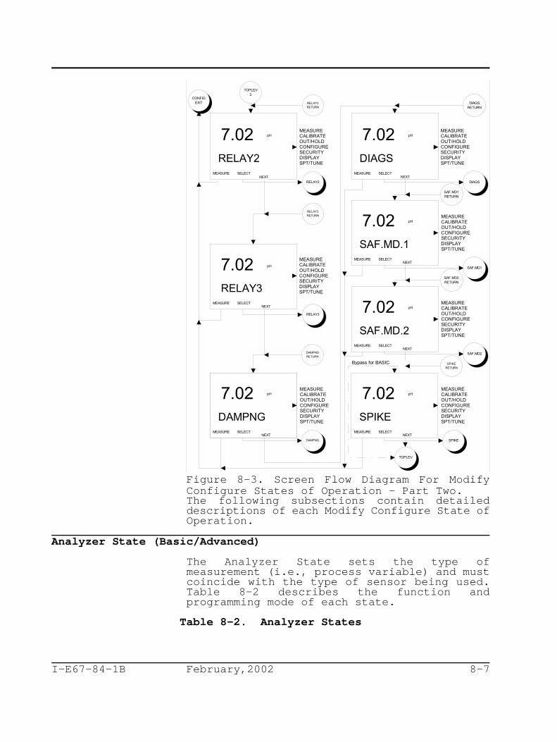
CONFIGEXIT
RELAY2
RELAY2
RELAY2RETURN
TOPLEV2
RELAY3
RELAY3RETURN
DAMPNG MEASURE SELECT
NEXT
DAMPNG
DAMPNGRETURN
SAF.MD.1MEASURE SELECT
NEXT
SPIKE MEASURE SELECT
NEXT
SAF.MD1
SPIKE
SPIKERETURN
SAF.MD1RETURN
pH7.02
pH7.02
pH7.02
MEASURECALIBRATEOUT/HOLDCONFIGURESECURITYDISPLAYSPT/TUNE
MEASURECALIBRATEOUT/HOLDCONFIGURESECURITYDISPLAYSPT/TUNE
MEASURECALIBRATEOUT/HOLDCONFIGURESECURITYDISPLAYSPT/TUNE
MEASURECALIBRATEOUT/HOLDCONFIGURESECURITYDISPLAYSPT/TUNE
MEASURECALIBRATEOUT/HOLDCONFIGURESECURITYDISPLAYSPT/TUNE
pH7.02
pH7.02
TOPLEV
RELAY3
SAF.MD.2 MEASURE SELECT
NEXTSAF.MD2
SAF.MD2RETURN
Bypass for BASIC
pH7.02 MEASURECALIBRATEOUT/HOLDCONFIGURESECURITYDISPLAYSPT/TUNE
MEASURE SELECT
NEXTMEASURE SELECT
DIAGS
NEXT
MEASURECALIBRATEOUT/HOLDCONFIGURESECURITYDISPLAYSPT/TUNE
pH7.02
MEASURE SELECT
DIAGS
NEXT
DIAGSRETURN
I-E67-84-1B February,2002 8-7
Figure 8-3. Screen Flow Diagram For ModifyConfigure States of Operation - Part Two.The following subsections contain detaileddescriptions of each Modify Configure State ofOperation.
Analyzer State (Basic/Advanced)
The Analyzer State sets the type ofmeasurement (i.e., process variable) and mustcoincide with the type of sensor being used.Table 8-2 describes the function andprogramming mode of each state.
Table 8-2. Analyzer States

I-E67-84-1B February,2002 8-8
State Function ProgrammingMode
PH Used to measure the pH of a solution. Basic/AdvancedProcess variable engineering units arepH.
ORP Used to measure the Oxidation Reduction Basic/AdvancedPotential (ORP) of a solution. Processvariable engineering units aremilliVolts (mV).
PION Used to measure the concentration of a Basic/Advancedspecific ion in a solution. The sensormust use a measurement electrodespecific to the ion of interest.Process variable engineering units aremilliVolts (mV).
ION.CON Used to measure the concentration of a Advancedspecific ion in a solution. The sensormust use a measurement electrodespecific to the ion of interest.Process variable engineering units areset by the user, and the output isdirectly proportional to those unitsand is established by the number ofconcentration decades.
pH Analyzer State (Basic/Advanced)
The pH Analyzer State contains three types ofsensors: Glass, Antimony, and Custom. Table8-3 describes the function and programmingmode of each state.
Table 8-3. pH Analyzer States
State Function ProgrammingMode
PH.GLAS Used when the associated sensor has a Basic/Advancedstandard glass measuring electrode.
ANTMNY Used when the associated sensor has an Basic/Advancedantimony measuring electrode.
CUSTOM Used when the associated sensor has a Advancedmeasuring electrode with a uniqueisopotential point and asymmetricpotential.
For Advanced configurations using the PH.GLASand ANTMNY Analyzer States, the REF Z (i.e.,reference impedance) value can be manually setto a new value or left at the default value of100 kohms. The REF Z is the referenceelectrode impedance value that will trigger adiagnostic condition. This value is set using

I-E67-84-1B February,2002 8-9
the Smart Key to increment and the SmartKey to move. The ENTER Smart Key accepts thenew value. See Section 13, Diagnostics, formore information on diagnostic reporting.
The reference impedance of a new ABB sensor istypically 1 to 2 kohms as measured by thediagnostic circuit of the TB84PH AdvantageSeries analyzer. Performance of the referenceelectrode is typically unaffected up to 100kohms (i.e., the default REF Z value).Adjustment to other resistance values up to1000 kohms is allowed; however, acceptableperformance of the sensor must be determinedby the user and the resistance valuesaccordantly adjusted.
For the CUSTOM State, the ISO.PT (i.e.,Isopotential pH value) and ASY.POT (i.e.,Asymmetric Potential value) must be enteredusing the Smart Key to increment theblinking digit, the Smart Key to move tothe next digit, and the ENTER Smart Key toenter the new value. The REF Z value can alsobe adjusted and must be set as previouslydescribed.
ORP and pION States (Basic/Advanced)
The ORP or pION Analyzer States are set bypressing the ENTER Smart Key on the desiredstate when displayed using the NEXT Smart Key.For Advanced configurations, the ORP and pIONStates will require the user to enter the REFZ value. The REF Z (i.e., referenceimpedance) is the reference electrodeimpedance value that will trigger a diagnosticcondition.

I-E67-84-1B February,2002 8-10
The REF Z value is set using the Smart Keyto increment the blinking digit, the SmartKey to move to the next digit, and the ENTERSmart Key to enter the new value. See Section13, Diagnostics, for more information ondiagnostic reporting.
Ion Concentration State (Advanced)
The ION.CON (i.e., Ion Concentration) Stateallows for pION sensor inputs to be convertedto concentration units such as ppb and ppm.This state uses temperature compensated mVvalues and applies a logarithmic function thathas a fixed end point in millivolts, an ionvalence ranging from -3 to +3, and an endpoint magnitude which can be set to 10, 100,or 1000.
The ION.CON State functions by associating anend millivolt value to an end magnitude value.The valence determines the millivolt changeper decade of concentration and is defined bythe Nernst Equation (i.e., 59.16 mV/decade fora valence equal to 1, 29.58 mV/decade for avalence equal to 2, and 19.72 mV/decade for avalence equal to 3). If the valence isnegative the millivolt/concentrationrelationship will have a negative slope. Thenumber of magnitudes defines the analyzeroutput. For example, two magnitudes would setthe output to 0-10% for the first magnitudeand 10-100% for the second magnitude.
Configure an ION.CON Analyzer State usingFigure 8-4 as a reference and the followingprocedure:
1) Enter the ION.CON State using the ENTERKey.
2) Set the engineering UNIT by toggling tothe desired unit using the NEXT Key andentering the unit using the ENTER Key.
3) Set the VALENC (i.e., valence) byincrementing or decrementing thedisplayed value using and Keysrespectively, and entering the new valueusing the ENTER Key.

UNIT MEASURE
NEXT
UNIT MEASURE
NEXTENTER
ENTER
IONCON
CONFIGEXIT
ppb
ppm
ENTER
VALENC MEASURE
-3
ENTER
END MV MEASURE
ENTER
END.MAG MEASURE
ENTER
MAGS MEASURE
2
100
-300
REF Z
mV
MEASURECALIBRATEOUT/HOLDCONFIGURESECURITYDISPLAYSPT/TUNE
MEASURECALIBRATEOUT/HOLDCONFIGURESECURITYDISPLAYSPT/TUNE
MEASURECALIBRATEOUT/HOLDCONFIGURESECURITYDISPLAYSPT/TUNE
MEASURECALIBRATEOUT/HOLDCONFIGURESECURITYDISPLAYSPT/TUNE
MEASURECALIBRATEOUT/HOLDCONFIGURESECURITYDISPLAYSPT/TUNE
MEASURECALIBRATEOUT/HOLDCONFIGURESECURITYDISPLAYSPT/TUNE
I-E67-84-1B February,2002 8-11
Figure 8-4. Screen Flows For Ion ConcentrationConfigure State of Operation.4) Set the MAGS (i.e., magnitudes) by
incrementing or decrementing thedisplayed value using and Keysrespectively, and entering the new valueusing the ENTER Key.
5) Set the END.MAG (i.e., ending magnitude)by incrementing or decrementing thedisplayed value using and Keysrespectively, and entering the new valueusing the ENTER Key.
6) Set the END MV (i.e., ending millivolt)by using the Key to increment theblinking digit and the Key to move tothe next digit and pressing the ENTER Key

I-E67-84-1B February,2002 8-12
to enter the new value.
7) Set the REFZ (i.e., reference impedance)by using the Key to increment theblinking digit and the Key to move tothe next digit and pressing the ENTER Keyto enter the new value.
Temperature Sensor State (Basic/Advanced)The Temperature Sensor State configures thetemperature input for a Pt100, 3 kohm Balco,or no (i.e., NONE) RTD.
Set the Temperature Sensor State using thefollowing procedure.
1) Select the TMP.SNS State using the SELECTKey.
2) Choose the desired temperature sensor byusing the NEXT Key to toggle betweenNONE, 3K.BLCO (i.e., 3 kohm Balco), andPT100, and enter the temperature sensorby using the ENTER Key when the correctsensor is displayed in the secondarydisplay.
Temperature Compensation State (Basic/Advanced)
Temperature affects the process variable intwo ways. The first effect (i.e., NernstianEffect) causes the sensor output to increasewith increasing temperature. In the case of apH sensor, the increase is roughly 0.03 pH/pHUnit From 7pH/10 C. Since ABB pH sensors useo
Silver/Silver Chloride Measurement andReference Half Cells, the isopotential point(i.e., the pH value that is unaffected bytemperature) of these sensors is 7 pH.
The second temperature effect is on the actualchemistry of the solution. Since iondisassociation can be a function oftemperature, ion properties such as pH, ORP,and pION are affected by changes in processtemperature. These effects can be empiricallydetermined and included in the temperaturecompensation process using the AutomaticNernstian with Solution CoefficientTemperature Compensation option.
The Temperature Compensation State sets thedesired compensating method. The three statesof temperature compensation include ManualNernstian, Automatic Nernstian, and AutomaticNernstian with Solution Coefficient. Table 8-

I-E67-84-1B February,2002 8-13
4 describes the function and programming modeof each state.
Table 8-4. Temperature Compensation States
State Function ProgrammingMode
MANUAL Used when a fixed temperature value Basic/Advancedcan be applied instead of a measuredvalue. The initial value is set at25 C. Use the Temperature Calibrateo
State to change the fixed temperaturevalue. Nernstian compensation isapplied using the fixed temperaturevalue.
AUTO Used when a measured temperature value Basic/Advancedis being provided by a temperaturesensor. Nernstian compensation isapplied using the measured value.
AUT.SOL Used when a measured temperature value Advancedis being provided by a temperaturesensor. Nernstian compensation and asolution coefficient is applied usingthe measured value.
Manual Nernstian State (Basic/Advanced)
Manual temperature compensation adjusts fortemperature effects of the sensor at aspecific temperature. A temperature sensor isnot required (i.e., NONE for TMP.SNS). TheManual Nernstian State is only applicable forpH Analyzer States. The displayed processvariable (i.e., pH) is standardized to 25 C.o

I-E67-84-1B February,2002 8-14
When using the Manual Nernstian State, theprocess temperature will be automatically setto 25 C. To adjust the temperature to othero
values, use the Temperature Calibrate Stateand set the temperature to the new value asspecified in Section 6, Calibrate Mode. Theallowable solution temperature range is 0 to140 C.o
Set the Temperature Compensation State toManual Nernstian State using the followingprocedure:
1) Select the TC.TYPE State using the SelectKey.
2) Move to the MANUAL Nernstian State usingthe Next Key.
3) Set the TC.TYPE to MANUAL using the EnterKey.
Automatic Nernstian State (Basic/Advanced)
Automatic Nernstian temperature compensationrequires an input from a temperature sensingdevice. The input can be either from a Pt100or 3 kohm Balco RTD.
Automatic Nernstian temperature compensationcorrects for temperature effects caused bysensor and is only applicable for the pHAnalyzer State. The displayed processvariable (i.e., pH) is standardized to 25 C,o
and the allowable solution temperature rangeis 0 to 140 C.o
Set the Temperature Compensation State toAutomatic Nernstian State using the followingprocedure:
1) Select the TC.TYPE State using the SelectKey.
2) Move to the AUTO Nernstian State usingthe Next Key.
3) Set the TC.TYPE to AUTO using the EnterKey.
Automatic Nernstian With Solution CoefficientState (Advanced)The Automatic Nernstian With SolutionCoefficient State compensates the sensoroutput to a reference temperature of 25 C usingo
the Nernst Equation and a solution


I-E67-84-1B February,2002 8-16
State using the NEXT Key.
3) Set the TC.TYPE to AUT.SOL using theENTER Key.
4) Set the PH/10C or MV/10C value (as thecase may be) using the Key toincrement the blinking digit and the Key to move to the next digit andpressing the ENTER Key to enter the newvalue.
Analog Output One State (Basic/Advanced)The Analog Output One State sets the outputspan, range, and function. The output span issoftware selectable for either zero to 20milliamperes or four to 20 milliamperes and issource to the Primary Process Variable. ForBasic configurations, the output function canonly be linear. Lower and upper range valuesmust be entered and are defaulted to the fullscale process variable range (e.g., 0-14 pHfor pH Analyzer States). For Advancedconfigurations, the output function can belinear or non-linear. For a non-linearoutput, lower and upper range values must alsobe entered as well as five break points.
Linear Output State (Basic/Advanced)
The Linear Output State establishes the lowerand upper range values. The default valuesfor the output represent the full scaleprocess variable range (e.g., 0-14 pH).
For a reverse acting output, reverse the zeroor four and 20 milliampere values (e.g., 14 pHfor the zero or four milliampere value and 0pH for the 20 milliampere value).

AO1.OUT
ENTER
4MA.PT MEASURE
ENTER
20MA.PT MEASURE
pH0.00
pH14.0
MEASURECALIBRATEOUT/HOLDCONFIGURESECURITYDISPLAYSPT/TUNE
MEASURECALIBRATEOUT/HOLDCONFIGURESECURITYDISPLAYSPT/TUNE
CONFIGEXIT
LINEAR MEASURE
NEXT
NON.LIN MEASURE
NEXT
pH7.02
pH7.02
ENTER
ENTER
MEASURECALIBRATEOUT/HOLDCONFIGURESECURITYDISPLAYSPT/TUNE
MEASURECALIBRATEOUT/HOLDCONFIGURESECURITYDISPLAYSPT/TUNE
NON.LIN
ENTER
4-20MA MEASURE
ENTER
0-20MA MEASURE
pH7.02
pH 7.02
MEASURECALIBRATEOUT/HOLDCONFIGURESECURITYDISPLAYSPT/TUNE
MEASURECALIBRATEOUT/HOLDCONFIGURESECURITYDISPLAYSPT/TUNE
NEXT
NEXT
Display either 0mA or 4 mA according to selected range.
Last Selected
AO1.OUTRETURN
For Advanced Configurations.
For BASIC Configurations.
Notes: 1) Values are from the previous configuration or rerange entries.
I-E67-84-1B February,2002 8-17
Figure 8-5. Screen Flow Diagram For AnalogOutput One Configure State of Operation.Set the Linear Output State using Figure 8-5as reference and the following procedure:
1) Select the AO1.OUT State using the SELECTKey.
2) Set the output span using the NEXT Key totoggle between 4-20MA and 0-20MA, andpress the ENTER Key to enter the newspan.
3) Set the process variable value for the 0or 4 milliampere point using the Key

I-E67-84-1B February,2002 8-18
to increment the blinking digit and the Key to move to the next digit, and
press the ENTER Key to enter the newvalue.
4) Set the process variable value for the 20milliampere point using the Key toincrement the blinking digit and the Key to move to the next digit, and pressthe ENTER Key to enter the new value.
5) Select the LINEAR Output State using theSELECT Key for Advanced configurations.For Basic configurations, this step willnot be accessible.
Non-Linear Output State (Advanced)The Non-Linear Output State sets the end pointand break point values for a non-linear outputfunction. The default values for the outputrepresent the full scale process variablerange (e.g.,0 to 14 or -1999 to +1999 mV) andthe break points are set for a linear output(e.g., 20% input equals 20% output).
To define the break point values, a plot ofthe process variable against the desiredoutput (or variable that represents the outputvalue) must be segmented into six linearregions that best fit the non-linearrelationship. The points where the linearregions intersect should fall on the non-linear function and represent the break pointsthat are entered into Non-Linear Output State.
As with the Linear Output State, the outputrange must be defined and will represent the0% input/0% output and 100% input/100% outputpoints. Since the 0% and 100% points aredefined by the output range, the break pointinformation (e.g., X-1/Y-1, X-2/Y-2, etc.values) should not include the 0% input/0%output and 100% input/100% output values andmust be entered as percentage of input rangeand output span. Also as with a linearoutput, a reverse acting non-linear output canbe implemented by reversing the zero or fourand 20 milliampere process variable and breakpoint values (e.g., 1999 mV for the 4milliampere value and -1999 mV for the 20milliampere value).
Set the Analog Output One Non-Linear Stateusing Figure 8-5 as a reference and thefollowing procedure:

I-E67-84-1B February,2002 8-19
1) Select the AO2.OUT State using the SELECTKey.
2) Set the output span using the NEXT Key totoggle between 4-20MA and 0-20MA, andpress the ENTER Key to enter the newspan.
3) Set the process variable value for thezero or four milliampere point using the Key to increment the blinking digit andthe Key to move to the next digit, andpress the ENTER Key to enter the newvalue.
4) Set the process variable value for the 20milliampere point using the Key toincrement the blinking digit and the Key to move to the next digit, and pressthe ENTER Key to enter the new value.
4) Select the NON.LIN Output State by usingthe NEXT Key to change the programmingstate from LINEAR to NON.LIN and usingthe SELECT Key to accept the NON.LINOutput State.
5) Set the input percentage for the firstbreak point (X-1) using the Key toincrement the blinking digit and the Key to move to the next digit, and pressthe ENTER Key to enter the new value.
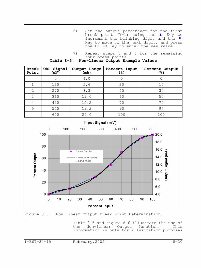
0
20
40
60
80
100
0 10 20 30 40 50 60 70 80 90 100
Pe rce nt Input
Per
cen
t O
utp
ut
4.0
6.0
8.0
10.0
12.0
14.0
16.0
18.0
20.0
0 100 200 300 400 500 600
Input Signal (m V)
Ou
tpu
t S
ign
al (
mA
)
B reak Points
A ctual N on-linearR elationship
I-E67-84-1B February,2002 8-20
6) Set the output percentage for the firstbreak point (Y-1) using the Key toincrement the blinking digit and the Key to move to the next digit, and pressthe ENTER Key to enter the new value.
7) Repeat steps 5 and 6 for the remainingfour break points.
Table 8-5. Non-linear Output Example Values
Break ORP Signal Output Range Percent Input Percent OutputPoint (mV) (mA) (%) (%)
0 4.0 0 0
1 120 5.6 20 10
2 270 8.8 45 30
3 360 12.0 60 50
4 420 15.2 70 70
5 540 19.2 90 95
600 20.0 100 100
Figure 8-6. Non-linear Output Break Point Determination.
Table 8-5 and Figure 8-6 illustrate the use ofthe Non-linear Output function. Thisinformation is only for illustration purposes

I-E67-84-1B February,2002 8-21
and does not characterize any specificapplication.
Analog Output Two State (Basic/Advanced)
The Analog Output Two State sets the outputsource, span, and range. The output can besourced to the Primary Process Variable orTemperature. As with Analog Output One, theoutput span is software selectable for eitherzero to 20 milliamperes or four to 20milliamperes. The output function is alwayslinear. Lower and upper range values must beentered and are defaulted to the full scaleprocess variable range (e.g., 0-14 pH for pHAnalyzer States).
Set the Analog Output Two State using Figure8-7 as reference and the following procedure:
1) Select the AO2.OUT State using the SELECTKey.
2) Set the output source using the NEXT Keyto toggle between PV and TEMP, and pressthe ENTER Key to enter the new source.
3) Set the output span using the NEXT Key totoggle between 4-20MA and 0-20MA, andpress the ENTER Key to enter the newspan.
4) Set the process variable value for the 0or 4 milliampere point using the Keyto increment the blinking digit and the Key to move to the next digit, and
press the ENTER Key to enter the newvalue.
5) Set the process variable value for the 20milliampere point using the Key toincrement the blinking digit and the Key to move to the next digit, and pressthe ENTER Key to enter the new value.

AO2.OUT
ENTERMEASURE
ENTERMEASURE
7.02
7.02
MEASURECALIBRATEOUT/HOLDCONFIGURESECURITYDISPLAYSPT/TUNE
MEASURECALIBRATEOUT/HOLDCONFIGURESECURITYDISPLAYSPT/TUNE
AO2.OUTRETURN
PV MEASURE
TEMP FMEASURE
ENTER
ENTER
pH7.02
pH7.02
MEASURECALIBRATEOUT/HOLDCONFIGURESECURITYDISPLAYSPT/TUNE
MEASURECALIBRATEOUT/HOLDCONFIGURESECURITYDISPLAYSPT/TUNE
TEMP CMEASURE
NEXTENTER
pH7.02 MEASURECALIBRATEOUT/HOLDCONFIGURESECURITYDISPLAYSPT/TUNE
NEXT
Last Selected
o
o 0-20MA
4-20MA
CONFIGEXIT
NEXT
ENTERMEASURE
100 MEASURECALIBRATEOUT/HOLDCONFIGURESECURITYDISPLAYSPT/TUNE
20MA.PT
ENTERMEASURE
25 MEASURECALIBRATEOUT/HOLDCONFIGURESECURITYDISPLAYSPT/TUNE
4MA.PT
NEXT
NEXT
Display either 0mA or 4mA according to selected range.
CO
CO
Last Selected
Last Selected
pH
pH
Bypass fo
r ION
.CO
N C
onfigura
tions
I-E67-84-1B February,2002 8-22
Figure 8-7. Screen Flow Diagram For AnalogOutput Two Configure State of Operation.
Relay Output One (Basic/Advanced)
The Relay Output One State sets the outputfunction and related parameters for RelayOutput One. The output function is dependenton the programming mode. For Basicconfigurations, Relay One output functions arelimited to Setpoint control of the ProcessVariable. For Advanced configurations, theoutput functions are not limited and can beconfigured as a Setpoint sourced to theProcess Variable or Temperature, Cycle Timer,Diagnostic, or Cleaner.
Set the output function of Relay Output OneState using Figure 8-8 as reference and the
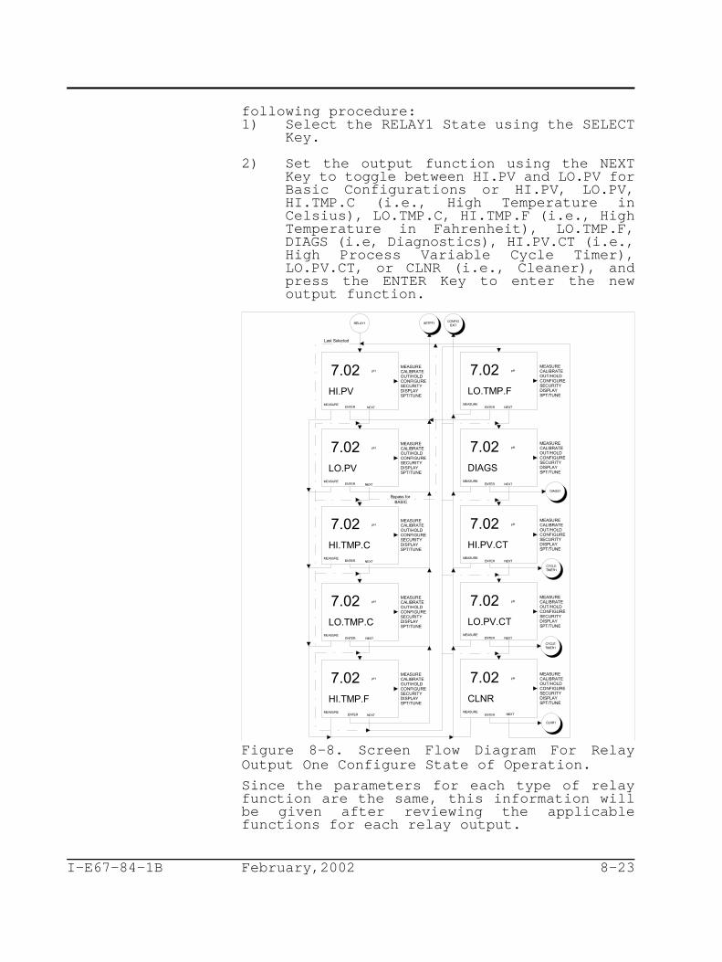
RELAY1CONFIG
EXIT
HI.PV MEASURE
NEXT
LO.PVMEASURE
HI.TMP.C MEASURE
LO.TMP.C MEASURE
HI.TMP.F MEASURE
NEXT
LO.TMP.F MEASURE
pH7.02
pH7.02
pH7.02
pH7.02
pH7.02
pH7.02
ENTER
SETPT1
ENTER
MEASURECALIBRATEOUT/HOLDCONFIGURESECURITYDISPLAYSPT/TUNE
MEASURECALIBRATEOUT/HOLDCONFIGURESECURITYDISPLAYSPT/TUNE
MEASURECALIBRATEOUT/HOLDCONFIGURESECURITYDISPLAYSPT/TUNE
MEASURECALIBRATEOUT/HOLDCONFIGURESECURITYDISPLAYSPT/TUNE
MEASURECALIBRATEOUT/HOLDCONFIGURESECURITYDISPLAYSPT/TUNE
MEASURECALIBRATEOUT/HOLDCONFIGURESECURITYDISPLAYSPT/TUNE
HI.PV.CTMEASURE
pH7.02
ENTER
MEASURECALIBRATEOUT/HOLDCONFIGURESECURITYDISPLAYSPT/TUNE
CYCLETIMER1
LO.PV.CTMEASURE
pH7.02
ENTER
MEASURECALIBRATEOUT/HOLDCONFIGURESECURITYDISPLAYSPT/TUNE
CYCLETIMER1
CLNR1
CLNR MEASURE
NEXT
pH7.02
ENTER
MEASURECALIBRATEOUT/HOLDCONFIGURESECURITYDISPLAYSPT/TUNE
ENTER
ENTER
ENTER
ENTER
DIAGS MEASURE
NEXT
pH7.02
ENTER
MEASURECALIBRATEOUT/HOLDCONFIGURESECURITYDISPLAYSPT/TUNE
DIAGS1
NEXT
NEXT
NEXT NEXT
NEXT NEXT
Last Selected
Bypass for BASIC
I-E67-84-1B February,2002 8-23
following procedure:1) Select the RELAY1 State using the SELECT
Key.
2) Set the output function using the NEXTKey to toggle between HI.PV and LO.PV forBasic Configurations or HI.PV, LO.PV,HI.TMP.C (i.e., High Temperature inCelsius), LO.TMP.C, HI.TMP.F (i.e., HighTemperature in Fahrenheit), LO.TMP.F,DIAGS (i.e, Diagnostics), HI.PV.CT (i.e.,High Process Variable Cycle Timer),LO.PV.CT, or CLNR (i.e., Cleaner), andpress the ENTER Key to enter the newoutput function.
Figure 8-8. Screen Flow Diagram For RelayOutput One Configure State of Operation.
Since the parameters for each type of relayfunction are the same, this information willbe given after reviewing the applicablefunctions for each relay output.

RELAY2CONFIG
EXIT
HI.PV MEASURE
NEXT
LO.PVMEASURE
HI.TMP.C MEASURE
LO.TMP.C MEASURE
HI.TMP.F MEASURE
NEXT
LO.TMP.F MEASURE
pH7.02
pH7.02
pH7.02
pH7.02
pH7.02
pH7.02
ENTER
SETPT2
ENTER
MEASURECALIBRATEOUT/HOLDCONFIGURESECURITYDISPLAYSPT/TUNE
MEASURECALIBRATEOUT/HOLDCONFIGURESECURITYDISPLAYSPT/TUNE
MEASURECALIBRATEOUT/HOLDCONFIGURESECURITYDISPLAYSPT/TUNE
MEASURECALIBRATEOUT/HOLDCONFIGURESECURITYDISPLAYSPT/TUNE
MEASURECALIBRATEOUT/HOLDCONFIGURESECURITYDISPLAYSPT/TUNE
MEASURECALIBRATEOUT/HOLDCONFIGURESECURITYDISPLAYSPT/TUNE
HI.PV.CTMEASURE
pH7.02
ENTER
MEASURECALIBRATEOUT/HOLDCONFIGURESECURITYDISPLAYSPT/TUNE
CYCLETIMER2
LO.PV.CTMEASURE
pH7.02
ENTER
MEASURECALIBRATEOUT/HOLDCONFIGURESECURITYDISPLAYSPT/TUNE
CYCLETIMER2
CLNR2
CLNR MEASURE
NEXT
pH7.02
ENTER
MEASURECALIBRATEOUT/HOLDCONFIGURESECURITYDISPLAYSPT/TUNE
ENTER
ENTER
ENTER
ENTER
DIAGS MEASURE
NEXT
pH7.02
ENTER
MEASURECALIBRATEOUT/HOLDCONFIGURESECURITYDISPLAYSPT/TUNE
DIAGS2
NEXT
NEXT
NEXT NEXT
NEXT NEXT
Last Selected
Bypass for BASIC
I-E67-84-1B February,2002 8-24
Relay Output Two (Basic/Advanced)
The Relay Output Two State sets the outputfunction and related parameters for RelayOutput Two. The output function is dependenton the programming mode. For Basicconfigurations, Relay Two output functions arelimited to Setpoint control of the ProcessVariable and Temperature. For Advancedconfigurations, the output functions are notlimited and can be configured as a Setpointsourced to the Process Variable orTemperature, Cycle Timer, Diagnostic, orCleaner.
Figure 8-9. Screen Flow Diagram For RelayOutput Two Configure State of Operation.Set the output function of Relay Output TwoState using Figure 8-9 as reference and thefollowing procedure:
1) Select the RELAY2 State using the SELECTKey.
2) Set the output function using the NEXTKey to toggle between HI.PV, LO.PV,

I-E67-84-1B February,2002 8-25
HI.TMP.C, LO.TMP.C, HI.TMP.F, andLO.TMP.F for Basic Configurations orHI.PV, LO.PV, HI.TMP.C, LO.TMP.C,HI.TMP.F, LO.TMP.F, DIAGS, HI.PV.CT,LO.PV.CT, or CLNR, and press the ENTERKey to enter the new function.
Since the parameters for each type of relayfunction are the same, this information willbe given after reviewing the applicablefunctions for each relay output.
Relay Output Three (Basic/Advanced)
The Relay Output Three State sets the outputfunction and parameters for Relay OutputThree. The output function is dependent onthe programming mode. For Basicconfigurations, Relay Three output functionsare limited to Setpoint control of the ProcessVariable and Temperature and Diagnosticnotification. For Advanced configurations,the output functions are not limited and canbe configured as a Setpoint sourced to theProcess Variable or Temperature, Cycle Timer,Diagnostic, or Cleaner.
Set the output function of Relay Output ThreeState using Figure 8-10 as reference and thefollowing procedure:
1) Select the RELAY3 State using the SELECTKey.
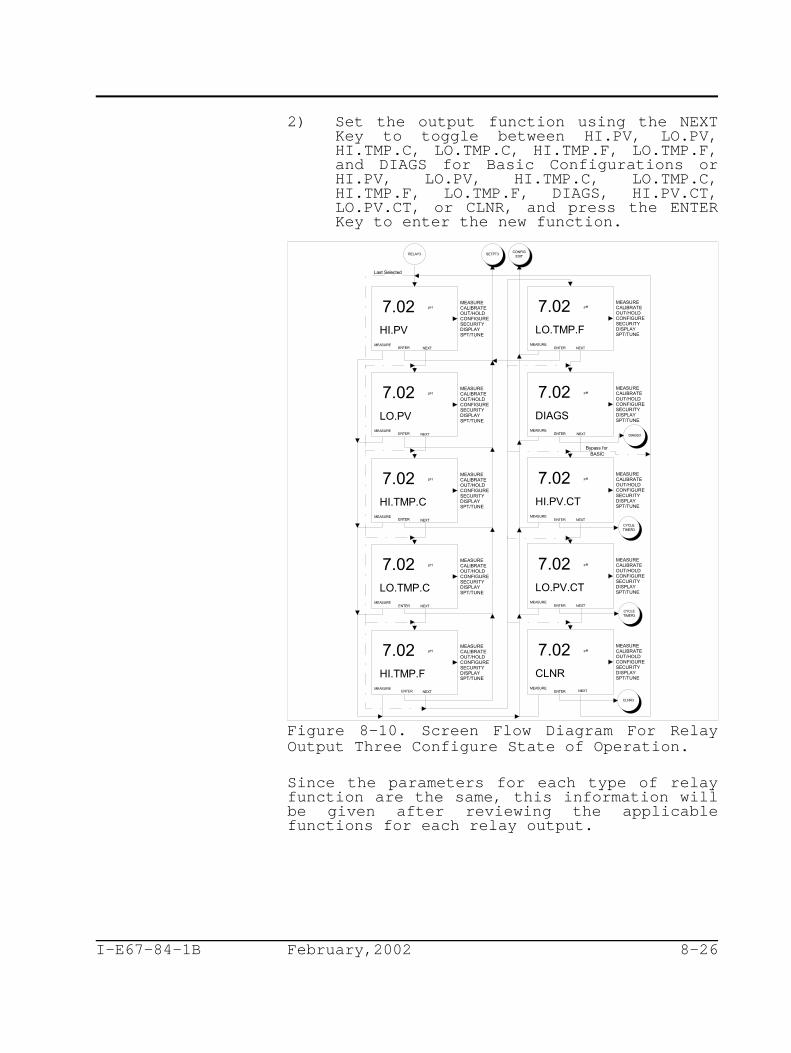
RELAY3CONFIG
EXIT
HI.PV MEASURE
NEXT
LO.PVMEASURE
HI.TMP.C MEASURE
LO.TMP.C MEASURE
HI.TMP.F MEASURE
NEXT
LO.TMP.F MEASURE
pH7.02
pH7.02
pH7.02
pH7.02
pH7.02
pH7.02
ENTER
SETPT3
ENTER
MEASURECALIBRATEOUT/HOLDCONFIGURESECURITYDISPLAYSPT/TUNE
MEASURECALIBRATEOUT/HOLDCONFIGURESECURITYDISPLAYSPT/TUNE
MEASURECALIBRATEOUT/HOLDCONFIGURESECURITYDISPLAYSPT/TUNE
MEASURECALIBRATEOUT/HOLDCONFIGURESECURITYDISPLAYSPT/TUNE
MEASURECALIBRATEOUT/HOLDCONFIGURESECURITYDISPLAYSPT/TUNE
MEASURECALIBRATEOUT/HOLDCONFIGURESECURITYDISPLAYSPT/TUNE
HI.PV.CTMEASURE
pH7.02
ENTER
MEASURECALIBRATEOUT/HOLDCONFIGURESECURITYDISPLAYSPT/TUNE
CYCLETIMER3
LO.PV.CTMEASURE
pH7.02
ENTER
MEASURECALIBRATEOUT/HOLDCONFIGURESECURITYDISPLAYSPT/TUNE
CYCLETIMER3
CLNR3
CLNR MEASURE
NEXT
pH7.02
ENTER
MEASURECALIBRATEOUT/HOLDCONFIGURESECURITYDISPLAYSPT/TUNE
ENTER
ENTER
ENTER
ENTER
DIAGS MEASURE
NEXT
pH7.02
ENTER
MEASURECALIBRATEOUT/HOLDCONFIGURESECURITYDISPLAYSPT/TUNE
DIAGS3
NEXT
NEXT
NEXT NEXT
NEXT NEXT
Bypass for BASIC
Last Selected
I-E67-84-1B February,2002 8-26
2) Set the output function using the NEXTKey to toggle between HI.PV, LO.PV,HI.TMP.C, LO.TMP.C, HI.TMP.F, LO.TMP.F,and DIAGS for Basic Configurations orHI.PV, LO.PV, HI.TMP.C, LO.TMP.C,HI.TMP.F, LO.TMP.F, DIAGS, HI.PV.CT,LO.PV.CT, or CLNR, and press the ENTERKey to enter the new function.
Figure 8-10. Screen Flow Diagram For RelayOutput Three Configure State of Operation.
Since the parameters for each type of relayfunction are the same, this information willbe given after reviewing the applicablefunctions for each relay output.

I-E67-84-1B February,2002 8-27
Setpoint Relay Output (Basic/Advanced)
A Setpoint Relay Output can be configured toenergize when the Process Variable orTemperature exceeds (i.e., a High Setpoint) orfalls below (i.e., a Low Setpoint) a definedlevel. Valid Setpoint values are limited tothe Process Variable and/or Temperature rangeof the TB84PH Advantage Series analyzer. SeeTable 1-3, Specifications, for analyzer rangevalues.
To prevent relay chatter, a Setpoint RelayOutput has an configurable Deadband. TheDeadband control keeps the relay energizeduntil the Process Variable or Temperature hasdecreased below a High Setpoint value or abovea Low Setpoint value by the Deadband value.Valid Deadband values are 0.00 to 10.00 pH forpH, 0 to 200 mV for ORP and pION, 0 to 10% ofthe END.MAG (i.e., End Magnitude) for IonConcentration Process Variable sources and 0to 10 C (18 F) for Temperature sources.o o
A Time Delay control also refines the functionof a Setpoint Relay. Entering a Time Delayvalue greater than 0.0 minutes enables awaiting period before energizing the relayonce the setpoint condition has been met.Valid Time Delay values are 0.0 to 99.9minutes.
Set the Setpoint parameters of a Relay Outputusing Figure 8-11 as reference and thefollowing procedure:
1) Set the Setpoint (i.e., LO SPT or HI SPT)using the Key to increment theblinking digit and the Key to move tothe next digit, and press the ENTER Keyto enter the new value.
2) Set the Deadband (i.e., DBAND) using the Key to increment the blinking digit andthe Key to move to the next digit and,press the ENTER Key to enter the newvalue.

SETPT1
10.0
ENTER
HI SPTMEASURE
CONFIGEXIT
RELAY1RETURN
ENTER
DBANDMEASURE
0.0
ENTER
DLY.MINMEASURE
MEASURECALIBRATEOUT/HOLDCONFIGURESECURITYDISPLAYSPT/TUNE
MEASURECALIBRATEOUT/HOLDCONFIGURESECURITYDISPLAYSPT/TUNE
MEASURECALIBRATEOUT/HOLDCONFIGURESECURITYDISPLAYSPT/TUNE
Display "HI" or "LO",as configured.
pH
0.50 pH
*
* 99.9 minutes is the maximum allowable time limit.
Display units and PV as configured.
I-E67-84-1B February,2002 8-28
3) Set the Time Delay in minutes (i.e.,DLY.MIN) using the Key to incrementthe blinking digit and the Key to moveto the next digit, and press the ENTERKey to enter the new value.
Figure 8-11. Screen Flow Diagram For Settingthe Setpoint Relay Output Configure State ofOperation.
Diagnostic Relay Output (Basic/Advanced)
A Diagnostic Relay Output simply energizeswhen a diagnostic condition has be detected.The relay can be configured to trigger on asensor, instrument, or all diagnosticconditions.

DIAGS1
ALL MEASURE
INSTR.MEASURE
NEXT
ENTER
ENTER
CONFIGEXIT
pH7.02
pH7.02
MEASURECALIBRATEOUT/HOLDCONFIGURESECURITYDISPLAYSPT/TUNE
MEASURECALIBRATEOUT/HOLDCONFIGURESECURITYDISPLAYSPT/TUNE
SENSORMEASURE
NEXTENTER
pH7.02 MEASURECALIBRATEOUT/HOLDCONFIGURESECURITYDISPLAYSPT/TUNE
NEXT
Last selected
RELAY1RETURN
NEXT
I-E67-84-1B February,2002 8-29
Set the trigger for the Diagnostic RelayOutput using Figure 8-12 as reference and thefollowing procedure:
1) Set the Diagnostic trigger using the NEXTKey to toggle between ALL, SENSOR, andINSTR. (i.e., Instrument), and press theENTER Key to enter the new trigger.
Figure 8-12. Screen Flow Diagram For Settingthe Diagnostic Relay Output Configure State ofOperation.
Cycle Timer Relay Output (Advanced)
A Cycle Timer can only be sourced to theProcess Variable and can energize the relayfor either a High or Low setpoint condition.
As with a Setpoint Relay Output, the Setpointcondition functions in the same manner;however, the Deadband control is replaced with

CYCLETIMER1
10.0
ENTER
LO SPTMEASURE
CONFIGEXIT
RELAY1RETURN
ENTER
CYC.MINMEASURE
0.5
ENTER
ON.MINMEASURE
MEASURECALIBRATEOUT/HOLDCONFIGURESECURITYDISPLAYSPT/TUNE
MEASURECALIBRATEOUT/HOLDCONFIGURESECURITYDISPLAYSPT/TUNE
MEASURECALIBRATEOUT/HOLDCONFIGURESECURITYDISPLAYSPT/TUNE
Display "HI" or "LO",as configured.
pH
1.0
*99.9 minutes is the maximum allowable time limit.
*
*
I-E67-84-1B February,2002 8-30
the Cycle Time. Thus, a Cycle Timer willenergize the Relay Output for a set amount oftime (ON.TIME) and de-energize for theremainder of the cycle (CYC.MIN). This cyclerepeats until the Setpoint condition is nolonger met. For more information on the CycleTimer, see Section 2, Overview.
Valid Setpoint values are limited to theProcess Variable range of the TB84PH AdvantageSeries analyzer. See Table 1-3,Specifications, for analyzer range values.Valid Cycle Time and On Time values are 0.0 to99.9 minutes.
Figure 8-13. Screen Flow Diagram For Settingthe Cycle Timer Relay Output Configure Stateof Operation.Set the Cycle Timer parameters of a RelayOutput using Figure 8-13 as reference and thefollowing procedure:
1) Set the Setpoint (i.e., LO SPT or HI SPT)using the Key to increment theblinking digit and the Key to move to

I-E67-84-1B February,2002 8-31
the next digit, and press the ENTER Keyto enter the new value.
2) Set the Cycle Time in minutes (i.e.,CYC.MIN) using the Key to incrementthe blinking digit and the Key to moveto the next digit, and press the ENTERKey to enter the new value.
3) Set the On Time in minutes (i.e., ON.MIN)using the Key to increment theblinking digit and the Key to move tothe next digit, and press the ENTER Keyto enter the new value.
Cleaner Relay Output (Advanced)
Automatic sensor cleaning can be accomplishedusing any one of the three relay outputs. Ata prescribed time interval, a Cleaner RelayOutput will energize and allow the activationof a cleaning device. While in the energizedstate, analog and relay outputs can be held tovalues captured just prior to the cleaningcycle (i.e., energized state). If a relayhold condition is not feasible, non-cleanerrelay outputs can be disable during a cleaningcycle.
To specify a cleaning cycle, the Cycle, On,and Recovery Times must be defined. The CycleTime defines the repeating period betweencleaning cycles, the On Time defines thelength of time the relay will be energized,and the Recovery Time defines the length oftime after the relay has been de-energizedbefore the hold and/or disable condition(s)will be removed. Valid times for Cycle Timeare 0.0 to 99.9 hours and for On and RecoveryTimes are 0.0 to 99.9 minutes.

I-E67-84-1B February,2002 8-32
Set the Cleaner parameters of a Relay Outputusing Figure 8-14 as reference and thefollowing procedure:
1) Set the Cycle Time in hours (i.e.,CYC.HRS) using the Key to incrementthe blinking digit and the Key to moveto the next digit, and press the ENTERKey to enter the new value.
2) Set the On Time in minutes (i.e., ON.MIN)using the Key to increment theblinking digit and the Key to move tothe next digit, and press the ENTER Keyto enter the new value.
3) Set the Recovery Time in minutes (i.e.,RCV.MIN) using the Key to incrementthe blinking digit and the Key to moveto the next digit, and press the ENTERKey to enter the new value.
4) Hold the Analog Outputs (i.e., AO.HLD)during the On and Recovery Times usingthe YES Key, or leave the Analog Outputslive during the On and Recovery Timesusing the No Key.
5) Hold the Relay Outputs (i.e., RO.HLD)during the On and Recovery Times usingthe YES Key, or continue onto the DisableRelay Outputs State during the On andRecovery Times using the No Key.
6) Disable the Relay Outputs (i.e., RO.HLD)during the On and Recovery Times usingthe YES Key, or leave the Relay Outputslive during the On and Recovery Timesusing the No Key.
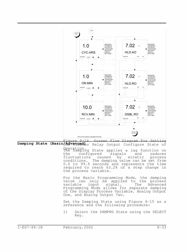
CLNR1
1.0CYC.HRS
MEASURE
1.0ON.MIN
MEASURE
10.0RCV.MIN
MEASURE
CONFIGEXIT
ENTER
ENTER
ENTER
RELAY1RETURN
MEASURECALIBRATEOUT/HOLDCONFIGURESECURITYDISPLAYSPT/TUNE
MEASURECALIBRATEOUT/HOLDCONFIGURESECURITYDISPLAYSPT/TUNE
MEASURECALIBRATEOUT/HOLDCONFIGURESECURITYDISPLAYSPT/TUNE
NO
MEASURE YES
HLD.AO
pH7.02 MEASURECALIBRATEOUT/HOLDCONFIGURESECURITYDISPLAYSPT/TUNE
*
* 99.9 is the maximum allowable time limit.
*
*
HLD.ROMEASURE
MEASURECALIBRATEOUT/HOLDCONFIGURESECURITYDISPLAYSPT/TUNE
DSBL.ROMEASURE
MEASURECALIBRATEOUT/HOLDCONFIGURESECURITYDISPLAYSPT/TUNE
NOYES
NOYES
7.02 pH
7.02 pH
I-E67-84-1B February,2002 8-33
Figure 8-14. Screen Flow Diagram For Settingthe Cleaner Relay Output Configure State ofOperation.
Damping State (Basic/Advanced)
The Damping State applies a lag function onthe configured signals and reducesfluctuations caused by erratic processconditions. The damping value can be set from0.0 to 99.9 seconds and represents the timerequired to reach 63.2% of a step change inthe process variable.
For the Basic Programming Mode, the dampingvalue can only be applied to the processvariable input signal. The AdvancedProgramming Mode allows for separate dampingof the Display Process Variable, Analog OutputOne, and Analog Output Two.
Set the Damping State using Figure 8-15 as areference and the following procedure:
1) Select the DAMPNG State using the SELECTKey.

DAMPNG
0.0
ENTER
SECS MEASURE
DAMPNGRETURN
CONFIGEXIT
MEASURECALIBRATEOUT/HOLDCONFIGURESECURITYDISPLAYSPT/TUNE
0.0
ENTER
DSP.SEC MEASURE
MEASURECALIBRATEOUT/HOLDCONFIGURESECURITYDISPLAYSPT/TUNE
0.0
ENTER
A01.SEC MEASURE
MEASURECALIBRATEOUT/HOLDCONFIGURESECURITYDISPLAYSPT/TUNE
0.0
ENTER
AO2.SEC MEASURE
MEASURECALIBRATEOUT/HOLDCONFIGURESECURITYDISPLAYSPT/TUNE
ADVANCED Configuration Only.BASIC Configuration Only.
I-E67-84-1B February,2002 8-34
2) For Basic configurations, set the newdamping value using the Key toincrement the blinking digit and the Key to move to the next digit, and pressthe ENTER Key to enter the new value.
3) For Advanced configurations, set the newdamping value for the Displayed ProcessVariable (i.e., DSP.SEC) using the Keyto increment the blinking digit and the Key to move to the next digit, and
press the ENTER Key to enter the newvalue.
Figure 8-15. Screen Flow Diagram For DampingConfigure State of Operation.4) For Advanced configurations, set the new
damping value for Analog Output One(i.e., AO1.SEC) using the Key toincrement the blinking digit and the Key to move to the next digit, and pressthe ENTER Key to enter the new value.
5) For Advanced configurations, set the newdamping value for Analog Output Two

I-E67-84-1B February,2002 8-35
(i.e., AO2.SEC) using the Key toincrement the blinking digit and the Key to move to the next digit, and pressthe ENTER Key to enter the new value.
Diagnostics State (Basic/Advanced)
The Diagnostics State allows the built-insensor diagnostics to be disabled. When asensor does not have a solution ground such asNon-Advantage (i.e., TB5) sensors, thediagnostic signal cannot be injected intoprocess liquid. For these situations andapplications that use very pure water, thesensor diagnostics should be disabled.
Set the DIAG (i.e., Diagnostics) State usingthe following procedure:
1) Select the DIAG State using the SELECTKey.
2) Toggle the diagnostics function to thedesired state (i.e., OFF or ON) using the Key, and press the ENTER Key to enter
the new value.
Safe Mode One State (Basic/Advanced)
The Safe Mode One State determines the AnalogOutput One level if an error condition occursthat renders the analyzer inoperable. Theavailable states are FAIL.LO (i.e., fail low)or FAIL.HI (i.e., fail high). For moreinformation on error conditions, see Section13, Diagnostics.
Set the Safe Mode One State using thefollowing procedure:
1) Select the SAF.MD.1 State using theSELECT Key.
2) Set the safe mode by using the NEXT Keyto toggle between FAIL.LO and FAIL.HI,and use the ENTER Key to enter the newvalue.
Safe Mode Two State (Basic/Advanced)
The Safe Mode Two State determines the AnalogOutput Two level if an error condition occursthat renders the analyzer inoperable. Theavailable states are FAIL.LO (i.e., fail low)and FAIL.HI (i.e., fail high). For moreinformation on error conditions, see Section

I-E67-84-1B February,2002 8-36
13, Diagnostics.
Set the Safe Mode Two State using thefollowing procedure:
1) Select the SAF.MD.2 State using theSELECT Key.
2) Set the safe mode by using the NEXT Keyto toggle between FAIL.LO and FAIL.HI,and use the ENTER Key to enter the newvalue.
Spike State (Advanced)
The Spike State sets the diagnostic spikelevel as a percent of output. This level willdetermine the magnitude of the spike.
When the Spike has been set for any levelgreater than 0% and is enabled in the SpikeOutput State, the TB84PH Advantage Seriesanalyzer will modulate the Analog Output Onesignal by the configured level for one secondout of every six seconds when a problemcondition is detected. Using this modulation,the analyzer informs the operator of adetected diagnostic condition. For moreinformation on problem conditions, see Section13, Diagnostics. For a description of thediagnostic spike feature, see Section 2,Analyzer Functionality And Operator InterfaceControls.
Set the Spike State using the followingprocedure:
1) Select the SPIKE State using the SELECTKey.
2) Set the SPK.MAG (i.e., spike magnitude)using the Key to increment theblinking digit and the Key to move tothe next digit, and press the ENTER Keyto enter the new value. The SpikeMagnitude is entered as a percentage ofthe 16 milliampere output range for afour to 20 milliampere output or 20milliampere output range for a zero to 20milliampere output (e.g., 10% willgenerate a 1.6 milliampere spike for afour to 20 milliampere output range).
Note: Once the Spike State is OFF, changing theconfigured spike level in the Configure Modewill not reenable the Spike State. The SpikeState can only be turned ON or OFF in the

FRONT BEZEL ASSEMBLY W/MICROPROCESSOR/DISPLAY PCB ASSEMBLY
REAR VIEW SHOWN
(Factory Default Setting)
I-E67-84-1B February,2002 8-37
Output/Hold Mode of Operation.
CONFIGURATION LOCKOUT
The TB84PH Advantage Series analyzer has alockout feature that, once engaged, prohibitsaccess to the Configure Mode. This featuredoes not affect parameters that can be changedin the other modes of operation includingCalibrate, Output/Hold, Security, secondaryDisplay, and Setpoint/Tune.
To enable the lockout feature, change jumperW1 on the Microprocessor/Display PCB from pins1 and 2 (i.e., position A - the factorydefault position) to pins 2 and 3 (i.e.,position B). Use Figure 8-16 and Section 16,Replacement Procedures, for jumper positionsand circuit board handling procedures.
Figure 8-16. Configuration Lockout Jumper Location OnMicroprocessor/Display PCB Assembly.
I-E67-84-1B February,2002 9-1
SECTION 9 - SECURITY MODE
INTRODUCTION
The Security Mode of Operation establishespassword protection against unauthorizedchanges to analyzer functions by unqualifiedpersonnel. Password protection can beassigned to the Calibrate, Output/Hold,Setpoint/Tune and Configure Modes ofOperation.
SECURITY STATE OF OPERATION
The Security Mode of Operation providespassword protection of critical operatingenvironments. Each mode or state of operationthat can be password protected is set bytoggling the primary display between securityOFF and ON using the Smart Key. As seen inFigure 9-1, all security assignments must bemade before a password can be defined.
When one or more mode(s)/state has thesecurity ON, the Security State will also besecured. One password assignment applies toall secured modes and states.
Set the Security State using Figure 9-1 as areference and the following procedure:
1) Select the SECUR (i.e., Security) Mode ofOperation using the SELECT Key.
2) Set the security for the CALIBR (i.e.,Calibrate) Mode using the Key totoggle between ON and OFF, and press theENTER Key to enter the new value.
3) Set the security for the OUTPUT (i.e.,Output/Hold) Mode using the Key totoggle between ON and OFF, and press theENTER Key to enter the new value.
4) Set the security for the CONFIG (i.e.,Modify Configure) State using the Keyto toggle between ON and OFF, and pressthe ENTER Key to enter the new value.

MEASURE
PASSWD
SECUR
OFFCALIBR
MEASUREENTER
ONCALIBR
MEASUREENTER
OFFOUTPUT
MEASUREENTER
ONOUTPUT
MEASUREENTER
OFFCONFIG
MEASUREENTER
ONCONFIG
MEASUREENTER
Bypass if no items arepassword protected.
Last selected
Last selected
OFFSPT.TUN
MEASUREENTER
ONSPT.TUN
MEASUREENTER
PASSWD2
MEASURECALIBRATEOUT/HOLDCONFIGURESECURITYDISPLAYSPT/TUNE
MEASURECALIBRATEOUT/HOLDCONFIGURESECURITYDISPLAYSPT/TUNE
MEASURECALIBRATEOUT/HOLDCONFIGURESECURITYDISPLAYSPT/TUNE
MEASURECALIBRATEOUT/HOLDCONFIGURESECURITYDISPLAYSPT/TUNE
MEASURECALIBRATEOUT/HOLDCONFIGURESECURITYDISPLAYSPT/TUNE
MEASURECALIBRATEOUT/HOLDCONFIGURESECURITYDISPLAYSPT/TUNE
MEASURECALIBRATEOUT/HOLDCONFIGURESECURITYDISPLAYSPT/TUNE
MEASURECALIBRATEOUT/HOLDCONFIGURESECURITYDISPLAYSPT/TUNE
Last selected
Last selected
I-E67-84-1B February,2002 9-2
Figure 9-1. Screen Flow Diagram For SecurityState of Operation.5) Set the security for the SPT.TUN (i.e.,
Setpoint/Tune) Mode using the Key totoggle between ON and OFF, and press theENTER Key to enter the new value.

I-E67-84-1B February,2002 9-3
6) Define the password for all secured modesand states using the Key to incrementthe blinking digit and the Key to moveto the next digit, and press the ENTERKey to enter the password.
Note: The password must be defined as threedigits and verified to enable security on themodes/states entered in steps 2 through 4. Ifsecurity is not ON for any of the modes/states,the password state will be bypassed.
6) Verify the password using the Key toincrement the blinking digit and the Key to move to the next digit, and pressthe ENTER Key to enter the password.
Remove all security using the followingprocedure:
1) Select the SECUR Mode of Operation usingthe SELECT Key.
2) Enter the password for all secured modesand states using the Key to incrementthe blinking digit and the Key to moveto the next digit, and press the ENTERKey to submit the password.
3) Set the security for the CALIBR (i.e.,Calibrate) Mode by pressing the Key totoggle the display to OFF, and press theENTER Key to enter the value.
4) Set the security for the OUTPUT (i.e.,Output/Hold) Mode by pressing the Keyto toggle the display to OFF, and pressthe ENTER Key to enter the value.
5) Set the security for the CONFIG (i.e.,Modify Configure) State by pressing the Key to toggle the display to OFF, and
press the ENTER Key to enter the value.
6) Set the security for the SPT.TUN (i.e.,Setpoint/Tune) Mode by pressing the Key to toggle the display to OFF, andpress the ENTER Key to enter the value.

I-E67-84-1B February,2002 9-4
Change the password or security state usingthe following procedure:
1) Select the SECUR Mode of Operation usingthe SELECT Key.
2) Enter the password for all secured modesand states using the Key to incrementthe blinking digit and the Key to moveto the next digit, and press the ENTERKey to submit the password.
3) Leave the security state unchanged forCALIBR (i.e., Calibrate) Mode by usingthe ENTER Key Set, or if needed, changethe security state for CALIBR (i.e.,Calibrate) using the Key. Press theENTER Key to enter the new value.
4) Leave the security state unchanged forOUTPUT (i.e., Output/Hold) Mode by usingthe ENTER Key Set, or if needed, changethe security state for OUTPUT using the Key. Press the ENTER Key to enter the
new value.
5) Leave the security state unchanged forCONFIG (i.e., Modify Configure) State byusing the ENTER Key Set, or if needed,change the security state for CONFIG(i.e., Modify Configure) using the Key. Press the ENTER Key to enter thenew value.
6) Leave the security state unchanged forSPT.TUN (i.e., Setpoint/Tune) Mode byusing the ENTER Key Set, or if needed,change the security state for SPT.TUN(i.e., Setpoint/Tune) using the Key.Press the ENTER Key to enter the newvalue.
7) Change the password for all secured modesand states using the Key to incrementthe blinking digit and the Key to moveto the next digit, and press the ENTERKey to enter the password.

I-E67-84-1B February,2002 9-5
8) Verify the new password using the Keyto increment the blinking digit and the Key to move to the next digit, and
press the ENTER Key to enter thepassword.
Note: If the password was not changed, theverification of the old password will not berequired.
If the password is lost, the security can beremoved using the Reset Password State ofOperation. To reset the password, see Section11, Utility Mode.

I-E67-84-1B February,2002 9-6

I-E67-84-1B February,2002 10-1
SECTION 10 - SECONDARY DISPLAY MODE
INTRODUCTION
The TB84PH Advantage Series analyzer has twodisplay regions. In the Measure Mode ofOperation, the primary display region showsthe measured process variable, and thesecondary display region can show a multitudeof process, sensor, or analyzer information.This information can be viewed or set as thedisplayed value when in the Measure Mode ofOperation.
SECONDARY DISPLAY STATE OF OPERATION
The Secondary Display Mode of Operationcontains seven states of operation thatprovide information on the processtemperature, output current values, sensoroutput, software revision, and spike status.As seen in Figure 10-1, each Secondary DisplayState can be sequentially viewed by using theNEXT Smart Key. To have any given SecondaryDisplay State be continually shown in theMeasure Mode, press the ENTER Smart Key whilethe desired state is displayed. The TB84PHAdvantage Series analyzer will proceed to theMeasure Mode and display the entered SecondaryDisplay State in the secondary display region.

SEC.DSPJump to last selected, may beany of the following screens.
MEASURENEXTENTER
6.0MA2 MEASURE
NEXTENTER
100KRZ MEASURE
NEXTENTER
-300MV MEASURE
NEXTENTER
REV.A10 MEASURE
NEXTENTER
74 F
MEASURENEXTENTER
MEASURE
pH7.02
pH7.02
pH7.027.02
pH7.02 pH7.02
pH7.02 MEASURECALIBRATEOUT/HOLDCONFIGURESECURITYDISPLAYSPT/TUNE
MEASURECALIBRATEOUT/HOLDCONFIGURESECURITYDISPLAYSPT/TUNE
MEASURECALIBRATEOUT/HOLDCONFIGURESECURITYDISPLAYSPT/TUNE
MEASURECALIBRATEOUT/HOLDCONFIGURESECURITYDISPLAYSPT/TUNE
MEASURECALIBRATEOUT/HOLDCONFIGURESECURITYDISPLAYSPT/TUNE
MEASURECALIBRATEOUT/HOLDCONFIGURESECURITYDISPLAYSPT/TUNE
Mo
23 C Mo
"M" indicates manualtemp compensation.
12.0MA1 MEASURE
NEXTENTER
pH7.027.02 MEASURECALIBRATEOUT/HOLDCONFIGURESECURITYDISPLAYSPT/TUNE
I-E67-84-1B February,2002 10-2
Figure 10-1. Screen Flow Diagram For SecondaryDisplay States of Operation.
I-E67-84-1B February,2002 11-1
SECTION 11 - SETPOINT/TUNE MODE
INTRODUCTION
The Setpoint/Tune Mode of Operation provides adirect method to tune relay output parameters.Though this mode of operation can not be usedto change the function a relay, it doesprovide the ability to change relay parameterspertinent to process control. To change therelay output function, see Section 8,Configure Mode.
SETPOINT/TUNE STATES OF OPERATION
The Setpoint/Tune Mode consists of threestates of operation: RELAY1, RELAY2, andRELAY3. Each state provides the ability toupdate operational parameters for theconfigured relay functions. For instead ifRelay Output One is configured to function asa High Process Variable Setpoint, theSetpoint, Deadband, and Time Delay will betunable parameters available in theSetpoint/Tune Relay One State of Operation.
Since the tunable parameters are dependent onthe configured relay function, the followingsections will only describe the adjustment ofthese parameters.
Setpoint Relay Output (Basic/Advanced)
A Setpoint Relay Output can be configured toenergize when the Process Variable orTemperature exceeds (i.e., a High Setpoint) orfalls below (i.e., a Low Setpoint) a definedlevel. Valid Setpoint values are limited tothe Process Variable and/or Temperature rangeof the TB84PH Advantage Series analyzer. SeeTable 1-3, Specifications, for analyzer rangevalues.
I-E67-84-1B February,2002 11-2
To prevent relay chatter, a Setpoint RelayOutput has an configurable Deadband. TheDeadband control keeps the relay energizeduntil the Process Variable or Temperature hasdecreased below a High Setpoint value or abovea Low Setpoint value by the Deadband value.Valid Deadband values are 0.00 to 10.00 pH forpH, 0 to 200 mV for ORP and pION, 0 to 10% ofthe END.MAG (i.e., End Magnitude) for IonConcentration Process Variable sources and 0to 10 C (18 F) for Temperature sources.o o
A Time Delay control also refines the functionof a Setpoint Relay. Entering a Time Delayvalue greater than 0.0 minutes enables awaiting period before energizing the relayonce the setpoint condition has been met.Valid Time Delay values are 0.0 to 99.9minutes.
Set the Setpoint parameters of a Relay Outputusing Figure 8-11 as a reference and thefollowing procedure:
1) Set the Setpoint (i.e., LO SPT or HI SPT)using the Key to increment theblinking digit and the Key to move tothe next digit, and press the ENTER Keyto enter the new value.
2) Set the Deadband (i.e., DBAND) using the Key to increment the blinking digit andthe Key to move to the next digit and,press the ENTER Key to enter the newvalue.
3) Set the Time Delay in minutes (i.e.,DLY.MIN) using the Key to incrementthe blinking digit and the Key to moveto the next digit, and press the ENTERKey to enter the new value.

SETPT1
10.0
ENTER
HI SPTMEASURE
CONFIGEXIT
RELAY1RETURN
ENTER
DBANDMEASURE
0.0
ENTER
DLY.MINMEASURE
MEASURECALIBRATEOUT/HOLDCONFIGURESECURITYDISPLAYSPT/TUNE
MEASURECALIBRATEOUT/HOLDCONFIGURESECURITYDISPLAYSPT/TUNE
MEASURECALIBRATEOUT/HOLDCONFIGURESECURITYDISPLAYSPT/TUNE
Display "HI" or "LO",as configured.
pH
0.50 pH
*
* 99.9 minutes is the maximum allowable time limit.
Display units and PV as configured.
I-E67-84-1B February,2002 11-3
Figure 8-11. Screen Flow Diagram For Settingthe Setpoint Relay Output Configure State ofOperation.
Diagnostic Relay Output (Basic/Advanced)
A Diagnostic Relay Output simply energizeswhen a diagnostic condition has been detected.The relay can be configured to trigger on asensor, instrument, or all diagnosticconditions.

DIAGS1
ALL MEASURE
INSTR.MEASURE
NEXT
ENTER
ENTER
CONFIGEXIT
pH7.02
pH7.02
MEASURECALIBRATEOUT/HOLDCONFIGURESECURITYDISPLAYSPT/TUNE
MEASURECALIBRATEOUT/HOLDCONFIGURESECURITYDISPLAYSPT/TUNE
SENSORMEASURE
NEXTENTER
pH7.02 MEASURECALIBRATEOUT/HOLDCONFIGURESECURITYDISPLAYSPT/TUNE
NEXT
Last selected
RELAY1RETURN
NEXT
I-E67-84-1B February,2002 11-4
Set the trigger for the Diagnostic RelayOutput using Figure 8-12 as reference and thefollowing procedure:
1) Set the Diagnostic trigger using the NEXTKey to toggle between ALL, SENSOR, andINSTR. (i.e., Instrument), and press theENTER Key to enter the new trigger.
Figure 8-12. Screen Flow Diagram For Settingthe Diagnostic Relay Output Configure State ofOperation.
Cycle Timer Relay Output (Advanced)
A Cycle Timer can only be sourced to theProcess Variable and can energize the relayfor either a High or Low setpoint condition.

CYCLETIMER1
10.0
ENTER
LO SPTMEASURE
CONFIGEXIT
RELAY1RETURN
ENTER
CYC.MINMEASURE
0.5
ENTER
ON.MINMEASURE
MEASURECALIBRATEOUT/HOLDCONFIGURESECURITYDISPLAYSPT/TUNE
MEASURECALIBRATEOUT/HOLDCONFIGURESECURITYDISPLAYSPT/TUNE
MEASURECALIBRATEOUT/HOLDCONFIGURESECURITYDISPLAYSPT/TUNE
Display "HI" or "LO",as configured.
pH
1.0
*99.9 minutes is the maximum allowable time limit.
*
*
I-E67-84-1B February,2002 11-5
As with a Setpoint Relay Output, the Setpointcondition functions in the same manner;however, the Deadband control is replaced withthe Cycle Time. Thus, a Cycle Timer willenergize the Relay Output for a set amount oftime (ON.TIME) and de-energize for theremainder of the cycle (CYC.MIN). This cyclerepeats until the Setpoint condition is nolonger met. For more information on the CycleTimer, see Section 2, Overview.
Valid Setpoint values are limited to theProcess Variable range of the TB84PH AdvantageSeries analyzer. See Table 1-3,Specifications, for analyzer range values.Valid Cycle Time and On Time values are 0.0 to99.9 minutes.
Figure 8-13. Screen Flow Diagram For Settingthe Cycle Timer Relay Output Configure Stateof Operation.Set the Cycle Timer parameters of a RelayOutput using Figure 8-13 as reference and thefollowing procedure:
I-E67-84-1B February,2002 11-6
1) Set the Setpoint (i.e., LO SPT or HI SPT)using the Key to increment theblinking digit and the Key to move tothe next digit, and press the ENTER Keyto enter the new value.
2) Set the Cycle Time in minutes (i.e.,CYC.MIN) using the Key to incrementthe blinking digit and the Key to moveto the next digit, and press the ENTERKey to enter the new value.
3) Set the On Time in minutes (i.e., ON.MIN)using the Key to increment theblinking digit and the Key to move tothe next digit, and press the ENTER Keyto enter the new value.
Cleaner Relay Output (Advanced)
Automatic sensor cleaning can be accomplishedusing any one of the three relay outputs. Ata prescribed time interval, a Cleaner RelayOutput will energize and allow the activationof a cleaning device. While in the energizedstate, analog and relay outputs can be held tovalues captured just prior to the cleaningcycle (i.e., energized state). If a relayhold condition is not feasible, non-cleanerrelay outputs can be disable during a cleaningcycle.
To specify a cleaning cycle, the Cycle, On,and Recovery Times must be defined. The CycleTime defines the repeating period betweencleaning cycles, the On Time defines thelength of time the relay will be energized,and the Recovery Time defines the length oftime after the relay has been de-energizedbefore the hold and/or disable condition(s)will be removed. Valid times for Cycle Timeare 0.0 to 99.9 hours and for On and RecoveryTimes are 0.0 to 99.9 minutes.

I-E67-84-1B February,2002 11-7
Set the Cleaner parameters of a Relay Outputusing Figure 8-14 as reference and thefollowing procedure:
1) Set the Cycle Time in hours (i.e.,CYC.HRS) using the Key to incrementthe blinking digit and the Key to moveto the next digit, and press the ENTERKey to enter the new value.
2) Set the On Time in minutes (i.e., ON.MIN)using the Key to increment theblinking digit and the Key to move tothe next digit, and press the ENTER Keyto enter the new value.
3) Set the Recovery Time in minutes (i.e.,RCV.MIN) using the Key to incrementthe blinking digit and the Key to moveto the next digit, and press the ENTERKey to enter the new value.
4) Hold the Analog Outputs (i.e., AO.HLD)during the On and Recovery Times usingthe YES Key, or leave the Analog Outputslive during the On and Recovery Timesusing the No Key.
5) Hold the Relay Outputs (i.e., RO.HLD)during the On and Recovery Times usingthe YES Key, or continue onto the DisableRelay Outputs State during the On andRecovery Times using the No Key.
6) Disable the Relay Outputs (i.e., RO.HLD)during the On and Recovery Times usingthe YES Key, or leave the Relay Outputslive during the On and Recovery Timesusing the No Key.

CLNR1
1.0CYC.HRS
MEASURE
1.0ON.MIN
MEASURE
10.0RCV.MIN
MEASURE
CONFIGEXIT
ENTER
ENTER
ENTER
RELAY1RETURN
MEASURECALIBRATEOUT/HOLDCONFIGURESECURITYDISPLAYSPT/TUNE
MEASURECALIBRATEOUT/HOLDCONFIGURESECURITYDISPLAYSPT/TUNE
MEASURECALIBRATEOUT/HOLDCONFIGURESECURITYDISPLAYSPT/TUNE
NO
MEASURE YES
HLD.AO
pH7.02 MEASURECALIBRATEOUT/HOLDCONFIGURESECURITYDISPLAYSPT/TUNE
*
* 99.9 is the maximum allowable time limit.
*
*
HLD.ROMEASURE
MEASURECALIBRATEOUT/HOLDCONFIGURESECURITYDISPLAYSPT/TUNE
DSBL.ROMEASURE
MEASURECALIBRATEOUT/HOLDCONFIGURESECURITYDISPLAYSPT/TUNE
NOYES
NOYES
7.02 pH
7.02 pH
I-E67-84-1B February,2002 11-8
Figure 8-14. Screen Flow Diagram For Settingthe Cleaner Relay Output Configure State ofOperation.

I-E67-84-1B February,2002 12-1
SECTION 12 - UTILITY MODE
INTRODUCTION
The TB84PH Advantage Series analyzer containsa Utility Mode of Operation that providesaccess to powerful functions not used duringnormal operating conditions. These functionshave been separated into two categories:Factory and User. Factory functions arestrictly reserved for ABB personnel.
User functions include Programming Mode, resetconfiguration to default settings, removesecurity, reset all parameters to defaultsettings, and software reboot functions.
FACTORY/USER STATE
The Factory and User States of Operation canbe accessed using the hidden fifth key locateddirectly above the NT in the ADVANTAGE text onthe keypad. Once the hidden key has beenpressed, the textual prompt USER will bedisplayed in the secondary display region.Pressing the SELECT Smart Key brings the userinto the User State, pressing the NEXT SmartKey brings the user to the Factory selection,and pressing the Exit to MEASURE Smart Keyescapes back to the Measure Mode.
User State
The User State contains the primary toggle forsetting the Programming Mode, three resetfunctions, and a software reboot operationthat initiates a self-test mode. Table 12-1describes the function of each User State.
The NEXT Smart Key sequentially moves througheach of the four User States. This cyclerepeats until a state is selected or theescape function is chosen using the Exit toMEASURE Smart Key. To select a state, pressthe SELECT Smart Key when the desired UserState is shown in the secondary displayregion.

I-E67-84-1B February,2002 12-2
Table 12-1. User States
State Function
MODE Sets the Programming Mode that areavailable in the Modify ConfigureState of Operation.
RST.CON Resets the configuration to factorydefault settings.
RST.SEC Resets the security password andremoves all security.
RST.ALL Resets all programming parameterssuch as configuration, calibration,output/hold, security, secondarydisplay, and setpoint/tunefunctions to factory defaultsettings.
RST.SFT Resets the analyzer by repeatingthe boot-up and self-testprocedures.
Figure 12-1 identifies the Smart Keyassignments and resulting action. Thefollowing section describes each of the UserStates and their applicability.
Advanced/Basic Programming Mode User State
In order to simplify the configuration processfor a user who only needs a limited amount offunctionality, the TB84PH Advantage Seriesanalyzer contains two types of ProgrammingModes: Basic and Advanced. The ProgrammingMode is defined by a nomenclature option.
The Basic Programming Mode contains a reducedset of features found in the AdvancedProgramming Mode. Reducing the availablefeatures helps streamline the configurationprocess. If the TB84PH Advantage Seriesanalyzer is ordered with Advanced Programming,the Basic or Advanced Programming Mode can beused.
Contact ABB for information on AdvancedProgramming upgrades.

USER
MODE MEASURE
NEXT
RST.CON MEASURE
NEXT
RST.SEC MEASURE
NEXT
RST.ALL MEASURE
NEXT
pH7.02
pH7.02
pH7.02
pH7.02
RST.ALL
MODE RST.SEC
RST.CON
MEASURE
RST.CONRETURN
RST.SECRETURN
RST.ALLRETURN
MODERETURN
SELECT
SELECT SELECT
SELECT
MEASURECALIBRATEOUT/HOLDCONFIGURESECURITYDISPLAYSPT/TUNE
MEASURECALIBRATEOUT/HOLDCONFIGURESECURITYDISPLAYSPT/TUNE
MEASURECALIBRATEOUT/HOLDCONFIGURESECURITYDISPLAYSPT/TUNE
MEASURECALIBRATEOUT/HOLDCONFIGURESECURITYDISPLAYSPT/TUNE
RST.SFT MEASURE
NEXT
pH7.02
SELECT
MEASURECALIBRATEOUT/HOLDCONFIGURESECURITYDISPLAYSPT/TUNE
RST.SFT
RST.SFTRETURN
I-E67-84-1B February,2002 12-3
Figure 12-1. Screen Flow Diagram For UserStates of Operation.Reset Configuration User State
The Reset Configuration User State returns theconfiguration to factory default settings.See the Preface or Appendix C, ConfigurationWorksheets, for software default settings.

I-E67-84-1B February,2002 12-4
To reset the configuration to factorydefaults, use the following procedure:
1) Access the User Mode by pressing thehidden button located directly above theNT in the ADVANTAGE text on the keypad.The text USER will appear in thesecondary display once the hidden buttonhas been pressed.
2) Press the SELECT Key to access the UserMode. The text MODE will appear in thesecondary display.
3) Press the NEXT Key to display RST.CON(i.e., Reset Configuration) text.
4) Press the SELECT Key to reset theconfiguration.
5) Enter the security password (if theConfigure Mode has been secured) usingthe Key to increment the blinkingdigit and the Key to move to the nextdigit, and press the ENTER Key to enterthe password.
6) Confirm the reset operation when the textRESET? is displayed by pressing the YESKey, or abort the reset operation bypressing the NO Key.
Reset Security User State
The Reset Security User State returns thesecurity to factory default settings. Thefactory default is security OFF for allapplicable modes and states (i.e., Calibrate,Output/Hold, Modify Configure, andSetpoint/Tune).

I-E67-84-1B February,2002 12-5
To remove the security, use the followingprocedure:
1) Access the User Mode by pressing thehidden button located directly above theNT in the ADVANTAGE text on the keypad.The text USER will appear in thesecondary display once the hidden buttonhas been pressed.
2) Press the SELECT Key to access the UserMode. The text MODE will appear in thesecondary display.
3) Press the NEXT Key until the secondarydisplay region shows RST.SEC (i.e., ResetSecurity) text.
4) Press the SELECT Key to reset thesecurity.
5) Enter the security password 732 usingthe Key to increment the blinkingdigit and the Key to move to the nextdigit, and press the ENTER Key to enterthe password.
6) Confirm the reset operation when the textRESET? is displayed by pressing the YESKey, or abort the reset operation bypressing the NO Key.
Reset All User State
The Reset All User State returns all analyzerparameters back to factory defaults. Thisincludes calibration, output/hold,configuration, security, secondary display,and setpoint/tune values.
To reset all analyzer parameters, use thefollowing procedure:
1) Access the User Mode by pressing thehidden button located directly above theNT in the ADVANTAGE text on the keypad.The text USER will appear in thesecondary display once the hidden buttonhas been pressed.
2) Press the SELECT Key to access the UserMode. The text MODE will appear in thesecondary display.
3) Press the NEXT Key until the secondarydisplay region shows RST.ALL (i.e., Reset
I-E67-84-1B February,2002 12-6
ALL) text.
4) Press the SELECT Key to reset allanalyzer parameters.
5) Enter the security password 255 usingthe Key to increment the blinkingdigit and the Key to move to the nextdigit, and press the ENTER Key to enterthe password.
6) Confirm the reset operation when the textRESET? is displayed by pressing the YESKey, or abort the reset operation bypressing the NO Key.
Soft Boot User State
The Soft Boot User State initiates a softwarereset. The software reset initiates boot-upand self-test procedures. All programmableinstrument parameters are unaffected by thisfunction.
To reboot the analyzer without affecting anyinstrument parameters, use the followingprocedure:
1) Access the User Mode by pressing thehidden button located directly above theNT in the ADVANTAGE text on the keypad.The text USER will appear in thesecondary display once the hidden buttonhas been pressed.
2) Press the SELECT Key to access the UserMode. The text MODE will appear in thesecondary display.
3) Press the NEXT Key until the secondarydisplay region shows RST.SFT (i.e., ResetALL) text.

I-E67-84-1B February,2002 12-7
4) Press the SELECT Key to initiate thereboot operation.
5) Confirm the reboot operation when thetext RESET? is displayed by pressing theYES Key, or abort the reset operation bypressing the NO Key.

I-E67-84-1B February,2002 12-8

I-E67-84-1B February,2002 13-1
SECTION 13 - DIAGNOSTICS
INTRODUCTIONThe TB84PH Advantage Series analyzer performsa number of diagnostic checks on hardware,software, and sensor functions. If anonconforming condition is detected, the useris alerted to faults locally by a flashingFAULT indicating icon and, if configured,remotely by modulating Analog Output One(i.e., Spike Output)and/or energizing a RelayOutput (i.e., Diagnostic Relay Output).
Diagnostic faults are interrogated using theFAULT Info Smart Key. A short text string andfault code are alternately shown in thesecondary display region. If multiple faultsexist, the FAULT Info Smart Key moves the userto the next fault. Once all faults have beeninterrogated, the analyzer returns to theMeasure Mode of Operation.
The following section describes the types offault conditions and their applicability tothe TB84PH Advantage Series functionality.
FAULT CODES
Fault conditions are grouped into twocategories based on severity. Conditions thatresult in degradation of analyzer performanceare reported as Problem Codes (PC), whileconditions that render the analyzer inoperableare reported as Error Codes (EC).
Fault codes are reported in the secondarydisplay region in a first in, first out order(i.e., the first detected fault condition isthe first condition that is displayed uponinterrogation). All active fault conditionscan be viewed at any time while in the MeasureMode using the FAULT Info Smart Key. Aflashing Fault icon indicates a new faultcondition that has not been interrogated. Anon-flashing Fault icon indicates all faultconditions have been interrogated but notresolved. When all fault conditions areresolved, the Fault icon and FAULT Info SmartKey are de-energized.
Problem CodesProblem Codes result from fault conditionsthat impact the performance of the TB84PHAdvantage Series analyzer. In most cases,these conditions can be resolved by the userusing standard practices.

I-E67-84-1B February,2002 13-2
The occurrence of a Problem Code faultcondition triggers the Fault icon to energize,the Spike output to modulate (if configured),and a Diagnostic Relay Output to energize (ifconfigured). These diagnostic indicatorsprovide local and remote reporting capability.
Tables 13-1 and 13-2 contain all the ProblemCodes supported by the TB84PH Advantage Seriesanalyzer. Each entry lists the Problem Codenumber, displayed text string, and a shortdescription of the fault. See Section 14,Troubleshooting, for resolving a faultcondition.
Table 13-1. Common Problem Code Definitions
Problem Text DescriptionCodes String
PC1 LO.GLS.Z Low pH measuring electrode impedance.
PC2 HI.REF.Z High reference electrode impedance.
PC4 GND LP Ground Loop present or shorted sensor cable.
PC5 OPEN Open sensor cable or sensor out of solution.
PC6 HI.AO1 Analog Output One above upper range value (+0.4 mAHystersis).
PC7 LO.AO1 Analog Output One below lower range value (-0.2 mAHystersis). Fault only applicable for 4-20 mAconfigurations.
PC8 HI.PV Process Variable above analyzer range.
PC9 LO.PV Process Variable below analyzer range.
PC10 HI.TEMP Temperature above analyzer range.
PC11 LO.TEMP Temperature below analyzer range.
PC12 HI.T.AD Open or missing temperature sensor.
PC13 LO.T.AD Shorted temperature sensor.
PC14 +HI.OFF Large positive sensor offset (greater than 180 mV).
PC15 -HI.OFF Large negative sensor offset (less than -180 mV).
PC16 HI.EFF High sensor efficiency (greater than 110%).
PC17 LO.EFF Low sensor efficiency (less than 60%).
PC18 HI.AO2 Analog Output Two above upper range value (+0.4 mAHystersis).
PC19 LO.AO2 Analog Output Two below lower range value (+0.4 mAHystersis). Fault only applicable for 4-20 mAconfigurations.
Table 13-2. Uncommon Problem Code Definitions
Problem Text DescriptionCodes String
PC20 BAD.SEE Bad Serial EEPROM or pH/ORP/pION Input PCB Assembly.

Problem Text DescriptionCodes String
I-E67-84-1B February,2002 13-3
PC21 NO.F.CAL Missing factory calibration and functional Serial EEPROM.
PC22 BLNK.uP Blank microprocessor EEPROM.
PC23 SEE.EMI Unverifiable SEEPROM bus read operation.
PC24 ROM.EMI Unverifiable EEPROM/ROM bus read operation.
PC25 ROM.SUM Incorrect EPROM Checksum.
PC30 PV.F.CAL Out of range or missing factory calibration for theProcess Variable.
PC31 BA.F.CAL Out of range or missing factory calibration for 3k Balcotemperature sensor.
PC32 PT.F.CAL Out of range or missing factory calibration for Pt100temperature sensor.
PC33 RZ.F.CAL Out of range or missing factory calibration for referenceimpedance measurement.
PC34 PV.CHKS Incorrect or missing Process Variable checksum.
PC35 BA.CHKS Incorrect or missing 3k Balco temperature sensorchecksum.
PC36 PT.CHKS Incorrect or missing Pt100 temperature sensor checksum.
PC37 PZ.CHKS Incorrect or missing reference impedance measurementchecksum.
PC40 HI.R.CKT Reference impedance circuit failure - High range error.
PC41 LO.R.CKT Reference impedance circuit failure - Low range error.
PC42 HI.RZ.AD Reference impedance above analyzer A/D range.
PC43 LO.RZ.AD Reference impedance below analyzer A/D range.
PC44 HI.G.CKT pH measuring electrode impedance circuit failure - Highrange error.
PC45 LO.G.CKT pH measuring electrode impedance circuit failure - Lowrange error.
PC46 HI.GL.AD pH measuring electrode impedance above analyzer A/Drange.
PC47 LO.GL.AD pH measuring electrode impedance below analyzer A/Drange.
PC48 HI.C.CKT Cable diagnostic circuit failure - High range error.
PC49 LO.C.CKT Cable diagnostic circuit failure - Low range error.
PC50 HI.CA.AD Cable diagnostic signal above analyzer A/D range.
PC51 LO.CA.AD Cable diagnostic signal below analyzer A/D range.
Error Codes
Error Codes result from fault conditions thatrender the TB84PH Advantage Series analyzerinoperable. In most cases, these conditionscan not be resolved by the user using standardmethods.
The occurrence of an Error Code fault

I-E67-84-1B February,2002 13-4
condition triggers the Fault icon to energizeand the Safe Mode outputs to enable (i.e., theAnalog Output One and Two currents are fixedhigh or low based on the configured Safe Modelevels). These diagnostic indicators providelocal and remote reporting capability.
Table 13-3 contains all the Error Codessupported by the TB84PH Advantage Seriesanalyzer. Each entry lists the Error Codenumber, displayed text string, and a shortdescription of the fault condition. SeeSection 14, Troubleshooting, for resolving afault condition.
Table 13-3. Error Code Definitions
Error Text DescriptionCodes String
EC1 HI.PV.AD Over range Process Variable A/D.
EC2 LO.PV.AD Under range Process Variable A/D.
EC4 TC.PCB Toroidal conductivity board with pH/ORP/pION firmware.
EC5 DO.PCB Dissolved Oxygen board with pH/ORP/pION firmware.
EC6 TE.PCB Two-electrode conductivity board with pH/ORP/pIONfirmware.
EC7 EC.PCB Four-electrode conductivity board with pH/ORP/pIONfirmware.
Calibration Diagnostic Messages
The TB84PH Advantage Series analyzer performsautomatic efficiency and offset calculationsrelative to a theoretically perfectelectrochemical and/or temperature sensorduring each calibration cycle. Calibrationhistory is retained for future interrogationusing the Edit Calibrate State. Thecalibration constants that are displayed areEfficiency and Offset for the Process Variableand Slope and Offset for the Temperature.
An Efficiency of less than 60% or greater than110% indicates a potentially bad processcalibration point or poor performing sensor.Calibration values that yield Efficiencyvalues less than 40% or greater than 150% arenot accepted. In these cases, the text stringBAD.CAL (i.e., bad calibration) is displayedin the secondary display region. The user isreturned to the beginning of the calibrationcycle after the bad calibration has beenreported.

I-E67-84-1B February,2002 13-5
An Offset value of less than -180.0 mV orgreater than +180 mV also indicates apotentially bad process calibration or poorperforming sensor. Calibration values thatyield Offset values less than -1000 mV orgreater than +1000 mV are not accepted.Again, a bad calibration will be reported, andthe user returned to the beginning of thecalibration cycle.
For temperature, a bad calibration will bereported and calibration values will not beaccepted for Slope values that are less than0.2 or greater than 1.5 and Offset values thatare less than -40 C or greater than +40 C.o o
Temperature calibrations use smart softwareroutines that automatically adjust the Slope,Offset, or both values based on thecalibration value being entered andcalibration history if it exists.

I-E67-84-1B February,2002 13-6
Additional Diagnostic Messages
Other diagnostic messages may appear duringanalyzer programming. These messages includeBAD.VAL (i.e., bad value) and DENIED. BAD.VAL indicates the attempted numeric entryof a value which is out of the allowedanalyzer range. See Table 1-3,Specifications, for analyzer range limits.
DENIED indicates incorrect entry of a securitypassword. See Section 9, Security Mode, forinformation on the Security Mode of Operation.
RAM.ERR indicates a Random Access Memoryread/write error. The analyzer willautomatically reset when this error has beenencountered. If the analyzer continues toreset, contact ABB for problem resolution.

I-E67-84-1B February,2002 14-1
SECTION 14 - TROUBLESHOOTING
INTRODUCTION
This section provides troubleshootinginformation for the TB84PH Advantage Seriesanalyzer and associated sensor. Using Table14-1, problem and error conditions can beidentified and the corrective action for theseconditions can be tested. Refer to Section13, Diagnostics, for descriptions of problemand error code conditions.
ANALYZER TROUBLESHOOTING
Table 14-1. Analyzer Troubleshooting Guide
Problem Problem Corrective ActionCode Text
String
PC1 LO.GLS.Z 1) Verify sensor wiring is properly connected.2) Verify glass electrode is intact. Replace sensor
if glass electrode is broken.3) Remove any liquids, oils, scales or corrosion from
TB84PH terminal block or extension cable junctionbox terminals. Replace extension cable ifcorrosion is present.
4) Verify sensor responds to pH buffers. Replacesensor if sensor does not respond.
5) Change configuration to proper analyzer type ifsensor is not a glass pH sensor.
PC2 HI.REF.Z 1) Verify sensor wiring is properly connected.2) Verify reference is clean. Remove any foreign
material. See Section 14, Maintenance.3) Clean sensor then verify sensor responds to pH
buffers. Replace sensor if sensor does notrespond.
4) Change configuration to increase referenceimpedance limit if sensor is functioning properlyin buffers and in the final installed location.
PC4 GND LP 1) Verify sensor wiring is properly connected.2) Verify sensor does not have any exposed wires from
nicks or equivalent. Repair if possible orreplace.
3) Remove any liquids, oils, scales or corrosion fromTB84PH terminal block or extension cable junctionbox terminals. Replace extension cable ifcorrosion is present.
4) Verify sensor responds to pH buffers. Replacesensor and/or sensor extension cable (if present)if sensor does not respond.
5) Electronically test sensor. Replace sensor ifsensor does not meet requirements.
PC5 OPEN 1) See PC4 corrective actions.

Problem Problem Corrective ActionCode Text
String
I-E67-84-1B February,2002 14-2
PC6 HI.AO1 1) Verify process conditions are within configuredoutput range. If process variable is outsideconfigured range, increase output range.
2) Verify sensor wiring is properly connected.3) Remove any liquids, oils, scales or corrosion from
TB84PH terminal block or extension cable junctionbox terminals. Replace extension cable ifcorrosion is present.
4) Clean sensor and perform a buffer and processcalibration.
5) Conduct a temperature calibration. If atemperature sensor is not being used, verify theanalyzer is configured for TMP.SNS “NONE”.
6) Electronically test the sensor and temperaturecompensator. Replace sensor if sensor does notmeet requirements.
PC7 LO.AO2 1) See PC6 corrective actions.
PC8 HI.PV 1) Verify process conditions are within analyzerrange. Process variable must be within analyzerrange.
2) Also See PC4 corrective actions.
PC9 LO.PV 1) See PC8 corrective actions.
PC10 HI.TEMP 1) Verify process conditions are within analyzerrange. Process variable must be within analyzerrange.
2) Also see PC6 corrective actions.
PC11 LO.TEMP 1) See PC10 corrective actions.
PC12 HI.T.AD 1) See PC10 corrective actions. If all items checkout, implement item 2.
2) Replace pH/ORP/pION Input PCB Assembly.
PC13 LO.T.AD 1) See PC12 corrective actions.
PC14 +HI.OFF 1) Clean Sensor and repeat buffer and/or processcalibration.
2) Inspect sensor and cabling for shorts. Remove allpotential shorts to ground, conduit or metalsurfaces.
3) If sensor is functioning properly, order a sparesensor to replace the existing sensor. Replaceexisting sensor with spare when analyzer does notaccept calibration values.
PC15 -HI.OFF 1) See PC14 corrective actions.
PC16 HI.EFF 1) Verify the proper buffer values were used forcalibration and repeat buffer calibration.
2) Clean sensor and repeat buffer calibration.

Problem Problem Corrective ActionCode Text
String
I-E67-84-1B February,2002 14-3
PC17 LO.EFF 1) Verify the proper buffer values were used forcalibration and repeat buffer calibration.
2) Clean sensor and repeat buffer calibration.3) Look for shorts in the sensor and extension cable,
if present. Remove all potential shorts.4) Remove any liquids, oils, scales or corrosion from
TB84PH terminal block or extension cable junctionbox terminals. Replace extension cable ifcorrosion is present.
5) If sensor is functioning properly, order a newsensor to replace existing sensor once the analyzerdoes not accept calibration values.
PC18 HI.AO2 1) See PC6 corrective actions.
PC19 LO.AO2 2) See PC6 corrective actions.
PC20 BAD.SEE 1) Input PCB Factory calibration constants can not beloaded. Calibrate sensor and order replacementpH/ORP/pION Input PCB Assembly. Existing PCBshould properly function until new assembly isreceived.
PC21 NO.F.CAL 1) Contact Factory for calibration procedure.Calibrate sensor for short-term usage until factorycalibration can be performed.
PC22 BLNK.uP 1) Cycle analyzer power.2) Contact Factory.
PC23 SEE.EMI 1) See PC22 corrective action.
PC24 ROM.EMI 1) See PC22 corrective action.
PC25 ROM.SUM 1) See PC22 corrective action.
PC30 PV.F.CAL 1) Contact Factory for calibration procedure.Calibrate sensor for short-term usage until factorycalibration can be performed.
PC31 BA.F.CAL 1) Contact Factory for calibration procedure.Calibrate temperature sensor for short-term usageuntil factory calibration can be performed.
PC32 PT.F.CAL 1) See PC31 corrective action.
PC33 RZ.F.CAL 1) Contact Factory for calibration procedure.Reference impedance diagnostic will not beoperational until factory calibration is performed.Disable Di
agnostics until factory calibration can be performed.
PC34 PV.CHKS 1) Cycle analyzer power.2) Remove analyzer from installed location and
relocate to a noise-free environment. If problemdoes not appear, the analyzer will need a differentfinal location or additional shielding of theanalyzer and/or wiring is necessary for properfunction.
3) Contact Factory.

Problem Problem Corrective ActionCode Text
String
I-E67-84-1B February,2002 14-4
PC35 BA.CHKS 1) See PC34 corrective actions.
PC36 PT.CHKS 1) See PC34 corrective actions.
PC37 PZ.CHKS 1) See PC34 corrective actions.
PC40 HI.R.CKT 1) See PC2 corrective actions. If the sensor andconnections are not the cause, proceed to item 2.
2) Input PCB reference impedance circuit failureexists. Disable diagnostics and order replacementpH/ORP/pION Input PCB Assembly. Existing PCBshould properly function until new assembly isreceived.
PC41 LO.R.CKT 1) Verify sensor wiring is properly connected.2) Electronically test the sensor. Replace sensor if
sensor does not meet requirements.3) Input PCB reference impedance circuit failure
exists. Disable diagnostics and order replacementpH/ORP/pION Input PCB Assembly. Existing PCBshould properly function until new assembly isreceived.
PC42 HI.RZ.AD 1) Input PCB reference impedance circuit failureexists. Disable Diagnostics and order replacementpH/ORP/pION Input PCB Assembly. Existing PCBshould properly function until new assembly isreceived.
PC43 LO.RZ.AD 1) See PC42 corrective actions.
PC44 HI.G.CKT 1) See PC4 corrective actions. If the sensor andconnections are not the cause, proceed to item 2.
2) Input PCB glass pH impedance circuit failureexists. Disable diagnostics and order replacementpH/ORP/pION Input PCB Assembly. Existing PCBshould properly function until new assembly isreceived.
PC45 LO.G.CKT 1) See PC1 corrective actions. If the sensor andconnections are not the cause, proceed to item 2.
2) Input PCB glass pH impedance circuit failureexists. Disable Diagnostics and order replacementpH/ORP/pION Input PCB Assembly. Existing PCBshould properly function until new assembly isreceived.

Problem Problem Corrective ActionCode Text
String
I-E67-84-1B February,2002 14-5
PC46 HI.GL.AD 1) Input PCB glass pH impedance circuit failureexists. Disable diagnostics and order replacementpH/ORP/pION Input PCB Assembly. Existing PCBshould properly function until new assembly isreceived.
PC47 LO.GL.AD 1) See PC46 corrective actions.
PC48 HI.C.CKT 1) Verify sensor wiring is properly connected.2) Remove any liquids, oils, scales or corrosion from
TB84PH terminal block or extension cable junctionbox terminals. Replace extension cable ifcorrosion is present.
3) Electronically test the sensor. Replace sensor ifsensor does not meet requirements.
4) Input PCB cable diagnostic circuit failure exists.Disable Diagnostics and order replacementpH/ORP/pION Input PCB Assembly. Existing PCBshould properly function until new assembly isreceived.
PC49 LO.C.CKT 1) See PC48 corrective actions.
PC50 HI.CA.AD 1) Input PCB cable diagnostic circuit failure exists.Disable Diagnostics and order replacementpH/ORP/pION Input PCB Assembly. Existing PCBshould properly function until new assembly isreceived.
PC51 LO.CA.AD 1) See PC50 corrective actions.
WARNING All error conditions are consideredcatastrophic. When such an error has beenreported, the analyzer should be replacedwith a known-good analyzer. The non-functional analyzer should be returned to thefactory for repair. Contact the factory fora Return Materials Authorization (RMA)number.
SENSOR TROUBLESHOOTING
If the sensor is suspected of being the sourceof problems, a quick visual inspection in manycases will identify the problem. If nothingcan be seen, a few electrical tests using adigital multimeter can be performed todetermine if the sensor is at fault. Some ofthese tests can be performed with the sensoreither in or out of the process stream.
Visual Sensor Inspection
Remove the sensor from the process and

I-E67-84-1B February,2002 14-6
visually check the following:
Sensor bodyInspect the sensor body for cracks anddistortions. If any are found, contact ABBfor alternative sensor styles and materials.
Cable and connectors Inspect the sensor cable for cracks, cuts, orshorts. If a junction box and/or extensioncable are used, check for moisture, oil,corrosion, and/or particulates. Allconnections must be dry, oil-free, corrosion-free, and particulate-free. Even slightamounts of moisture, skin oils, corrosion, andparticulates can short sensor signals due tothe high impedance of these signals. If a BNCconnector is used, check to see that it is dryand not shorting against any metal, earthgrounds, or conduit.
Measuring electrodeInspect the glass electrode for breaks orcracks. If breakage is a problem, contact ABBfor alternative electrode choices orsuggestions regarding alternate sensormounting locations.
Inspect the measurement electrode for foulantsor scales. Many scales are not noticeablewhen the sensor is wet. Using a tissue, drythe glass electrode and hold it up to a brightlight. Scaling will appear as a whitish,textured material on the surface of theelectrode. Films will usually have a streaky,multi-colored appearance. Clean the electrodeif it is fouled or scaled. See Section 15,Maintenance, for sensor cleaning procedures.
Reference junctionInspect the reference junction (the areabetween the sensor body and measuringelectrode) for heavy foulants or scaling. Iffoulants or hardness scales are present,remove foreign material using the proceduresdescribed in Section 15, Maintenance.
When mechanically cleaning the sensor, alwaysuse a soft bristle brush in order to avoiddamaging the insulating coating on thesolution ground (i.e., the metallic collararound the measuring electrode if present).This coating is only present on the outerdiameter next to the reference junction andmust be intact for the reference diagnosticsto function properly.

I-E67-84-1B February,2002 14-7
If the junction (especially a wood junction)has been attacked by the process chemicals,contact ABB for alternate junction materials.
Solution ground and O-ring sealsOn TBX Advantage sensors, inspect the solutionground (i.e., the metallic collar around themeasuring electrode if present) and sealing O-rings for attack by the process liquid. Ifthe solution ground shows evidence ofcorrosion or deterioration and/or the O-ringsappear distorted or swollen, contact ABB foralternate material choices.
Sensor Electronic Test
The pH/ORP/pION sensor can be electronicallytested to verify the integrity of the sensorelements and cable. These tests require aDigital Multimeter (DMM) that has aconductance function capable of measuring from0 to 200 nS.
The sensor leads and automatic temperaturecompensator leads must be disconnected fromthe analyzer before these tests can beperformed. Also the sensor must be placed ina container of water or buffer solution. Ifthe sensor is a standard ABB sensor (i.e.,TB5) which does not have a solution ground andhas a BNC, the center conductor will beequivalent to the blue lead (i.e., Sense) andthe shell will be equivalent to the black lead(i.e., Reference). Check the sensor using thefollowing procedure.


I-E67-84-1B February,2002 14-9
5. Check the conductance of the sensormeasurement electrode by measuring across theblue and green leads. The conductance must be1 to 10 nS when the sensor and solution incontact with the sensor is at 25 C. (If theo
sensor and solution are above or below 25 C,o
the conductance value can be estimated as one-half the conductance for every eight degreesabove 25 C or double the conductance for everyo
eight degrees below 25 C.)o
6. Check the voltage of the sensor referenceelectrode by measuring across the black leadfor the sensor under test and the black leadof a known good sensor. For this test, thesensor under test must be removed from theprocess and placed into a buffer solution.The known good sensor must also be placed inthe same buffer solution. The voltage must bebetween -180 mV and +180 mV.

I-E67-84-1B February,2002 14-10

I-E67-84-1B February,2002 15-1
SECTION 15 - MAINTENANCE
INTRODUCTION
The reliability of any stand-alone product orcontrol system is affected by maintenance ofthe equipment. ABB recommends that allequipment users practice a preventivemaintenance program that will keep theequipment operating at an optimum level.
Personnel performing preventive maintenanceshould be familiar with the TB84PH AdvantageSeries analyzer.
WARNING Allow only qualified personnel (refer toINTENDED USER in SECTION 1 - INTRODUCTION) tocommission, operate, service or repair thisequipment. Failure to follow the proceduresdescribed in this instruction or theinstructions provided with related equipmentcan result in an unsafe condition that caninjure personnel and damage equipment.
PREVENTIVE MAINTENANCE
Table 15-1 is the preventive maintenanceschedule and check list for the TB84PHAdvantage Series analyzer. The table liststhe preventive maintenance tasks in groupsaccording to their specified maintenanceinterval. The maintenance intervals arerecommendations and may vary depending on thelocation environment and the processapplication. As a minimum, these recommendedmaintenance tasks should be performed duringan extended process shutdown. Tasks in Table15-1 are self-explanatory. For sensorcleaning procedures, refer to CLEANING THESENSOR.

I-E67-84-1B February,2002 15-2
Table 15-1. Preventive Maintenance Schedule
Preventive Maintenance Tasks Interval(months)
Check and clean all wiring and 12wiring connections
Clean and inspect sensor As required.
Clean and lubricate all gaskets and Each time sealsO-rings are broken.
Analyzer output calibration 12
Sensor calibration As required.
Cleaning the Sensor
ABB pH/ORP/pION sensors are cleaned using oneor a combination of the following methods.These are recommendations and may not besuitable for all applications. Other cleaningmethods may be developed that better suitparticular applications. When cleaning,observe all safety precautions required forhandling chemicals. When handling chemicals,always use gloves, eye protection, safetyshield, and similar protective items, andconsult Material Safety Data Sheets.
WARNING Consider the material compatibility betweencleaning fluids and process liquids.Incompatible fluids can react with each othercausing injury to personnel and equipmentdamage.
WARNING Use solvents only in well ventilated areas.Avoid prolonged or repeated breathing ofvapors or contact with skin. Solvents cancause nausea, dizziness, and skin irritation.In some cases, overexposure to solvents hascaused nerve and brain damage. Solvents areflammable - do not use near extreme heat oropen flame.
Acid Dip Dip the tip of the sensor into a one to fivepercent hydrochloric acid (HCl) solution untilthis region is free of the unwanted coating.Minimize expose of any metal on the sensor, ifpresent, to this cleaning solution. Corrosionmay occur. This method removes scales fromwater hardness. After dipping, rinse sensorwith water.

I-E67-84-1B February,2002 15-3
Solvent Dip Dip the sensor into a solvent such asisopropyl alcohol. Remove solvent using aclean cloth. Do not use solvents which areknown to be incompatible with the plastic ofthe sensor. This method removes organiccoatings. After dipping, rinse sensor withwater.
Physical Cleaning Use a rag, acid brush, or tooth brush toremove especially thick scales andaccumulations. Take caution in cleaning theglass pH electrode, if present, to preventglass breakage.
When mechanically cleaning the sensor, alwaysuse a soft bristle brush in order to avoiddamaging the insulating coating on thesolution ground (i.e., the metallic collararound the measuring electrode if present).This coating is only present on the outerdiameter next to the reference junction andmust be intact for the reference diagnosticsto function properly.

I-E67-84-1B February,2002 15-4

I-E67-84-1B February,2002 16-1
SECTION 16 - REPLACEMENT PROCEDURES
INTRODUCTION
Due to the modular design of the TB84PHAdvantage Series analyzer, the replacement ofan assembly can be easily completed.Replacements are available for each majorassembly. These include the pH/ORP/pION inputPCB, microprocessor PCB, power supply PCB,front bezel, shell, and rear cover assemblies.This section provides removal and installationprocedures for these assemblies. Use Figure16-1 as a reference during removal andinstallation procedures.
NOTE: Refer to Section 3 for special handlingprocedures when removal of electronic assembliesis required.
WARNING Substitution of any components other thanthose assemblies listed in this section willcompromise the certification listed on theanalyzer nameplate. Invalidating thecertifications can lead to unsafe conditionsthat can injure personnel and damageequipment.
WARNING Do not disconnect equipment unless power hasbeen switched off at the source or the areais known to be nonhazardous. Disconnectingequipment in a hazardous location with sourcepower on can produce an ignition-capable arcthat can injure personnel and damageequipment.
ELECTRONIC ASSEMBLY REMOVAL/REPLACEMENT
1. Turn off power to the analyzer. Allow atleast 1 minute for the analyzer to discharge.
2. Remove the Front Bezel Assembly byunscrewing the four captive screws and lightlypulling the bezel from the shell.

I-E67-84-1B February,2002 16-2
3. Remove the four 6-32 machine screws thatretain the Power Supply and pH/ORP/pION InputPCB assemblies if both assemblies or theMicroprocessor PCB Assembly are beingreplaced.
4. Release the keypad ribbon cable connectorlatch located on the outside edges of theconnector and remove the ribbon cable from theconnector.
5. Remove the two 6-32 machine screws thatretain the Microprocessor PCB Assembly.
6. Replace the appropriate PCB assembly andfollow the reverse of this procedure to re-assemble the analyzer.
FRONT BEZEL ASSEMBLY REMOVAL/REPLACEMENT
1. Turn off power to the analyzer. Allow atleast 1 minute for the analyzer to discharge.
2. Remove the Power Supply, pH/ORP/pION Input,Microprocessor PCB Assemblies as described inElectronic Assembly Removal/Replacementprocedure.
3. Attach the Power Supply, pH/ORP/pION Input,and Microprocessor PCB Assemblies to the newFront Bezel Assembly, and install it into theShell Assembly as described in ElectronicAssembly Removal/Replacement procedure.
SHELL ASSEMBLY REMOVAL/REPLACEMENT
1. Turn off power to the analyzer. Allow atleast 1 minute for the analyzer to discharge.
2. Remove the Front Bezel Assembly byunscrewing the four captive screws and lightlypulling the bezel from the shell.
3. Remove the Rear Cover Assembly byunscrewing the four captive screws.
4. Replace the old Shell Assembly with the newone.
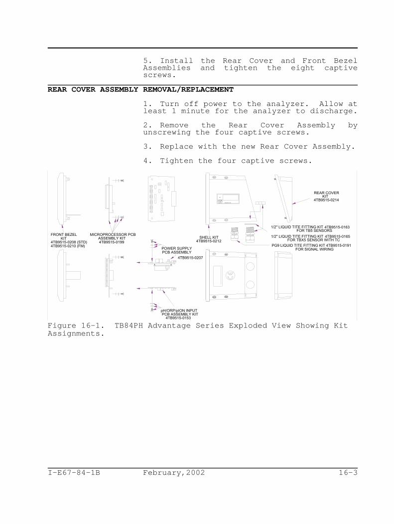
FRONT BEZELKIT
4TB9515-0210 (FM)
REAR COVERKIT
4TB9515-0214
FOR SIGNAL WIRING
4TB9515-0165
POWER SUPPLYPCB ASSEMBLY
4TB9515-0207
pH/ORP/pION INPUTPCB ASSEMBLY KIT
4TB9515-0153
SHELL KIT4TB9515-0212
MICROPROCESSOR PCBASSEMBLY KIT4TB9515-0199
CARSON CITY, NV.
TAG
FOR TB5 SENSORS4TB9515-01631/2" LIQUID TITE FITTING KIT
1/2" LIQUID TITE FITTING KITFOR TBX5 SENSOR WITH TC
PG9 LIQUID TITE FITTING KIT 4TB9515-01914TB9515-0208 (STD)
I-E67-84-1B February,2002 16-3
5. Install the Rear Cover and Front BezelAssemblies and tighten the eight captivescrews.
REAR COVER ASSEMBLY REMOVAL/REPLACEMENT
1. Turn off power to the analyzer. Allow atleast 1 minute for the analyzer to discharge.
2. Remove the Rear Cover Assembly byunscrewing the four captive screws.
3. Replace with the new Rear Cover Assembly.
4. Tighten the four captive screws.
Figure 16-1. TB84PH Advantage Series Exploded View Showing KitAssignments.

I-E67-84-1B February,2002 16-4
I-E67-84-1B February,2002 17-1
SECTION 17 - SUPPORT SERVICES
INTRODUCTION
ABB Controls is ready to help in the use andrepair of its products. Requests for salesand/or application services should be made tothe nearest sales or service office.
Factory support in the use and repair of theTB84PH Advantage Series analyzer can beobtained by contacting:
ABB Inc.9716 S. Virginia ST., Ste.EReno, Nevada 89511 USAPhone: 1(775)850-4800Facsimile: 1(775)850-4808Web Site: www.abb.com/instrumentation
RETURN MATERIALS PROCEDURES
If any equipment should need to be returnedfor repair or evaluation, please contact ABBInc. at (775)883-4366, or your local ABBrepresentative for a Return MaterialsAuthorization (RMA) number. At the time theRMA number is given, repair costs will beprovided, and a customer purchase order willbe requested. The RMA and purchase ordernumbers must be clearly marked on allpaperwork and on the outside of the returnpackage container (i.e., packing box).
Equipment returned to ABB Inc. with incorrector incomplete information may result insignificant delays or non-acceptance of theshipment.
REPLACEMENT PARTS
When making repairs at your facility, orderspare parts kits from a ABB sales office.Provide the following information.
1. Spare parts kit description, part number,and quantity.
2. Model and serial number (if applicable).
3. ABB instruction manual number, page number,and reference figure that identifies the spareparts kit.
When you order standard parts from ABB, usethe part numbers and descriptions fromRECOMMENDED SPARE PARTS KITS sections. Order

I-E67-84-1B February,2002 17-2
parts without commercial descriptions from thenearest ABB sales office.
RECOMMENDED SPARE PARTS KITSTable 17-1. Spare Parts Kits
Part Number Description
4TB9515-0124 Pipe Mount Kit
4TB9515-0125 Hinge Mount Kit
4TB9515-0123 Panel Mount Kit
4TB9515-0156 Wall Mount Kit
4TB9515-0208 Front Bezel Kit - Standard
4TB9515-0210 Front Bezel Kit - FM Version
4TB9515-0212 Shell Kit
4TB9515-0214 Rear Cover Kit
4TB9515-0163 ½" Liquid-Tite Cable GripFitting Kit - Compatible withTBX5 Sensors
4TB9515-0165 ½" Liquid-Tite Cable GripFitting Kit - Compatible withTB5 Sensors
4TB9515-0191 PG9 Liquid-Tite Cable GripFitting Kit - Compatible withmost signal cabling sizes
4TB9515-0198 Complete Cable Grip Kit - Two½" Liquid-Tite Cable Grips(p/n 4TB9515-0165) and threePG9 Liquid-Tite Cable Grips(p/n 4TB9515-0165)
4TB9515-0207 Power Supply PCB Assembly Kit
4TB9515-0199 Microprocessor PCB AssemblyKit
4TB9515-0153 pH/ORP/pION Input PCBAssembly Kit
4TB9515-0164 BNC/TC to TB84PH Pin Adapter
4TB9515-0166 BNC to TB84PH Pin Adapter w/½" Liquid-Tite Fitting ForSensors w/ BNC (i.e., TB5Sensors)

I-E67-84-1B February,2002 17-3


I-E67-84-1B February,2002 A-3
analyzer.T = Temperature of the solution in Co
after applying the factory andprocess calibration values.
For example, solution coefficients for purewater applications are:
Pure Water = +0.18 pH/10 Co
Pure Water w/ 1ppm Ammonia = +0.31 pH/10 Co
For the TB84PH Advantage Series analyzer, thesolution coefficient will either add (+) orsubtract (-) a configured amount of theprocess variable per 10 C to the Nernstiano
compensated process variable. Thus, anapplication having a process liquid thatdecreases in its pH value as the temperatureincreases should use a positive (+) solutioncoefficient correction factor. Conversely, anapplication having a process liquid thatincreases in its pH value as the temperatureincreases should use a negative (-) solutioncoefficient correction factor. For ORP andpION analyzer types, the solution coefficientadjusts the uncompensated process variable anddoes not use the Nerstian relationship.

I-E67-84-1B February,2002 A-4
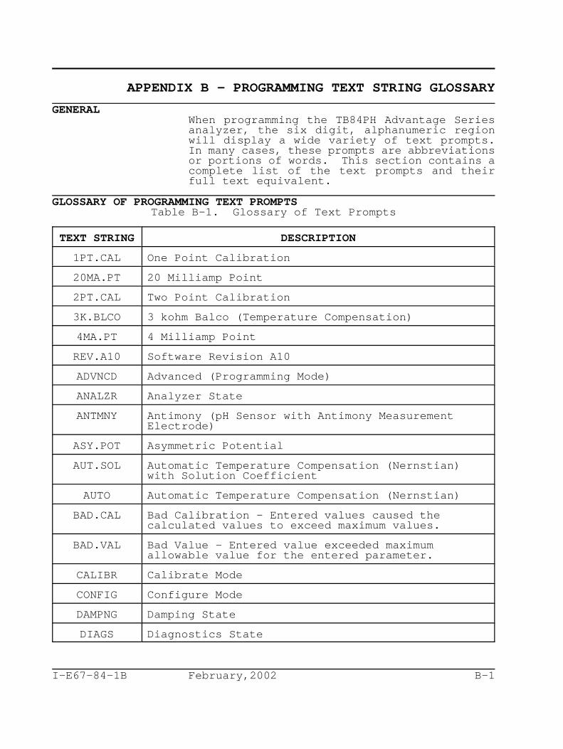
I-E67-84-1B February,2002 B-1
APPENDIX B - PROGRAMMING TEXT STRING GLOSSARY
GENERALWhen programming the TB84PH Advantage Seriesanalyzer, the six digit, alphanumeric regionwill display a wide variety of text prompts.In many cases, these prompts are abbreviationsor portions of words. This section contains acomplete list of the text prompts and theirfull text equivalent.
GLOSSARY OF PROGRAMMING TEXT PROMPTSTable B-1. Glossary of Text Prompts
TEXT STRING DESCRIPTION
1PT.CAL One Point Calibration
20MA.PT 20 Milliamp Point
2PT.CAL Two Point Calibration
3K.BLCO 3 kohm Balco (Temperature Compensation)
4MA.PT 4 Milliamp Point
REV.A10 Software Revision A10
ADVNCD Advanced (Programming Mode)
ANALZR Analyzer State
ANTMNY Antimony (pH Sensor with Antimony MeasurementElectrode)
ASY.POT Asymmetric Potential
AUT.SOL Automatic Temperature Compensation (Nernstian)with Solution Coefficient
AUTO Automatic Temperature Compensation (Nernstian)
BAD.CAL Bad Calibration - Entered values caused thecalculated values to exceed maximum values.
BAD.VAL Bad Value - Entered value exceeded maximumallowable value for the entered parameter.
CALIBR Calibrate Mode
CONFIG Configure Mode
DAMPNG Damping State
DIAGS Diagnostics State

TEXT STRING DESCRIPTION
I-E67-84-1B February,2002 B-2
DISABL Disable
END.MV Ending Millivolt Point (For Specific IonConcentration configuration only).
END.MAG Ending Magnitude Point (For Specific IonConcentration configuration only).
FAIL.HI Fail High (i.e., 20 mA)
FAIL.LO Fail Low (i.e., 4 mA)
HI.VAL High Calibration (Buffer or Standard) Value
ION.CAL Specific Ion Calibration
ION.CON Specific Ion Concentration
ISO.PT Isopotential Point
---KRZ Reference Impedance in kohms where --- is theimpedance value.
LO.VAL Low Calibration (Buffer or Standard) Value
MAGS Magnitudes - Number of decades the output rangewill cover (For Specific Ion Concentrationconfiguration only).
MV/10C Millivolt per 10 C (Solution Coefficient value foro
Automatic Nernstian with Solution CoefficientTemperature Compensation)
NEW.VAL New Calibration Value - The PV or Temperaturevalue expected during a One Point or TemperatureCalibration.
NON.LIN Non-Linear Output State
ORP.CAL ORP Calibration State
OUT.CAL Output Calibration State
PASSWD Security Password
PH.CAL pH Calibration State
PH.GLAS pH Glass (pH Sensor with Glass MeasurementElectrode)
PT 100 Pt100 Ohm RTD
REF Z Reference Impedance
REL.HLD Release Hold

TEXT STRING DESCRIPTION
I-E67-84-1B February,2002 B-3
RERANG Rerange State
RST.ALL Reset All Parameters to Factory Settings
RST.CAL Reset Calibration Constant and Data to FactorySettings
RST.CON Reset Configurations to Factory Defaults
RST.SEC Reset Security - Remove any existing security.
SAFE.MD Safe Mode State
SEC.DSP Secondary Display Mode
SECS Seconds
SECUR Security Mode
SPK.MAG Spike Output Magnitude
SPK.OFF Spike Output Function set to Off (i.e., Disable)
STABL? Is the displayed Process Variable Stable?
TC.TYPE Temperature Compensation Type State
TMP.CAL Temperature Calibration State
TMP.SNS Temperature Sensor Type State
TMP C Temperature in degrees Celsiuso
VALENC Ion Valence State (For Specific Ion Concentrationconfiguration only).
X-1 Nonlinear X Input Point value for Breakpoint 1 inpercentage of input.
Y-1 Nonlinear Y Output Point value for Breakpoint 1 inpercentage of output.

T B 8 2 P H F u n c t io n F lo w T r e e
M e a s u r e
C a l ib r a t e O u t /H o ld C o n f ig u r e S e c u r i t y D is p la y
p H /O R P /p IO N C a l i b r a t io n
1 p o in t c a l ib r a t io n2 p o in t c a l ib r a t io n
T e m p e r a t u r e C a l i b r a t io n
E d i t C a l ib r a t i o n
R e s e t C a l i b r a t io n
O u t p u t C a l i b r a t io n
H o ld / R e le a s e H o ld O u t p u t
R e r a n g e O u t p u t4 m A p o in t
2 0 m A p o in t
M o d i f y /V ie w
B a s ic /A d v a n c e d
A n a ly z e rp H ,O R P , p IO N
Io n C o n c e n tr a t io nu n i ts
v a le n c em a g n i tu d e ( lo g )e n d m a g n i tu d e
e n d m i l l iv o l t
S e n s o r T y p ep H , A n t im o n y
C u s to m
R e fe r e n c e In p e d a n c e
T e m p e r a t u r e S e n s o r
N o n e , 3 k B a lc o , P t1 0 0
T e m p e r a t u r e C o m p e n s a t io nM a n u a l , A u to , A u to
S o lu t io n
A n a lo g O u t p u t O n e R a n g e
4 m A /2 0 m A V a lu e s o r0 m A /2 0 m A V a lu e s
N o n l in e a r
D a m p in gS e c o n d s
S a f e M o d e O n eH ig h /L o w
D i a g n o s t ic sO n /O ff
S e c u r e d M o d e sC a l ib r a te
O u tp u tC o n f ig u r e
P a s s w o r d
T e m p e r a t u r e ( C )
T e m p e r a t u r e ( F )
C u r r e n t O u t p u t ( m A )
S e n s o r I n p u t ( m V )
D i a g n o s t ic A l a r m s
S p ik e O u t p u t S t a t e
D a m p in gS e c o n d s
S p ik e O u t p u tO n /O ff
S o f t w a r e R e v is i o n
S p ik e N o t i f i c a t io nP e r c e n t M a g n i tu d e
N o t e : F u n c t i o n s in i t a l ic s a r e o n ly a v a i la b l e o n T B 8 2 v e r s io n s w i t h A d v a n c e d p r o g r a m m in g n o m e n c l a t u r e o p t i o n .
S P T /T u n e
R e la y 1
R e la y 2
R e la y 3
A n a lo g O u t p u t T w o R a n g e
P V o r T e m p e r a tu r e4 m A /2 0 m A V a lu e s o r
0 m A /2 0 m A V a lu e s
R e la y O u t p u t O n e S e tp o in t , D ia g n o s t ic s ,
C y c le T im e r , o r C le a n e r
R e la y O u t p u t T w o S e tp o in t , D ia g n o s t ic s ,
C y c le T im e r , o r C le a n e r
R e la y O u t p u t T h r e e
S e tp o in t , D ia g n o s t ic s , C y c le T im e r , o r C le a n e r
S a f e M o d e T w oH ig h /L o w
I-E67-84-1B February,2002 B-4
Figure B-1. TB84PH Programming Function Flow Chart.

I-E67-84-1B February,2002 C-1
APPENDIX C - CONFIGURATION WORKSHEETS


Products and customer supportAutomation SystemsFor the following industries:— Chemical & Pharmaceutical— Food & Beverage— Manufacturing— Metals and Minerals— Oil, Gas & Petrochemical— Pulp and Paper
Drives and Motors— AC and DC Drives, AC and DC Machines, AC Motors to
1kV— Drive Systems— Force Measurement— Servo Drives
Controllers & Recorders— Single and Multi-loop Controllers— Circular Chart and Strip Chart Recorders— Paperless Recorders— Process Indicators
Flexible Automation— Industrial Robots and Robot Systems
Flow Measurement— Electromagnetic Flowmeters— Mass Flowmeters— Turbine Flowmeters— Wedge Flow Elements
Marine Systems & Turbochargers— Electrical Systems— Marine Equipment— Offshore Retrofit and Refurbishment
Process Analytics— Process Gas Analysis— Systems Integration
Transmitters— Pressure— Temperature— Level— Interface Modules
Valves, Actuators and Positioners— Control Valves— Actuators— Positioners
Water, Gas & Industrial Analytics Instrumentation— pH, Conductivity and Dissolved Oxygen Transmitters and
Sensors— Ammonia, Nitrate, Phosphate, Silica, Sodium, Chloride,
Fluoride, Dissolved Oxygen and Hydrazine Analyzers— Zirconia Oxygen Analyzers, Katharometers, Hydrogen
Purity and Purge-gas Monitors, Thermal Conductivity
Customer supportWe provide a comprehensive after sales service via a Worldwide Service Organization. Contact one of the following offices for details on your nearest Service and Repair Centre.
USAABB Inc.Tel: +1 800 HELP 365 (435 7365)Fax: +1 860 298 7669
UKABB LimitedTel: +44 (0)1453 826661Fax: +44 (0)1453 829671
ChinaABB Engineering (Shanghai) LimitedTel: +86 (0) 21 6105 6666Fax: +86 (0) 21 6105 6992
Client WarrantyPrior to installation, the equipment referred to in this manual must be stored in a clean, dry environment, in accordance with the Company's published specification.Periodic checks must be made on the equipment's condition. In the event of a failure under warranty, the following documentation must be provided as substantiation:— A listing evidencing process operation and alarm logs
at time of failure.— Copies of all storage, installation, operating and
maintenance records relating to the alleged faulty unit.

Contact us
OI/T
B84
PH
–EN
Rev
. C10
.201
2
ABB Inc.Process Automation843 N Jefferson StreetPO Box 831Lewisburg 24901-9509USATel: +1 304 647 4358Fax: +1 304 645 4236
ABB LimitedProcess AutomationOldends LaneStonehouseGloucestershire GL10 3TAUKTel: +44 1453 826 661Fax: +44 1453 829 671
ABB Engineering (Shanghai) Ltd.Process AutomationNo5, Lane 369, Chuangye Road201319, ShanghaiP.R. ChinaPhone: +86 (0) 21 6105 6666Fax: +86 (0) 21 6105 6992
www.abb.com
NoteWe reserve the right to make technical changes or modify the contents of this document without prior notice. With regard to purchase orders, the agreed particulars shall prevail. ABB does not accept any responsibility whatsoever for potential errors or possible lack of information in this document.
We reserve all rights in this document and in the subject matter and illustrations contained therein. Any reproduction, disclosure to third parties or utilization of its contents in whole or in parts – is forbidden without prior written consent of ABB.
Copyright© 2012 ABBAll rights reserved
E67-84-1B
Sales
Service
Software


![The Games! The Upsets! The Madness!: March Madness [INFOGRAPHIC]](https://img.dokumen.tips/doc/110x75/577cdcc71a28ab9e78ab621f/the-games-the-upsets-the-madness-march-madness-infographic.jpg)