Embed Size (px)
Citation preview

Offshore Measurement System for Relative Displacements of Grouted Joints
Niklas SCHOLLE*, Ludger LOHAUS* *Institute of Building Materials Science, Leibniz Universität Hannover
(Appelstraße 9A, 30167 Hannover / [email protected])
Abstract. The experience with regard to the design and execution of Grouted Joints for OWC’s is primarily based on small- and large-scale experimental tests as well as calibrated numerical models. Now, the German offshore wind park “alpha ventus” enables measurements of structural behaviour in full-scale wind energy turbines. A prototype measurement system was installed on a Tripod support structure in order to monitor the displacements of a Grouted Joint. This article deals with the conception, application and analysis of the measurement data from this prototype.
1. Introduction
Depending on the water depth, soil, sea and current conditions as well as structural-specific factors, various support structures and foundations are used for offshore wind turbines [1]. In addition to the most common support structure - the Monopile - , which is characterized by a large-scale steel pipe, other support structures with three or four foundation piles such as Tripile, Tripod or Jacket are used. The connection between the support structure and the foundation pile is achieved by casting a special node called “Grouted Joint”. A mineral grout material is pumped into the gap between the foundation pile and the sleeve which is connected to the support structure. Hence, the Grouted Joint constitutes a force-fitted connection between the foundation pile and the support structure.
The mechanical properties of Grouted Joints are influenced by the offshore conditions and the execution process [2]. Furthermore, changes occurring at the connection as a result of the load compositions during its lifetime are of high interest. Once filled, inspection of the grouted connection would be very difficult. This raises the need for some practical options to monitor the condition of the grouted connection. The stiffness as a relation between stress and strain gives a quantitative comparison on the condition of the connection. Assuming that the stress in the grouted connection can be evaluated by a calibrated finite element model, the related strain or deformation components have to be recorded directly at the connection.
The offshore wind park (OWP) “alpha ventus” enables measurements of the structural behaviour as well as the testing of new measurement systems directly at offshore wind turbines (OWT) [3]. A prototype of such a measurement system was installed at a Tripod support structure in this OWP to monitor the displacements of a Grouted Joint. Since the grouted connection of this Tripod structure is located at about 25 m below sea level, the realization of the measurement system for monitoring the relative displacements of the Grouted Joint was very challenging.
Civil Structural Health Monitoring Workshop (CSHM-4) - Poster 08
License: http://creativecommons.org/licenses/by/3.0/

2. Description of the General Measurement Concept
Contrary to other structural mechanical measurements in OWT, the in-situ determination of displacements of Grouted Joints has to fulfill special requirements. Due to the specified execution process, it is practically not possible to install a measurement system during the onshore production of the structural components. There are offshore related requirements arising from external influences such as sea currents, corrosion and marine fouling. The technical and logistical challenges during the installation as well as the unknown geometrical conditions should also be taken into consideration. The following main requirements were identified during the development process of the measurement system. Possibility for external subsequent installation Possibilities for individual and flexible attachment High robustness against corrosive environmental conditions
Figure 1. General Concept of the Measurement System
Figure 1 shows the general concept of the measurement system. The relative displacements between the pile and the sleeve are recorded at the head of the Grouted Joint of the Tripod structure.
A flexible magnetically operating fixing structure with ball joints, which swells on contact with seawater to get the required stiffness, transfers the movements of the pile and sleeve into a box where sensors record the relative displacement. The box essentially consists of a body housing that creates a corrosion-protected space for the sensors. It is made up of two vertically opposite circular stainless steel plates, which are enclosed by two layers of moveable rubber bellows. Inductive displacement transducers are installed on the upper plate and they scan the relative displacements in relation to the lower plate.
3. Preparation, Calibration and Application
A prototype of the measurement system was produced. Figure 2 shows the stainless steel components on the left, the rubber bellow that protects the sensors in the middle and the switchable industrial magnets and ball joints on the right. Because of the rubber bellows the two circular stainless steel plates can almost move freely without influencing each other.
© DEWI

Figure 2. Components of the prototype
Figure 3 shows a compilation of the installed sensors. A total of four linear displacement transducers were installed: two for displacement measurements in vertical direction (V1 + V2) and two in horizontal direction (H1 + H2). Two “dummy” transducers are added (D1 + D2) to generate a constant output signal. Furthermore, a standardized temperature sensor (T) was installed. This enables a subsequent adjustment of time-dependent effects on the measurement signal. A leak measuring device was installed at the bottom of the box to check for leaks of seawater. This device sends an output signal only in the presence a conductive fluid such as seawater.
Figure 3. Sensor Arrangement
The measurement system was calibrated by mounting it on a test bench with two movable steel plates (figure 4) after its fabrication. Predefined relative displacements between both steel plates were applied, recorded and compared using an external measurement system to identify the linearity factors of the installed displacement transducers within the whole fixing structure.
H1 H2
D1
D2
Distance Limitation
V1 V2
Distance Limitation
T
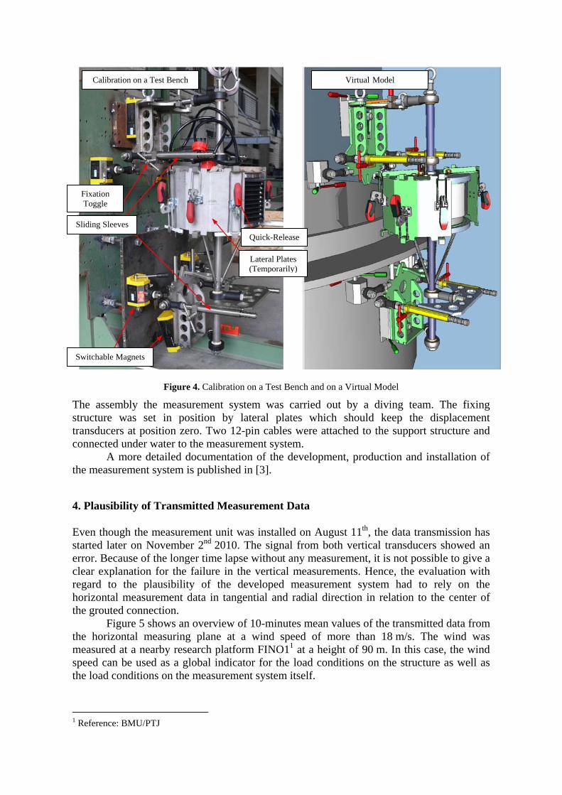
Figure 4. Calibration on a Test Bench and on a Virtual Model
The assembly the measurement system was carried out by a diving team. The fixing structure was set in position by lateral plates which should keep the displacement transducers at position zero. Two 12-pin cables were attached to the support structure and connected under water to the measurement system.
A more detailed documentation of the development, production and installation of the measurement system is published in [3].
4. Plausibility of Transmitted Measurement Data
Even though the measurement unit was installed on August 11th, the data transmission has started later on November 2nd 2010. The signal from both vertical transducers showed an error. Because of the longer time lapse without any measurement, it is not possible to give a clear explanation for the failure in the vertical measurements. Hence, the evaluation with regard to the plausibility of the developed measurement system had to rely on the horizontal measurement data in tangential and radial direction in relation to the center of the grouted connection.
Figure 5 shows an overview of 10-minutes mean values of the transmitted data from the horizontal measuring plane at a wind speed of more than 18 m/s. The wind was measured at a nearby research platform FINO11 at a height of 90 m. In this case, the wind speed can be used as a global indicator for the load conditions on the structure as well as the load conditions on the measurement system itself.
1 Reference: BMU/PTJ
Virtual ModelCalibration on a Test Bench
Lateral Plates (Temporarily)
Quick-Release
Fixation Toggle
Sliding Sleeves
Switchable Magnets

The measurement data sequence in figure 5 shows two main characteristics that are explained below.
1. Several “jumps” at points of high wind speeds 2. Irregular development of measured tangential displacement starting in June 2011
Figure 5. Overview of the Horizontal Relative Displacement
First of all, the trend shows clear irreversible jumps at several points of high wind speeds. It has to be mentioned that these jumps are far beyond the expected size of the horizontal displacement of the grouted connection. A closer look at of these jumps is illustrated using the storm event on February 5, 2011.
Figure 6. Storm Event on February 5th 2011
Figure 6
Figure 9
Detail 2
Detail 1
1.2.

Figure 6 shows a 12 hour interval of the relative displacements at the storm event. In addition to the 10-minute mean value, the minimum and maximum values are also plotted. The global jump shown in figure 5 can be divided into sub-groups of smaller jumps depending on an appropriate resolution of the plot.
For further interpretations, it has to be analyzed what exactly happens at periods of constant signal and what happens directly at these irreversible jumps. Exemplarily the two marked points in time (figure 6) will be analyzed.
Figure 7. Radial Displacement and Structural Respond (Detail 1)
The comparison between the radial displacement and the measurement data from a strain gauge placed on a brace of the support structure (figure 7) shows a high correlation between these two independent signals. The high structural stresses correspond with the high relative displacements. Furthermore, the characteristics of the relative displacement development are defined by a reversible behaviour. These two characteristics indicate a functioning measurement system.
However, as shown in figure 8, a closer look at the detail 2 from figure 6 shows that the tangential measurement jumps for a duration of only about 0.2 seconds. This very fast tangential movement contradicts the expected behaviour of a grouted connection. There is still a visible correlation between relative displacement and structural response, if the offset of the jump is taken into account. The subsequent size of the relative displacement does not seem to be affected by this jump. The jumps short duration and the unaltered development of the relative displacement lead to the conclusion that the deformation did not occur in the grouted connection but in the measurement system itself. It is suggested that due to the increased current of the seawater at the ongoing storm event, the fixation construction of the measurement system might be subjected to increased loads. The load level exceeds the friction-based resistance of the implemented ball joints thereby leading to a very sudden deformation. After the occurrence of the jump, the ball joints friction can resist the external loads again and the fixation construction almost regains its old stiffness.

Figure 8. Tangential Displacement and Structural Respond (Detail 2)
The second characteristic is the irregular development of the tangential relative displacement measurement at the beginning of June 2011. Figure 9 also indicates irregularities in the radial displacement starting at the end of June 2011.
Figure 9. Relative Displacement and Leakage Measurement
As shown in Figure 9, the leakage sensor detects the conductivity of a fluid inside the box at the beginning of May 2011. This conductivity indicates an entrance of seawater into the oil-protected box. The reason for the irregularities is the corrosion of the sensors and their

connections. Consequently, a further analysis of the measurement data would not be reasonable.
6. Disassembly
The measurement system was disassembled on June 22nd 2012 by the diving team without any problems, because the fixing magnets were still functional. The fixation construction itself showed clear traces of corrosion and marine fouling; especially the welding seams, tapped holes and screw-nuts (see Figure 10).
Figure 10. Components of the Disassembled Measurement System
The cable bushing at the upper circular stainless steel plate could be identified as the reason for the loss of the corrosion protection of the sensors. Ongoing examinations are being carried out to identify areas of corrosion in order to detect vulnerabilities of the actual construction and provide a basis for further developments.
6. Summary
Monitoring relative displacements of Grouted Joints is very challenging, because of the special environmental and logistical boundary conditions. As a result, defining the requirements for the construction of an offshore-suitable measurement system is not an easy task. Nevertheless, a prototype of such a measurement system was produced and installed at a Grouted Joint in the OWP “alpha ventus”. The transmitted measurement data were analyzed with respect to its plausibility. This analysis has revealed that the stiffness of the fixation construction was not sufficient enough to withstand the high impacts at storm events. The conceptual revision and further development of the system is subject of an ongoing research project at the Institute of Building Materials Science.
References
[1] Schaumann P., Böker, C., Rutkowski, T., Wilke F.: Tragstrukturen für Windenergieanlagen. Stahl-baukalender (2007), pp. 570-645. [2] Lohaus L., Lindschulte N., Scholle N., Werner M.: Betontechnik für Grouted Joints – Baustoffliche und bauausführungstechnische Anforderungen. Stahlbau Volume 81, Issue 9 (2012), pp. 689-694. [3] Lohaus L., Lindschulte N., Scholle N.: Zusätzliche Untersuchungen an den Grouted Joints. In: Rolfes et.al: GIGAWIND alpha ventus Jahresbericht 2010, Förderkennzeichen: 0325032, 0325032A (2011), pp. 25-32.