Embed Size (px)
Citation preview

OFDMA Cellular Access and LTE
Marceau Coupechoux
10 Feb 2021
MC OFDMA Cellular Access 10 Feb 2021 1 81
Outline I1 Introduction
2 How to reduce latency
3 How to increase data rates General characteristics of the PHY layerMulticarrier transmissionsMultiple antenna techniques
4 Radio resource organizationFrame StructureReference SignalsResource elements and blocksDownlink channelsUplink channels
5 How to synchronize ObjectifsCell search
MC OFDMA Cellular Access 10 Feb 2021 2 81
Outline II6 How to access the network
ObjectivesRandom access
7 How to send and receive data ObjectivesResource allocationSchedulingError controlMeasurements
8 Terminals categories
9 Summary on channels
10 Conclusion
MC OFDMA Cellular Access 10 Feb 2021 3 81
Introduction
Section 1
Introduction
MC OFDMA Cellular Access 10 Feb 2021 4 81
Introduction
Introduction
LTE a 3GPP standard frozen in Dec 2008Many concepts are coming from the preceding standardsImportant changes however
Multi-carrier transmissionSimplified architecture
LTE-Advanced fulfills the requirements of IMT-Advanced (4G)Standardization is evolving in parallel with the evolutions of HSPA+(releases R7 and R8)
MC OFDMA Cellular Access 10 Feb 2021 5 81
Introduction
3GPP standard evolution
Release Date Main evolutions
R99 Mar 2000WCDMAUTRAN radio interfaceATM transport network
R4 Mar 2001 IP in the transport network of UTRANR5 June 2002 HSDPA on the downlinkR6 March 2005 HSUPA on the uplinkR7 Dec 2007 HSPA+ and MIMO techniques
R8 Dec 2008 HSPA+ evolutionsLTE definition
R9 Dec 2009 MBMS for LTE
R10 June 2011 LTE-Advanced definitionCarrier aggregation relays HetNets
R11 Mar 2013 LTE-Advanced further enhancementsCoMP energy saving
R12 Mar 2015LTE-Advanced further enhancementsMachine Type Communications D2Dmission critical communications
R13 Mar 2016 LTE-Advanced ProLicensed Assisted Access 3D beamforming
Table ndash Evolution of 3GPP releases (source httpwww3gpporgspecsreleaseshtm)
MC OFDMA Cellular Access 10 Feb 2021 6 81
How to reduce latency
Section 2
How to reduce latency
MC OFDMA Cellular Access 10 Feb 2021 7 81
How to reduce latency
E-UTRAN architecture I
Answer flat architecture smarter BS and frequent radio resourceallocation (TTI = 1 ms vs 20 ms in UMTS and 2 ms in HSPA)
The radio access network is called Evolved-UTRAN
E-UTRAN = eNodes-B interconnected via X2 interface
E-UTRAN is connected to the Evolved Packet Core (EPC) via S1interface
MC OFDMA Cellular Access 10 Feb 2021 8 81
How to reduce latency
E-UTRAN architecture II
S1
S1S1
S1
X2
X2X2
E-UTRANeNB
eNB
eNB
MMES-GW MMES-GW
Figure ndash E-UTRAN architecture (from [2])
MC OFDMA Cellular Access 10 Feb 2021 9 81
How to reduce latency
E-UTRAN architecture III
Mobility Management Entity (MME) = control plane
Serving Gateway (S-GW) = user planeRNC disappears and the base station (eNB) gets augmentedfonctionalities
PHY and MAC layers (typical since GSM)Fast scheduling and HARQ (like in HSPA)New RLC PDCP RRC
Consequence scheduling retransmissions link adaptation (ie ofdata rates as a function of the radio conditions) and reconfigurationdecisions are taken closer to the radio link
MC OFDMA Cellular Access 10 Feb 2021 10 81
How to reduce latency
Protocol stack I
PDCP
RLC
MAC
PHY
PDCP
RLC
MAC
PHY
UE eNode-B
user plane
control plane
PDCP
RLC
MAC
PHY
PDCP
RLC
MAC
PHY
UE eNode-B
RRC
NAS NAS
MME
RRC
Figure ndash Protocol stack in user and control place of E-UTRAN (from [2])
MC OFDMA Cellular Access 10 Feb 2021 11 81
How to reduce latency
Protocol stack II
PHY RF processingError detection correctionTransmission techniques (multi-carrier modulation MIMO)Synchronization (time frequency)Measurements
MAC Mapping of logical channels to transport channelsMultiplexing demultiplexing of transport channelsFast scheduling every 1 msHARQ retransmissionsRandom accessTiming advanceTransport format selectionPriority management between logical channels
MC OFDMA Cellular Access 10 Feb 2021 12 81
How to reduce latency
Protocol stack IIIRLC
ARQ retransmissions (mode AM)Concatenation segmentation reassembling of RLC SDUsResegmentation of RLC PDUs in case of retransmissionIn sequence delivery of higher layers PDUsDetection of duplicated RLC PDUs
PDCP IP header compression decompression (ROHC)In sequence delivery (RLC AM)Duplicatas detectionRetransmission of PDCP PDUs in case of handover (RLC AM)Cyphering decyphering of data
RRC Radio resource managementMobility managementMeasurements feedbacksRadio bearer control
MC OFDMA Cellular Access 10 Feb 2021 13 81
How to reduce latency
Remember
Network latency Keep this in mind Flat architecture no more RNCE-UTRAN = eNB EPC = MME and SGW X2 and S1 interfacesPHY layer fast scheduling retransmissions in the eNBTTI = 1 ms
MC OFDMA Cellular Access 10 Feb 2021 14 81
How to increase data rates
Section 3
How to increase data rates
MC OFDMA Cellular Access 10 Feb 2021 15 81
How to increase data rates General characteristics of the PHY layer
Context
Remember the Shannon formula C asymp nantW log2(1 + SINR)
In practice however This is a not achieved upper boundThis function is bounded (by Cmax) because we use finite modulationsCapacity should be shared by all active users in the cellSome resources should be dedicated to signaling
To increase data rates we have few options Increase W but issues with inter-symbol interferenceDecrease interference with lower frequency spatial reuse but lessbandwidth per cellIncrease Cmax by densifying the modulation but the signal is moresensitive to noise and interferenceIncrease nant but signal processing algorithm complexity increasesand space is needed for antennasDensify the network in order to decrease the number of users per cellbut more sites = more investments
MC OFDMA Cellular Access 10 Feb 2021 16 81
How to increase data rates General characteristics of the PHY layer
General characteristics I
Spread spectrum is withdrawnMulti-carrier transmission rArr a new organization of radio resourcesOFDMA (DL) SC-FDMA (UL)Possible signal bandwiths 14 3 5 10 15 and 20 MHz (remember 5 MHz in UMTS 2times 5 MHz in HSPA+ with double carrier)Modulations BPSK QPSK 16-QAM 64-QAM (remember QPSKin UMTS 16-QAM in HSPA)64-QAM mandatory for the DL on the UL only cat 5 terminals canuse itConvolutional and turbo convolutional codesDuplexing TDD and FDD
MC OFDMA Cellular Access 10 Feb 2021 17 81
How to increase data rates General characteristics of the PHY layer
General characteristics II
MIMO 2 or 4 Tx 2 or 4 Rx up to 4 parallel flows can be usedMU-MIMO in DL and UL (remember no MIMO in UMTS 2times 2 inHSPA+)
FDD frequency bands around 700 800 1400 1700 1800 19002100 et 2600 MHz (800 1800 2600 MHz in France)
MC OFDMA Cellular Access 10 Feb 2021 18 81
How to increase data rates Multicarrier transmissions
OFDMOFDMA I
OFDM = a transmission techniqueAdvantages partly tackle the multi-path propagation issue highspectral efficiency simple implementation
UEeNode-B
Path 1
Path 2
Path 3
Am
plit
ud
e
Relative delays
wrt path 1Path 1 Path 2 Path 3
Delay spread τmax
Figure ndash Multi-path propagation and maximum delay spread
MC OFDMA Cellular Access 10 Feb 2021 19 81
How to increase data rates Multicarrier transmissions
OFDMOFDMA II
If τmax gt Tsymb rArr Inter-Symbol Interference (ISI)1τmax asymp channel coherence bandwidth1Tsymb asymp signal bandwidthWider is the signal bandwidth higher is the ISIOFDM divides the global bandwidth in small frequency sub-channelsor sub-carriers with bandwidth ∆f 1τmax
ISI is almost completely removed
MC OFDMA Cellular Access 10 Feb 2021 20 81
How to increase data rates Multicarrier transmissions
OFDMOFDMA III
Frequencyf1 f2 f3 Frequencyf1 f2 f3
FDM OFDM
Figure ndash Comparison between OFDM and FDM in terms of spectral efficiency
Higher spectral efficiency than FDMPartial overlapping of the sub-channels thanks to the orthogonalitybetween sub-carriers
MC OFDMA Cellular Access 10 Feb 2021 21 81
How to increase data rates Multicarrier transmissions
OFDMOFDMA IV
times
times
times
times
times
times
TSymb
f1
f2
f3f1 f2 f3
FFT
IFFT
Time domain Frequency domain
Δf=f2-f1=1TSymb
QAM
QAM
QAM
Figure ndash OFDM signal in time and frequency domains
Orthogonality When the signal of sub-carrier n is maximum thesignal of all other sub-carriers is nullOrthogonality is obtained when ∆f = 1TSymb
Time domain The OFDM symbol is the sum of modulatedsub-carriers multiplied by a rectangle (gate) function
MC OFDMA Cellular Access 10 Feb 2021 22 81
How to increase data rates Multicarrier transmissions
OFDMOFDMA V
t
Copy
path 1
path 2
path 3
TSymb
τmax
Tg Tu
Figure ndash Guard intervalcyclic prefix of an OFDM symbol
To completely remove residual ISI one adds a cyclic prefix
MC OFDMA Cellular Access 10 Feb 2021 23 81
How to increase data rates Multicarrier transmissions
OFDMOFDMA VI
SPModulation
QAM IFFTAdd
cyclic
prefixPS
Remove
cyclic
prefixPS
De-
modulation
QAMFFT SP
frequencyDomain
time
System bandwidth ~ N sub-carriers
user bandwidth~ M sub-carriers
f f
1 2
3
4
= QAM symbol1 2
3
4
Transmit antenna
Receive antenna
SP SerialParallel PS ParallelSerial
Figure ndash OFDMOFDMA transmission and reception chains
The OFDM signal is easy to modulate and demodulate
MC OFDMA Cellular Access 10 Feb 2021 24 81
How to increase data rates Multicarrier transmissions
OFDMOFDMA VIIOFDM has two drawbacks (1) Inter-carrier interference (due toimperfect synchronization or strong Doppler effect) and (2) High Peakto Average Ratio (PAPR)
Pmax
Pmoy
Power amplifier input
Am
plifi
er
outp
ut
PmaxPmoy
Saturation
Backoff
Figure ndash Peak to Average Ratio of the OFDM signal
MC OFDMA Cellular Access 10 Feb 2021 25 81
How to increase data rates Multicarrier transmissions
OFDMOFDMA VIII
OFDM = transmission technique
OFDMA = multiple access method based on OFDM
Groups of sub-carriers can be allocated to different users
rArr no intra-cell interference (6= CDMA)
Radio resource allocation in the timefrequency domain
MC OFDMA Cellular Access 10 Feb 2021 26 81
How to increase data rates Multicarrier transmissions
SC-FDMA I
High PAPR rArr an issue for the ULSC-FDMA = Transmission technique with low PAPR for the UL
SPModulation
QAM
IFFTNgtM
points
Add
cyclic
prefixPS
Remove
cyclic
prefixPS
De-
modulation
QAM
FFTNgtM
pointsSP
FFTM
points
0
0000
System bandwidth ~ N sub-carriers
user bandwidth~ M sub-carriers
f
IFFTM
points
0
0000
time frequencyDomain
time
f
1
2
3
4
1
2
3
4
1
2
3
4
1
2
3
4
3 = QAM symbols of a user1 2 4
Transmit antenna
Receive antenna
SP SerialParallel PS ParallelSerial
Figure ndash SC-FDMA transmission and reception chains
MC OFDMA Cellular Access 10 Feb 2021 27 81
How to increase data rates Multicarrier transmissions
SC-FDMA II
The FFT spreads every QAM symbol over M sub-carriers
Every sub-carrier successively carriers all QAM symbols
At a given instant a unique QAM symbol is transmitted
The resulting PAPR is thus the same as for a QAM modulation
The remaining N minusM sub-carriers are available and can be allocatedto other users
MC OFDMA Cellular Access 10 Feb 2021 28 81
How to increase data rates Multicarrier transmissions
LTE configurations I
Configuration ∆f (kHz) Cyclic prefix (micros) Tu (micros)Normal prefix 15 52 (first symbol) 666
47 (other symbols)Extended prefix 15 167 666
Table ndash OFDM parameters on the downlink of LTE
Normal configuration 7 OFDM symbols per slot small prefixduration rArr relatively small cells (cell radius lt 2 Km)Extended configuration higher prefix duration 6 OFDM symbols perslot rArr larger cells (up to 10 Km) and single frequency networks (forbroadcast multicast services)
MC OFDMA Cellular Access 10 Feb 2021 29 81
How to increase data rates Multicarrier transmissions
LTE configurations II
Transmission techniques Keep this in mind OFDM advantages combat and take advantage of multi-pathpropagation high spectral efficiency easy and cheap implementationOFDM drawbacks Inter-carrier interference (ICI) PAPROFDMASC-FDMA are multiple access schemesSC-FDMA advantage A solution for a low PAPR ULSC-FDMA drawback A user can be allocated only a set of contiguoussub-carriersSpectral separation between sub-carriers is constant equal to 15 KHzwhatever the total signal bandwidth
MC OFDMA Cellular Access 10 Feb 2021 30 81
How to increase data rates Multiple antenna techniques
MIMO gains
Diversity gain several independent copies of the signal are availableat the receiver improve the robustness of the signalArray gain transmission side energy is focused in one or severaldirections (beamforming) reception side more energy is captured byseveral antennas improve the SNR may reduce interferencesMultiplexing gain several parallel flows are simultaneouslytransmitted the SISO channel capacity is multiplied by min(MN)where M and N are the number of transmit and receive antennas respTypical configurations 2times 2 and 4times 2 then 4times 4
MC OFDMA Cellular Access 10 Feb 2021 31 81
How to increase data rates Multiple antenna techniques
Transmit diversity (TM2)
SFBCCoding
s2 s1s2
s1
s1
-s2
Figure ndash Transmit diversity
2 or 4 transmit antennasSpace-Time Block Code (SFBC) Alamouti code [4] in the frequencydomainImproves the robustness of the signal without increasing the data rateOpen loopBackup transmission mode for other modes
MC OFDMA Cellular Access 10 Feb 2021 32 81
How to increase data rates Multiple antenna techniques
Spatial multiplexing (TM3 open loop TM4 closed loop)
Pre-coding
flow 1
flow 2
(a) Open loop
Pre-coding
flow 1
flow 2
(b) Closed loop
Figure ndash Spatial multiplexing
Several flows are simultaneously transmitted (2 or 4 antennas)Open loop precoding matrices are known at the receiver and changein a cyclic manner at the transmitterClosed loop the UE feedbacks its preferred precoding matrix thissolution is well adapted to UEs in low mobility
MC OFDMA Cellular Access 10 Feb 2021 33 81
How to increase data rates Multiple antenna techniques
TM5 Multi-user MIMO
eNode-B
(a) DL
eNode-B
(b) UL
eNBtransmitpower
UE2
UE1
UE1
UE2
UE1
UE2
Figure ndash MU-MIMO transmission (a) on the downlink and (b) on the uplink
Two simultaneous flows on a single timefrequency resourceTechnique similar to the spatial multiplexing scheme with closed loop
MC OFDMA Cellular Access 10 Feb 2021 34 81
How to increase data rates Multiple antenna techniques
TM6 and TM7 Beamforming
Node-B
UE
Figure ndash Beamforming
An antenna array is used to create an antenna beam in the directionof the UE rArr increase useful signal power at the receiverPilot signals specific to the UE are required
MC OFDMA Cellular Access 10 Feb 2021 35 81
How to increase data rates Multiple antenna techniques
Remember
MIMO Keep this in mind Transmit diversity improves the signal robustnessSpatial multiplexing increases data rates in good radio conditionsBeamforming increases the useful signal powerOpen loop no feedback from UEs (for fast UEs)Closed loop feedback from UEs (more efficient but for slow UEs)
MC OFDMA Cellular Access 10 Feb 2021 36 81
Radio resource organization Frame Structure
Frame structure (type 1 for FDD)
0 1 2 3 18 19
One radio frame Tf = 307 200 T
s = 10 ms
One sub-frame 30 720 Ts = 1 ms
One slot Tslot
= 15 360 Ts = 05 ms
0 1 2 3 4 5 6
160 2048 144 2048 144 2048 144 2048 144 2048 144 2048 144 2048
One OFDMSC-FDMA symbol = 666 micros
512 2048
0 1 2 3 4 5
Short prefix
Extended(15 kHz)
Figure ndash Frame structure type 1 in LTE FDD for 20 MHz (from [1])
MC OFDMA Cellular Access 10 Feb 2021 37 81
Radio resource organization Reference Signals
Reference signals I
DC (Direct Current)∆f = 15 kHz
2048 sub-carriers
1200 used sub-carrierGuard band Guard band
Pilot sub-carriers(signaux de reacutefeacuterence)
Data sub-carriers
Central frequency
Figure ndash Data pilot (reference signals) and null (carrier frequency and guardbands) sub-carriers on the DL of LTE
Reference signals are required for the channel estimation and thedecoding of user data
MC OFDMA Cellular Access 10 Feb 2021 38 81
Radio resource organization Reference Signals
Reference signals II
Port 0 Port 1 Port 2 Port 3t
f One antenna port
Two antenna ports
Four antenna ports
RE used by this antenna port to transmit a RS
RE free of transmission on this port
RE
0 1 2 3 4 5 6 0 1 2 3 4 5 6
RB
Figure ndash Reference signals (from [1])MC OFDMA Cellular Access 10 Feb 2021 39 81
Radio resource organization Resource elements and blocks
Resource elements (RE) and blocks (RB) I
f
t
Slot (05 ms)
Sub-frame (1 ms)
180 kHz
UE1
UE2
UE3
UE412 s
ub
-carr
iers
of
15 K
Hz
7 OFDMSC-FDMA symbols
RE
RB
Figure ndash Resource Elements and Resource Blocks in LTE in normal configuration
MC OFDMA Cellular Access 10 Feb 2021 40 81
Radio resource organization Resource elements and blocks
Resource elements (RE) and blocks (RB) II
1 RE = 1 sub-carrier times 1 OFDMSC-FDMA symbol
1 RB = 12 sub-carriers times 7 OFDMSC-FDMA symbols
Minimum amount of resource allocated to a UE 2 successive RBs
Parameter Bandwidth (MHz)14 3 5 10 15 20
FFT size 128 256 512 1024 1536 2048Used sub-carriers 72 180 300 600 900 1200
RB 6 15 25 50 75 100
Table ndash Available radio resources vs signal bandwidth (from [3])
MC OFDMA Cellular Access 10 Feb 2021 41 81
Radio resource organization Resource elements and blocks
Remember
Radio resource organization Keep this in mind Radio resources are organized in the time-frequency domain (orslot-sub-carrier)1 radio frame (10 ms) = 10 sub-frames (1 ms) = 20 slots (0 5 ms)1 RE = 1 sub-carriers times 1 symbol1 RB = 12 sub-carriers times 7 symbolsMinimum allocation 2 successive RBs (every 1 ms)20 MHz 100 RB
MC OFDMA Cellular Access 10 Feb 2021 42 81
Radio resource organization Downlink channels
Downlink physical channels
1 2 3 4 6 7 8 9
Radio frame (10 ms)
PBCH
PSSSSS
Sub-frame (1 ms)
SSS PSS
DC
10
8 M
Hz
Slot 0 Slot 1
0 5 6 0 1 2 3 6 0 6 6
PDSCH
PDSCH
1 2 1 2 0
PDCCH1 2 or 3 OFDM symbols
signaled by the PCFICH
PCFICH
A PHICHgroup
Syste
m b
and
wid
th
Figure ndash Mapping of downlink physical channels on the radio frameMC OFDMA Cellular Access 10 Feb 2021 43 81
Radio resource organization Uplink channels
Uplink physical channels I
Time location defined by the PRACH config
f
t
Syste
m b
an
dw
idth
Frame (10 ms)
6R
B6R
B
Frequency locationdefined byhigher layers
PRACH period
1 or 2 frames depending on the PRACH configuration
PUCCH
PUCCH
PUSCH
Figure ndash Position of the PRACH PUSCH and PUCCH in the LTE frame
MC OFDMA Cellular Access 10 Feb 2021 44 81
Radio resource organization Uplink channels
Uplink physical channels II
f
tSlot (05 ms)
0 1 2 3 4 5 6
PUSCH
UE1
UE2
UE3
DM
RS
DM
RS
DM
RS
Figure ndash DMRS during a PUSCH transmission (from [1])
MC OFDMA Cellular Access 10 Feb 2021 45 81
Radio resource organization Uplink channels
Transport and logical channels
Transport channels
Control informations
Physical channels
Uplink Downlink
RACH UL-SCH
UCI
PRACH PUSCH PUCCH
DL-SCH
DCI
PDSCH PDCCH
CFI
PCFICH
HI
PHICH
PCH BCH
PBCH
MCH
PMCH
CCCH
Logical channels
DTCH
DCCH
PCCH DTCH
DCCH
BCCH MCCH MTCHCCCH
Figure ndash Mapping of physical transport and logical channels
MC OFDMA Cellular Access 10 Feb 2021 46 81
How to synchronize
Section 5
How to synchronize
MC OFDMA Cellular Access 10 Feb 2021 47 81
How to synchronize Objectifs
Objectives
Objectives time and frequency PCI (Physical Cell Identifier) andSystem Informations acquisitionPCI 504 identities classified in 168 groups of 3System Informations network identity common channelsconfiguration selectionreselectionhandover parameters informationson neighbor cells They are organized in one MIB (Master InformationBlock) and several SIBs (System Information Block)
MC OFDMA Cellular Access 10 Feb 2021 48 81
How to synchronize Cell search
Cell search I
1 Find the most powerful carrier in the operator spectrum2 PSS decoding (62 sub-carrier in the middle of the band whatever the
bandwidth) rArr the PSS broadcasts a sequence among 33 SSS decoding rArr the SSS broadcasts 2 pseudo-random sequences of
62 bits on slots 0 and 10 there are 168 possible pairs4 Radio quality evaluation using RSs rArr the UE is synchronized if the
quality is sufficient the transmitted sequence and the position of theRSs in the frame depend on the PCI so that RSs from neighboringcells do not interfere
MC OFDMA Cellular Access 10 Feb 2021 49 81
How to synchronize Cell search
Cell search II
5 PBCH decoding rArr MIB (Master Information Block) antennaconfiguration the position of the PBCH does not depend on thebandwidth it is scrambled by a sequence that depends on the PCIThe MIB includes
the bandwidth (in of RBs)PHICH parametersthe frame number
6 PCFICH decoding rArr Number of OFDM symbols dedicated toPDCCHs
7 PDCCH decoding rArr DCI message (with SI-RNTI address) givingthe location of the SIB1 in the PDSCH
8 SIB1 decoding rArr scheduling of other SIBs
9 SIBs (System Information Block) are received on the PDSCH
MC OFDMA Cellular Access 10 Feb 2021 50 81
How to access the network
Section 6
How to access the network
MC OFDMA Cellular Access 10 Feb 2021 51 81
How to access the network Objectives
Objectives
Objectives Establishment or re-establishment of the RRC connectionIntra-system handoversUpon arrival of DL or UL data whereas the UE has lost itssynchronization with the network
2 random access types contention-based conflict-freeContention-based access can be used in all casesConflict-free access for handovers or upon arrival of DL data
PRACH transmission on the uplink then transmission of a CCCHmessage signaling the reason of the access
MC OFDMA Cellular Access 10 Feb 2021 52 81
How to access the network Random access
Contention-based access I
System Information (DL-SCH)(PRACH config PRACH location preamble format sequence list)
Random Access Preamble (RACH)(size of the L2L3 message)
Random Access Response (DL-SCH)(RA-RNTITA temp C-RNTI UL allocation)
CCCH message (UL-SCH)
Collision resolution (DL-SCH)(SDU CCCH)
UEeNB
Figure ndash Contention-based access in LTE
MC OFDMA Cellular Access 10 Feb 2021 53 81
How to access the network Random access
Contention-based access II1) The UE obtains from SIB the PRACH configuration the PRACH
frequency location the preamble format the target received powerand the list of sequences to be used (64 Zadoff-Chu sequencesincluding those reserved to the conflict-free access)
3) The UE chooses at random one sequence among those available4) It sends the preamble on the PRACH with an open loop power
control the UE tries to compensate the path-loss by usingmeasurements made on DL RSs rArr power control makes sequencedetection easier at the BS
Collision several UEs have used the same sequence on the same radioresourceCapture the eNB manages to decode one of the messages in collision
MC OFDMA Cellular Access 10 Feb 2021 54 81
How to access the network Random access
Contention-based access III
5) If there is no answer from the network power ramping (like inCDMA) ie the UE stepwise increases its transmit power
6) The RAR identifies the decoded preamble + provides the timingadvance (TA) + gives an UL allocation + a temporary identity(temporary C-RNTI address)
7) CCCH message on the PUSCH = eg a RRC connection request +temporary C-RNTI
8) Collision resolution the eNB sends a copy of the CCCH message onthe DL The UE that recognizes its message adopts the temporaryC-RNTI (now its address) other UEs leave the procedure
MC OFDMA Cellular Access 10 Feb 2021 55 81
How to access the network Random access
Conflict-free access
The UE has a valid identity (C-RNTI)The eNB sends a (DCI) message on the PDCCH including theZadoff-Chu sequence to be usedCollisions are no more possible no collision resolution phase
MC OFDMA Cellular Access 10 Feb 2021 56 81
How to send and receive data
Section 7
How to send and receive data
MC OFDMA Cellular Access 10 Feb 2021 57 81
How to send and receive data Objectives
Objectives
Objectives Resource allocation tell UEs on which radio resources they will receivedata on the DL-SCH or on which resource they are allowed to transmiton the UL-SCHUE scheduling allocate RBs to UEs as a function of their demand andtheir radio conditionsError control ARQ and HARQ retransmissionsMeasurement feedbacks the UE tells the network the downlinkchannel radio quality or its preferred MIMO precoding matrix
MC OFDMA Cellular Access 10 Feb 2021 58 81
How to send and receive data Resource allocation
Resource allocation I
Location of resources in the sub-frame modulation and coding schemeare signaled in Downlink Control Information (DCI) messagestransmitted on the PDCCHs
Format Description0 Resource allocation on the PUSCH1 PDSCH resource allocation in TM1 TM2 TM71A PDSCH compact allocation and PRACH signature1B PDSCH resource allocation in TM61C PDSCH very compact allocation1D PDSCH compact allocation in TM52 PDSCH compact allocation in TM42A PDSCH compact allocation in TM33 Power control on PUCCHPUSCH (2 bits)3A Power control on PUCCHPUSCH (1 bit)
Table ndash DCI formats
MC OFDMA Cellular Access 10 Feb 2021 59 81
How to send and receive data Resource allocation
Resource allocation II
DCI 0 example A flag to differentiate 1 and 1AA flag for frequency hopping on the PUSCHResource block allocationModulation and coding scheme redundancy version for HARQHARQ new transmission indicatorA power control command for the ULCyclic shift to be applied to ZC sequence for DMRSA CQI request
Every DCI includes a CRC scrambled with a RNTI identityC-RNTI = to address a unique UEP-RNTI = paging messageSI-RNTI = SIBRA-RNTI = random access response
MC OFDMA Cellular Access 10 Feb 2021 60 81
How to send and receive data Scheduling
Scheduling I
Fast (every 1 ms) and adaptive (modulation and coding are adaptedto radio conditions) schedulingDL scheduling decisions are based on CQI feedbacks buffer statusand priorities between logical channelsUL the UE has to feedback its buffer status and radio resource needsby using either the PUCCH (scheduling request) or the UL-SCH (MACcontrol messages)
MC OFDMA Cellular Access 10 Feb 2021 61 81
How to send and receive data Scheduling
Scheduling IIAlgorithm LTE offers a new degree of freedom wrt HSPA thepossibility to schedule users on different radio blocks
Channel q
ualit
y
fPRB1 PRB2 PRB3 PRB4 PRB5
Channel UE1
Channel UE2
Channel UE3
Scheduling decisions UE2 UE3 UE1 UE3 UE2
Figure ndash Frequency Dependent Packet Scheduling (FDPS) in LTE
MC OFDMA Cellular Access 10 Feb 2021 62 81
How to send and receive data Scheduling
Scheduling III
f
t
Syste
m b
an
dw
idth
Sub-frame (1 ms)
f
t
Comb onesub-carrieris used outof two
(a) SRS transmission without frequency hopping
(b) SRS transmission with frequency hopping
Figure ndash Sounding Reference Signals (SRS) transmissions
The eNB estimates the channel quality on the UL thanks to SRS
SRS is transmitted on a bandwidth much larger than the one allocated to UEtransmissions
SRS from different UEs are multiplexed in time (different sub-frames and periods)frequency (different sets of RBs oddeven sub-carriers) or code (differentsequences)
MC OFDMA Cellular Access 10 Feb 2021 63 81
How to send and receive data Error control
ARQ and HARQ
Like in HSPA HARQ is in the MAC layer and ARQ in the RLCHARQ DL sequence number is signaled in the PDCCH ACKNACKare fed back in the PUSCH (with data) or in the PUCCHHARQ UL ACKNACK transmitted in the PHICHARQ Transparent Mode (TM) (no header no segmentation orconcatenation) Unacknowledged (UM) (header with sequencenumber) Acknowledged (AM) (ARQ)
MC OFDMA Cellular Access 10 Feb 2021 64 81
How to send and receive data Measurements
Measurements
Radio quality measurements CQI (Channel Quality Indicator) modulation (QPSK 16-QAM or64-QAM) and transport block maximum size that a UE can receivewith a BLERlt10 (Block Error Rate)RI (Rank Indicator) rank of the DL transmission = number ofindependent spatial layers that can be usedPMI (Precoding Matrix Indicator) UE preferred precoding matrix Wfor transmission modes with closed loop
Physical channels PUSCH for aperiodic feedbacks with data transmissionPUCCH for periodic feedbacks
MC OFDMA Cellular Access 10 Feb 2021 65 81
Terminals categories
Section 8
Terminals categories
MC OFDMA Cellular Access 10 Feb 2021 66 81
Terminals categories
Terminals categories
Caracteristics Cat 1 Cat 2 Cat 3 Cat 4 Cat 5Max number ofbits per TTI (DL) 10296 51024 102048 150752 299552
Max number ofbits per TTI (UL) 5160 25456 51024 51024 75376
Max data rate(DL) 10 Mbps 50 Mbps 100 Mbps 150 Mbps 300 Mbps
Max data rate(UL) 5 Mbps 25 Mbps 50 Mbps 50 Mbps 75 Mbps
64 QAM (UL) No No No No YesMIMO (DL) Option 2times 2 2times 2 2times 2 4times 4
Table ndash Terminal categories in LTE
For example the Semsong S5 is cat 4 the Semsong S6 is cat 6 (Release 1030050 Mbps) the Semsong S8 is cat1613 (Release 12 1050150 Mbps MIMO4x4 256-QAM 5CA) Semsong S10 is cat 2013 (2000 Mbps up to 8 MIMOlayers 256-QAM 7CA)
MC OFDMA Cellular Access 10 Feb 2021 67 81
Summary on channels
Section 9
Summary on channels
MC OFDMA Cellular Access 10 Feb 2021 68 81
Summary on channels
Physical channels DL I
PDSCH (Physical Downlink Shared Ch) physical shared channel for data
RS (Reference Signals) pilots required to estimate radio quality and toallow decoding on the DL
SS (Synchronization Signals) = PSS (Primary)+SSS (Secondary) for timeand frequency synchronization
PBCH (Physical Broadcast Ch) beacon MIB transmission
PCFICH (Physical Control Format Indicator Ch) tell the UEs how manyOFDM symbols are dedicated to the control part of the sub-frame (CFI)
PDCCH (Physical Downlink Control Ch) control informations (DCI resource allocation UE identity HARQ information MIMO etc)
PHICH (Physical Hybrid ARQ Indicator Ch) ACKNACK responses toHARQ transmissions from a UE (HI)
MC OFDMA Cellular Access 10 Feb 2021 69 81
Summary on channels
Physical channels UL I
In UL a UE is not able to multiplex different physical channels in the frequencydomain because of SC-FDMA limitation rArr time multiplexing is required
DMRS (Demodulation Reference Signal) used by the eNB to estimate thechannel and make radio quality measurements on the signal transmitted by theUE DMRS are sent in conjunction with PUCCH and PUSCH
SRS (Sounding Reference Signal) pilots used by the scheduler for the radioquality estimation on a bandwidth larger than the one allocated to the UE
PUCCH (Physical Uplink Control Ch) control informations UCI includingchannel quality (CQI) MIMO (closed loop) or HARQ (ACKNACK) informations
PUSCH (Physical Uplink Shared Ch) shared physical channels for data andcontrol
If a UE has data to transmit it uses the PUSCH for data and control Otherwiseit uses the PUCCH for the control
MC OFDMA Cellular Access 10 Feb 2021 70 81
Summary on channels
Transport channels DL
DL-SCH (DL Shared Ch) shared channel for data associated toPDSCHPCH (Paging Ch) broadcast of paging messages on the PDSCHBCH (Broadcast Ch) broadcast of system informations (SIBs) onthe PBCH and on the PDSCHDCI (DL Control Indicator) control information transmitted on thePDCCHs (transport format resource allocation HARQ and MIMOinformations power control commands)CFI (Control Format Indicator) number of OFDM symbols (12 or 3)used by PDCCHs at the beginning of every sub-frame CFI is sent onthe PCFICHHI (HARQ Indicator) ACK or NACK in response to a transmissionon the UL-SCH HI is transmitted on the PHICH
MC OFDMA Cellular Access 10 Feb 2021 71 81
Summary on channels
transport channels UL
RACH (Random Access Ch) random accessUL-SCH (UL Share Ch) shared channel for data and controlassociated to PUSCH User data and control informations aremultiplexed in time and frequency on the PUSCHUCI (UL Control Indicator) control information transmitted by thePUCCH (channel quality CQI closed loop MIMO informationsPMIRI ACKNACK of HARQ scheduling request)
MC OFDMA Cellular Access 10 Feb 2021 72 81
Summary on channels
Logical channels
Logical channel Type Description LinkBCCH Control System information DLPCCH Control Paging DLCCCH Control Control without RRC conn ULDLDCCH Controcircle Dedicated control ULDLDTCH Traffic user plane ULDL
Table ndash Logical channels in LTE DL and UL
BCCH (Broadcast COntrol Ch) system information associated to BCH for theMIB and DL-SCH for the SIBs
PCCH (Paging Control Ch) paging associated to PCH
CCCH (Common Control Ch) control messages between the network and UEswithout RRC connection associated to DL-SCH and UL-SCH
DCCH (Dedicated Control Ch) control messages between the network and UEswith RRC connection associated to DL-SCH and UL-SCH
MC OFDMA Cellular Access 10 Feb 2021 73 81
Conclusion
Section 10
Conclusion
MC OFDMA Cellular Access 10 Feb 2021 74 81
Conclusion
Conclusion
LTE A brand new standardA certain simplicity that is reminiscent of GSMSimilarities with 3G (channels HARQ MAC RLC etc)New features (MIMO MU-MIMO multi-carrier transmissions)
After LTE LTE-A R13 frozen in Mar 2016 (LTE Pro) R14 on goingR15 is called 5G New Radio (NR) and is the first 5G releasePeak rates of the order of 1GbpsCarrier aggregation discontinuous resource allocation on the ULMIMO 8times8 relays HetNets CoMP Self-Organized NetworksMBMS NB-IoT etc
MC OFDMA Cellular Access 10 Feb 2021 75 81
Conclusion
References I
3GPPTechnical Specification 36211 Physical channels and modulationDec 2009
3GPPTechnical Specification 36300 Evolved Universal Terrestrial RadioAccess (E-UTRA) and Evolved Universal Terrestrial Radio AccessNetwork (E-UTRAN) Overall description Apr 2010
3GPPTechnical Specification 36104 Base Station (BS) radio transmissionand reception Jun 2011
MC OFDMA Cellular Access 10 Feb 2021 76 81
Conclusion
References II
S M AlamoutiA simple transmit diversity technique for wireless communicationsIEEE J on Selected Areas in Communications 16(8) 1451ndash1458 Oct1998
MC OFDMA Cellular Access 10 Feb 2021 77 81
Conclusion
Acronyms I
AM ARQ Acknowledged ModeARQ Automatic Repeat on RequestBCCH Broadcast Control ChannelBCH Broadcast ChannelBLER Block Error RateBPSK Binary Phase Shift KeyingBS Base Station
CCCH Common Control ChannelCDMA Code Division Multiple AccessCFI Control Format Indocator
CoMP Coordinated Multi-PointCQI Channel Quality IndicatorCRC Cyclic Redundancy CodeD2D Device to DeviceDCCH Dedicated Control ChannelDCI Downlink Control InformationDL Downlink
DL-SCH Downlink Shared ChannelDMRS Demodulation Reference SignalDTCH Dedicated Traffic ChanneleNB eNode-BEPC Evolved Packet Core
E-UTRAN Evolved UTRANFDD Frequency Division DuplexFDPS Frequency Dependent Packet SchedulingFFT Fast Fourier TransformGSM Groupe Speacutecial MobileHARQ Hybrid Automatic Repeat on Request
MC OFDMA Cellular Access 10 Feb 2021 78 81
Conclusion
Acronyms IIHI HARQ Indicator
HSPA High Speed Packet AccessHSDPA High Speed Downlink Packet AccessHSPA High Speed Uplink Packet AccessICI Inter-Carrier InterferenceIFFT Inverse Fast Fourier TransformIMT International Mobile TelecommunicationsISI Inter-Symbol InterferenceLTE Long Term EvolutionMAC Medium Access ControlMBMS Multimedia Broadcast Multicast ServiceMIB Master Information BlockMIMO Multiple Input Multiple OutputMME Mobility Management Entity
MU-MIMO Multi-User MIMONAS Non Access StratumOFDM Orthogonal Frequency Division MultiplexOFDMA Orthogonal Frequency Division Multiple AccessPAPR Peak to Average Power RatioPBCH Physical Broadcast ChannelPCFICH Physical Control Format Indicator ChannelPCCH Paging Control ChannelPCH Paging ChannelPCI Physical Cell Identifier
PDCCH Physical Downlink Control ChannelPDCP Packet Data Convergence ProtocolPDSCH Physical Downlink Shared ChannelPDU Protocol Data Unit
MC OFDMA Cellular Access 10 Feb 2021 79 81
Conclusion
Acronyms IIIPHICH Physical Hybrid ARQ Indicator ChannelPMI Precoding Matrix IndicatorPSS Primary Synchronization Signal
PUCCH Physical Uplink Control ChannelPUSCH Physical Uplink Shared ChannelQAM Qadrature Amplitude ModulationQPSK Quadrature Phase Shift KeyingRACH Random Access ChannelRAR Random Access ResponseRB Resource BlockRE Resource ElementRI Rank IndicatorRLC Radio Link ControlRNC Radio Network ControllerRNTI Radio Network Temporary IdentifierROHC Robust Header CompressionRRC Radio Resource ControlRS Reference Signal
SC-FDMA Single Carrier Frequency Division Multiple AccessSDU Service Data UnitSFBC Space-Time Block CodeSGW Serving GatewaySIB System Information BlockSISO Single Input Single OutputSNR Signal to Noise RatioSRS Sounding Reference SignalSSS Secondary Synchronization SignalTA Timing Advance
MC OFDMA Cellular Access 10 Feb 2021 80 81
Conclusion
Acronyms IV
TDD Time Division DuplexTM Transmission ModeTM ARQ Transparent ModeTTI Transmission Time IntervalUCI Uplink Control InformationUE User EquipmentUM ARQ Unacknowledged Mode
UMTS Universal Mobile Telecommunications SystemUL Uplink
UL-SCH Uplink Shared ChannelUTRAN UMTS Terrestrial Radio Access NetworkWCDMA Wideband Code Division Multiple Access
MC OFDMA Cellular Access 10 Feb 2021 81 81

Introduction
Section 1
Introduction
MC OFDMA Cellular Access 10 Feb 2021 4 81
Introduction
Introduction
LTE a 3GPP standard frozen in Dec 2008Many concepts are coming from the preceding standardsImportant changes however
Multi-carrier transmissionSimplified architecture
LTE-Advanced fulfills the requirements of IMT-Advanced (4G)Standardization is evolving in parallel with the evolutions of HSPA+(releases R7 and R8)
MC OFDMA Cellular Access 10 Feb 2021 5 81
Introduction
3GPP standard evolution
Release Date Main evolutions
R99 Mar 2000WCDMAUTRAN radio interfaceATM transport network
R4 Mar 2001 IP in the transport network of UTRANR5 June 2002 HSDPA on the downlinkR6 March 2005 HSUPA on the uplinkR7 Dec 2007 HSPA+ and MIMO techniques
R8 Dec 2008 HSPA+ evolutionsLTE definition
R9 Dec 2009 MBMS for LTE
R10 June 2011 LTE-Advanced definitionCarrier aggregation relays HetNets
R11 Mar 2013 LTE-Advanced further enhancementsCoMP energy saving
R12 Mar 2015LTE-Advanced further enhancementsMachine Type Communications D2Dmission critical communications
R13 Mar 2016 LTE-Advanced ProLicensed Assisted Access 3D beamforming
Table ndash Evolution of 3GPP releases (source httpwww3gpporgspecsreleaseshtm)
MC OFDMA Cellular Access 10 Feb 2021 6 81
How to reduce latency
Section 2
How to reduce latency
MC OFDMA Cellular Access 10 Feb 2021 7 81
How to reduce latency
E-UTRAN architecture I
Answer flat architecture smarter BS and frequent radio resourceallocation (TTI = 1 ms vs 20 ms in UMTS and 2 ms in HSPA)
The radio access network is called Evolved-UTRAN
E-UTRAN = eNodes-B interconnected via X2 interface
E-UTRAN is connected to the Evolved Packet Core (EPC) via S1interface
MC OFDMA Cellular Access 10 Feb 2021 8 81
How to reduce latency
E-UTRAN architecture II
S1
S1S1
S1
X2
X2X2
E-UTRANeNB
eNB
eNB
MMES-GW MMES-GW
Figure ndash E-UTRAN architecture (from [2])
MC OFDMA Cellular Access 10 Feb 2021 9 81
How to reduce latency
E-UTRAN architecture III
Mobility Management Entity (MME) = control plane
Serving Gateway (S-GW) = user planeRNC disappears and the base station (eNB) gets augmentedfonctionalities
PHY and MAC layers (typical since GSM)Fast scheduling and HARQ (like in HSPA)New RLC PDCP RRC
Consequence scheduling retransmissions link adaptation (ie ofdata rates as a function of the radio conditions) and reconfigurationdecisions are taken closer to the radio link
MC OFDMA Cellular Access 10 Feb 2021 10 81
How to reduce latency
Protocol stack I
PDCP
RLC
MAC
PHY
PDCP
RLC
MAC
PHY
UE eNode-B
user plane
control plane
PDCP
RLC
MAC
PHY
PDCP
RLC
MAC
PHY
UE eNode-B
RRC
NAS NAS
MME
RRC
Figure ndash Protocol stack in user and control place of E-UTRAN (from [2])
MC OFDMA Cellular Access 10 Feb 2021 11 81
How to reduce latency
Protocol stack II
PHY RF processingError detection correctionTransmission techniques (multi-carrier modulation MIMO)Synchronization (time frequency)Measurements
MAC Mapping of logical channels to transport channelsMultiplexing demultiplexing of transport channelsFast scheduling every 1 msHARQ retransmissionsRandom accessTiming advanceTransport format selectionPriority management between logical channels
MC OFDMA Cellular Access 10 Feb 2021 12 81
How to reduce latency
Protocol stack IIIRLC
ARQ retransmissions (mode AM)Concatenation segmentation reassembling of RLC SDUsResegmentation of RLC PDUs in case of retransmissionIn sequence delivery of higher layers PDUsDetection of duplicated RLC PDUs
PDCP IP header compression decompression (ROHC)In sequence delivery (RLC AM)Duplicatas detectionRetransmission of PDCP PDUs in case of handover (RLC AM)Cyphering decyphering of data
RRC Radio resource managementMobility managementMeasurements feedbacksRadio bearer control
MC OFDMA Cellular Access 10 Feb 2021 13 81
How to reduce latency
Remember
Network latency Keep this in mind Flat architecture no more RNCE-UTRAN = eNB EPC = MME and SGW X2 and S1 interfacesPHY layer fast scheduling retransmissions in the eNBTTI = 1 ms
MC OFDMA Cellular Access 10 Feb 2021 14 81
How to increase data rates
Section 3
How to increase data rates
MC OFDMA Cellular Access 10 Feb 2021 15 81
How to increase data rates General characteristics of the PHY layer
Context
Remember the Shannon formula C asymp nantW log2(1 + SINR)
In practice however This is a not achieved upper boundThis function is bounded (by Cmax) because we use finite modulationsCapacity should be shared by all active users in the cellSome resources should be dedicated to signaling
To increase data rates we have few options Increase W but issues with inter-symbol interferenceDecrease interference with lower frequency spatial reuse but lessbandwidth per cellIncrease Cmax by densifying the modulation but the signal is moresensitive to noise and interferenceIncrease nant but signal processing algorithm complexity increasesand space is needed for antennasDensify the network in order to decrease the number of users per cellbut more sites = more investments
MC OFDMA Cellular Access 10 Feb 2021 16 81
How to increase data rates General characteristics of the PHY layer
General characteristics I
Spread spectrum is withdrawnMulti-carrier transmission rArr a new organization of radio resourcesOFDMA (DL) SC-FDMA (UL)Possible signal bandwiths 14 3 5 10 15 and 20 MHz (remember 5 MHz in UMTS 2times 5 MHz in HSPA+ with double carrier)Modulations BPSK QPSK 16-QAM 64-QAM (remember QPSKin UMTS 16-QAM in HSPA)64-QAM mandatory for the DL on the UL only cat 5 terminals canuse itConvolutional and turbo convolutional codesDuplexing TDD and FDD
MC OFDMA Cellular Access 10 Feb 2021 17 81
How to increase data rates General characteristics of the PHY layer
General characteristics II
MIMO 2 or 4 Tx 2 or 4 Rx up to 4 parallel flows can be usedMU-MIMO in DL and UL (remember no MIMO in UMTS 2times 2 inHSPA+)
FDD frequency bands around 700 800 1400 1700 1800 19002100 et 2600 MHz (800 1800 2600 MHz in France)
MC OFDMA Cellular Access 10 Feb 2021 18 81
How to increase data rates Multicarrier transmissions
OFDMOFDMA I
OFDM = a transmission techniqueAdvantages partly tackle the multi-path propagation issue highspectral efficiency simple implementation
UEeNode-B
Path 1
Path 2
Path 3
Am
plit
ud
e
Relative delays
wrt path 1Path 1 Path 2 Path 3
Delay spread τmax
Figure ndash Multi-path propagation and maximum delay spread
MC OFDMA Cellular Access 10 Feb 2021 19 81
How to increase data rates Multicarrier transmissions
OFDMOFDMA II
If τmax gt Tsymb rArr Inter-Symbol Interference (ISI)1τmax asymp channel coherence bandwidth1Tsymb asymp signal bandwidthWider is the signal bandwidth higher is the ISIOFDM divides the global bandwidth in small frequency sub-channelsor sub-carriers with bandwidth ∆f 1τmax
ISI is almost completely removed
MC OFDMA Cellular Access 10 Feb 2021 20 81
How to increase data rates Multicarrier transmissions
OFDMOFDMA III
Frequencyf1 f2 f3 Frequencyf1 f2 f3
FDM OFDM
Figure ndash Comparison between OFDM and FDM in terms of spectral efficiency
Higher spectral efficiency than FDMPartial overlapping of the sub-channels thanks to the orthogonalitybetween sub-carriers
MC OFDMA Cellular Access 10 Feb 2021 21 81
How to increase data rates Multicarrier transmissions
OFDMOFDMA IV
times
times
times
times
times
times
TSymb
f1
f2
f3f1 f2 f3
FFT
IFFT
Time domain Frequency domain
Δf=f2-f1=1TSymb
QAM
QAM
QAM
Figure ndash OFDM signal in time and frequency domains
Orthogonality When the signal of sub-carrier n is maximum thesignal of all other sub-carriers is nullOrthogonality is obtained when ∆f = 1TSymb
Time domain The OFDM symbol is the sum of modulatedsub-carriers multiplied by a rectangle (gate) function
MC OFDMA Cellular Access 10 Feb 2021 22 81
How to increase data rates Multicarrier transmissions
OFDMOFDMA V
t
Copy
path 1
path 2
path 3
TSymb
τmax
Tg Tu
Figure ndash Guard intervalcyclic prefix of an OFDM symbol
To completely remove residual ISI one adds a cyclic prefix
MC OFDMA Cellular Access 10 Feb 2021 23 81
How to increase data rates Multicarrier transmissions
OFDMOFDMA VI
SPModulation
QAM IFFTAdd
cyclic
prefixPS
Remove
cyclic
prefixPS
De-
modulation
QAMFFT SP
frequencyDomain
time
System bandwidth ~ N sub-carriers
user bandwidth~ M sub-carriers
f f
1 2
3
4
= QAM symbol1 2
3
4
Transmit antenna
Receive antenna
SP SerialParallel PS ParallelSerial
Figure ndash OFDMOFDMA transmission and reception chains
The OFDM signal is easy to modulate and demodulate
MC OFDMA Cellular Access 10 Feb 2021 24 81
How to increase data rates Multicarrier transmissions
OFDMOFDMA VIIOFDM has two drawbacks (1) Inter-carrier interference (due toimperfect synchronization or strong Doppler effect) and (2) High Peakto Average Ratio (PAPR)
Pmax
Pmoy
Power amplifier input
Am
plifi
er
outp
ut
PmaxPmoy
Saturation
Backoff
Figure ndash Peak to Average Ratio of the OFDM signal
MC OFDMA Cellular Access 10 Feb 2021 25 81
How to increase data rates Multicarrier transmissions
OFDMOFDMA VIII
OFDM = transmission technique
OFDMA = multiple access method based on OFDM
Groups of sub-carriers can be allocated to different users
rArr no intra-cell interference (6= CDMA)
Radio resource allocation in the timefrequency domain
MC OFDMA Cellular Access 10 Feb 2021 26 81
How to increase data rates Multicarrier transmissions
SC-FDMA I
High PAPR rArr an issue for the ULSC-FDMA = Transmission technique with low PAPR for the UL
SPModulation
QAM
IFFTNgtM
points
Add
cyclic
prefixPS
Remove
cyclic
prefixPS
De-
modulation
QAM
FFTNgtM
pointsSP
FFTM
points
0
0000
System bandwidth ~ N sub-carriers
user bandwidth~ M sub-carriers
f
IFFTM
points
0
0000
time frequencyDomain
time
f
1
2
3
4
1
2
3
4
1
2
3
4
1
2
3
4
3 = QAM symbols of a user1 2 4
Transmit antenna
Receive antenna
SP SerialParallel PS ParallelSerial
Figure ndash SC-FDMA transmission and reception chains
MC OFDMA Cellular Access 10 Feb 2021 27 81
How to increase data rates Multicarrier transmissions
SC-FDMA II
The FFT spreads every QAM symbol over M sub-carriers
Every sub-carrier successively carriers all QAM symbols
At a given instant a unique QAM symbol is transmitted
The resulting PAPR is thus the same as for a QAM modulation
The remaining N minusM sub-carriers are available and can be allocatedto other users
MC OFDMA Cellular Access 10 Feb 2021 28 81
How to increase data rates Multicarrier transmissions
LTE configurations I
Configuration ∆f (kHz) Cyclic prefix (micros) Tu (micros)Normal prefix 15 52 (first symbol) 666
47 (other symbols)Extended prefix 15 167 666
Table ndash OFDM parameters on the downlink of LTE
Normal configuration 7 OFDM symbols per slot small prefixduration rArr relatively small cells (cell radius lt 2 Km)Extended configuration higher prefix duration 6 OFDM symbols perslot rArr larger cells (up to 10 Km) and single frequency networks (forbroadcast multicast services)
MC OFDMA Cellular Access 10 Feb 2021 29 81
How to increase data rates Multicarrier transmissions
LTE configurations II
Transmission techniques Keep this in mind OFDM advantages combat and take advantage of multi-pathpropagation high spectral efficiency easy and cheap implementationOFDM drawbacks Inter-carrier interference (ICI) PAPROFDMASC-FDMA are multiple access schemesSC-FDMA advantage A solution for a low PAPR ULSC-FDMA drawback A user can be allocated only a set of contiguoussub-carriersSpectral separation between sub-carriers is constant equal to 15 KHzwhatever the total signal bandwidth
MC OFDMA Cellular Access 10 Feb 2021 30 81
How to increase data rates Multiple antenna techniques
MIMO gains
Diversity gain several independent copies of the signal are availableat the receiver improve the robustness of the signalArray gain transmission side energy is focused in one or severaldirections (beamforming) reception side more energy is captured byseveral antennas improve the SNR may reduce interferencesMultiplexing gain several parallel flows are simultaneouslytransmitted the SISO channel capacity is multiplied by min(MN)where M and N are the number of transmit and receive antennas respTypical configurations 2times 2 and 4times 2 then 4times 4
MC OFDMA Cellular Access 10 Feb 2021 31 81
How to increase data rates Multiple antenna techniques
Transmit diversity (TM2)
SFBCCoding
s2 s1s2
s1
s1
-s2
Figure ndash Transmit diversity
2 or 4 transmit antennasSpace-Time Block Code (SFBC) Alamouti code [4] in the frequencydomainImproves the robustness of the signal without increasing the data rateOpen loopBackup transmission mode for other modes
MC OFDMA Cellular Access 10 Feb 2021 32 81
How to increase data rates Multiple antenna techniques
Spatial multiplexing (TM3 open loop TM4 closed loop)
Pre-coding
flow 1
flow 2
(a) Open loop
Pre-coding
flow 1
flow 2
(b) Closed loop
Figure ndash Spatial multiplexing
Several flows are simultaneously transmitted (2 or 4 antennas)Open loop precoding matrices are known at the receiver and changein a cyclic manner at the transmitterClosed loop the UE feedbacks its preferred precoding matrix thissolution is well adapted to UEs in low mobility
MC OFDMA Cellular Access 10 Feb 2021 33 81
How to increase data rates Multiple antenna techniques
TM5 Multi-user MIMO
eNode-B
(a) DL
eNode-B
(b) UL
eNBtransmitpower
UE2
UE1
UE1
UE2
UE1
UE2
Figure ndash MU-MIMO transmission (a) on the downlink and (b) on the uplink
Two simultaneous flows on a single timefrequency resourceTechnique similar to the spatial multiplexing scheme with closed loop
MC OFDMA Cellular Access 10 Feb 2021 34 81
How to increase data rates Multiple antenna techniques
TM6 and TM7 Beamforming
Node-B
UE
Figure ndash Beamforming
An antenna array is used to create an antenna beam in the directionof the UE rArr increase useful signal power at the receiverPilot signals specific to the UE are required
MC OFDMA Cellular Access 10 Feb 2021 35 81
How to increase data rates Multiple antenna techniques
Remember
MIMO Keep this in mind Transmit diversity improves the signal robustnessSpatial multiplexing increases data rates in good radio conditionsBeamforming increases the useful signal powerOpen loop no feedback from UEs (for fast UEs)Closed loop feedback from UEs (more efficient but for slow UEs)
MC OFDMA Cellular Access 10 Feb 2021 36 81
Radio resource organization Frame Structure
Frame structure (type 1 for FDD)
0 1 2 3 18 19
One radio frame Tf = 307 200 T
s = 10 ms
One sub-frame 30 720 Ts = 1 ms
One slot Tslot
= 15 360 Ts = 05 ms
0 1 2 3 4 5 6
160 2048 144 2048 144 2048 144 2048 144 2048 144 2048 144 2048
One OFDMSC-FDMA symbol = 666 micros
512 2048
0 1 2 3 4 5
Short prefix
Extended(15 kHz)
Figure ndash Frame structure type 1 in LTE FDD for 20 MHz (from [1])
MC OFDMA Cellular Access 10 Feb 2021 37 81
Radio resource organization Reference Signals
Reference signals I
DC (Direct Current)∆f = 15 kHz
2048 sub-carriers
1200 used sub-carrierGuard band Guard band
Pilot sub-carriers(signaux de reacutefeacuterence)
Data sub-carriers
Central frequency
Figure ndash Data pilot (reference signals) and null (carrier frequency and guardbands) sub-carriers on the DL of LTE
Reference signals are required for the channel estimation and thedecoding of user data
MC OFDMA Cellular Access 10 Feb 2021 38 81
Radio resource organization Reference Signals
Reference signals II
Port 0 Port 1 Port 2 Port 3t
f One antenna port
Two antenna ports
Four antenna ports
RE used by this antenna port to transmit a RS
RE free of transmission on this port
RE
0 1 2 3 4 5 6 0 1 2 3 4 5 6
RB
Figure ndash Reference signals (from [1])MC OFDMA Cellular Access 10 Feb 2021 39 81
Radio resource organization Resource elements and blocks
Resource elements (RE) and blocks (RB) I
f
t
Slot (05 ms)
Sub-frame (1 ms)
180 kHz
UE1
UE2
UE3
UE412 s
ub
-carr
iers
of
15 K
Hz
7 OFDMSC-FDMA symbols
RE
RB
Figure ndash Resource Elements and Resource Blocks in LTE in normal configuration
MC OFDMA Cellular Access 10 Feb 2021 40 81
Radio resource organization Resource elements and blocks
Resource elements (RE) and blocks (RB) II
1 RE = 1 sub-carrier times 1 OFDMSC-FDMA symbol
1 RB = 12 sub-carriers times 7 OFDMSC-FDMA symbols
Minimum amount of resource allocated to a UE 2 successive RBs
Parameter Bandwidth (MHz)14 3 5 10 15 20
FFT size 128 256 512 1024 1536 2048Used sub-carriers 72 180 300 600 900 1200
RB 6 15 25 50 75 100
Table ndash Available radio resources vs signal bandwidth (from [3])
MC OFDMA Cellular Access 10 Feb 2021 41 81
Radio resource organization Resource elements and blocks
Remember
Radio resource organization Keep this in mind Radio resources are organized in the time-frequency domain (orslot-sub-carrier)1 radio frame (10 ms) = 10 sub-frames (1 ms) = 20 slots (0 5 ms)1 RE = 1 sub-carriers times 1 symbol1 RB = 12 sub-carriers times 7 symbolsMinimum allocation 2 successive RBs (every 1 ms)20 MHz 100 RB
MC OFDMA Cellular Access 10 Feb 2021 42 81
Radio resource organization Downlink channels
Downlink physical channels
1 2 3 4 6 7 8 9
Radio frame (10 ms)
PBCH
PSSSSS
Sub-frame (1 ms)
SSS PSS
DC
10
8 M
Hz
Slot 0 Slot 1
0 5 6 0 1 2 3 6 0 6 6
PDSCH
PDSCH
1 2 1 2 0
PDCCH1 2 or 3 OFDM symbols
signaled by the PCFICH
PCFICH
A PHICHgroup
Syste
m b
and
wid
th
Figure ndash Mapping of downlink physical channels on the radio frameMC OFDMA Cellular Access 10 Feb 2021 43 81
Radio resource organization Uplink channels
Uplink physical channels I
Time location defined by the PRACH config
f
t
Syste
m b
an
dw
idth
Frame (10 ms)
6R
B6R
B
Frequency locationdefined byhigher layers
PRACH period
1 or 2 frames depending on the PRACH configuration
PUCCH
PUCCH
PUSCH
Figure ndash Position of the PRACH PUSCH and PUCCH in the LTE frame
MC OFDMA Cellular Access 10 Feb 2021 44 81
Radio resource organization Uplink channels
Uplink physical channels II
f
tSlot (05 ms)
0 1 2 3 4 5 6
PUSCH
UE1
UE2
UE3
DM
RS
DM
RS
DM
RS
Figure ndash DMRS during a PUSCH transmission (from [1])
MC OFDMA Cellular Access 10 Feb 2021 45 81
Radio resource organization Uplink channels
Transport and logical channels
Transport channels
Control informations
Physical channels
Uplink Downlink
RACH UL-SCH
UCI
PRACH PUSCH PUCCH
DL-SCH
DCI
PDSCH PDCCH
CFI
PCFICH
HI
PHICH
PCH BCH
PBCH
MCH
PMCH
CCCH
Logical channels
DTCH
DCCH
PCCH DTCH
DCCH
BCCH MCCH MTCHCCCH
Figure ndash Mapping of physical transport and logical channels
MC OFDMA Cellular Access 10 Feb 2021 46 81
How to synchronize
Section 5
How to synchronize
MC OFDMA Cellular Access 10 Feb 2021 47 81
How to synchronize Objectifs
Objectives
Objectives time and frequency PCI (Physical Cell Identifier) andSystem Informations acquisitionPCI 504 identities classified in 168 groups of 3System Informations network identity common channelsconfiguration selectionreselectionhandover parameters informationson neighbor cells They are organized in one MIB (Master InformationBlock) and several SIBs (System Information Block)
MC OFDMA Cellular Access 10 Feb 2021 48 81
How to synchronize Cell search
Cell search I
1 Find the most powerful carrier in the operator spectrum2 PSS decoding (62 sub-carrier in the middle of the band whatever the
bandwidth) rArr the PSS broadcasts a sequence among 33 SSS decoding rArr the SSS broadcasts 2 pseudo-random sequences of
62 bits on slots 0 and 10 there are 168 possible pairs4 Radio quality evaluation using RSs rArr the UE is synchronized if the
quality is sufficient the transmitted sequence and the position of theRSs in the frame depend on the PCI so that RSs from neighboringcells do not interfere
MC OFDMA Cellular Access 10 Feb 2021 49 81
How to synchronize Cell search
Cell search II
5 PBCH decoding rArr MIB (Master Information Block) antennaconfiguration the position of the PBCH does not depend on thebandwidth it is scrambled by a sequence that depends on the PCIThe MIB includes
the bandwidth (in of RBs)PHICH parametersthe frame number
6 PCFICH decoding rArr Number of OFDM symbols dedicated toPDCCHs
7 PDCCH decoding rArr DCI message (with SI-RNTI address) givingthe location of the SIB1 in the PDSCH
8 SIB1 decoding rArr scheduling of other SIBs
9 SIBs (System Information Block) are received on the PDSCH
MC OFDMA Cellular Access 10 Feb 2021 50 81
How to access the network
Section 6
How to access the network
MC OFDMA Cellular Access 10 Feb 2021 51 81
How to access the network Objectives
Objectives
Objectives Establishment or re-establishment of the RRC connectionIntra-system handoversUpon arrival of DL or UL data whereas the UE has lost itssynchronization with the network
2 random access types contention-based conflict-freeContention-based access can be used in all casesConflict-free access for handovers or upon arrival of DL data
PRACH transmission on the uplink then transmission of a CCCHmessage signaling the reason of the access
MC OFDMA Cellular Access 10 Feb 2021 52 81
How to access the network Random access
Contention-based access I
System Information (DL-SCH)(PRACH config PRACH location preamble format sequence list)
Random Access Preamble (RACH)(size of the L2L3 message)
Random Access Response (DL-SCH)(RA-RNTITA temp C-RNTI UL allocation)
CCCH message (UL-SCH)
Collision resolution (DL-SCH)(SDU CCCH)
UEeNB
Figure ndash Contention-based access in LTE
MC OFDMA Cellular Access 10 Feb 2021 53 81
How to access the network Random access
Contention-based access II1) The UE obtains from SIB the PRACH configuration the PRACH
frequency location the preamble format the target received powerand the list of sequences to be used (64 Zadoff-Chu sequencesincluding those reserved to the conflict-free access)
3) The UE chooses at random one sequence among those available4) It sends the preamble on the PRACH with an open loop power
control the UE tries to compensate the path-loss by usingmeasurements made on DL RSs rArr power control makes sequencedetection easier at the BS
Collision several UEs have used the same sequence on the same radioresourceCapture the eNB manages to decode one of the messages in collision
MC OFDMA Cellular Access 10 Feb 2021 54 81
How to access the network Random access
Contention-based access III
5) If there is no answer from the network power ramping (like inCDMA) ie the UE stepwise increases its transmit power
6) The RAR identifies the decoded preamble + provides the timingadvance (TA) + gives an UL allocation + a temporary identity(temporary C-RNTI address)
7) CCCH message on the PUSCH = eg a RRC connection request +temporary C-RNTI
8) Collision resolution the eNB sends a copy of the CCCH message onthe DL The UE that recognizes its message adopts the temporaryC-RNTI (now its address) other UEs leave the procedure
MC OFDMA Cellular Access 10 Feb 2021 55 81
How to access the network Random access
Conflict-free access
The UE has a valid identity (C-RNTI)The eNB sends a (DCI) message on the PDCCH including theZadoff-Chu sequence to be usedCollisions are no more possible no collision resolution phase
MC OFDMA Cellular Access 10 Feb 2021 56 81
How to send and receive data
Section 7
How to send and receive data
MC OFDMA Cellular Access 10 Feb 2021 57 81
How to send and receive data Objectives
Objectives
Objectives Resource allocation tell UEs on which radio resources they will receivedata on the DL-SCH or on which resource they are allowed to transmiton the UL-SCHUE scheduling allocate RBs to UEs as a function of their demand andtheir radio conditionsError control ARQ and HARQ retransmissionsMeasurement feedbacks the UE tells the network the downlinkchannel radio quality or its preferred MIMO precoding matrix
MC OFDMA Cellular Access 10 Feb 2021 58 81
How to send and receive data Resource allocation
Resource allocation I
Location of resources in the sub-frame modulation and coding schemeare signaled in Downlink Control Information (DCI) messagestransmitted on the PDCCHs
Format Description0 Resource allocation on the PUSCH1 PDSCH resource allocation in TM1 TM2 TM71A PDSCH compact allocation and PRACH signature1B PDSCH resource allocation in TM61C PDSCH very compact allocation1D PDSCH compact allocation in TM52 PDSCH compact allocation in TM42A PDSCH compact allocation in TM33 Power control on PUCCHPUSCH (2 bits)3A Power control on PUCCHPUSCH (1 bit)
Table ndash DCI formats
MC OFDMA Cellular Access 10 Feb 2021 59 81
How to send and receive data Resource allocation
Resource allocation II
DCI 0 example A flag to differentiate 1 and 1AA flag for frequency hopping on the PUSCHResource block allocationModulation and coding scheme redundancy version for HARQHARQ new transmission indicatorA power control command for the ULCyclic shift to be applied to ZC sequence for DMRSA CQI request
Every DCI includes a CRC scrambled with a RNTI identityC-RNTI = to address a unique UEP-RNTI = paging messageSI-RNTI = SIBRA-RNTI = random access response
MC OFDMA Cellular Access 10 Feb 2021 60 81
How to send and receive data Scheduling
Scheduling I
Fast (every 1 ms) and adaptive (modulation and coding are adaptedto radio conditions) schedulingDL scheduling decisions are based on CQI feedbacks buffer statusand priorities between logical channelsUL the UE has to feedback its buffer status and radio resource needsby using either the PUCCH (scheduling request) or the UL-SCH (MACcontrol messages)
MC OFDMA Cellular Access 10 Feb 2021 61 81
How to send and receive data Scheduling
Scheduling IIAlgorithm LTE offers a new degree of freedom wrt HSPA thepossibility to schedule users on different radio blocks
Channel q
ualit
y
fPRB1 PRB2 PRB3 PRB4 PRB5
Channel UE1
Channel UE2
Channel UE3
Scheduling decisions UE2 UE3 UE1 UE3 UE2
Figure ndash Frequency Dependent Packet Scheduling (FDPS) in LTE
MC OFDMA Cellular Access 10 Feb 2021 62 81
How to send and receive data Scheduling
Scheduling III
f
t
Syste
m b
an
dw
idth
Sub-frame (1 ms)
f
t
Comb onesub-carrieris used outof two
(a) SRS transmission without frequency hopping
(b) SRS transmission with frequency hopping
Figure ndash Sounding Reference Signals (SRS) transmissions
The eNB estimates the channel quality on the UL thanks to SRS
SRS is transmitted on a bandwidth much larger than the one allocated to UEtransmissions
SRS from different UEs are multiplexed in time (different sub-frames and periods)frequency (different sets of RBs oddeven sub-carriers) or code (differentsequences)
MC OFDMA Cellular Access 10 Feb 2021 63 81
How to send and receive data Error control
ARQ and HARQ
Like in HSPA HARQ is in the MAC layer and ARQ in the RLCHARQ DL sequence number is signaled in the PDCCH ACKNACKare fed back in the PUSCH (with data) or in the PUCCHHARQ UL ACKNACK transmitted in the PHICHARQ Transparent Mode (TM) (no header no segmentation orconcatenation) Unacknowledged (UM) (header with sequencenumber) Acknowledged (AM) (ARQ)
MC OFDMA Cellular Access 10 Feb 2021 64 81
How to send and receive data Measurements
Measurements
Radio quality measurements CQI (Channel Quality Indicator) modulation (QPSK 16-QAM or64-QAM) and transport block maximum size that a UE can receivewith a BLERlt10 (Block Error Rate)RI (Rank Indicator) rank of the DL transmission = number ofindependent spatial layers that can be usedPMI (Precoding Matrix Indicator) UE preferred precoding matrix Wfor transmission modes with closed loop
Physical channels PUSCH for aperiodic feedbacks with data transmissionPUCCH for periodic feedbacks
MC OFDMA Cellular Access 10 Feb 2021 65 81
Terminals categories
Section 8
Terminals categories
MC OFDMA Cellular Access 10 Feb 2021 66 81
Terminals categories
Terminals categories
Caracteristics Cat 1 Cat 2 Cat 3 Cat 4 Cat 5Max number ofbits per TTI (DL) 10296 51024 102048 150752 299552
Max number ofbits per TTI (UL) 5160 25456 51024 51024 75376
Max data rate(DL) 10 Mbps 50 Mbps 100 Mbps 150 Mbps 300 Mbps
Max data rate(UL) 5 Mbps 25 Mbps 50 Mbps 50 Mbps 75 Mbps
64 QAM (UL) No No No No YesMIMO (DL) Option 2times 2 2times 2 2times 2 4times 4
Table ndash Terminal categories in LTE
For example the Semsong S5 is cat 4 the Semsong S6 is cat 6 (Release 1030050 Mbps) the Semsong S8 is cat1613 (Release 12 1050150 Mbps MIMO4x4 256-QAM 5CA) Semsong S10 is cat 2013 (2000 Mbps up to 8 MIMOlayers 256-QAM 7CA)
MC OFDMA Cellular Access 10 Feb 2021 67 81
Summary on channels
Section 9
Summary on channels
MC OFDMA Cellular Access 10 Feb 2021 68 81
Summary on channels
Physical channels DL I
PDSCH (Physical Downlink Shared Ch) physical shared channel for data
RS (Reference Signals) pilots required to estimate radio quality and toallow decoding on the DL
SS (Synchronization Signals) = PSS (Primary)+SSS (Secondary) for timeand frequency synchronization
PBCH (Physical Broadcast Ch) beacon MIB transmission
PCFICH (Physical Control Format Indicator Ch) tell the UEs how manyOFDM symbols are dedicated to the control part of the sub-frame (CFI)
PDCCH (Physical Downlink Control Ch) control informations (DCI resource allocation UE identity HARQ information MIMO etc)
PHICH (Physical Hybrid ARQ Indicator Ch) ACKNACK responses toHARQ transmissions from a UE (HI)
MC OFDMA Cellular Access 10 Feb 2021 69 81
Summary on channels
Physical channels UL I
In UL a UE is not able to multiplex different physical channels in the frequencydomain because of SC-FDMA limitation rArr time multiplexing is required
DMRS (Demodulation Reference Signal) used by the eNB to estimate thechannel and make radio quality measurements on the signal transmitted by theUE DMRS are sent in conjunction with PUCCH and PUSCH
SRS (Sounding Reference Signal) pilots used by the scheduler for the radioquality estimation on a bandwidth larger than the one allocated to the UE
PUCCH (Physical Uplink Control Ch) control informations UCI includingchannel quality (CQI) MIMO (closed loop) or HARQ (ACKNACK) informations
PUSCH (Physical Uplink Shared Ch) shared physical channels for data andcontrol
If a UE has data to transmit it uses the PUSCH for data and control Otherwiseit uses the PUCCH for the control
MC OFDMA Cellular Access 10 Feb 2021 70 81
Summary on channels
Transport channels DL
DL-SCH (DL Shared Ch) shared channel for data associated toPDSCHPCH (Paging Ch) broadcast of paging messages on the PDSCHBCH (Broadcast Ch) broadcast of system informations (SIBs) onthe PBCH and on the PDSCHDCI (DL Control Indicator) control information transmitted on thePDCCHs (transport format resource allocation HARQ and MIMOinformations power control commands)CFI (Control Format Indicator) number of OFDM symbols (12 or 3)used by PDCCHs at the beginning of every sub-frame CFI is sent onthe PCFICHHI (HARQ Indicator) ACK or NACK in response to a transmissionon the UL-SCH HI is transmitted on the PHICH
MC OFDMA Cellular Access 10 Feb 2021 71 81
Summary on channels
transport channels UL
RACH (Random Access Ch) random accessUL-SCH (UL Share Ch) shared channel for data and controlassociated to PUSCH User data and control informations aremultiplexed in time and frequency on the PUSCHUCI (UL Control Indicator) control information transmitted by thePUCCH (channel quality CQI closed loop MIMO informationsPMIRI ACKNACK of HARQ scheduling request)
MC OFDMA Cellular Access 10 Feb 2021 72 81
Summary on channels
Logical channels
Logical channel Type Description LinkBCCH Control System information DLPCCH Control Paging DLCCCH Control Control without RRC conn ULDLDCCH Controcircle Dedicated control ULDLDTCH Traffic user plane ULDL
Table ndash Logical channels in LTE DL and UL
BCCH (Broadcast COntrol Ch) system information associated to BCH for theMIB and DL-SCH for the SIBs
PCCH (Paging Control Ch) paging associated to PCH
CCCH (Common Control Ch) control messages between the network and UEswithout RRC connection associated to DL-SCH and UL-SCH
DCCH (Dedicated Control Ch) control messages between the network and UEswith RRC connection associated to DL-SCH and UL-SCH
MC OFDMA Cellular Access 10 Feb 2021 73 81
Conclusion
Section 10
Conclusion
MC OFDMA Cellular Access 10 Feb 2021 74 81
Conclusion
Conclusion
LTE A brand new standardA certain simplicity that is reminiscent of GSMSimilarities with 3G (channels HARQ MAC RLC etc)New features (MIMO MU-MIMO multi-carrier transmissions)
After LTE LTE-A R13 frozen in Mar 2016 (LTE Pro) R14 on goingR15 is called 5G New Radio (NR) and is the first 5G releasePeak rates of the order of 1GbpsCarrier aggregation discontinuous resource allocation on the ULMIMO 8times8 relays HetNets CoMP Self-Organized NetworksMBMS NB-IoT etc
MC OFDMA Cellular Access 10 Feb 2021 75 81
Conclusion
References I
3GPPTechnical Specification 36211 Physical channels and modulationDec 2009
3GPPTechnical Specification 36300 Evolved Universal Terrestrial RadioAccess (E-UTRA) and Evolved Universal Terrestrial Radio AccessNetwork (E-UTRAN) Overall description Apr 2010
3GPPTechnical Specification 36104 Base Station (BS) radio transmissionand reception Jun 2011
MC OFDMA Cellular Access 10 Feb 2021 76 81
Conclusion
References II
S M AlamoutiA simple transmit diversity technique for wireless communicationsIEEE J on Selected Areas in Communications 16(8) 1451ndash1458 Oct1998
MC OFDMA Cellular Access 10 Feb 2021 77 81
Conclusion
Acronyms I
AM ARQ Acknowledged ModeARQ Automatic Repeat on RequestBCCH Broadcast Control ChannelBCH Broadcast ChannelBLER Block Error RateBPSK Binary Phase Shift KeyingBS Base Station
CCCH Common Control ChannelCDMA Code Division Multiple AccessCFI Control Format Indocator
CoMP Coordinated Multi-PointCQI Channel Quality IndicatorCRC Cyclic Redundancy CodeD2D Device to DeviceDCCH Dedicated Control ChannelDCI Downlink Control InformationDL Downlink
DL-SCH Downlink Shared ChannelDMRS Demodulation Reference SignalDTCH Dedicated Traffic ChanneleNB eNode-BEPC Evolved Packet Core
E-UTRAN Evolved UTRANFDD Frequency Division DuplexFDPS Frequency Dependent Packet SchedulingFFT Fast Fourier TransformGSM Groupe Speacutecial MobileHARQ Hybrid Automatic Repeat on Request
MC OFDMA Cellular Access 10 Feb 2021 78 81
Conclusion
Acronyms IIHI HARQ Indicator
HSPA High Speed Packet AccessHSDPA High Speed Downlink Packet AccessHSPA High Speed Uplink Packet AccessICI Inter-Carrier InterferenceIFFT Inverse Fast Fourier TransformIMT International Mobile TelecommunicationsISI Inter-Symbol InterferenceLTE Long Term EvolutionMAC Medium Access ControlMBMS Multimedia Broadcast Multicast ServiceMIB Master Information BlockMIMO Multiple Input Multiple OutputMME Mobility Management Entity
MU-MIMO Multi-User MIMONAS Non Access StratumOFDM Orthogonal Frequency Division MultiplexOFDMA Orthogonal Frequency Division Multiple AccessPAPR Peak to Average Power RatioPBCH Physical Broadcast ChannelPCFICH Physical Control Format Indicator ChannelPCCH Paging Control ChannelPCH Paging ChannelPCI Physical Cell Identifier
PDCCH Physical Downlink Control ChannelPDCP Packet Data Convergence ProtocolPDSCH Physical Downlink Shared ChannelPDU Protocol Data Unit
MC OFDMA Cellular Access 10 Feb 2021 79 81
Conclusion
Acronyms IIIPHICH Physical Hybrid ARQ Indicator ChannelPMI Precoding Matrix IndicatorPSS Primary Synchronization Signal
PUCCH Physical Uplink Control ChannelPUSCH Physical Uplink Shared ChannelQAM Qadrature Amplitude ModulationQPSK Quadrature Phase Shift KeyingRACH Random Access ChannelRAR Random Access ResponseRB Resource BlockRE Resource ElementRI Rank IndicatorRLC Radio Link ControlRNC Radio Network ControllerRNTI Radio Network Temporary IdentifierROHC Robust Header CompressionRRC Radio Resource ControlRS Reference Signal
SC-FDMA Single Carrier Frequency Division Multiple AccessSDU Service Data UnitSFBC Space-Time Block CodeSGW Serving GatewaySIB System Information BlockSISO Single Input Single OutputSNR Signal to Noise RatioSRS Sounding Reference SignalSSS Secondary Synchronization SignalTA Timing Advance
MC OFDMA Cellular Access 10 Feb 2021 80 81
Conclusion
Acronyms IV
TDD Time Division DuplexTM Transmission ModeTM ARQ Transparent ModeTTI Transmission Time IntervalUCI Uplink Control InformationUE User EquipmentUM ARQ Unacknowledged Mode
UMTS Universal Mobile Telecommunications SystemUL Uplink
UL-SCH Uplink Shared ChannelUTRAN UMTS Terrestrial Radio Access NetworkWCDMA Wideband Code Division Multiple Access
MC OFDMA Cellular Access 10 Feb 2021 81 81
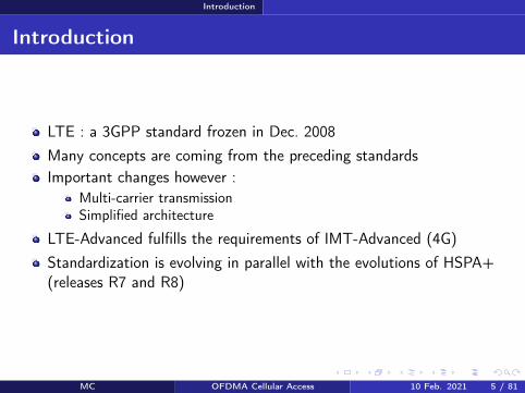
Introduction
Introduction
LTE a 3GPP standard frozen in Dec 2008Many concepts are coming from the preceding standardsImportant changes however
Multi-carrier transmissionSimplified architecture
LTE-Advanced fulfills the requirements of IMT-Advanced (4G)Standardization is evolving in parallel with the evolutions of HSPA+(releases R7 and R8)
MC OFDMA Cellular Access 10 Feb 2021 5 81
Introduction
3GPP standard evolution
Release Date Main evolutions
R99 Mar 2000WCDMAUTRAN radio interfaceATM transport network
R4 Mar 2001 IP in the transport network of UTRANR5 June 2002 HSDPA on the downlinkR6 March 2005 HSUPA on the uplinkR7 Dec 2007 HSPA+ and MIMO techniques
R8 Dec 2008 HSPA+ evolutionsLTE definition
R9 Dec 2009 MBMS for LTE
R10 June 2011 LTE-Advanced definitionCarrier aggregation relays HetNets
R11 Mar 2013 LTE-Advanced further enhancementsCoMP energy saving
R12 Mar 2015LTE-Advanced further enhancementsMachine Type Communications D2Dmission critical communications
R13 Mar 2016 LTE-Advanced ProLicensed Assisted Access 3D beamforming
Table ndash Evolution of 3GPP releases (source httpwww3gpporgspecsreleaseshtm)
MC OFDMA Cellular Access 10 Feb 2021 6 81
How to reduce latency
Section 2
How to reduce latency
MC OFDMA Cellular Access 10 Feb 2021 7 81
How to reduce latency
E-UTRAN architecture I
Answer flat architecture smarter BS and frequent radio resourceallocation (TTI = 1 ms vs 20 ms in UMTS and 2 ms in HSPA)
The radio access network is called Evolved-UTRAN
E-UTRAN = eNodes-B interconnected via X2 interface
E-UTRAN is connected to the Evolved Packet Core (EPC) via S1interface
MC OFDMA Cellular Access 10 Feb 2021 8 81
How to reduce latency
E-UTRAN architecture II
S1
S1S1
S1
X2
X2X2
E-UTRANeNB
eNB
eNB
MMES-GW MMES-GW
Figure ndash E-UTRAN architecture (from [2])
MC OFDMA Cellular Access 10 Feb 2021 9 81
How to reduce latency
E-UTRAN architecture III
Mobility Management Entity (MME) = control plane
Serving Gateway (S-GW) = user planeRNC disappears and the base station (eNB) gets augmentedfonctionalities
PHY and MAC layers (typical since GSM)Fast scheduling and HARQ (like in HSPA)New RLC PDCP RRC
Consequence scheduling retransmissions link adaptation (ie ofdata rates as a function of the radio conditions) and reconfigurationdecisions are taken closer to the radio link
MC OFDMA Cellular Access 10 Feb 2021 10 81
How to reduce latency
Protocol stack I
PDCP
RLC
MAC
PHY
PDCP
RLC
MAC
PHY
UE eNode-B
user plane
control plane
PDCP
RLC
MAC
PHY
PDCP
RLC
MAC
PHY
UE eNode-B
RRC
NAS NAS
MME
RRC
Figure ndash Protocol stack in user and control place of E-UTRAN (from [2])
MC OFDMA Cellular Access 10 Feb 2021 11 81
How to reduce latency
Protocol stack II
PHY RF processingError detection correctionTransmission techniques (multi-carrier modulation MIMO)Synchronization (time frequency)Measurements
MAC Mapping of logical channels to transport channelsMultiplexing demultiplexing of transport channelsFast scheduling every 1 msHARQ retransmissionsRandom accessTiming advanceTransport format selectionPriority management between logical channels
MC OFDMA Cellular Access 10 Feb 2021 12 81
How to reduce latency
Protocol stack IIIRLC
ARQ retransmissions (mode AM)Concatenation segmentation reassembling of RLC SDUsResegmentation of RLC PDUs in case of retransmissionIn sequence delivery of higher layers PDUsDetection of duplicated RLC PDUs
PDCP IP header compression decompression (ROHC)In sequence delivery (RLC AM)Duplicatas detectionRetransmission of PDCP PDUs in case of handover (RLC AM)Cyphering decyphering of data
RRC Radio resource managementMobility managementMeasurements feedbacksRadio bearer control
MC OFDMA Cellular Access 10 Feb 2021 13 81
How to reduce latency
Remember
Network latency Keep this in mind Flat architecture no more RNCE-UTRAN = eNB EPC = MME and SGW X2 and S1 interfacesPHY layer fast scheduling retransmissions in the eNBTTI = 1 ms
MC OFDMA Cellular Access 10 Feb 2021 14 81
How to increase data rates
Section 3
How to increase data rates
MC OFDMA Cellular Access 10 Feb 2021 15 81
How to increase data rates General characteristics of the PHY layer
Context
Remember the Shannon formula C asymp nantW log2(1 + SINR)
In practice however This is a not achieved upper boundThis function is bounded (by Cmax) because we use finite modulationsCapacity should be shared by all active users in the cellSome resources should be dedicated to signaling
To increase data rates we have few options Increase W but issues with inter-symbol interferenceDecrease interference with lower frequency spatial reuse but lessbandwidth per cellIncrease Cmax by densifying the modulation but the signal is moresensitive to noise and interferenceIncrease nant but signal processing algorithm complexity increasesand space is needed for antennasDensify the network in order to decrease the number of users per cellbut more sites = more investments
MC OFDMA Cellular Access 10 Feb 2021 16 81
How to increase data rates General characteristics of the PHY layer
General characteristics I
Spread spectrum is withdrawnMulti-carrier transmission rArr a new organization of radio resourcesOFDMA (DL) SC-FDMA (UL)Possible signal bandwiths 14 3 5 10 15 and 20 MHz (remember 5 MHz in UMTS 2times 5 MHz in HSPA+ with double carrier)Modulations BPSK QPSK 16-QAM 64-QAM (remember QPSKin UMTS 16-QAM in HSPA)64-QAM mandatory for the DL on the UL only cat 5 terminals canuse itConvolutional and turbo convolutional codesDuplexing TDD and FDD
MC OFDMA Cellular Access 10 Feb 2021 17 81
How to increase data rates General characteristics of the PHY layer
General characteristics II
MIMO 2 or 4 Tx 2 or 4 Rx up to 4 parallel flows can be usedMU-MIMO in DL and UL (remember no MIMO in UMTS 2times 2 inHSPA+)
FDD frequency bands around 700 800 1400 1700 1800 19002100 et 2600 MHz (800 1800 2600 MHz in France)
MC OFDMA Cellular Access 10 Feb 2021 18 81
How to increase data rates Multicarrier transmissions
OFDMOFDMA I
OFDM = a transmission techniqueAdvantages partly tackle the multi-path propagation issue highspectral efficiency simple implementation
UEeNode-B
Path 1
Path 2
Path 3
Am
plit
ud
e
Relative delays
wrt path 1Path 1 Path 2 Path 3
Delay spread τmax
Figure ndash Multi-path propagation and maximum delay spread
MC OFDMA Cellular Access 10 Feb 2021 19 81
How to increase data rates Multicarrier transmissions
OFDMOFDMA II
If τmax gt Tsymb rArr Inter-Symbol Interference (ISI)1τmax asymp channel coherence bandwidth1Tsymb asymp signal bandwidthWider is the signal bandwidth higher is the ISIOFDM divides the global bandwidth in small frequency sub-channelsor sub-carriers with bandwidth ∆f 1τmax
ISI is almost completely removed
MC OFDMA Cellular Access 10 Feb 2021 20 81
How to increase data rates Multicarrier transmissions
OFDMOFDMA III
Frequencyf1 f2 f3 Frequencyf1 f2 f3
FDM OFDM
Figure ndash Comparison between OFDM and FDM in terms of spectral efficiency
Higher spectral efficiency than FDMPartial overlapping of the sub-channels thanks to the orthogonalitybetween sub-carriers
MC OFDMA Cellular Access 10 Feb 2021 21 81
How to increase data rates Multicarrier transmissions
OFDMOFDMA IV
times
times
times
times
times
times
TSymb
f1
f2
f3f1 f2 f3
FFT
IFFT
Time domain Frequency domain
Δf=f2-f1=1TSymb
QAM
QAM
QAM
Figure ndash OFDM signal in time and frequency domains
Orthogonality When the signal of sub-carrier n is maximum thesignal of all other sub-carriers is nullOrthogonality is obtained when ∆f = 1TSymb
Time domain The OFDM symbol is the sum of modulatedsub-carriers multiplied by a rectangle (gate) function
MC OFDMA Cellular Access 10 Feb 2021 22 81
How to increase data rates Multicarrier transmissions
OFDMOFDMA V
t
Copy
path 1
path 2
path 3
TSymb
τmax
Tg Tu
Figure ndash Guard intervalcyclic prefix of an OFDM symbol
To completely remove residual ISI one adds a cyclic prefix
MC OFDMA Cellular Access 10 Feb 2021 23 81
How to increase data rates Multicarrier transmissions
OFDMOFDMA VI
SPModulation
QAM IFFTAdd
cyclic
prefixPS
Remove
cyclic
prefixPS
De-
modulation
QAMFFT SP
frequencyDomain
time
System bandwidth ~ N sub-carriers
user bandwidth~ M sub-carriers
f f
1 2
3
4
= QAM symbol1 2
3
4
Transmit antenna
Receive antenna
SP SerialParallel PS ParallelSerial
Figure ndash OFDMOFDMA transmission and reception chains
The OFDM signal is easy to modulate and demodulate
MC OFDMA Cellular Access 10 Feb 2021 24 81
How to increase data rates Multicarrier transmissions
OFDMOFDMA VIIOFDM has two drawbacks (1) Inter-carrier interference (due toimperfect synchronization or strong Doppler effect) and (2) High Peakto Average Ratio (PAPR)
Pmax
Pmoy
Power amplifier input
Am
plifi
er
outp
ut
PmaxPmoy
Saturation
Backoff
Figure ndash Peak to Average Ratio of the OFDM signal
MC OFDMA Cellular Access 10 Feb 2021 25 81
How to increase data rates Multicarrier transmissions
OFDMOFDMA VIII
OFDM = transmission technique
OFDMA = multiple access method based on OFDM
Groups of sub-carriers can be allocated to different users
rArr no intra-cell interference (6= CDMA)
Radio resource allocation in the timefrequency domain
MC OFDMA Cellular Access 10 Feb 2021 26 81
How to increase data rates Multicarrier transmissions
SC-FDMA I
High PAPR rArr an issue for the ULSC-FDMA = Transmission technique with low PAPR for the UL
SPModulation
QAM
IFFTNgtM
points
Add
cyclic
prefixPS
Remove
cyclic
prefixPS
De-
modulation
QAM
FFTNgtM
pointsSP
FFTM
points
0
0000
System bandwidth ~ N sub-carriers
user bandwidth~ M sub-carriers
f
IFFTM
points
0
0000
time frequencyDomain
time
f
1
2
3
4
1
2
3
4
1
2
3
4
1
2
3
4
3 = QAM symbols of a user1 2 4
Transmit antenna
Receive antenna
SP SerialParallel PS ParallelSerial
Figure ndash SC-FDMA transmission and reception chains
MC OFDMA Cellular Access 10 Feb 2021 27 81
How to increase data rates Multicarrier transmissions
SC-FDMA II
The FFT spreads every QAM symbol over M sub-carriers
Every sub-carrier successively carriers all QAM symbols
At a given instant a unique QAM symbol is transmitted
The resulting PAPR is thus the same as for a QAM modulation
The remaining N minusM sub-carriers are available and can be allocatedto other users
MC OFDMA Cellular Access 10 Feb 2021 28 81
How to increase data rates Multicarrier transmissions
LTE configurations I
Configuration ∆f (kHz) Cyclic prefix (micros) Tu (micros)Normal prefix 15 52 (first symbol) 666
47 (other symbols)Extended prefix 15 167 666
Table ndash OFDM parameters on the downlink of LTE
Normal configuration 7 OFDM symbols per slot small prefixduration rArr relatively small cells (cell radius lt 2 Km)Extended configuration higher prefix duration 6 OFDM symbols perslot rArr larger cells (up to 10 Km) and single frequency networks (forbroadcast multicast services)
MC OFDMA Cellular Access 10 Feb 2021 29 81
How to increase data rates Multicarrier transmissions
LTE configurations II
Transmission techniques Keep this in mind OFDM advantages combat and take advantage of multi-pathpropagation high spectral efficiency easy and cheap implementationOFDM drawbacks Inter-carrier interference (ICI) PAPROFDMASC-FDMA are multiple access schemesSC-FDMA advantage A solution for a low PAPR ULSC-FDMA drawback A user can be allocated only a set of contiguoussub-carriersSpectral separation between sub-carriers is constant equal to 15 KHzwhatever the total signal bandwidth
MC OFDMA Cellular Access 10 Feb 2021 30 81
How to increase data rates Multiple antenna techniques
MIMO gains
Diversity gain several independent copies of the signal are availableat the receiver improve the robustness of the signalArray gain transmission side energy is focused in one or severaldirections (beamforming) reception side more energy is captured byseveral antennas improve the SNR may reduce interferencesMultiplexing gain several parallel flows are simultaneouslytransmitted the SISO channel capacity is multiplied by min(MN)where M and N are the number of transmit and receive antennas respTypical configurations 2times 2 and 4times 2 then 4times 4
MC OFDMA Cellular Access 10 Feb 2021 31 81
How to increase data rates Multiple antenna techniques
Transmit diversity (TM2)
SFBCCoding
s2 s1s2
s1
s1
-s2
Figure ndash Transmit diversity
2 or 4 transmit antennasSpace-Time Block Code (SFBC) Alamouti code [4] in the frequencydomainImproves the robustness of the signal without increasing the data rateOpen loopBackup transmission mode for other modes
MC OFDMA Cellular Access 10 Feb 2021 32 81
How to increase data rates Multiple antenna techniques
Spatial multiplexing (TM3 open loop TM4 closed loop)
Pre-coding
flow 1
flow 2
(a) Open loop
Pre-coding
flow 1
flow 2
(b) Closed loop
Figure ndash Spatial multiplexing
Several flows are simultaneously transmitted (2 or 4 antennas)Open loop precoding matrices are known at the receiver and changein a cyclic manner at the transmitterClosed loop the UE feedbacks its preferred precoding matrix thissolution is well adapted to UEs in low mobility
MC OFDMA Cellular Access 10 Feb 2021 33 81
How to increase data rates Multiple antenna techniques
TM5 Multi-user MIMO
eNode-B
(a) DL
eNode-B
(b) UL
eNBtransmitpower
UE2
UE1
UE1
UE2
UE1
UE2
Figure ndash MU-MIMO transmission (a) on the downlink and (b) on the uplink
Two simultaneous flows on a single timefrequency resourceTechnique similar to the spatial multiplexing scheme with closed loop
MC OFDMA Cellular Access 10 Feb 2021 34 81
How to increase data rates Multiple antenna techniques
TM6 and TM7 Beamforming
Node-B
UE
Figure ndash Beamforming
An antenna array is used to create an antenna beam in the directionof the UE rArr increase useful signal power at the receiverPilot signals specific to the UE are required
MC OFDMA Cellular Access 10 Feb 2021 35 81
How to increase data rates Multiple antenna techniques
Remember
MIMO Keep this in mind Transmit diversity improves the signal robustnessSpatial multiplexing increases data rates in good radio conditionsBeamforming increases the useful signal powerOpen loop no feedback from UEs (for fast UEs)Closed loop feedback from UEs (more efficient but for slow UEs)
MC OFDMA Cellular Access 10 Feb 2021 36 81
Radio resource organization Frame Structure
Frame structure (type 1 for FDD)
0 1 2 3 18 19
One radio frame Tf = 307 200 T
s = 10 ms
One sub-frame 30 720 Ts = 1 ms
One slot Tslot
= 15 360 Ts = 05 ms
0 1 2 3 4 5 6
160 2048 144 2048 144 2048 144 2048 144 2048 144 2048 144 2048
One OFDMSC-FDMA symbol = 666 micros
512 2048
0 1 2 3 4 5
Short prefix
Extended(15 kHz)
Figure ndash Frame structure type 1 in LTE FDD for 20 MHz (from [1])
MC OFDMA Cellular Access 10 Feb 2021 37 81
Radio resource organization Reference Signals
Reference signals I
DC (Direct Current)∆f = 15 kHz
2048 sub-carriers
1200 used sub-carrierGuard band Guard band
Pilot sub-carriers(signaux de reacutefeacuterence)
Data sub-carriers
Central frequency
Figure ndash Data pilot (reference signals) and null (carrier frequency and guardbands) sub-carriers on the DL of LTE
Reference signals are required for the channel estimation and thedecoding of user data
MC OFDMA Cellular Access 10 Feb 2021 38 81
Radio resource organization Reference Signals
Reference signals II
Port 0 Port 1 Port 2 Port 3t
f One antenna port
Two antenna ports
Four antenna ports
RE used by this antenna port to transmit a RS
RE free of transmission on this port
RE
0 1 2 3 4 5 6 0 1 2 3 4 5 6
RB
Figure ndash Reference signals (from [1])MC OFDMA Cellular Access 10 Feb 2021 39 81
Radio resource organization Resource elements and blocks
Resource elements (RE) and blocks (RB) I
f
t
Slot (05 ms)
Sub-frame (1 ms)
180 kHz
UE1
UE2
UE3
UE412 s
ub
-carr
iers
of
15 K
Hz
7 OFDMSC-FDMA symbols
RE
RB
Figure ndash Resource Elements and Resource Blocks in LTE in normal configuration
MC OFDMA Cellular Access 10 Feb 2021 40 81
Radio resource organization Resource elements and blocks
Resource elements (RE) and blocks (RB) II
1 RE = 1 sub-carrier times 1 OFDMSC-FDMA symbol
1 RB = 12 sub-carriers times 7 OFDMSC-FDMA symbols
Minimum amount of resource allocated to a UE 2 successive RBs
Parameter Bandwidth (MHz)14 3 5 10 15 20
FFT size 128 256 512 1024 1536 2048Used sub-carriers 72 180 300 600 900 1200
RB 6 15 25 50 75 100
Table ndash Available radio resources vs signal bandwidth (from [3])
MC OFDMA Cellular Access 10 Feb 2021 41 81
Radio resource organization Resource elements and blocks
Remember
Radio resource organization Keep this in mind Radio resources are organized in the time-frequency domain (orslot-sub-carrier)1 radio frame (10 ms) = 10 sub-frames (1 ms) = 20 slots (0 5 ms)1 RE = 1 sub-carriers times 1 symbol1 RB = 12 sub-carriers times 7 symbolsMinimum allocation 2 successive RBs (every 1 ms)20 MHz 100 RB
MC OFDMA Cellular Access 10 Feb 2021 42 81
Radio resource organization Downlink channels
Downlink physical channels
1 2 3 4 6 7 8 9
Radio frame (10 ms)
PBCH
PSSSSS
Sub-frame (1 ms)
SSS PSS
DC
10
8 M
Hz
Slot 0 Slot 1
0 5 6 0 1 2 3 6 0 6 6
PDSCH
PDSCH
1 2 1 2 0
PDCCH1 2 or 3 OFDM symbols
signaled by the PCFICH
PCFICH
A PHICHgroup
Syste
m b
and
wid
th
Figure ndash Mapping of downlink physical channels on the radio frameMC OFDMA Cellular Access 10 Feb 2021 43 81
Radio resource organization Uplink channels
Uplink physical channels I
Time location defined by the PRACH config
f
t
Syste
m b
an
dw
idth
Frame (10 ms)
6R
B6R
B
Frequency locationdefined byhigher layers
PRACH period
1 or 2 frames depending on the PRACH configuration
PUCCH
PUCCH
PUSCH
Figure ndash Position of the PRACH PUSCH and PUCCH in the LTE frame
MC OFDMA Cellular Access 10 Feb 2021 44 81
Radio resource organization Uplink channels
Uplink physical channels II
f
tSlot (05 ms)
0 1 2 3 4 5 6
PUSCH
UE1
UE2
UE3
DM
RS
DM
RS
DM
RS
Figure ndash DMRS during a PUSCH transmission (from [1])
MC OFDMA Cellular Access 10 Feb 2021 45 81
Radio resource organization Uplink channels
Transport and logical channels
Transport channels
Control informations
Physical channels
Uplink Downlink
RACH UL-SCH
UCI
PRACH PUSCH PUCCH
DL-SCH
DCI
PDSCH PDCCH
CFI
PCFICH
HI
PHICH
PCH BCH
PBCH
MCH
PMCH
CCCH
Logical channels
DTCH
DCCH
PCCH DTCH
DCCH
BCCH MCCH MTCHCCCH
Figure ndash Mapping of physical transport and logical channels
MC OFDMA Cellular Access 10 Feb 2021 46 81
How to synchronize
Section 5
How to synchronize
MC OFDMA Cellular Access 10 Feb 2021 47 81
How to synchronize Objectifs
Objectives
Objectives time and frequency PCI (Physical Cell Identifier) andSystem Informations acquisitionPCI 504 identities classified in 168 groups of 3System Informations network identity common channelsconfiguration selectionreselectionhandover parameters informationson neighbor cells They are organized in one MIB (Master InformationBlock) and several SIBs (System Information Block)
MC OFDMA Cellular Access 10 Feb 2021 48 81
How to synchronize Cell search
Cell search I
1 Find the most powerful carrier in the operator spectrum2 PSS decoding (62 sub-carrier in the middle of the band whatever the
bandwidth) rArr the PSS broadcasts a sequence among 33 SSS decoding rArr the SSS broadcasts 2 pseudo-random sequences of
62 bits on slots 0 and 10 there are 168 possible pairs4 Radio quality evaluation using RSs rArr the UE is synchronized if the
quality is sufficient the transmitted sequence and the position of theRSs in the frame depend on the PCI so that RSs from neighboringcells do not interfere
MC OFDMA Cellular Access 10 Feb 2021 49 81
How to synchronize Cell search
Cell search II
5 PBCH decoding rArr MIB (Master Information Block) antennaconfiguration the position of the PBCH does not depend on thebandwidth it is scrambled by a sequence that depends on the PCIThe MIB includes
the bandwidth (in of RBs)PHICH parametersthe frame number
6 PCFICH decoding rArr Number of OFDM symbols dedicated toPDCCHs
7 PDCCH decoding rArr DCI message (with SI-RNTI address) givingthe location of the SIB1 in the PDSCH
8 SIB1 decoding rArr scheduling of other SIBs
9 SIBs (System Information Block) are received on the PDSCH
MC OFDMA Cellular Access 10 Feb 2021 50 81
How to access the network
Section 6
How to access the network
MC OFDMA Cellular Access 10 Feb 2021 51 81
How to access the network Objectives
Objectives
Objectives Establishment or re-establishment of the RRC connectionIntra-system handoversUpon arrival of DL or UL data whereas the UE has lost itssynchronization with the network
2 random access types contention-based conflict-freeContention-based access can be used in all casesConflict-free access for handovers or upon arrival of DL data
PRACH transmission on the uplink then transmission of a CCCHmessage signaling the reason of the access
MC OFDMA Cellular Access 10 Feb 2021 52 81
How to access the network Random access
Contention-based access I
System Information (DL-SCH)(PRACH config PRACH location preamble format sequence list)
Random Access Preamble (RACH)(size of the L2L3 message)
Random Access Response (DL-SCH)(RA-RNTITA temp C-RNTI UL allocation)
CCCH message (UL-SCH)
Collision resolution (DL-SCH)(SDU CCCH)
UEeNB
Figure ndash Contention-based access in LTE
MC OFDMA Cellular Access 10 Feb 2021 53 81
How to access the network Random access
Contention-based access II1) The UE obtains from SIB the PRACH configuration the PRACH
frequency location the preamble format the target received powerand the list of sequences to be used (64 Zadoff-Chu sequencesincluding those reserved to the conflict-free access)
3) The UE chooses at random one sequence among those available4) It sends the preamble on the PRACH with an open loop power
control the UE tries to compensate the path-loss by usingmeasurements made on DL RSs rArr power control makes sequencedetection easier at the BS
Collision several UEs have used the same sequence on the same radioresourceCapture the eNB manages to decode one of the messages in collision
MC OFDMA Cellular Access 10 Feb 2021 54 81
How to access the network Random access
Contention-based access III
5) If there is no answer from the network power ramping (like inCDMA) ie the UE stepwise increases its transmit power
6) The RAR identifies the decoded preamble + provides the timingadvance (TA) + gives an UL allocation + a temporary identity(temporary C-RNTI address)
7) CCCH message on the PUSCH = eg a RRC connection request +temporary C-RNTI
8) Collision resolution the eNB sends a copy of the CCCH message onthe DL The UE that recognizes its message adopts the temporaryC-RNTI (now its address) other UEs leave the procedure
MC OFDMA Cellular Access 10 Feb 2021 55 81
How to access the network Random access
Conflict-free access
The UE has a valid identity (C-RNTI)The eNB sends a (DCI) message on the PDCCH including theZadoff-Chu sequence to be usedCollisions are no more possible no collision resolution phase
MC OFDMA Cellular Access 10 Feb 2021 56 81
How to send and receive data
Section 7
How to send and receive data
MC OFDMA Cellular Access 10 Feb 2021 57 81
How to send and receive data Objectives
Objectives
Objectives Resource allocation tell UEs on which radio resources they will receivedata on the DL-SCH or on which resource they are allowed to transmiton the UL-SCHUE scheduling allocate RBs to UEs as a function of their demand andtheir radio conditionsError control ARQ and HARQ retransmissionsMeasurement feedbacks the UE tells the network the downlinkchannel radio quality or its preferred MIMO precoding matrix
MC OFDMA Cellular Access 10 Feb 2021 58 81
How to send and receive data Resource allocation
Resource allocation I
Location of resources in the sub-frame modulation and coding schemeare signaled in Downlink Control Information (DCI) messagestransmitted on the PDCCHs
Format Description0 Resource allocation on the PUSCH1 PDSCH resource allocation in TM1 TM2 TM71A PDSCH compact allocation and PRACH signature1B PDSCH resource allocation in TM61C PDSCH very compact allocation1D PDSCH compact allocation in TM52 PDSCH compact allocation in TM42A PDSCH compact allocation in TM33 Power control on PUCCHPUSCH (2 bits)3A Power control on PUCCHPUSCH (1 bit)
Table ndash DCI formats
MC OFDMA Cellular Access 10 Feb 2021 59 81
How to send and receive data Resource allocation
Resource allocation II
DCI 0 example A flag to differentiate 1 and 1AA flag for frequency hopping on the PUSCHResource block allocationModulation and coding scheme redundancy version for HARQHARQ new transmission indicatorA power control command for the ULCyclic shift to be applied to ZC sequence for DMRSA CQI request
Every DCI includes a CRC scrambled with a RNTI identityC-RNTI = to address a unique UEP-RNTI = paging messageSI-RNTI = SIBRA-RNTI = random access response
MC OFDMA Cellular Access 10 Feb 2021 60 81
How to send and receive data Scheduling
Scheduling I
Fast (every 1 ms) and adaptive (modulation and coding are adaptedto radio conditions) schedulingDL scheduling decisions are based on CQI feedbacks buffer statusand priorities between logical channelsUL the UE has to feedback its buffer status and radio resource needsby using either the PUCCH (scheduling request) or the UL-SCH (MACcontrol messages)
MC OFDMA Cellular Access 10 Feb 2021 61 81
How to send and receive data Scheduling
Scheduling IIAlgorithm LTE offers a new degree of freedom wrt HSPA thepossibility to schedule users on different radio blocks
Channel q
ualit
y
fPRB1 PRB2 PRB3 PRB4 PRB5
Channel UE1
Channel UE2
Channel UE3
Scheduling decisions UE2 UE3 UE1 UE3 UE2
Figure ndash Frequency Dependent Packet Scheduling (FDPS) in LTE
MC OFDMA Cellular Access 10 Feb 2021 62 81
How to send and receive data Scheduling
Scheduling III
f
t
Syste
m b
an
dw
idth
Sub-frame (1 ms)
f
t
Comb onesub-carrieris used outof two
(a) SRS transmission without frequency hopping
(b) SRS transmission with frequency hopping
Figure ndash Sounding Reference Signals (SRS) transmissions
The eNB estimates the channel quality on the UL thanks to SRS
SRS is transmitted on a bandwidth much larger than the one allocated to UEtransmissions
SRS from different UEs are multiplexed in time (different sub-frames and periods)frequency (different sets of RBs oddeven sub-carriers) or code (differentsequences)
MC OFDMA Cellular Access 10 Feb 2021 63 81
How to send and receive data Error control
ARQ and HARQ
Like in HSPA HARQ is in the MAC layer and ARQ in the RLCHARQ DL sequence number is signaled in the PDCCH ACKNACKare fed back in the PUSCH (with data) or in the PUCCHHARQ UL ACKNACK transmitted in the PHICHARQ Transparent Mode (TM) (no header no segmentation orconcatenation) Unacknowledged (UM) (header with sequencenumber) Acknowledged (AM) (ARQ)
MC OFDMA Cellular Access 10 Feb 2021 64 81
How to send and receive data Measurements
Measurements
Radio quality measurements CQI (Channel Quality Indicator) modulation (QPSK 16-QAM or64-QAM) and transport block maximum size that a UE can receivewith a BLERlt10 (Block Error Rate)RI (Rank Indicator) rank of the DL transmission = number ofindependent spatial layers that can be usedPMI (Precoding Matrix Indicator) UE preferred precoding matrix Wfor transmission modes with closed loop
Physical channels PUSCH for aperiodic feedbacks with data transmissionPUCCH for periodic feedbacks
MC OFDMA Cellular Access 10 Feb 2021 65 81
Terminals categories
Section 8
Terminals categories
MC OFDMA Cellular Access 10 Feb 2021 66 81
Terminals categories
Terminals categories
Caracteristics Cat 1 Cat 2 Cat 3 Cat 4 Cat 5Max number ofbits per TTI (DL) 10296 51024 102048 150752 299552
Max number ofbits per TTI (UL) 5160 25456 51024 51024 75376
Max data rate(DL) 10 Mbps 50 Mbps 100 Mbps 150 Mbps 300 Mbps
Max data rate(UL) 5 Mbps 25 Mbps 50 Mbps 50 Mbps 75 Mbps
64 QAM (UL) No No No No YesMIMO (DL) Option 2times 2 2times 2 2times 2 4times 4
Table ndash Terminal categories in LTE
For example the Semsong S5 is cat 4 the Semsong S6 is cat 6 (Release 1030050 Mbps) the Semsong S8 is cat1613 (Release 12 1050150 Mbps MIMO4x4 256-QAM 5CA) Semsong S10 is cat 2013 (2000 Mbps up to 8 MIMOlayers 256-QAM 7CA)
MC OFDMA Cellular Access 10 Feb 2021 67 81
Summary on channels
Section 9
Summary on channels
MC OFDMA Cellular Access 10 Feb 2021 68 81
Summary on channels
Physical channels DL I
PDSCH (Physical Downlink Shared Ch) physical shared channel for data
RS (Reference Signals) pilots required to estimate radio quality and toallow decoding on the DL
SS (Synchronization Signals) = PSS (Primary)+SSS (Secondary) for timeand frequency synchronization
PBCH (Physical Broadcast Ch) beacon MIB transmission
PCFICH (Physical Control Format Indicator Ch) tell the UEs how manyOFDM symbols are dedicated to the control part of the sub-frame (CFI)
PDCCH (Physical Downlink Control Ch) control informations (DCI resource allocation UE identity HARQ information MIMO etc)
PHICH (Physical Hybrid ARQ Indicator Ch) ACKNACK responses toHARQ transmissions from a UE (HI)
MC OFDMA Cellular Access 10 Feb 2021 69 81
Summary on channels
Physical channels UL I
In UL a UE is not able to multiplex different physical channels in the frequencydomain because of SC-FDMA limitation rArr time multiplexing is required
DMRS (Demodulation Reference Signal) used by the eNB to estimate thechannel and make radio quality measurements on the signal transmitted by theUE DMRS are sent in conjunction with PUCCH and PUSCH
SRS (Sounding Reference Signal) pilots used by the scheduler for the radioquality estimation on a bandwidth larger than the one allocated to the UE
PUCCH (Physical Uplink Control Ch) control informations UCI includingchannel quality (CQI) MIMO (closed loop) or HARQ (ACKNACK) informations
PUSCH (Physical Uplink Shared Ch) shared physical channels for data andcontrol
If a UE has data to transmit it uses the PUSCH for data and control Otherwiseit uses the PUCCH for the control
MC OFDMA Cellular Access 10 Feb 2021 70 81
Summary on channels
Transport channels DL
DL-SCH (DL Shared Ch) shared channel for data associated toPDSCHPCH (Paging Ch) broadcast of paging messages on the PDSCHBCH (Broadcast Ch) broadcast of system informations (SIBs) onthe PBCH and on the PDSCHDCI (DL Control Indicator) control information transmitted on thePDCCHs (transport format resource allocation HARQ and MIMOinformations power control commands)CFI (Control Format Indicator) number of OFDM symbols (12 or 3)used by PDCCHs at the beginning of every sub-frame CFI is sent onthe PCFICHHI (HARQ Indicator) ACK or NACK in response to a transmissionon the UL-SCH HI is transmitted on the PHICH
MC OFDMA Cellular Access 10 Feb 2021 71 81
Summary on channels
transport channels UL
RACH (Random Access Ch) random accessUL-SCH (UL Share Ch) shared channel for data and controlassociated to PUSCH User data and control informations aremultiplexed in time and frequency on the PUSCHUCI (UL Control Indicator) control information transmitted by thePUCCH (channel quality CQI closed loop MIMO informationsPMIRI ACKNACK of HARQ scheduling request)
MC OFDMA Cellular Access 10 Feb 2021 72 81
Summary on channels
Logical channels
Logical channel Type Description LinkBCCH Control System information DLPCCH Control Paging DLCCCH Control Control without RRC conn ULDLDCCH Controcircle Dedicated control ULDLDTCH Traffic user plane ULDL
Table ndash Logical channels in LTE DL and UL
BCCH (Broadcast COntrol Ch) system information associated to BCH for theMIB and DL-SCH for the SIBs
PCCH (Paging Control Ch) paging associated to PCH
CCCH (Common Control Ch) control messages between the network and UEswithout RRC connection associated to DL-SCH and UL-SCH
DCCH (Dedicated Control Ch) control messages between the network and UEswith RRC connection associated to DL-SCH and UL-SCH
MC OFDMA Cellular Access 10 Feb 2021 73 81
Conclusion
Section 10
Conclusion
MC OFDMA Cellular Access 10 Feb 2021 74 81
Conclusion
Conclusion
LTE A brand new standardA certain simplicity that is reminiscent of GSMSimilarities with 3G (channels HARQ MAC RLC etc)New features (MIMO MU-MIMO multi-carrier transmissions)
After LTE LTE-A R13 frozen in Mar 2016 (LTE Pro) R14 on goingR15 is called 5G New Radio (NR) and is the first 5G releasePeak rates of the order of 1GbpsCarrier aggregation discontinuous resource allocation on the ULMIMO 8times8 relays HetNets CoMP Self-Organized NetworksMBMS NB-IoT etc
MC OFDMA Cellular Access 10 Feb 2021 75 81
Conclusion
References I
3GPPTechnical Specification 36211 Physical channels and modulationDec 2009
3GPPTechnical Specification 36300 Evolved Universal Terrestrial RadioAccess (E-UTRA) and Evolved Universal Terrestrial Radio AccessNetwork (E-UTRAN) Overall description Apr 2010
3GPPTechnical Specification 36104 Base Station (BS) radio transmissionand reception Jun 2011
MC OFDMA Cellular Access 10 Feb 2021 76 81
Conclusion
References II
S M AlamoutiA simple transmit diversity technique for wireless communicationsIEEE J on Selected Areas in Communications 16(8) 1451ndash1458 Oct1998
MC OFDMA Cellular Access 10 Feb 2021 77 81
Conclusion
Acronyms I
AM ARQ Acknowledged ModeARQ Automatic Repeat on RequestBCCH Broadcast Control ChannelBCH Broadcast ChannelBLER Block Error RateBPSK Binary Phase Shift KeyingBS Base Station
CCCH Common Control ChannelCDMA Code Division Multiple AccessCFI Control Format Indocator
CoMP Coordinated Multi-PointCQI Channel Quality IndicatorCRC Cyclic Redundancy CodeD2D Device to DeviceDCCH Dedicated Control ChannelDCI Downlink Control InformationDL Downlink
DL-SCH Downlink Shared ChannelDMRS Demodulation Reference SignalDTCH Dedicated Traffic ChanneleNB eNode-BEPC Evolved Packet Core
E-UTRAN Evolved UTRANFDD Frequency Division DuplexFDPS Frequency Dependent Packet SchedulingFFT Fast Fourier TransformGSM Groupe Speacutecial MobileHARQ Hybrid Automatic Repeat on Request
MC OFDMA Cellular Access 10 Feb 2021 78 81
Conclusion
Acronyms IIHI HARQ Indicator
HSPA High Speed Packet AccessHSDPA High Speed Downlink Packet AccessHSPA High Speed Uplink Packet AccessICI Inter-Carrier InterferenceIFFT Inverse Fast Fourier TransformIMT International Mobile TelecommunicationsISI Inter-Symbol InterferenceLTE Long Term EvolutionMAC Medium Access ControlMBMS Multimedia Broadcast Multicast ServiceMIB Master Information BlockMIMO Multiple Input Multiple OutputMME Mobility Management Entity
MU-MIMO Multi-User MIMONAS Non Access StratumOFDM Orthogonal Frequency Division MultiplexOFDMA Orthogonal Frequency Division Multiple AccessPAPR Peak to Average Power RatioPBCH Physical Broadcast ChannelPCFICH Physical Control Format Indicator ChannelPCCH Paging Control ChannelPCH Paging ChannelPCI Physical Cell Identifier
PDCCH Physical Downlink Control ChannelPDCP Packet Data Convergence ProtocolPDSCH Physical Downlink Shared ChannelPDU Protocol Data Unit
MC OFDMA Cellular Access 10 Feb 2021 79 81
Conclusion
Acronyms IIIPHICH Physical Hybrid ARQ Indicator ChannelPMI Precoding Matrix IndicatorPSS Primary Synchronization Signal
PUCCH Physical Uplink Control ChannelPUSCH Physical Uplink Shared ChannelQAM Qadrature Amplitude ModulationQPSK Quadrature Phase Shift KeyingRACH Random Access ChannelRAR Random Access ResponseRB Resource BlockRE Resource ElementRI Rank IndicatorRLC Radio Link ControlRNC Radio Network ControllerRNTI Radio Network Temporary IdentifierROHC Robust Header CompressionRRC Radio Resource ControlRS Reference Signal
SC-FDMA Single Carrier Frequency Division Multiple AccessSDU Service Data UnitSFBC Space-Time Block CodeSGW Serving GatewaySIB System Information BlockSISO Single Input Single OutputSNR Signal to Noise RatioSRS Sounding Reference SignalSSS Secondary Synchronization SignalTA Timing Advance
MC OFDMA Cellular Access 10 Feb 2021 80 81
Conclusion
Acronyms IV
TDD Time Division DuplexTM Transmission ModeTM ARQ Transparent ModeTTI Transmission Time IntervalUCI Uplink Control InformationUE User EquipmentUM ARQ Unacknowledged Mode
UMTS Universal Mobile Telecommunications SystemUL Uplink
UL-SCH Uplink Shared ChannelUTRAN UMTS Terrestrial Radio Access NetworkWCDMA Wideband Code Division Multiple Access
MC OFDMA Cellular Access 10 Feb 2021 81 81

Introduction
3GPP standard evolution
Release Date Main evolutions
R99 Mar 2000WCDMAUTRAN radio interfaceATM transport network
R4 Mar 2001 IP in the transport network of UTRANR5 June 2002 HSDPA on the downlinkR6 March 2005 HSUPA on the uplinkR7 Dec 2007 HSPA+ and MIMO techniques
R8 Dec 2008 HSPA+ evolutionsLTE definition
R9 Dec 2009 MBMS for LTE
R10 June 2011 LTE-Advanced definitionCarrier aggregation relays HetNets
R11 Mar 2013 LTE-Advanced further enhancementsCoMP energy saving
R12 Mar 2015LTE-Advanced further enhancementsMachine Type Communications D2Dmission critical communications
R13 Mar 2016 LTE-Advanced ProLicensed Assisted Access 3D beamforming
Table ndash Evolution of 3GPP releases (source httpwww3gpporgspecsreleaseshtm)
MC OFDMA Cellular Access 10 Feb 2021 6 81
How to reduce latency
Section 2
How to reduce latency
MC OFDMA Cellular Access 10 Feb 2021 7 81
How to reduce latency
E-UTRAN architecture I
Answer flat architecture smarter BS and frequent radio resourceallocation (TTI = 1 ms vs 20 ms in UMTS and 2 ms in HSPA)
The radio access network is called Evolved-UTRAN
E-UTRAN = eNodes-B interconnected via X2 interface
E-UTRAN is connected to the Evolved Packet Core (EPC) via S1interface
MC OFDMA Cellular Access 10 Feb 2021 8 81
How to reduce latency
E-UTRAN architecture II
S1
S1S1
S1
X2
X2X2
E-UTRANeNB
eNB
eNB
MMES-GW MMES-GW
Figure ndash E-UTRAN architecture (from [2])
MC OFDMA Cellular Access 10 Feb 2021 9 81
How to reduce latency
E-UTRAN architecture III
Mobility Management Entity (MME) = control plane
Serving Gateway (S-GW) = user planeRNC disappears and the base station (eNB) gets augmentedfonctionalities
PHY and MAC layers (typical since GSM)Fast scheduling and HARQ (like in HSPA)New RLC PDCP RRC
Consequence scheduling retransmissions link adaptation (ie ofdata rates as a function of the radio conditions) and reconfigurationdecisions are taken closer to the radio link
MC OFDMA Cellular Access 10 Feb 2021 10 81
How to reduce latency
Protocol stack I
PDCP
RLC
MAC
PHY
PDCP
RLC
MAC
PHY
UE eNode-B
user plane
control plane
PDCP
RLC
MAC
PHY
PDCP
RLC
MAC
PHY
UE eNode-B
RRC
NAS NAS
MME
RRC
Figure ndash Protocol stack in user and control place of E-UTRAN (from [2])
MC OFDMA Cellular Access 10 Feb 2021 11 81
How to reduce latency
Protocol stack II
PHY RF processingError detection correctionTransmission techniques (multi-carrier modulation MIMO)Synchronization (time frequency)Measurements
MAC Mapping of logical channels to transport channelsMultiplexing demultiplexing of transport channelsFast scheduling every 1 msHARQ retransmissionsRandom accessTiming advanceTransport format selectionPriority management between logical channels
MC OFDMA Cellular Access 10 Feb 2021 12 81
How to reduce latency
Protocol stack IIIRLC
ARQ retransmissions (mode AM)Concatenation segmentation reassembling of RLC SDUsResegmentation of RLC PDUs in case of retransmissionIn sequence delivery of higher layers PDUsDetection of duplicated RLC PDUs
PDCP IP header compression decompression (ROHC)In sequence delivery (RLC AM)Duplicatas detectionRetransmission of PDCP PDUs in case of handover (RLC AM)Cyphering decyphering of data
RRC Radio resource managementMobility managementMeasurements feedbacksRadio bearer control
MC OFDMA Cellular Access 10 Feb 2021 13 81
How to reduce latency
Remember
Network latency Keep this in mind Flat architecture no more RNCE-UTRAN = eNB EPC = MME and SGW X2 and S1 interfacesPHY layer fast scheduling retransmissions in the eNBTTI = 1 ms
MC OFDMA Cellular Access 10 Feb 2021 14 81
How to increase data rates
Section 3
How to increase data rates
MC OFDMA Cellular Access 10 Feb 2021 15 81
How to increase data rates General characteristics of the PHY layer
Context
Remember the Shannon formula C asymp nantW log2(1 + SINR)
In practice however This is a not achieved upper boundThis function is bounded (by Cmax) because we use finite modulationsCapacity should be shared by all active users in the cellSome resources should be dedicated to signaling
To increase data rates we have few options Increase W but issues with inter-symbol interferenceDecrease interference with lower frequency spatial reuse but lessbandwidth per cellIncrease Cmax by densifying the modulation but the signal is moresensitive to noise and interferenceIncrease nant but signal processing algorithm complexity increasesand space is needed for antennasDensify the network in order to decrease the number of users per cellbut more sites = more investments
MC OFDMA Cellular Access 10 Feb 2021 16 81
How to increase data rates General characteristics of the PHY layer
General characteristics I
Spread spectrum is withdrawnMulti-carrier transmission rArr a new organization of radio resourcesOFDMA (DL) SC-FDMA (UL)Possible signal bandwiths 14 3 5 10 15 and 20 MHz (remember 5 MHz in UMTS 2times 5 MHz in HSPA+ with double carrier)Modulations BPSK QPSK 16-QAM 64-QAM (remember QPSKin UMTS 16-QAM in HSPA)64-QAM mandatory for the DL on the UL only cat 5 terminals canuse itConvolutional and turbo convolutional codesDuplexing TDD and FDD
MC OFDMA Cellular Access 10 Feb 2021 17 81
How to increase data rates General characteristics of the PHY layer
General characteristics II
MIMO 2 or 4 Tx 2 or 4 Rx up to 4 parallel flows can be usedMU-MIMO in DL and UL (remember no MIMO in UMTS 2times 2 inHSPA+)
FDD frequency bands around 700 800 1400 1700 1800 19002100 et 2600 MHz (800 1800 2600 MHz in France)
MC OFDMA Cellular Access 10 Feb 2021 18 81
How to increase data rates Multicarrier transmissions
OFDMOFDMA I
OFDM = a transmission techniqueAdvantages partly tackle the multi-path propagation issue highspectral efficiency simple implementation
UEeNode-B
Path 1
Path 2
Path 3
Am
plit
ud
e
Relative delays
wrt path 1Path 1 Path 2 Path 3
Delay spread τmax
Figure ndash Multi-path propagation and maximum delay spread
MC OFDMA Cellular Access 10 Feb 2021 19 81
How to increase data rates Multicarrier transmissions
OFDMOFDMA II
If τmax gt Tsymb rArr Inter-Symbol Interference (ISI)1τmax asymp channel coherence bandwidth1Tsymb asymp signal bandwidthWider is the signal bandwidth higher is the ISIOFDM divides the global bandwidth in small frequency sub-channelsor sub-carriers with bandwidth ∆f 1τmax
ISI is almost completely removed
MC OFDMA Cellular Access 10 Feb 2021 20 81
How to increase data rates Multicarrier transmissions
OFDMOFDMA III
Frequencyf1 f2 f3 Frequencyf1 f2 f3
FDM OFDM
Figure ndash Comparison between OFDM and FDM in terms of spectral efficiency
Higher spectral efficiency than FDMPartial overlapping of the sub-channels thanks to the orthogonalitybetween sub-carriers
MC OFDMA Cellular Access 10 Feb 2021 21 81
How to increase data rates Multicarrier transmissions
OFDMOFDMA IV
times
times
times
times
times
times
TSymb
f1
f2
f3f1 f2 f3
FFT
IFFT
Time domain Frequency domain
Δf=f2-f1=1TSymb
QAM
QAM
QAM
Figure ndash OFDM signal in time and frequency domains
Orthogonality When the signal of sub-carrier n is maximum thesignal of all other sub-carriers is nullOrthogonality is obtained when ∆f = 1TSymb
Time domain The OFDM symbol is the sum of modulatedsub-carriers multiplied by a rectangle (gate) function
MC OFDMA Cellular Access 10 Feb 2021 22 81
How to increase data rates Multicarrier transmissions
OFDMOFDMA V
t
Copy
path 1
path 2
path 3
TSymb
τmax
Tg Tu
Figure ndash Guard intervalcyclic prefix of an OFDM symbol
To completely remove residual ISI one adds a cyclic prefix
MC OFDMA Cellular Access 10 Feb 2021 23 81
How to increase data rates Multicarrier transmissions
OFDMOFDMA VI
SPModulation
QAM IFFTAdd
cyclic
prefixPS
Remove
cyclic
prefixPS
De-
modulation
QAMFFT SP
frequencyDomain
time
System bandwidth ~ N sub-carriers
user bandwidth~ M sub-carriers
f f
1 2
3
4
= QAM symbol1 2
3
4
Transmit antenna
Receive antenna
SP SerialParallel PS ParallelSerial
Figure ndash OFDMOFDMA transmission and reception chains
The OFDM signal is easy to modulate and demodulate
MC OFDMA Cellular Access 10 Feb 2021 24 81
How to increase data rates Multicarrier transmissions
OFDMOFDMA VIIOFDM has two drawbacks (1) Inter-carrier interference (due toimperfect synchronization or strong Doppler effect) and (2) High Peakto Average Ratio (PAPR)
Pmax
Pmoy
Power amplifier input
Am
plifi
er
outp
ut
PmaxPmoy
Saturation
Backoff
Figure ndash Peak to Average Ratio of the OFDM signal
MC OFDMA Cellular Access 10 Feb 2021 25 81
How to increase data rates Multicarrier transmissions
OFDMOFDMA VIII
OFDM = transmission technique
OFDMA = multiple access method based on OFDM
Groups of sub-carriers can be allocated to different users
rArr no intra-cell interference (6= CDMA)
Radio resource allocation in the timefrequency domain
MC OFDMA Cellular Access 10 Feb 2021 26 81
How to increase data rates Multicarrier transmissions
SC-FDMA I
High PAPR rArr an issue for the ULSC-FDMA = Transmission technique with low PAPR for the UL
SPModulation
QAM
IFFTNgtM
points
Add
cyclic
prefixPS
Remove
cyclic
prefixPS
De-
modulation
QAM
FFTNgtM
pointsSP
FFTM
points
0
0000
System bandwidth ~ N sub-carriers
user bandwidth~ M sub-carriers
f
IFFTM
points
0
0000
time frequencyDomain
time
f
1
2
3
4
1
2
3
4
1
2
3
4
1
2
3
4
3 = QAM symbols of a user1 2 4
Transmit antenna
Receive antenna
SP SerialParallel PS ParallelSerial
Figure ndash SC-FDMA transmission and reception chains
MC OFDMA Cellular Access 10 Feb 2021 27 81
How to increase data rates Multicarrier transmissions
SC-FDMA II
The FFT spreads every QAM symbol over M sub-carriers
Every sub-carrier successively carriers all QAM symbols
At a given instant a unique QAM symbol is transmitted
The resulting PAPR is thus the same as for a QAM modulation
The remaining N minusM sub-carriers are available and can be allocatedto other users
MC OFDMA Cellular Access 10 Feb 2021 28 81
How to increase data rates Multicarrier transmissions
LTE configurations I
Configuration ∆f (kHz) Cyclic prefix (micros) Tu (micros)Normal prefix 15 52 (first symbol) 666
47 (other symbols)Extended prefix 15 167 666
Table ndash OFDM parameters on the downlink of LTE
Normal configuration 7 OFDM symbols per slot small prefixduration rArr relatively small cells (cell radius lt 2 Km)Extended configuration higher prefix duration 6 OFDM symbols perslot rArr larger cells (up to 10 Km) and single frequency networks (forbroadcast multicast services)
MC OFDMA Cellular Access 10 Feb 2021 29 81
How to increase data rates Multicarrier transmissions
LTE configurations II
Transmission techniques Keep this in mind OFDM advantages combat and take advantage of multi-pathpropagation high spectral efficiency easy and cheap implementationOFDM drawbacks Inter-carrier interference (ICI) PAPROFDMASC-FDMA are multiple access schemesSC-FDMA advantage A solution for a low PAPR ULSC-FDMA drawback A user can be allocated only a set of contiguoussub-carriersSpectral separation between sub-carriers is constant equal to 15 KHzwhatever the total signal bandwidth
MC OFDMA Cellular Access 10 Feb 2021 30 81
How to increase data rates Multiple antenna techniques
MIMO gains
Diversity gain several independent copies of the signal are availableat the receiver improve the robustness of the signalArray gain transmission side energy is focused in one or severaldirections (beamforming) reception side more energy is captured byseveral antennas improve the SNR may reduce interferencesMultiplexing gain several parallel flows are simultaneouslytransmitted the SISO channel capacity is multiplied by min(MN)where M and N are the number of transmit and receive antennas respTypical configurations 2times 2 and 4times 2 then 4times 4
MC OFDMA Cellular Access 10 Feb 2021 31 81
How to increase data rates Multiple antenna techniques
Transmit diversity (TM2)
SFBCCoding
s2 s1s2
s1
s1
-s2
Figure ndash Transmit diversity
2 or 4 transmit antennasSpace-Time Block Code (SFBC) Alamouti code [4] in the frequencydomainImproves the robustness of the signal without increasing the data rateOpen loopBackup transmission mode for other modes
MC OFDMA Cellular Access 10 Feb 2021 32 81
How to increase data rates Multiple antenna techniques
Spatial multiplexing (TM3 open loop TM4 closed loop)
Pre-coding
flow 1
flow 2
(a) Open loop
Pre-coding
flow 1
flow 2
(b) Closed loop
Figure ndash Spatial multiplexing
Several flows are simultaneously transmitted (2 or 4 antennas)Open loop precoding matrices are known at the receiver and changein a cyclic manner at the transmitterClosed loop the UE feedbacks its preferred precoding matrix thissolution is well adapted to UEs in low mobility
MC OFDMA Cellular Access 10 Feb 2021 33 81
How to increase data rates Multiple antenna techniques
TM5 Multi-user MIMO
eNode-B
(a) DL
eNode-B
(b) UL
eNBtransmitpower
UE2
UE1
UE1
UE2
UE1
UE2
Figure ndash MU-MIMO transmission (a) on the downlink and (b) on the uplink
Two simultaneous flows on a single timefrequency resourceTechnique similar to the spatial multiplexing scheme with closed loop
MC OFDMA Cellular Access 10 Feb 2021 34 81
How to increase data rates Multiple antenna techniques
TM6 and TM7 Beamforming
Node-B
UE
Figure ndash Beamforming
An antenna array is used to create an antenna beam in the directionof the UE rArr increase useful signal power at the receiverPilot signals specific to the UE are required
MC OFDMA Cellular Access 10 Feb 2021 35 81
How to increase data rates Multiple antenna techniques
Remember
MIMO Keep this in mind Transmit diversity improves the signal robustnessSpatial multiplexing increases data rates in good radio conditionsBeamforming increases the useful signal powerOpen loop no feedback from UEs (for fast UEs)Closed loop feedback from UEs (more efficient but for slow UEs)
MC OFDMA Cellular Access 10 Feb 2021 36 81
Radio resource organization Frame Structure
Frame structure (type 1 for FDD)
0 1 2 3 18 19
One radio frame Tf = 307 200 T
s = 10 ms
One sub-frame 30 720 Ts = 1 ms
One slot Tslot
= 15 360 Ts = 05 ms
0 1 2 3 4 5 6
160 2048 144 2048 144 2048 144 2048 144 2048 144 2048 144 2048
One OFDMSC-FDMA symbol = 666 micros
512 2048
0 1 2 3 4 5
Short prefix
Extended(15 kHz)
Figure ndash Frame structure type 1 in LTE FDD for 20 MHz (from [1])
MC OFDMA Cellular Access 10 Feb 2021 37 81
Radio resource organization Reference Signals
Reference signals I
DC (Direct Current)∆f = 15 kHz
2048 sub-carriers
1200 used sub-carrierGuard band Guard band
Pilot sub-carriers(signaux de reacutefeacuterence)
Data sub-carriers
Central frequency
Figure ndash Data pilot (reference signals) and null (carrier frequency and guardbands) sub-carriers on the DL of LTE
Reference signals are required for the channel estimation and thedecoding of user data
MC OFDMA Cellular Access 10 Feb 2021 38 81
Radio resource organization Reference Signals
Reference signals II
Port 0 Port 1 Port 2 Port 3t
f One antenna port
Two antenna ports
Four antenna ports
RE used by this antenna port to transmit a RS
RE free of transmission on this port
RE
0 1 2 3 4 5 6 0 1 2 3 4 5 6
RB
Figure ndash Reference signals (from [1])MC OFDMA Cellular Access 10 Feb 2021 39 81
Radio resource organization Resource elements and blocks
Resource elements (RE) and blocks (RB) I
f
t
Slot (05 ms)
Sub-frame (1 ms)
180 kHz
UE1
UE2
UE3
UE412 s
ub
-carr
iers
of
15 K
Hz
7 OFDMSC-FDMA symbols
RE
RB
Figure ndash Resource Elements and Resource Blocks in LTE in normal configuration
MC OFDMA Cellular Access 10 Feb 2021 40 81
Radio resource organization Resource elements and blocks
Resource elements (RE) and blocks (RB) II
1 RE = 1 sub-carrier times 1 OFDMSC-FDMA symbol
1 RB = 12 sub-carriers times 7 OFDMSC-FDMA symbols
Minimum amount of resource allocated to a UE 2 successive RBs
Parameter Bandwidth (MHz)14 3 5 10 15 20
FFT size 128 256 512 1024 1536 2048Used sub-carriers 72 180 300 600 900 1200
RB 6 15 25 50 75 100
Table ndash Available radio resources vs signal bandwidth (from [3])
MC OFDMA Cellular Access 10 Feb 2021 41 81
Radio resource organization Resource elements and blocks
Remember
Radio resource organization Keep this in mind Radio resources are organized in the time-frequency domain (orslot-sub-carrier)1 radio frame (10 ms) = 10 sub-frames (1 ms) = 20 slots (0 5 ms)1 RE = 1 sub-carriers times 1 symbol1 RB = 12 sub-carriers times 7 symbolsMinimum allocation 2 successive RBs (every 1 ms)20 MHz 100 RB
MC OFDMA Cellular Access 10 Feb 2021 42 81
Radio resource organization Downlink channels
Downlink physical channels
1 2 3 4 6 7 8 9
Radio frame (10 ms)
PBCH
PSSSSS
Sub-frame (1 ms)
SSS PSS
DC
10
8 M
Hz
Slot 0 Slot 1
0 5 6 0 1 2 3 6 0 6 6
PDSCH
PDSCH
1 2 1 2 0
PDCCH1 2 or 3 OFDM symbols
signaled by the PCFICH
PCFICH
A PHICHgroup
Syste
m b
and
wid
th
Figure ndash Mapping of downlink physical channels on the radio frameMC OFDMA Cellular Access 10 Feb 2021 43 81
Radio resource organization Uplink channels
Uplink physical channels I
Time location defined by the PRACH config
f
t
Syste
m b
an
dw
idth
Frame (10 ms)
6R
B6R
B
Frequency locationdefined byhigher layers
PRACH period
1 or 2 frames depending on the PRACH configuration
PUCCH
PUCCH
PUSCH
Figure ndash Position of the PRACH PUSCH and PUCCH in the LTE frame
MC OFDMA Cellular Access 10 Feb 2021 44 81
Radio resource organization Uplink channels
Uplink physical channels II
f
tSlot (05 ms)
0 1 2 3 4 5 6
PUSCH
UE1
UE2
UE3
DM
RS
DM
RS
DM
RS
Figure ndash DMRS during a PUSCH transmission (from [1])
MC OFDMA Cellular Access 10 Feb 2021 45 81
Radio resource organization Uplink channels
Transport and logical channels
Transport channels
Control informations
Physical channels
Uplink Downlink
RACH UL-SCH
UCI
PRACH PUSCH PUCCH
DL-SCH
DCI
PDSCH PDCCH
CFI
PCFICH
HI
PHICH
PCH BCH
PBCH
MCH
PMCH
CCCH
Logical channels
DTCH
DCCH
PCCH DTCH
DCCH
BCCH MCCH MTCHCCCH
Figure ndash Mapping of physical transport and logical channels
MC OFDMA Cellular Access 10 Feb 2021 46 81
How to synchronize
Section 5
How to synchronize
MC OFDMA Cellular Access 10 Feb 2021 47 81
How to synchronize Objectifs
Objectives
Objectives time and frequency PCI (Physical Cell Identifier) andSystem Informations acquisitionPCI 504 identities classified in 168 groups of 3System Informations network identity common channelsconfiguration selectionreselectionhandover parameters informationson neighbor cells They are organized in one MIB (Master InformationBlock) and several SIBs (System Information Block)
MC OFDMA Cellular Access 10 Feb 2021 48 81
How to synchronize Cell search
Cell search I
1 Find the most powerful carrier in the operator spectrum2 PSS decoding (62 sub-carrier in the middle of the band whatever the
bandwidth) rArr the PSS broadcasts a sequence among 33 SSS decoding rArr the SSS broadcasts 2 pseudo-random sequences of
62 bits on slots 0 and 10 there are 168 possible pairs4 Radio quality evaluation using RSs rArr the UE is synchronized if the
quality is sufficient the transmitted sequence and the position of theRSs in the frame depend on the PCI so that RSs from neighboringcells do not interfere
MC OFDMA Cellular Access 10 Feb 2021 49 81
How to synchronize Cell search
Cell search II
5 PBCH decoding rArr MIB (Master Information Block) antennaconfiguration the position of the PBCH does not depend on thebandwidth it is scrambled by a sequence that depends on the PCIThe MIB includes
the bandwidth (in of RBs)PHICH parametersthe frame number
6 PCFICH decoding rArr Number of OFDM symbols dedicated toPDCCHs
7 PDCCH decoding rArr DCI message (with SI-RNTI address) givingthe location of the SIB1 in the PDSCH
8 SIB1 decoding rArr scheduling of other SIBs
9 SIBs (System Information Block) are received on the PDSCH
MC OFDMA Cellular Access 10 Feb 2021 50 81
How to access the network
Section 6
How to access the network
MC OFDMA Cellular Access 10 Feb 2021 51 81
How to access the network Objectives
Objectives
Objectives Establishment or re-establishment of the RRC connectionIntra-system handoversUpon arrival of DL or UL data whereas the UE has lost itssynchronization with the network
2 random access types contention-based conflict-freeContention-based access can be used in all casesConflict-free access for handovers or upon arrival of DL data
PRACH transmission on the uplink then transmission of a CCCHmessage signaling the reason of the access
MC OFDMA Cellular Access 10 Feb 2021 52 81
How to access the network Random access
Contention-based access I
System Information (DL-SCH)(PRACH config PRACH location preamble format sequence list)
Random Access Preamble (RACH)(size of the L2L3 message)
Random Access Response (DL-SCH)(RA-RNTITA temp C-RNTI UL allocation)
CCCH message (UL-SCH)
Collision resolution (DL-SCH)(SDU CCCH)
UEeNB
Figure ndash Contention-based access in LTE
MC OFDMA Cellular Access 10 Feb 2021 53 81
How to access the network Random access
Contention-based access II1) The UE obtains from SIB the PRACH configuration the PRACH
frequency location the preamble format the target received powerand the list of sequences to be used (64 Zadoff-Chu sequencesincluding those reserved to the conflict-free access)
3) The UE chooses at random one sequence among those available4) It sends the preamble on the PRACH with an open loop power
control the UE tries to compensate the path-loss by usingmeasurements made on DL RSs rArr power control makes sequencedetection easier at the BS
Collision several UEs have used the same sequence on the same radioresourceCapture the eNB manages to decode one of the messages in collision
MC OFDMA Cellular Access 10 Feb 2021 54 81
How to access the network Random access
Contention-based access III
5) If there is no answer from the network power ramping (like inCDMA) ie the UE stepwise increases its transmit power
6) The RAR identifies the decoded preamble + provides the timingadvance (TA) + gives an UL allocation + a temporary identity(temporary C-RNTI address)
7) CCCH message on the PUSCH = eg a RRC connection request +temporary C-RNTI
8) Collision resolution the eNB sends a copy of the CCCH message onthe DL The UE that recognizes its message adopts the temporaryC-RNTI (now its address) other UEs leave the procedure
MC OFDMA Cellular Access 10 Feb 2021 55 81
How to access the network Random access
Conflict-free access
The UE has a valid identity (C-RNTI)The eNB sends a (DCI) message on the PDCCH including theZadoff-Chu sequence to be usedCollisions are no more possible no collision resolution phase
MC OFDMA Cellular Access 10 Feb 2021 56 81
How to send and receive data
Section 7
How to send and receive data
MC OFDMA Cellular Access 10 Feb 2021 57 81
How to send and receive data Objectives
Objectives
Objectives Resource allocation tell UEs on which radio resources they will receivedata on the DL-SCH or on which resource they are allowed to transmiton the UL-SCHUE scheduling allocate RBs to UEs as a function of their demand andtheir radio conditionsError control ARQ and HARQ retransmissionsMeasurement feedbacks the UE tells the network the downlinkchannel radio quality or its preferred MIMO precoding matrix
MC OFDMA Cellular Access 10 Feb 2021 58 81
How to send and receive data Resource allocation
Resource allocation I
Location of resources in the sub-frame modulation and coding schemeare signaled in Downlink Control Information (DCI) messagestransmitted on the PDCCHs
Format Description0 Resource allocation on the PUSCH1 PDSCH resource allocation in TM1 TM2 TM71A PDSCH compact allocation and PRACH signature1B PDSCH resource allocation in TM61C PDSCH very compact allocation1D PDSCH compact allocation in TM52 PDSCH compact allocation in TM42A PDSCH compact allocation in TM33 Power control on PUCCHPUSCH (2 bits)3A Power control on PUCCHPUSCH (1 bit)
Table ndash DCI formats
MC OFDMA Cellular Access 10 Feb 2021 59 81
How to send and receive data Resource allocation
Resource allocation II
DCI 0 example A flag to differentiate 1 and 1AA flag for frequency hopping on the PUSCHResource block allocationModulation and coding scheme redundancy version for HARQHARQ new transmission indicatorA power control command for the ULCyclic shift to be applied to ZC sequence for DMRSA CQI request
Every DCI includes a CRC scrambled with a RNTI identityC-RNTI = to address a unique UEP-RNTI = paging messageSI-RNTI = SIBRA-RNTI = random access response
MC OFDMA Cellular Access 10 Feb 2021 60 81
How to send and receive data Scheduling
Scheduling I
Fast (every 1 ms) and adaptive (modulation and coding are adaptedto radio conditions) schedulingDL scheduling decisions are based on CQI feedbacks buffer statusand priorities between logical channelsUL the UE has to feedback its buffer status and radio resource needsby using either the PUCCH (scheduling request) or the UL-SCH (MACcontrol messages)
MC OFDMA Cellular Access 10 Feb 2021 61 81
How to send and receive data Scheduling
Scheduling IIAlgorithm LTE offers a new degree of freedom wrt HSPA thepossibility to schedule users on different radio blocks
Channel q
ualit
y
fPRB1 PRB2 PRB3 PRB4 PRB5
Channel UE1
Channel UE2
Channel UE3
Scheduling decisions UE2 UE3 UE1 UE3 UE2
Figure ndash Frequency Dependent Packet Scheduling (FDPS) in LTE
MC OFDMA Cellular Access 10 Feb 2021 62 81
How to send and receive data Scheduling
Scheduling III
f
t
Syste
m b
an
dw
idth
Sub-frame (1 ms)
f
t
Comb onesub-carrieris used outof two
(a) SRS transmission without frequency hopping
(b) SRS transmission with frequency hopping
Figure ndash Sounding Reference Signals (SRS) transmissions
The eNB estimates the channel quality on the UL thanks to SRS
SRS is transmitted on a bandwidth much larger than the one allocated to UEtransmissions
SRS from different UEs are multiplexed in time (different sub-frames and periods)frequency (different sets of RBs oddeven sub-carriers) or code (differentsequences)
MC OFDMA Cellular Access 10 Feb 2021 63 81
How to send and receive data Error control
ARQ and HARQ
Like in HSPA HARQ is in the MAC layer and ARQ in the RLCHARQ DL sequence number is signaled in the PDCCH ACKNACKare fed back in the PUSCH (with data) or in the PUCCHHARQ UL ACKNACK transmitted in the PHICHARQ Transparent Mode (TM) (no header no segmentation orconcatenation) Unacknowledged (UM) (header with sequencenumber) Acknowledged (AM) (ARQ)
MC OFDMA Cellular Access 10 Feb 2021 64 81
How to send and receive data Measurements
Measurements
Radio quality measurements CQI (Channel Quality Indicator) modulation (QPSK 16-QAM or64-QAM) and transport block maximum size that a UE can receivewith a BLERlt10 (Block Error Rate)RI (Rank Indicator) rank of the DL transmission = number ofindependent spatial layers that can be usedPMI (Precoding Matrix Indicator) UE preferred precoding matrix Wfor transmission modes with closed loop
Physical channels PUSCH for aperiodic feedbacks with data transmissionPUCCH for periodic feedbacks
MC OFDMA Cellular Access 10 Feb 2021 65 81
Terminals categories
Section 8
Terminals categories
MC OFDMA Cellular Access 10 Feb 2021 66 81
Terminals categories
Terminals categories
Caracteristics Cat 1 Cat 2 Cat 3 Cat 4 Cat 5Max number ofbits per TTI (DL) 10296 51024 102048 150752 299552
Max number ofbits per TTI (UL) 5160 25456 51024 51024 75376
Max data rate(DL) 10 Mbps 50 Mbps 100 Mbps 150 Mbps 300 Mbps
Max data rate(UL) 5 Mbps 25 Mbps 50 Mbps 50 Mbps 75 Mbps
64 QAM (UL) No No No No YesMIMO (DL) Option 2times 2 2times 2 2times 2 4times 4
Table ndash Terminal categories in LTE
For example the Semsong S5 is cat 4 the Semsong S6 is cat 6 (Release 1030050 Mbps) the Semsong S8 is cat1613 (Release 12 1050150 Mbps MIMO4x4 256-QAM 5CA) Semsong S10 is cat 2013 (2000 Mbps up to 8 MIMOlayers 256-QAM 7CA)
MC OFDMA Cellular Access 10 Feb 2021 67 81
Summary on channels
Section 9
Summary on channels
MC OFDMA Cellular Access 10 Feb 2021 68 81
Summary on channels
Physical channels DL I
PDSCH (Physical Downlink Shared Ch) physical shared channel for data
RS (Reference Signals) pilots required to estimate radio quality and toallow decoding on the DL
SS (Synchronization Signals) = PSS (Primary)+SSS (Secondary) for timeand frequency synchronization
PBCH (Physical Broadcast Ch) beacon MIB transmission
PCFICH (Physical Control Format Indicator Ch) tell the UEs how manyOFDM symbols are dedicated to the control part of the sub-frame (CFI)
PDCCH (Physical Downlink Control Ch) control informations (DCI resource allocation UE identity HARQ information MIMO etc)
PHICH (Physical Hybrid ARQ Indicator Ch) ACKNACK responses toHARQ transmissions from a UE (HI)
MC OFDMA Cellular Access 10 Feb 2021 69 81
Summary on channels
Physical channels UL I
In UL a UE is not able to multiplex different physical channels in the frequencydomain because of SC-FDMA limitation rArr time multiplexing is required
DMRS (Demodulation Reference Signal) used by the eNB to estimate thechannel and make radio quality measurements on the signal transmitted by theUE DMRS are sent in conjunction with PUCCH and PUSCH
SRS (Sounding Reference Signal) pilots used by the scheduler for the radioquality estimation on a bandwidth larger than the one allocated to the UE
PUCCH (Physical Uplink Control Ch) control informations UCI includingchannel quality (CQI) MIMO (closed loop) or HARQ (ACKNACK) informations
PUSCH (Physical Uplink Shared Ch) shared physical channels for data andcontrol
If a UE has data to transmit it uses the PUSCH for data and control Otherwiseit uses the PUCCH for the control
MC OFDMA Cellular Access 10 Feb 2021 70 81
Summary on channels
Transport channels DL
DL-SCH (DL Shared Ch) shared channel for data associated toPDSCHPCH (Paging Ch) broadcast of paging messages on the PDSCHBCH (Broadcast Ch) broadcast of system informations (SIBs) onthe PBCH and on the PDSCHDCI (DL Control Indicator) control information transmitted on thePDCCHs (transport format resource allocation HARQ and MIMOinformations power control commands)CFI (Control Format Indicator) number of OFDM symbols (12 or 3)used by PDCCHs at the beginning of every sub-frame CFI is sent onthe PCFICHHI (HARQ Indicator) ACK or NACK in response to a transmissionon the UL-SCH HI is transmitted on the PHICH
MC OFDMA Cellular Access 10 Feb 2021 71 81
Summary on channels
transport channels UL
RACH (Random Access Ch) random accessUL-SCH (UL Share Ch) shared channel for data and controlassociated to PUSCH User data and control informations aremultiplexed in time and frequency on the PUSCHUCI (UL Control Indicator) control information transmitted by thePUCCH (channel quality CQI closed loop MIMO informationsPMIRI ACKNACK of HARQ scheduling request)
MC OFDMA Cellular Access 10 Feb 2021 72 81
Summary on channels
Logical channels
Logical channel Type Description LinkBCCH Control System information DLPCCH Control Paging DLCCCH Control Control without RRC conn ULDLDCCH Controcircle Dedicated control ULDLDTCH Traffic user plane ULDL
Table ndash Logical channels in LTE DL and UL
BCCH (Broadcast COntrol Ch) system information associated to BCH for theMIB and DL-SCH for the SIBs
PCCH (Paging Control Ch) paging associated to PCH
CCCH (Common Control Ch) control messages between the network and UEswithout RRC connection associated to DL-SCH and UL-SCH
DCCH (Dedicated Control Ch) control messages between the network and UEswith RRC connection associated to DL-SCH and UL-SCH
MC OFDMA Cellular Access 10 Feb 2021 73 81
Conclusion
Section 10
Conclusion
MC OFDMA Cellular Access 10 Feb 2021 74 81
Conclusion
Conclusion
LTE A brand new standardA certain simplicity that is reminiscent of GSMSimilarities with 3G (channels HARQ MAC RLC etc)New features (MIMO MU-MIMO multi-carrier transmissions)
After LTE LTE-A R13 frozen in Mar 2016 (LTE Pro) R14 on goingR15 is called 5G New Radio (NR) and is the first 5G releasePeak rates of the order of 1GbpsCarrier aggregation discontinuous resource allocation on the ULMIMO 8times8 relays HetNets CoMP Self-Organized NetworksMBMS NB-IoT etc
MC OFDMA Cellular Access 10 Feb 2021 75 81
Conclusion
References I
3GPPTechnical Specification 36211 Physical channels and modulationDec 2009
3GPPTechnical Specification 36300 Evolved Universal Terrestrial RadioAccess (E-UTRA) and Evolved Universal Terrestrial Radio AccessNetwork (E-UTRAN) Overall description Apr 2010
3GPPTechnical Specification 36104 Base Station (BS) radio transmissionand reception Jun 2011
MC OFDMA Cellular Access 10 Feb 2021 76 81
Conclusion
References II
S M AlamoutiA simple transmit diversity technique for wireless communicationsIEEE J on Selected Areas in Communications 16(8) 1451ndash1458 Oct1998
MC OFDMA Cellular Access 10 Feb 2021 77 81
Conclusion
Acronyms I
AM ARQ Acknowledged ModeARQ Automatic Repeat on RequestBCCH Broadcast Control ChannelBCH Broadcast ChannelBLER Block Error RateBPSK Binary Phase Shift KeyingBS Base Station
CCCH Common Control ChannelCDMA Code Division Multiple AccessCFI Control Format Indocator
CoMP Coordinated Multi-PointCQI Channel Quality IndicatorCRC Cyclic Redundancy CodeD2D Device to DeviceDCCH Dedicated Control ChannelDCI Downlink Control InformationDL Downlink
DL-SCH Downlink Shared ChannelDMRS Demodulation Reference SignalDTCH Dedicated Traffic ChanneleNB eNode-BEPC Evolved Packet Core
E-UTRAN Evolved UTRANFDD Frequency Division DuplexFDPS Frequency Dependent Packet SchedulingFFT Fast Fourier TransformGSM Groupe Speacutecial MobileHARQ Hybrid Automatic Repeat on Request
MC OFDMA Cellular Access 10 Feb 2021 78 81
Conclusion
Acronyms IIHI HARQ Indicator
HSPA High Speed Packet AccessHSDPA High Speed Downlink Packet AccessHSPA High Speed Uplink Packet AccessICI Inter-Carrier InterferenceIFFT Inverse Fast Fourier TransformIMT International Mobile TelecommunicationsISI Inter-Symbol InterferenceLTE Long Term EvolutionMAC Medium Access ControlMBMS Multimedia Broadcast Multicast ServiceMIB Master Information BlockMIMO Multiple Input Multiple OutputMME Mobility Management Entity
MU-MIMO Multi-User MIMONAS Non Access StratumOFDM Orthogonal Frequency Division MultiplexOFDMA Orthogonal Frequency Division Multiple AccessPAPR Peak to Average Power RatioPBCH Physical Broadcast ChannelPCFICH Physical Control Format Indicator ChannelPCCH Paging Control ChannelPCH Paging ChannelPCI Physical Cell Identifier
PDCCH Physical Downlink Control ChannelPDCP Packet Data Convergence ProtocolPDSCH Physical Downlink Shared ChannelPDU Protocol Data Unit
MC OFDMA Cellular Access 10 Feb 2021 79 81
Conclusion
Acronyms IIIPHICH Physical Hybrid ARQ Indicator ChannelPMI Precoding Matrix IndicatorPSS Primary Synchronization Signal
PUCCH Physical Uplink Control ChannelPUSCH Physical Uplink Shared ChannelQAM Qadrature Amplitude ModulationQPSK Quadrature Phase Shift KeyingRACH Random Access ChannelRAR Random Access ResponseRB Resource BlockRE Resource ElementRI Rank IndicatorRLC Radio Link ControlRNC Radio Network ControllerRNTI Radio Network Temporary IdentifierROHC Robust Header CompressionRRC Radio Resource ControlRS Reference Signal
SC-FDMA Single Carrier Frequency Division Multiple AccessSDU Service Data UnitSFBC Space-Time Block CodeSGW Serving GatewaySIB System Information BlockSISO Single Input Single OutputSNR Signal to Noise RatioSRS Sounding Reference SignalSSS Secondary Synchronization SignalTA Timing Advance
MC OFDMA Cellular Access 10 Feb 2021 80 81
Conclusion
Acronyms IV
TDD Time Division DuplexTM Transmission ModeTM ARQ Transparent ModeTTI Transmission Time IntervalUCI Uplink Control InformationUE User EquipmentUM ARQ Unacknowledged Mode
UMTS Universal Mobile Telecommunications SystemUL Uplink
UL-SCH Uplink Shared ChannelUTRAN UMTS Terrestrial Radio Access NetworkWCDMA Wideband Code Division Multiple Access
MC OFDMA Cellular Access 10 Feb 2021 81 81

How to reduce latency
Remember
Network latency Keep this in mind Flat architecture no more RNCE-UTRAN = eNB EPC = MME and SGW X2 and S1 interfacesPHY layer fast scheduling retransmissions in the eNBTTI = 1 ms
MC OFDMA Cellular Access 10 Feb 2021 14 81
How to increase data rates
Section 3
How to increase data rates
MC OFDMA Cellular Access 10 Feb 2021 15 81
How to increase data rates General characteristics of the PHY layer
Context
Remember the Shannon formula C asymp nantW log2(1 + SINR)
In practice however This is a not achieved upper boundThis function is bounded (by Cmax) because we use finite modulationsCapacity should be shared by all active users in the cellSome resources should be dedicated to signaling
To increase data rates we have few options Increase W but issues with inter-symbol interferenceDecrease interference with lower frequency spatial reuse but lessbandwidth per cellIncrease Cmax by densifying the modulation but the signal is moresensitive to noise and interferenceIncrease nant but signal processing algorithm complexity increasesand space is needed for antennasDensify the network in order to decrease the number of users per cellbut more sites = more investments
MC OFDMA Cellular Access 10 Feb 2021 16 81
How to increase data rates General characteristics of the PHY layer
General characteristics I
Spread spectrum is withdrawnMulti-carrier transmission rArr a new organization of radio resourcesOFDMA (DL) SC-FDMA (UL)Possible signal bandwiths 14 3 5 10 15 and 20 MHz (remember 5 MHz in UMTS 2times 5 MHz in HSPA+ with double carrier)Modulations BPSK QPSK 16-QAM 64-QAM (remember QPSKin UMTS 16-QAM in HSPA)64-QAM mandatory for the DL on the UL only cat 5 terminals canuse itConvolutional and turbo convolutional codesDuplexing TDD and FDD
MC OFDMA Cellular Access 10 Feb 2021 17 81
How to increase data rates General characteristics of the PHY layer
General characteristics II
MIMO 2 or 4 Tx 2 or 4 Rx up to 4 parallel flows can be usedMU-MIMO in DL and UL (remember no MIMO in UMTS 2times 2 inHSPA+)
FDD frequency bands around 700 800 1400 1700 1800 19002100 et 2600 MHz (800 1800 2600 MHz in France)
MC OFDMA Cellular Access 10 Feb 2021 18 81
How to increase data rates Multicarrier transmissions
OFDMOFDMA I
OFDM = a transmission techniqueAdvantages partly tackle the multi-path propagation issue highspectral efficiency simple implementation
UEeNode-B
Path 1
Path 2
Path 3
Am
plit
ud
e
Relative delays
wrt path 1Path 1 Path 2 Path 3
Delay spread τmax
Figure ndash Multi-path propagation and maximum delay spread
MC OFDMA Cellular Access 10 Feb 2021 19 81
How to increase data rates Multicarrier transmissions
OFDMOFDMA II
If τmax gt Tsymb rArr Inter-Symbol Interference (ISI)1τmax asymp channel coherence bandwidth1Tsymb asymp signal bandwidthWider is the signal bandwidth higher is the ISIOFDM divides the global bandwidth in small frequency sub-channelsor sub-carriers with bandwidth ∆f 1τmax
ISI is almost completely removed
MC OFDMA Cellular Access 10 Feb 2021 20 81
How to increase data rates Multicarrier transmissions
OFDMOFDMA III
Frequencyf1 f2 f3 Frequencyf1 f2 f3
FDM OFDM
Figure ndash Comparison between OFDM and FDM in terms of spectral efficiency
Higher spectral efficiency than FDMPartial overlapping of the sub-channels thanks to the orthogonalitybetween sub-carriers
MC OFDMA Cellular Access 10 Feb 2021 21 81
How to increase data rates Multicarrier transmissions
OFDMOFDMA IV
times
times
times
times
times
times
TSymb
f1
f2
f3f1 f2 f3
FFT
IFFT
Time domain Frequency domain
Δf=f2-f1=1TSymb
QAM
QAM
QAM
Figure ndash OFDM signal in time and frequency domains
Orthogonality When the signal of sub-carrier n is maximum thesignal of all other sub-carriers is nullOrthogonality is obtained when ∆f = 1TSymb
Time domain The OFDM symbol is the sum of modulatedsub-carriers multiplied by a rectangle (gate) function
MC OFDMA Cellular Access 10 Feb 2021 22 81
How to increase data rates Multicarrier transmissions
OFDMOFDMA V
t
Copy
path 1
path 2
path 3
TSymb
τmax
Tg Tu
Figure ndash Guard intervalcyclic prefix of an OFDM symbol
To completely remove residual ISI one adds a cyclic prefix
MC OFDMA Cellular Access 10 Feb 2021 23 81
How to increase data rates Multicarrier transmissions
OFDMOFDMA VI
SPModulation
QAM IFFTAdd
cyclic
prefixPS
Remove
cyclic
prefixPS
De-
modulation
QAMFFT SP
frequencyDomain
time
System bandwidth ~ N sub-carriers
user bandwidth~ M sub-carriers
f f
1 2
3
4
= QAM symbol1 2
3
4
Transmit antenna
Receive antenna
SP SerialParallel PS ParallelSerial
Figure ndash OFDMOFDMA transmission and reception chains
The OFDM signal is easy to modulate and demodulate
MC OFDMA Cellular Access 10 Feb 2021 24 81
How to increase data rates Multicarrier transmissions
OFDMOFDMA VIIOFDM has two drawbacks (1) Inter-carrier interference (due toimperfect synchronization or strong Doppler effect) and (2) High Peakto Average Ratio (PAPR)
Pmax
Pmoy
Power amplifier input
Am
plifi
er
outp
ut
PmaxPmoy
Saturation
Backoff
Figure ndash Peak to Average Ratio of the OFDM signal
MC OFDMA Cellular Access 10 Feb 2021 25 81
How to increase data rates Multicarrier transmissions
OFDMOFDMA VIII
OFDM = transmission technique
OFDMA = multiple access method based on OFDM
Groups of sub-carriers can be allocated to different users
rArr no intra-cell interference (6= CDMA)
Radio resource allocation in the timefrequency domain
MC OFDMA Cellular Access 10 Feb 2021 26 81
How to increase data rates Multicarrier transmissions
SC-FDMA I
High PAPR rArr an issue for the ULSC-FDMA = Transmission technique with low PAPR for the UL
SPModulation
QAM
IFFTNgtM
points
Add
cyclic
prefixPS
Remove
cyclic
prefixPS
De-
modulation
QAM
FFTNgtM
pointsSP
FFTM
points
0
0000
System bandwidth ~ N sub-carriers
user bandwidth~ M sub-carriers
f
IFFTM
points
0
0000
time frequencyDomain
time
f
1
2
3
4
1
2
3
4
1
2
3
4
1
2
3
4
3 = QAM symbols of a user1 2 4
Transmit antenna
Receive antenna
SP SerialParallel PS ParallelSerial
Figure ndash SC-FDMA transmission and reception chains
MC OFDMA Cellular Access 10 Feb 2021 27 81
How to increase data rates Multicarrier transmissions
SC-FDMA II
The FFT spreads every QAM symbol over M sub-carriers
Every sub-carrier successively carriers all QAM symbols
At a given instant a unique QAM symbol is transmitted
The resulting PAPR is thus the same as for a QAM modulation
The remaining N minusM sub-carriers are available and can be allocatedto other users
MC OFDMA Cellular Access 10 Feb 2021 28 81
How to increase data rates Multicarrier transmissions
LTE configurations I
Configuration ∆f (kHz) Cyclic prefix (micros) Tu (micros)Normal prefix 15 52 (first symbol) 666
47 (other symbols)Extended prefix 15 167 666
Table ndash OFDM parameters on the downlink of LTE
Normal configuration 7 OFDM symbols per slot small prefixduration rArr relatively small cells (cell radius lt 2 Km)Extended configuration higher prefix duration 6 OFDM symbols perslot rArr larger cells (up to 10 Km) and single frequency networks (forbroadcast multicast services)
MC OFDMA Cellular Access 10 Feb 2021 29 81
How to increase data rates Multicarrier transmissions
LTE configurations II
Transmission techniques Keep this in mind OFDM advantages combat and take advantage of multi-pathpropagation high spectral efficiency easy and cheap implementationOFDM drawbacks Inter-carrier interference (ICI) PAPROFDMASC-FDMA are multiple access schemesSC-FDMA advantage A solution for a low PAPR ULSC-FDMA drawback A user can be allocated only a set of contiguoussub-carriersSpectral separation between sub-carriers is constant equal to 15 KHzwhatever the total signal bandwidth
MC OFDMA Cellular Access 10 Feb 2021 30 81
How to increase data rates Multiple antenna techniques
MIMO gains
Diversity gain several independent copies of the signal are availableat the receiver improve the robustness of the signalArray gain transmission side energy is focused in one or severaldirections (beamforming) reception side more energy is captured byseveral antennas improve the SNR may reduce interferencesMultiplexing gain several parallel flows are simultaneouslytransmitted the SISO channel capacity is multiplied by min(MN)where M and N are the number of transmit and receive antennas respTypical configurations 2times 2 and 4times 2 then 4times 4
MC OFDMA Cellular Access 10 Feb 2021 31 81
How to increase data rates Multiple antenna techniques
Transmit diversity (TM2)
SFBCCoding
s2 s1s2
s1
s1
-s2
Figure ndash Transmit diversity
2 or 4 transmit antennasSpace-Time Block Code (SFBC) Alamouti code [4] in the frequencydomainImproves the robustness of the signal without increasing the data rateOpen loopBackup transmission mode for other modes
MC OFDMA Cellular Access 10 Feb 2021 32 81
How to increase data rates Multiple antenna techniques
Spatial multiplexing (TM3 open loop TM4 closed loop)
Pre-coding
flow 1
flow 2
(a) Open loop
Pre-coding
flow 1
flow 2
(b) Closed loop
Figure ndash Spatial multiplexing
Several flows are simultaneously transmitted (2 or 4 antennas)Open loop precoding matrices are known at the receiver and changein a cyclic manner at the transmitterClosed loop the UE feedbacks its preferred precoding matrix thissolution is well adapted to UEs in low mobility
MC OFDMA Cellular Access 10 Feb 2021 33 81
How to increase data rates Multiple antenna techniques
TM5 Multi-user MIMO
eNode-B
(a) DL
eNode-B
(b) UL
eNBtransmitpower
UE2
UE1
UE1
UE2
UE1
UE2
Figure ndash MU-MIMO transmission (a) on the downlink and (b) on the uplink
Two simultaneous flows on a single timefrequency resourceTechnique similar to the spatial multiplexing scheme with closed loop
MC OFDMA Cellular Access 10 Feb 2021 34 81
How to increase data rates Multiple antenna techniques
TM6 and TM7 Beamforming
Node-B
UE
Figure ndash Beamforming
An antenna array is used to create an antenna beam in the directionof the UE rArr increase useful signal power at the receiverPilot signals specific to the UE are required
MC OFDMA Cellular Access 10 Feb 2021 35 81
How to increase data rates Multiple antenna techniques
Remember
MIMO Keep this in mind Transmit diversity improves the signal robustnessSpatial multiplexing increases data rates in good radio conditionsBeamforming increases the useful signal powerOpen loop no feedback from UEs (for fast UEs)Closed loop feedback from UEs (more efficient but for slow UEs)
MC OFDMA Cellular Access 10 Feb 2021 36 81
Radio resource organization Frame Structure
Frame structure (type 1 for FDD)
0 1 2 3 18 19
One radio frame Tf = 307 200 T
s = 10 ms
One sub-frame 30 720 Ts = 1 ms
One slot Tslot
= 15 360 Ts = 05 ms
0 1 2 3 4 5 6
160 2048 144 2048 144 2048 144 2048 144 2048 144 2048 144 2048
One OFDMSC-FDMA symbol = 666 micros
512 2048
0 1 2 3 4 5
Short prefix
Extended(15 kHz)
Figure ndash Frame structure type 1 in LTE FDD for 20 MHz (from [1])
MC OFDMA Cellular Access 10 Feb 2021 37 81
Radio resource organization Reference Signals
Reference signals I
DC (Direct Current)∆f = 15 kHz
2048 sub-carriers
1200 used sub-carrierGuard band Guard band
Pilot sub-carriers(signaux de reacutefeacuterence)
Data sub-carriers
Central frequency
Figure ndash Data pilot (reference signals) and null (carrier frequency and guardbands) sub-carriers on the DL of LTE
Reference signals are required for the channel estimation and thedecoding of user data
MC OFDMA Cellular Access 10 Feb 2021 38 81
Radio resource organization Reference Signals
Reference signals II
Port 0 Port 1 Port 2 Port 3t
f One antenna port
Two antenna ports
Four antenna ports
RE used by this antenna port to transmit a RS
RE free of transmission on this port
RE
0 1 2 3 4 5 6 0 1 2 3 4 5 6
RB
Figure ndash Reference signals (from [1])MC OFDMA Cellular Access 10 Feb 2021 39 81
Radio resource organization Resource elements and blocks
Resource elements (RE) and blocks (RB) I
f
t
Slot (05 ms)
Sub-frame (1 ms)
180 kHz
UE1
UE2
UE3
UE412 s
ub
-carr
iers
of
15 K
Hz
7 OFDMSC-FDMA symbols
RE
RB
Figure ndash Resource Elements and Resource Blocks in LTE in normal configuration
MC OFDMA Cellular Access 10 Feb 2021 40 81
Radio resource organization Resource elements and blocks
Resource elements (RE) and blocks (RB) II
1 RE = 1 sub-carrier times 1 OFDMSC-FDMA symbol
1 RB = 12 sub-carriers times 7 OFDMSC-FDMA symbols
Minimum amount of resource allocated to a UE 2 successive RBs
Parameter Bandwidth (MHz)14 3 5 10 15 20
FFT size 128 256 512 1024 1536 2048Used sub-carriers 72 180 300 600 900 1200
RB 6 15 25 50 75 100
Table ndash Available radio resources vs signal bandwidth (from [3])
MC OFDMA Cellular Access 10 Feb 2021 41 81
Radio resource organization Resource elements and blocks
Remember
Radio resource organization Keep this in mind Radio resources are organized in the time-frequency domain (orslot-sub-carrier)1 radio frame (10 ms) = 10 sub-frames (1 ms) = 20 slots (0 5 ms)1 RE = 1 sub-carriers times 1 symbol1 RB = 12 sub-carriers times 7 symbolsMinimum allocation 2 successive RBs (every 1 ms)20 MHz 100 RB
MC OFDMA Cellular Access 10 Feb 2021 42 81
Radio resource organization Downlink channels
Downlink physical channels
1 2 3 4 6 7 8 9
Radio frame (10 ms)
PBCH
PSSSSS
Sub-frame (1 ms)
SSS PSS
DC
10
8 M
Hz
Slot 0 Slot 1
0 5 6 0 1 2 3 6 0 6 6
PDSCH
PDSCH
1 2 1 2 0
PDCCH1 2 or 3 OFDM symbols
signaled by the PCFICH
PCFICH
A PHICHgroup
Syste
m b
and
wid
th
Figure ndash Mapping of downlink physical channels on the radio frameMC OFDMA Cellular Access 10 Feb 2021 43 81
Radio resource organization Uplink channels
Uplink physical channels I
Time location defined by the PRACH config
f
t
Syste
m b
an
dw
idth
Frame (10 ms)
6R
B6R
B
Frequency locationdefined byhigher layers
PRACH period
1 or 2 frames depending on the PRACH configuration
PUCCH
PUCCH
PUSCH
Figure ndash Position of the PRACH PUSCH and PUCCH in the LTE frame
MC OFDMA Cellular Access 10 Feb 2021 44 81
Radio resource organization Uplink channels
Uplink physical channels II
f
tSlot (05 ms)
0 1 2 3 4 5 6
PUSCH
UE1
UE2
UE3
DM
RS
DM
RS
DM
RS
Figure ndash DMRS during a PUSCH transmission (from [1])
MC OFDMA Cellular Access 10 Feb 2021 45 81
Radio resource organization Uplink channels
Transport and logical channels
Transport channels
Control informations
Physical channels
Uplink Downlink
RACH UL-SCH
UCI
PRACH PUSCH PUCCH
DL-SCH
DCI
PDSCH PDCCH
CFI
PCFICH
HI
PHICH
PCH BCH
PBCH
MCH
PMCH
CCCH
Logical channels
DTCH
DCCH
PCCH DTCH
DCCH
BCCH MCCH MTCHCCCH
Figure ndash Mapping of physical transport and logical channels
MC OFDMA Cellular Access 10 Feb 2021 46 81
How to synchronize
Section 5
How to synchronize
MC OFDMA Cellular Access 10 Feb 2021 47 81
How to synchronize Objectifs
Objectives
Objectives time and frequency PCI (Physical Cell Identifier) andSystem Informations acquisitionPCI 504 identities classified in 168 groups of 3System Informations network identity common channelsconfiguration selectionreselectionhandover parameters informationson neighbor cells They are organized in one MIB (Master InformationBlock) and several SIBs (System Information Block)
MC OFDMA Cellular Access 10 Feb 2021 48 81
How to synchronize Cell search
Cell search I
1 Find the most powerful carrier in the operator spectrum2 PSS decoding (62 sub-carrier in the middle of the band whatever the
bandwidth) rArr the PSS broadcasts a sequence among 33 SSS decoding rArr the SSS broadcasts 2 pseudo-random sequences of
62 bits on slots 0 and 10 there are 168 possible pairs4 Radio quality evaluation using RSs rArr the UE is synchronized if the
quality is sufficient the transmitted sequence and the position of theRSs in the frame depend on the PCI so that RSs from neighboringcells do not interfere
MC OFDMA Cellular Access 10 Feb 2021 49 81
How to synchronize Cell search
Cell search II
5 PBCH decoding rArr MIB (Master Information Block) antennaconfiguration the position of the PBCH does not depend on thebandwidth it is scrambled by a sequence that depends on the PCIThe MIB includes
the bandwidth (in of RBs)PHICH parametersthe frame number
6 PCFICH decoding rArr Number of OFDM symbols dedicated toPDCCHs
7 PDCCH decoding rArr DCI message (with SI-RNTI address) givingthe location of the SIB1 in the PDSCH
8 SIB1 decoding rArr scheduling of other SIBs
9 SIBs (System Information Block) are received on the PDSCH
MC OFDMA Cellular Access 10 Feb 2021 50 81
How to access the network
Section 6
How to access the network
MC OFDMA Cellular Access 10 Feb 2021 51 81
How to access the network Objectives
Objectives
Objectives Establishment or re-establishment of the RRC connectionIntra-system handoversUpon arrival of DL or UL data whereas the UE has lost itssynchronization with the network
2 random access types contention-based conflict-freeContention-based access can be used in all casesConflict-free access for handovers or upon arrival of DL data
PRACH transmission on the uplink then transmission of a CCCHmessage signaling the reason of the access
MC OFDMA Cellular Access 10 Feb 2021 52 81
How to access the network Random access
Contention-based access I
System Information (DL-SCH)(PRACH config PRACH location preamble format sequence list)
Random Access Preamble (RACH)(size of the L2L3 message)
Random Access Response (DL-SCH)(RA-RNTITA temp C-RNTI UL allocation)
CCCH message (UL-SCH)
Collision resolution (DL-SCH)(SDU CCCH)
UEeNB
Figure ndash Contention-based access in LTE
MC OFDMA Cellular Access 10 Feb 2021 53 81
How to access the network Random access
Contention-based access II1) The UE obtains from SIB the PRACH configuration the PRACH
frequency location the preamble format the target received powerand the list of sequences to be used (64 Zadoff-Chu sequencesincluding those reserved to the conflict-free access)
3) The UE chooses at random one sequence among those available4) It sends the preamble on the PRACH with an open loop power
control the UE tries to compensate the path-loss by usingmeasurements made on DL RSs rArr power control makes sequencedetection easier at the BS
Collision several UEs have used the same sequence on the same radioresourceCapture the eNB manages to decode one of the messages in collision
MC OFDMA Cellular Access 10 Feb 2021 54 81
How to access the network Random access
Contention-based access III
5) If there is no answer from the network power ramping (like inCDMA) ie the UE stepwise increases its transmit power
6) The RAR identifies the decoded preamble + provides the timingadvance (TA) + gives an UL allocation + a temporary identity(temporary C-RNTI address)
7) CCCH message on the PUSCH = eg a RRC connection request +temporary C-RNTI
8) Collision resolution the eNB sends a copy of the CCCH message onthe DL The UE that recognizes its message adopts the temporaryC-RNTI (now its address) other UEs leave the procedure
MC OFDMA Cellular Access 10 Feb 2021 55 81
How to access the network Random access
Conflict-free access
The UE has a valid identity (C-RNTI)The eNB sends a (DCI) message on the PDCCH including theZadoff-Chu sequence to be usedCollisions are no more possible no collision resolution phase
MC OFDMA Cellular Access 10 Feb 2021 56 81
How to send and receive data
Section 7
How to send and receive data
MC OFDMA Cellular Access 10 Feb 2021 57 81
How to send and receive data Objectives
Objectives
Objectives Resource allocation tell UEs on which radio resources they will receivedata on the DL-SCH or on which resource they are allowed to transmiton the UL-SCHUE scheduling allocate RBs to UEs as a function of their demand andtheir radio conditionsError control ARQ and HARQ retransmissionsMeasurement feedbacks the UE tells the network the downlinkchannel radio quality or its preferred MIMO precoding matrix
MC OFDMA Cellular Access 10 Feb 2021 58 81
How to send and receive data Resource allocation
Resource allocation I
Location of resources in the sub-frame modulation and coding schemeare signaled in Downlink Control Information (DCI) messagestransmitted on the PDCCHs
Format Description0 Resource allocation on the PUSCH1 PDSCH resource allocation in TM1 TM2 TM71A PDSCH compact allocation and PRACH signature1B PDSCH resource allocation in TM61C PDSCH very compact allocation1D PDSCH compact allocation in TM52 PDSCH compact allocation in TM42A PDSCH compact allocation in TM33 Power control on PUCCHPUSCH (2 bits)3A Power control on PUCCHPUSCH (1 bit)
Table ndash DCI formats
MC OFDMA Cellular Access 10 Feb 2021 59 81
How to send and receive data Resource allocation
Resource allocation II
DCI 0 example A flag to differentiate 1 and 1AA flag for frequency hopping on the PUSCHResource block allocationModulation and coding scheme redundancy version for HARQHARQ new transmission indicatorA power control command for the ULCyclic shift to be applied to ZC sequence for DMRSA CQI request
Every DCI includes a CRC scrambled with a RNTI identityC-RNTI = to address a unique UEP-RNTI = paging messageSI-RNTI = SIBRA-RNTI = random access response
MC OFDMA Cellular Access 10 Feb 2021 60 81
How to send and receive data Scheduling
Scheduling I
Fast (every 1 ms) and adaptive (modulation and coding are adaptedto radio conditions) schedulingDL scheduling decisions are based on CQI feedbacks buffer statusand priorities between logical channelsUL the UE has to feedback its buffer status and radio resource needsby using either the PUCCH (scheduling request) or the UL-SCH (MACcontrol messages)
MC OFDMA Cellular Access 10 Feb 2021 61 81
How to send and receive data Scheduling
Scheduling IIAlgorithm LTE offers a new degree of freedom wrt HSPA thepossibility to schedule users on different radio blocks
Channel q
ualit
y
fPRB1 PRB2 PRB3 PRB4 PRB5
Channel UE1
Channel UE2
Channel UE3
Scheduling decisions UE2 UE3 UE1 UE3 UE2
Figure ndash Frequency Dependent Packet Scheduling (FDPS) in LTE
MC OFDMA Cellular Access 10 Feb 2021 62 81
How to send and receive data Scheduling
Scheduling III
f
t
Syste
m b
an
dw
idth
Sub-frame (1 ms)
f
t
Comb onesub-carrieris used outof two
(a) SRS transmission without frequency hopping
(b) SRS transmission with frequency hopping
Figure ndash Sounding Reference Signals (SRS) transmissions
The eNB estimates the channel quality on the UL thanks to SRS
SRS is transmitted on a bandwidth much larger than the one allocated to UEtransmissions
SRS from different UEs are multiplexed in time (different sub-frames and periods)frequency (different sets of RBs oddeven sub-carriers) or code (differentsequences)
MC OFDMA Cellular Access 10 Feb 2021 63 81
How to send and receive data Error control
ARQ and HARQ
Like in HSPA HARQ is in the MAC layer and ARQ in the RLCHARQ DL sequence number is signaled in the PDCCH ACKNACKare fed back in the PUSCH (with data) or in the PUCCHHARQ UL ACKNACK transmitted in the PHICHARQ Transparent Mode (TM) (no header no segmentation orconcatenation) Unacknowledged (UM) (header with sequencenumber) Acknowledged (AM) (ARQ)
MC OFDMA Cellular Access 10 Feb 2021 64 81
How to send and receive data Measurements
Measurements
Radio quality measurements CQI (Channel Quality Indicator) modulation (QPSK 16-QAM or64-QAM) and transport block maximum size that a UE can receivewith a BLERlt10 (Block Error Rate)RI (Rank Indicator) rank of the DL transmission = number ofindependent spatial layers that can be usedPMI (Precoding Matrix Indicator) UE preferred precoding matrix Wfor transmission modes with closed loop
Physical channels PUSCH for aperiodic feedbacks with data transmissionPUCCH for periodic feedbacks
MC OFDMA Cellular Access 10 Feb 2021 65 81
Terminals categories
Section 8
Terminals categories
MC OFDMA Cellular Access 10 Feb 2021 66 81
Terminals categories
Terminals categories
Caracteristics Cat 1 Cat 2 Cat 3 Cat 4 Cat 5Max number ofbits per TTI (DL) 10296 51024 102048 150752 299552
Max number ofbits per TTI (UL) 5160 25456 51024 51024 75376
Max data rate(DL) 10 Mbps 50 Mbps 100 Mbps 150 Mbps 300 Mbps
Max data rate(UL) 5 Mbps 25 Mbps 50 Mbps 50 Mbps 75 Mbps
64 QAM (UL) No No No No YesMIMO (DL) Option 2times 2 2times 2 2times 2 4times 4
Table ndash Terminal categories in LTE
For example the Semsong S5 is cat 4 the Semsong S6 is cat 6 (Release 1030050 Mbps) the Semsong S8 is cat1613 (Release 12 1050150 Mbps MIMO4x4 256-QAM 5CA) Semsong S10 is cat 2013 (2000 Mbps up to 8 MIMOlayers 256-QAM 7CA)
MC OFDMA Cellular Access 10 Feb 2021 67 81
Summary on channels
Section 9
Summary on channels
MC OFDMA Cellular Access 10 Feb 2021 68 81
Summary on channels
Physical channels DL I
PDSCH (Physical Downlink Shared Ch) physical shared channel for data
RS (Reference Signals) pilots required to estimate radio quality and toallow decoding on the DL
SS (Synchronization Signals) = PSS (Primary)+SSS (Secondary) for timeand frequency synchronization
PBCH (Physical Broadcast Ch) beacon MIB transmission
PCFICH (Physical Control Format Indicator Ch) tell the UEs how manyOFDM symbols are dedicated to the control part of the sub-frame (CFI)
PDCCH (Physical Downlink Control Ch) control informations (DCI resource allocation UE identity HARQ information MIMO etc)
PHICH (Physical Hybrid ARQ Indicator Ch) ACKNACK responses toHARQ transmissions from a UE (HI)
MC OFDMA Cellular Access 10 Feb 2021 69 81
Summary on channels
Physical channels UL I
In UL a UE is not able to multiplex different physical channels in the frequencydomain because of SC-FDMA limitation rArr time multiplexing is required
DMRS (Demodulation Reference Signal) used by the eNB to estimate thechannel and make radio quality measurements on the signal transmitted by theUE DMRS are sent in conjunction with PUCCH and PUSCH
SRS (Sounding Reference Signal) pilots used by the scheduler for the radioquality estimation on a bandwidth larger than the one allocated to the UE
PUCCH (Physical Uplink Control Ch) control informations UCI includingchannel quality (CQI) MIMO (closed loop) or HARQ (ACKNACK) informations
PUSCH (Physical Uplink Shared Ch) shared physical channels for data andcontrol
If a UE has data to transmit it uses the PUSCH for data and control Otherwiseit uses the PUCCH for the control
MC OFDMA Cellular Access 10 Feb 2021 70 81
Summary on channels
Transport channels DL
DL-SCH (DL Shared Ch) shared channel for data associated toPDSCHPCH (Paging Ch) broadcast of paging messages on the PDSCHBCH (Broadcast Ch) broadcast of system informations (SIBs) onthe PBCH and on the PDSCHDCI (DL Control Indicator) control information transmitted on thePDCCHs (transport format resource allocation HARQ and MIMOinformations power control commands)CFI (Control Format Indicator) number of OFDM symbols (12 or 3)used by PDCCHs at the beginning of every sub-frame CFI is sent onthe PCFICHHI (HARQ Indicator) ACK or NACK in response to a transmissionon the UL-SCH HI is transmitted on the PHICH
MC OFDMA Cellular Access 10 Feb 2021 71 81
Summary on channels
transport channels UL
RACH (Random Access Ch) random accessUL-SCH (UL Share Ch) shared channel for data and controlassociated to PUSCH User data and control informations aremultiplexed in time and frequency on the PUSCHUCI (UL Control Indicator) control information transmitted by thePUCCH (channel quality CQI closed loop MIMO informationsPMIRI ACKNACK of HARQ scheduling request)
MC OFDMA Cellular Access 10 Feb 2021 72 81
Summary on channels
Logical channels
Logical channel Type Description LinkBCCH Control System information DLPCCH Control Paging DLCCCH Control Control without RRC conn ULDLDCCH Controcircle Dedicated control ULDLDTCH Traffic user plane ULDL
Table ndash Logical channels in LTE DL and UL
BCCH (Broadcast COntrol Ch) system information associated to BCH for theMIB and DL-SCH for the SIBs
PCCH (Paging Control Ch) paging associated to PCH
CCCH (Common Control Ch) control messages between the network and UEswithout RRC connection associated to DL-SCH and UL-SCH
DCCH (Dedicated Control Ch) control messages between the network and UEswith RRC connection associated to DL-SCH and UL-SCH
MC OFDMA Cellular Access 10 Feb 2021 73 81
Conclusion
Section 10
Conclusion
MC OFDMA Cellular Access 10 Feb 2021 74 81
Conclusion
Conclusion
LTE A brand new standardA certain simplicity that is reminiscent of GSMSimilarities with 3G (channels HARQ MAC RLC etc)New features (MIMO MU-MIMO multi-carrier transmissions)
After LTE LTE-A R13 frozen in Mar 2016 (LTE Pro) R14 on goingR15 is called 5G New Radio (NR) and is the first 5G releasePeak rates of the order of 1GbpsCarrier aggregation discontinuous resource allocation on the ULMIMO 8times8 relays HetNets CoMP Self-Organized NetworksMBMS NB-IoT etc
MC OFDMA Cellular Access 10 Feb 2021 75 81
Conclusion
References I
3GPPTechnical Specification 36211 Physical channels and modulationDec 2009
3GPPTechnical Specification 36300 Evolved Universal Terrestrial RadioAccess (E-UTRA) and Evolved Universal Terrestrial Radio AccessNetwork (E-UTRAN) Overall description Apr 2010
3GPPTechnical Specification 36104 Base Station (BS) radio transmissionand reception Jun 2011
MC OFDMA Cellular Access 10 Feb 2021 76 81
Conclusion
References II
S M AlamoutiA simple transmit diversity technique for wireless communicationsIEEE J on Selected Areas in Communications 16(8) 1451ndash1458 Oct1998
MC OFDMA Cellular Access 10 Feb 2021 77 81
Conclusion
Acronyms I
AM ARQ Acknowledged ModeARQ Automatic Repeat on RequestBCCH Broadcast Control ChannelBCH Broadcast ChannelBLER Block Error RateBPSK Binary Phase Shift KeyingBS Base Station
CCCH Common Control ChannelCDMA Code Division Multiple AccessCFI Control Format Indocator
CoMP Coordinated Multi-PointCQI Channel Quality IndicatorCRC Cyclic Redundancy CodeD2D Device to DeviceDCCH Dedicated Control ChannelDCI Downlink Control InformationDL Downlink
DL-SCH Downlink Shared ChannelDMRS Demodulation Reference SignalDTCH Dedicated Traffic ChanneleNB eNode-BEPC Evolved Packet Core
E-UTRAN Evolved UTRANFDD Frequency Division DuplexFDPS Frequency Dependent Packet SchedulingFFT Fast Fourier TransformGSM Groupe Speacutecial MobileHARQ Hybrid Automatic Repeat on Request
MC OFDMA Cellular Access 10 Feb 2021 78 81
Conclusion
Acronyms IIHI HARQ Indicator
HSPA High Speed Packet AccessHSDPA High Speed Downlink Packet AccessHSPA High Speed Uplink Packet AccessICI Inter-Carrier InterferenceIFFT Inverse Fast Fourier TransformIMT International Mobile TelecommunicationsISI Inter-Symbol InterferenceLTE Long Term EvolutionMAC Medium Access ControlMBMS Multimedia Broadcast Multicast ServiceMIB Master Information BlockMIMO Multiple Input Multiple OutputMME Mobility Management Entity
MU-MIMO Multi-User MIMONAS Non Access StratumOFDM Orthogonal Frequency Division MultiplexOFDMA Orthogonal Frequency Division Multiple AccessPAPR Peak to Average Power RatioPBCH Physical Broadcast ChannelPCFICH Physical Control Format Indicator ChannelPCCH Paging Control ChannelPCH Paging ChannelPCI Physical Cell Identifier
PDCCH Physical Downlink Control ChannelPDCP Packet Data Convergence ProtocolPDSCH Physical Downlink Shared ChannelPDU Protocol Data Unit
MC OFDMA Cellular Access 10 Feb 2021 79 81
Conclusion
Acronyms IIIPHICH Physical Hybrid ARQ Indicator ChannelPMI Precoding Matrix IndicatorPSS Primary Synchronization Signal
PUCCH Physical Uplink Control ChannelPUSCH Physical Uplink Shared ChannelQAM Qadrature Amplitude ModulationQPSK Quadrature Phase Shift KeyingRACH Random Access ChannelRAR Random Access ResponseRB Resource BlockRE Resource ElementRI Rank IndicatorRLC Radio Link ControlRNC Radio Network ControllerRNTI Radio Network Temporary IdentifierROHC Robust Header CompressionRRC Radio Resource ControlRS Reference Signal
SC-FDMA Single Carrier Frequency Division Multiple AccessSDU Service Data UnitSFBC Space-Time Block CodeSGW Serving GatewaySIB System Information BlockSISO Single Input Single OutputSNR Signal to Noise RatioSRS Sounding Reference SignalSSS Secondary Synchronization SignalTA Timing Advance
MC OFDMA Cellular Access 10 Feb 2021 80 81
Conclusion
Acronyms IV
TDD Time Division DuplexTM Transmission ModeTM ARQ Transparent ModeTTI Transmission Time IntervalUCI Uplink Control InformationUE User EquipmentUM ARQ Unacknowledged Mode
UMTS Universal Mobile Telecommunications SystemUL Uplink
UL-SCH Uplink Shared ChannelUTRAN UMTS Terrestrial Radio Access NetworkWCDMA Wideband Code Division Multiple Access
MC OFDMA Cellular Access 10 Feb 2021 81 81

How to increase data rates
Section 3
How to increase data rates
MC OFDMA Cellular Access 10 Feb 2021 15 81
How to increase data rates General characteristics of the PHY layer
Context
Remember the Shannon formula C asymp nantW log2(1 + SINR)
In practice however This is a not achieved upper boundThis function is bounded (by Cmax) because we use finite modulationsCapacity should be shared by all active users in the cellSome resources should be dedicated to signaling
To increase data rates we have few options Increase W but issues with inter-symbol interferenceDecrease interference with lower frequency spatial reuse but lessbandwidth per cellIncrease Cmax by densifying the modulation but the signal is moresensitive to noise and interferenceIncrease nant but signal processing algorithm complexity increasesand space is needed for antennasDensify the network in order to decrease the number of users per cellbut more sites = more investments
MC OFDMA Cellular Access 10 Feb 2021 16 81
How to increase data rates General characteristics of the PHY layer
General characteristics I
Spread spectrum is withdrawnMulti-carrier transmission rArr a new organization of radio resourcesOFDMA (DL) SC-FDMA (UL)Possible signal bandwiths 14 3 5 10 15 and 20 MHz (remember 5 MHz in UMTS 2times 5 MHz in HSPA+ with double carrier)Modulations BPSK QPSK 16-QAM 64-QAM (remember QPSKin UMTS 16-QAM in HSPA)64-QAM mandatory for the DL on the UL only cat 5 terminals canuse itConvolutional and turbo convolutional codesDuplexing TDD and FDD
MC OFDMA Cellular Access 10 Feb 2021 17 81
How to increase data rates General characteristics of the PHY layer
General characteristics II
MIMO 2 or 4 Tx 2 or 4 Rx up to 4 parallel flows can be usedMU-MIMO in DL and UL (remember no MIMO in UMTS 2times 2 inHSPA+)
FDD frequency bands around 700 800 1400 1700 1800 19002100 et 2600 MHz (800 1800 2600 MHz in France)
MC OFDMA Cellular Access 10 Feb 2021 18 81
How to increase data rates Multicarrier transmissions
OFDMOFDMA I
OFDM = a transmission techniqueAdvantages partly tackle the multi-path propagation issue highspectral efficiency simple implementation
UEeNode-B
Path 1
Path 2
Path 3
Am
plit
ud
e
Relative delays
wrt path 1Path 1 Path 2 Path 3
Delay spread τmax
Figure ndash Multi-path propagation and maximum delay spread
MC OFDMA Cellular Access 10 Feb 2021 19 81
How to increase data rates Multicarrier transmissions
OFDMOFDMA II
If τmax gt Tsymb rArr Inter-Symbol Interference (ISI)1τmax asymp channel coherence bandwidth1Tsymb asymp signal bandwidthWider is the signal bandwidth higher is the ISIOFDM divides the global bandwidth in small frequency sub-channelsor sub-carriers with bandwidth ∆f 1τmax
ISI is almost completely removed
MC OFDMA Cellular Access 10 Feb 2021 20 81
How to increase data rates Multicarrier transmissions
OFDMOFDMA III
Frequencyf1 f2 f3 Frequencyf1 f2 f3
FDM OFDM
Figure ndash Comparison between OFDM and FDM in terms of spectral efficiency
Higher spectral efficiency than FDMPartial overlapping of the sub-channels thanks to the orthogonalitybetween sub-carriers
MC OFDMA Cellular Access 10 Feb 2021 21 81
How to increase data rates Multicarrier transmissions
OFDMOFDMA IV
times
times
times
times
times
times
TSymb
f1
f2
f3f1 f2 f3
FFT
IFFT
Time domain Frequency domain
Δf=f2-f1=1TSymb
QAM
QAM
QAM
Figure ndash OFDM signal in time and frequency domains
Orthogonality When the signal of sub-carrier n is maximum thesignal of all other sub-carriers is nullOrthogonality is obtained when ∆f = 1TSymb
Time domain The OFDM symbol is the sum of modulatedsub-carriers multiplied by a rectangle (gate) function
MC OFDMA Cellular Access 10 Feb 2021 22 81
How to increase data rates Multicarrier transmissions
OFDMOFDMA V
t
Copy
path 1
path 2
path 3
TSymb
τmax
Tg Tu
Figure ndash Guard intervalcyclic prefix of an OFDM symbol
To completely remove residual ISI one adds a cyclic prefix
MC OFDMA Cellular Access 10 Feb 2021 23 81
How to increase data rates Multicarrier transmissions
OFDMOFDMA VI
SPModulation
QAM IFFTAdd
cyclic
prefixPS
Remove
cyclic
prefixPS
De-
modulation
QAMFFT SP
frequencyDomain
time
System bandwidth ~ N sub-carriers
user bandwidth~ M sub-carriers
f f
1 2
3
4
= QAM symbol1 2
3
4
Transmit antenna
Receive antenna
SP SerialParallel PS ParallelSerial
Figure ndash OFDMOFDMA transmission and reception chains
The OFDM signal is easy to modulate and demodulate
MC OFDMA Cellular Access 10 Feb 2021 24 81
How to increase data rates Multicarrier transmissions
OFDMOFDMA VIIOFDM has two drawbacks (1) Inter-carrier interference (due toimperfect synchronization or strong Doppler effect) and (2) High Peakto Average Ratio (PAPR)
Pmax
Pmoy
Power amplifier input
Am
plifi
er
outp
ut
PmaxPmoy
Saturation
Backoff
Figure ndash Peak to Average Ratio of the OFDM signal
MC OFDMA Cellular Access 10 Feb 2021 25 81
How to increase data rates Multicarrier transmissions
OFDMOFDMA VIII
OFDM = transmission technique
OFDMA = multiple access method based on OFDM
Groups of sub-carriers can be allocated to different users
rArr no intra-cell interference (6= CDMA)
Radio resource allocation in the timefrequency domain
MC OFDMA Cellular Access 10 Feb 2021 26 81
How to increase data rates Multicarrier transmissions
SC-FDMA I
High PAPR rArr an issue for the ULSC-FDMA = Transmission technique with low PAPR for the UL
SPModulation
QAM
IFFTNgtM
points
Add
cyclic
prefixPS
Remove
cyclic
prefixPS
De-
modulation
QAM
FFTNgtM
pointsSP
FFTM
points
0
0000
System bandwidth ~ N sub-carriers
user bandwidth~ M sub-carriers
f
IFFTM
points
0
0000
time frequencyDomain
time
f
1
2
3
4
1
2
3
4
1
2
3
4
1
2
3
4
3 = QAM symbols of a user1 2 4
Transmit antenna
Receive antenna
SP SerialParallel PS ParallelSerial
Figure ndash SC-FDMA transmission and reception chains
MC OFDMA Cellular Access 10 Feb 2021 27 81
How to increase data rates Multicarrier transmissions
SC-FDMA II
The FFT spreads every QAM symbol over M sub-carriers
Every sub-carrier successively carriers all QAM symbols
At a given instant a unique QAM symbol is transmitted
The resulting PAPR is thus the same as for a QAM modulation
The remaining N minusM sub-carriers are available and can be allocatedto other users
MC OFDMA Cellular Access 10 Feb 2021 28 81
How to increase data rates Multicarrier transmissions
LTE configurations I
Configuration ∆f (kHz) Cyclic prefix (micros) Tu (micros)Normal prefix 15 52 (first symbol) 666
47 (other symbols)Extended prefix 15 167 666
Table ndash OFDM parameters on the downlink of LTE
Normal configuration 7 OFDM symbols per slot small prefixduration rArr relatively small cells (cell radius lt 2 Km)Extended configuration higher prefix duration 6 OFDM symbols perslot rArr larger cells (up to 10 Km) and single frequency networks (forbroadcast multicast services)
MC OFDMA Cellular Access 10 Feb 2021 29 81
How to increase data rates Multicarrier transmissions
LTE configurations II
Transmission techniques Keep this in mind OFDM advantages combat and take advantage of multi-pathpropagation high spectral efficiency easy and cheap implementationOFDM drawbacks Inter-carrier interference (ICI) PAPROFDMASC-FDMA are multiple access schemesSC-FDMA advantage A solution for a low PAPR ULSC-FDMA drawback A user can be allocated only a set of contiguoussub-carriersSpectral separation between sub-carriers is constant equal to 15 KHzwhatever the total signal bandwidth
MC OFDMA Cellular Access 10 Feb 2021 30 81
How to increase data rates Multiple antenna techniques
MIMO gains
Diversity gain several independent copies of the signal are availableat the receiver improve the robustness of the signalArray gain transmission side energy is focused in one or severaldirections (beamforming) reception side more energy is captured byseveral antennas improve the SNR may reduce interferencesMultiplexing gain several parallel flows are simultaneouslytransmitted the SISO channel capacity is multiplied by min(MN)where M and N are the number of transmit and receive antennas respTypical configurations 2times 2 and 4times 2 then 4times 4
MC OFDMA Cellular Access 10 Feb 2021 31 81
How to increase data rates Multiple antenna techniques
Transmit diversity (TM2)
SFBCCoding
s2 s1s2
s1
s1
-s2
Figure ndash Transmit diversity
2 or 4 transmit antennasSpace-Time Block Code (SFBC) Alamouti code [4] in the frequencydomainImproves the robustness of the signal without increasing the data rateOpen loopBackup transmission mode for other modes
MC OFDMA Cellular Access 10 Feb 2021 32 81
How to increase data rates Multiple antenna techniques
Spatial multiplexing (TM3 open loop TM4 closed loop)
Pre-coding
flow 1
flow 2
(a) Open loop
Pre-coding
flow 1
flow 2
(b) Closed loop
Figure ndash Spatial multiplexing
Several flows are simultaneously transmitted (2 or 4 antennas)Open loop precoding matrices are known at the receiver and changein a cyclic manner at the transmitterClosed loop the UE feedbacks its preferred precoding matrix thissolution is well adapted to UEs in low mobility
MC OFDMA Cellular Access 10 Feb 2021 33 81
How to increase data rates Multiple antenna techniques
TM5 Multi-user MIMO
eNode-B
(a) DL
eNode-B
(b) UL
eNBtransmitpower
UE2
UE1
UE1
UE2
UE1
UE2
Figure ndash MU-MIMO transmission (a) on the downlink and (b) on the uplink
Two simultaneous flows on a single timefrequency resourceTechnique similar to the spatial multiplexing scheme with closed loop
MC OFDMA Cellular Access 10 Feb 2021 34 81
How to increase data rates Multiple antenna techniques
TM6 and TM7 Beamforming
Node-B
UE
Figure ndash Beamforming
An antenna array is used to create an antenna beam in the directionof the UE rArr increase useful signal power at the receiverPilot signals specific to the UE are required
MC OFDMA Cellular Access 10 Feb 2021 35 81
How to increase data rates Multiple antenna techniques
Remember
MIMO Keep this in mind Transmit diversity improves the signal robustnessSpatial multiplexing increases data rates in good radio conditionsBeamforming increases the useful signal powerOpen loop no feedback from UEs (for fast UEs)Closed loop feedback from UEs (more efficient but for slow UEs)
MC OFDMA Cellular Access 10 Feb 2021 36 81
Radio resource organization Frame Structure
Frame structure (type 1 for FDD)
0 1 2 3 18 19
One radio frame Tf = 307 200 T
s = 10 ms
One sub-frame 30 720 Ts = 1 ms
One slot Tslot
= 15 360 Ts = 05 ms
0 1 2 3 4 5 6
160 2048 144 2048 144 2048 144 2048 144 2048 144 2048 144 2048
One OFDMSC-FDMA symbol = 666 micros
512 2048
0 1 2 3 4 5
Short prefix
Extended(15 kHz)
Figure ndash Frame structure type 1 in LTE FDD for 20 MHz (from [1])
MC OFDMA Cellular Access 10 Feb 2021 37 81
Radio resource organization Reference Signals
Reference signals I
DC (Direct Current)∆f = 15 kHz
2048 sub-carriers
1200 used sub-carrierGuard band Guard band
Pilot sub-carriers(signaux de reacutefeacuterence)
Data sub-carriers
Central frequency
Figure ndash Data pilot (reference signals) and null (carrier frequency and guardbands) sub-carriers on the DL of LTE
Reference signals are required for the channel estimation and thedecoding of user data
MC OFDMA Cellular Access 10 Feb 2021 38 81
Radio resource organization Reference Signals
Reference signals II
Port 0 Port 1 Port 2 Port 3t
f One antenna port
Two antenna ports
Four antenna ports
RE used by this antenna port to transmit a RS
RE free of transmission on this port
RE
0 1 2 3 4 5 6 0 1 2 3 4 5 6
RB
Figure ndash Reference signals (from [1])MC OFDMA Cellular Access 10 Feb 2021 39 81
Radio resource organization Resource elements and blocks
Resource elements (RE) and blocks (RB) I
f
t
Slot (05 ms)
Sub-frame (1 ms)
180 kHz
UE1
UE2
UE3
UE412 s
ub
-carr
iers
of
15 K
Hz
7 OFDMSC-FDMA symbols
RE
RB
Figure ndash Resource Elements and Resource Blocks in LTE in normal configuration
MC OFDMA Cellular Access 10 Feb 2021 40 81
Radio resource organization Resource elements and blocks
Resource elements (RE) and blocks (RB) II
1 RE = 1 sub-carrier times 1 OFDMSC-FDMA symbol
1 RB = 12 sub-carriers times 7 OFDMSC-FDMA symbols
Minimum amount of resource allocated to a UE 2 successive RBs
Parameter Bandwidth (MHz)14 3 5 10 15 20
FFT size 128 256 512 1024 1536 2048Used sub-carriers 72 180 300 600 900 1200
RB 6 15 25 50 75 100
Table ndash Available radio resources vs signal bandwidth (from [3])
MC OFDMA Cellular Access 10 Feb 2021 41 81
Radio resource organization Resource elements and blocks
Remember
Radio resource organization Keep this in mind Radio resources are organized in the time-frequency domain (orslot-sub-carrier)1 radio frame (10 ms) = 10 sub-frames (1 ms) = 20 slots (0 5 ms)1 RE = 1 sub-carriers times 1 symbol1 RB = 12 sub-carriers times 7 symbolsMinimum allocation 2 successive RBs (every 1 ms)20 MHz 100 RB
MC OFDMA Cellular Access 10 Feb 2021 42 81
Radio resource organization Downlink channels
Downlink physical channels
1 2 3 4 6 7 8 9
Radio frame (10 ms)
PBCH
PSSSSS
Sub-frame (1 ms)
SSS PSS
DC
10
8 M
Hz
Slot 0 Slot 1
0 5 6 0 1 2 3 6 0 6 6
PDSCH
PDSCH
1 2 1 2 0
PDCCH1 2 or 3 OFDM symbols
signaled by the PCFICH
PCFICH
A PHICHgroup
Syste
m b
and
wid
th
Figure ndash Mapping of downlink physical channels on the radio frameMC OFDMA Cellular Access 10 Feb 2021 43 81
Radio resource organization Uplink channels
Uplink physical channels I
Time location defined by the PRACH config
f
t
Syste
m b
an
dw
idth
Frame (10 ms)
6R
B6R
B
Frequency locationdefined byhigher layers
PRACH period
1 or 2 frames depending on the PRACH configuration
PUCCH
PUCCH
PUSCH
Figure ndash Position of the PRACH PUSCH and PUCCH in the LTE frame
MC OFDMA Cellular Access 10 Feb 2021 44 81
Radio resource organization Uplink channels
Uplink physical channels II
f
tSlot (05 ms)
0 1 2 3 4 5 6
PUSCH
UE1
UE2
UE3
DM
RS
DM
RS
DM
RS
Figure ndash DMRS during a PUSCH transmission (from [1])
MC OFDMA Cellular Access 10 Feb 2021 45 81
Radio resource organization Uplink channels
Transport and logical channels
Transport channels
Control informations
Physical channels
Uplink Downlink
RACH UL-SCH
UCI
PRACH PUSCH PUCCH
DL-SCH
DCI
PDSCH PDCCH
CFI
PCFICH
HI
PHICH
PCH BCH
PBCH
MCH
PMCH
CCCH
Logical channels
DTCH
DCCH
PCCH DTCH
DCCH
BCCH MCCH MTCHCCCH
Figure ndash Mapping of physical transport and logical channels
MC OFDMA Cellular Access 10 Feb 2021 46 81
How to synchronize
Section 5
How to synchronize
MC OFDMA Cellular Access 10 Feb 2021 47 81
How to synchronize Objectifs
Objectives
Objectives time and frequency PCI (Physical Cell Identifier) andSystem Informations acquisitionPCI 504 identities classified in 168 groups of 3System Informations network identity common channelsconfiguration selectionreselectionhandover parameters informationson neighbor cells They are organized in one MIB (Master InformationBlock) and several SIBs (System Information Block)
MC OFDMA Cellular Access 10 Feb 2021 48 81
How to synchronize Cell search
Cell search I
1 Find the most powerful carrier in the operator spectrum2 PSS decoding (62 sub-carrier in the middle of the band whatever the
bandwidth) rArr the PSS broadcasts a sequence among 33 SSS decoding rArr the SSS broadcasts 2 pseudo-random sequences of
62 bits on slots 0 and 10 there are 168 possible pairs4 Radio quality evaluation using RSs rArr the UE is synchronized if the
quality is sufficient the transmitted sequence and the position of theRSs in the frame depend on the PCI so that RSs from neighboringcells do not interfere
MC OFDMA Cellular Access 10 Feb 2021 49 81
How to synchronize Cell search
Cell search II
5 PBCH decoding rArr MIB (Master Information Block) antennaconfiguration the position of the PBCH does not depend on thebandwidth it is scrambled by a sequence that depends on the PCIThe MIB includes
the bandwidth (in of RBs)PHICH parametersthe frame number
6 PCFICH decoding rArr Number of OFDM symbols dedicated toPDCCHs
7 PDCCH decoding rArr DCI message (with SI-RNTI address) givingthe location of the SIB1 in the PDSCH
8 SIB1 decoding rArr scheduling of other SIBs
9 SIBs (System Information Block) are received on the PDSCH
MC OFDMA Cellular Access 10 Feb 2021 50 81
How to access the network
Section 6
How to access the network
MC OFDMA Cellular Access 10 Feb 2021 51 81
How to access the network Objectives
Objectives
Objectives Establishment or re-establishment of the RRC connectionIntra-system handoversUpon arrival of DL or UL data whereas the UE has lost itssynchronization with the network
2 random access types contention-based conflict-freeContention-based access can be used in all casesConflict-free access for handovers or upon arrival of DL data
PRACH transmission on the uplink then transmission of a CCCHmessage signaling the reason of the access
MC OFDMA Cellular Access 10 Feb 2021 52 81
How to access the network Random access
Contention-based access I
System Information (DL-SCH)(PRACH config PRACH location preamble format sequence list)
Random Access Preamble (RACH)(size of the L2L3 message)
Random Access Response (DL-SCH)(RA-RNTITA temp C-RNTI UL allocation)
CCCH message (UL-SCH)
Collision resolution (DL-SCH)(SDU CCCH)
UEeNB
Figure ndash Contention-based access in LTE
MC OFDMA Cellular Access 10 Feb 2021 53 81
How to access the network Random access
Contention-based access II1) The UE obtains from SIB the PRACH configuration the PRACH
frequency location the preamble format the target received powerand the list of sequences to be used (64 Zadoff-Chu sequencesincluding those reserved to the conflict-free access)
3) The UE chooses at random one sequence among those available4) It sends the preamble on the PRACH with an open loop power
control the UE tries to compensate the path-loss by usingmeasurements made on DL RSs rArr power control makes sequencedetection easier at the BS
Collision several UEs have used the same sequence on the same radioresourceCapture the eNB manages to decode one of the messages in collision
MC OFDMA Cellular Access 10 Feb 2021 54 81
How to access the network Random access
Contention-based access III
5) If there is no answer from the network power ramping (like inCDMA) ie the UE stepwise increases its transmit power
6) The RAR identifies the decoded preamble + provides the timingadvance (TA) + gives an UL allocation + a temporary identity(temporary C-RNTI address)
7) CCCH message on the PUSCH = eg a RRC connection request +temporary C-RNTI
8) Collision resolution the eNB sends a copy of the CCCH message onthe DL The UE that recognizes its message adopts the temporaryC-RNTI (now its address) other UEs leave the procedure
MC OFDMA Cellular Access 10 Feb 2021 55 81
How to access the network Random access
Conflict-free access
The UE has a valid identity (C-RNTI)The eNB sends a (DCI) message on the PDCCH including theZadoff-Chu sequence to be usedCollisions are no more possible no collision resolution phase
MC OFDMA Cellular Access 10 Feb 2021 56 81
How to send and receive data
Section 7
How to send and receive data
MC OFDMA Cellular Access 10 Feb 2021 57 81
How to send and receive data Objectives
Objectives
Objectives Resource allocation tell UEs on which radio resources they will receivedata on the DL-SCH or on which resource they are allowed to transmiton the UL-SCHUE scheduling allocate RBs to UEs as a function of their demand andtheir radio conditionsError control ARQ and HARQ retransmissionsMeasurement feedbacks the UE tells the network the downlinkchannel radio quality or its preferred MIMO precoding matrix
MC OFDMA Cellular Access 10 Feb 2021 58 81
How to send and receive data Resource allocation
Resource allocation I
Location of resources in the sub-frame modulation and coding schemeare signaled in Downlink Control Information (DCI) messagestransmitted on the PDCCHs
Format Description0 Resource allocation on the PUSCH1 PDSCH resource allocation in TM1 TM2 TM71A PDSCH compact allocation and PRACH signature1B PDSCH resource allocation in TM61C PDSCH very compact allocation1D PDSCH compact allocation in TM52 PDSCH compact allocation in TM42A PDSCH compact allocation in TM33 Power control on PUCCHPUSCH (2 bits)3A Power control on PUCCHPUSCH (1 bit)
Table ndash DCI formats
MC OFDMA Cellular Access 10 Feb 2021 59 81
How to send and receive data Resource allocation
Resource allocation II
DCI 0 example A flag to differentiate 1 and 1AA flag for frequency hopping on the PUSCHResource block allocationModulation and coding scheme redundancy version for HARQHARQ new transmission indicatorA power control command for the ULCyclic shift to be applied to ZC sequence for DMRSA CQI request
Every DCI includes a CRC scrambled with a RNTI identityC-RNTI = to address a unique UEP-RNTI = paging messageSI-RNTI = SIBRA-RNTI = random access response
MC OFDMA Cellular Access 10 Feb 2021 60 81
How to send and receive data Scheduling
Scheduling I
Fast (every 1 ms) and adaptive (modulation and coding are adaptedto radio conditions) schedulingDL scheduling decisions are based on CQI feedbacks buffer statusand priorities between logical channelsUL the UE has to feedback its buffer status and radio resource needsby using either the PUCCH (scheduling request) or the UL-SCH (MACcontrol messages)
MC OFDMA Cellular Access 10 Feb 2021 61 81
How to send and receive data Scheduling
Scheduling IIAlgorithm LTE offers a new degree of freedom wrt HSPA thepossibility to schedule users on different radio blocks
Channel q
ualit
y
fPRB1 PRB2 PRB3 PRB4 PRB5
Channel UE1
Channel UE2
Channel UE3
Scheduling decisions UE2 UE3 UE1 UE3 UE2
Figure ndash Frequency Dependent Packet Scheduling (FDPS) in LTE
MC OFDMA Cellular Access 10 Feb 2021 62 81
How to send and receive data Scheduling
Scheduling III
f
t
Syste
m b
an
dw
idth
Sub-frame (1 ms)
f
t
Comb onesub-carrieris used outof two
(a) SRS transmission without frequency hopping
(b) SRS transmission with frequency hopping
Figure ndash Sounding Reference Signals (SRS) transmissions
The eNB estimates the channel quality on the UL thanks to SRS
SRS is transmitted on a bandwidth much larger than the one allocated to UEtransmissions
SRS from different UEs are multiplexed in time (different sub-frames and periods)frequency (different sets of RBs oddeven sub-carriers) or code (differentsequences)
MC OFDMA Cellular Access 10 Feb 2021 63 81
How to send and receive data Error control
ARQ and HARQ
Like in HSPA HARQ is in the MAC layer and ARQ in the RLCHARQ DL sequence number is signaled in the PDCCH ACKNACKare fed back in the PUSCH (with data) or in the PUCCHHARQ UL ACKNACK transmitted in the PHICHARQ Transparent Mode (TM) (no header no segmentation orconcatenation) Unacknowledged (UM) (header with sequencenumber) Acknowledged (AM) (ARQ)
MC OFDMA Cellular Access 10 Feb 2021 64 81
How to send and receive data Measurements
Measurements
Radio quality measurements CQI (Channel Quality Indicator) modulation (QPSK 16-QAM or64-QAM) and transport block maximum size that a UE can receivewith a BLERlt10 (Block Error Rate)RI (Rank Indicator) rank of the DL transmission = number ofindependent spatial layers that can be usedPMI (Precoding Matrix Indicator) UE preferred precoding matrix Wfor transmission modes with closed loop
Physical channels PUSCH for aperiodic feedbacks with data transmissionPUCCH for periodic feedbacks
MC OFDMA Cellular Access 10 Feb 2021 65 81
Terminals categories
Section 8
Terminals categories
MC OFDMA Cellular Access 10 Feb 2021 66 81
Terminals categories
Terminals categories
Caracteristics Cat 1 Cat 2 Cat 3 Cat 4 Cat 5Max number ofbits per TTI (DL) 10296 51024 102048 150752 299552
Max number ofbits per TTI (UL) 5160 25456 51024 51024 75376
Max data rate(DL) 10 Mbps 50 Mbps 100 Mbps 150 Mbps 300 Mbps
Max data rate(UL) 5 Mbps 25 Mbps 50 Mbps 50 Mbps 75 Mbps
64 QAM (UL) No No No No YesMIMO (DL) Option 2times 2 2times 2 2times 2 4times 4
Table ndash Terminal categories in LTE
For example the Semsong S5 is cat 4 the Semsong S6 is cat 6 (Release 1030050 Mbps) the Semsong S8 is cat1613 (Release 12 1050150 Mbps MIMO4x4 256-QAM 5CA) Semsong S10 is cat 2013 (2000 Mbps up to 8 MIMOlayers 256-QAM 7CA)
MC OFDMA Cellular Access 10 Feb 2021 67 81
Summary on channels
Section 9
Summary on channels
MC OFDMA Cellular Access 10 Feb 2021 68 81
Summary on channels
Physical channels DL I
PDSCH (Physical Downlink Shared Ch) physical shared channel for data
RS (Reference Signals) pilots required to estimate radio quality and toallow decoding on the DL
SS (Synchronization Signals) = PSS (Primary)+SSS (Secondary) for timeand frequency synchronization
PBCH (Physical Broadcast Ch) beacon MIB transmission
PCFICH (Physical Control Format Indicator Ch) tell the UEs how manyOFDM symbols are dedicated to the control part of the sub-frame (CFI)
PDCCH (Physical Downlink Control Ch) control informations (DCI resource allocation UE identity HARQ information MIMO etc)
PHICH (Physical Hybrid ARQ Indicator Ch) ACKNACK responses toHARQ transmissions from a UE (HI)
MC OFDMA Cellular Access 10 Feb 2021 69 81
Summary on channels
Physical channels UL I
In UL a UE is not able to multiplex different physical channels in the frequencydomain because of SC-FDMA limitation rArr time multiplexing is required
DMRS (Demodulation Reference Signal) used by the eNB to estimate thechannel and make radio quality measurements on the signal transmitted by theUE DMRS are sent in conjunction with PUCCH and PUSCH
SRS (Sounding Reference Signal) pilots used by the scheduler for the radioquality estimation on a bandwidth larger than the one allocated to the UE
PUCCH (Physical Uplink Control Ch) control informations UCI includingchannel quality (CQI) MIMO (closed loop) or HARQ (ACKNACK) informations
PUSCH (Physical Uplink Shared Ch) shared physical channels for data andcontrol
If a UE has data to transmit it uses the PUSCH for data and control Otherwiseit uses the PUCCH for the control
MC OFDMA Cellular Access 10 Feb 2021 70 81
Summary on channels
Transport channels DL
DL-SCH (DL Shared Ch) shared channel for data associated toPDSCHPCH (Paging Ch) broadcast of paging messages on the PDSCHBCH (Broadcast Ch) broadcast of system informations (SIBs) onthe PBCH and on the PDSCHDCI (DL Control Indicator) control information transmitted on thePDCCHs (transport format resource allocation HARQ and MIMOinformations power control commands)CFI (Control Format Indicator) number of OFDM symbols (12 or 3)used by PDCCHs at the beginning of every sub-frame CFI is sent onthe PCFICHHI (HARQ Indicator) ACK or NACK in response to a transmissionon the UL-SCH HI is transmitted on the PHICH
MC OFDMA Cellular Access 10 Feb 2021 71 81
Summary on channels
transport channels UL
RACH (Random Access Ch) random accessUL-SCH (UL Share Ch) shared channel for data and controlassociated to PUSCH User data and control informations aremultiplexed in time and frequency on the PUSCHUCI (UL Control Indicator) control information transmitted by thePUCCH (channel quality CQI closed loop MIMO informationsPMIRI ACKNACK of HARQ scheduling request)
MC OFDMA Cellular Access 10 Feb 2021 72 81
Summary on channels
Logical channels
Logical channel Type Description LinkBCCH Control System information DLPCCH Control Paging DLCCCH Control Control without RRC conn ULDLDCCH Controcircle Dedicated control ULDLDTCH Traffic user plane ULDL
Table ndash Logical channels in LTE DL and UL
BCCH (Broadcast COntrol Ch) system information associated to BCH for theMIB and DL-SCH for the SIBs
PCCH (Paging Control Ch) paging associated to PCH
CCCH (Common Control Ch) control messages between the network and UEswithout RRC connection associated to DL-SCH and UL-SCH
DCCH (Dedicated Control Ch) control messages between the network and UEswith RRC connection associated to DL-SCH and UL-SCH
MC OFDMA Cellular Access 10 Feb 2021 73 81
Conclusion
Section 10
Conclusion
MC OFDMA Cellular Access 10 Feb 2021 74 81
Conclusion
Conclusion
LTE A brand new standardA certain simplicity that is reminiscent of GSMSimilarities with 3G (channels HARQ MAC RLC etc)New features (MIMO MU-MIMO multi-carrier transmissions)
After LTE LTE-A R13 frozen in Mar 2016 (LTE Pro) R14 on goingR15 is called 5G New Radio (NR) and is the first 5G releasePeak rates of the order of 1GbpsCarrier aggregation discontinuous resource allocation on the ULMIMO 8times8 relays HetNets CoMP Self-Organized NetworksMBMS NB-IoT etc
MC OFDMA Cellular Access 10 Feb 2021 75 81
Conclusion
References I
3GPPTechnical Specification 36211 Physical channels and modulationDec 2009
3GPPTechnical Specification 36300 Evolved Universal Terrestrial RadioAccess (E-UTRA) and Evolved Universal Terrestrial Radio AccessNetwork (E-UTRAN) Overall description Apr 2010
3GPPTechnical Specification 36104 Base Station (BS) radio transmissionand reception Jun 2011
MC OFDMA Cellular Access 10 Feb 2021 76 81
Conclusion
References II
S M AlamoutiA simple transmit diversity technique for wireless communicationsIEEE J on Selected Areas in Communications 16(8) 1451ndash1458 Oct1998
MC OFDMA Cellular Access 10 Feb 2021 77 81
Conclusion
Acronyms I
AM ARQ Acknowledged ModeARQ Automatic Repeat on RequestBCCH Broadcast Control ChannelBCH Broadcast ChannelBLER Block Error RateBPSK Binary Phase Shift KeyingBS Base Station
CCCH Common Control ChannelCDMA Code Division Multiple AccessCFI Control Format Indocator
CoMP Coordinated Multi-PointCQI Channel Quality IndicatorCRC Cyclic Redundancy CodeD2D Device to DeviceDCCH Dedicated Control ChannelDCI Downlink Control InformationDL Downlink
DL-SCH Downlink Shared ChannelDMRS Demodulation Reference SignalDTCH Dedicated Traffic ChanneleNB eNode-BEPC Evolved Packet Core
E-UTRAN Evolved UTRANFDD Frequency Division DuplexFDPS Frequency Dependent Packet SchedulingFFT Fast Fourier TransformGSM Groupe Speacutecial MobileHARQ Hybrid Automatic Repeat on Request
MC OFDMA Cellular Access 10 Feb 2021 78 81
Conclusion
Acronyms IIHI HARQ Indicator
HSPA High Speed Packet AccessHSDPA High Speed Downlink Packet AccessHSPA High Speed Uplink Packet AccessICI Inter-Carrier InterferenceIFFT Inverse Fast Fourier TransformIMT International Mobile TelecommunicationsISI Inter-Symbol InterferenceLTE Long Term EvolutionMAC Medium Access ControlMBMS Multimedia Broadcast Multicast ServiceMIB Master Information BlockMIMO Multiple Input Multiple OutputMME Mobility Management Entity
MU-MIMO Multi-User MIMONAS Non Access StratumOFDM Orthogonal Frequency Division MultiplexOFDMA Orthogonal Frequency Division Multiple AccessPAPR Peak to Average Power RatioPBCH Physical Broadcast ChannelPCFICH Physical Control Format Indicator ChannelPCCH Paging Control ChannelPCH Paging ChannelPCI Physical Cell Identifier
PDCCH Physical Downlink Control ChannelPDCP Packet Data Convergence ProtocolPDSCH Physical Downlink Shared ChannelPDU Protocol Data Unit
MC OFDMA Cellular Access 10 Feb 2021 79 81
Conclusion
Acronyms IIIPHICH Physical Hybrid ARQ Indicator ChannelPMI Precoding Matrix IndicatorPSS Primary Synchronization Signal
PUCCH Physical Uplink Control ChannelPUSCH Physical Uplink Shared ChannelQAM Qadrature Amplitude ModulationQPSK Quadrature Phase Shift KeyingRACH Random Access ChannelRAR Random Access ResponseRB Resource BlockRE Resource ElementRI Rank IndicatorRLC Radio Link ControlRNC Radio Network ControllerRNTI Radio Network Temporary IdentifierROHC Robust Header CompressionRRC Radio Resource ControlRS Reference Signal
SC-FDMA Single Carrier Frequency Division Multiple AccessSDU Service Data UnitSFBC Space-Time Block CodeSGW Serving GatewaySIB System Information BlockSISO Single Input Single OutputSNR Signal to Noise RatioSRS Sounding Reference SignalSSS Secondary Synchronization SignalTA Timing Advance
MC OFDMA Cellular Access 10 Feb 2021 80 81
Conclusion
Acronyms IV
TDD Time Division DuplexTM Transmission ModeTM ARQ Transparent ModeTTI Transmission Time IntervalUCI Uplink Control InformationUE User EquipmentUM ARQ Unacknowledged Mode
UMTS Universal Mobile Telecommunications SystemUL Uplink
UL-SCH Uplink Shared ChannelUTRAN UMTS Terrestrial Radio Access NetworkWCDMA Wideband Code Division Multiple Access
MC OFDMA Cellular Access 10 Feb 2021 81 81

How to increase data rates General characteristics of the PHY layer
General characteristics II
MIMO 2 or 4 Tx 2 or 4 Rx up to 4 parallel flows can be usedMU-MIMO in DL and UL (remember no MIMO in UMTS 2times 2 inHSPA+)
FDD frequency bands around 700 800 1400 1700 1800 19002100 et 2600 MHz (800 1800 2600 MHz in France)
MC OFDMA Cellular Access 10 Feb 2021 18 81
How to increase data rates Multicarrier transmissions
OFDMOFDMA I
OFDM = a transmission techniqueAdvantages partly tackle the multi-path propagation issue highspectral efficiency simple implementation
UEeNode-B
Path 1
Path 2
Path 3
Am
plit
ud
e
Relative delays
wrt path 1Path 1 Path 2 Path 3
Delay spread τmax
Figure ndash Multi-path propagation and maximum delay spread
MC OFDMA Cellular Access 10 Feb 2021 19 81
How to increase data rates Multicarrier transmissions
OFDMOFDMA II
If τmax gt Tsymb rArr Inter-Symbol Interference (ISI)1τmax asymp channel coherence bandwidth1Tsymb asymp signal bandwidthWider is the signal bandwidth higher is the ISIOFDM divides the global bandwidth in small frequency sub-channelsor sub-carriers with bandwidth ∆f 1τmax
ISI is almost completely removed
MC OFDMA Cellular Access 10 Feb 2021 20 81
How to increase data rates Multicarrier transmissions
OFDMOFDMA III
Frequencyf1 f2 f3 Frequencyf1 f2 f3
FDM OFDM
Figure ndash Comparison between OFDM and FDM in terms of spectral efficiency
Higher spectral efficiency than FDMPartial overlapping of the sub-channels thanks to the orthogonalitybetween sub-carriers
MC OFDMA Cellular Access 10 Feb 2021 21 81
How to increase data rates Multicarrier transmissions
OFDMOFDMA IV
times
times
times
times
times
times
TSymb
f1
f2
f3f1 f2 f3
FFT
IFFT
Time domain Frequency domain
Δf=f2-f1=1TSymb
QAM
QAM
QAM
Figure ndash OFDM signal in time and frequency domains
Orthogonality When the signal of sub-carrier n is maximum thesignal of all other sub-carriers is nullOrthogonality is obtained when ∆f = 1TSymb
Time domain The OFDM symbol is the sum of modulatedsub-carriers multiplied by a rectangle (gate) function
MC OFDMA Cellular Access 10 Feb 2021 22 81
How to increase data rates Multicarrier transmissions
OFDMOFDMA V
t
Copy
path 1
path 2
path 3
TSymb
τmax
Tg Tu
Figure ndash Guard intervalcyclic prefix of an OFDM symbol
To completely remove residual ISI one adds a cyclic prefix
MC OFDMA Cellular Access 10 Feb 2021 23 81
How to increase data rates Multicarrier transmissions
OFDMOFDMA VI
SPModulation
QAM IFFTAdd
cyclic
prefixPS
Remove
cyclic
prefixPS
De-
modulation
QAMFFT SP
frequencyDomain
time
System bandwidth ~ N sub-carriers
user bandwidth~ M sub-carriers
f f
1 2
3
4
= QAM symbol1 2
3
4
Transmit antenna
Receive antenna
SP SerialParallel PS ParallelSerial
Figure ndash OFDMOFDMA transmission and reception chains
The OFDM signal is easy to modulate and demodulate
MC OFDMA Cellular Access 10 Feb 2021 24 81
How to increase data rates Multicarrier transmissions
OFDMOFDMA VIIOFDM has two drawbacks (1) Inter-carrier interference (due toimperfect synchronization or strong Doppler effect) and (2) High Peakto Average Ratio (PAPR)
Pmax
Pmoy
Power amplifier input
Am
plifi
er
outp
ut
PmaxPmoy
Saturation
Backoff
Figure ndash Peak to Average Ratio of the OFDM signal
MC OFDMA Cellular Access 10 Feb 2021 25 81
How to increase data rates Multicarrier transmissions
OFDMOFDMA VIII
OFDM = transmission technique
OFDMA = multiple access method based on OFDM
Groups of sub-carriers can be allocated to different users
rArr no intra-cell interference (6= CDMA)
Radio resource allocation in the timefrequency domain
MC OFDMA Cellular Access 10 Feb 2021 26 81
How to increase data rates Multicarrier transmissions
SC-FDMA I
High PAPR rArr an issue for the ULSC-FDMA = Transmission technique with low PAPR for the UL
SPModulation
QAM
IFFTNgtM
points
Add
cyclic
prefixPS
Remove
cyclic
prefixPS
De-
modulation
QAM
FFTNgtM
pointsSP
FFTM
points
0
0000
System bandwidth ~ N sub-carriers
user bandwidth~ M sub-carriers
f
IFFTM
points
0
0000
time frequencyDomain
time
f
1
2
3
4
1
2
3
4
1
2
3
4
1
2
3
4
3 = QAM symbols of a user1 2 4
Transmit antenna
Receive antenna
SP SerialParallel PS ParallelSerial
Figure ndash SC-FDMA transmission and reception chains
MC OFDMA Cellular Access 10 Feb 2021 27 81
How to increase data rates Multicarrier transmissions
SC-FDMA II
The FFT spreads every QAM symbol over M sub-carriers
Every sub-carrier successively carriers all QAM symbols
At a given instant a unique QAM symbol is transmitted
The resulting PAPR is thus the same as for a QAM modulation
The remaining N minusM sub-carriers are available and can be allocatedto other users
MC OFDMA Cellular Access 10 Feb 2021 28 81
How to increase data rates Multicarrier transmissions
LTE configurations I
Configuration ∆f (kHz) Cyclic prefix (micros) Tu (micros)Normal prefix 15 52 (first symbol) 666
47 (other symbols)Extended prefix 15 167 666
Table ndash OFDM parameters on the downlink of LTE
Normal configuration 7 OFDM symbols per slot small prefixduration rArr relatively small cells (cell radius lt 2 Km)Extended configuration higher prefix duration 6 OFDM symbols perslot rArr larger cells (up to 10 Km) and single frequency networks (forbroadcast multicast services)
MC OFDMA Cellular Access 10 Feb 2021 29 81
How to increase data rates Multicarrier transmissions
LTE configurations II
Transmission techniques Keep this in mind OFDM advantages combat and take advantage of multi-pathpropagation high spectral efficiency easy and cheap implementationOFDM drawbacks Inter-carrier interference (ICI) PAPROFDMASC-FDMA are multiple access schemesSC-FDMA advantage A solution for a low PAPR ULSC-FDMA drawback A user can be allocated only a set of contiguoussub-carriersSpectral separation between sub-carriers is constant equal to 15 KHzwhatever the total signal bandwidth
MC OFDMA Cellular Access 10 Feb 2021 30 81
How to increase data rates Multiple antenna techniques
MIMO gains
Diversity gain several independent copies of the signal are availableat the receiver improve the robustness of the signalArray gain transmission side energy is focused in one or severaldirections (beamforming) reception side more energy is captured byseveral antennas improve the SNR may reduce interferencesMultiplexing gain several parallel flows are simultaneouslytransmitted the SISO channel capacity is multiplied by min(MN)where M and N are the number of transmit and receive antennas respTypical configurations 2times 2 and 4times 2 then 4times 4
MC OFDMA Cellular Access 10 Feb 2021 31 81
How to increase data rates Multiple antenna techniques
Transmit diversity (TM2)
SFBCCoding
s2 s1s2
s1
s1
-s2
Figure ndash Transmit diversity
2 or 4 transmit antennasSpace-Time Block Code (SFBC) Alamouti code [4] in the frequencydomainImproves the robustness of the signal without increasing the data rateOpen loopBackup transmission mode for other modes
MC OFDMA Cellular Access 10 Feb 2021 32 81
How to increase data rates Multiple antenna techniques
Spatial multiplexing (TM3 open loop TM4 closed loop)
Pre-coding
flow 1
flow 2
(a) Open loop
Pre-coding
flow 1
flow 2
(b) Closed loop
Figure ndash Spatial multiplexing
Several flows are simultaneously transmitted (2 or 4 antennas)Open loop precoding matrices are known at the receiver and changein a cyclic manner at the transmitterClosed loop the UE feedbacks its preferred precoding matrix thissolution is well adapted to UEs in low mobility
MC OFDMA Cellular Access 10 Feb 2021 33 81
How to increase data rates Multiple antenna techniques
TM5 Multi-user MIMO
eNode-B
(a) DL
eNode-B
(b) UL
eNBtransmitpower
UE2
UE1
UE1
UE2
UE1
UE2
Figure ndash MU-MIMO transmission (a) on the downlink and (b) on the uplink
Two simultaneous flows on a single timefrequency resourceTechnique similar to the spatial multiplexing scheme with closed loop
MC OFDMA Cellular Access 10 Feb 2021 34 81
How to increase data rates Multiple antenna techniques
TM6 and TM7 Beamforming
Node-B
UE
Figure ndash Beamforming
An antenna array is used to create an antenna beam in the directionof the UE rArr increase useful signal power at the receiverPilot signals specific to the UE are required
MC OFDMA Cellular Access 10 Feb 2021 35 81
How to increase data rates Multiple antenna techniques
Remember
MIMO Keep this in mind Transmit diversity improves the signal robustnessSpatial multiplexing increases data rates in good radio conditionsBeamforming increases the useful signal powerOpen loop no feedback from UEs (for fast UEs)Closed loop feedback from UEs (more efficient but for slow UEs)
MC OFDMA Cellular Access 10 Feb 2021 36 81
Radio resource organization Frame Structure
Frame structure (type 1 for FDD)
0 1 2 3 18 19
One radio frame Tf = 307 200 T
s = 10 ms
One sub-frame 30 720 Ts = 1 ms
One slot Tslot
= 15 360 Ts = 05 ms
0 1 2 3 4 5 6
160 2048 144 2048 144 2048 144 2048 144 2048 144 2048 144 2048
One OFDMSC-FDMA symbol = 666 micros
512 2048
0 1 2 3 4 5
Short prefix
Extended(15 kHz)
Figure ndash Frame structure type 1 in LTE FDD for 20 MHz (from [1])
MC OFDMA Cellular Access 10 Feb 2021 37 81
Radio resource organization Reference Signals
Reference signals I
DC (Direct Current)∆f = 15 kHz
2048 sub-carriers
1200 used sub-carrierGuard band Guard band
Pilot sub-carriers(signaux de reacutefeacuterence)
Data sub-carriers
Central frequency
Figure ndash Data pilot (reference signals) and null (carrier frequency and guardbands) sub-carriers on the DL of LTE
Reference signals are required for the channel estimation and thedecoding of user data
MC OFDMA Cellular Access 10 Feb 2021 38 81
Radio resource organization Reference Signals
Reference signals II
Port 0 Port 1 Port 2 Port 3t
f One antenna port
Two antenna ports
Four antenna ports
RE used by this antenna port to transmit a RS
RE free of transmission on this port
RE
0 1 2 3 4 5 6 0 1 2 3 4 5 6
RB
Figure ndash Reference signals (from [1])MC OFDMA Cellular Access 10 Feb 2021 39 81
Radio resource organization Resource elements and blocks
Resource elements (RE) and blocks (RB) I
f
t
Slot (05 ms)
Sub-frame (1 ms)
180 kHz
UE1
UE2
UE3
UE412 s
ub
-carr
iers
of
15 K
Hz
7 OFDMSC-FDMA symbols
RE
RB
Figure ndash Resource Elements and Resource Blocks in LTE in normal configuration
MC OFDMA Cellular Access 10 Feb 2021 40 81
Radio resource organization Resource elements and blocks
Resource elements (RE) and blocks (RB) II
1 RE = 1 sub-carrier times 1 OFDMSC-FDMA symbol
1 RB = 12 sub-carriers times 7 OFDMSC-FDMA symbols
Minimum amount of resource allocated to a UE 2 successive RBs
Parameter Bandwidth (MHz)14 3 5 10 15 20
FFT size 128 256 512 1024 1536 2048Used sub-carriers 72 180 300 600 900 1200
RB 6 15 25 50 75 100
Table ndash Available radio resources vs signal bandwidth (from [3])
MC OFDMA Cellular Access 10 Feb 2021 41 81
Radio resource organization Resource elements and blocks
Remember
Radio resource organization Keep this in mind Radio resources are organized in the time-frequency domain (orslot-sub-carrier)1 radio frame (10 ms) = 10 sub-frames (1 ms) = 20 slots (0 5 ms)1 RE = 1 sub-carriers times 1 symbol1 RB = 12 sub-carriers times 7 symbolsMinimum allocation 2 successive RBs (every 1 ms)20 MHz 100 RB
MC OFDMA Cellular Access 10 Feb 2021 42 81
Radio resource organization Downlink channels
Downlink physical channels
1 2 3 4 6 7 8 9
Radio frame (10 ms)
PBCH
PSSSSS
Sub-frame (1 ms)
SSS PSS
DC
10
8 M
Hz
Slot 0 Slot 1
0 5 6 0 1 2 3 6 0 6 6
PDSCH
PDSCH
1 2 1 2 0
PDCCH1 2 or 3 OFDM symbols
signaled by the PCFICH
PCFICH
A PHICHgroup
Syste
m b
and
wid
th
Figure ndash Mapping of downlink physical channels on the radio frameMC OFDMA Cellular Access 10 Feb 2021 43 81
Radio resource organization Uplink channels
Uplink physical channels I
Time location defined by the PRACH config
f
t
Syste
m b
an
dw
idth
Frame (10 ms)
6R
B6R
B
Frequency locationdefined byhigher layers
PRACH period
1 or 2 frames depending on the PRACH configuration
PUCCH
PUCCH
PUSCH
Figure ndash Position of the PRACH PUSCH and PUCCH in the LTE frame
MC OFDMA Cellular Access 10 Feb 2021 44 81
Radio resource organization Uplink channels
Uplink physical channels II
f
tSlot (05 ms)
0 1 2 3 4 5 6
PUSCH
UE1
UE2
UE3
DM
RS
DM
RS
DM
RS
Figure ndash DMRS during a PUSCH transmission (from [1])
MC OFDMA Cellular Access 10 Feb 2021 45 81
Radio resource organization Uplink channels
Transport and logical channels
Transport channels
Control informations
Physical channels
Uplink Downlink
RACH UL-SCH
UCI
PRACH PUSCH PUCCH
DL-SCH
DCI
PDSCH PDCCH
CFI
PCFICH
HI
PHICH
PCH BCH
PBCH
MCH
PMCH
CCCH
Logical channels
DTCH
DCCH
PCCH DTCH
DCCH
BCCH MCCH MTCHCCCH
Figure ndash Mapping of physical transport and logical channels
MC OFDMA Cellular Access 10 Feb 2021 46 81
How to synchronize
Section 5
How to synchronize
MC OFDMA Cellular Access 10 Feb 2021 47 81
How to synchronize Objectifs
Objectives
Objectives time and frequency PCI (Physical Cell Identifier) andSystem Informations acquisitionPCI 504 identities classified in 168 groups of 3System Informations network identity common channelsconfiguration selectionreselectionhandover parameters informationson neighbor cells They are organized in one MIB (Master InformationBlock) and several SIBs (System Information Block)
MC OFDMA Cellular Access 10 Feb 2021 48 81
How to synchronize Cell search
Cell search I
1 Find the most powerful carrier in the operator spectrum2 PSS decoding (62 sub-carrier in the middle of the band whatever the
bandwidth) rArr the PSS broadcasts a sequence among 33 SSS decoding rArr the SSS broadcasts 2 pseudo-random sequences of
62 bits on slots 0 and 10 there are 168 possible pairs4 Radio quality evaluation using RSs rArr the UE is synchronized if the
quality is sufficient the transmitted sequence and the position of theRSs in the frame depend on the PCI so that RSs from neighboringcells do not interfere
MC OFDMA Cellular Access 10 Feb 2021 49 81
How to synchronize Cell search
Cell search II
5 PBCH decoding rArr MIB (Master Information Block) antennaconfiguration the position of the PBCH does not depend on thebandwidth it is scrambled by a sequence that depends on the PCIThe MIB includes
the bandwidth (in of RBs)PHICH parametersthe frame number
6 PCFICH decoding rArr Number of OFDM symbols dedicated toPDCCHs
7 PDCCH decoding rArr DCI message (with SI-RNTI address) givingthe location of the SIB1 in the PDSCH
8 SIB1 decoding rArr scheduling of other SIBs
9 SIBs (System Information Block) are received on the PDSCH
MC OFDMA Cellular Access 10 Feb 2021 50 81
How to access the network
Section 6
How to access the network
MC OFDMA Cellular Access 10 Feb 2021 51 81
How to access the network Objectives
Objectives
Objectives Establishment or re-establishment of the RRC connectionIntra-system handoversUpon arrival of DL or UL data whereas the UE has lost itssynchronization with the network
2 random access types contention-based conflict-freeContention-based access can be used in all casesConflict-free access for handovers or upon arrival of DL data
PRACH transmission on the uplink then transmission of a CCCHmessage signaling the reason of the access
MC OFDMA Cellular Access 10 Feb 2021 52 81
How to access the network Random access
Contention-based access I
System Information (DL-SCH)(PRACH config PRACH location preamble format sequence list)
Random Access Preamble (RACH)(size of the L2L3 message)
Random Access Response (DL-SCH)(RA-RNTITA temp C-RNTI UL allocation)
CCCH message (UL-SCH)
Collision resolution (DL-SCH)(SDU CCCH)
UEeNB
Figure ndash Contention-based access in LTE
MC OFDMA Cellular Access 10 Feb 2021 53 81
How to access the network Random access
Contention-based access II1) The UE obtains from SIB the PRACH configuration the PRACH
frequency location the preamble format the target received powerand the list of sequences to be used (64 Zadoff-Chu sequencesincluding those reserved to the conflict-free access)
3) The UE chooses at random one sequence among those available4) It sends the preamble on the PRACH with an open loop power
control the UE tries to compensate the path-loss by usingmeasurements made on DL RSs rArr power control makes sequencedetection easier at the BS
Collision several UEs have used the same sequence on the same radioresourceCapture the eNB manages to decode one of the messages in collision
MC OFDMA Cellular Access 10 Feb 2021 54 81
How to access the network Random access
Contention-based access III
5) If there is no answer from the network power ramping (like inCDMA) ie the UE stepwise increases its transmit power
6) The RAR identifies the decoded preamble + provides the timingadvance (TA) + gives an UL allocation + a temporary identity(temporary C-RNTI address)
7) CCCH message on the PUSCH = eg a RRC connection request +temporary C-RNTI
8) Collision resolution the eNB sends a copy of the CCCH message onthe DL The UE that recognizes its message adopts the temporaryC-RNTI (now its address) other UEs leave the procedure
MC OFDMA Cellular Access 10 Feb 2021 55 81
How to access the network Random access
Conflict-free access
The UE has a valid identity (C-RNTI)The eNB sends a (DCI) message on the PDCCH including theZadoff-Chu sequence to be usedCollisions are no more possible no collision resolution phase
MC OFDMA Cellular Access 10 Feb 2021 56 81
How to send and receive data
Section 7
How to send and receive data
MC OFDMA Cellular Access 10 Feb 2021 57 81
How to send and receive data Objectives
Objectives
Objectives Resource allocation tell UEs on which radio resources they will receivedata on the DL-SCH or on which resource they are allowed to transmiton the UL-SCHUE scheduling allocate RBs to UEs as a function of their demand andtheir radio conditionsError control ARQ and HARQ retransmissionsMeasurement feedbacks the UE tells the network the downlinkchannel radio quality or its preferred MIMO precoding matrix
MC OFDMA Cellular Access 10 Feb 2021 58 81
How to send and receive data Resource allocation
Resource allocation I
Location of resources in the sub-frame modulation and coding schemeare signaled in Downlink Control Information (DCI) messagestransmitted on the PDCCHs
Format Description0 Resource allocation on the PUSCH1 PDSCH resource allocation in TM1 TM2 TM71A PDSCH compact allocation and PRACH signature1B PDSCH resource allocation in TM61C PDSCH very compact allocation1D PDSCH compact allocation in TM52 PDSCH compact allocation in TM42A PDSCH compact allocation in TM33 Power control on PUCCHPUSCH (2 bits)3A Power control on PUCCHPUSCH (1 bit)
Table ndash DCI formats
MC OFDMA Cellular Access 10 Feb 2021 59 81
How to send and receive data Resource allocation
Resource allocation II
DCI 0 example A flag to differentiate 1 and 1AA flag for frequency hopping on the PUSCHResource block allocationModulation and coding scheme redundancy version for HARQHARQ new transmission indicatorA power control command for the ULCyclic shift to be applied to ZC sequence for DMRSA CQI request
Every DCI includes a CRC scrambled with a RNTI identityC-RNTI = to address a unique UEP-RNTI = paging messageSI-RNTI = SIBRA-RNTI = random access response
MC OFDMA Cellular Access 10 Feb 2021 60 81
How to send and receive data Scheduling
Scheduling I
Fast (every 1 ms) and adaptive (modulation and coding are adaptedto radio conditions) schedulingDL scheduling decisions are based on CQI feedbacks buffer statusand priorities between logical channelsUL the UE has to feedback its buffer status and radio resource needsby using either the PUCCH (scheduling request) or the UL-SCH (MACcontrol messages)
MC OFDMA Cellular Access 10 Feb 2021 61 81
How to send and receive data Scheduling
Scheduling IIAlgorithm LTE offers a new degree of freedom wrt HSPA thepossibility to schedule users on different radio blocks
Channel q
ualit
y
fPRB1 PRB2 PRB3 PRB4 PRB5
Channel UE1
Channel UE2
Channel UE3
Scheduling decisions UE2 UE3 UE1 UE3 UE2
Figure ndash Frequency Dependent Packet Scheduling (FDPS) in LTE
MC OFDMA Cellular Access 10 Feb 2021 62 81
How to send and receive data Scheduling
Scheduling III
f
t
Syste
m b
an
dw
idth
Sub-frame (1 ms)
f
t
Comb onesub-carrieris used outof two
(a) SRS transmission without frequency hopping
(b) SRS transmission with frequency hopping
Figure ndash Sounding Reference Signals (SRS) transmissions
The eNB estimates the channel quality on the UL thanks to SRS
SRS is transmitted on a bandwidth much larger than the one allocated to UEtransmissions
SRS from different UEs are multiplexed in time (different sub-frames and periods)frequency (different sets of RBs oddeven sub-carriers) or code (differentsequences)
MC OFDMA Cellular Access 10 Feb 2021 63 81
How to send and receive data Error control
ARQ and HARQ
Like in HSPA HARQ is in the MAC layer and ARQ in the RLCHARQ DL sequence number is signaled in the PDCCH ACKNACKare fed back in the PUSCH (with data) or in the PUCCHHARQ UL ACKNACK transmitted in the PHICHARQ Transparent Mode (TM) (no header no segmentation orconcatenation) Unacknowledged (UM) (header with sequencenumber) Acknowledged (AM) (ARQ)
MC OFDMA Cellular Access 10 Feb 2021 64 81
How to send and receive data Measurements
Measurements
Radio quality measurements CQI (Channel Quality Indicator) modulation (QPSK 16-QAM or64-QAM) and transport block maximum size that a UE can receivewith a BLERlt10 (Block Error Rate)RI (Rank Indicator) rank of the DL transmission = number ofindependent spatial layers that can be usedPMI (Precoding Matrix Indicator) UE preferred precoding matrix Wfor transmission modes with closed loop
Physical channels PUSCH for aperiodic feedbacks with data transmissionPUCCH for periodic feedbacks
MC OFDMA Cellular Access 10 Feb 2021 65 81
Terminals categories
Section 8
Terminals categories
MC OFDMA Cellular Access 10 Feb 2021 66 81
Terminals categories
Terminals categories
Caracteristics Cat 1 Cat 2 Cat 3 Cat 4 Cat 5Max number ofbits per TTI (DL) 10296 51024 102048 150752 299552
Max number ofbits per TTI (UL) 5160 25456 51024 51024 75376
Max data rate(DL) 10 Mbps 50 Mbps 100 Mbps 150 Mbps 300 Mbps
Max data rate(UL) 5 Mbps 25 Mbps 50 Mbps 50 Mbps 75 Mbps
64 QAM (UL) No No No No YesMIMO (DL) Option 2times 2 2times 2 2times 2 4times 4
Table ndash Terminal categories in LTE
For example the Semsong S5 is cat 4 the Semsong S6 is cat 6 (Release 1030050 Mbps) the Semsong S8 is cat1613 (Release 12 1050150 Mbps MIMO4x4 256-QAM 5CA) Semsong S10 is cat 2013 (2000 Mbps up to 8 MIMOlayers 256-QAM 7CA)
MC OFDMA Cellular Access 10 Feb 2021 67 81
Summary on channels
Section 9
Summary on channels
MC OFDMA Cellular Access 10 Feb 2021 68 81
Summary on channels
Physical channels DL I
PDSCH (Physical Downlink Shared Ch) physical shared channel for data
RS (Reference Signals) pilots required to estimate radio quality and toallow decoding on the DL
SS (Synchronization Signals) = PSS (Primary)+SSS (Secondary) for timeand frequency synchronization
PBCH (Physical Broadcast Ch) beacon MIB transmission
PCFICH (Physical Control Format Indicator Ch) tell the UEs how manyOFDM symbols are dedicated to the control part of the sub-frame (CFI)
PDCCH (Physical Downlink Control Ch) control informations (DCI resource allocation UE identity HARQ information MIMO etc)
PHICH (Physical Hybrid ARQ Indicator Ch) ACKNACK responses toHARQ transmissions from a UE (HI)
MC OFDMA Cellular Access 10 Feb 2021 69 81
Summary on channels
Physical channels UL I
In UL a UE is not able to multiplex different physical channels in the frequencydomain because of SC-FDMA limitation rArr time multiplexing is required
DMRS (Demodulation Reference Signal) used by the eNB to estimate thechannel and make radio quality measurements on the signal transmitted by theUE DMRS are sent in conjunction with PUCCH and PUSCH
SRS (Sounding Reference Signal) pilots used by the scheduler for the radioquality estimation on a bandwidth larger than the one allocated to the UE
PUCCH (Physical Uplink Control Ch) control informations UCI includingchannel quality (CQI) MIMO (closed loop) or HARQ (ACKNACK) informations
PUSCH (Physical Uplink Shared Ch) shared physical channels for data andcontrol
If a UE has data to transmit it uses the PUSCH for data and control Otherwiseit uses the PUCCH for the control
MC OFDMA Cellular Access 10 Feb 2021 70 81
Summary on channels
Transport channels DL
DL-SCH (DL Shared Ch) shared channel for data associated toPDSCHPCH (Paging Ch) broadcast of paging messages on the PDSCHBCH (Broadcast Ch) broadcast of system informations (SIBs) onthe PBCH and on the PDSCHDCI (DL Control Indicator) control information transmitted on thePDCCHs (transport format resource allocation HARQ and MIMOinformations power control commands)CFI (Control Format Indicator) number of OFDM symbols (12 or 3)used by PDCCHs at the beginning of every sub-frame CFI is sent onthe PCFICHHI (HARQ Indicator) ACK or NACK in response to a transmissionon the UL-SCH HI is transmitted on the PHICH
MC OFDMA Cellular Access 10 Feb 2021 71 81
Summary on channels
transport channels UL
RACH (Random Access Ch) random accessUL-SCH (UL Share Ch) shared channel for data and controlassociated to PUSCH User data and control informations aremultiplexed in time and frequency on the PUSCHUCI (UL Control Indicator) control information transmitted by thePUCCH (channel quality CQI closed loop MIMO informationsPMIRI ACKNACK of HARQ scheduling request)
MC OFDMA Cellular Access 10 Feb 2021 72 81
Summary on channels
Logical channels
Logical channel Type Description LinkBCCH Control System information DLPCCH Control Paging DLCCCH Control Control without RRC conn ULDLDCCH Controcircle Dedicated control ULDLDTCH Traffic user plane ULDL
Table ndash Logical channels in LTE DL and UL
BCCH (Broadcast COntrol Ch) system information associated to BCH for theMIB and DL-SCH for the SIBs
PCCH (Paging Control Ch) paging associated to PCH
CCCH (Common Control Ch) control messages between the network and UEswithout RRC connection associated to DL-SCH and UL-SCH
DCCH (Dedicated Control Ch) control messages between the network and UEswith RRC connection associated to DL-SCH and UL-SCH
MC OFDMA Cellular Access 10 Feb 2021 73 81
Conclusion
Section 10
Conclusion
MC OFDMA Cellular Access 10 Feb 2021 74 81
Conclusion
Conclusion
LTE A brand new standardA certain simplicity that is reminiscent of GSMSimilarities with 3G (channels HARQ MAC RLC etc)New features (MIMO MU-MIMO multi-carrier transmissions)
After LTE LTE-A R13 frozen in Mar 2016 (LTE Pro) R14 on goingR15 is called 5G New Radio (NR) and is the first 5G releasePeak rates of the order of 1GbpsCarrier aggregation discontinuous resource allocation on the ULMIMO 8times8 relays HetNets CoMP Self-Organized NetworksMBMS NB-IoT etc
MC OFDMA Cellular Access 10 Feb 2021 75 81
Conclusion
References I
3GPPTechnical Specification 36211 Physical channels and modulationDec 2009
3GPPTechnical Specification 36300 Evolved Universal Terrestrial RadioAccess (E-UTRA) and Evolved Universal Terrestrial Radio AccessNetwork (E-UTRAN) Overall description Apr 2010
3GPPTechnical Specification 36104 Base Station (BS) radio transmissionand reception Jun 2011
MC OFDMA Cellular Access 10 Feb 2021 76 81
Conclusion
References II
S M AlamoutiA simple transmit diversity technique for wireless communicationsIEEE J on Selected Areas in Communications 16(8) 1451ndash1458 Oct1998
MC OFDMA Cellular Access 10 Feb 2021 77 81
Conclusion
Acronyms I
AM ARQ Acknowledged ModeARQ Automatic Repeat on RequestBCCH Broadcast Control ChannelBCH Broadcast ChannelBLER Block Error RateBPSK Binary Phase Shift KeyingBS Base Station
CCCH Common Control ChannelCDMA Code Division Multiple AccessCFI Control Format Indocator
CoMP Coordinated Multi-PointCQI Channel Quality IndicatorCRC Cyclic Redundancy CodeD2D Device to DeviceDCCH Dedicated Control ChannelDCI Downlink Control InformationDL Downlink
DL-SCH Downlink Shared ChannelDMRS Demodulation Reference SignalDTCH Dedicated Traffic ChanneleNB eNode-BEPC Evolved Packet Core
E-UTRAN Evolved UTRANFDD Frequency Division DuplexFDPS Frequency Dependent Packet SchedulingFFT Fast Fourier TransformGSM Groupe Speacutecial MobileHARQ Hybrid Automatic Repeat on Request
MC OFDMA Cellular Access 10 Feb 2021 78 81
Conclusion
Acronyms IIHI HARQ Indicator
HSPA High Speed Packet AccessHSDPA High Speed Downlink Packet AccessHSPA High Speed Uplink Packet AccessICI Inter-Carrier InterferenceIFFT Inverse Fast Fourier TransformIMT International Mobile TelecommunicationsISI Inter-Symbol InterferenceLTE Long Term EvolutionMAC Medium Access ControlMBMS Multimedia Broadcast Multicast ServiceMIB Master Information BlockMIMO Multiple Input Multiple OutputMME Mobility Management Entity
MU-MIMO Multi-User MIMONAS Non Access StratumOFDM Orthogonal Frequency Division MultiplexOFDMA Orthogonal Frequency Division Multiple AccessPAPR Peak to Average Power RatioPBCH Physical Broadcast ChannelPCFICH Physical Control Format Indicator ChannelPCCH Paging Control ChannelPCH Paging ChannelPCI Physical Cell Identifier
PDCCH Physical Downlink Control ChannelPDCP Packet Data Convergence ProtocolPDSCH Physical Downlink Shared ChannelPDU Protocol Data Unit
MC OFDMA Cellular Access 10 Feb 2021 79 81
Conclusion
Acronyms IIIPHICH Physical Hybrid ARQ Indicator ChannelPMI Precoding Matrix IndicatorPSS Primary Synchronization Signal
PUCCH Physical Uplink Control ChannelPUSCH Physical Uplink Shared ChannelQAM Qadrature Amplitude ModulationQPSK Quadrature Phase Shift KeyingRACH Random Access ChannelRAR Random Access ResponseRB Resource BlockRE Resource ElementRI Rank IndicatorRLC Radio Link ControlRNC Radio Network ControllerRNTI Radio Network Temporary IdentifierROHC Robust Header CompressionRRC Radio Resource ControlRS Reference Signal
SC-FDMA Single Carrier Frequency Division Multiple AccessSDU Service Data UnitSFBC Space-Time Block CodeSGW Serving GatewaySIB System Information BlockSISO Single Input Single OutputSNR Signal to Noise RatioSRS Sounding Reference SignalSSS Secondary Synchronization SignalTA Timing Advance
MC OFDMA Cellular Access 10 Feb 2021 80 81
Conclusion
Acronyms IV
TDD Time Division DuplexTM Transmission ModeTM ARQ Transparent ModeTTI Transmission Time IntervalUCI Uplink Control InformationUE User EquipmentUM ARQ Unacknowledged Mode
UMTS Universal Mobile Telecommunications SystemUL Uplink
UL-SCH Uplink Shared ChannelUTRAN UMTS Terrestrial Radio Access NetworkWCDMA Wideband Code Division Multiple Access
MC OFDMA Cellular Access 10 Feb 2021 81 81
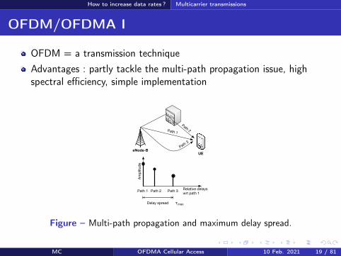
How to increase data rates Multicarrier transmissions
OFDMOFDMA II
If τmax gt Tsymb rArr Inter-Symbol Interference (ISI)1τmax asymp channel coherence bandwidth1Tsymb asymp signal bandwidthWider is the signal bandwidth higher is the ISIOFDM divides the global bandwidth in small frequency sub-channelsor sub-carriers with bandwidth ∆f 1τmax
ISI is almost completely removed
MC OFDMA Cellular Access 10 Feb 2021 20 81
How to increase data rates Multicarrier transmissions
OFDMOFDMA III
Frequencyf1 f2 f3 Frequencyf1 f2 f3
FDM OFDM
Figure ndash Comparison between OFDM and FDM in terms of spectral efficiency
Higher spectral efficiency than FDMPartial overlapping of the sub-channels thanks to the orthogonalitybetween sub-carriers
MC OFDMA Cellular Access 10 Feb 2021 21 81
How to increase data rates Multicarrier transmissions
OFDMOFDMA IV
times
times
times
times
times
times
TSymb
f1
f2
f3f1 f2 f3
FFT
IFFT
Time domain Frequency domain
Δf=f2-f1=1TSymb
QAM
QAM
QAM
Figure ndash OFDM signal in time and frequency domains
Orthogonality When the signal of sub-carrier n is maximum thesignal of all other sub-carriers is nullOrthogonality is obtained when ∆f = 1TSymb
Time domain The OFDM symbol is the sum of modulatedsub-carriers multiplied by a rectangle (gate) function
MC OFDMA Cellular Access 10 Feb 2021 22 81
How to increase data rates Multicarrier transmissions
OFDMOFDMA V
t
Copy
path 1
path 2
path 3
TSymb
τmax
Tg Tu
Figure ndash Guard intervalcyclic prefix of an OFDM symbol
To completely remove residual ISI one adds a cyclic prefix
MC OFDMA Cellular Access 10 Feb 2021 23 81
How to increase data rates Multicarrier transmissions
OFDMOFDMA VI
SPModulation
QAM IFFTAdd
cyclic
prefixPS
Remove
cyclic
prefixPS
De-
modulation
QAMFFT SP
frequencyDomain
time
System bandwidth ~ N sub-carriers
user bandwidth~ M sub-carriers
f f
1 2
3
4
= QAM symbol1 2
3
4
Transmit antenna
Receive antenna
SP SerialParallel PS ParallelSerial
Figure ndash OFDMOFDMA transmission and reception chains
The OFDM signal is easy to modulate and demodulate
MC OFDMA Cellular Access 10 Feb 2021 24 81
How to increase data rates Multicarrier transmissions
OFDMOFDMA VIIOFDM has two drawbacks (1) Inter-carrier interference (due toimperfect synchronization or strong Doppler effect) and (2) High Peakto Average Ratio (PAPR)
Pmax
Pmoy
Power amplifier input
Am
plifi
er
outp
ut
PmaxPmoy
Saturation
Backoff
Figure ndash Peak to Average Ratio of the OFDM signal
MC OFDMA Cellular Access 10 Feb 2021 25 81
How to increase data rates Multicarrier transmissions
OFDMOFDMA VIII
OFDM = transmission technique
OFDMA = multiple access method based on OFDM
Groups of sub-carriers can be allocated to different users
rArr no intra-cell interference (6= CDMA)
Radio resource allocation in the timefrequency domain
MC OFDMA Cellular Access 10 Feb 2021 26 81
How to increase data rates Multicarrier transmissions
SC-FDMA I
High PAPR rArr an issue for the ULSC-FDMA = Transmission technique with low PAPR for the UL
SPModulation
QAM
IFFTNgtM
points
Add
cyclic
prefixPS
Remove
cyclic
prefixPS
De-
modulation
QAM
FFTNgtM
pointsSP
FFTM
points
0
0000
System bandwidth ~ N sub-carriers
user bandwidth~ M sub-carriers
f
IFFTM
points
0
0000
time frequencyDomain
time
f
1
2
3
4
1
2
3
4
1
2
3
4
1
2
3
4
3 = QAM symbols of a user1 2 4
Transmit antenna
Receive antenna
SP SerialParallel PS ParallelSerial
Figure ndash SC-FDMA transmission and reception chains
MC OFDMA Cellular Access 10 Feb 2021 27 81
How to increase data rates Multicarrier transmissions
SC-FDMA II
The FFT spreads every QAM symbol over M sub-carriers
Every sub-carrier successively carriers all QAM symbols
At a given instant a unique QAM symbol is transmitted
The resulting PAPR is thus the same as for a QAM modulation
The remaining N minusM sub-carriers are available and can be allocatedto other users
MC OFDMA Cellular Access 10 Feb 2021 28 81
How to increase data rates Multicarrier transmissions
LTE configurations I
Configuration ∆f (kHz) Cyclic prefix (micros) Tu (micros)Normal prefix 15 52 (first symbol) 666
47 (other symbols)Extended prefix 15 167 666
Table ndash OFDM parameters on the downlink of LTE
Normal configuration 7 OFDM symbols per slot small prefixduration rArr relatively small cells (cell radius lt 2 Km)Extended configuration higher prefix duration 6 OFDM symbols perslot rArr larger cells (up to 10 Km) and single frequency networks (forbroadcast multicast services)
MC OFDMA Cellular Access 10 Feb 2021 29 81
How to increase data rates Multicarrier transmissions
LTE configurations II
Transmission techniques Keep this in mind OFDM advantages combat and take advantage of multi-pathpropagation high spectral efficiency easy and cheap implementationOFDM drawbacks Inter-carrier interference (ICI) PAPROFDMASC-FDMA are multiple access schemesSC-FDMA advantage A solution for a low PAPR ULSC-FDMA drawback A user can be allocated only a set of contiguoussub-carriersSpectral separation between sub-carriers is constant equal to 15 KHzwhatever the total signal bandwidth
MC OFDMA Cellular Access 10 Feb 2021 30 81
How to increase data rates Multiple antenna techniques
MIMO gains
Diversity gain several independent copies of the signal are availableat the receiver improve the robustness of the signalArray gain transmission side energy is focused in one or severaldirections (beamforming) reception side more energy is captured byseveral antennas improve the SNR may reduce interferencesMultiplexing gain several parallel flows are simultaneouslytransmitted the SISO channel capacity is multiplied by min(MN)where M and N are the number of transmit and receive antennas respTypical configurations 2times 2 and 4times 2 then 4times 4
MC OFDMA Cellular Access 10 Feb 2021 31 81
How to increase data rates Multiple antenna techniques
Transmit diversity (TM2)
SFBCCoding
s2 s1s2
s1
s1
-s2
Figure ndash Transmit diversity
2 or 4 transmit antennasSpace-Time Block Code (SFBC) Alamouti code [4] in the frequencydomainImproves the robustness of the signal without increasing the data rateOpen loopBackup transmission mode for other modes
MC OFDMA Cellular Access 10 Feb 2021 32 81
How to increase data rates Multiple antenna techniques
Spatial multiplexing (TM3 open loop TM4 closed loop)
Pre-coding
flow 1
flow 2
(a) Open loop
Pre-coding
flow 1
flow 2
(b) Closed loop
Figure ndash Spatial multiplexing
Several flows are simultaneously transmitted (2 or 4 antennas)Open loop precoding matrices are known at the receiver and changein a cyclic manner at the transmitterClosed loop the UE feedbacks its preferred precoding matrix thissolution is well adapted to UEs in low mobility
MC OFDMA Cellular Access 10 Feb 2021 33 81
How to increase data rates Multiple antenna techniques
TM5 Multi-user MIMO
eNode-B
(a) DL
eNode-B
(b) UL
eNBtransmitpower
UE2
UE1
UE1
UE2
UE1
UE2
Figure ndash MU-MIMO transmission (a) on the downlink and (b) on the uplink
Two simultaneous flows on a single timefrequency resourceTechnique similar to the spatial multiplexing scheme with closed loop
MC OFDMA Cellular Access 10 Feb 2021 34 81
How to increase data rates Multiple antenna techniques
TM6 and TM7 Beamforming
Node-B
UE
Figure ndash Beamforming
An antenna array is used to create an antenna beam in the directionof the UE rArr increase useful signal power at the receiverPilot signals specific to the UE are required
MC OFDMA Cellular Access 10 Feb 2021 35 81
How to increase data rates Multiple antenna techniques
Remember
MIMO Keep this in mind Transmit diversity improves the signal robustnessSpatial multiplexing increases data rates in good radio conditionsBeamforming increases the useful signal powerOpen loop no feedback from UEs (for fast UEs)Closed loop feedback from UEs (more efficient but for slow UEs)
MC OFDMA Cellular Access 10 Feb 2021 36 81
Radio resource organization Frame Structure
Frame structure (type 1 for FDD)
0 1 2 3 18 19
One radio frame Tf = 307 200 T
s = 10 ms
One sub-frame 30 720 Ts = 1 ms
One slot Tslot
= 15 360 Ts = 05 ms
0 1 2 3 4 5 6
160 2048 144 2048 144 2048 144 2048 144 2048 144 2048 144 2048
One OFDMSC-FDMA symbol = 666 micros
512 2048
0 1 2 3 4 5
Short prefix
Extended(15 kHz)
Figure ndash Frame structure type 1 in LTE FDD for 20 MHz (from [1])
MC OFDMA Cellular Access 10 Feb 2021 37 81
Radio resource organization Reference Signals
Reference signals I
DC (Direct Current)∆f = 15 kHz
2048 sub-carriers
1200 used sub-carrierGuard band Guard band
Pilot sub-carriers(signaux de reacutefeacuterence)
Data sub-carriers
Central frequency
Figure ndash Data pilot (reference signals) and null (carrier frequency and guardbands) sub-carriers on the DL of LTE
Reference signals are required for the channel estimation and thedecoding of user data
MC OFDMA Cellular Access 10 Feb 2021 38 81
Radio resource organization Reference Signals
Reference signals II
Port 0 Port 1 Port 2 Port 3t
f One antenna port
Two antenna ports
Four antenna ports
RE used by this antenna port to transmit a RS
RE free of transmission on this port
RE
0 1 2 3 4 5 6 0 1 2 3 4 5 6
RB
Figure ndash Reference signals (from [1])MC OFDMA Cellular Access 10 Feb 2021 39 81
Radio resource organization Resource elements and blocks
Resource elements (RE) and blocks (RB) I
f
t
Slot (05 ms)
Sub-frame (1 ms)
180 kHz
UE1
UE2
UE3
UE412 s
ub
-carr
iers
of
15 K
Hz
7 OFDMSC-FDMA symbols
RE
RB
Figure ndash Resource Elements and Resource Blocks in LTE in normal configuration
MC OFDMA Cellular Access 10 Feb 2021 40 81
Radio resource organization Resource elements and blocks
Resource elements (RE) and blocks (RB) II
1 RE = 1 sub-carrier times 1 OFDMSC-FDMA symbol
1 RB = 12 sub-carriers times 7 OFDMSC-FDMA symbols
Minimum amount of resource allocated to a UE 2 successive RBs
Parameter Bandwidth (MHz)14 3 5 10 15 20
FFT size 128 256 512 1024 1536 2048Used sub-carriers 72 180 300 600 900 1200
RB 6 15 25 50 75 100
Table ndash Available radio resources vs signal bandwidth (from [3])
MC OFDMA Cellular Access 10 Feb 2021 41 81
Radio resource organization Resource elements and blocks
Remember
Radio resource organization Keep this in mind Radio resources are organized in the time-frequency domain (orslot-sub-carrier)1 radio frame (10 ms) = 10 sub-frames (1 ms) = 20 slots (0 5 ms)1 RE = 1 sub-carriers times 1 symbol1 RB = 12 sub-carriers times 7 symbolsMinimum allocation 2 successive RBs (every 1 ms)20 MHz 100 RB
MC OFDMA Cellular Access 10 Feb 2021 42 81
Radio resource organization Downlink channels
Downlink physical channels
1 2 3 4 6 7 8 9
Radio frame (10 ms)
PBCH
PSSSSS
Sub-frame (1 ms)
SSS PSS
DC
10
8 M
Hz
Slot 0 Slot 1
0 5 6 0 1 2 3 6 0 6 6
PDSCH
PDSCH
1 2 1 2 0
PDCCH1 2 or 3 OFDM symbols
signaled by the PCFICH
PCFICH
A PHICHgroup
Syste
m b
and
wid
th
Figure ndash Mapping of downlink physical channels on the radio frameMC OFDMA Cellular Access 10 Feb 2021 43 81
Radio resource organization Uplink channels
Uplink physical channels I
Time location defined by the PRACH config
f
t
Syste
m b
an
dw
idth
Frame (10 ms)
6R
B6R
B
Frequency locationdefined byhigher layers
PRACH period
1 or 2 frames depending on the PRACH configuration
PUCCH
PUCCH
PUSCH
Figure ndash Position of the PRACH PUSCH and PUCCH in the LTE frame
MC OFDMA Cellular Access 10 Feb 2021 44 81
Radio resource organization Uplink channels
Uplink physical channels II
f
tSlot (05 ms)
0 1 2 3 4 5 6
PUSCH
UE1
UE2
UE3
DM
RS
DM
RS
DM
RS
Figure ndash DMRS during a PUSCH transmission (from [1])
MC OFDMA Cellular Access 10 Feb 2021 45 81
Radio resource organization Uplink channels
Transport and logical channels
Transport channels
Control informations
Physical channels
Uplink Downlink
RACH UL-SCH
UCI
PRACH PUSCH PUCCH
DL-SCH
DCI
PDSCH PDCCH
CFI
PCFICH
HI
PHICH
PCH BCH
PBCH
MCH
PMCH
CCCH
Logical channels
DTCH
DCCH
PCCH DTCH
DCCH
BCCH MCCH MTCHCCCH
Figure ndash Mapping of physical transport and logical channels
MC OFDMA Cellular Access 10 Feb 2021 46 81
How to synchronize
Section 5
How to synchronize
MC OFDMA Cellular Access 10 Feb 2021 47 81
How to synchronize Objectifs
Objectives
Objectives time and frequency PCI (Physical Cell Identifier) andSystem Informations acquisitionPCI 504 identities classified in 168 groups of 3System Informations network identity common channelsconfiguration selectionreselectionhandover parameters informationson neighbor cells They are organized in one MIB (Master InformationBlock) and several SIBs (System Information Block)
MC OFDMA Cellular Access 10 Feb 2021 48 81
How to synchronize Cell search
Cell search I
1 Find the most powerful carrier in the operator spectrum2 PSS decoding (62 sub-carrier in the middle of the band whatever the
bandwidth) rArr the PSS broadcasts a sequence among 33 SSS decoding rArr the SSS broadcasts 2 pseudo-random sequences of
62 bits on slots 0 and 10 there are 168 possible pairs4 Radio quality evaluation using RSs rArr the UE is synchronized if the
quality is sufficient the transmitted sequence and the position of theRSs in the frame depend on the PCI so that RSs from neighboringcells do not interfere
MC OFDMA Cellular Access 10 Feb 2021 49 81
How to synchronize Cell search
Cell search II
5 PBCH decoding rArr MIB (Master Information Block) antennaconfiguration the position of the PBCH does not depend on thebandwidth it is scrambled by a sequence that depends on the PCIThe MIB includes
the bandwidth (in of RBs)PHICH parametersthe frame number
6 PCFICH decoding rArr Number of OFDM symbols dedicated toPDCCHs
7 PDCCH decoding rArr DCI message (with SI-RNTI address) givingthe location of the SIB1 in the PDSCH
8 SIB1 decoding rArr scheduling of other SIBs
9 SIBs (System Information Block) are received on the PDSCH
MC OFDMA Cellular Access 10 Feb 2021 50 81
How to access the network
Section 6
How to access the network
MC OFDMA Cellular Access 10 Feb 2021 51 81
How to access the network Objectives
Objectives
Objectives Establishment or re-establishment of the RRC connectionIntra-system handoversUpon arrival of DL or UL data whereas the UE has lost itssynchronization with the network
2 random access types contention-based conflict-freeContention-based access can be used in all casesConflict-free access for handovers or upon arrival of DL data
PRACH transmission on the uplink then transmission of a CCCHmessage signaling the reason of the access
MC OFDMA Cellular Access 10 Feb 2021 52 81
How to access the network Random access
Contention-based access I
System Information (DL-SCH)(PRACH config PRACH location preamble format sequence list)
Random Access Preamble (RACH)(size of the L2L3 message)
Random Access Response (DL-SCH)(RA-RNTITA temp C-RNTI UL allocation)
CCCH message (UL-SCH)
Collision resolution (DL-SCH)(SDU CCCH)
UEeNB
Figure ndash Contention-based access in LTE
MC OFDMA Cellular Access 10 Feb 2021 53 81
How to access the network Random access
Contention-based access II1) The UE obtains from SIB the PRACH configuration the PRACH
frequency location the preamble format the target received powerand the list of sequences to be used (64 Zadoff-Chu sequencesincluding those reserved to the conflict-free access)
3) The UE chooses at random one sequence among those available4) It sends the preamble on the PRACH with an open loop power
control the UE tries to compensate the path-loss by usingmeasurements made on DL RSs rArr power control makes sequencedetection easier at the BS
Collision several UEs have used the same sequence on the same radioresourceCapture the eNB manages to decode one of the messages in collision
MC OFDMA Cellular Access 10 Feb 2021 54 81
How to access the network Random access
Contention-based access III
5) If there is no answer from the network power ramping (like inCDMA) ie the UE stepwise increases its transmit power
6) The RAR identifies the decoded preamble + provides the timingadvance (TA) + gives an UL allocation + a temporary identity(temporary C-RNTI address)
7) CCCH message on the PUSCH = eg a RRC connection request +temporary C-RNTI
8) Collision resolution the eNB sends a copy of the CCCH message onthe DL The UE that recognizes its message adopts the temporaryC-RNTI (now its address) other UEs leave the procedure
MC OFDMA Cellular Access 10 Feb 2021 55 81
How to access the network Random access
Conflict-free access
The UE has a valid identity (C-RNTI)The eNB sends a (DCI) message on the PDCCH including theZadoff-Chu sequence to be usedCollisions are no more possible no collision resolution phase
MC OFDMA Cellular Access 10 Feb 2021 56 81
How to send and receive data
Section 7
How to send and receive data
MC OFDMA Cellular Access 10 Feb 2021 57 81
How to send and receive data Objectives
Objectives
Objectives Resource allocation tell UEs on which radio resources they will receivedata on the DL-SCH or on which resource they are allowed to transmiton the UL-SCHUE scheduling allocate RBs to UEs as a function of their demand andtheir radio conditionsError control ARQ and HARQ retransmissionsMeasurement feedbacks the UE tells the network the downlinkchannel radio quality or its preferred MIMO precoding matrix
MC OFDMA Cellular Access 10 Feb 2021 58 81
How to send and receive data Resource allocation
Resource allocation I
Location of resources in the sub-frame modulation and coding schemeare signaled in Downlink Control Information (DCI) messagestransmitted on the PDCCHs
Format Description0 Resource allocation on the PUSCH1 PDSCH resource allocation in TM1 TM2 TM71A PDSCH compact allocation and PRACH signature1B PDSCH resource allocation in TM61C PDSCH very compact allocation1D PDSCH compact allocation in TM52 PDSCH compact allocation in TM42A PDSCH compact allocation in TM33 Power control on PUCCHPUSCH (2 bits)3A Power control on PUCCHPUSCH (1 bit)
Table ndash DCI formats
MC OFDMA Cellular Access 10 Feb 2021 59 81
How to send and receive data Resource allocation
Resource allocation II
DCI 0 example A flag to differentiate 1 and 1AA flag for frequency hopping on the PUSCHResource block allocationModulation and coding scheme redundancy version for HARQHARQ new transmission indicatorA power control command for the ULCyclic shift to be applied to ZC sequence for DMRSA CQI request
Every DCI includes a CRC scrambled with a RNTI identityC-RNTI = to address a unique UEP-RNTI = paging messageSI-RNTI = SIBRA-RNTI = random access response
MC OFDMA Cellular Access 10 Feb 2021 60 81
How to send and receive data Scheduling
Scheduling I
Fast (every 1 ms) and adaptive (modulation and coding are adaptedto radio conditions) schedulingDL scheduling decisions are based on CQI feedbacks buffer statusand priorities between logical channelsUL the UE has to feedback its buffer status and radio resource needsby using either the PUCCH (scheduling request) or the UL-SCH (MACcontrol messages)
MC OFDMA Cellular Access 10 Feb 2021 61 81
How to send and receive data Scheduling
Scheduling IIAlgorithm LTE offers a new degree of freedom wrt HSPA thepossibility to schedule users on different radio blocks
Channel q
ualit
y
fPRB1 PRB2 PRB3 PRB4 PRB5
Channel UE1
Channel UE2
Channel UE3
Scheduling decisions UE2 UE3 UE1 UE3 UE2
Figure ndash Frequency Dependent Packet Scheduling (FDPS) in LTE
MC OFDMA Cellular Access 10 Feb 2021 62 81
How to send and receive data Scheduling
Scheduling III
f
t
Syste
m b
an
dw
idth
Sub-frame (1 ms)
f
t
Comb onesub-carrieris used outof two
(a) SRS transmission without frequency hopping
(b) SRS transmission with frequency hopping
Figure ndash Sounding Reference Signals (SRS) transmissions
The eNB estimates the channel quality on the UL thanks to SRS
SRS is transmitted on a bandwidth much larger than the one allocated to UEtransmissions
SRS from different UEs are multiplexed in time (different sub-frames and periods)frequency (different sets of RBs oddeven sub-carriers) or code (differentsequences)
MC OFDMA Cellular Access 10 Feb 2021 63 81
How to send and receive data Error control
ARQ and HARQ
Like in HSPA HARQ is in the MAC layer and ARQ in the RLCHARQ DL sequence number is signaled in the PDCCH ACKNACKare fed back in the PUSCH (with data) or in the PUCCHHARQ UL ACKNACK transmitted in the PHICHARQ Transparent Mode (TM) (no header no segmentation orconcatenation) Unacknowledged (UM) (header with sequencenumber) Acknowledged (AM) (ARQ)
MC OFDMA Cellular Access 10 Feb 2021 64 81
How to send and receive data Measurements
Measurements
Radio quality measurements CQI (Channel Quality Indicator) modulation (QPSK 16-QAM or64-QAM) and transport block maximum size that a UE can receivewith a BLERlt10 (Block Error Rate)RI (Rank Indicator) rank of the DL transmission = number ofindependent spatial layers that can be usedPMI (Precoding Matrix Indicator) UE preferred precoding matrix Wfor transmission modes with closed loop
Physical channels PUSCH for aperiodic feedbacks with data transmissionPUCCH for periodic feedbacks
MC OFDMA Cellular Access 10 Feb 2021 65 81
Terminals categories
Section 8
Terminals categories
MC OFDMA Cellular Access 10 Feb 2021 66 81
Terminals categories
Terminals categories
Caracteristics Cat 1 Cat 2 Cat 3 Cat 4 Cat 5Max number ofbits per TTI (DL) 10296 51024 102048 150752 299552
Max number ofbits per TTI (UL) 5160 25456 51024 51024 75376
Max data rate(DL) 10 Mbps 50 Mbps 100 Mbps 150 Mbps 300 Mbps
Max data rate(UL) 5 Mbps 25 Mbps 50 Mbps 50 Mbps 75 Mbps
64 QAM (UL) No No No No YesMIMO (DL) Option 2times 2 2times 2 2times 2 4times 4
Table ndash Terminal categories in LTE
For example the Semsong S5 is cat 4 the Semsong S6 is cat 6 (Release 1030050 Mbps) the Semsong S8 is cat1613 (Release 12 1050150 Mbps MIMO4x4 256-QAM 5CA) Semsong S10 is cat 2013 (2000 Mbps up to 8 MIMOlayers 256-QAM 7CA)
MC OFDMA Cellular Access 10 Feb 2021 67 81
Summary on channels
Section 9
Summary on channels
MC OFDMA Cellular Access 10 Feb 2021 68 81
Summary on channels
Physical channels DL I
PDSCH (Physical Downlink Shared Ch) physical shared channel for data
RS (Reference Signals) pilots required to estimate radio quality and toallow decoding on the DL
SS (Synchronization Signals) = PSS (Primary)+SSS (Secondary) for timeand frequency synchronization
PBCH (Physical Broadcast Ch) beacon MIB transmission
PCFICH (Physical Control Format Indicator Ch) tell the UEs how manyOFDM symbols are dedicated to the control part of the sub-frame (CFI)
PDCCH (Physical Downlink Control Ch) control informations (DCI resource allocation UE identity HARQ information MIMO etc)
PHICH (Physical Hybrid ARQ Indicator Ch) ACKNACK responses toHARQ transmissions from a UE (HI)
MC OFDMA Cellular Access 10 Feb 2021 69 81
Summary on channels
Physical channels UL I
In UL a UE is not able to multiplex different physical channels in the frequencydomain because of SC-FDMA limitation rArr time multiplexing is required
DMRS (Demodulation Reference Signal) used by the eNB to estimate thechannel and make radio quality measurements on the signal transmitted by theUE DMRS are sent in conjunction with PUCCH and PUSCH
SRS (Sounding Reference Signal) pilots used by the scheduler for the radioquality estimation on a bandwidth larger than the one allocated to the UE
PUCCH (Physical Uplink Control Ch) control informations UCI includingchannel quality (CQI) MIMO (closed loop) or HARQ (ACKNACK) informations
PUSCH (Physical Uplink Shared Ch) shared physical channels for data andcontrol
If a UE has data to transmit it uses the PUSCH for data and control Otherwiseit uses the PUCCH for the control
MC OFDMA Cellular Access 10 Feb 2021 70 81
Summary on channels
Transport channels DL
DL-SCH (DL Shared Ch) shared channel for data associated toPDSCHPCH (Paging Ch) broadcast of paging messages on the PDSCHBCH (Broadcast Ch) broadcast of system informations (SIBs) onthe PBCH and on the PDSCHDCI (DL Control Indicator) control information transmitted on thePDCCHs (transport format resource allocation HARQ and MIMOinformations power control commands)CFI (Control Format Indicator) number of OFDM symbols (12 or 3)used by PDCCHs at the beginning of every sub-frame CFI is sent onthe PCFICHHI (HARQ Indicator) ACK or NACK in response to a transmissionon the UL-SCH HI is transmitted on the PHICH
MC OFDMA Cellular Access 10 Feb 2021 71 81
Summary on channels
transport channels UL
RACH (Random Access Ch) random accessUL-SCH (UL Share Ch) shared channel for data and controlassociated to PUSCH User data and control informations aremultiplexed in time and frequency on the PUSCHUCI (UL Control Indicator) control information transmitted by thePUCCH (channel quality CQI closed loop MIMO informationsPMIRI ACKNACK of HARQ scheduling request)
MC OFDMA Cellular Access 10 Feb 2021 72 81
Summary on channels
Logical channels
Logical channel Type Description LinkBCCH Control System information DLPCCH Control Paging DLCCCH Control Control without RRC conn ULDLDCCH Controcircle Dedicated control ULDLDTCH Traffic user plane ULDL
Table ndash Logical channels in LTE DL and UL
BCCH (Broadcast COntrol Ch) system information associated to BCH for theMIB and DL-SCH for the SIBs
PCCH (Paging Control Ch) paging associated to PCH
CCCH (Common Control Ch) control messages between the network and UEswithout RRC connection associated to DL-SCH and UL-SCH
DCCH (Dedicated Control Ch) control messages between the network and UEswith RRC connection associated to DL-SCH and UL-SCH
MC OFDMA Cellular Access 10 Feb 2021 73 81
Conclusion
Section 10
Conclusion
MC OFDMA Cellular Access 10 Feb 2021 74 81
Conclusion
Conclusion
LTE A brand new standardA certain simplicity that is reminiscent of GSMSimilarities with 3G (channels HARQ MAC RLC etc)New features (MIMO MU-MIMO multi-carrier transmissions)
After LTE LTE-A R13 frozen in Mar 2016 (LTE Pro) R14 on goingR15 is called 5G New Radio (NR) and is the first 5G releasePeak rates of the order of 1GbpsCarrier aggregation discontinuous resource allocation on the ULMIMO 8times8 relays HetNets CoMP Self-Organized NetworksMBMS NB-IoT etc
MC OFDMA Cellular Access 10 Feb 2021 75 81
Conclusion
References I
3GPPTechnical Specification 36211 Physical channels and modulationDec 2009
3GPPTechnical Specification 36300 Evolved Universal Terrestrial RadioAccess (E-UTRA) and Evolved Universal Terrestrial Radio AccessNetwork (E-UTRAN) Overall description Apr 2010
3GPPTechnical Specification 36104 Base Station (BS) radio transmissionand reception Jun 2011
MC OFDMA Cellular Access 10 Feb 2021 76 81
Conclusion
References II
S M AlamoutiA simple transmit diversity technique for wireless communicationsIEEE J on Selected Areas in Communications 16(8) 1451ndash1458 Oct1998
MC OFDMA Cellular Access 10 Feb 2021 77 81
Conclusion
Acronyms I
AM ARQ Acknowledged ModeARQ Automatic Repeat on RequestBCCH Broadcast Control ChannelBCH Broadcast ChannelBLER Block Error RateBPSK Binary Phase Shift KeyingBS Base Station
CCCH Common Control ChannelCDMA Code Division Multiple AccessCFI Control Format Indocator
CoMP Coordinated Multi-PointCQI Channel Quality IndicatorCRC Cyclic Redundancy CodeD2D Device to DeviceDCCH Dedicated Control ChannelDCI Downlink Control InformationDL Downlink
DL-SCH Downlink Shared ChannelDMRS Demodulation Reference SignalDTCH Dedicated Traffic ChanneleNB eNode-BEPC Evolved Packet Core
E-UTRAN Evolved UTRANFDD Frequency Division DuplexFDPS Frequency Dependent Packet SchedulingFFT Fast Fourier TransformGSM Groupe Speacutecial MobileHARQ Hybrid Automatic Repeat on Request
MC OFDMA Cellular Access 10 Feb 2021 78 81
Conclusion
Acronyms IIHI HARQ Indicator
HSPA High Speed Packet AccessHSDPA High Speed Downlink Packet AccessHSPA High Speed Uplink Packet AccessICI Inter-Carrier InterferenceIFFT Inverse Fast Fourier TransformIMT International Mobile TelecommunicationsISI Inter-Symbol InterferenceLTE Long Term EvolutionMAC Medium Access ControlMBMS Multimedia Broadcast Multicast ServiceMIB Master Information BlockMIMO Multiple Input Multiple OutputMME Mobility Management Entity
MU-MIMO Multi-User MIMONAS Non Access StratumOFDM Orthogonal Frequency Division MultiplexOFDMA Orthogonal Frequency Division Multiple AccessPAPR Peak to Average Power RatioPBCH Physical Broadcast ChannelPCFICH Physical Control Format Indicator ChannelPCCH Paging Control ChannelPCH Paging ChannelPCI Physical Cell Identifier
PDCCH Physical Downlink Control ChannelPDCP Packet Data Convergence ProtocolPDSCH Physical Downlink Shared ChannelPDU Protocol Data Unit
MC OFDMA Cellular Access 10 Feb 2021 79 81
Conclusion
Acronyms IIIPHICH Physical Hybrid ARQ Indicator ChannelPMI Precoding Matrix IndicatorPSS Primary Synchronization Signal
PUCCH Physical Uplink Control ChannelPUSCH Physical Uplink Shared ChannelQAM Qadrature Amplitude ModulationQPSK Quadrature Phase Shift KeyingRACH Random Access ChannelRAR Random Access ResponseRB Resource BlockRE Resource ElementRI Rank IndicatorRLC Radio Link ControlRNC Radio Network ControllerRNTI Radio Network Temporary IdentifierROHC Robust Header CompressionRRC Radio Resource ControlRS Reference Signal
SC-FDMA Single Carrier Frequency Division Multiple AccessSDU Service Data UnitSFBC Space-Time Block CodeSGW Serving GatewaySIB System Information BlockSISO Single Input Single OutputSNR Signal to Noise RatioSRS Sounding Reference SignalSSS Secondary Synchronization SignalTA Timing Advance
MC OFDMA Cellular Access 10 Feb 2021 80 81
Conclusion
Acronyms IV
TDD Time Division DuplexTM Transmission ModeTM ARQ Transparent ModeTTI Transmission Time IntervalUCI Uplink Control InformationUE User EquipmentUM ARQ Unacknowledged Mode
UMTS Universal Mobile Telecommunications SystemUL Uplink
UL-SCH Uplink Shared ChannelUTRAN UMTS Terrestrial Radio Access NetworkWCDMA Wideband Code Division Multiple Access
MC OFDMA Cellular Access 10 Feb 2021 81 81
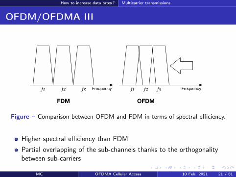
How to increase data rates Multicarrier transmissions
LTE configurations II
Transmission techniques Keep this in mind OFDM advantages combat and take advantage of multi-pathpropagation high spectral efficiency easy and cheap implementationOFDM drawbacks Inter-carrier interference (ICI) PAPROFDMASC-FDMA are multiple access schemesSC-FDMA advantage A solution for a low PAPR ULSC-FDMA drawback A user can be allocated only a set of contiguoussub-carriersSpectral separation between sub-carriers is constant equal to 15 KHzwhatever the total signal bandwidth
MC OFDMA Cellular Access 10 Feb 2021 30 81
How to increase data rates Multiple antenna techniques
MIMO gains
Diversity gain several independent copies of the signal are availableat the receiver improve the robustness of the signalArray gain transmission side energy is focused in one or severaldirections (beamforming) reception side more energy is captured byseveral antennas improve the SNR may reduce interferencesMultiplexing gain several parallel flows are simultaneouslytransmitted the SISO channel capacity is multiplied by min(MN)where M and N are the number of transmit and receive antennas respTypical configurations 2times 2 and 4times 2 then 4times 4
MC OFDMA Cellular Access 10 Feb 2021 31 81
How to increase data rates Multiple antenna techniques
Transmit diversity (TM2)
SFBCCoding
s2 s1s2
s1
s1
-s2
Figure ndash Transmit diversity
2 or 4 transmit antennasSpace-Time Block Code (SFBC) Alamouti code [4] in the frequencydomainImproves the robustness of the signal without increasing the data rateOpen loopBackup transmission mode for other modes
MC OFDMA Cellular Access 10 Feb 2021 32 81
How to increase data rates Multiple antenna techniques
Spatial multiplexing (TM3 open loop TM4 closed loop)
Pre-coding
flow 1
flow 2
(a) Open loop
Pre-coding
flow 1
flow 2
(b) Closed loop
Figure ndash Spatial multiplexing
Several flows are simultaneously transmitted (2 or 4 antennas)Open loop precoding matrices are known at the receiver and changein a cyclic manner at the transmitterClosed loop the UE feedbacks its preferred precoding matrix thissolution is well adapted to UEs in low mobility
MC OFDMA Cellular Access 10 Feb 2021 33 81
How to increase data rates Multiple antenna techniques
TM5 Multi-user MIMO
eNode-B
(a) DL
eNode-B
(b) UL
eNBtransmitpower
UE2
UE1
UE1
UE2
UE1
UE2
Figure ndash MU-MIMO transmission (a) on the downlink and (b) on the uplink
Two simultaneous flows on a single timefrequency resourceTechnique similar to the spatial multiplexing scheme with closed loop
MC OFDMA Cellular Access 10 Feb 2021 34 81
How to increase data rates Multiple antenna techniques
TM6 and TM7 Beamforming
Node-B
UE
Figure ndash Beamforming
An antenna array is used to create an antenna beam in the directionof the UE rArr increase useful signal power at the receiverPilot signals specific to the UE are required
MC OFDMA Cellular Access 10 Feb 2021 35 81
How to increase data rates Multiple antenna techniques
Remember
MIMO Keep this in mind Transmit diversity improves the signal robustnessSpatial multiplexing increases data rates in good radio conditionsBeamforming increases the useful signal powerOpen loop no feedback from UEs (for fast UEs)Closed loop feedback from UEs (more efficient but for slow UEs)
MC OFDMA Cellular Access 10 Feb 2021 36 81
Radio resource organization Frame Structure
Frame structure (type 1 for FDD)
0 1 2 3 18 19
One radio frame Tf = 307 200 T
s = 10 ms
One sub-frame 30 720 Ts = 1 ms
One slot Tslot
= 15 360 Ts = 05 ms
0 1 2 3 4 5 6
160 2048 144 2048 144 2048 144 2048 144 2048 144 2048 144 2048
One OFDMSC-FDMA symbol = 666 micros
512 2048
0 1 2 3 4 5
Short prefix
Extended(15 kHz)
Figure ndash Frame structure type 1 in LTE FDD for 20 MHz (from [1])
MC OFDMA Cellular Access 10 Feb 2021 37 81
Radio resource organization Reference Signals
Reference signals I
DC (Direct Current)∆f = 15 kHz
2048 sub-carriers
1200 used sub-carrierGuard band Guard band
Pilot sub-carriers(signaux de reacutefeacuterence)
Data sub-carriers
Central frequency
Figure ndash Data pilot (reference signals) and null (carrier frequency and guardbands) sub-carriers on the DL of LTE
Reference signals are required for the channel estimation and thedecoding of user data
MC OFDMA Cellular Access 10 Feb 2021 38 81
Radio resource organization Reference Signals
Reference signals II
Port 0 Port 1 Port 2 Port 3t
f One antenna port
Two antenna ports
Four antenna ports
RE used by this antenna port to transmit a RS
RE free of transmission on this port
RE
0 1 2 3 4 5 6 0 1 2 3 4 5 6
RB
Figure ndash Reference signals (from [1])MC OFDMA Cellular Access 10 Feb 2021 39 81
Radio resource organization Resource elements and blocks
Resource elements (RE) and blocks (RB) I
f
t
Slot (05 ms)
Sub-frame (1 ms)
180 kHz
UE1
UE2
UE3
UE412 s
ub
-carr
iers
of
15 K
Hz
7 OFDMSC-FDMA symbols
RE
RB
Figure ndash Resource Elements and Resource Blocks in LTE in normal configuration
MC OFDMA Cellular Access 10 Feb 2021 40 81
Radio resource organization Resource elements and blocks
Resource elements (RE) and blocks (RB) II
1 RE = 1 sub-carrier times 1 OFDMSC-FDMA symbol
1 RB = 12 sub-carriers times 7 OFDMSC-FDMA symbols
Minimum amount of resource allocated to a UE 2 successive RBs
Parameter Bandwidth (MHz)14 3 5 10 15 20
FFT size 128 256 512 1024 1536 2048Used sub-carriers 72 180 300 600 900 1200
RB 6 15 25 50 75 100
Table ndash Available radio resources vs signal bandwidth (from [3])
MC OFDMA Cellular Access 10 Feb 2021 41 81
Radio resource organization Resource elements and blocks
Remember
Radio resource organization Keep this in mind Radio resources are organized in the time-frequency domain (orslot-sub-carrier)1 radio frame (10 ms) = 10 sub-frames (1 ms) = 20 slots (0 5 ms)1 RE = 1 sub-carriers times 1 symbol1 RB = 12 sub-carriers times 7 symbolsMinimum allocation 2 successive RBs (every 1 ms)20 MHz 100 RB
MC OFDMA Cellular Access 10 Feb 2021 42 81
Radio resource organization Downlink channels
Downlink physical channels
1 2 3 4 6 7 8 9
Radio frame (10 ms)
PBCH
PSSSSS
Sub-frame (1 ms)
SSS PSS
DC
10
8 M
Hz
Slot 0 Slot 1
0 5 6 0 1 2 3 6 0 6 6
PDSCH
PDSCH
1 2 1 2 0
PDCCH1 2 or 3 OFDM symbols
signaled by the PCFICH
PCFICH
A PHICHgroup
Syste
m b
and
wid
th
Figure ndash Mapping of downlink physical channels on the radio frameMC OFDMA Cellular Access 10 Feb 2021 43 81
Radio resource organization Uplink channels
Uplink physical channels I
Time location defined by the PRACH config
f
t
Syste
m b
an
dw
idth
Frame (10 ms)
6R
B6R
B
Frequency locationdefined byhigher layers
PRACH period
1 or 2 frames depending on the PRACH configuration
PUCCH
PUCCH
PUSCH
Figure ndash Position of the PRACH PUSCH and PUCCH in the LTE frame
MC OFDMA Cellular Access 10 Feb 2021 44 81
Radio resource organization Uplink channels
Uplink physical channels II
f
tSlot (05 ms)
0 1 2 3 4 5 6
PUSCH
UE1
UE2
UE3
DM
RS
DM
RS
DM
RS
Figure ndash DMRS during a PUSCH transmission (from [1])
MC OFDMA Cellular Access 10 Feb 2021 45 81
Radio resource organization Uplink channels
Transport and logical channels
Transport channels
Control informations
Physical channels
Uplink Downlink
RACH UL-SCH
UCI
PRACH PUSCH PUCCH
DL-SCH
DCI
PDSCH PDCCH
CFI
PCFICH
HI
PHICH
PCH BCH
PBCH
MCH
PMCH
CCCH
Logical channels
DTCH
DCCH
PCCH DTCH
DCCH
BCCH MCCH MTCHCCCH
Figure ndash Mapping of physical transport and logical channels
MC OFDMA Cellular Access 10 Feb 2021 46 81
How to synchronize
Section 5
How to synchronize
MC OFDMA Cellular Access 10 Feb 2021 47 81
How to synchronize Objectifs
Objectives
Objectives time and frequency PCI (Physical Cell Identifier) andSystem Informations acquisitionPCI 504 identities classified in 168 groups of 3System Informations network identity common channelsconfiguration selectionreselectionhandover parameters informationson neighbor cells They are organized in one MIB (Master InformationBlock) and several SIBs (System Information Block)
MC OFDMA Cellular Access 10 Feb 2021 48 81
How to synchronize Cell search
Cell search I
1 Find the most powerful carrier in the operator spectrum2 PSS decoding (62 sub-carrier in the middle of the band whatever the
bandwidth) rArr the PSS broadcasts a sequence among 33 SSS decoding rArr the SSS broadcasts 2 pseudo-random sequences of
62 bits on slots 0 and 10 there are 168 possible pairs4 Radio quality evaluation using RSs rArr the UE is synchronized if the
quality is sufficient the transmitted sequence and the position of theRSs in the frame depend on the PCI so that RSs from neighboringcells do not interfere
MC OFDMA Cellular Access 10 Feb 2021 49 81
How to synchronize Cell search
Cell search II
5 PBCH decoding rArr MIB (Master Information Block) antennaconfiguration the position of the PBCH does not depend on thebandwidth it is scrambled by a sequence that depends on the PCIThe MIB includes
the bandwidth (in of RBs)PHICH parametersthe frame number
6 PCFICH decoding rArr Number of OFDM symbols dedicated toPDCCHs
7 PDCCH decoding rArr DCI message (with SI-RNTI address) givingthe location of the SIB1 in the PDSCH
8 SIB1 decoding rArr scheduling of other SIBs
9 SIBs (System Information Block) are received on the PDSCH
MC OFDMA Cellular Access 10 Feb 2021 50 81
How to access the network
Section 6
How to access the network
MC OFDMA Cellular Access 10 Feb 2021 51 81
How to access the network Objectives
Objectives
Objectives Establishment or re-establishment of the RRC connectionIntra-system handoversUpon arrival of DL or UL data whereas the UE has lost itssynchronization with the network
2 random access types contention-based conflict-freeContention-based access can be used in all casesConflict-free access for handovers or upon arrival of DL data
PRACH transmission on the uplink then transmission of a CCCHmessage signaling the reason of the access
MC OFDMA Cellular Access 10 Feb 2021 52 81
How to access the network Random access
Contention-based access I
System Information (DL-SCH)(PRACH config PRACH location preamble format sequence list)
Random Access Preamble (RACH)(size of the L2L3 message)
Random Access Response (DL-SCH)(RA-RNTITA temp C-RNTI UL allocation)
CCCH message (UL-SCH)
Collision resolution (DL-SCH)(SDU CCCH)
UEeNB
Figure ndash Contention-based access in LTE
MC OFDMA Cellular Access 10 Feb 2021 53 81
How to access the network Random access
Contention-based access II1) The UE obtains from SIB the PRACH configuration the PRACH
frequency location the preamble format the target received powerand the list of sequences to be used (64 Zadoff-Chu sequencesincluding those reserved to the conflict-free access)
3) The UE chooses at random one sequence among those available4) It sends the preamble on the PRACH with an open loop power
control the UE tries to compensate the path-loss by usingmeasurements made on DL RSs rArr power control makes sequencedetection easier at the BS
Collision several UEs have used the same sequence on the same radioresourceCapture the eNB manages to decode one of the messages in collision
MC OFDMA Cellular Access 10 Feb 2021 54 81
How to access the network Random access
Contention-based access III
5) If there is no answer from the network power ramping (like inCDMA) ie the UE stepwise increases its transmit power
6) The RAR identifies the decoded preamble + provides the timingadvance (TA) + gives an UL allocation + a temporary identity(temporary C-RNTI address)
7) CCCH message on the PUSCH = eg a RRC connection request +temporary C-RNTI
8) Collision resolution the eNB sends a copy of the CCCH message onthe DL The UE that recognizes its message adopts the temporaryC-RNTI (now its address) other UEs leave the procedure
MC OFDMA Cellular Access 10 Feb 2021 55 81
How to access the network Random access
Conflict-free access
The UE has a valid identity (C-RNTI)The eNB sends a (DCI) message on the PDCCH including theZadoff-Chu sequence to be usedCollisions are no more possible no collision resolution phase
MC OFDMA Cellular Access 10 Feb 2021 56 81
How to send and receive data
Section 7
How to send and receive data
MC OFDMA Cellular Access 10 Feb 2021 57 81
How to send and receive data Objectives
Objectives
Objectives Resource allocation tell UEs on which radio resources they will receivedata on the DL-SCH or on which resource they are allowed to transmiton the UL-SCHUE scheduling allocate RBs to UEs as a function of their demand andtheir radio conditionsError control ARQ and HARQ retransmissionsMeasurement feedbacks the UE tells the network the downlinkchannel radio quality or its preferred MIMO precoding matrix
MC OFDMA Cellular Access 10 Feb 2021 58 81
How to send and receive data Resource allocation
Resource allocation I
Location of resources in the sub-frame modulation and coding schemeare signaled in Downlink Control Information (DCI) messagestransmitted on the PDCCHs
Format Description0 Resource allocation on the PUSCH1 PDSCH resource allocation in TM1 TM2 TM71A PDSCH compact allocation and PRACH signature1B PDSCH resource allocation in TM61C PDSCH very compact allocation1D PDSCH compact allocation in TM52 PDSCH compact allocation in TM42A PDSCH compact allocation in TM33 Power control on PUCCHPUSCH (2 bits)3A Power control on PUCCHPUSCH (1 bit)
Table ndash DCI formats
MC OFDMA Cellular Access 10 Feb 2021 59 81
How to send and receive data Resource allocation
Resource allocation II
DCI 0 example A flag to differentiate 1 and 1AA flag for frequency hopping on the PUSCHResource block allocationModulation and coding scheme redundancy version for HARQHARQ new transmission indicatorA power control command for the ULCyclic shift to be applied to ZC sequence for DMRSA CQI request
Every DCI includes a CRC scrambled with a RNTI identityC-RNTI = to address a unique UEP-RNTI = paging messageSI-RNTI = SIBRA-RNTI = random access response
MC OFDMA Cellular Access 10 Feb 2021 60 81
How to send and receive data Scheduling
Scheduling I
Fast (every 1 ms) and adaptive (modulation and coding are adaptedto radio conditions) schedulingDL scheduling decisions are based on CQI feedbacks buffer statusand priorities between logical channelsUL the UE has to feedback its buffer status and radio resource needsby using either the PUCCH (scheduling request) or the UL-SCH (MACcontrol messages)
MC OFDMA Cellular Access 10 Feb 2021 61 81
How to send and receive data Scheduling
Scheduling IIAlgorithm LTE offers a new degree of freedom wrt HSPA thepossibility to schedule users on different radio blocks
Channel q
ualit
y
fPRB1 PRB2 PRB3 PRB4 PRB5
Channel UE1
Channel UE2
Channel UE3
Scheduling decisions UE2 UE3 UE1 UE3 UE2
Figure ndash Frequency Dependent Packet Scheduling (FDPS) in LTE
MC OFDMA Cellular Access 10 Feb 2021 62 81
How to send and receive data Scheduling
Scheduling III
f
t
Syste
m b
an
dw
idth
Sub-frame (1 ms)
f
t
Comb onesub-carrieris used outof two
(a) SRS transmission without frequency hopping
(b) SRS transmission with frequency hopping
Figure ndash Sounding Reference Signals (SRS) transmissions
The eNB estimates the channel quality on the UL thanks to SRS
SRS is transmitted on a bandwidth much larger than the one allocated to UEtransmissions
SRS from different UEs are multiplexed in time (different sub-frames and periods)frequency (different sets of RBs oddeven sub-carriers) or code (differentsequences)
MC OFDMA Cellular Access 10 Feb 2021 63 81
How to send and receive data Error control
ARQ and HARQ
Like in HSPA HARQ is in the MAC layer and ARQ in the RLCHARQ DL sequence number is signaled in the PDCCH ACKNACKare fed back in the PUSCH (with data) or in the PUCCHHARQ UL ACKNACK transmitted in the PHICHARQ Transparent Mode (TM) (no header no segmentation orconcatenation) Unacknowledged (UM) (header with sequencenumber) Acknowledged (AM) (ARQ)
MC OFDMA Cellular Access 10 Feb 2021 64 81
How to send and receive data Measurements
Measurements
Radio quality measurements CQI (Channel Quality Indicator) modulation (QPSK 16-QAM or64-QAM) and transport block maximum size that a UE can receivewith a BLERlt10 (Block Error Rate)RI (Rank Indicator) rank of the DL transmission = number ofindependent spatial layers that can be usedPMI (Precoding Matrix Indicator) UE preferred precoding matrix Wfor transmission modes with closed loop
Physical channels PUSCH for aperiodic feedbacks with data transmissionPUCCH for periodic feedbacks
MC OFDMA Cellular Access 10 Feb 2021 65 81
Terminals categories
Section 8
Terminals categories
MC OFDMA Cellular Access 10 Feb 2021 66 81
Terminals categories
Terminals categories
Caracteristics Cat 1 Cat 2 Cat 3 Cat 4 Cat 5Max number ofbits per TTI (DL) 10296 51024 102048 150752 299552
Max number ofbits per TTI (UL) 5160 25456 51024 51024 75376
Max data rate(DL) 10 Mbps 50 Mbps 100 Mbps 150 Mbps 300 Mbps
Max data rate(UL) 5 Mbps 25 Mbps 50 Mbps 50 Mbps 75 Mbps
64 QAM (UL) No No No No YesMIMO (DL) Option 2times 2 2times 2 2times 2 4times 4
Table ndash Terminal categories in LTE
For example the Semsong S5 is cat 4 the Semsong S6 is cat 6 (Release 1030050 Mbps) the Semsong S8 is cat1613 (Release 12 1050150 Mbps MIMO4x4 256-QAM 5CA) Semsong S10 is cat 2013 (2000 Mbps up to 8 MIMOlayers 256-QAM 7CA)
MC OFDMA Cellular Access 10 Feb 2021 67 81
Summary on channels
Section 9
Summary on channels
MC OFDMA Cellular Access 10 Feb 2021 68 81
Summary on channels
Physical channels DL I
PDSCH (Physical Downlink Shared Ch) physical shared channel for data
RS (Reference Signals) pilots required to estimate radio quality and toallow decoding on the DL
SS (Synchronization Signals) = PSS (Primary)+SSS (Secondary) for timeand frequency synchronization
PBCH (Physical Broadcast Ch) beacon MIB transmission
PCFICH (Physical Control Format Indicator Ch) tell the UEs how manyOFDM symbols are dedicated to the control part of the sub-frame (CFI)
PDCCH (Physical Downlink Control Ch) control informations (DCI resource allocation UE identity HARQ information MIMO etc)
PHICH (Physical Hybrid ARQ Indicator Ch) ACKNACK responses toHARQ transmissions from a UE (HI)
MC OFDMA Cellular Access 10 Feb 2021 69 81
Summary on channels
Physical channels UL I
In UL a UE is not able to multiplex different physical channels in the frequencydomain because of SC-FDMA limitation rArr time multiplexing is required
DMRS (Demodulation Reference Signal) used by the eNB to estimate thechannel and make radio quality measurements on the signal transmitted by theUE DMRS are sent in conjunction with PUCCH and PUSCH
SRS (Sounding Reference Signal) pilots used by the scheduler for the radioquality estimation on a bandwidth larger than the one allocated to the UE
PUCCH (Physical Uplink Control Ch) control informations UCI includingchannel quality (CQI) MIMO (closed loop) or HARQ (ACKNACK) informations
PUSCH (Physical Uplink Shared Ch) shared physical channels for data andcontrol
If a UE has data to transmit it uses the PUSCH for data and control Otherwiseit uses the PUCCH for the control
MC OFDMA Cellular Access 10 Feb 2021 70 81
Summary on channels
Transport channels DL
DL-SCH (DL Shared Ch) shared channel for data associated toPDSCHPCH (Paging Ch) broadcast of paging messages on the PDSCHBCH (Broadcast Ch) broadcast of system informations (SIBs) onthe PBCH and on the PDSCHDCI (DL Control Indicator) control information transmitted on thePDCCHs (transport format resource allocation HARQ and MIMOinformations power control commands)CFI (Control Format Indicator) number of OFDM symbols (12 or 3)used by PDCCHs at the beginning of every sub-frame CFI is sent onthe PCFICHHI (HARQ Indicator) ACK or NACK in response to a transmissionon the UL-SCH HI is transmitted on the PHICH
MC OFDMA Cellular Access 10 Feb 2021 71 81
Summary on channels
transport channels UL
RACH (Random Access Ch) random accessUL-SCH (UL Share Ch) shared channel for data and controlassociated to PUSCH User data and control informations aremultiplexed in time and frequency on the PUSCHUCI (UL Control Indicator) control information transmitted by thePUCCH (channel quality CQI closed loop MIMO informationsPMIRI ACKNACK of HARQ scheduling request)
MC OFDMA Cellular Access 10 Feb 2021 72 81
Summary on channels
Logical channels
Logical channel Type Description LinkBCCH Control System information DLPCCH Control Paging DLCCCH Control Control without RRC conn ULDLDCCH Controcircle Dedicated control ULDLDTCH Traffic user plane ULDL
Table ndash Logical channels in LTE DL and UL
BCCH (Broadcast COntrol Ch) system information associated to BCH for theMIB and DL-SCH for the SIBs
PCCH (Paging Control Ch) paging associated to PCH
CCCH (Common Control Ch) control messages between the network and UEswithout RRC connection associated to DL-SCH and UL-SCH
DCCH (Dedicated Control Ch) control messages between the network and UEswith RRC connection associated to DL-SCH and UL-SCH
MC OFDMA Cellular Access 10 Feb 2021 73 81
Conclusion
Section 10
Conclusion
MC OFDMA Cellular Access 10 Feb 2021 74 81
Conclusion
Conclusion
LTE A brand new standardA certain simplicity that is reminiscent of GSMSimilarities with 3G (channels HARQ MAC RLC etc)New features (MIMO MU-MIMO multi-carrier transmissions)
After LTE LTE-A R13 frozen in Mar 2016 (LTE Pro) R14 on goingR15 is called 5G New Radio (NR) and is the first 5G releasePeak rates of the order of 1GbpsCarrier aggregation discontinuous resource allocation on the ULMIMO 8times8 relays HetNets CoMP Self-Organized NetworksMBMS NB-IoT etc
MC OFDMA Cellular Access 10 Feb 2021 75 81
Conclusion
References I
3GPPTechnical Specification 36211 Physical channels and modulationDec 2009
3GPPTechnical Specification 36300 Evolved Universal Terrestrial RadioAccess (E-UTRA) and Evolved Universal Terrestrial Radio AccessNetwork (E-UTRAN) Overall description Apr 2010
3GPPTechnical Specification 36104 Base Station (BS) radio transmissionand reception Jun 2011
MC OFDMA Cellular Access 10 Feb 2021 76 81
Conclusion
References II
S M AlamoutiA simple transmit diversity technique for wireless communicationsIEEE J on Selected Areas in Communications 16(8) 1451ndash1458 Oct1998
MC OFDMA Cellular Access 10 Feb 2021 77 81
Conclusion
Acronyms I
AM ARQ Acknowledged ModeARQ Automatic Repeat on RequestBCCH Broadcast Control ChannelBCH Broadcast ChannelBLER Block Error RateBPSK Binary Phase Shift KeyingBS Base Station
CCCH Common Control ChannelCDMA Code Division Multiple AccessCFI Control Format Indocator
CoMP Coordinated Multi-PointCQI Channel Quality IndicatorCRC Cyclic Redundancy CodeD2D Device to DeviceDCCH Dedicated Control ChannelDCI Downlink Control InformationDL Downlink
DL-SCH Downlink Shared ChannelDMRS Demodulation Reference SignalDTCH Dedicated Traffic ChanneleNB eNode-BEPC Evolved Packet Core
E-UTRAN Evolved UTRANFDD Frequency Division DuplexFDPS Frequency Dependent Packet SchedulingFFT Fast Fourier TransformGSM Groupe Speacutecial MobileHARQ Hybrid Automatic Repeat on Request
MC OFDMA Cellular Access 10 Feb 2021 78 81
Conclusion
Acronyms IIHI HARQ Indicator
HSPA High Speed Packet AccessHSDPA High Speed Downlink Packet AccessHSPA High Speed Uplink Packet AccessICI Inter-Carrier InterferenceIFFT Inverse Fast Fourier TransformIMT International Mobile TelecommunicationsISI Inter-Symbol InterferenceLTE Long Term EvolutionMAC Medium Access ControlMBMS Multimedia Broadcast Multicast ServiceMIB Master Information BlockMIMO Multiple Input Multiple OutputMME Mobility Management Entity
MU-MIMO Multi-User MIMONAS Non Access StratumOFDM Orthogonal Frequency Division MultiplexOFDMA Orthogonal Frequency Division Multiple AccessPAPR Peak to Average Power RatioPBCH Physical Broadcast ChannelPCFICH Physical Control Format Indicator ChannelPCCH Paging Control ChannelPCH Paging ChannelPCI Physical Cell Identifier
PDCCH Physical Downlink Control ChannelPDCP Packet Data Convergence ProtocolPDSCH Physical Downlink Shared ChannelPDU Protocol Data Unit
MC OFDMA Cellular Access 10 Feb 2021 79 81
Conclusion
Acronyms IIIPHICH Physical Hybrid ARQ Indicator ChannelPMI Precoding Matrix IndicatorPSS Primary Synchronization Signal
PUCCH Physical Uplink Control ChannelPUSCH Physical Uplink Shared ChannelQAM Qadrature Amplitude ModulationQPSK Quadrature Phase Shift KeyingRACH Random Access ChannelRAR Random Access ResponseRB Resource BlockRE Resource ElementRI Rank IndicatorRLC Radio Link ControlRNC Radio Network ControllerRNTI Radio Network Temporary IdentifierROHC Robust Header CompressionRRC Radio Resource ControlRS Reference Signal
SC-FDMA Single Carrier Frequency Division Multiple AccessSDU Service Data UnitSFBC Space-Time Block CodeSGW Serving GatewaySIB System Information BlockSISO Single Input Single OutputSNR Signal to Noise RatioSRS Sounding Reference SignalSSS Secondary Synchronization SignalTA Timing Advance
MC OFDMA Cellular Access 10 Feb 2021 80 81
Conclusion
Acronyms IV
TDD Time Division DuplexTM Transmission ModeTM ARQ Transparent ModeTTI Transmission Time IntervalUCI Uplink Control InformationUE User EquipmentUM ARQ Unacknowledged Mode
UMTS Universal Mobile Telecommunications SystemUL Uplink
UL-SCH Uplink Shared ChannelUTRAN UMTS Terrestrial Radio Access NetworkWCDMA Wideband Code Division Multiple Access
MC OFDMA Cellular Access 10 Feb 2021 81 81

How to increase data rates Multiple antenna techniques
Remember
MIMO Keep this in mind Transmit diversity improves the signal robustnessSpatial multiplexing increases data rates in good radio conditionsBeamforming increases the useful signal powerOpen loop no feedback from UEs (for fast UEs)Closed loop feedback from UEs (more efficient but for slow UEs)
MC OFDMA Cellular Access 10 Feb 2021 36 81
Radio resource organization Frame Structure
Frame structure (type 1 for FDD)
0 1 2 3 18 19
One radio frame Tf = 307 200 T
s = 10 ms
One sub-frame 30 720 Ts = 1 ms
One slot Tslot
= 15 360 Ts = 05 ms
0 1 2 3 4 5 6
160 2048 144 2048 144 2048 144 2048 144 2048 144 2048 144 2048
One OFDMSC-FDMA symbol = 666 micros
512 2048
0 1 2 3 4 5
Short prefix
Extended(15 kHz)
Figure ndash Frame structure type 1 in LTE FDD for 20 MHz (from [1])
MC OFDMA Cellular Access 10 Feb 2021 37 81
Radio resource organization Reference Signals
Reference signals I
DC (Direct Current)∆f = 15 kHz
2048 sub-carriers
1200 used sub-carrierGuard band Guard band
Pilot sub-carriers(signaux de reacutefeacuterence)
Data sub-carriers
Central frequency
Figure ndash Data pilot (reference signals) and null (carrier frequency and guardbands) sub-carriers on the DL of LTE
Reference signals are required for the channel estimation and thedecoding of user data
MC OFDMA Cellular Access 10 Feb 2021 38 81
Radio resource organization Reference Signals
Reference signals II
Port 0 Port 1 Port 2 Port 3t
f One antenna port
Two antenna ports
Four antenna ports
RE used by this antenna port to transmit a RS
RE free of transmission on this port
RE
0 1 2 3 4 5 6 0 1 2 3 4 5 6
RB
Figure ndash Reference signals (from [1])MC OFDMA Cellular Access 10 Feb 2021 39 81
Radio resource organization Resource elements and blocks
Resource elements (RE) and blocks (RB) I
f
t
Slot (05 ms)
Sub-frame (1 ms)
180 kHz
UE1
UE2
UE3
UE412 s
ub
-carr
iers
of
15 K
Hz
7 OFDMSC-FDMA symbols
RE
RB
Figure ndash Resource Elements and Resource Blocks in LTE in normal configuration
MC OFDMA Cellular Access 10 Feb 2021 40 81
Radio resource organization Resource elements and blocks
Resource elements (RE) and blocks (RB) II
1 RE = 1 sub-carrier times 1 OFDMSC-FDMA symbol
1 RB = 12 sub-carriers times 7 OFDMSC-FDMA symbols
Minimum amount of resource allocated to a UE 2 successive RBs
Parameter Bandwidth (MHz)14 3 5 10 15 20
FFT size 128 256 512 1024 1536 2048Used sub-carriers 72 180 300 600 900 1200
RB 6 15 25 50 75 100
Table ndash Available radio resources vs signal bandwidth (from [3])
MC OFDMA Cellular Access 10 Feb 2021 41 81
Radio resource organization Resource elements and blocks
Remember
Radio resource organization Keep this in mind Radio resources are organized in the time-frequency domain (orslot-sub-carrier)1 radio frame (10 ms) = 10 sub-frames (1 ms) = 20 slots (0 5 ms)1 RE = 1 sub-carriers times 1 symbol1 RB = 12 sub-carriers times 7 symbolsMinimum allocation 2 successive RBs (every 1 ms)20 MHz 100 RB
MC OFDMA Cellular Access 10 Feb 2021 42 81
Radio resource organization Downlink channels
Downlink physical channels
1 2 3 4 6 7 8 9
Radio frame (10 ms)
PBCH
PSSSSS
Sub-frame (1 ms)
SSS PSS
DC
10
8 M
Hz
Slot 0 Slot 1
0 5 6 0 1 2 3 6 0 6 6
PDSCH
PDSCH
1 2 1 2 0
PDCCH1 2 or 3 OFDM symbols
signaled by the PCFICH
PCFICH
A PHICHgroup
Syste
m b
and
wid
th
Figure ndash Mapping of downlink physical channels on the radio frameMC OFDMA Cellular Access 10 Feb 2021 43 81
Radio resource organization Uplink channels
Uplink physical channels I
Time location defined by the PRACH config
f
t
Syste
m b
an
dw
idth
Frame (10 ms)
6R
B6R
B
Frequency locationdefined byhigher layers
PRACH period
1 or 2 frames depending on the PRACH configuration
PUCCH
PUCCH
PUSCH
Figure ndash Position of the PRACH PUSCH and PUCCH in the LTE frame
MC OFDMA Cellular Access 10 Feb 2021 44 81
Radio resource organization Uplink channels
Uplink physical channels II
f
tSlot (05 ms)
0 1 2 3 4 5 6
PUSCH
UE1
UE2
UE3
DM
RS
DM
RS
DM
RS
Figure ndash DMRS during a PUSCH transmission (from [1])
MC OFDMA Cellular Access 10 Feb 2021 45 81
Radio resource organization Uplink channels
Transport and logical channels
Transport channels
Control informations
Physical channels
Uplink Downlink
RACH UL-SCH
UCI
PRACH PUSCH PUCCH
DL-SCH
DCI
PDSCH PDCCH
CFI
PCFICH
HI
PHICH
PCH BCH
PBCH
MCH
PMCH
CCCH
Logical channels
DTCH
DCCH
PCCH DTCH
DCCH
BCCH MCCH MTCHCCCH
Figure ndash Mapping of physical transport and logical channels
MC OFDMA Cellular Access 10 Feb 2021 46 81
How to synchronize
Section 5
How to synchronize
MC OFDMA Cellular Access 10 Feb 2021 47 81
How to synchronize Objectifs
Objectives
Objectives time and frequency PCI (Physical Cell Identifier) andSystem Informations acquisitionPCI 504 identities classified in 168 groups of 3System Informations network identity common channelsconfiguration selectionreselectionhandover parameters informationson neighbor cells They are organized in one MIB (Master InformationBlock) and several SIBs (System Information Block)
MC OFDMA Cellular Access 10 Feb 2021 48 81
How to synchronize Cell search
Cell search I
1 Find the most powerful carrier in the operator spectrum2 PSS decoding (62 sub-carrier in the middle of the band whatever the
bandwidth) rArr the PSS broadcasts a sequence among 33 SSS decoding rArr the SSS broadcasts 2 pseudo-random sequences of
62 bits on slots 0 and 10 there are 168 possible pairs4 Radio quality evaluation using RSs rArr the UE is synchronized if the
quality is sufficient the transmitted sequence and the position of theRSs in the frame depend on the PCI so that RSs from neighboringcells do not interfere
MC OFDMA Cellular Access 10 Feb 2021 49 81
How to synchronize Cell search
Cell search II
5 PBCH decoding rArr MIB (Master Information Block) antennaconfiguration the position of the PBCH does not depend on thebandwidth it is scrambled by a sequence that depends on the PCIThe MIB includes
the bandwidth (in of RBs)PHICH parametersthe frame number
6 PCFICH decoding rArr Number of OFDM symbols dedicated toPDCCHs
7 PDCCH decoding rArr DCI message (with SI-RNTI address) givingthe location of the SIB1 in the PDSCH
8 SIB1 decoding rArr scheduling of other SIBs
9 SIBs (System Information Block) are received on the PDSCH
MC OFDMA Cellular Access 10 Feb 2021 50 81
How to access the network
Section 6
How to access the network
MC OFDMA Cellular Access 10 Feb 2021 51 81
How to access the network Objectives
Objectives
Objectives Establishment or re-establishment of the RRC connectionIntra-system handoversUpon arrival of DL or UL data whereas the UE has lost itssynchronization with the network
2 random access types contention-based conflict-freeContention-based access can be used in all casesConflict-free access for handovers or upon arrival of DL data
PRACH transmission on the uplink then transmission of a CCCHmessage signaling the reason of the access
MC OFDMA Cellular Access 10 Feb 2021 52 81
How to access the network Random access
Contention-based access I
System Information (DL-SCH)(PRACH config PRACH location preamble format sequence list)
Random Access Preamble (RACH)(size of the L2L3 message)
Random Access Response (DL-SCH)(RA-RNTITA temp C-RNTI UL allocation)
CCCH message (UL-SCH)
Collision resolution (DL-SCH)(SDU CCCH)
UEeNB
Figure ndash Contention-based access in LTE
MC OFDMA Cellular Access 10 Feb 2021 53 81
How to access the network Random access
Contention-based access II1) The UE obtains from SIB the PRACH configuration the PRACH
frequency location the preamble format the target received powerand the list of sequences to be used (64 Zadoff-Chu sequencesincluding those reserved to the conflict-free access)
3) The UE chooses at random one sequence among those available4) It sends the preamble on the PRACH with an open loop power
control the UE tries to compensate the path-loss by usingmeasurements made on DL RSs rArr power control makes sequencedetection easier at the BS
Collision several UEs have used the same sequence on the same radioresourceCapture the eNB manages to decode one of the messages in collision
MC OFDMA Cellular Access 10 Feb 2021 54 81
How to access the network Random access
Contention-based access III
5) If there is no answer from the network power ramping (like inCDMA) ie the UE stepwise increases its transmit power
6) The RAR identifies the decoded preamble + provides the timingadvance (TA) + gives an UL allocation + a temporary identity(temporary C-RNTI address)
7) CCCH message on the PUSCH = eg a RRC connection request +temporary C-RNTI
8) Collision resolution the eNB sends a copy of the CCCH message onthe DL The UE that recognizes its message adopts the temporaryC-RNTI (now its address) other UEs leave the procedure
MC OFDMA Cellular Access 10 Feb 2021 55 81
How to access the network Random access
Conflict-free access
The UE has a valid identity (C-RNTI)The eNB sends a (DCI) message on the PDCCH including theZadoff-Chu sequence to be usedCollisions are no more possible no collision resolution phase
MC OFDMA Cellular Access 10 Feb 2021 56 81
How to send and receive data
Section 7
How to send and receive data
MC OFDMA Cellular Access 10 Feb 2021 57 81
How to send and receive data Objectives
Objectives
Objectives Resource allocation tell UEs on which radio resources they will receivedata on the DL-SCH or on which resource they are allowed to transmiton the UL-SCHUE scheduling allocate RBs to UEs as a function of their demand andtheir radio conditionsError control ARQ and HARQ retransmissionsMeasurement feedbacks the UE tells the network the downlinkchannel radio quality or its preferred MIMO precoding matrix
MC OFDMA Cellular Access 10 Feb 2021 58 81
How to send and receive data Resource allocation
Resource allocation I
Location of resources in the sub-frame modulation and coding schemeare signaled in Downlink Control Information (DCI) messagestransmitted on the PDCCHs
Format Description0 Resource allocation on the PUSCH1 PDSCH resource allocation in TM1 TM2 TM71A PDSCH compact allocation and PRACH signature1B PDSCH resource allocation in TM61C PDSCH very compact allocation1D PDSCH compact allocation in TM52 PDSCH compact allocation in TM42A PDSCH compact allocation in TM33 Power control on PUCCHPUSCH (2 bits)3A Power control on PUCCHPUSCH (1 bit)
Table ndash DCI formats
MC OFDMA Cellular Access 10 Feb 2021 59 81
How to send and receive data Resource allocation
Resource allocation II
DCI 0 example A flag to differentiate 1 and 1AA flag for frequency hopping on the PUSCHResource block allocationModulation and coding scheme redundancy version for HARQHARQ new transmission indicatorA power control command for the ULCyclic shift to be applied to ZC sequence for DMRSA CQI request
Every DCI includes a CRC scrambled with a RNTI identityC-RNTI = to address a unique UEP-RNTI = paging messageSI-RNTI = SIBRA-RNTI = random access response
MC OFDMA Cellular Access 10 Feb 2021 60 81
How to send and receive data Scheduling
Scheduling I
Fast (every 1 ms) and adaptive (modulation and coding are adaptedto radio conditions) schedulingDL scheduling decisions are based on CQI feedbacks buffer statusand priorities between logical channelsUL the UE has to feedback its buffer status and radio resource needsby using either the PUCCH (scheduling request) or the UL-SCH (MACcontrol messages)
MC OFDMA Cellular Access 10 Feb 2021 61 81
How to send and receive data Scheduling
Scheduling IIAlgorithm LTE offers a new degree of freedom wrt HSPA thepossibility to schedule users on different radio blocks
Channel q
ualit
y
fPRB1 PRB2 PRB3 PRB4 PRB5
Channel UE1
Channel UE2
Channel UE3
Scheduling decisions UE2 UE3 UE1 UE3 UE2
Figure ndash Frequency Dependent Packet Scheduling (FDPS) in LTE
MC OFDMA Cellular Access 10 Feb 2021 62 81
How to send and receive data Scheduling
Scheduling III
f
t
Syste
m b
an
dw
idth
Sub-frame (1 ms)
f
t
Comb onesub-carrieris used outof two
(a) SRS transmission without frequency hopping
(b) SRS transmission with frequency hopping
Figure ndash Sounding Reference Signals (SRS) transmissions
The eNB estimates the channel quality on the UL thanks to SRS
SRS is transmitted on a bandwidth much larger than the one allocated to UEtransmissions
SRS from different UEs are multiplexed in time (different sub-frames and periods)frequency (different sets of RBs oddeven sub-carriers) or code (differentsequences)
MC OFDMA Cellular Access 10 Feb 2021 63 81
How to send and receive data Error control
ARQ and HARQ
Like in HSPA HARQ is in the MAC layer and ARQ in the RLCHARQ DL sequence number is signaled in the PDCCH ACKNACKare fed back in the PUSCH (with data) or in the PUCCHHARQ UL ACKNACK transmitted in the PHICHARQ Transparent Mode (TM) (no header no segmentation orconcatenation) Unacknowledged (UM) (header with sequencenumber) Acknowledged (AM) (ARQ)
MC OFDMA Cellular Access 10 Feb 2021 64 81
How to send and receive data Measurements
Measurements
Radio quality measurements CQI (Channel Quality Indicator) modulation (QPSK 16-QAM or64-QAM) and transport block maximum size that a UE can receivewith a BLERlt10 (Block Error Rate)RI (Rank Indicator) rank of the DL transmission = number ofindependent spatial layers that can be usedPMI (Precoding Matrix Indicator) UE preferred precoding matrix Wfor transmission modes with closed loop
Physical channels PUSCH for aperiodic feedbacks with data transmissionPUCCH for periodic feedbacks
MC OFDMA Cellular Access 10 Feb 2021 65 81
Terminals categories
Section 8
Terminals categories
MC OFDMA Cellular Access 10 Feb 2021 66 81
Terminals categories
Terminals categories
Caracteristics Cat 1 Cat 2 Cat 3 Cat 4 Cat 5Max number ofbits per TTI (DL) 10296 51024 102048 150752 299552
Max number ofbits per TTI (UL) 5160 25456 51024 51024 75376
Max data rate(DL) 10 Mbps 50 Mbps 100 Mbps 150 Mbps 300 Mbps
Max data rate(UL) 5 Mbps 25 Mbps 50 Mbps 50 Mbps 75 Mbps
64 QAM (UL) No No No No YesMIMO (DL) Option 2times 2 2times 2 2times 2 4times 4
Table ndash Terminal categories in LTE
For example the Semsong S5 is cat 4 the Semsong S6 is cat 6 (Release 1030050 Mbps) the Semsong S8 is cat1613 (Release 12 1050150 Mbps MIMO4x4 256-QAM 5CA) Semsong S10 is cat 2013 (2000 Mbps up to 8 MIMOlayers 256-QAM 7CA)
MC OFDMA Cellular Access 10 Feb 2021 67 81
Summary on channels
Section 9
Summary on channels
MC OFDMA Cellular Access 10 Feb 2021 68 81
Summary on channels
Physical channels DL I
PDSCH (Physical Downlink Shared Ch) physical shared channel for data
RS (Reference Signals) pilots required to estimate radio quality and toallow decoding on the DL
SS (Synchronization Signals) = PSS (Primary)+SSS (Secondary) for timeand frequency synchronization
PBCH (Physical Broadcast Ch) beacon MIB transmission
PCFICH (Physical Control Format Indicator Ch) tell the UEs how manyOFDM symbols are dedicated to the control part of the sub-frame (CFI)
PDCCH (Physical Downlink Control Ch) control informations (DCI resource allocation UE identity HARQ information MIMO etc)
PHICH (Physical Hybrid ARQ Indicator Ch) ACKNACK responses toHARQ transmissions from a UE (HI)
MC OFDMA Cellular Access 10 Feb 2021 69 81
Summary on channels
Physical channels UL I
In UL a UE is not able to multiplex different physical channels in the frequencydomain because of SC-FDMA limitation rArr time multiplexing is required
DMRS (Demodulation Reference Signal) used by the eNB to estimate thechannel and make radio quality measurements on the signal transmitted by theUE DMRS are sent in conjunction with PUCCH and PUSCH
SRS (Sounding Reference Signal) pilots used by the scheduler for the radioquality estimation on a bandwidth larger than the one allocated to the UE
PUCCH (Physical Uplink Control Ch) control informations UCI includingchannel quality (CQI) MIMO (closed loop) or HARQ (ACKNACK) informations
PUSCH (Physical Uplink Shared Ch) shared physical channels for data andcontrol
If a UE has data to transmit it uses the PUSCH for data and control Otherwiseit uses the PUCCH for the control
MC OFDMA Cellular Access 10 Feb 2021 70 81
Summary on channels
Transport channels DL
DL-SCH (DL Shared Ch) shared channel for data associated toPDSCHPCH (Paging Ch) broadcast of paging messages on the PDSCHBCH (Broadcast Ch) broadcast of system informations (SIBs) onthe PBCH and on the PDSCHDCI (DL Control Indicator) control information transmitted on thePDCCHs (transport format resource allocation HARQ and MIMOinformations power control commands)CFI (Control Format Indicator) number of OFDM symbols (12 or 3)used by PDCCHs at the beginning of every sub-frame CFI is sent onthe PCFICHHI (HARQ Indicator) ACK or NACK in response to a transmissionon the UL-SCH HI is transmitted on the PHICH
MC OFDMA Cellular Access 10 Feb 2021 71 81
Summary on channels
transport channels UL
RACH (Random Access Ch) random accessUL-SCH (UL Share Ch) shared channel for data and controlassociated to PUSCH User data and control informations aremultiplexed in time and frequency on the PUSCHUCI (UL Control Indicator) control information transmitted by thePUCCH (channel quality CQI closed loop MIMO informationsPMIRI ACKNACK of HARQ scheduling request)
MC OFDMA Cellular Access 10 Feb 2021 72 81
Summary on channels
Logical channels
Logical channel Type Description LinkBCCH Control System information DLPCCH Control Paging DLCCCH Control Control without RRC conn ULDLDCCH Controcircle Dedicated control ULDLDTCH Traffic user plane ULDL
Table ndash Logical channels in LTE DL and UL
BCCH (Broadcast COntrol Ch) system information associated to BCH for theMIB and DL-SCH for the SIBs
PCCH (Paging Control Ch) paging associated to PCH
CCCH (Common Control Ch) control messages between the network and UEswithout RRC connection associated to DL-SCH and UL-SCH
DCCH (Dedicated Control Ch) control messages between the network and UEswith RRC connection associated to DL-SCH and UL-SCH
MC OFDMA Cellular Access 10 Feb 2021 73 81
Conclusion
Section 10
Conclusion
MC OFDMA Cellular Access 10 Feb 2021 74 81
Conclusion
Conclusion
LTE A brand new standardA certain simplicity that is reminiscent of GSMSimilarities with 3G (channels HARQ MAC RLC etc)New features (MIMO MU-MIMO multi-carrier transmissions)
After LTE LTE-A R13 frozen in Mar 2016 (LTE Pro) R14 on goingR15 is called 5G New Radio (NR) and is the first 5G releasePeak rates of the order of 1GbpsCarrier aggregation discontinuous resource allocation on the ULMIMO 8times8 relays HetNets CoMP Self-Organized NetworksMBMS NB-IoT etc
MC OFDMA Cellular Access 10 Feb 2021 75 81
Conclusion
References I
3GPPTechnical Specification 36211 Physical channels and modulationDec 2009
3GPPTechnical Specification 36300 Evolved Universal Terrestrial RadioAccess (E-UTRA) and Evolved Universal Terrestrial Radio AccessNetwork (E-UTRAN) Overall description Apr 2010
3GPPTechnical Specification 36104 Base Station (BS) radio transmissionand reception Jun 2011
MC OFDMA Cellular Access 10 Feb 2021 76 81
Conclusion
References II
S M AlamoutiA simple transmit diversity technique for wireless communicationsIEEE J on Selected Areas in Communications 16(8) 1451ndash1458 Oct1998
MC OFDMA Cellular Access 10 Feb 2021 77 81
Conclusion
Acronyms I
AM ARQ Acknowledged ModeARQ Automatic Repeat on RequestBCCH Broadcast Control ChannelBCH Broadcast ChannelBLER Block Error RateBPSK Binary Phase Shift KeyingBS Base Station
CCCH Common Control ChannelCDMA Code Division Multiple AccessCFI Control Format Indocator
CoMP Coordinated Multi-PointCQI Channel Quality IndicatorCRC Cyclic Redundancy CodeD2D Device to DeviceDCCH Dedicated Control ChannelDCI Downlink Control InformationDL Downlink
DL-SCH Downlink Shared ChannelDMRS Demodulation Reference SignalDTCH Dedicated Traffic ChanneleNB eNode-BEPC Evolved Packet Core
E-UTRAN Evolved UTRANFDD Frequency Division DuplexFDPS Frequency Dependent Packet SchedulingFFT Fast Fourier TransformGSM Groupe Speacutecial MobileHARQ Hybrid Automatic Repeat on Request
MC OFDMA Cellular Access 10 Feb 2021 78 81
Conclusion
Acronyms IIHI HARQ Indicator
HSPA High Speed Packet AccessHSDPA High Speed Downlink Packet AccessHSPA High Speed Uplink Packet AccessICI Inter-Carrier InterferenceIFFT Inverse Fast Fourier TransformIMT International Mobile TelecommunicationsISI Inter-Symbol InterferenceLTE Long Term EvolutionMAC Medium Access ControlMBMS Multimedia Broadcast Multicast ServiceMIB Master Information BlockMIMO Multiple Input Multiple OutputMME Mobility Management Entity
MU-MIMO Multi-User MIMONAS Non Access StratumOFDM Orthogonal Frequency Division MultiplexOFDMA Orthogonal Frequency Division Multiple AccessPAPR Peak to Average Power RatioPBCH Physical Broadcast ChannelPCFICH Physical Control Format Indicator ChannelPCCH Paging Control ChannelPCH Paging ChannelPCI Physical Cell Identifier
PDCCH Physical Downlink Control ChannelPDCP Packet Data Convergence ProtocolPDSCH Physical Downlink Shared ChannelPDU Protocol Data Unit
MC OFDMA Cellular Access 10 Feb 2021 79 81
Conclusion
Acronyms IIIPHICH Physical Hybrid ARQ Indicator ChannelPMI Precoding Matrix IndicatorPSS Primary Synchronization Signal
PUCCH Physical Uplink Control ChannelPUSCH Physical Uplink Shared ChannelQAM Qadrature Amplitude ModulationQPSK Quadrature Phase Shift KeyingRACH Random Access ChannelRAR Random Access ResponseRB Resource BlockRE Resource ElementRI Rank IndicatorRLC Radio Link ControlRNC Radio Network ControllerRNTI Radio Network Temporary IdentifierROHC Robust Header CompressionRRC Radio Resource ControlRS Reference Signal
SC-FDMA Single Carrier Frequency Division Multiple AccessSDU Service Data UnitSFBC Space-Time Block CodeSGW Serving GatewaySIB System Information BlockSISO Single Input Single OutputSNR Signal to Noise RatioSRS Sounding Reference SignalSSS Secondary Synchronization SignalTA Timing Advance
MC OFDMA Cellular Access 10 Feb 2021 80 81
Conclusion
Acronyms IV
TDD Time Division DuplexTM Transmission ModeTM ARQ Transparent ModeTTI Transmission Time IntervalUCI Uplink Control InformationUE User EquipmentUM ARQ Unacknowledged Mode
UMTS Universal Mobile Telecommunications SystemUL Uplink
UL-SCH Uplink Shared ChannelUTRAN UMTS Terrestrial Radio Access NetworkWCDMA Wideband Code Division Multiple Access
MC OFDMA Cellular Access 10 Feb 2021 81 81

Radio resource organization Reference Signals
Reference signals II
Port 0 Port 1 Port 2 Port 3t
f One antenna port
Two antenna ports
Four antenna ports
RE used by this antenna port to transmit a RS
RE free of transmission on this port
RE
0 1 2 3 4 5 6 0 1 2 3 4 5 6
RB
Figure ndash Reference signals (from [1])MC OFDMA Cellular Access 10 Feb 2021 39 81
Radio resource organization Resource elements and blocks
Resource elements (RE) and blocks (RB) I
f
t
Slot (05 ms)
Sub-frame (1 ms)
180 kHz
UE1
UE2
UE3
UE412 s
ub
-carr
iers
of
15 K
Hz
7 OFDMSC-FDMA symbols
RE
RB
Figure ndash Resource Elements and Resource Blocks in LTE in normal configuration
MC OFDMA Cellular Access 10 Feb 2021 40 81
Radio resource organization Resource elements and blocks
Resource elements (RE) and blocks (RB) II
1 RE = 1 sub-carrier times 1 OFDMSC-FDMA symbol
1 RB = 12 sub-carriers times 7 OFDMSC-FDMA symbols
Minimum amount of resource allocated to a UE 2 successive RBs
Parameter Bandwidth (MHz)14 3 5 10 15 20
FFT size 128 256 512 1024 1536 2048Used sub-carriers 72 180 300 600 900 1200
RB 6 15 25 50 75 100
Table ndash Available radio resources vs signal bandwidth (from [3])
MC OFDMA Cellular Access 10 Feb 2021 41 81
Radio resource organization Resource elements and blocks
Remember
Radio resource organization Keep this in mind Radio resources are organized in the time-frequency domain (orslot-sub-carrier)1 radio frame (10 ms) = 10 sub-frames (1 ms) = 20 slots (0 5 ms)1 RE = 1 sub-carriers times 1 symbol1 RB = 12 sub-carriers times 7 symbolsMinimum allocation 2 successive RBs (every 1 ms)20 MHz 100 RB
MC OFDMA Cellular Access 10 Feb 2021 42 81
Radio resource organization Downlink channels
Downlink physical channels
1 2 3 4 6 7 8 9
Radio frame (10 ms)
PBCH
PSSSSS
Sub-frame (1 ms)
SSS PSS
DC
10
8 M
Hz
Slot 0 Slot 1
0 5 6 0 1 2 3 6 0 6 6
PDSCH
PDSCH
1 2 1 2 0
PDCCH1 2 or 3 OFDM symbols
signaled by the PCFICH
PCFICH
A PHICHgroup
Syste
m b
and
wid
th
Figure ndash Mapping of downlink physical channels on the radio frameMC OFDMA Cellular Access 10 Feb 2021 43 81
Radio resource organization Uplink channels
Uplink physical channels I
Time location defined by the PRACH config
f
t
Syste
m b
an
dw
idth
Frame (10 ms)
6R
B6R
B
Frequency locationdefined byhigher layers
PRACH period
1 or 2 frames depending on the PRACH configuration
PUCCH
PUCCH
PUSCH
Figure ndash Position of the PRACH PUSCH and PUCCH in the LTE frame
MC OFDMA Cellular Access 10 Feb 2021 44 81
Radio resource organization Uplink channels
Uplink physical channels II
f
tSlot (05 ms)
0 1 2 3 4 5 6
PUSCH
UE1
UE2
UE3
DM
RS
DM
RS
DM
RS
Figure ndash DMRS during a PUSCH transmission (from [1])
MC OFDMA Cellular Access 10 Feb 2021 45 81
Radio resource organization Uplink channels
Transport and logical channels
Transport channels
Control informations
Physical channels
Uplink Downlink
RACH UL-SCH
UCI
PRACH PUSCH PUCCH
DL-SCH
DCI
PDSCH PDCCH
CFI
PCFICH
HI
PHICH
PCH BCH
PBCH
MCH
PMCH
CCCH
Logical channels
DTCH
DCCH
PCCH DTCH
DCCH
BCCH MCCH MTCHCCCH
Figure ndash Mapping of physical transport and logical channels
MC OFDMA Cellular Access 10 Feb 2021 46 81
How to synchronize
Section 5
How to synchronize
MC OFDMA Cellular Access 10 Feb 2021 47 81
How to synchronize Objectifs
Objectives
Objectives time and frequency PCI (Physical Cell Identifier) andSystem Informations acquisitionPCI 504 identities classified in 168 groups of 3System Informations network identity common channelsconfiguration selectionreselectionhandover parameters informationson neighbor cells They are organized in one MIB (Master InformationBlock) and several SIBs (System Information Block)
MC OFDMA Cellular Access 10 Feb 2021 48 81
How to synchronize Cell search
Cell search I
1 Find the most powerful carrier in the operator spectrum2 PSS decoding (62 sub-carrier in the middle of the band whatever the
bandwidth) rArr the PSS broadcasts a sequence among 33 SSS decoding rArr the SSS broadcasts 2 pseudo-random sequences of
62 bits on slots 0 and 10 there are 168 possible pairs4 Radio quality evaluation using RSs rArr the UE is synchronized if the
quality is sufficient the transmitted sequence and the position of theRSs in the frame depend on the PCI so that RSs from neighboringcells do not interfere
MC OFDMA Cellular Access 10 Feb 2021 49 81
How to synchronize Cell search
Cell search II
5 PBCH decoding rArr MIB (Master Information Block) antennaconfiguration the position of the PBCH does not depend on thebandwidth it is scrambled by a sequence that depends on the PCIThe MIB includes
the bandwidth (in of RBs)PHICH parametersthe frame number
6 PCFICH decoding rArr Number of OFDM symbols dedicated toPDCCHs
7 PDCCH decoding rArr DCI message (with SI-RNTI address) givingthe location of the SIB1 in the PDSCH
8 SIB1 decoding rArr scheduling of other SIBs
9 SIBs (System Information Block) are received on the PDSCH
MC OFDMA Cellular Access 10 Feb 2021 50 81
How to access the network
Section 6
How to access the network
MC OFDMA Cellular Access 10 Feb 2021 51 81
How to access the network Objectives
Objectives
Objectives Establishment or re-establishment of the RRC connectionIntra-system handoversUpon arrival of DL or UL data whereas the UE has lost itssynchronization with the network
2 random access types contention-based conflict-freeContention-based access can be used in all casesConflict-free access for handovers or upon arrival of DL data
PRACH transmission on the uplink then transmission of a CCCHmessage signaling the reason of the access
MC OFDMA Cellular Access 10 Feb 2021 52 81
How to access the network Random access
Contention-based access I
System Information (DL-SCH)(PRACH config PRACH location preamble format sequence list)
Random Access Preamble (RACH)(size of the L2L3 message)
Random Access Response (DL-SCH)(RA-RNTITA temp C-RNTI UL allocation)
CCCH message (UL-SCH)
Collision resolution (DL-SCH)(SDU CCCH)
UEeNB
Figure ndash Contention-based access in LTE
MC OFDMA Cellular Access 10 Feb 2021 53 81
How to access the network Random access
Contention-based access II1) The UE obtains from SIB the PRACH configuration the PRACH
frequency location the preamble format the target received powerand the list of sequences to be used (64 Zadoff-Chu sequencesincluding those reserved to the conflict-free access)
3) The UE chooses at random one sequence among those available4) It sends the preamble on the PRACH with an open loop power
control the UE tries to compensate the path-loss by usingmeasurements made on DL RSs rArr power control makes sequencedetection easier at the BS
Collision several UEs have used the same sequence on the same radioresourceCapture the eNB manages to decode one of the messages in collision
MC OFDMA Cellular Access 10 Feb 2021 54 81
How to access the network Random access
Contention-based access III
5) If there is no answer from the network power ramping (like inCDMA) ie the UE stepwise increases its transmit power
6) The RAR identifies the decoded preamble + provides the timingadvance (TA) + gives an UL allocation + a temporary identity(temporary C-RNTI address)
7) CCCH message on the PUSCH = eg a RRC connection request +temporary C-RNTI
8) Collision resolution the eNB sends a copy of the CCCH message onthe DL The UE that recognizes its message adopts the temporaryC-RNTI (now its address) other UEs leave the procedure
MC OFDMA Cellular Access 10 Feb 2021 55 81
How to access the network Random access
Conflict-free access
The UE has a valid identity (C-RNTI)The eNB sends a (DCI) message on the PDCCH including theZadoff-Chu sequence to be usedCollisions are no more possible no collision resolution phase
MC OFDMA Cellular Access 10 Feb 2021 56 81
How to send and receive data
Section 7
How to send and receive data
MC OFDMA Cellular Access 10 Feb 2021 57 81
How to send and receive data Objectives
Objectives
Objectives Resource allocation tell UEs on which radio resources they will receivedata on the DL-SCH or on which resource they are allowed to transmiton the UL-SCHUE scheduling allocate RBs to UEs as a function of their demand andtheir radio conditionsError control ARQ and HARQ retransmissionsMeasurement feedbacks the UE tells the network the downlinkchannel radio quality or its preferred MIMO precoding matrix
MC OFDMA Cellular Access 10 Feb 2021 58 81
How to send and receive data Resource allocation
Resource allocation I
Location of resources in the sub-frame modulation and coding schemeare signaled in Downlink Control Information (DCI) messagestransmitted on the PDCCHs
Format Description0 Resource allocation on the PUSCH1 PDSCH resource allocation in TM1 TM2 TM71A PDSCH compact allocation and PRACH signature1B PDSCH resource allocation in TM61C PDSCH very compact allocation1D PDSCH compact allocation in TM52 PDSCH compact allocation in TM42A PDSCH compact allocation in TM33 Power control on PUCCHPUSCH (2 bits)3A Power control on PUCCHPUSCH (1 bit)
Table ndash DCI formats
MC OFDMA Cellular Access 10 Feb 2021 59 81
How to send and receive data Resource allocation
Resource allocation II
DCI 0 example A flag to differentiate 1 and 1AA flag for frequency hopping on the PUSCHResource block allocationModulation and coding scheme redundancy version for HARQHARQ new transmission indicatorA power control command for the ULCyclic shift to be applied to ZC sequence for DMRSA CQI request
Every DCI includes a CRC scrambled with a RNTI identityC-RNTI = to address a unique UEP-RNTI = paging messageSI-RNTI = SIBRA-RNTI = random access response
MC OFDMA Cellular Access 10 Feb 2021 60 81
How to send and receive data Scheduling
Scheduling I
Fast (every 1 ms) and adaptive (modulation and coding are adaptedto radio conditions) schedulingDL scheduling decisions are based on CQI feedbacks buffer statusand priorities between logical channelsUL the UE has to feedback its buffer status and radio resource needsby using either the PUCCH (scheduling request) or the UL-SCH (MACcontrol messages)
MC OFDMA Cellular Access 10 Feb 2021 61 81
How to send and receive data Scheduling
Scheduling IIAlgorithm LTE offers a new degree of freedom wrt HSPA thepossibility to schedule users on different radio blocks
Channel q
ualit
y
fPRB1 PRB2 PRB3 PRB4 PRB5
Channel UE1
Channel UE2
Channel UE3
Scheduling decisions UE2 UE3 UE1 UE3 UE2
Figure ndash Frequency Dependent Packet Scheduling (FDPS) in LTE
MC OFDMA Cellular Access 10 Feb 2021 62 81
How to send and receive data Scheduling
Scheduling III
f
t
Syste
m b
an
dw
idth
Sub-frame (1 ms)
f
t
Comb onesub-carrieris used outof two
(a) SRS transmission without frequency hopping
(b) SRS transmission with frequency hopping
Figure ndash Sounding Reference Signals (SRS) transmissions
The eNB estimates the channel quality on the UL thanks to SRS
SRS is transmitted on a bandwidth much larger than the one allocated to UEtransmissions
SRS from different UEs are multiplexed in time (different sub-frames and periods)frequency (different sets of RBs oddeven sub-carriers) or code (differentsequences)
MC OFDMA Cellular Access 10 Feb 2021 63 81
How to send and receive data Error control
ARQ and HARQ
Like in HSPA HARQ is in the MAC layer and ARQ in the RLCHARQ DL sequence number is signaled in the PDCCH ACKNACKare fed back in the PUSCH (with data) or in the PUCCHHARQ UL ACKNACK transmitted in the PHICHARQ Transparent Mode (TM) (no header no segmentation orconcatenation) Unacknowledged (UM) (header with sequencenumber) Acknowledged (AM) (ARQ)
MC OFDMA Cellular Access 10 Feb 2021 64 81
How to send and receive data Measurements
Measurements
Radio quality measurements CQI (Channel Quality Indicator) modulation (QPSK 16-QAM or64-QAM) and transport block maximum size that a UE can receivewith a BLERlt10 (Block Error Rate)RI (Rank Indicator) rank of the DL transmission = number ofindependent spatial layers that can be usedPMI (Precoding Matrix Indicator) UE preferred precoding matrix Wfor transmission modes with closed loop
Physical channels PUSCH for aperiodic feedbacks with data transmissionPUCCH for periodic feedbacks
MC OFDMA Cellular Access 10 Feb 2021 65 81
Terminals categories
Section 8
Terminals categories
MC OFDMA Cellular Access 10 Feb 2021 66 81
Terminals categories
Terminals categories
Caracteristics Cat 1 Cat 2 Cat 3 Cat 4 Cat 5Max number ofbits per TTI (DL) 10296 51024 102048 150752 299552
Max number ofbits per TTI (UL) 5160 25456 51024 51024 75376
Max data rate(DL) 10 Mbps 50 Mbps 100 Mbps 150 Mbps 300 Mbps
Max data rate(UL) 5 Mbps 25 Mbps 50 Mbps 50 Mbps 75 Mbps
64 QAM (UL) No No No No YesMIMO (DL) Option 2times 2 2times 2 2times 2 4times 4
Table ndash Terminal categories in LTE
For example the Semsong S5 is cat 4 the Semsong S6 is cat 6 (Release 1030050 Mbps) the Semsong S8 is cat1613 (Release 12 1050150 Mbps MIMO4x4 256-QAM 5CA) Semsong S10 is cat 2013 (2000 Mbps up to 8 MIMOlayers 256-QAM 7CA)
MC OFDMA Cellular Access 10 Feb 2021 67 81
Summary on channels
Section 9
Summary on channels
MC OFDMA Cellular Access 10 Feb 2021 68 81
Summary on channels
Physical channels DL I
PDSCH (Physical Downlink Shared Ch) physical shared channel for data
RS (Reference Signals) pilots required to estimate radio quality and toallow decoding on the DL
SS (Synchronization Signals) = PSS (Primary)+SSS (Secondary) for timeand frequency synchronization
PBCH (Physical Broadcast Ch) beacon MIB transmission
PCFICH (Physical Control Format Indicator Ch) tell the UEs how manyOFDM symbols are dedicated to the control part of the sub-frame (CFI)
PDCCH (Physical Downlink Control Ch) control informations (DCI resource allocation UE identity HARQ information MIMO etc)
PHICH (Physical Hybrid ARQ Indicator Ch) ACKNACK responses toHARQ transmissions from a UE (HI)
MC OFDMA Cellular Access 10 Feb 2021 69 81
Summary on channels
Physical channels UL I
In UL a UE is not able to multiplex different physical channels in the frequencydomain because of SC-FDMA limitation rArr time multiplexing is required
DMRS (Demodulation Reference Signal) used by the eNB to estimate thechannel and make radio quality measurements on the signal transmitted by theUE DMRS are sent in conjunction with PUCCH and PUSCH
SRS (Sounding Reference Signal) pilots used by the scheduler for the radioquality estimation on a bandwidth larger than the one allocated to the UE
PUCCH (Physical Uplink Control Ch) control informations UCI includingchannel quality (CQI) MIMO (closed loop) or HARQ (ACKNACK) informations
PUSCH (Physical Uplink Shared Ch) shared physical channels for data andcontrol
If a UE has data to transmit it uses the PUSCH for data and control Otherwiseit uses the PUCCH for the control
MC OFDMA Cellular Access 10 Feb 2021 70 81
Summary on channels
Transport channels DL
DL-SCH (DL Shared Ch) shared channel for data associated toPDSCHPCH (Paging Ch) broadcast of paging messages on the PDSCHBCH (Broadcast Ch) broadcast of system informations (SIBs) onthe PBCH and on the PDSCHDCI (DL Control Indicator) control information transmitted on thePDCCHs (transport format resource allocation HARQ and MIMOinformations power control commands)CFI (Control Format Indicator) number of OFDM symbols (12 or 3)used by PDCCHs at the beginning of every sub-frame CFI is sent onthe PCFICHHI (HARQ Indicator) ACK or NACK in response to a transmissionon the UL-SCH HI is transmitted on the PHICH
MC OFDMA Cellular Access 10 Feb 2021 71 81
Summary on channels
transport channels UL
RACH (Random Access Ch) random accessUL-SCH (UL Share Ch) shared channel for data and controlassociated to PUSCH User data and control informations aremultiplexed in time and frequency on the PUSCHUCI (UL Control Indicator) control information transmitted by thePUCCH (channel quality CQI closed loop MIMO informationsPMIRI ACKNACK of HARQ scheduling request)
MC OFDMA Cellular Access 10 Feb 2021 72 81
Summary on channels
Logical channels
Logical channel Type Description LinkBCCH Control System information DLPCCH Control Paging DLCCCH Control Control without RRC conn ULDLDCCH Controcircle Dedicated control ULDLDTCH Traffic user plane ULDL
Table ndash Logical channels in LTE DL and UL
BCCH (Broadcast COntrol Ch) system information associated to BCH for theMIB and DL-SCH for the SIBs
PCCH (Paging Control Ch) paging associated to PCH
CCCH (Common Control Ch) control messages between the network and UEswithout RRC connection associated to DL-SCH and UL-SCH
DCCH (Dedicated Control Ch) control messages between the network and UEswith RRC connection associated to DL-SCH and UL-SCH
MC OFDMA Cellular Access 10 Feb 2021 73 81
Conclusion
Section 10
Conclusion
MC OFDMA Cellular Access 10 Feb 2021 74 81
Conclusion
Conclusion
LTE A brand new standardA certain simplicity that is reminiscent of GSMSimilarities with 3G (channels HARQ MAC RLC etc)New features (MIMO MU-MIMO multi-carrier transmissions)
After LTE LTE-A R13 frozen in Mar 2016 (LTE Pro) R14 on goingR15 is called 5G New Radio (NR) and is the first 5G releasePeak rates of the order of 1GbpsCarrier aggregation discontinuous resource allocation on the ULMIMO 8times8 relays HetNets CoMP Self-Organized NetworksMBMS NB-IoT etc
MC OFDMA Cellular Access 10 Feb 2021 75 81
Conclusion
References I
3GPPTechnical Specification 36211 Physical channels and modulationDec 2009
3GPPTechnical Specification 36300 Evolved Universal Terrestrial RadioAccess (E-UTRA) and Evolved Universal Terrestrial Radio AccessNetwork (E-UTRAN) Overall description Apr 2010
3GPPTechnical Specification 36104 Base Station (BS) radio transmissionand reception Jun 2011
MC OFDMA Cellular Access 10 Feb 2021 76 81
Conclusion
References II
S M AlamoutiA simple transmit diversity technique for wireless communicationsIEEE J on Selected Areas in Communications 16(8) 1451ndash1458 Oct1998
MC OFDMA Cellular Access 10 Feb 2021 77 81
Conclusion
Acronyms I
AM ARQ Acknowledged ModeARQ Automatic Repeat on RequestBCCH Broadcast Control ChannelBCH Broadcast ChannelBLER Block Error RateBPSK Binary Phase Shift KeyingBS Base Station
CCCH Common Control ChannelCDMA Code Division Multiple AccessCFI Control Format Indocator
CoMP Coordinated Multi-PointCQI Channel Quality IndicatorCRC Cyclic Redundancy CodeD2D Device to DeviceDCCH Dedicated Control ChannelDCI Downlink Control InformationDL Downlink
DL-SCH Downlink Shared ChannelDMRS Demodulation Reference SignalDTCH Dedicated Traffic ChanneleNB eNode-BEPC Evolved Packet Core
E-UTRAN Evolved UTRANFDD Frequency Division DuplexFDPS Frequency Dependent Packet SchedulingFFT Fast Fourier TransformGSM Groupe Speacutecial MobileHARQ Hybrid Automatic Repeat on Request
MC OFDMA Cellular Access 10 Feb 2021 78 81
Conclusion
Acronyms IIHI HARQ Indicator
HSPA High Speed Packet AccessHSDPA High Speed Downlink Packet AccessHSPA High Speed Uplink Packet AccessICI Inter-Carrier InterferenceIFFT Inverse Fast Fourier TransformIMT International Mobile TelecommunicationsISI Inter-Symbol InterferenceLTE Long Term EvolutionMAC Medium Access ControlMBMS Multimedia Broadcast Multicast ServiceMIB Master Information BlockMIMO Multiple Input Multiple OutputMME Mobility Management Entity
MU-MIMO Multi-User MIMONAS Non Access StratumOFDM Orthogonal Frequency Division MultiplexOFDMA Orthogonal Frequency Division Multiple AccessPAPR Peak to Average Power RatioPBCH Physical Broadcast ChannelPCFICH Physical Control Format Indicator ChannelPCCH Paging Control ChannelPCH Paging ChannelPCI Physical Cell Identifier
PDCCH Physical Downlink Control ChannelPDCP Packet Data Convergence ProtocolPDSCH Physical Downlink Shared ChannelPDU Protocol Data Unit
MC OFDMA Cellular Access 10 Feb 2021 79 81
Conclusion
Acronyms IIIPHICH Physical Hybrid ARQ Indicator ChannelPMI Precoding Matrix IndicatorPSS Primary Synchronization Signal
PUCCH Physical Uplink Control ChannelPUSCH Physical Uplink Shared ChannelQAM Qadrature Amplitude ModulationQPSK Quadrature Phase Shift KeyingRACH Random Access ChannelRAR Random Access ResponseRB Resource BlockRE Resource ElementRI Rank IndicatorRLC Radio Link ControlRNC Radio Network ControllerRNTI Radio Network Temporary IdentifierROHC Robust Header CompressionRRC Radio Resource ControlRS Reference Signal
SC-FDMA Single Carrier Frequency Division Multiple AccessSDU Service Data UnitSFBC Space-Time Block CodeSGW Serving GatewaySIB System Information BlockSISO Single Input Single OutputSNR Signal to Noise RatioSRS Sounding Reference SignalSSS Secondary Synchronization SignalTA Timing Advance
MC OFDMA Cellular Access 10 Feb 2021 80 81
Conclusion
Acronyms IV
TDD Time Division DuplexTM Transmission ModeTM ARQ Transparent ModeTTI Transmission Time IntervalUCI Uplink Control InformationUE User EquipmentUM ARQ Unacknowledged Mode
UMTS Universal Mobile Telecommunications SystemUL Uplink
UL-SCH Uplink Shared ChannelUTRAN UMTS Terrestrial Radio Access NetworkWCDMA Wideband Code Division Multiple Access
MC OFDMA Cellular Access 10 Feb 2021 81 81

Radio resource organization Resource elements and blocks
Remember
Radio resource organization Keep this in mind Radio resources are organized in the time-frequency domain (orslot-sub-carrier)1 radio frame (10 ms) = 10 sub-frames (1 ms) = 20 slots (0 5 ms)1 RE = 1 sub-carriers times 1 symbol1 RB = 12 sub-carriers times 7 symbolsMinimum allocation 2 successive RBs (every 1 ms)20 MHz 100 RB
MC OFDMA Cellular Access 10 Feb 2021 42 81
Radio resource organization Downlink channels
Downlink physical channels
1 2 3 4 6 7 8 9
Radio frame (10 ms)
PBCH
PSSSSS
Sub-frame (1 ms)
SSS PSS
DC
10
8 M
Hz
Slot 0 Slot 1
0 5 6 0 1 2 3 6 0 6 6
PDSCH
PDSCH
1 2 1 2 0
PDCCH1 2 or 3 OFDM symbols
signaled by the PCFICH
PCFICH
A PHICHgroup
Syste
m b
and
wid
th
Figure ndash Mapping of downlink physical channels on the radio frameMC OFDMA Cellular Access 10 Feb 2021 43 81
Radio resource organization Uplink channels
Uplink physical channels I
Time location defined by the PRACH config
f
t
Syste
m b
an
dw
idth
Frame (10 ms)
6R
B6R
B
Frequency locationdefined byhigher layers
PRACH period
1 or 2 frames depending on the PRACH configuration
PUCCH
PUCCH
PUSCH
Figure ndash Position of the PRACH PUSCH and PUCCH in the LTE frame
MC OFDMA Cellular Access 10 Feb 2021 44 81
Radio resource organization Uplink channels
Uplink physical channels II
f
tSlot (05 ms)
0 1 2 3 4 5 6
PUSCH
UE1
UE2
UE3
DM
RS
DM
RS
DM
RS
Figure ndash DMRS during a PUSCH transmission (from [1])
MC OFDMA Cellular Access 10 Feb 2021 45 81
Radio resource organization Uplink channels
Transport and logical channels
Transport channels
Control informations
Physical channels
Uplink Downlink
RACH UL-SCH
UCI
PRACH PUSCH PUCCH
DL-SCH
DCI
PDSCH PDCCH
CFI
PCFICH
HI
PHICH
PCH BCH
PBCH
MCH
PMCH
CCCH
Logical channels
DTCH
DCCH
PCCH DTCH
DCCH
BCCH MCCH MTCHCCCH
Figure ndash Mapping of physical transport and logical channels
MC OFDMA Cellular Access 10 Feb 2021 46 81
How to synchronize
Section 5
How to synchronize
MC OFDMA Cellular Access 10 Feb 2021 47 81
How to synchronize Objectifs
Objectives
Objectives time and frequency PCI (Physical Cell Identifier) andSystem Informations acquisitionPCI 504 identities classified in 168 groups of 3System Informations network identity common channelsconfiguration selectionreselectionhandover parameters informationson neighbor cells They are organized in one MIB (Master InformationBlock) and several SIBs (System Information Block)
MC OFDMA Cellular Access 10 Feb 2021 48 81
How to synchronize Cell search
Cell search I
1 Find the most powerful carrier in the operator spectrum2 PSS decoding (62 sub-carrier in the middle of the band whatever the
bandwidth) rArr the PSS broadcasts a sequence among 33 SSS decoding rArr the SSS broadcasts 2 pseudo-random sequences of
62 bits on slots 0 and 10 there are 168 possible pairs4 Radio quality evaluation using RSs rArr the UE is synchronized if the
quality is sufficient the transmitted sequence and the position of theRSs in the frame depend on the PCI so that RSs from neighboringcells do not interfere
MC OFDMA Cellular Access 10 Feb 2021 49 81
How to synchronize Cell search
Cell search II
5 PBCH decoding rArr MIB (Master Information Block) antennaconfiguration the position of the PBCH does not depend on thebandwidth it is scrambled by a sequence that depends on the PCIThe MIB includes
the bandwidth (in of RBs)PHICH parametersthe frame number
6 PCFICH decoding rArr Number of OFDM symbols dedicated toPDCCHs
7 PDCCH decoding rArr DCI message (with SI-RNTI address) givingthe location of the SIB1 in the PDSCH
8 SIB1 decoding rArr scheduling of other SIBs
9 SIBs (System Information Block) are received on the PDSCH
MC OFDMA Cellular Access 10 Feb 2021 50 81
How to access the network
Section 6
How to access the network
MC OFDMA Cellular Access 10 Feb 2021 51 81
How to access the network Objectives
Objectives
Objectives Establishment or re-establishment of the RRC connectionIntra-system handoversUpon arrival of DL or UL data whereas the UE has lost itssynchronization with the network
2 random access types contention-based conflict-freeContention-based access can be used in all casesConflict-free access for handovers or upon arrival of DL data
PRACH transmission on the uplink then transmission of a CCCHmessage signaling the reason of the access
MC OFDMA Cellular Access 10 Feb 2021 52 81
How to access the network Random access
Contention-based access I
System Information (DL-SCH)(PRACH config PRACH location preamble format sequence list)
Random Access Preamble (RACH)(size of the L2L3 message)
Random Access Response (DL-SCH)(RA-RNTITA temp C-RNTI UL allocation)
CCCH message (UL-SCH)
Collision resolution (DL-SCH)(SDU CCCH)
UEeNB
Figure ndash Contention-based access in LTE
MC OFDMA Cellular Access 10 Feb 2021 53 81
How to access the network Random access
Contention-based access II1) The UE obtains from SIB the PRACH configuration the PRACH
frequency location the preamble format the target received powerand the list of sequences to be used (64 Zadoff-Chu sequencesincluding those reserved to the conflict-free access)
3) The UE chooses at random one sequence among those available4) It sends the preamble on the PRACH with an open loop power
control the UE tries to compensate the path-loss by usingmeasurements made on DL RSs rArr power control makes sequencedetection easier at the BS
Collision several UEs have used the same sequence on the same radioresourceCapture the eNB manages to decode one of the messages in collision
MC OFDMA Cellular Access 10 Feb 2021 54 81
How to access the network Random access
Contention-based access III
5) If there is no answer from the network power ramping (like inCDMA) ie the UE stepwise increases its transmit power
6) The RAR identifies the decoded preamble + provides the timingadvance (TA) + gives an UL allocation + a temporary identity(temporary C-RNTI address)
7) CCCH message on the PUSCH = eg a RRC connection request +temporary C-RNTI
8) Collision resolution the eNB sends a copy of the CCCH message onthe DL The UE that recognizes its message adopts the temporaryC-RNTI (now its address) other UEs leave the procedure
MC OFDMA Cellular Access 10 Feb 2021 55 81
How to access the network Random access
Conflict-free access
The UE has a valid identity (C-RNTI)The eNB sends a (DCI) message on the PDCCH including theZadoff-Chu sequence to be usedCollisions are no more possible no collision resolution phase
MC OFDMA Cellular Access 10 Feb 2021 56 81
How to send and receive data
Section 7
How to send and receive data
MC OFDMA Cellular Access 10 Feb 2021 57 81
How to send and receive data Objectives
Objectives
Objectives Resource allocation tell UEs on which radio resources they will receivedata on the DL-SCH or on which resource they are allowed to transmiton the UL-SCHUE scheduling allocate RBs to UEs as a function of their demand andtheir radio conditionsError control ARQ and HARQ retransmissionsMeasurement feedbacks the UE tells the network the downlinkchannel radio quality or its preferred MIMO precoding matrix
MC OFDMA Cellular Access 10 Feb 2021 58 81
How to send and receive data Resource allocation
Resource allocation I
Location of resources in the sub-frame modulation and coding schemeare signaled in Downlink Control Information (DCI) messagestransmitted on the PDCCHs
Format Description0 Resource allocation on the PUSCH1 PDSCH resource allocation in TM1 TM2 TM71A PDSCH compact allocation and PRACH signature1B PDSCH resource allocation in TM61C PDSCH very compact allocation1D PDSCH compact allocation in TM52 PDSCH compact allocation in TM42A PDSCH compact allocation in TM33 Power control on PUCCHPUSCH (2 bits)3A Power control on PUCCHPUSCH (1 bit)
Table ndash DCI formats
MC OFDMA Cellular Access 10 Feb 2021 59 81
How to send and receive data Resource allocation
Resource allocation II
DCI 0 example A flag to differentiate 1 and 1AA flag for frequency hopping on the PUSCHResource block allocationModulation and coding scheme redundancy version for HARQHARQ new transmission indicatorA power control command for the ULCyclic shift to be applied to ZC sequence for DMRSA CQI request
Every DCI includes a CRC scrambled with a RNTI identityC-RNTI = to address a unique UEP-RNTI = paging messageSI-RNTI = SIBRA-RNTI = random access response
MC OFDMA Cellular Access 10 Feb 2021 60 81
How to send and receive data Scheduling
Scheduling I
Fast (every 1 ms) and adaptive (modulation and coding are adaptedto radio conditions) schedulingDL scheduling decisions are based on CQI feedbacks buffer statusand priorities between logical channelsUL the UE has to feedback its buffer status and radio resource needsby using either the PUCCH (scheduling request) or the UL-SCH (MACcontrol messages)
MC OFDMA Cellular Access 10 Feb 2021 61 81
How to send and receive data Scheduling
Scheduling IIAlgorithm LTE offers a new degree of freedom wrt HSPA thepossibility to schedule users on different radio blocks
Channel q
ualit
y
fPRB1 PRB2 PRB3 PRB4 PRB5
Channel UE1
Channel UE2
Channel UE3
Scheduling decisions UE2 UE3 UE1 UE3 UE2
Figure ndash Frequency Dependent Packet Scheduling (FDPS) in LTE
MC OFDMA Cellular Access 10 Feb 2021 62 81
How to send and receive data Scheduling
Scheduling III
f
t
Syste
m b
an
dw
idth
Sub-frame (1 ms)
f
t
Comb onesub-carrieris used outof two
(a) SRS transmission without frequency hopping
(b) SRS transmission with frequency hopping
Figure ndash Sounding Reference Signals (SRS) transmissions
The eNB estimates the channel quality on the UL thanks to SRS
SRS is transmitted on a bandwidth much larger than the one allocated to UEtransmissions
SRS from different UEs are multiplexed in time (different sub-frames and periods)frequency (different sets of RBs oddeven sub-carriers) or code (differentsequences)
MC OFDMA Cellular Access 10 Feb 2021 63 81
How to send and receive data Error control
ARQ and HARQ
Like in HSPA HARQ is in the MAC layer and ARQ in the RLCHARQ DL sequence number is signaled in the PDCCH ACKNACKare fed back in the PUSCH (with data) or in the PUCCHHARQ UL ACKNACK transmitted in the PHICHARQ Transparent Mode (TM) (no header no segmentation orconcatenation) Unacknowledged (UM) (header with sequencenumber) Acknowledged (AM) (ARQ)
MC OFDMA Cellular Access 10 Feb 2021 64 81
How to send and receive data Measurements
Measurements
Radio quality measurements CQI (Channel Quality Indicator) modulation (QPSK 16-QAM or64-QAM) and transport block maximum size that a UE can receivewith a BLERlt10 (Block Error Rate)RI (Rank Indicator) rank of the DL transmission = number ofindependent spatial layers that can be usedPMI (Precoding Matrix Indicator) UE preferred precoding matrix Wfor transmission modes with closed loop
Physical channels PUSCH for aperiodic feedbacks with data transmissionPUCCH for periodic feedbacks
MC OFDMA Cellular Access 10 Feb 2021 65 81
Terminals categories
Section 8
Terminals categories
MC OFDMA Cellular Access 10 Feb 2021 66 81
Terminals categories
Terminals categories
Caracteristics Cat 1 Cat 2 Cat 3 Cat 4 Cat 5Max number ofbits per TTI (DL) 10296 51024 102048 150752 299552
Max number ofbits per TTI (UL) 5160 25456 51024 51024 75376
Max data rate(DL) 10 Mbps 50 Mbps 100 Mbps 150 Mbps 300 Mbps
Max data rate(UL) 5 Mbps 25 Mbps 50 Mbps 50 Mbps 75 Mbps
64 QAM (UL) No No No No YesMIMO (DL) Option 2times 2 2times 2 2times 2 4times 4
Table ndash Terminal categories in LTE
For example the Semsong S5 is cat 4 the Semsong S6 is cat 6 (Release 1030050 Mbps) the Semsong S8 is cat1613 (Release 12 1050150 Mbps MIMO4x4 256-QAM 5CA) Semsong S10 is cat 2013 (2000 Mbps up to 8 MIMOlayers 256-QAM 7CA)
MC OFDMA Cellular Access 10 Feb 2021 67 81
Summary on channels
Section 9
Summary on channels
MC OFDMA Cellular Access 10 Feb 2021 68 81
Summary on channels
Physical channels DL I
PDSCH (Physical Downlink Shared Ch) physical shared channel for data
RS (Reference Signals) pilots required to estimate radio quality and toallow decoding on the DL
SS (Synchronization Signals) = PSS (Primary)+SSS (Secondary) for timeand frequency synchronization
PBCH (Physical Broadcast Ch) beacon MIB transmission
PCFICH (Physical Control Format Indicator Ch) tell the UEs how manyOFDM symbols are dedicated to the control part of the sub-frame (CFI)
PDCCH (Physical Downlink Control Ch) control informations (DCI resource allocation UE identity HARQ information MIMO etc)
PHICH (Physical Hybrid ARQ Indicator Ch) ACKNACK responses toHARQ transmissions from a UE (HI)
MC OFDMA Cellular Access 10 Feb 2021 69 81
Summary on channels
Physical channels UL I
In UL a UE is not able to multiplex different physical channels in the frequencydomain because of SC-FDMA limitation rArr time multiplexing is required
DMRS (Demodulation Reference Signal) used by the eNB to estimate thechannel and make radio quality measurements on the signal transmitted by theUE DMRS are sent in conjunction with PUCCH and PUSCH
SRS (Sounding Reference Signal) pilots used by the scheduler for the radioquality estimation on a bandwidth larger than the one allocated to the UE
PUCCH (Physical Uplink Control Ch) control informations UCI includingchannel quality (CQI) MIMO (closed loop) or HARQ (ACKNACK) informations
PUSCH (Physical Uplink Shared Ch) shared physical channels for data andcontrol
If a UE has data to transmit it uses the PUSCH for data and control Otherwiseit uses the PUCCH for the control
MC OFDMA Cellular Access 10 Feb 2021 70 81
Summary on channels
Transport channels DL
DL-SCH (DL Shared Ch) shared channel for data associated toPDSCHPCH (Paging Ch) broadcast of paging messages on the PDSCHBCH (Broadcast Ch) broadcast of system informations (SIBs) onthe PBCH and on the PDSCHDCI (DL Control Indicator) control information transmitted on thePDCCHs (transport format resource allocation HARQ and MIMOinformations power control commands)CFI (Control Format Indicator) number of OFDM symbols (12 or 3)used by PDCCHs at the beginning of every sub-frame CFI is sent onthe PCFICHHI (HARQ Indicator) ACK or NACK in response to a transmissionon the UL-SCH HI is transmitted on the PHICH
MC OFDMA Cellular Access 10 Feb 2021 71 81
Summary on channels
transport channels UL
RACH (Random Access Ch) random accessUL-SCH (UL Share Ch) shared channel for data and controlassociated to PUSCH User data and control informations aremultiplexed in time and frequency on the PUSCHUCI (UL Control Indicator) control information transmitted by thePUCCH (channel quality CQI closed loop MIMO informationsPMIRI ACKNACK of HARQ scheduling request)
MC OFDMA Cellular Access 10 Feb 2021 72 81
Summary on channels
Logical channels
Logical channel Type Description LinkBCCH Control System information DLPCCH Control Paging DLCCCH Control Control without RRC conn ULDLDCCH Controcircle Dedicated control ULDLDTCH Traffic user plane ULDL
Table ndash Logical channels in LTE DL and UL
BCCH (Broadcast COntrol Ch) system information associated to BCH for theMIB and DL-SCH for the SIBs
PCCH (Paging Control Ch) paging associated to PCH
CCCH (Common Control Ch) control messages between the network and UEswithout RRC connection associated to DL-SCH and UL-SCH
DCCH (Dedicated Control Ch) control messages between the network and UEswith RRC connection associated to DL-SCH and UL-SCH
MC OFDMA Cellular Access 10 Feb 2021 73 81
Conclusion
Section 10
Conclusion
MC OFDMA Cellular Access 10 Feb 2021 74 81
Conclusion
Conclusion
LTE A brand new standardA certain simplicity that is reminiscent of GSMSimilarities with 3G (channels HARQ MAC RLC etc)New features (MIMO MU-MIMO multi-carrier transmissions)
After LTE LTE-A R13 frozen in Mar 2016 (LTE Pro) R14 on goingR15 is called 5G New Radio (NR) and is the first 5G releasePeak rates of the order of 1GbpsCarrier aggregation discontinuous resource allocation on the ULMIMO 8times8 relays HetNets CoMP Self-Organized NetworksMBMS NB-IoT etc
MC OFDMA Cellular Access 10 Feb 2021 75 81
Conclusion
References I
3GPPTechnical Specification 36211 Physical channels and modulationDec 2009
3GPPTechnical Specification 36300 Evolved Universal Terrestrial RadioAccess (E-UTRA) and Evolved Universal Terrestrial Radio AccessNetwork (E-UTRAN) Overall description Apr 2010
3GPPTechnical Specification 36104 Base Station (BS) radio transmissionand reception Jun 2011
MC OFDMA Cellular Access 10 Feb 2021 76 81
Conclusion
References II
S M AlamoutiA simple transmit diversity technique for wireless communicationsIEEE J on Selected Areas in Communications 16(8) 1451ndash1458 Oct1998
MC OFDMA Cellular Access 10 Feb 2021 77 81
Conclusion
Acronyms I
AM ARQ Acknowledged ModeARQ Automatic Repeat on RequestBCCH Broadcast Control ChannelBCH Broadcast ChannelBLER Block Error RateBPSK Binary Phase Shift KeyingBS Base Station
CCCH Common Control ChannelCDMA Code Division Multiple AccessCFI Control Format Indocator
CoMP Coordinated Multi-PointCQI Channel Quality IndicatorCRC Cyclic Redundancy CodeD2D Device to DeviceDCCH Dedicated Control ChannelDCI Downlink Control InformationDL Downlink
DL-SCH Downlink Shared ChannelDMRS Demodulation Reference SignalDTCH Dedicated Traffic ChanneleNB eNode-BEPC Evolved Packet Core
E-UTRAN Evolved UTRANFDD Frequency Division DuplexFDPS Frequency Dependent Packet SchedulingFFT Fast Fourier TransformGSM Groupe Speacutecial MobileHARQ Hybrid Automatic Repeat on Request
MC OFDMA Cellular Access 10 Feb 2021 78 81
Conclusion
Acronyms IIHI HARQ Indicator
HSPA High Speed Packet AccessHSDPA High Speed Downlink Packet AccessHSPA High Speed Uplink Packet AccessICI Inter-Carrier InterferenceIFFT Inverse Fast Fourier TransformIMT International Mobile TelecommunicationsISI Inter-Symbol InterferenceLTE Long Term EvolutionMAC Medium Access ControlMBMS Multimedia Broadcast Multicast ServiceMIB Master Information BlockMIMO Multiple Input Multiple OutputMME Mobility Management Entity
MU-MIMO Multi-User MIMONAS Non Access StratumOFDM Orthogonal Frequency Division MultiplexOFDMA Orthogonal Frequency Division Multiple AccessPAPR Peak to Average Power RatioPBCH Physical Broadcast ChannelPCFICH Physical Control Format Indicator ChannelPCCH Paging Control ChannelPCH Paging ChannelPCI Physical Cell Identifier
PDCCH Physical Downlink Control ChannelPDCP Packet Data Convergence ProtocolPDSCH Physical Downlink Shared ChannelPDU Protocol Data Unit
MC OFDMA Cellular Access 10 Feb 2021 79 81
Conclusion
Acronyms IIIPHICH Physical Hybrid ARQ Indicator ChannelPMI Precoding Matrix IndicatorPSS Primary Synchronization Signal
PUCCH Physical Uplink Control ChannelPUSCH Physical Uplink Shared ChannelQAM Qadrature Amplitude ModulationQPSK Quadrature Phase Shift KeyingRACH Random Access ChannelRAR Random Access ResponseRB Resource BlockRE Resource ElementRI Rank IndicatorRLC Radio Link ControlRNC Radio Network ControllerRNTI Radio Network Temporary IdentifierROHC Robust Header CompressionRRC Radio Resource ControlRS Reference Signal
SC-FDMA Single Carrier Frequency Division Multiple AccessSDU Service Data UnitSFBC Space-Time Block CodeSGW Serving GatewaySIB System Information BlockSISO Single Input Single OutputSNR Signal to Noise RatioSRS Sounding Reference SignalSSS Secondary Synchronization SignalTA Timing Advance
MC OFDMA Cellular Access 10 Feb 2021 80 81
Conclusion
Acronyms IV
TDD Time Division DuplexTM Transmission ModeTM ARQ Transparent ModeTTI Transmission Time IntervalUCI Uplink Control InformationUE User EquipmentUM ARQ Unacknowledged Mode
UMTS Universal Mobile Telecommunications SystemUL Uplink
UL-SCH Uplink Shared ChannelUTRAN UMTS Terrestrial Radio Access NetworkWCDMA Wideband Code Division Multiple Access
MC OFDMA Cellular Access 10 Feb 2021 81 81

Radio resource organization Uplink channels
Transport and logical channels
Transport channels
Control informations
Physical channels
Uplink Downlink
RACH UL-SCH
UCI
PRACH PUSCH PUCCH
DL-SCH
DCI
PDSCH PDCCH
CFI
PCFICH
HI
PHICH
PCH BCH
PBCH
MCH
PMCH
CCCH
Logical channels
DTCH
DCCH
PCCH DTCH
DCCH
BCCH MCCH MTCHCCCH
Figure ndash Mapping of physical transport and logical channels
MC OFDMA Cellular Access 10 Feb 2021 46 81
How to synchronize
Section 5
How to synchronize
MC OFDMA Cellular Access 10 Feb 2021 47 81
How to synchronize Objectifs
Objectives
Objectives time and frequency PCI (Physical Cell Identifier) andSystem Informations acquisitionPCI 504 identities classified in 168 groups of 3System Informations network identity common channelsconfiguration selectionreselectionhandover parameters informationson neighbor cells They are organized in one MIB (Master InformationBlock) and several SIBs (System Information Block)
MC OFDMA Cellular Access 10 Feb 2021 48 81
How to synchronize Cell search
Cell search I
1 Find the most powerful carrier in the operator spectrum2 PSS decoding (62 sub-carrier in the middle of the band whatever the
bandwidth) rArr the PSS broadcasts a sequence among 33 SSS decoding rArr the SSS broadcasts 2 pseudo-random sequences of
62 bits on slots 0 and 10 there are 168 possible pairs4 Radio quality evaluation using RSs rArr the UE is synchronized if the
quality is sufficient the transmitted sequence and the position of theRSs in the frame depend on the PCI so that RSs from neighboringcells do not interfere
MC OFDMA Cellular Access 10 Feb 2021 49 81
How to synchronize Cell search
Cell search II
5 PBCH decoding rArr MIB (Master Information Block) antennaconfiguration the position of the PBCH does not depend on thebandwidth it is scrambled by a sequence that depends on the PCIThe MIB includes
the bandwidth (in of RBs)PHICH parametersthe frame number
6 PCFICH decoding rArr Number of OFDM symbols dedicated toPDCCHs
7 PDCCH decoding rArr DCI message (with SI-RNTI address) givingthe location of the SIB1 in the PDSCH
8 SIB1 decoding rArr scheduling of other SIBs
9 SIBs (System Information Block) are received on the PDSCH
MC OFDMA Cellular Access 10 Feb 2021 50 81
How to access the network
Section 6
How to access the network
MC OFDMA Cellular Access 10 Feb 2021 51 81
How to access the network Objectives
Objectives
Objectives Establishment or re-establishment of the RRC connectionIntra-system handoversUpon arrival of DL or UL data whereas the UE has lost itssynchronization with the network
2 random access types contention-based conflict-freeContention-based access can be used in all casesConflict-free access for handovers or upon arrival of DL data
PRACH transmission on the uplink then transmission of a CCCHmessage signaling the reason of the access
MC OFDMA Cellular Access 10 Feb 2021 52 81
How to access the network Random access
Contention-based access I
System Information (DL-SCH)(PRACH config PRACH location preamble format sequence list)
Random Access Preamble (RACH)(size of the L2L3 message)
Random Access Response (DL-SCH)(RA-RNTITA temp C-RNTI UL allocation)
CCCH message (UL-SCH)
Collision resolution (DL-SCH)(SDU CCCH)
UEeNB
Figure ndash Contention-based access in LTE
MC OFDMA Cellular Access 10 Feb 2021 53 81
How to access the network Random access
Contention-based access II1) The UE obtains from SIB the PRACH configuration the PRACH
frequency location the preamble format the target received powerand the list of sequences to be used (64 Zadoff-Chu sequencesincluding those reserved to the conflict-free access)
3) The UE chooses at random one sequence among those available4) It sends the preamble on the PRACH with an open loop power
control the UE tries to compensate the path-loss by usingmeasurements made on DL RSs rArr power control makes sequencedetection easier at the BS
Collision several UEs have used the same sequence on the same radioresourceCapture the eNB manages to decode one of the messages in collision
MC OFDMA Cellular Access 10 Feb 2021 54 81
How to access the network Random access
Contention-based access III
5) If there is no answer from the network power ramping (like inCDMA) ie the UE stepwise increases its transmit power
6) The RAR identifies the decoded preamble + provides the timingadvance (TA) + gives an UL allocation + a temporary identity(temporary C-RNTI address)
7) CCCH message on the PUSCH = eg a RRC connection request +temporary C-RNTI
8) Collision resolution the eNB sends a copy of the CCCH message onthe DL The UE that recognizes its message adopts the temporaryC-RNTI (now its address) other UEs leave the procedure
MC OFDMA Cellular Access 10 Feb 2021 55 81
How to access the network Random access
Conflict-free access
The UE has a valid identity (C-RNTI)The eNB sends a (DCI) message on the PDCCH including theZadoff-Chu sequence to be usedCollisions are no more possible no collision resolution phase
MC OFDMA Cellular Access 10 Feb 2021 56 81
How to send and receive data
Section 7
How to send and receive data
MC OFDMA Cellular Access 10 Feb 2021 57 81
How to send and receive data Objectives
Objectives
Objectives Resource allocation tell UEs on which radio resources they will receivedata on the DL-SCH or on which resource they are allowed to transmiton the UL-SCHUE scheduling allocate RBs to UEs as a function of their demand andtheir radio conditionsError control ARQ and HARQ retransmissionsMeasurement feedbacks the UE tells the network the downlinkchannel radio quality or its preferred MIMO precoding matrix
MC OFDMA Cellular Access 10 Feb 2021 58 81
How to send and receive data Resource allocation
Resource allocation I
Location of resources in the sub-frame modulation and coding schemeare signaled in Downlink Control Information (DCI) messagestransmitted on the PDCCHs
Format Description0 Resource allocation on the PUSCH1 PDSCH resource allocation in TM1 TM2 TM71A PDSCH compact allocation and PRACH signature1B PDSCH resource allocation in TM61C PDSCH very compact allocation1D PDSCH compact allocation in TM52 PDSCH compact allocation in TM42A PDSCH compact allocation in TM33 Power control on PUCCHPUSCH (2 bits)3A Power control on PUCCHPUSCH (1 bit)
Table ndash DCI formats
MC OFDMA Cellular Access 10 Feb 2021 59 81
How to send and receive data Resource allocation
Resource allocation II
DCI 0 example A flag to differentiate 1 and 1AA flag for frequency hopping on the PUSCHResource block allocationModulation and coding scheme redundancy version for HARQHARQ new transmission indicatorA power control command for the ULCyclic shift to be applied to ZC sequence for DMRSA CQI request
Every DCI includes a CRC scrambled with a RNTI identityC-RNTI = to address a unique UEP-RNTI = paging messageSI-RNTI = SIBRA-RNTI = random access response
MC OFDMA Cellular Access 10 Feb 2021 60 81
How to send and receive data Scheduling
Scheduling I
Fast (every 1 ms) and adaptive (modulation and coding are adaptedto radio conditions) schedulingDL scheduling decisions are based on CQI feedbacks buffer statusand priorities between logical channelsUL the UE has to feedback its buffer status and radio resource needsby using either the PUCCH (scheduling request) or the UL-SCH (MACcontrol messages)
MC OFDMA Cellular Access 10 Feb 2021 61 81
How to send and receive data Scheduling
Scheduling IIAlgorithm LTE offers a new degree of freedom wrt HSPA thepossibility to schedule users on different radio blocks
Channel q
ualit
y
fPRB1 PRB2 PRB3 PRB4 PRB5
Channel UE1
Channel UE2
Channel UE3
Scheduling decisions UE2 UE3 UE1 UE3 UE2
Figure ndash Frequency Dependent Packet Scheduling (FDPS) in LTE
MC OFDMA Cellular Access 10 Feb 2021 62 81
How to send and receive data Scheduling
Scheduling III
f
t
Syste
m b
an
dw
idth
Sub-frame (1 ms)
f
t
Comb onesub-carrieris used outof two
(a) SRS transmission without frequency hopping
(b) SRS transmission with frequency hopping
Figure ndash Sounding Reference Signals (SRS) transmissions
The eNB estimates the channel quality on the UL thanks to SRS
SRS is transmitted on a bandwidth much larger than the one allocated to UEtransmissions
SRS from different UEs are multiplexed in time (different sub-frames and periods)frequency (different sets of RBs oddeven sub-carriers) or code (differentsequences)
MC OFDMA Cellular Access 10 Feb 2021 63 81
How to send and receive data Error control
ARQ and HARQ
Like in HSPA HARQ is in the MAC layer and ARQ in the RLCHARQ DL sequence number is signaled in the PDCCH ACKNACKare fed back in the PUSCH (with data) or in the PUCCHHARQ UL ACKNACK transmitted in the PHICHARQ Transparent Mode (TM) (no header no segmentation orconcatenation) Unacknowledged (UM) (header with sequencenumber) Acknowledged (AM) (ARQ)
MC OFDMA Cellular Access 10 Feb 2021 64 81
How to send and receive data Measurements
Measurements
Radio quality measurements CQI (Channel Quality Indicator) modulation (QPSK 16-QAM or64-QAM) and transport block maximum size that a UE can receivewith a BLERlt10 (Block Error Rate)RI (Rank Indicator) rank of the DL transmission = number ofindependent spatial layers that can be usedPMI (Precoding Matrix Indicator) UE preferred precoding matrix Wfor transmission modes with closed loop
Physical channels PUSCH for aperiodic feedbacks with data transmissionPUCCH for periodic feedbacks
MC OFDMA Cellular Access 10 Feb 2021 65 81
Terminals categories
Section 8
Terminals categories
MC OFDMA Cellular Access 10 Feb 2021 66 81
Terminals categories
Terminals categories
Caracteristics Cat 1 Cat 2 Cat 3 Cat 4 Cat 5Max number ofbits per TTI (DL) 10296 51024 102048 150752 299552
Max number ofbits per TTI (UL) 5160 25456 51024 51024 75376
Max data rate(DL) 10 Mbps 50 Mbps 100 Mbps 150 Mbps 300 Mbps
Max data rate(UL) 5 Mbps 25 Mbps 50 Mbps 50 Mbps 75 Mbps
64 QAM (UL) No No No No YesMIMO (DL) Option 2times 2 2times 2 2times 2 4times 4
Table ndash Terminal categories in LTE
For example the Semsong S5 is cat 4 the Semsong S6 is cat 6 (Release 1030050 Mbps) the Semsong S8 is cat1613 (Release 12 1050150 Mbps MIMO4x4 256-QAM 5CA) Semsong S10 is cat 2013 (2000 Mbps up to 8 MIMOlayers 256-QAM 7CA)
MC OFDMA Cellular Access 10 Feb 2021 67 81
Summary on channels
Section 9
Summary on channels
MC OFDMA Cellular Access 10 Feb 2021 68 81
Summary on channels
Physical channels DL I
PDSCH (Physical Downlink Shared Ch) physical shared channel for data
RS (Reference Signals) pilots required to estimate radio quality and toallow decoding on the DL
SS (Synchronization Signals) = PSS (Primary)+SSS (Secondary) for timeand frequency synchronization
PBCH (Physical Broadcast Ch) beacon MIB transmission
PCFICH (Physical Control Format Indicator Ch) tell the UEs how manyOFDM symbols are dedicated to the control part of the sub-frame (CFI)
PDCCH (Physical Downlink Control Ch) control informations (DCI resource allocation UE identity HARQ information MIMO etc)
PHICH (Physical Hybrid ARQ Indicator Ch) ACKNACK responses toHARQ transmissions from a UE (HI)
MC OFDMA Cellular Access 10 Feb 2021 69 81
Summary on channels
Physical channels UL I
In UL a UE is not able to multiplex different physical channels in the frequencydomain because of SC-FDMA limitation rArr time multiplexing is required
DMRS (Demodulation Reference Signal) used by the eNB to estimate thechannel and make radio quality measurements on the signal transmitted by theUE DMRS are sent in conjunction with PUCCH and PUSCH
SRS (Sounding Reference Signal) pilots used by the scheduler for the radioquality estimation on a bandwidth larger than the one allocated to the UE
PUCCH (Physical Uplink Control Ch) control informations UCI includingchannel quality (CQI) MIMO (closed loop) or HARQ (ACKNACK) informations
PUSCH (Physical Uplink Shared Ch) shared physical channels for data andcontrol
If a UE has data to transmit it uses the PUSCH for data and control Otherwiseit uses the PUCCH for the control
MC OFDMA Cellular Access 10 Feb 2021 70 81
Summary on channels
Transport channels DL
DL-SCH (DL Shared Ch) shared channel for data associated toPDSCHPCH (Paging Ch) broadcast of paging messages on the PDSCHBCH (Broadcast Ch) broadcast of system informations (SIBs) onthe PBCH and on the PDSCHDCI (DL Control Indicator) control information transmitted on thePDCCHs (transport format resource allocation HARQ and MIMOinformations power control commands)CFI (Control Format Indicator) number of OFDM symbols (12 or 3)used by PDCCHs at the beginning of every sub-frame CFI is sent onthe PCFICHHI (HARQ Indicator) ACK or NACK in response to a transmissionon the UL-SCH HI is transmitted on the PHICH
MC OFDMA Cellular Access 10 Feb 2021 71 81
Summary on channels
transport channels UL
RACH (Random Access Ch) random accessUL-SCH (UL Share Ch) shared channel for data and controlassociated to PUSCH User data and control informations aremultiplexed in time and frequency on the PUSCHUCI (UL Control Indicator) control information transmitted by thePUCCH (channel quality CQI closed loop MIMO informationsPMIRI ACKNACK of HARQ scheduling request)
MC OFDMA Cellular Access 10 Feb 2021 72 81
Summary on channels
Logical channels
Logical channel Type Description LinkBCCH Control System information DLPCCH Control Paging DLCCCH Control Control without RRC conn ULDLDCCH Controcircle Dedicated control ULDLDTCH Traffic user plane ULDL
Table ndash Logical channels in LTE DL and UL
BCCH (Broadcast COntrol Ch) system information associated to BCH for theMIB and DL-SCH for the SIBs
PCCH (Paging Control Ch) paging associated to PCH
CCCH (Common Control Ch) control messages between the network and UEswithout RRC connection associated to DL-SCH and UL-SCH
DCCH (Dedicated Control Ch) control messages between the network and UEswith RRC connection associated to DL-SCH and UL-SCH
MC OFDMA Cellular Access 10 Feb 2021 73 81
Conclusion
Section 10
Conclusion
MC OFDMA Cellular Access 10 Feb 2021 74 81
Conclusion
Conclusion
LTE A brand new standardA certain simplicity that is reminiscent of GSMSimilarities with 3G (channels HARQ MAC RLC etc)New features (MIMO MU-MIMO multi-carrier transmissions)
After LTE LTE-A R13 frozen in Mar 2016 (LTE Pro) R14 on goingR15 is called 5G New Radio (NR) and is the first 5G releasePeak rates of the order of 1GbpsCarrier aggregation discontinuous resource allocation on the ULMIMO 8times8 relays HetNets CoMP Self-Organized NetworksMBMS NB-IoT etc
MC OFDMA Cellular Access 10 Feb 2021 75 81
Conclusion
References I
3GPPTechnical Specification 36211 Physical channels and modulationDec 2009
3GPPTechnical Specification 36300 Evolved Universal Terrestrial RadioAccess (E-UTRA) and Evolved Universal Terrestrial Radio AccessNetwork (E-UTRAN) Overall description Apr 2010
3GPPTechnical Specification 36104 Base Station (BS) radio transmissionand reception Jun 2011
MC OFDMA Cellular Access 10 Feb 2021 76 81
Conclusion
References II
S M AlamoutiA simple transmit diversity technique for wireless communicationsIEEE J on Selected Areas in Communications 16(8) 1451ndash1458 Oct1998
MC OFDMA Cellular Access 10 Feb 2021 77 81
Conclusion
Acronyms I
AM ARQ Acknowledged ModeARQ Automatic Repeat on RequestBCCH Broadcast Control ChannelBCH Broadcast ChannelBLER Block Error RateBPSK Binary Phase Shift KeyingBS Base Station
CCCH Common Control ChannelCDMA Code Division Multiple AccessCFI Control Format Indocator
CoMP Coordinated Multi-PointCQI Channel Quality IndicatorCRC Cyclic Redundancy CodeD2D Device to DeviceDCCH Dedicated Control ChannelDCI Downlink Control InformationDL Downlink
DL-SCH Downlink Shared ChannelDMRS Demodulation Reference SignalDTCH Dedicated Traffic ChanneleNB eNode-BEPC Evolved Packet Core
E-UTRAN Evolved UTRANFDD Frequency Division DuplexFDPS Frequency Dependent Packet SchedulingFFT Fast Fourier TransformGSM Groupe Speacutecial MobileHARQ Hybrid Automatic Repeat on Request
MC OFDMA Cellular Access 10 Feb 2021 78 81
Conclusion
Acronyms IIHI HARQ Indicator
HSPA High Speed Packet AccessHSDPA High Speed Downlink Packet AccessHSPA High Speed Uplink Packet AccessICI Inter-Carrier InterferenceIFFT Inverse Fast Fourier TransformIMT International Mobile TelecommunicationsISI Inter-Symbol InterferenceLTE Long Term EvolutionMAC Medium Access ControlMBMS Multimedia Broadcast Multicast ServiceMIB Master Information BlockMIMO Multiple Input Multiple OutputMME Mobility Management Entity
MU-MIMO Multi-User MIMONAS Non Access StratumOFDM Orthogonal Frequency Division MultiplexOFDMA Orthogonal Frequency Division Multiple AccessPAPR Peak to Average Power RatioPBCH Physical Broadcast ChannelPCFICH Physical Control Format Indicator ChannelPCCH Paging Control ChannelPCH Paging ChannelPCI Physical Cell Identifier
PDCCH Physical Downlink Control ChannelPDCP Packet Data Convergence ProtocolPDSCH Physical Downlink Shared ChannelPDU Protocol Data Unit
MC OFDMA Cellular Access 10 Feb 2021 79 81
Conclusion
Acronyms IIIPHICH Physical Hybrid ARQ Indicator ChannelPMI Precoding Matrix IndicatorPSS Primary Synchronization Signal
PUCCH Physical Uplink Control ChannelPUSCH Physical Uplink Shared ChannelQAM Qadrature Amplitude ModulationQPSK Quadrature Phase Shift KeyingRACH Random Access ChannelRAR Random Access ResponseRB Resource BlockRE Resource ElementRI Rank IndicatorRLC Radio Link ControlRNC Radio Network ControllerRNTI Radio Network Temporary IdentifierROHC Robust Header CompressionRRC Radio Resource ControlRS Reference Signal
SC-FDMA Single Carrier Frequency Division Multiple AccessSDU Service Data UnitSFBC Space-Time Block CodeSGW Serving GatewaySIB System Information BlockSISO Single Input Single OutputSNR Signal to Noise RatioSRS Sounding Reference SignalSSS Secondary Synchronization SignalTA Timing Advance
MC OFDMA Cellular Access 10 Feb 2021 80 81
Conclusion
Acronyms IV
TDD Time Division DuplexTM Transmission ModeTM ARQ Transparent ModeTTI Transmission Time IntervalUCI Uplink Control InformationUE User EquipmentUM ARQ Unacknowledged Mode
UMTS Universal Mobile Telecommunications SystemUL Uplink
UL-SCH Uplink Shared ChannelUTRAN UMTS Terrestrial Radio Access NetworkWCDMA Wideband Code Division Multiple Access
MC OFDMA Cellular Access 10 Feb 2021 81 81

How to synchronize
Section 5
How to synchronize
MC OFDMA Cellular Access 10 Feb 2021 47 81
How to synchronize Objectifs
Objectives
Objectives time and frequency PCI (Physical Cell Identifier) andSystem Informations acquisitionPCI 504 identities classified in 168 groups of 3System Informations network identity common channelsconfiguration selectionreselectionhandover parameters informationson neighbor cells They are organized in one MIB (Master InformationBlock) and several SIBs (System Information Block)
MC OFDMA Cellular Access 10 Feb 2021 48 81
How to synchronize Cell search
Cell search I
1 Find the most powerful carrier in the operator spectrum2 PSS decoding (62 sub-carrier in the middle of the band whatever the
bandwidth) rArr the PSS broadcasts a sequence among 33 SSS decoding rArr the SSS broadcasts 2 pseudo-random sequences of
62 bits on slots 0 and 10 there are 168 possible pairs4 Radio quality evaluation using RSs rArr the UE is synchronized if the
quality is sufficient the transmitted sequence and the position of theRSs in the frame depend on the PCI so that RSs from neighboringcells do not interfere
MC OFDMA Cellular Access 10 Feb 2021 49 81
How to synchronize Cell search
Cell search II
5 PBCH decoding rArr MIB (Master Information Block) antennaconfiguration the position of the PBCH does not depend on thebandwidth it is scrambled by a sequence that depends on the PCIThe MIB includes
the bandwidth (in of RBs)PHICH parametersthe frame number
6 PCFICH decoding rArr Number of OFDM symbols dedicated toPDCCHs
7 PDCCH decoding rArr DCI message (with SI-RNTI address) givingthe location of the SIB1 in the PDSCH
8 SIB1 decoding rArr scheduling of other SIBs
9 SIBs (System Information Block) are received on the PDSCH
MC OFDMA Cellular Access 10 Feb 2021 50 81
How to access the network
Section 6
How to access the network
MC OFDMA Cellular Access 10 Feb 2021 51 81
How to access the network Objectives
Objectives
Objectives Establishment or re-establishment of the RRC connectionIntra-system handoversUpon arrival of DL or UL data whereas the UE has lost itssynchronization with the network
2 random access types contention-based conflict-freeContention-based access can be used in all casesConflict-free access for handovers or upon arrival of DL data
PRACH transmission on the uplink then transmission of a CCCHmessage signaling the reason of the access
MC OFDMA Cellular Access 10 Feb 2021 52 81
How to access the network Random access
Contention-based access I
System Information (DL-SCH)(PRACH config PRACH location preamble format sequence list)
Random Access Preamble (RACH)(size of the L2L3 message)
Random Access Response (DL-SCH)(RA-RNTITA temp C-RNTI UL allocation)
CCCH message (UL-SCH)
Collision resolution (DL-SCH)(SDU CCCH)
UEeNB
Figure ndash Contention-based access in LTE
MC OFDMA Cellular Access 10 Feb 2021 53 81
How to access the network Random access
Contention-based access II1) The UE obtains from SIB the PRACH configuration the PRACH
frequency location the preamble format the target received powerand the list of sequences to be used (64 Zadoff-Chu sequencesincluding those reserved to the conflict-free access)
3) The UE chooses at random one sequence among those available4) It sends the preamble on the PRACH with an open loop power
control the UE tries to compensate the path-loss by usingmeasurements made on DL RSs rArr power control makes sequencedetection easier at the BS
Collision several UEs have used the same sequence on the same radioresourceCapture the eNB manages to decode one of the messages in collision
MC OFDMA Cellular Access 10 Feb 2021 54 81
How to access the network Random access
Contention-based access III
5) If there is no answer from the network power ramping (like inCDMA) ie the UE stepwise increases its transmit power
6) The RAR identifies the decoded preamble + provides the timingadvance (TA) + gives an UL allocation + a temporary identity(temporary C-RNTI address)
7) CCCH message on the PUSCH = eg a RRC connection request +temporary C-RNTI
8) Collision resolution the eNB sends a copy of the CCCH message onthe DL The UE that recognizes its message adopts the temporaryC-RNTI (now its address) other UEs leave the procedure
MC OFDMA Cellular Access 10 Feb 2021 55 81
How to access the network Random access
Conflict-free access
The UE has a valid identity (C-RNTI)The eNB sends a (DCI) message on the PDCCH including theZadoff-Chu sequence to be usedCollisions are no more possible no collision resolution phase
MC OFDMA Cellular Access 10 Feb 2021 56 81
How to send and receive data
Section 7
How to send and receive data
MC OFDMA Cellular Access 10 Feb 2021 57 81
How to send and receive data Objectives
Objectives
Objectives Resource allocation tell UEs on which radio resources they will receivedata on the DL-SCH or on which resource they are allowed to transmiton the UL-SCHUE scheduling allocate RBs to UEs as a function of their demand andtheir radio conditionsError control ARQ and HARQ retransmissionsMeasurement feedbacks the UE tells the network the downlinkchannel radio quality or its preferred MIMO precoding matrix
MC OFDMA Cellular Access 10 Feb 2021 58 81
How to send and receive data Resource allocation
Resource allocation I
Location of resources in the sub-frame modulation and coding schemeare signaled in Downlink Control Information (DCI) messagestransmitted on the PDCCHs
Format Description0 Resource allocation on the PUSCH1 PDSCH resource allocation in TM1 TM2 TM71A PDSCH compact allocation and PRACH signature1B PDSCH resource allocation in TM61C PDSCH very compact allocation1D PDSCH compact allocation in TM52 PDSCH compact allocation in TM42A PDSCH compact allocation in TM33 Power control on PUCCHPUSCH (2 bits)3A Power control on PUCCHPUSCH (1 bit)
Table ndash DCI formats
MC OFDMA Cellular Access 10 Feb 2021 59 81
How to send and receive data Resource allocation
Resource allocation II
DCI 0 example A flag to differentiate 1 and 1AA flag for frequency hopping on the PUSCHResource block allocationModulation and coding scheme redundancy version for HARQHARQ new transmission indicatorA power control command for the ULCyclic shift to be applied to ZC sequence for DMRSA CQI request
Every DCI includes a CRC scrambled with a RNTI identityC-RNTI = to address a unique UEP-RNTI = paging messageSI-RNTI = SIBRA-RNTI = random access response
MC OFDMA Cellular Access 10 Feb 2021 60 81
How to send and receive data Scheduling
Scheduling I
Fast (every 1 ms) and adaptive (modulation and coding are adaptedto radio conditions) schedulingDL scheduling decisions are based on CQI feedbacks buffer statusand priorities between logical channelsUL the UE has to feedback its buffer status and radio resource needsby using either the PUCCH (scheduling request) or the UL-SCH (MACcontrol messages)
MC OFDMA Cellular Access 10 Feb 2021 61 81
How to send and receive data Scheduling
Scheduling IIAlgorithm LTE offers a new degree of freedom wrt HSPA thepossibility to schedule users on different radio blocks
Channel q
ualit
y
fPRB1 PRB2 PRB3 PRB4 PRB5
Channel UE1
Channel UE2
Channel UE3
Scheduling decisions UE2 UE3 UE1 UE3 UE2
Figure ndash Frequency Dependent Packet Scheduling (FDPS) in LTE
MC OFDMA Cellular Access 10 Feb 2021 62 81
How to send and receive data Scheduling
Scheduling III
f
t
Syste
m b
an
dw
idth
Sub-frame (1 ms)
f
t
Comb onesub-carrieris used outof two
(a) SRS transmission without frequency hopping
(b) SRS transmission with frequency hopping
Figure ndash Sounding Reference Signals (SRS) transmissions
The eNB estimates the channel quality on the UL thanks to SRS
SRS is transmitted on a bandwidth much larger than the one allocated to UEtransmissions
SRS from different UEs are multiplexed in time (different sub-frames and periods)frequency (different sets of RBs oddeven sub-carriers) or code (differentsequences)
MC OFDMA Cellular Access 10 Feb 2021 63 81
How to send and receive data Error control
ARQ and HARQ
Like in HSPA HARQ is in the MAC layer and ARQ in the RLCHARQ DL sequence number is signaled in the PDCCH ACKNACKare fed back in the PUSCH (with data) or in the PUCCHHARQ UL ACKNACK transmitted in the PHICHARQ Transparent Mode (TM) (no header no segmentation orconcatenation) Unacknowledged (UM) (header with sequencenumber) Acknowledged (AM) (ARQ)
MC OFDMA Cellular Access 10 Feb 2021 64 81
How to send and receive data Measurements
Measurements
Radio quality measurements CQI (Channel Quality Indicator) modulation (QPSK 16-QAM or64-QAM) and transport block maximum size that a UE can receivewith a BLERlt10 (Block Error Rate)RI (Rank Indicator) rank of the DL transmission = number ofindependent spatial layers that can be usedPMI (Precoding Matrix Indicator) UE preferred precoding matrix Wfor transmission modes with closed loop
Physical channels PUSCH for aperiodic feedbacks with data transmissionPUCCH for periodic feedbacks
MC OFDMA Cellular Access 10 Feb 2021 65 81
Terminals categories
Section 8
Terminals categories
MC OFDMA Cellular Access 10 Feb 2021 66 81
Terminals categories
Terminals categories
Caracteristics Cat 1 Cat 2 Cat 3 Cat 4 Cat 5Max number ofbits per TTI (DL) 10296 51024 102048 150752 299552
Max number ofbits per TTI (UL) 5160 25456 51024 51024 75376
Max data rate(DL) 10 Mbps 50 Mbps 100 Mbps 150 Mbps 300 Mbps
Max data rate(UL) 5 Mbps 25 Mbps 50 Mbps 50 Mbps 75 Mbps
64 QAM (UL) No No No No YesMIMO (DL) Option 2times 2 2times 2 2times 2 4times 4
Table ndash Terminal categories in LTE
For example the Semsong S5 is cat 4 the Semsong S6 is cat 6 (Release 1030050 Mbps) the Semsong S8 is cat1613 (Release 12 1050150 Mbps MIMO4x4 256-QAM 5CA) Semsong S10 is cat 2013 (2000 Mbps up to 8 MIMOlayers 256-QAM 7CA)
MC OFDMA Cellular Access 10 Feb 2021 67 81
Summary on channels
Section 9
Summary on channels
MC OFDMA Cellular Access 10 Feb 2021 68 81
Summary on channels
Physical channels DL I
PDSCH (Physical Downlink Shared Ch) physical shared channel for data
RS (Reference Signals) pilots required to estimate radio quality and toallow decoding on the DL
SS (Synchronization Signals) = PSS (Primary)+SSS (Secondary) for timeand frequency synchronization
PBCH (Physical Broadcast Ch) beacon MIB transmission
PCFICH (Physical Control Format Indicator Ch) tell the UEs how manyOFDM symbols are dedicated to the control part of the sub-frame (CFI)
PDCCH (Physical Downlink Control Ch) control informations (DCI resource allocation UE identity HARQ information MIMO etc)
PHICH (Physical Hybrid ARQ Indicator Ch) ACKNACK responses toHARQ transmissions from a UE (HI)
MC OFDMA Cellular Access 10 Feb 2021 69 81
Summary on channels
Physical channels UL I
In UL a UE is not able to multiplex different physical channels in the frequencydomain because of SC-FDMA limitation rArr time multiplexing is required
DMRS (Demodulation Reference Signal) used by the eNB to estimate thechannel and make radio quality measurements on the signal transmitted by theUE DMRS are sent in conjunction with PUCCH and PUSCH
SRS (Sounding Reference Signal) pilots used by the scheduler for the radioquality estimation on a bandwidth larger than the one allocated to the UE
PUCCH (Physical Uplink Control Ch) control informations UCI includingchannel quality (CQI) MIMO (closed loop) or HARQ (ACKNACK) informations
PUSCH (Physical Uplink Shared Ch) shared physical channels for data andcontrol
If a UE has data to transmit it uses the PUSCH for data and control Otherwiseit uses the PUCCH for the control
MC OFDMA Cellular Access 10 Feb 2021 70 81
Summary on channels
Transport channels DL
DL-SCH (DL Shared Ch) shared channel for data associated toPDSCHPCH (Paging Ch) broadcast of paging messages on the PDSCHBCH (Broadcast Ch) broadcast of system informations (SIBs) onthe PBCH and on the PDSCHDCI (DL Control Indicator) control information transmitted on thePDCCHs (transport format resource allocation HARQ and MIMOinformations power control commands)CFI (Control Format Indicator) number of OFDM symbols (12 or 3)used by PDCCHs at the beginning of every sub-frame CFI is sent onthe PCFICHHI (HARQ Indicator) ACK or NACK in response to a transmissionon the UL-SCH HI is transmitted on the PHICH
MC OFDMA Cellular Access 10 Feb 2021 71 81
Summary on channels
transport channels UL
RACH (Random Access Ch) random accessUL-SCH (UL Share Ch) shared channel for data and controlassociated to PUSCH User data and control informations aremultiplexed in time and frequency on the PUSCHUCI (UL Control Indicator) control information transmitted by thePUCCH (channel quality CQI closed loop MIMO informationsPMIRI ACKNACK of HARQ scheduling request)
MC OFDMA Cellular Access 10 Feb 2021 72 81
Summary on channels
Logical channels
Logical channel Type Description LinkBCCH Control System information DLPCCH Control Paging DLCCCH Control Control without RRC conn ULDLDCCH Controcircle Dedicated control ULDLDTCH Traffic user plane ULDL
Table ndash Logical channels in LTE DL and UL
BCCH (Broadcast COntrol Ch) system information associated to BCH for theMIB and DL-SCH for the SIBs
PCCH (Paging Control Ch) paging associated to PCH
CCCH (Common Control Ch) control messages between the network and UEswithout RRC connection associated to DL-SCH and UL-SCH
DCCH (Dedicated Control Ch) control messages between the network and UEswith RRC connection associated to DL-SCH and UL-SCH
MC OFDMA Cellular Access 10 Feb 2021 73 81
Conclusion
Section 10
Conclusion
MC OFDMA Cellular Access 10 Feb 2021 74 81
Conclusion
Conclusion
LTE A brand new standardA certain simplicity that is reminiscent of GSMSimilarities with 3G (channels HARQ MAC RLC etc)New features (MIMO MU-MIMO multi-carrier transmissions)
After LTE LTE-A R13 frozen in Mar 2016 (LTE Pro) R14 on goingR15 is called 5G New Radio (NR) and is the first 5G releasePeak rates of the order of 1GbpsCarrier aggregation discontinuous resource allocation on the ULMIMO 8times8 relays HetNets CoMP Self-Organized NetworksMBMS NB-IoT etc
MC OFDMA Cellular Access 10 Feb 2021 75 81
Conclusion
References I
3GPPTechnical Specification 36211 Physical channels and modulationDec 2009
3GPPTechnical Specification 36300 Evolved Universal Terrestrial RadioAccess (E-UTRA) and Evolved Universal Terrestrial Radio AccessNetwork (E-UTRAN) Overall description Apr 2010
3GPPTechnical Specification 36104 Base Station (BS) radio transmissionand reception Jun 2011
MC OFDMA Cellular Access 10 Feb 2021 76 81
Conclusion
References II
S M AlamoutiA simple transmit diversity technique for wireless communicationsIEEE J on Selected Areas in Communications 16(8) 1451ndash1458 Oct1998
MC OFDMA Cellular Access 10 Feb 2021 77 81
Conclusion
Acronyms I
AM ARQ Acknowledged ModeARQ Automatic Repeat on RequestBCCH Broadcast Control ChannelBCH Broadcast ChannelBLER Block Error RateBPSK Binary Phase Shift KeyingBS Base Station
CCCH Common Control ChannelCDMA Code Division Multiple AccessCFI Control Format Indocator
CoMP Coordinated Multi-PointCQI Channel Quality IndicatorCRC Cyclic Redundancy CodeD2D Device to DeviceDCCH Dedicated Control ChannelDCI Downlink Control InformationDL Downlink
DL-SCH Downlink Shared ChannelDMRS Demodulation Reference SignalDTCH Dedicated Traffic ChanneleNB eNode-BEPC Evolved Packet Core
E-UTRAN Evolved UTRANFDD Frequency Division DuplexFDPS Frequency Dependent Packet SchedulingFFT Fast Fourier TransformGSM Groupe Speacutecial MobileHARQ Hybrid Automatic Repeat on Request
MC OFDMA Cellular Access 10 Feb 2021 78 81
Conclusion
Acronyms IIHI HARQ Indicator
HSPA High Speed Packet AccessHSDPA High Speed Downlink Packet AccessHSPA High Speed Uplink Packet AccessICI Inter-Carrier InterferenceIFFT Inverse Fast Fourier TransformIMT International Mobile TelecommunicationsISI Inter-Symbol InterferenceLTE Long Term EvolutionMAC Medium Access ControlMBMS Multimedia Broadcast Multicast ServiceMIB Master Information BlockMIMO Multiple Input Multiple OutputMME Mobility Management Entity
MU-MIMO Multi-User MIMONAS Non Access StratumOFDM Orthogonal Frequency Division MultiplexOFDMA Orthogonal Frequency Division Multiple AccessPAPR Peak to Average Power RatioPBCH Physical Broadcast ChannelPCFICH Physical Control Format Indicator ChannelPCCH Paging Control ChannelPCH Paging ChannelPCI Physical Cell Identifier
PDCCH Physical Downlink Control ChannelPDCP Packet Data Convergence ProtocolPDSCH Physical Downlink Shared ChannelPDU Protocol Data Unit
MC OFDMA Cellular Access 10 Feb 2021 79 81
Conclusion
Acronyms IIIPHICH Physical Hybrid ARQ Indicator ChannelPMI Precoding Matrix IndicatorPSS Primary Synchronization Signal
PUCCH Physical Uplink Control ChannelPUSCH Physical Uplink Shared ChannelQAM Qadrature Amplitude ModulationQPSK Quadrature Phase Shift KeyingRACH Random Access ChannelRAR Random Access ResponseRB Resource BlockRE Resource ElementRI Rank IndicatorRLC Radio Link ControlRNC Radio Network ControllerRNTI Radio Network Temporary IdentifierROHC Robust Header CompressionRRC Radio Resource ControlRS Reference Signal
SC-FDMA Single Carrier Frequency Division Multiple AccessSDU Service Data UnitSFBC Space-Time Block CodeSGW Serving GatewaySIB System Information BlockSISO Single Input Single OutputSNR Signal to Noise RatioSRS Sounding Reference SignalSSS Secondary Synchronization SignalTA Timing Advance
MC OFDMA Cellular Access 10 Feb 2021 80 81
Conclusion
Acronyms IV
TDD Time Division DuplexTM Transmission ModeTM ARQ Transparent ModeTTI Transmission Time IntervalUCI Uplink Control InformationUE User EquipmentUM ARQ Unacknowledged Mode
UMTS Universal Mobile Telecommunications SystemUL Uplink
UL-SCH Uplink Shared ChannelUTRAN UMTS Terrestrial Radio Access NetworkWCDMA Wideband Code Division Multiple Access
MC OFDMA Cellular Access 10 Feb 2021 81 81
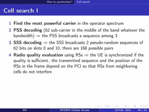
How to synchronize Cell search
Cell search II
5 PBCH decoding rArr MIB (Master Information Block) antennaconfiguration the position of the PBCH does not depend on thebandwidth it is scrambled by a sequence that depends on the PCIThe MIB includes
the bandwidth (in of RBs)PHICH parametersthe frame number
6 PCFICH decoding rArr Number of OFDM symbols dedicated toPDCCHs
7 PDCCH decoding rArr DCI message (with SI-RNTI address) givingthe location of the SIB1 in the PDSCH
8 SIB1 decoding rArr scheduling of other SIBs
9 SIBs (System Information Block) are received on the PDSCH
MC OFDMA Cellular Access 10 Feb 2021 50 81
How to access the network
Section 6
How to access the network
MC OFDMA Cellular Access 10 Feb 2021 51 81
How to access the network Objectives
Objectives
Objectives Establishment or re-establishment of the RRC connectionIntra-system handoversUpon arrival of DL or UL data whereas the UE has lost itssynchronization with the network
2 random access types contention-based conflict-freeContention-based access can be used in all casesConflict-free access for handovers or upon arrival of DL data
PRACH transmission on the uplink then transmission of a CCCHmessage signaling the reason of the access
MC OFDMA Cellular Access 10 Feb 2021 52 81
How to access the network Random access
Contention-based access I
System Information (DL-SCH)(PRACH config PRACH location preamble format sequence list)
Random Access Preamble (RACH)(size of the L2L3 message)
Random Access Response (DL-SCH)(RA-RNTITA temp C-RNTI UL allocation)
CCCH message (UL-SCH)
Collision resolution (DL-SCH)(SDU CCCH)
UEeNB
Figure ndash Contention-based access in LTE
MC OFDMA Cellular Access 10 Feb 2021 53 81
How to access the network Random access
Contention-based access II1) The UE obtains from SIB the PRACH configuration the PRACH
frequency location the preamble format the target received powerand the list of sequences to be used (64 Zadoff-Chu sequencesincluding those reserved to the conflict-free access)
3) The UE chooses at random one sequence among those available4) It sends the preamble on the PRACH with an open loop power
control the UE tries to compensate the path-loss by usingmeasurements made on DL RSs rArr power control makes sequencedetection easier at the BS
Collision several UEs have used the same sequence on the same radioresourceCapture the eNB manages to decode one of the messages in collision
MC OFDMA Cellular Access 10 Feb 2021 54 81
How to access the network Random access
Contention-based access III
5) If there is no answer from the network power ramping (like inCDMA) ie the UE stepwise increases its transmit power
6) The RAR identifies the decoded preamble + provides the timingadvance (TA) + gives an UL allocation + a temporary identity(temporary C-RNTI address)
7) CCCH message on the PUSCH = eg a RRC connection request +temporary C-RNTI
8) Collision resolution the eNB sends a copy of the CCCH message onthe DL The UE that recognizes its message adopts the temporaryC-RNTI (now its address) other UEs leave the procedure
MC OFDMA Cellular Access 10 Feb 2021 55 81
How to access the network Random access
Conflict-free access
The UE has a valid identity (C-RNTI)The eNB sends a (DCI) message on the PDCCH including theZadoff-Chu sequence to be usedCollisions are no more possible no collision resolution phase
MC OFDMA Cellular Access 10 Feb 2021 56 81
How to send and receive data
Section 7
How to send and receive data
MC OFDMA Cellular Access 10 Feb 2021 57 81
How to send and receive data Objectives
Objectives
Objectives Resource allocation tell UEs on which radio resources they will receivedata on the DL-SCH or on which resource they are allowed to transmiton the UL-SCHUE scheduling allocate RBs to UEs as a function of their demand andtheir radio conditionsError control ARQ and HARQ retransmissionsMeasurement feedbacks the UE tells the network the downlinkchannel radio quality or its preferred MIMO precoding matrix
MC OFDMA Cellular Access 10 Feb 2021 58 81
How to send and receive data Resource allocation
Resource allocation I
Location of resources in the sub-frame modulation and coding schemeare signaled in Downlink Control Information (DCI) messagestransmitted on the PDCCHs
Format Description0 Resource allocation on the PUSCH1 PDSCH resource allocation in TM1 TM2 TM71A PDSCH compact allocation and PRACH signature1B PDSCH resource allocation in TM61C PDSCH very compact allocation1D PDSCH compact allocation in TM52 PDSCH compact allocation in TM42A PDSCH compact allocation in TM33 Power control on PUCCHPUSCH (2 bits)3A Power control on PUCCHPUSCH (1 bit)
Table ndash DCI formats
MC OFDMA Cellular Access 10 Feb 2021 59 81
How to send and receive data Resource allocation
Resource allocation II
DCI 0 example A flag to differentiate 1 and 1AA flag for frequency hopping on the PUSCHResource block allocationModulation and coding scheme redundancy version for HARQHARQ new transmission indicatorA power control command for the ULCyclic shift to be applied to ZC sequence for DMRSA CQI request
Every DCI includes a CRC scrambled with a RNTI identityC-RNTI = to address a unique UEP-RNTI = paging messageSI-RNTI = SIBRA-RNTI = random access response
MC OFDMA Cellular Access 10 Feb 2021 60 81
How to send and receive data Scheduling
Scheduling I
Fast (every 1 ms) and adaptive (modulation and coding are adaptedto radio conditions) schedulingDL scheduling decisions are based on CQI feedbacks buffer statusand priorities between logical channelsUL the UE has to feedback its buffer status and radio resource needsby using either the PUCCH (scheduling request) or the UL-SCH (MACcontrol messages)
MC OFDMA Cellular Access 10 Feb 2021 61 81
How to send and receive data Scheduling
Scheduling IIAlgorithm LTE offers a new degree of freedom wrt HSPA thepossibility to schedule users on different radio blocks
Channel q
ualit
y
fPRB1 PRB2 PRB3 PRB4 PRB5
Channel UE1
Channel UE2
Channel UE3
Scheduling decisions UE2 UE3 UE1 UE3 UE2
Figure ndash Frequency Dependent Packet Scheduling (FDPS) in LTE
MC OFDMA Cellular Access 10 Feb 2021 62 81
How to send and receive data Scheduling
Scheduling III
f
t
Syste
m b
an
dw
idth
Sub-frame (1 ms)
f
t
Comb onesub-carrieris used outof two
(a) SRS transmission without frequency hopping
(b) SRS transmission with frequency hopping
Figure ndash Sounding Reference Signals (SRS) transmissions
The eNB estimates the channel quality on the UL thanks to SRS
SRS is transmitted on a bandwidth much larger than the one allocated to UEtransmissions
SRS from different UEs are multiplexed in time (different sub-frames and periods)frequency (different sets of RBs oddeven sub-carriers) or code (differentsequences)
MC OFDMA Cellular Access 10 Feb 2021 63 81
How to send and receive data Error control
ARQ and HARQ
Like in HSPA HARQ is in the MAC layer and ARQ in the RLCHARQ DL sequence number is signaled in the PDCCH ACKNACKare fed back in the PUSCH (with data) or in the PUCCHHARQ UL ACKNACK transmitted in the PHICHARQ Transparent Mode (TM) (no header no segmentation orconcatenation) Unacknowledged (UM) (header with sequencenumber) Acknowledged (AM) (ARQ)
MC OFDMA Cellular Access 10 Feb 2021 64 81
How to send and receive data Measurements
Measurements
Radio quality measurements CQI (Channel Quality Indicator) modulation (QPSK 16-QAM or64-QAM) and transport block maximum size that a UE can receivewith a BLERlt10 (Block Error Rate)RI (Rank Indicator) rank of the DL transmission = number ofindependent spatial layers that can be usedPMI (Precoding Matrix Indicator) UE preferred precoding matrix Wfor transmission modes with closed loop
Physical channels PUSCH for aperiodic feedbacks with data transmissionPUCCH for periodic feedbacks
MC OFDMA Cellular Access 10 Feb 2021 65 81
Terminals categories
Section 8
Terminals categories
MC OFDMA Cellular Access 10 Feb 2021 66 81
Terminals categories
Terminals categories
Caracteristics Cat 1 Cat 2 Cat 3 Cat 4 Cat 5Max number ofbits per TTI (DL) 10296 51024 102048 150752 299552
Max number ofbits per TTI (UL) 5160 25456 51024 51024 75376
Max data rate(DL) 10 Mbps 50 Mbps 100 Mbps 150 Mbps 300 Mbps
Max data rate(UL) 5 Mbps 25 Mbps 50 Mbps 50 Mbps 75 Mbps
64 QAM (UL) No No No No YesMIMO (DL) Option 2times 2 2times 2 2times 2 4times 4
Table ndash Terminal categories in LTE
For example the Semsong S5 is cat 4 the Semsong S6 is cat 6 (Release 1030050 Mbps) the Semsong S8 is cat1613 (Release 12 1050150 Mbps MIMO4x4 256-QAM 5CA) Semsong S10 is cat 2013 (2000 Mbps up to 8 MIMOlayers 256-QAM 7CA)
MC OFDMA Cellular Access 10 Feb 2021 67 81
Summary on channels
Section 9
Summary on channels
MC OFDMA Cellular Access 10 Feb 2021 68 81
Summary on channels
Physical channels DL I
PDSCH (Physical Downlink Shared Ch) physical shared channel for data
RS (Reference Signals) pilots required to estimate radio quality and toallow decoding on the DL
SS (Synchronization Signals) = PSS (Primary)+SSS (Secondary) for timeand frequency synchronization
PBCH (Physical Broadcast Ch) beacon MIB transmission
PCFICH (Physical Control Format Indicator Ch) tell the UEs how manyOFDM symbols are dedicated to the control part of the sub-frame (CFI)
PDCCH (Physical Downlink Control Ch) control informations (DCI resource allocation UE identity HARQ information MIMO etc)
PHICH (Physical Hybrid ARQ Indicator Ch) ACKNACK responses toHARQ transmissions from a UE (HI)
MC OFDMA Cellular Access 10 Feb 2021 69 81
Summary on channels
Physical channels UL I
In UL a UE is not able to multiplex different physical channels in the frequencydomain because of SC-FDMA limitation rArr time multiplexing is required
DMRS (Demodulation Reference Signal) used by the eNB to estimate thechannel and make radio quality measurements on the signal transmitted by theUE DMRS are sent in conjunction with PUCCH and PUSCH
SRS (Sounding Reference Signal) pilots used by the scheduler for the radioquality estimation on a bandwidth larger than the one allocated to the UE
PUCCH (Physical Uplink Control Ch) control informations UCI includingchannel quality (CQI) MIMO (closed loop) or HARQ (ACKNACK) informations
PUSCH (Physical Uplink Shared Ch) shared physical channels for data andcontrol
If a UE has data to transmit it uses the PUSCH for data and control Otherwiseit uses the PUCCH for the control
MC OFDMA Cellular Access 10 Feb 2021 70 81
Summary on channels
Transport channels DL
DL-SCH (DL Shared Ch) shared channel for data associated toPDSCHPCH (Paging Ch) broadcast of paging messages on the PDSCHBCH (Broadcast Ch) broadcast of system informations (SIBs) onthe PBCH and on the PDSCHDCI (DL Control Indicator) control information transmitted on thePDCCHs (transport format resource allocation HARQ and MIMOinformations power control commands)CFI (Control Format Indicator) number of OFDM symbols (12 or 3)used by PDCCHs at the beginning of every sub-frame CFI is sent onthe PCFICHHI (HARQ Indicator) ACK or NACK in response to a transmissionon the UL-SCH HI is transmitted on the PHICH
MC OFDMA Cellular Access 10 Feb 2021 71 81
Summary on channels
transport channels UL
RACH (Random Access Ch) random accessUL-SCH (UL Share Ch) shared channel for data and controlassociated to PUSCH User data and control informations aremultiplexed in time and frequency on the PUSCHUCI (UL Control Indicator) control information transmitted by thePUCCH (channel quality CQI closed loop MIMO informationsPMIRI ACKNACK of HARQ scheduling request)
MC OFDMA Cellular Access 10 Feb 2021 72 81
Summary on channels
Logical channels
Logical channel Type Description LinkBCCH Control System information DLPCCH Control Paging DLCCCH Control Control without RRC conn ULDLDCCH Controcircle Dedicated control ULDLDTCH Traffic user plane ULDL
Table ndash Logical channels in LTE DL and UL
BCCH (Broadcast COntrol Ch) system information associated to BCH for theMIB and DL-SCH for the SIBs
PCCH (Paging Control Ch) paging associated to PCH
CCCH (Common Control Ch) control messages between the network and UEswithout RRC connection associated to DL-SCH and UL-SCH
DCCH (Dedicated Control Ch) control messages between the network and UEswith RRC connection associated to DL-SCH and UL-SCH
MC OFDMA Cellular Access 10 Feb 2021 73 81
Conclusion
Section 10
Conclusion
MC OFDMA Cellular Access 10 Feb 2021 74 81
Conclusion
Conclusion
LTE A brand new standardA certain simplicity that is reminiscent of GSMSimilarities with 3G (channels HARQ MAC RLC etc)New features (MIMO MU-MIMO multi-carrier transmissions)
After LTE LTE-A R13 frozen in Mar 2016 (LTE Pro) R14 on goingR15 is called 5G New Radio (NR) and is the first 5G releasePeak rates of the order of 1GbpsCarrier aggregation discontinuous resource allocation on the ULMIMO 8times8 relays HetNets CoMP Self-Organized NetworksMBMS NB-IoT etc
MC OFDMA Cellular Access 10 Feb 2021 75 81
Conclusion
References I
3GPPTechnical Specification 36211 Physical channels and modulationDec 2009
3GPPTechnical Specification 36300 Evolved Universal Terrestrial RadioAccess (E-UTRA) and Evolved Universal Terrestrial Radio AccessNetwork (E-UTRAN) Overall description Apr 2010
3GPPTechnical Specification 36104 Base Station (BS) radio transmissionand reception Jun 2011
MC OFDMA Cellular Access 10 Feb 2021 76 81
Conclusion
References II
S M AlamoutiA simple transmit diversity technique for wireless communicationsIEEE J on Selected Areas in Communications 16(8) 1451ndash1458 Oct1998
MC OFDMA Cellular Access 10 Feb 2021 77 81
Conclusion
Acronyms I
AM ARQ Acknowledged ModeARQ Automatic Repeat on RequestBCCH Broadcast Control ChannelBCH Broadcast ChannelBLER Block Error RateBPSK Binary Phase Shift KeyingBS Base Station
CCCH Common Control ChannelCDMA Code Division Multiple AccessCFI Control Format Indocator
CoMP Coordinated Multi-PointCQI Channel Quality IndicatorCRC Cyclic Redundancy CodeD2D Device to DeviceDCCH Dedicated Control ChannelDCI Downlink Control InformationDL Downlink
DL-SCH Downlink Shared ChannelDMRS Demodulation Reference SignalDTCH Dedicated Traffic ChanneleNB eNode-BEPC Evolved Packet Core
E-UTRAN Evolved UTRANFDD Frequency Division DuplexFDPS Frequency Dependent Packet SchedulingFFT Fast Fourier TransformGSM Groupe Speacutecial MobileHARQ Hybrid Automatic Repeat on Request
MC OFDMA Cellular Access 10 Feb 2021 78 81
Conclusion
Acronyms IIHI HARQ Indicator
HSPA High Speed Packet AccessHSDPA High Speed Downlink Packet AccessHSPA High Speed Uplink Packet AccessICI Inter-Carrier InterferenceIFFT Inverse Fast Fourier TransformIMT International Mobile TelecommunicationsISI Inter-Symbol InterferenceLTE Long Term EvolutionMAC Medium Access ControlMBMS Multimedia Broadcast Multicast ServiceMIB Master Information BlockMIMO Multiple Input Multiple OutputMME Mobility Management Entity
MU-MIMO Multi-User MIMONAS Non Access StratumOFDM Orthogonal Frequency Division MultiplexOFDMA Orthogonal Frequency Division Multiple AccessPAPR Peak to Average Power RatioPBCH Physical Broadcast ChannelPCFICH Physical Control Format Indicator ChannelPCCH Paging Control ChannelPCH Paging ChannelPCI Physical Cell Identifier
PDCCH Physical Downlink Control ChannelPDCP Packet Data Convergence ProtocolPDSCH Physical Downlink Shared ChannelPDU Protocol Data Unit
MC OFDMA Cellular Access 10 Feb 2021 79 81
Conclusion
Acronyms IIIPHICH Physical Hybrid ARQ Indicator ChannelPMI Precoding Matrix IndicatorPSS Primary Synchronization Signal
PUCCH Physical Uplink Control ChannelPUSCH Physical Uplink Shared ChannelQAM Qadrature Amplitude ModulationQPSK Quadrature Phase Shift KeyingRACH Random Access ChannelRAR Random Access ResponseRB Resource BlockRE Resource ElementRI Rank IndicatorRLC Radio Link ControlRNC Radio Network ControllerRNTI Radio Network Temporary IdentifierROHC Robust Header CompressionRRC Radio Resource ControlRS Reference Signal
SC-FDMA Single Carrier Frequency Division Multiple AccessSDU Service Data UnitSFBC Space-Time Block CodeSGW Serving GatewaySIB System Information BlockSISO Single Input Single OutputSNR Signal to Noise RatioSRS Sounding Reference SignalSSS Secondary Synchronization SignalTA Timing Advance
MC OFDMA Cellular Access 10 Feb 2021 80 81
Conclusion
Acronyms IV
TDD Time Division DuplexTM Transmission ModeTM ARQ Transparent ModeTTI Transmission Time IntervalUCI Uplink Control InformationUE User EquipmentUM ARQ Unacknowledged Mode
UMTS Universal Mobile Telecommunications SystemUL Uplink
UL-SCH Uplink Shared ChannelUTRAN UMTS Terrestrial Radio Access NetworkWCDMA Wideband Code Division Multiple Access
MC OFDMA Cellular Access 10 Feb 2021 81 81

How to access the network
Section 6
How to access the network
MC OFDMA Cellular Access 10 Feb 2021 51 81
How to access the network Objectives
Objectives
Objectives Establishment or re-establishment of the RRC connectionIntra-system handoversUpon arrival of DL or UL data whereas the UE has lost itssynchronization with the network
2 random access types contention-based conflict-freeContention-based access can be used in all casesConflict-free access for handovers or upon arrival of DL data
PRACH transmission on the uplink then transmission of a CCCHmessage signaling the reason of the access
MC OFDMA Cellular Access 10 Feb 2021 52 81
How to access the network Random access
Contention-based access I
System Information (DL-SCH)(PRACH config PRACH location preamble format sequence list)
Random Access Preamble (RACH)(size of the L2L3 message)
Random Access Response (DL-SCH)(RA-RNTITA temp C-RNTI UL allocation)
CCCH message (UL-SCH)
Collision resolution (DL-SCH)(SDU CCCH)
UEeNB
Figure ndash Contention-based access in LTE
MC OFDMA Cellular Access 10 Feb 2021 53 81
How to access the network Random access
Contention-based access II1) The UE obtains from SIB the PRACH configuration the PRACH
frequency location the preamble format the target received powerand the list of sequences to be used (64 Zadoff-Chu sequencesincluding those reserved to the conflict-free access)
3) The UE chooses at random one sequence among those available4) It sends the preamble on the PRACH with an open loop power
control the UE tries to compensate the path-loss by usingmeasurements made on DL RSs rArr power control makes sequencedetection easier at the BS
Collision several UEs have used the same sequence on the same radioresourceCapture the eNB manages to decode one of the messages in collision
MC OFDMA Cellular Access 10 Feb 2021 54 81
How to access the network Random access
Contention-based access III
5) If there is no answer from the network power ramping (like inCDMA) ie the UE stepwise increases its transmit power
6) The RAR identifies the decoded preamble + provides the timingadvance (TA) + gives an UL allocation + a temporary identity(temporary C-RNTI address)
7) CCCH message on the PUSCH = eg a RRC connection request +temporary C-RNTI
8) Collision resolution the eNB sends a copy of the CCCH message onthe DL The UE that recognizes its message adopts the temporaryC-RNTI (now its address) other UEs leave the procedure
MC OFDMA Cellular Access 10 Feb 2021 55 81
How to access the network Random access
Conflict-free access
The UE has a valid identity (C-RNTI)The eNB sends a (DCI) message on the PDCCH including theZadoff-Chu sequence to be usedCollisions are no more possible no collision resolution phase
MC OFDMA Cellular Access 10 Feb 2021 56 81
How to send and receive data
Section 7
How to send and receive data
MC OFDMA Cellular Access 10 Feb 2021 57 81
How to send and receive data Objectives
Objectives
Objectives Resource allocation tell UEs on which radio resources they will receivedata on the DL-SCH or on which resource they are allowed to transmiton the UL-SCHUE scheduling allocate RBs to UEs as a function of their demand andtheir radio conditionsError control ARQ and HARQ retransmissionsMeasurement feedbacks the UE tells the network the downlinkchannel radio quality or its preferred MIMO precoding matrix
MC OFDMA Cellular Access 10 Feb 2021 58 81
How to send and receive data Resource allocation
Resource allocation I
Location of resources in the sub-frame modulation and coding schemeare signaled in Downlink Control Information (DCI) messagestransmitted on the PDCCHs
Format Description0 Resource allocation on the PUSCH1 PDSCH resource allocation in TM1 TM2 TM71A PDSCH compact allocation and PRACH signature1B PDSCH resource allocation in TM61C PDSCH very compact allocation1D PDSCH compact allocation in TM52 PDSCH compact allocation in TM42A PDSCH compact allocation in TM33 Power control on PUCCHPUSCH (2 bits)3A Power control on PUCCHPUSCH (1 bit)
Table ndash DCI formats
MC OFDMA Cellular Access 10 Feb 2021 59 81
How to send and receive data Resource allocation
Resource allocation II
DCI 0 example A flag to differentiate 1 and 1AA flag for frequency hopping on the PUSCHResource block allocationModulation and coding scheme redundancy version for HARQHARQ new transmission indicatorA power control command for the ULCyclic shift to be applied to ZC sequence for DMRSA CQI request
Every DCI includes a CRC scrambled with a RNTI identityC-RNTI = to address a unique UEP-RNTI = paging messageSI-RNTI = SIBRA-RNTI = random access response
MC OFDMA Cellular Access 10 Feb 2021 60 81
How to send and receive data Scheduling
Scheduling I
Fast (every 1 ms) and adaptive (modulation and coding are adaptedto radio conditions) schedulingDL scheduling decisions are based on CQI feedbacks buffer statusand priorities between logical channelsUL the UE has to feedback its buffer status and radio resource needsby using either the PUCCH (scheduling request) or the UL-SCH (MACcontrol messages)
MC OFDMA Cellular Access 10 Feb 2021 61 81
How to send and receive data Scheduling
Scheduling IIAlgorithm LTE offers a new degree of freedom wrt HSPA thepossibility to schedule users on different radio blocks
Channel q
ualit
y
fPRB1 PRB2 PRB3 PRB4 PRB5
Channel UE1
Channel UE2
Channel UE3
Scheduling decisions UE2 UE3 UE1 UE3 UE2
Figure ndash Frequency Dependent Packet Scheduling (FDPS) in LTE
MC OFDMA Cellular Access 10 Feb 2021 62 81
How to send and receive data Scheduling
Scheduling III
f
t
Syste
m b
an
dw
idth
Sub-frame (1 ms)
f
t
Comb onesub-carrieris used outof two
(a) SRS transmission without frequency hopping
(b) SRS transmission with frequency hopping
Figure ndash Sounding Reference Signals (SRS) transmissions
The eNB estimates the channel quality on the UL thanks to SRS
SRS is transmitted on a bandwidth much larger than the one allocated to UEtransmissions
SRS from different UEs are multiplexed in time (different sub-frames and periods)frequency (different sets of RBs oddeven sub-carriers) or code (differentsequences)
MC OFDMA Cellular Access 10 Feb 2021 63 81
How to send and receive data Error control
ARQ and HARQ
Like in HSPA HARQ is in the MAC layer and ARQ in the RLCHARQ DL sequence number is signaled in the PDCCH ACKNACKare fed back in the PUSCH (with data) or in the PUCCHHARQ UL ACKNACK transmitted in the PHICHARQ Transparent Mode (TM) (no header no segmentation orconcatenation) Unacknowledged (UM) (header with sequencenumber) Acknowledged (AM) (ARQ)
MC OFDMA Cellular Access 10 Feb 2021 64 81
How to send and receive data Measurements
Measurements
Radio quality measurements CQI (Channel Quality Indicator) modulation (QPSK 16-QAM or64-QAM) and transport block maximum size that a UE can receivewith a BLERlt10 (Block Error Rate)RI (Rank Indicator) rank of the DL transmission = number ofindependent spatial layers that can be usedPMI (Precoding Matrix Indicator) UE preferred precoding matrix Wfor transmission modes with closed loop
Physical channels PUSCH for aperiodic feedbacks with data transmissionPUCCH for periodic feedbacks
MC OFDMA Cellular Access 10 Feb 2021 65 81
Terminals categories
Section 8
Terminals categories
MC OFDMA Cellular Access 10 Feb 2021 66 81
Terminals categories
Terminals categories
Caracteristics Cat 1 Cat 2 Cat 3 Cat 4 Cat 5Max number ofbits per TTI (DL) 10296 51024 102048 150752 299552
Max number ofbits per TTI (UL) 5160 25456 51024 51024 75376
Max data rate(DL) 10 Mbps 50 Mbps 100 Mbps 150 Mbps 300 Mbps
Max data rate(UL) 5 Mbps 25 Mbps 50 Mbps 50 Mbps 75 Mbps
64 QAM (UL) No No No No YesMIMO (DL) Option 2times 2 2times 2 2times 2 4times 4
Table ndash Terminal categories in LTE
For example the Semsong S5 is cat 4 the Semsong S6 is cat 6 (Release 1030050 Mbps) the Semsong S8 is cat1613 (Release 12 1050150 Mbps MIMO4x4 256-QAM 5CA) Semsong S10 is cat 2013 (2000 Mbps up to 8 MIMOlayers 256-QAM 7CA)
MC OFDMA Cellular Access 10 Feb 2021 67 81
Summary on channels
Section 9
Summary on channels
MC OFDMA Cellular Access 10 Feb 2021 68 81
Summary on channels
Physical channels DL I
PDSCH (Physical Downlink Shared Ch) physical shared channel for data
RS (Reference Signals) pilots required to estimate radio quality and toallow decoding on the DL
SS (Synchronization Signals) = PSS (Primary)+SSS (Secondary) for timeand frequency synchronization
PBCH (Physical Broadcast Ch) beacon MIB transmission
PCFICH (Physical Control Format Indicator Ch) tell the UEs how manyOFDM symbols are dedicated to the control part of the sub-frame (CFI)
PDCCH (Physical Downlink Control Ch) control informations (DCI resource allocation UE identity HARQ information MIMO etc)
PHICH (Physical Hybrid ARQ Indicator Ch) ACKNACK responses toHARQ transmissions from a UE (HI)
MC OFDMA Cellular Access 10 Feb 2021 69 81
Summary on channels
Physical channels UL I
In UL a UE is not able to multiplex different physical channels in the frequencydomain because of SC-FDMA limitation rArr time multiplexing is required
DMRS (Demodulation Reference Signal) used by the eNB to estimate thechannel and make radio quality measurements on the signal transmitted by theUE DMRS are sent in conjunction with PUCCH and PUSCH
SRS (Sounding Reference Signal) pilots used by the scheduler for the radioquality estimation on a bandwidth larger than the one allocated to the UE
PUCCH (Physical Uplink Control Ch) control informations UCI includingchannel quality (CQI) MIMO (closed loop) or HARQ (ACKNACK) informations
PUSCH (Physical Uplink Shared Ch) shared physical channels for data andcontrol
If a UE has data to transmit it uses the PUSCH for data and control Otherwiseit uses the PUCCH for the control
MC OFDMA Cellular Access 10 Feb 2021 70 81
Summary on channels
Transport channels DL
DL-SCH (DL Shared Ch) shared channel for data associated toPDSCHPCH (Paging Ch) broadcast of paging messages on the PDSCHBCH (Broadcast Ch) broadcast of system informations (SIBs) onthe PBCH and on the PDSCHDCI (DL Control Indicator) control information transmitted on thePDCCHs (transport format resource allocation HARQ and MIMOinformations power control commands)CFI (Control Format Indicator) number of OFDM symbols (12 or 3)used by PDCCHs at the beginning of every sub-frame CFI is sent onthe PCFICHHI (HARQ Indicator) ACK or NACK in response to a transmissionon the UL-SCH HI is transmitted on the PHICH
MC OFDMA Cellular Access 10 Feb 2021 71 81
Summary on channels
transport channels UL
RACH (Random Access Ch) random accessUL-SCH (UL Share Ch) shared channel for data and controlassociated to PUSCH User data and control informations aremultiplexed in time and frequency on the PUSCHUCI (UL Control Indicator) control information transmitted by thePUCCH (channel quality CQI closed loop MIMO informationsPMIRI ACKNACK of HARQ scheduling request)
MC OFDMA Cellular Access 10 Feb 2021 72 81
Summary on channels
Logical channels
Logical channel Type Description LinkBCCH Control System information DLPCCH Control Paging DLCCCH Control Control without RRC conn ULDLDCCH Controcircle Dedicated control ULDLDTCH Traffic user plane ULDL
Table ndash Logical channels in LTE DL and UL
BCCH (Broadcast COntrol Ch) system information associated to BCH for theMIB and DL-SCH for the SIBs
PCCH (Paging Control Ch) paging associated to PCH
CCCH (Common Control Ch) control messages between the network and UEswithout RRC connection associated to DL-SCH and UL-SCH
DCCH (Dedicated Control Ch) control messages between the network and UEswith RRC connection associated to DL-SCH and UL-SCH
MC OFDMA Cellular Access 10 Feb 2021 73 81
Conclusion
Section 10
Conclusion
MC OFDMA Cellular Access 10 Feb 2021 74 81
Conclusion
Conclusion
LTE A brand new standardA certain simplicity that is reminiscent of GSMSimilarities with 3G (channels HARQ MAC RLC etc)New features (MIMO MU-MIMO multi-carrier transmissions)
After LTE LTE-A R13 frozen in Mar 2016 (LTE Pro) R14 on goingR15 is called 5G New Radio (NR) and is the first 5G releasePeak rates of the order of 1GbpsCarrier aggregation discontinuous resource allocation on the ULMIMO 8times8 relays HetNets CoMP Self-Organized NetworksMBMS NB-IoT etc
MC OFDMA Cellular Access 10 Feb 2021 75 81
Conclusion
References I
3GPPTechnical Specification 36211 Physical channels and modulationDec 2009
3GPPTechnical Specification 36300 Evolved Universal Terrestrial RadioAccess (E-UTRA) and Evolved Universal Terrestrial Radio AccessNetwork (E-UTRAN) Overall description Apr 2010
3GPPTechnical Specification 36104 Base Station (BS) radio transmissionand reception Jun 2011
MC OFDMA Cellular Access 10 Feb 2021 76 81
Conclusion
References II
S M AlamoutiA simple transmit diversity technique for wireless communicationsIEEE J on Selected Areas in Communications 16(8) 1451ndash1458 Oct1998
MC OFDMA Cellular Access 10 Feb 2021 77 81
Conclusion
Acronyms I
AM ARQ Acknowledged ModeARQ Automatic Repeat on RequestBCCH Broadcast Control ChannelBCH Broadcast ChannelBLER Block Error RateBPSK Binary Phase Shift KeyingBS Base Station
CCCH Common Control ChannelCDMA Code Division Multiple AccessCFI Control Format Indocator
CoMP Coordinated Multi-PointCQI Channel Quality IndicatorCRC Cyclic Redundancy CodeD2D Device to DeviceDCCH Dedicated Control ChannelDCI Downlink Control InformationDL Downlink
DL-SCH Downlink Shared ChannelDMRS Demodulation Reference SignalDTCH Dedicated Traffic ChanneleNB eNode-BEPC Evolved Packet Core
E-UTRAN Evolved UTRANFDD Frequency Division DuplexFDPS Frequency Dependent Packet SchedulingFFT Fast Fourier TransformGSM Groupe Speacutecial MobileHARQ Hybrid Automatic Repeat on Request
MC OFDMA Cellular Access 10 Feb 2021 78 81
Conclusion
Acronyms IIHI HARQ Indicator
HSPA High Speed Packet AccessHSDPA High Speed Downlink Packet AccessHSPA High Speed Uplink Packet AccessICI Inter-Carrier InterferenceIFFT Inverse Fast Fourier TransformIMT International Mobile TelecommunicationsISI Inter-Symbol InterferenceLTE Long Term EvolutionMAC Medium Access ControlMBMS Multimedia Broadcast Multicast ServiceMIB Master Information BlockMIMO Multiple Input Multiple OutputMME Mobility Management Entity
MU-MIMO Multi-User MIMONAS Non Access StratumOFDM Orthogonal Frequency Division MultiplexOFDMA Orthogonal Frequency Division Multiple AccessPAPR Peak to Average Power RatioPBCH Physical Broadcast ChannelPCFICH Physical Control Format Indicator ChannelPCCH Paging Control ChannelPCH Paging ChannelPCI Physical Cell Identifier
PDCCH Physical Downlink Control ChannelPDCP Packet Data Convergence ProtocolPDSCH Physical Downlink Shared ChannelPDU Protocol Data Unit
MC OFDMA Cellular Access 10 Feb 2021 79 81
Conclusion
Acronyms IIIPHICH Physical Hybrid ARQ Indicator ChannelPMI Precoding Matrix IndicatorPSS Primary Synchronization Signal
PUCCH Physical Uplink Control ChannelPUSCH Physical Uplink Shared ChannelQAM Qadrature Amplitude ModulationQPSK Quadrature Phase Shift KeyingRACH Random Access ChannelRAR Random Access ResponseRB Resource BlockRE Resource ElementRI Rank IndicatorRLC Radio Link ControlRNC Radio Network ControllerRNTI Radio Network Temporary IdentifierROHC Robust Header CompressionRRC Radio Resource ControlRS Reference Signal
SC-FDMA Single Carrier Frequency Division Multiple AccessSDU Service Data UnitSFBC Space-Time Block CodeSGW Serving GatewaySIB System Information BlockSISO Single Input Single OutputSNR Signal to Noise RatioSRS Sounding Reference SignalSSS Secondary Synchronization SignalTA Timing Advance
MC OFDMA Cellular Access 10 Feb 2021 80 81
Conclusion
Acronyms IV
TDD Time Division DuplexTM Transmission ModeTM ARQ Transparent ModeTTI Transmission Time IntervalUCI Uplink Control InformationUE User EquipmentUM ARQ Unacknowledged Mode
UMTS Universal Mobile Telecommunications SystemUL Uplink
UL-SCH Uplink Shared ChannelUTRAN UMTS Terrestrial Radio Access NetworkWCDMA Wideband Code Division Multiple Access
MC OFDMA Cellular Access 10 Feb 2021 81 81

How to access the network Random access
Contention-based access I
System Information (DL-SCH)(PRACH config PRACH location preamble format sequence list)
Random Access Preamble (RACH)(size of the L2L3 message)
Random Access Response (DL-SCH)(RA-RNTITA temp C-RNTI UL allocation)
CCCH message (UL-SCH)
Collision resolution (DL-SCH)(SDU CCCH)
UEeNB
Figure ndash Contention-based access in LTE
MC OFDMA Cellular Access 10 Feb 2021 53 81
How to access the network Random access
Contention-based access II1) The UE obtains from SIB the PRACH configuration the PRACH
frequency location the preamble format the target received powerand the list of sequences to be used (64 Zadoff-Chu sequencesincluding those reserved to the conflict-free access)
3) The UE chooses at random one sequence among those available4) It sends the preamble on the PRACH with an open loop power
control the UE tries to compensate the path-loss by usingmeasurements made on DL RSs rArr power control makes sequencedetection easier at the BS
Collision several UEs have used the same sequence on the same radioresourceCapture the eNB manages to decode one of the messages in collision
MC OFDMA Cellular Access 10 Feb 2021 54 81
How to access the network Random access
Contention-based access III
5) If there is no answer from the network power ramping (like inCDMA) ie the UE stepwise increases its transmit power
6) The RAR identifies the decoded preamble + provides the timingadvance (TA) + gives an UL allocation + a temporary identity(temporary C-RNTI address)
7) CCCH message on the PUSCH = eg a RRC connection request +temporary C-RNTI
8) Collision resolution the eNB sends a copy of the CCCH message onthe DL The UE that recognizes its message adopts the temporaryC-RNTI (now its address) other UEs leave the procedure
MC OFDMA Cellular Access 10 Feb 2021 55 81
How to access the network Random access
Conflict-free access
The UE has a valid identity (C-RNTI)The eNB sends a (DCI) message on the PDCCH including theZadoff-Chu sequence to be usedCollisions are no more possible no collision resolution phase
MC OFDMA Cellular Access 10 Feb 2021 56 81
How to send and receive data
Section 7
How to send and receive data
MC OFDMA Cellular Access 10 Feb 2021 57 81
How to send and receive data Objectives
Objectives
Objectives Resource allocation tell UEs on which radio resources they will receivedata on the DL-SCH or on which resource they are allowed to transmiton the UL-SCHUE scheduling allocate RBs to UEs as a function of their demand andtheir radio conditionsError control ARQ and HARQ retransmissionsMeasurement feedbacks the UE tells the network the downlinkchannel radio quality or its preferred MIMO precoding matrix
MC OFDMA Cellular Access 10 Feb 2021 58 81
How to send and receive data Resource allocation
Resource allocation I
Location of resources in the sub-frame modulation and coding schemeare signaled in Downlink Control Information (DCI) messagestransmitted on the PDCCHs
Format Description0 Resource allocation on the PUSCH1 PDSCH resource allocation in TM1 TM2 TM71A PDSCH compact allocation and PRACH signature1B PDSCH resource allocation in TM61C PDSCH very compact allocation1D PDSCH compact allocation in TM52 PDSCH compact allocation in TM42A PDSCH compact allocation in TM33 Power control on PUCCHPUSCH (2 bits)3A Power control on PUCCHPUSCH (1 bit)
Table ndash DCI formats
MC OFDMA Cellular Access 10 Feb 2021 59 81
How to send and receive data Resource allocation
Resource allocation II
DCI 0 example A flag to differentiate 1 and 1AA flag for frequency hopping on the PUSCHResource block allocationModulation and coding scheme redundancy version for HARQHARQ new transmission indicatorA power control command for the ULCyclic shift to be applied to ZC sequence for DMRSA CQI request
Every DCI includes a CRC scrambled with a RNTI identityC-RNTI = to address a unique UEP-RNTI = paging messageSI-RNTI = SIBRA-RNTI = random access response
MC OFDMA Cellular Access 10 Feb 2021 60 81
How to send and receive data Scheduling
Scheduling I
Fast (every 1 ms) and adaptive (modulation and coding are adaptedto radio conditions) schedulingDL scheduling decisions are based on CQI feedbacks buffer statusand priorities between logical channelsUL the UE has to feedback its buffer status and radio resource needsby using either the PUCCH (scheduling request) or the UL-SCH (MACcontrol messages)
MC OFDMA Cellular Access 10 Feb 2021 61 81
How to send and receive data Scheduling
Scheduling IIAlgorithm LTE offers a new degree of freedom wrt HSPA thepossibility to schedule users on different radio blocks
Channel q
ualit
y
fPRB1 PRB2 PRB3 PRB4 PRB5
Channel UE1
Channel UE2
Channel UE3
Scheduling decisions UE2 UE3 UE1 UE3 UE2
Figure ndash Frequency Dependent Packet Scheduling (FDPS) in LTE
MC OFDMA Cellular Access 10 Feb 2021 62 81
How to send and receive data Scheduling
Scheduling III
f
t
Syste
m b
an
dw
idth
Sub-frame (1 ms)
f
t
Comb onesub-carrieris used outof two
(a) SRS transmission without frequency hopping
(b) SRS transmission with frequency hopping
Figure ndash Sounding Reference Signals (SRS) transmissions
The eNB estimates the channel quality on the UL thanks to SRS
SRS is transmitted on a bandwidth much larger than the one allocated to UEtransmissions
SRS from different UEs are multiplexed in time (different sub-frames and periods)frequency (different sets of RBs oddeven sub-carriers) or code (differentsequences)
MC OFDMA Cellular Access 10 Feb 2021 63 81
How to send and receive data Error control
ARQ and HARQ
Like in HSPA HARQ is in the MAC layer and ARQ in the RLCHARQ DL sequence number is signaled in the PDCCH ACKNACKare fed back in the PUSCH (with data) or in the PUCCHHARQ UL ACKNACK transmitted in the PHICHARQ Transparent Mode (TM) (no header no segmentation orconcatenation) Unacknowledged (UM) (header with sequencenumber) Acknowledged (AM) (ARQ)
MC OFDMA Cellular Access 10 Feb 2021 64 81
How to send and receive data Measurements
Measurements
Radio quality measurements CQI (Channel Quality Indicator) modulation (QPSK 16-QAM or64-QAM) and transport block maximum size that a UE can receivewith a BLERlt10 (Block Error Rate)RI (Rank Indicator) rank of the DL transmission = number ofindependent spatial layers that can be usedPMI (Precoding Matrix Indicator) UE preferred precoding matrix Wfor transmission modes with closed loop
Physical channels PUSCH for aperiodic feedbacks with data transmissionPUCCH for periodic feedbacks
MC OFDMA Cellular Access 10 Feb 2021 65 81
Terminals categories
Section 8
Terminals categories
MC OFDMA Cellular Access 10 Feb 2021 66 81
Terminals categories
Terminals categories
Caracteristics Cat 1 Cat 2 Cat 3 Cat 4 Cat 5Max number ofbits per TTI (DL) 10296 51024 102048 150752 299552
Max number ofbits per TTI (UL) 5160 25456 51024 51024 75376
Max data rate(DL) 10 Mbps 50 Mbps 100 Mbps 150 Mbps 300 Mbps
Max data rate(UL) 5 Mbps 25 Mbps 50 Mbps 50 Mbps 75 Mbps
64 QAM (UL) No No No No YesMIMO (DL) Option 2times 2 2times 2 2times 2 4times 4
Table ndash Terminal categories in LTE
For example the Semsong S5 is cat 4 the Semsong S6 is cat 6 (Release 1030050 Mbps) the Semsong S8 is cat1613 (Release 12 1050150 Mbps MIMO4x4 256-QAM 5CA) Semsong S10 is cat 2013 (2000 Mbps up to 8 MIMOlayers 256-QAM 7CA)
MC OFDMA Cellular Access 10 Feb 2021 67 81
Summary on channels
Section 9
Summary on channels
MC OFDMA Cellular Access 10 Feb 2021 68 81
Summary on channels
Physical channels DL I
PDSCH (Physical Downlink Shared Ch) physical shared channel for data
RS (Reference Signals) pilots required to estimate radio quality and toallow decoding on the DL
SS (Synchronization Signals) = PSS (Primary)+SSS (Secondary) for timeand frequency synchronization
PBCH (Physical Broadcast Ch) beacon MIB transmission
PCFICH (Physical Control Format Indicator Ch) tell the UEs how manyOFDM symbols are dedicated to the control part of the sub-frame (CFI)
PDCCH (Physical Downlink Control Ch) control informations (DCI resource allocation UE identity HARQ information MIMO etc)
PHICH (Physical Hybrid ARQ Indicator Ch) ACKNACK responses toHARQ transmissions from a UE (HI)
MC OFDMA Cellular Access 10 Feb 2021 69 81
Summary on channels
Physical channels UL I
In UL a UE is not able to multiplex different physical channels in the frequencydomain because of SC-FDMA limitation rArr time multiplexing is required
DMRS (Demodulation Reference Signal) used by the eNB to estimate thechannel and make radio quality measurements on the signal transmitted by theUE DMRS are sent in conjunction with PUCCH and PUSCH
SRS (Sounding Reference Signal) pilots used by the scheduler for the radioquality estimation on a bandwidth larger than the one allocated to the UE
PUCCH (Physical Uplink Control Ch) control informations UCI includingchannel quality (CQI) MIMO (closed loop) or HARQ (ACKNACK) informations
PUSCH (Physical Uplink Shared Ch) shared physical channels for data andcontrol
If a UE has data to transmit it uses the PUSCH for data and control Otherwiseit uses the PUCCH for the control
MC OFDMA Cellular Access 10 Feb 2021 70 81
Summary on channels
Transport channels DL
DL-SCH (DL Shared Ch) shared channel for data associated toPDSCHPCH (Paging Ch) broadcast of paging messages on the PDSCHBCH (Broadcast Ch) broadcast of system informations (SIBs) onthe PBCH and on the PDSCHDCI (DL Control Indicator) control information transmitted on thePDCCHs (transport format resource allocation HARQ and MIMOinformations power control commands)CFI (Control Format Indicator) number of OFDM symbols (12 or 3)used by PDCCHs at the beginning of every sub-frame CFI is sent onthe PCFICHHI (HARQ Indicator) ACK or NACK in response to a transmissionon the UL-SCH HI is transmitted on the PHICH
MC OFDMA Cellular Access 10 Feb 2021 71 81
Summary on channels
transport channels UL
RACH (Random Access Ch) random accessUL-SCH (UL Share Ch) shared channel for data and controlassociated to PUSCH User data and control informations aremultiplexed in time and frequency on the PUSCHUCI (UL Control Indicator) control information transmitted by thePUCCH (channel quality CQI closed loop MIMO informationsPMIRI ACKNACK of HARQ scheduling request)
MC OFDMA Cellular Access 10 Feb 2021 72 81
Summary on channels
Logical channels
Logical channel Type Description LinkBCCH Control System information DLPCCH Control Paging DLCCCH Control Control without RRC conn ULDLDCCH Controcircle Dedicated control ULDLDTCH Traffic user plane ULDL
Table ndash Logical channels in LTE DL and UL
BCCH (Broadcast COntrol Ch) system information associated to BCH for theMIB and DL-SCH for the SIBs
PCCH (Paging Control Ch) paging associated to PCH
CCCH (Common Control Ch) control messages between the network and UEswithout RRC connection associated to DL-SCH and UL-SCH
DCCH (Dedicated Control Ch) control messages between the network and UEswith RRC connection associated to DL-SCH and UL-SCH
MC OFDMA Cellular Access 10 Feb 2021 73 81
Conclusion
Section 10
Conclusion
MC OFDMA Cellular Access 10 Feb 2021 74 81
Conclusion
Conclusion
LTE A brand new standardA certain simplicity that is reminiscent of GSMSimilarities with 3G (channels HARQ MAC RLC etc)New features (MIMO MU-MIMO multi-carrier transmissions)
After LTE LTE-A R13 frozen in Mar 2016 (LTE Pro) R14 on goingR15 is called 5G New Radio (NR) and is the first 5G releasePeak rates of the order of 1GbpsCarrier aggregation discontinuous resource allocation on the ULMIMO 8times8 relays HetNets CoMP Self-Organized NetworksMBMS NB-IoT etc
MC OFDMA Cellular Access 10 Feb 2021 75 81
Conclusion
References I
3GPPTechnical Specification 36211 Physical channels and modulationDec 2009
3GPPTechnical Specification 36300 Evolved Universal Terrestrial RadioAccess (E-UTRA) and Evolved Universal Terrestrial Radio AccessNetwork (E-UTRAN) Overall description Apr 2010
3GPPTechnical Specification 36104 Base Station (BS) radio transmissionand reception Jun 2011
MC OFDMA Cellular Access 10 Feb 2021 76 81
Conclusion
References II
S M AlamoutiA simple transmit diversity technique for wireless communicationsIEEE J on Selected Areas in Communications 16(8) 1451ndash1458 Oct1998
MC OFDMA Cellular Access 10 Feb 2021 77 81
Conclusion
Acronyms I
AM ARQ Acknowledged ModeARQ Automatic Repeat on RequestBCCH Broadcast Control ChannelBCH Broadcast ChannelBLER Block Error RateBPSK Binary Phase Shift KeyingBS Base Station
CCCH Common Control ChannelCDMA Code Division Multiple AccessCFI Control Format Indocator
CoMP Coordinated Multi-PointCQI Channel Quality IndicatorCRC Cyclic Redundancy CodeD2D Device to DeviceDCCH Dedicated Control ChannelDCI Downlink Control InformationDL Downlink
DL-SCH Downlink Shared ChannelDMRS Demodulation Reference SignalDTCH Dedicated Traffic ChanneleNB eNode-BEPC Evolved Packet Core
E-UTRAN Evolved UTRANFDD Frequency Division DuplexFDPS Frequency Dependent Packet SchedulingFFT Fast Fourier TransformGSM Groupe Speacutecial MobileHARQ Hybrid Automatic Repeat on Request
MC OFDMA Cellular Access 10 Feb 2021 78 81
Conclusion
Acronyms IIHI HARQ Indicator
HSPA High Speed Packet AccessHSDPA High Speed Downlink Packet AccessHSPA High Speed Uplink Packet AccessICI Inter-Carrier InterferenceIFFT Inverse Fast Fourier TransformIMT International Mobile TelecommunicationsISI Inter-Symbol InterferenceLTE Long Term EvolutionMAC Medium Access ControlMBMS Multimedia Broadcast Multicast ServiceMIB Master Information BlockMIMO Multiple Input Multiple OutputMME Mobility Management Entity
MU-MIMO Multi-User MIMONAS Non Access StratumOFDM Orthogonal Frequency Division MultiplexOFDMA Orthogonal Frequency Division Multiple AccessPAPR Peak to Average Power RatioPBCH Physical Broadcast ChannelPCFICH Physical Control Format Indicator ChannelPCCH Paging Control ChannelPCH Paging ChannelPCI Physical Cell Identifier
PDCCH Physical Downlink Control ChannelPDCP Packet Data Convergence ProtocolPDSCH Physical Downlink Shared ChannelPDU Protocol Data Unit
MC OFDMA Cellular Access 10 Feb 2021 79 81
Conclusion
Acronyms IIIPHICH Physical Hybrid ARQ Indicator ChannelPMI Precoding Matrix IndicatorPSS Primary Synchronization Signal
PUCCH Physical Uplink Control ChannelPUSCH Physical Uplink Shared ChannelQAM Qadrature Amplitude ModulationQPSK Quadrature Phase Shift KeyingRACH Random Access ChannelRAR Random Access ResponseRB Resource BlockRE Resource ElementRI Rank IndicatorRLC Radio Link ControlRNC Radio Network ControllerRNTI Radio Network Temporary IdentifierROHC Robust Header CompressionRRC Radio Resource ControlRS Reference Signal
SC-FDMA Single Carrier Frequency Division Multiple AccessSDU Service Data UnitSFBC Space-Time Block CodeSGW Serving GatewaySIB System Information BlockSISO Single Input Single OutputSNR Signal to Noise RatioSRS Sounding Reference SignalSSS Secondary Synchronization SignalTA Timing Advance
MC OFDMA Cellular Access 10 Feb 2021 80 81
Conclusion
Acronyms IV
TDD Time Division DuplexTM Transmission ModeTM ARQ Transparent ModeTTI Transmission Time IntervalUCI Uplink Control InformationUE User EquipmentUM ARQ Unacknowledged Mode
UMTS Universal Mobile Telecommunications SystemUL Uplink
UL-SCH Uplink Shared ChannelUTRAN UMTS Terrestrial Radio Access NetworkWCDMA Wideband Code Division Multiple Access
MC OFDMA Cellular Access 10 Feb 2021 81 81
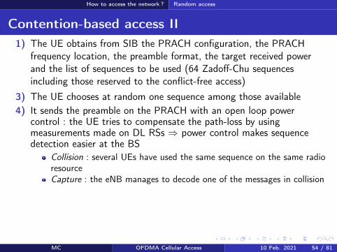
How to access the network Random access
Conflict-free access
The UE has a valid identity (C-RNTI)The eNB sends a (DCI) message on the PDCCH including theZadoff-Chu sequence to be usedCollisions are no more possible no collision resolution phase
MC OFDMA Cellular Access 10 Feb 2021 56 81
How to send and receive data
Section 7
How to send and receive data
MC OFDMA Cellular Access 10 Feb 2021 57 81
How to send and receive data Objectives
Objectives
Objectives Resource allocation tell UEs on which radio resources they will receivedata on the DL-SCH or on which resource they are allowed to transmiton the UL-SCHUE scheduling allocate RBs to UEs as a function of their demand andtheir radio conditionsError control ARQ and HARQ retransmissionsMeasurement feedbacks the UE tells the network the downlinkchannel radio quality or its preferred MIMO precoding matrix
MC OFDMA Cellular Access 10 Feb 2021 58 81
How to send and receive data Resource allocation
Resource allocation I
Location of resources in the sub-frame modulation and coding schemeare signaled in Downlink Control Information (DCI) messagestransmitted on the PDCCHs
Format Description0 Resource allocation on the PUSCH1 PDSCH resource allocation in TM1 TM2 TM71A PDSCH compact allocation and PRACH signature1B PDSCH resource allocation in TM61C PDSCH very compact allocation1D PDSCH compact allocation in TM52 PDSCH compact allocation in TM42A PDSCH compact allocation in TM33 Power control on PUCCHPUSCH (2 bits)3A Power control on PUCCHPUSCH (1 bit)
Table ndash DCI formats
MC OFDMA Cellular Access 10 Feb 2021 59 81
How to send and receive data Resource allocation
Resource allocation II
DCI 0 example A flag to differentiate 1 and 1AA flag for frequency hopping on the PUSCHResource block allocationModulation and coding scheme redundancy version for HARQHARQ new transmission indicatorA power control command for the ULCyclic shift to be applied to ZC sequence for DMRSA CQI request
Every DCI includes a CRC scrambled with a RNTI identityC-RNTI = to address a unique UEP-RNTI = paging messageSI-RNTI = SIBRA-RNTI = random access response
MC OFDMA Cellular Access 10 Feb 2021 60 81
How to send and receive data Scheduling
Scheduling I
Fast (every 1 ms) and adaptive (modulation and coding are adaptedto radio conditions) schedulingDL scheduling decisions are based on CQI feedbacks buffer statusand priorities between logical channelsUL the UE has to feedback its buffer status and radio resource needsby using either the PUCCH (scheduling request) or the UL-SCH (MACcontrol messages)
MC OFDMA Cellular Access 10 Feb 2021 61 81
How to send and receive data Scheduling
Scheduling IIAlgorithm LTE offers a new degree of freedom wrt HSPA thepossibility to schedule users on different radio blocks
Channel q
ualit
y
fPRB1 PRB2 PRB3 PRB4 PRB5
Channel UE1
Channel UE2
Channel UE3
Scheduling decisions UE2 UE3 UE1 UE3 UE2
Figure ndash Frequency Dependent Packet Scheduling (FDPS) in LTE
MC OFDMA Cellular Access 10 Feb 2021 62 81
How to send and receive data Scheduling
Scheduling III
f
t
Syste
m b
an
dw
idth
Sub-frame (1 ms)
f
t
Comb onesub-carrieris used outof two
(a) SRS transmission without frequency hopping
(b) SRS transmission with frequency hopping
Figure ndash Sounding Reference Signals (SRS) transmissions
The eNB estimates the channel quality on the UL thanks to SRS
SRS is transmitted on a bandwidth much larger than the one allocated to UEtransmissions
SRS from different UEs are multiplexed in time (different sub-frames and periods)frequency (different sets of RBs oddeven sub-carriers) or code (differentsequences)
MC OFDMA Cellular Access 10 Feb 2021 63 81
How to send and receive data Error control
ARQ and HARQ
Like in HSPA HARQ is in the MAC layer and ARQ in the RLCHARQ DL sequence number is signaled in the PDCCH ACKNACKare fed back in the PUSCH (with data) or in the PUCCHHARQ UL ACKNACK transmitted in the PHICHARQ Transparent Mode (TM) (no header no segmentation orconcatenation) Unacknowledged (UM) (header with sequencenumber) Acknowledged (AM) (ARQ)
MC OFDMA Cellular Access 10 Feb 2021 64 81
How to send and receive data Measurements
Measurements
Radio quality measurements CQI (Channel Quality Indicator) modulation (QPSK 16-QAM or64-QAM) and transport block maximum size that a UE can receivewith a BLERlt10 (Block Error Rate)RI (Rank Indicator) rank of the DL transmission = number ofindependent spatial layers that can be usedPMI (Precoding Matrix Indicator) UE preferred precoding matrix Wfor transmission modes with closed loop
Physical channels PUSCH for aperiodic feedbacks with data transmissionPUCCH for periodic feedbacks
MC OFDMA Cellular Access 10 Feb 2021 65 81
Terminals categories
Section 8
Terminals categories
MC OFDMA Cellular Access 10 Feb 2021 66 81
Terminals categories
Terminals categories
Caracteristics Cat 1 Cat 2 Cat 3 Cat 4 Cat 5Max number ofbits per TTI (DL) 10296 51024 102048 150752 299552
Max number ofbits per TTI (UL) 5160 25456 51024 51024 75376
Max data rate(DL) 10 Mbps 50 Mbps 100 Mbps 150 Mbps 300 Mbps
Max data rate(UL) 5 Mbps 25 Mbps 50 Mbps 50 Mbps 75 Mbps
64 QAM (UL) No No No No YesMIMO (DL) Option 2times 2 2times 2 2times 2 4times 4
Table ndash Terminal categories in LTE
For example the Semsong S5 is cat 4 the Semsong S6 is cat 6 (Release 1030050 Mbps) the Semsong S8 is cat1613 (Release 12 1050150 Mbps MIMO4x4 256-QAM 5CA) Semsong S10 is cat 2013 (2000 Mbps up to 8 MIMOlayers 256-QAM 7CA)
MC OFDMA Cellular Access 10 Feb 2021 67 81
Summary on channels
Section 9
Summary on channels
MC OFDMA Cellular Access 10 Feb 2021 68 81
Summary on channels
Physical channels DL I
PDSCH (Physical Downlink Shared Ch) physical shared channel for data
RS (Reference Signals) pilots required to estimate radio quality and toallow decoding on the DL
SS (Synchronization Signals) = PSS (Primary)+SSS (Secondary) for timeand frequency synchronization
PBCH (Physical Broadcast Ch) beacon MIB transmission
PCFICH (Physical Control Format Indicator Ch) tell the UEs how manyOFDM symbols are dedicated to the control part of the sub-frame (CFI)
PDCCH (Physical Downlink Control Ch) control informations (DCI resource allocation UE identity HARQ information MIMO etc)
PHICH (Physical Hybrid ARQ Indicator Ch) ACKNACK responses toHARQ transmissions from a UE (HI)
MC OFDMA Cellular Access 10 Feb 2021 69 81
Summary on channels
Physical channels UL I
In UL a UE is not able to multiplex different physical channels in the frequencydomain because of SC-FDMA limitation rArr time multiplexing is required
DMRS (Demodulation Reference Signal) used by the eNB to estimate thechannel and make radio quality measurements on the signal transmitted by theUE DMRS are sent in conjunction with PUCCH and PUSCH
SRS (Sounding Reference Signal) pilots used by the scheduler for the radioquality estimation on a bandwidth larger than the one allocated to the UE
PUCCH (Physical Uplink Control Ch) control informations UCI includingchannel quality (CQI) MIMO (closed loop) or HARQ (ACKNACK) informations
PUSCH (Physical Uplink Shared Ch) shared physical channels for data andcontrol
If a UE has data to transmit it uses the PUSCH for data and control Otherwiseit uses the PUCCH for the control
MC OFDMA Cellular Access 10 Feb 2021 70 81
Summary on channels
Transport channels DL
DL-SCH (DL Shared Ch) shared channel for data associated toPDSCHPCH (Paging Ch) broadcast of paging messages on the PDSCHBCH (Broadcast Ch) broadcast of system informations (SIBs) onthe PBCH and on the PDSCHDCI (DL Control Indicator) control information transmitted on thePDCCHs (transport format resource allocation HARQ and MIMOinformations power control commands)CFI (Control Format Indicator) number of OFDM symbols (12 or 3)used by PDCCHs at the beginning of every sub-frame CFI is sent onthe PCFICHHI (HARQ Indicator) ACK or NACK in response to a transmissionon the UL-SCH HI is transmitted on the PHICH
MC OFDMA Cellular Access 10 Feb 2021 71 81
Summary on channels
transport channels UL
RACH (Random Access Ch) random accessUL-SCH (UL Share Ch) shared channel for data and controlassociated to PUSCH User data and control informations aremultiplexed in time and frequency on the PUSCHUCI (UL Control Indicator) control information transmitted by thePUCCH (channel quality CQI closed loop MIMO informationsPMIRI ACKNACK of HARQ scheduling request)
MC OFDMA Cellular Access 10 Feb 2021 72 81
Summary on channels
Logical channels
Logical channel Type Description LinkBCCH Control System information DLPCCH Control Paging DLCCCH Control Control without RRC conn ULDLDCCH Controcircle Dedicated control ULDLDTCH Traffic user plane ULDL
Table ndash Logical channels in LTE DL and UL
BCCH (Broadcast COntrol Ch) system information associated to BCH for theMIB and DL-SCH for the SIBs
PCCH (Paging Control Ch) paging associated to PCH
CCCH (Common Control Ch) control messages between the network and UEswithout RRC connection associated to DL-SCH and UL-SCH
DCCH (Dedicated Control Ch) control messages between the network and UEswith RRC connection associated to DL-SCH and UL-SCH
MC OFDMA Cellular Access 10 Feb 2021 73 81
Conclusion
Section 10
Conclusion
MC OFDMA Cellular Access 10 Feb 2021 74 81
Conclusion
Conclusion
LTE A brand new standardA certain simplicity that is reminiscent of GSMSimilarities with 3G (channels HARQ MAC RLC etc)New features (MIMO MU-MIMO multi-carrier transmissions)
After LTE LTE-A R13 frozen in Mar 2016 (LTE Pro) R14 on goingR15 is called 5G New Radio (NR) and is the first 5G releasePeak rates of the order of 1GbpsCarrier aggregation discontinuous resource allocation on the ULMIMO 8times8 relays HetNets CoMP Self-Organized NetworksMBMS NB-IoT etc
MC OFDMA Cellular Access 10 Feb 2021 75 81
Conclusion
References I
3GPPTechnical Specification 36211 Physical channels and modulationDec 2009
3GPPTechnical Specification 36300 Evolved Universal Terrestrial RadioAccess (E-UTRA) and Evolved Universal Terrestrial Radio AccessNetwork (E-UTRAN) Overall description Apr 2010
3GPPTechnical Specification 36104 Base Station (BS) radio transmissionand reception Jun 2011
MC OFDMA Cellular Access 10 Feb 2021 76 81
Conclusion
References II
S M AlamoutiA simple transmit diversity technique for wireless communicationsIEEE J on Selected Areas in Communications 16(8) 1451ndash1458 Oct1998
MC OFDMA Cellular Access 10 Feb 2021 77 81
Conclusion
Acronyms I
AM ARQ Acknowledged ModeARQ Automatic Repeat on RequestBCCH Broadcast Control ChannelBCH Broadcast ChannelBLER Block Error RateBPSK Binary Phase Shift KeyingBS Base Station
CCCH Common Control ChannelCDMA Code Division Multiple AccessCFI Control Format Indocator
CoMP Coordinated Multi-PointCQI Channel Quality IndicatorCRC Cyclic Redundancy CodeD2D Device to DeviceDCCH Dedicated Control ChannelDCI Downlink Control InformationDL Downlink
DL-SCH Downlink Shared ChannelDMRS Demodulation Reference SignalDTCH Dedicated Traffic ChanneleNB eNode-BEPC Evolved Packet Core
E-UTRAN Evolved UTRANFDD Frequency Division DuplexFDPS Frequency Dependent Packet SchedulingFFT Fast Fourier TransformGSM Groupe Speacutecial MobileHARQ Hybrid Automatic Repeat on Request
MC OFDMA Cellular Access 10 Feb 2021 78 81
Conclusion
Acronyms IIHI HARQ Indicator
HSPA High Speed Packet AccessHSDPA High Speed Downlink Packet AccessHSPA High Speed Uplink Packet AccessICI Inter-Carrier InterferenceIFFT Inverse Fast Fourier TransformIMT International Mobile TelecommunicationsISI Inter-Symbol InterferenceLTE Long Term EvolutionMAC Medium Access ControlMBMS Multimedia Broadcast Multicast ServiceMIB Master Information BlockMIMO Multiple Input Multiple OutputMME Mobility Management Entity
MU-MIMO Multi-User MIMONAS Non Access StratumOFDM Orthogonal Frequency Division MultiplexOFDMA Orthogonal Frequency Division Multiple AccessPAPR Peak to Average Power RatioPBCH Physical Broadcast ChannelPCFICH Physical Control Format Indicator ChannelPCCH Paging Control ChannelPCH Paging ChannelPCI Physical Cell Identifier
PDCCH Physical Downlink Control ChannelPDCP Packet Data Convergence ProtocolPDSCH Physical Downlink Shared ChannelPDU Protocol Data Unit
MC OFDMA Cellular Access 10 Feb 2021 79 81
Conclusion
Acronyms IIIPHICH Physical Hybrid ARQ Indicator ChannelPMI Precoding Matrix IndicatorPSS Primary Synchronization Signal
PUCCH Physical Uplink Control ChannelPUSCH Physical Uplink Shared ChannelQAM Qadrature Amplitude ModulationQPSK Quadrature Phase Shift KeyingRACH Random Access ChannelRAR Random Access ResponseRB Resource BlockRE Resource ElementRI Rank IndicatorRLC Radio Link ControlRNC Radio Network ControllerRNTI Radio Network Temporary IdentifierROHC Robust Header CompressionRRC Radio Resource ControlRS Reference Signal
SC-FDMA Single Carrier Frequency Division Multiple AccessSDU Service Data UnitSFBC Space-Time Block CodeSGW Serving GatewaySIB System Information BlockSISO Single Input Single OutputSNR Signal to Noise RatioSRS Sounding Reference SignalSSS Secondary Synchronization SignalTA Timing Advance
MC OFDMA Cellular Access 10 Feb 2021 80 81
Conclusion
Acronyms IV
TDD Time Division DuplexTM Transmission ModeTM ARQ Transparent ModeTTI Transmission Time IntervalUCI Uplink Control InformationUE User EquipmentUM ARQ Unacknowledged Mode
UMTS Universal Mobile Telecommunications SystemUL Uplink
UL-SCH Uplink Shared ChannelUTRAN UMTS Terrestrial Radio Access NetworkWCDMA Wideband Code Division Multiple Access
MC OFDMA Cellular Access 10 Feb 2021 81 81

How to send and receive data
Section 7
How to send and receive data
MC OFDMA Cellular Access 10 Feb 2021 57 81
How to send and receive data Objectives
Objectives
Objectives Resource allocation tell UEs on which radio resources they will receivedata on the DL-SCH or on which resource they are allowed to transmiton the UL-SCHUE scheduling allocate RBs to UEs as a function of their demand andtheir radio conditionsError control ARQ and HARQ retransmissionsMeasurement feedbacks the UE tells the network the downlinkchannel radio quality or its preferred MIMO precoding matrix
MC OFDMA Cellular Access 10 Feb 2021 58 81
How to send and receive data Resource allocation
Resource allocation I
Location of resources in the sub-frame modulation and coding schemeare signaled in Downlink Control Information (DCI) messagestransmitted on the PDCCHs
Format Description0 Resource allocation on the PUSCH1 PDSCH resource allocation in TM1 TM2 TM71A PDSCH compact allocation and PRACH signature1B PDSCH resource allocation in TM61C PDSCH very compact allocation1D PDSCH compact allocation in TM52 PDSCH compact allocation in TM42A PDSCH compact allocation in TM33 Power control on PUCCHPUSCH (2 bits)3A Power control on PUCCHPUSCH (1 bit)
Table ndash DCI formats
MC OFDMA Cellular Access 10 Feb 2021 59 81
How to send and receive data Resource allocation
Resource allocation II
DCI 0 example A flag to differentiate 1 and 1AA flag for frequency hopping on the PUSCHResource block allocationModulation and coding scheme redundancy version for HARQHARQ new transmission indicatorA power control command for the ULCyclic shift to be applied to ZC sequence for DMRSA CQI request
Every DCI includes a CRC scrambled with a RNTI identityC-RNTI = to address a unique UEP-RNTI = paging messageSI-RNTI = SIBRA-RNTI = random access response
MC OFDMA Cellular Access 10 Feb 2021 60 81
How to send and receive data Scheduling
Scheduling I
Fast (every 1 ms) and adaptive (modulation and coding are adaptedto radio conditions) schedulingDL scheduling decisions are based on CQI feedbacks buffer statusand priorities between logical channelsUL the UE has to feedback its buffer status and radio resource needsby using either the PUCCH (scheduling request) or the UL-SCH (MACcontrol messages)
MC OFDMA Cellular Access 10 Feb 2021 61 81
How to send and receive data Scheduling
Scheduling IIAlgorithm LTE offers a new degree of freedom wrt HSPA thepossibility to schedule users on different radio blocks
Channel q
ualit
y
fPRB1 PRB2 PRB3 PRB4 PRB5
Channel UE1
Channel UE2
Channel UE3
Scheduling decisions UE2 UE3 UE1 UE3 UE2
Figure ndash Frequency Dependent Packet Scheduling (FDPS) in LTE
MC OFDMA Cellular Access 10 Feb 2021 62 81
How to send and receive data Scheduling
Scheduling III
f
t
Syste
m b
an
dw
idth
Sub-frame (1 ms)
f
t
Comb onesub-carrieris used outof two
(a) SRS transmission without frequency hopping
(b) SRS transmission with frequency hopping
Figure ndash Sounding Reference Signals (SRS) transmissions
The eNB estimates the channel quality on the UL thanks to SRS
SRS is transmitted on a bandwidth much larger than the one allocated to UEtransmissions
SRS from different UEs are multiplexed in time (different sub-frames and periods)frequency (different sets of RBs oddeven sub-carriers) or code (differentsequences)
MC OFDMA Cellular Access 10 Feb 2021 63 81
How to send and receive data Error control
ARQ and HARQ
Like in HSPA HARQ is in the MAC layer and ARQ in the RLCHARQ DL sequence number is signaled in the PDCCH ACKNACKare fed back in the PUSCH (with data) or in the PUCCHHARQ UL ACKNACK transmitted in the PHICHARQ Transparent Mode (TM) (no header no segmentation orconcatenation) Unacknowledged (UM) (header with sequencenumber) Acknowledged (AM) (ARQ)
MC OFDMA Cellular Access 10 Feb 2021 64 81
How to send and receive data Measurements
Measurements
Radio quality measurements CQI (Channel Quality Indicator) modulation (QPSK 16-QAM or64-QAM) and transport block maximum size that a UE can receivewith a BLERlt10 (Block Error Rate)RI (Rank Indicator) rank of the DL transmission = number ofindependent spatial layers that can be usedPMI (Precoding Matrix Indicator) UE preferred precoding matrix Wfor transmission modes with closed loop
Physical channels PUSCH for aperiodic feedbacks with data transmissionPUCCH for periodic feedbacks
MC OFDMA Cellular Access 10 Feb 2021 65 81
Terminals categories
Section 8
Terminals categories
MC OFDMA Cellular Access 10 Feb 2021 66 81
Terminals categories
Terminals categories
Caracteristics Cat 1 Cat 2 Cat 3 Cat 4 Cat 5Max number ofbits per TTI (DL) 10296 51024 102048 150752 299552
Max number ofbits per TTI (UL) 5160 25456 51024 51024 75376
Max data rate(DL) 10 Mbps 50 Mbps 100 Mbps 150 Mbps 300 Mbps
Max data rate(UL) 5 Mbps 25 Mbps 50 Mbps 50 Mbps 75 Mbps
64 QAM (UL) No No No No YesMIMO (DL) Option 2times 2 2times 2 2times 2 4times 4
Table ndash Terminal categories in LTE
For example the Semsong S5 is cat 4 the Semsong S6 is cat 6 (Release 1030050 Mbps) the Semsong S8 is cat1613 (Release 12 1050150 Mbps MIMO4x4 256-QAM 5CA) Semsong S10 is cat 2013 (2000 Mbps up to 8 MIMOlayers 256-QAM 7CA)
MC OFDMA Cellular Access 10 Feb 2021 67 81
Summary on channels
Section 9
Summary on channels
MC OFDMA Cellular Access 10 Feb 2021 68 81
Summary on channels
Physical channels DL I
PDSCH (Physical Downlink Shared Ch) physical shared channel for data
RS (Reference Signals) pilots required to estimate radio quality and toallow decoding on the DL
SS (Synchronization Signals) = PSS (Primary)+SSS (Secondary) for timeand frequency synchronization
PBCH (Physical Broadcast Ch) beacon MIB transmission
PCFICH (Physical Control Format Indicator Ch) tell the UEs how manyOFDM symbols are dedicated to the control part of the sub-frame (CFI)
PDCCH (Physical Downlink Control Ch) control informations (DCI resource allocation UE identity HARQ information MIMO etc)
PHICH (Physical Hybrid ARQ Indicator Ch) ACKNACK responses toHARQ transmissions from a UE (HI)
MC OFDMA Cellular Access 10 Feb 2021 69 81
Summary on channels
Physical channels UL I
In UL a UE is not able to multiplex different physical channels in the frequencydomain because of SC-FDMA limitation rArr time multiplexing is required
DMRS (Demodulation Reference Signal) used by the eNB to estimate thechannel and make radio quality measurements on the signal transmitted by theUE DMRS are sent in conjunction with PUCCH and PUSCH
SRS (Sounding Reference Signal) pilots used by the scheduler for the radioquality estimation on a bandwidth larger than the one allocated to the UE
PUCCH (Physical Uplink Control Ch) control informations UCI includingchannel quality (CQI) MIMO (closed loop) or HARQ (ACKNACK) informations
PUSCH (Physical Uplink Shared Ch) shared physical channels for data andcontrol
If a UE has data to transmit it uses the PUSCH for data and control Otherwiseit uses the PUCCH for the control
MC OFDMA Cellular Access 10 Feb 2021 70 81
Summary on channels
Transport channels DL
DL-SCH (DL Shared Ch) shared channel for data associated toPDSCHPCH (Paging Ch) broadcast of paging messages on the PDSCHBCH (Broadcast Ch) broadcast of system informations (SIBs) onthe PBCH and on the PDSCHDCI (DL Control Indicator) control information transmitted on thePDCCHs (transport format resource allocation HARQ and MIMOinformations power control commands)CFI (Control Format Indicator) number of OFDM symbols (12 or 3)used by PDCCHs at the beginning of every sub-frame CFI is sent onthe PCFICHHI (HARQ Indicator) ACK or NACK in response to a transmissionon the UL-SCH HI is transmitted on the PHICH
MC OFDMA Cellular Access 10 Feb 2021 71 81
Summary on channels
transport channels UL
RACH (Random Access Ch) random accessUL-SCH (UL Share Ch) shared channel for data and controlassociated to PUSCH User data and control informations aremultiplexed in time and frequency on the PUSCHUCI (UL Control Indicator) control information transmitted by thePUCCH (channel quality CQI closed loop MIMO informationsPMIRI ACKNACK of HARQ scheduling request)
MC OFDMA Cellular Access 10 Feb 2021 72 81
Summary on channels
Logical channels
Logical channel Type Description LinkBCCH Control System information DLPCCH Control Paging DLCCCH Control Control without RRC conn ULDLDCCH Controcircle Dedicated control ULDLDTCH Traffic user plane ULDL
Table ndash Logical channels in LTE DL and UL
BCCH (Broadcast COntrol Ch) system information associated to BCH for theMIB and DL-SCH for the SIBs
PCCH (Paging Control Ch) paging associated to PCH
CCCH (Common Control Ch) control messages between the network and UEswithout RRC connection associated to DL-SCH and UL-SCH
DCCH (Dedicated Control Ch) control messages between the network and UEswith RRC connection associated to DL-SCH and UL-SCH
MC OFDMA Cellular Access 10 Feb 2021 73 81
Conclusion
Section 10
Conclusion
MC OFDMA Cellular Access 10 Feb 2021 74 81
Conclusion
Conclusion
LTE A brand new standardA certain simplicity that is reminiscent of GSMSimilarities with 3G (channels HARQ MAC RLC etc)New features (MIMO MU-MIMO multi-carrier transmissions)
After LTE LTE-A R13 frozen in Mar 2016 (LTE Pro) R14 on goingR15 is called 5G New Radio (NR) and is the first 5G releasePeak rates of the order of 1GbpsCarrier aggregation discontinuous resource allocation on the ULMIMO 8times8 relays HetNets CoMP Self-Organized NetworksMBMS NB-IoT etc
MC OFDMA Cellular Access 10 Feb 2021 75 81
Conclusion
References I
3GPPTechnical Specification 36211 Physical channels and modulationDec 2009
3GPPTechnical Specification 36300 Evolved Universal Terrestrial RadioAccess (E-UTRA) and Evolved Universal Terrestrial Radio AccessNetwork (E-UTRAN) Overall description Apr 2010
3GPPTechnical Specification 36104 Base Station (BS) radio transmissionand reception Jun 2011
MC OFDMA Cellular Access 10 Feb 2021 76 81
Conclusion
References II
S M AlamoutiA simple transmit diversity technique for wireless communicationsIEEE J on Selected Areas in Communications 16(8) 1451ndash1458 Oct1998
MC OFDMA Cellular Access 10 Feb 2021 77 81
Conclusion
Acronyms I
AM ARQ Acknowledged ModeARQ Automatic Repeat on RequestBCCH Broadcast Control ChannelBCH Broadcast ChannelBLER Block Error RateBPSK Binary Phase Shift KeyingBS Base Station
CCCH Common Control ChannelCDMA Code Division Multiple AccessCFI Control Format Indocator
CoMP Coordinated Multi-PointCQI Channel Quality IndicatorCRC Cyclic Redundancy CodeD2D Device to DeviceDCCH Dedicated Control ChannelDCI Downlink Control InformationDL Downlink
DL-SCH Downlink Shared ChannelDMRS Demodulation Reference SignalDTCH Dedicated Traffic ChanneleNB eNode-BEPC Evolved Packet Core
E-UTRAN Evolved UTRANFDD Frequency Division DuplexFDPS Frequency Dependent Packet SchedulingFFT Fast Fourier TransformGSM Groupe Speacutecial MobileHARQ Hybrid Automatic Repeat on Request
MC OFDMA Cellular Access 10 Feb 2021 78 81
Conclusion
Acronyms IIHI HARQ Indicator
HSPA High Speed Packet AccessHSDPA High Speed Downlink Packet AccessHSPA High Speed Uplink Packet AccessICI Inter-Carrier InterferenceIFFT Inverse Fast Fourier TransformIMT International Mobile TelecommunicationsISI Inter-Symbol InterferenceLTE Long Term EvolutionMAC Medium Access ControlMBMS Multimedia Broadcast Multicast ServiceMIB Master Information BlockMIMO Multiple Input Multiple OutputMME Mobility Management Entity
MU-MIMO Multi-User MIMONAS Non Access StratumOFDM Orthogonal Frequency Division MultiplexOFDMA Orthogonal Frequency Division Multiple AccessPAPR Peak to Average Power RatioPBCH Physical Broadcast ChannelPCFICH Physical Control Format Indicator ChannelPCCH Paging Control ChannelPCH Paging ChannelPCI Physical Cell Identifier
PDCCH Physical Downlink Control ChannelPDCP Packet Data Convergence ProtocolPDSCH Physical Downlink Shared ChannelPDU Protocol Data Unit
MC OFDMA Cellular Access 10 Feb 2021 79 81
Conclusion
Acronyms IIIPHICH Physical Hybrid ARQ Indicator ChannelPMI Precoding Matrix IndicatorPSS Primary Synchronization Signal
PUCCH Physical Uplink Control ChannelPUSCH Physical Uplink Shared ChannelQAM Qadrature Amplitude ModulationQPSK Quadrature Phase Shift KeyingRACH Random Access ChannelRAR Random Access ResponseRB Resource BlockRE Resource ElementRI Rank IndicatorRLC Radio Link ControlRNC Radio Network ControllerRNTI Radio Network Temporary IdentifierROHC Robust Header CompressionRRC Radio Resource ControlRS Reference Signal
SC-FDMA Single Carrier Frequency Division Multiple AccessSDU Service Data UnitSFBC Space-Time Block CodeSGW Serving GatewaySIB System Information BlockSISO Single Input Single OutputSNR Signal to Noise RatioSRS Sounding Reference SignalSSS Secondary Synchronization SignalTA Timing Advance
MC OFDMA Cellular Access 10 Feb 2021 80 81
Conclusion
Acronyms IV
TDD Time Division DuplexTM Transmission ModeTM ARQ Transparent ModeTTI Transmission Time IntervalUCI Uplink Control InformationUE User EquipmentUM ARQ Unacknowledged Mode
UMTS Universal Mobile Telecommunications SystemUL Uplink
UL-SCH Uplink Shared ChannelUTRAN UMTS Terrestrial Radio Access NetworkWCDMA Wideband Code Division Multiple Access
MC OFDMA Cellular Access 10 Feb 2021 81 81

How to send and receive data Resource allocation
Resource allocation II
DCI 0 example A flag to differentiate 1 and 1AA flag for frequency hopping on the PUSCHResource block allocationModulation and coding scheme redundancy version for HARQHARQ new transmission indicatorA power control command for the ULCyclic shift to be applied to ZC sequence for DMRSA CQI request
Every DCI includes a CRC scrambled with a RNTI identityC-RNTI = to address a unique UEP-RNTI = paging messageSI-RNTI = SIBRA-RNTI = random access response
MC OFDMA Cellular Access 10 Feb 2021 60 81
How to send and receive data Scheduling
Scheduling I
Fast (every 1 ms) and adaptive (modulation and coding are adaptedto radio conditions) schedulingDL scheduling decisions are based on CQI feedbacks buffer statusand priorities between logical channelsUL the UE has to feedback its buffer status and radio resource needsby using either the PUCCH (scheduling request) or the UL-SCH (MACcontrol messages)
MC OFDMA Cellular Access 10 Feb 2021 61 81
How to send and receive data Scheduling
Scheduling IIAlgorithm LTE offers a new degree of freedom wrt HSPA thepossibility to schedule users on different radio blocks
Channel q
ualit
y
fPRB1 PRB2 PRB3 PRB4 PRB5
Channel UE1
Channel UE2
Channel UE3
Scheduling decisions UE2 UE3 UE1 UE3 UE2
Figure ndash Frequency Dependent Packet Scheduling (FDPS) in LTE
MC OFDMA Cellular Access 10 Feb 2021 62 81
How to send and receive data Scheduling
Scheduling III
f
t
Syste
m b
an
dw
idth
Sub-frame (1 ms)
f
t
Comb onesub-carrieris used outof two
(a) SRS transmission without frequency hopping
(b) SRS transmission with frequency hopping
Figure ndash Sounding Reference Signals (SRS) transmissions
The eNB estimates the channel quality on the UL thanks to SRS
SRS is transmitted on a bandwidth much larger than the one allocated to UEtransmissions
SRS from different UEs are multiplexed in time (different sub-frames and periods)frequency (different sets of RBs oddeven sub-carriers) or code (differentsequences)
MC OFDMA Cellular Access 10 Feb 2021 63 81
How to send and receive data Error control
ARQ and HARQ
Like in HSPA HARQ is in the MAC layer and ARQ in the RLCHARQ DL sequence number is signaled in the PDCCH ACKNACKare fed back in the PUSCH (with data) or in the PUCCHHARQ UL ACKNACK transmitted in the PHICHARQ Transparent Mode (TM) (no header no segmentation orconcatenation) Unacknowledged (UM) (header with sequencenumber) Acknowledged (AM) (ARQ)
MC OFDMA Cellular Access 10 Feb 2021 64 81
How to send and receive data Measurements
Measurements
Radio quality measurements CQI (Channel Quality Indicator) modulation (QPSK 16-QAM or64-QAM) and transport block maximum size that a UE can receivewith a BLERlt10 (Block Error Rate)RI (Rank Indicator) rank of the DL transmission = number ofindependent spatial layers that can be usedPMI (Precoding Matrix Indicator) UE preferred precoding matrix Wfor transmission modes with closed loop
Physical channels PUSCH for aperiodic feedbacks with data transmissionPUCCH for periodic feedbacks
MC OFDMA Cellular Access 10 Feb 2021 65 81
Terminals categories
Section 8
Terminals categories
MC OFDMA Cellular Access 10 Feb 2021 66 81
Terminals categories
Terminals categories
Caracteristics Cat 1 Cat 2 Cat 3 Cat 4 Cat 5Max number ofbits per TTI (DL) 10296 51024 102048 150752 299552
Max number ofbits per TTI (UL) 5160 25456 51024 51024 75376
Max data rate(DL) 10 Mbps 50 Mbps 100 Mbps 150 Mbps 300 Mbps
Max data rate(UL) 5 Mbps 25 Mbps 50 Mbps 50 Mbps 75 Mbps
64 QAM (UL) No No No No YesMIMO (DL) Option 2times 2 2times 2 2times 2 4times 4
Table ndash Terminal categories in LTE
For example the Semsong S5 is cat 4 the Semsong S6 is cat 6 (Release 1030050 Mbps) the Semsong S8 is cat1613 (Release 12 1050150 Mbps MIMO4x4 256-QAM 5CA) Semsong S10 is cat 2013 (2000 Mbps up to 8 MIMOlayers 256-QAM 7CA)
MC OFDMA Cellular Access 10 Feb 2021 67 81
Summary on channels
Section 9
Summary on channels
MC OFDMA Cellular Access 10 Feb 2021 68 81
Summary on channels
Physical channels DL I
PDSCH (Physical Downlink Shared Ch) physical shared channel for data
RS (Reference Signals) pilots required to estimate radio quality and toallow decoding on the DL
SS (Synchronization Signals) = PSS (Primary)+SSS (Secondary) for timeand frequency synchronization
PBCH (Physical Broadcast Ch) beacon MIB transmission
PCFICH (Physical Control Format Indicator Ch) tell the UEs how manyOFDM symbols are dedicated to the control part of the sub-frame (CFI)
PDCCH (Physical Downlink Control Ch) control informations (DCI resource allocation UE identity HARQ information MIMO etc)
PHICH (Physical Hybrid ARQ Indicator Ch) ACKNACK responses toHARQ transmissions from a UE (HI)
MC OFDMA Cellular Access 10 Feb 2021 69 81
Summary on channels
Physical channels UL I
In UL a UE is not able to multiplex different physical channels in the frequencydomain because of SC-FDMA limitation rArr time multiplexing is required
DMRS (Demodulation Reference Signal) used by the eNB to estimate thechannel and make radio quality measurements on the signal transmitted by theUE DMRS are sent in conjunction with PUCCH and PUSCH
SRS (Sounding Reference Signal) pilots used by the scheduler for the radioquality estimation on a bandwidth larger than the one allocated to the UE
PUCCH (Physical Uplink Control Ch) control informations UCI includingchannel quality (CQI) MIMO (closed loop) or HARQ (ACKNACK) informations
PUSCH (Physical Uplink Shared Ch) shared physical channels for data andcontrol
If a UE has data to transmit it uses the PUSCH for data and control Otherwiseit uses the PUCCH for the control
MC OFDMA Cellular Access 10 Feb 2021 70 81
Summary on channels
Transport channels DL
DL-SCH (DL Shared Ch) shared channel for data associated toPDSCHPCH (Paging Ch) broadcast of paging messages on the PDSCHBCH (Broadcast Ch) broadcast of system informations (SIBs) onthe PBCH and on the PDSCHDCI (DL Control Indicator) control information transmitted on thePDCCHs (transport format resource allocation HARQ and MIMOinformations power control commands)CFI (Control Format Indicator) number of OFDM symbols (12 or 3)used by PDCCHs at the beginning of every sub-frame CFI is sent onthe PCFICHHI (HARQ Indicator) ACK or NACK in response to a transmissionon the UL-SCH HI is transmitted on the PHICH
MC OFDMA Cellular Access 10 Feb 2021 71 81
Summary on channels
transport channels UL
RACH (Random Access Ch) random accessUL-SCH (UL Share Ch) shared channel for data and controlassociated to PUSCH User data and control informations aremultiplexed in time and frequency on the PUSCHUCI (UL Control Indicator) control information transmitted by thePUCCH (channel quality CQI closed loop MIMO informationsPMIRI ACKNACK of HARQ scheduling request)
MC OFDMA Cellular Access 10 Feb 2021 72 81
Summary on channels
Logical channels
Logical channel Type Description LinkBCCH Control System information DLPCCH Control Paging DLCCCH Control Control without RRC conn ULDLDCCH Controcircle Dedicated control ULDLDTCH Traffic user plane ULDL
Table ndash Logical channels in LTE DL and UL
BCCH (Broadcast COntrol Ch) system information associated to BCH for theMIB and DL-SCH for the SIBs
PCCH (Paging Control Ch) paging associated to PCH
CCCH (Common Control Ch) control messages between the network and UEswithout RRC connection associated to DL-SCH and UL-SCH
DCCH (Dedicated Control Ch) control messages between the network and UEswith RRC connection associated to DL-SCH and UL-SCH
MC OFDMA Cellular Access 10 Feb 2021 73 81
Conclusion
Section 10
Conclusion
MC OFDMA Cellular Access 10 Feb 2021 74 81
Conclusion
Conclusion
LTE A brand new standardA certain simplicity that is reminiscent of GSMSimilarities with 3G (channels HARQ MAC RLC etc)New features (MIMO MU-MIMO multi-carrier transmissions)
After LTE LTE-A R13 frozen in Mar 2016 (LTE Pro) R14 on goingR15 is called 5G New Radio (NR) and is the first 5G releasePeak rates of the order of 1GbpsCarrier aggregation discontinuous resource allocation on the ULMIMO 8times8 relays HetNets CoMP Self-Organized NetworksMBMS NB-IoT etc
MC OFDMA Cellular Access 10 Feb 2021 75 81
Conclusion
References I
3GPPTechnical Specification 36211 Physical channels and modulationDec 2009
3GPPTechnical Specification 36300 Evolved Universal Terrestrial RadioAccess (E-UTRA) and Evolved Universal Terrestrial Radio AccessNetwork (E-UTRAN) Overall description Apr 2010
3GPPTechnical Specification 36104 Base Station (BS) radio transmissionand reception Jun 2011
MC OFDMA Cellular Access 10 Feb 2021 76 81
Conclusion
References II
S M AlamoutiA simple transmit diversity technique for wireless communicationsIEEE J on Selected Areas in Communications 16(8) 1451ndash1458 Oct1998
MC OFDMA Cellular Access 10 Feb 2021 77 81
Conclusion
Acronyms I
AM ARQ Acknowledged ModeARQ Automatic Repeat on RequestBCCH Broadcast Control ChannelBCH Broadcast ChannelBLER Block Error RateBPSK Binary Phase Shift KeyingBS Base Station
CCCH Common Control ChannelCDMA Code Division Multiple AccessCFI Control Format Indocator
CoMP Coordinated Multi-PointCQI Channel Quality IndicatorCRC Cyclic Redundancy CodeD2D Device to DeviceDCCH Dedicated Control ChannelDCI Downlink Control InformationDL Downlink
DL-SCH Downlink Shared ChannelDMRS Demodulation Reference SignalDTCH Dedicated Traffic ChanneleNB eNode-BEPC Evolved Packet Core
E-UTRAN Evolved UTRANFDD Frequency Division DuplexFDPS Frequency Dependent Packet SchedulingFFT Fast Fourier TransformGSM Groupe Speacutecial MobileHARQ Hybrid Automatic Repeat on Request
MC OFDMA Cellular Access 10 Feb 2021 78 81
Conclusion
Acronyms IIHI HARQ Indicator
HSPA High Speed Packet AccessHSDPA High Speed Downlink Packet AccessHSPA High Speed Uplink Packet AccessICI Inter-Carrier InterferenceIFFT Inverse Fast Fourier TransformIMT International Mobile TelecommunicationsISI Inter-Symbol InterferenceLTE Long Term EvolutionMAC Medium Access ControlMBMS Multimedia Broadcast Multicast ServiceMIB Master Information BlockMIMO Multiple Input Multiple OutputMME Mobility Management Entity
MU-MIMO Multi-User MIMONAS Non Access StratumOFDM Orthogonal Frequency Division MultiplexOFDMA Orthogonal Frequency Division Multiple AccessPAPR Peak to Average Power RatioPBCH Physical Broadcast ChannelPCFICH Physical Control Format Indicator ChannelPCCH Paging Control ChannelPCH Paging ChannelPCI Physical Cell Identifier
PDCCH Physical Downlink Control ChannelPDCP Packet Data Convergence ProtocolPDSCH Physical Downlink Shared ChannelPDU Protocol Data Unit
MC OFDMA Cellular Access 10 Feb 2021 79 81
Conclusion
Acronyms IIIPHICH Physical Hybrid ARQ Indicator ChannelPMI Precoding Matrix IndicatorPSS Primary Synchronization Signal
PUCCH Physical Uplink Control ChannelPUSCH Physical Uplink Shared ChannelQAM Qadrature Amplitude ModulationQPSK Quadrature Phase Shift KeyingRACH Random Access ChannelRAR Random Access ResponseRB Resource BlockRE Resource ElementRI Rank IndicatorRLC Radio Link ControlRNC Radio Network ControllerRNTI Radio Network Temporary IdentifierROHC Robust Header CompressionRRC Radio Resource ControlRS Reference Signal
SC-FDMA Single Carrier Frequency Division Multiple AccessSDU Service Data UnitSFBC Space-Time Block CodeSGW Serving GatewaySIB System Information BlockSISO Single Input Single OutputSNR Signal to Noise RatioSRS Sounding Reference SignalSSS Secondary Synchronization SignalTA Timing Advance
MC OFDMA Cellular Access 10 Feb 2021 80 81
Conclusion
Acronyms IV
TDD Time Division DuplexTM Transmission ModeTM ARQ Transparent ModeTTI Transmission Time IntervalUCI Uplink Control InformationUE User EquipmentUM ARQ Unacknowledged Mode
UMTS Universal Mobile Telecommunications SystemUL Uplink
UL-SCH Uplink Shared ChannelUTRAN UMTS Terrestrial Radio Access NetworkWCDMA Wideband Code Division Multiple Access
MC OFDMA Cellular Access 10 Feb 2021 81 81

How to send and receive data Scheduling
Scheduling III
f
t
Syste
m b
an
dw
idth
Sub-frame (1 ms)
f
t
Comb onesub-carrieris used outof two
(a) SRS transmission without frequency hopping
(b) SRS transmission with frequency hopping
Figure ndash Sounding Reference Signals (SRS) transmissions
The eNB estimates the channel quality on the UL thanks to SRS
SRS is transmitted on a bandwidth much larger than the one allocated to UEtransmissions
SRS from different UEs are multiplexed in time (different sub-frames and periods)frequency (different sets of RBs oddeven sub-carriers) or code (differentsequences)
MC OFDMA Cellular Access 10 Feb 2021 63 81
How to send and receive data Error control
ARQ and HARQ
Like in HSPA HARQ is in the MAC layer and ARQ in the RLCHARQ DL sequence number is signaled in the PDCCH ACKNACKare fed back in the PUSCH (with data) or in the PUCCHHARQ UL ACKNACK transmitted in the PHICHARQ Transparent Mode (TM) (no header no segmentation orconcatenation) Unacknowledged (UM) (header with sequencenumber) Acknowledged (AM) (ARQ)
MC OFDMA Cellular Access 10 Feb 2021 64 81
How to send and receive data Measurements
Measurements
Radio quality measurements CQI (Channel Quality Indicator) modulation (QPSK 16-QAM or64-QAM) and transport block maximum size that a UE can receivewith a BLERlt10 (Block Error Rate)RI (Rank Indicator) rank of the DL transmission = number ofindependent spatial layers that can be usedPMI (Precoding Matrix Indicator) UE preferred precoding matrix Wfor transmission modes with closed loop
Physical channels PUSCH for aperiodic feedbacks with data transmissionPUCCH for periodic feedbacks
MC OFDMA Cellular Access 10 Feb 2021 65 81
Terminals categories
Section 8
Terminals categories
MC OFDMA Cellular Access 10 Feb 2021 66 81
Terminals categories
Terminals categories
Caracteristics Cat 1 Cat 2 Cat 3 Cat 4 Cat 5Max number ofbits per TTI (DL) 10296 51024 102048 150752 299552
Max number ofbits per TTI (UL) 5160 25456 51024 51024 75376
Max data rate(DL) 10 Mbps 50 Mbps 100 Mbps 150 Mbps 300 Mbps
Max data rate(UL) 5 Mbps 25 Mbps 50 Mbps 50 Mbps 75 Mbps
64 QAM (UL) No No No No YesMIMO (DL) Option 2times 2 2times 2 2times 2 4times 4
Table ndash Terminal categories in LTE
For example the Semsong S5 is cat 4 the Semsong S6 is cat 6 (Release 1030050 Mbps) the Semsong S8 is cat1613 (Release 12 1050150 Mbps MIMO4x4 256-QAM 5CA) Semsong S10 is cat 2013 (2000 Mbps up to 8 MIMOlayers 256-QAM 7CA)
MC OFDMA Cellular Access 10 Feb 2021 67 81
Summary on channels
Section 9
Summary on channels
MC OFDMA Cellular Access 10 Feb 2021 68 81
Summary on channels
Physical channels DL I
PDSCH (Physical Downlink Shared Ch) physical shared channel for data
RS (Reference Signals) pilots required to estimate radio quality and toallow decoding on the DL
SS (Synchronization Signals) = PSS (Primary)+SSS (Secondary) for timeand frequency synchronization
PBCH (Physical Broadcast Ch) beacon MIB transmission
PCFICH (Physical Control Format Indicator Ch) tell the UEs how manyOFDM symbols are dedicated to the control part of the sub-frame (CFI)
PDCCH (Physical Downlink Control Ch) control informations (DCI resource allocation UE identity HARQ information MIMO etc)
PHICH (Physical Hybrid ARQ Indicator Ch) ACKNACK responses toHARQ transmissions from a UE (HI)
MC OFDMA Cellular Access 10 Feb 2021 69 81
Summary on channels
Physical channels UL I
In UL a UE is not able to multiplex different physical channels in the frequencydomain because of SC-FDMA limitation rArr time multiplexing is required
DMRS (Demodulation Reference Signal) used by the eNB to estimate thechannel and make radio quality measurements on the signal transmitted by theUE DMRS are sent in conjunction with PUCCH and PUSCH
SRS (Sounding Reference Signal) pilots used by the scheduler for the radioquality estimation on a bandwidth larger than the one allocated to the UE
PUCCH (Physical Uplink Control Ch) control informations UCI includingchannel quality (CQI) MIMO (closed loop) or HARQ (ACKNACK) informations
PUSCH (Physical Uplink Shared Ch) shared physical channels for data andcontrol
If a UE has data to transmit it uses the PUSCH for data and control Otherwiseit uses the PUCCH for the control
MC OFDMA Cellular Access 10 Feb 2021 70 81
Summary on channels
Transport channels DL
DL-SCH (DL Shared Ch) shared channel for data associated toPDSCHPCH (Paging Ch) broadcast of paging messages on the PDSCHBCH (Broadcast Ch) broadcast of system informations (SIBs) onthe PBCH and on the PDSCHDCI (DL Control Indicator) control information transmitted on thePDCCHs (transport format resource allocation HARQ and MIMOinformations power control commands)CFI (Control Format Indicator) number of OFDM symbols (12 or 3)used by PDCCHs at the beginning of every sub-frame CFI is sent onthe PCFICHHI (HARQ Indicator) ACK or NACK in response to a transmissionon the UL-SCH HI is transmitted on the PHICH
MC OFDMA Cellular Access 10 Feb 2021 71 81
Summary on channels
transport channels UL
RACH (Random Access Ch) random accessUL-SCH (UL Share Ch) shared channel for data and controlassociated to PUSCH User data and control informations aremultiplexed in time and frequency on the PUSCHUCI (UL Control Indicator) control information transmitted by thePUCCH (channel quality CQI closed loop MIMO informationsPMIRI ACKNACK of HARQ scheduling request)
MC OFDMA Cellular Access 10 Feb 2021 72 81
Summary on channels
Logical channels
Logical channel Type Description LinkBCCH Control System information DLPCCH Control Paging DLCCCH Control Control without RRC conn ULDLDCCH Controcircle Dedicated control ULDLDTCH Traffic user plane ULDL
Table ndash Logical channels in LTE DL and UL
BCCH (Broadcast COntrol Ch) system information associated to BCH for theMIB and DL-SCH for the SIBs
PCCH (Paging Control Ch) paging associated to PCH
CCCH (Common Control Ch) control messages between the network and UEswithout RRC connection associated to DL-SCH and UL-SCH
DCCH (Dedicated Control Ch) control messages between the network and UEswith RRC connection associated to DL-SCH and UL-SCH
MC OFDMA Cellular Access 10 Feb 2021 73 81
Conclusion
Section 10
Conclusion
MC OFDMA Cellular Access 10 Feb 2021 74 81
Conclusion
Conclusion
LTE A brand new standardA certain simplicity that is reminiscent of GSMSimilarities with 3G (channels HARQ MAC RLC etc)New features (MIMO MU-MIMO multi-carrier transmissions)
After LTE LTE-A R13 frozen in Mar 2016 (LTE Pro) R14 on goingR15 is called 5G New Radio (NR) and is the first 5G releasePeak rates of the order of 1GbpsCarrier aggregation discontinuous resource allocation on the ULMIMO 8times8 relays HetNets CoMP Self-Organized NetworksMBMS NB-IoT etc
MC OFDMA Cellular Access 10 Feb 2021 75 81
Conclusion
References I
3GPPTechnical Specification 36211 Physical channels and modulationDec 2009
3GPPTechnical Specification 36300 Evolved Universal Terrestrial RadioAccess (E-UTRA) and Evolved Universal Terrestrial Radio AccessNetwork (E-UTRAN) Overall description Apr 2010
3GPPTechnical Specification 36104 Base Station (BS) radio transmissionand reception Jun 2011
MC OFDMA Cellular Access 10 Feb 2021 76 81
Conclusion
References II
S M AlamoutiA simple transmit diversity technique for wireless communicationsIEEE J on Selected Areas in Communications 16(8) 1451ndash1458 Oct1998
MC OFDMA Cellular Access 10 Feb 2021 77 81
Conclusion
Acronyms I
AM ARQ Acknowledged ModeARQ Automatic Repeat on RequestBCCH Broadcast Control ChannelBCH Broadcast ChannelBLER Block Error RateBPSK Binary Phase Shift KeyingBS Base Station
CCCH Common Control ChannelCDMA Code Division Multiple AccessCFI Control Format Indocator
CoMP Coordinated Multi-PointCQI Channel Quality IndicatorCRC Cyclic Redundancy CodeD2D Device to DeviceDCCH Dedicated Control ChannelDCI Downlink Control InformationDL Downlink
DL-SCH Downlink Shared ChannelDMRS Demodulation Reference SignalDTCH Dedicated Traffic ChanneleNB eNode-BEPC Evolved Packet Core
E-UTRAN Evolved UTRANFDD Frequency Division DuplexFDPS Frequency Dependent Packet SchedulingFFT Fast Fourier TransformGSM Groupe Speacutecial MobileHARQ Hybrid Automatic Repeat on Request
MC OFDMA Cellular Access 10 Feb 2021 78 81
Conclusion
Acronyms IIHI HARQ Indicator
HSPA High Speed Packet AccessHSDPA High Speed Downlink Packet AccessHSPA High Speed Uplink Packet AccessICI Inter-Carrier InterferenceIFFT Inverse Fast Fourier TransformIMT International Mobile TelecommunicationsISI Inter-Symbol InterferenceLTE Long Term EvolutionMAC Medium Access ControlMBMS Multimedia Broadcast Multicast ServiceMIB Master Information BlockMIMO Multiple Input Multiple OutputMME Mobility Management Entity
MU-MIMO Multi-User MIMONAS Non Access StratumOFDM Orthogonal Frequency Division MultiplexOFDMA Orthogonal Frequency Division Multiple AccessPAPR Peak to Average Power RatioPBCH Physical Broadcast ChannelPCFICH Physical Control Format Indicator ChannelPCCH Paging Control ChannelPCH Paging ChannelPCI Physical Cell Identifier
PDCCH Physical Downlink Control ChannelPDCP Packet Data Convergence ProtocolPDSCH Physical Downlink Shared ChannelPDU Protocol Data Unit
MC OFDMA Cellular Access 10 Feb 2021 79 81
Conclusion
Acronyms IIIPHICH Physical Hybrid ARQ Indicator ChannelPMI Precoding Matrix IndicatorPSS Primary Synchronization Signal
PUCCH Physical Uplink Control ChannelPUSCH Physical Uplink Shared ChannelQAM Qadrature Amplitude ModulationQPSK Quadrature Phase Shift KeyingRACH Random Access ChannelRAR Random Access ResponseRB Resource BlockRE Resource ElementRI Rank IndicatorRLC Radio Link ControlRNC Radio Network ControllerRNTI Radio Network Temporary IdentifierROHC Robust Header CompressionRRC Radio Resource ControlRS Reference Signal
SC-FDMA Single Carrier Frequency Division Multiple AccessSDU Service Data UnitSFBC Space-Time Block CodeSGW Serving GatewaySIB System Information BlockSISO Single Input Single OutputSNR Signal to Noise RatioSRS Sounding Reference SignalSSS Secondary Synchronization SignalTA Timing Advance
MC OFDMA Cellular Access 10 Feb 2021 80 81
Conclusion
Acronyms IV
TDD Time Division DuplexTM Transmission ModeTM ARQ Transparent ModeTTI Transmission Time IntervalUCI Uplink Control InformationUE User EquipmentUM ARQ Unacknowledged Mode
UMTS Universal Mobile Telecommunications SystemUL Uplink
UL-SCH Uplink Shared ChannelUTRAN UMTS Terrestrial Radio Access NetworkWCDMA Wideband Code Division Multiple Access
MC OFDMA Cellular Access 10 Feb 2021 81 81
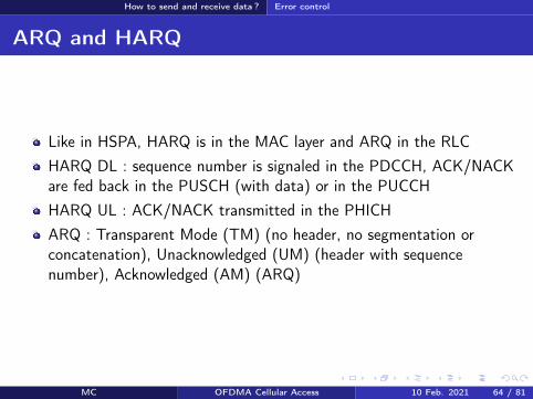
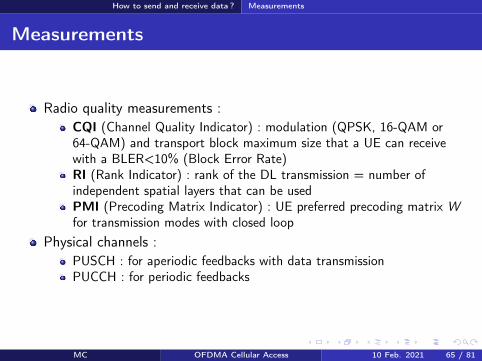

Terminals categories
Terminals categories
Caracteristics Cat 1 Cat 2 Cat 3 Cat 4 Cat 5Max number ofbits per TTI (DL) 10296 51024 102048 150752 299552
Max number ofbits per TTI (UL) 5160 25456 51024 51024 75376
Max data rate(DL) 10 Mbps 50 Mbps 100 Mbps 150 Mbps 300 Mbps
Max data rate(UL) 5 Mbps 25 Mbps 50 Mbps 50 Mbps 75 Mbps
64 QAM (UL) No No No No YesMIMO (DL) Option 2times 2 2times 2 2times 2 4times 4
Table ndash Terminal categories in LTE
For example the Semsong S5 is cat 4 the Semsong S6 is cat 6 (Release 1030050 Mbps) the Semsong S8 is cat1613 (Release 12 1050150 Mbps MIMO4x4 256-QAM 5CA) Semsong S10 is cat 2013 (2000 Mbps up to 8 MIMOlayers 256-QAM 7CA)
MC OFDMA Cellular Access 10 Feb 2021 67 81
Summary on channels
Section 9
Summary on channels
MC OFDMA Cellular Access 10 Feb 2021 68 81
Summary on channels
Physical channels DL I
PDSCH (Physical Downlink Shared Ch) physical shared channel for data
RS (Reference Signals) pilots required to estimate radio quality and toallow decoding on the DL
SS (Synchronization Signals) = PSS (Primary)+SSS (Secondary) for timeand frequency synchronization
PBCH (Physical Broadcast Ch) beacon MIB transmission
PCFICH (Physical Control Format Indicator Ch) tell the UEs how manyOFDM symbols are dedicated to the control part of the sub-frame (CFI)
PDCCH (Physical Downlink Control Ch) control informations (DCI resource allocation UE identity HARQ information MIMO etc)
PHICH (Physical Hybrid ARQ Indicator Ch) ACKNACK responses toHARQ transmissions from a UE (HI)
MC OFDMA Cellular Access 10 Feb 2021 69 81
Summary on channels
Physical channels UL I
In UL a UE is not able to multiplex different physical channels in the frequencydomain because of SC-FDMA limitation rArr time multiplexing is required
DMRS (Demodulation Reference Signal) used by the eNB to estimate thechannel and make radio quality measurements on the signal transmitted by theUE DMRS are sent in conjunction with PUCCH and PUSCH
SRS (Sounding Reference Signal) pilots used by the scheduler for the radioquality estimation on a bandwidth larger than the one allocated to the UE
PUCCH (Physical Uplink Control Ch) control informations UCI includingchannel quality (CQI) MIMO (closed loop) or HARQ (ACKNACK) informations
PUSCH (Physical Uplink Shared Ch) shared physical channels for data andcontrol
If a UE has data to transmit it uses the PUSCH for data and control Otherwiseit uses the PUCCH for the control
MC OFDMA Cellular Access 10 Feb 2021 70 81
Summary on channels
Transport channels DL
DL-SCH (DL Shared Ch) shared channel for data associated toPDSCHPCH (Paging Ch) broadcast of paging messages on the PDSCHBCH (Broadcast Ch) broadcast of system informations (SIBs) onthe PBCH and on the PDSCHDCI (DL Control Indicator) control information transmitted on thePDCCHs (transport format resource allocation HARQ and MIMOinformations power control commands)CFI (Control Format Indicator) number of OFDM symbols (12 or 3)used by PDCCHs at the beginning of every sub-frame CFI is sent onthe PCFICHHI (HARQ Indicator) ACK or NACK in response to a transmissionon the UL-SCH HI is transmitted on the PHICH
MC OFDMA Cellular Access 10 Feb 2021 71 81
Summary on channels
transport channels UL
RACH (Random Access Ch) random accessUL-SCH (UL Share Ch) shared channel for data and controlassociated to PUSCH User data and control informations aremultiplexed in time and frequency on the PUSCHUCI (UL Control Indicator) control information transmitted by thePUCCH (channel quality CQI closed loop MIMO informationsPMIRI ACKNACK of HARQ scheduling request)
MC OFDMA Cellular Access 10 Feb 2021 72 81
Summary on channels
Logical channels
Logical channel Type Description LinkBCCH Control System information DLPCCH Control Paging DLCCCH Control Control without RRC conn ULDLDCCH Controcircle Dedicated control ULDLDTCH Traffic user plane ULDL
Table ndash Logical channels in LTE DL and UL
BCCH (Broadcast COntrol Ch) system information associated to BCH for theMIB and DL-SCH for the SIBs
PCCH (Paging Control Ch) paging associated to PCH
CCCH (Common Control Ch) control messages between the network and UEswithout RRC connection associated to DL-SCH and UL-SCH
DCCH (Dedicated Control Ch) control messages between the network and UEswith RRC connection associated to DL-SCH and UL-SCH
MC OFDMA Cellular Access 10 Feb 2021 73 81
Conclusion
Section 10
Conclusion
MC OFDMA Cellular Access 10 Feb 2021 74 81
Conclusion
Conclusion
LTE A brand new standardA certain simplicity that is reminiscent of GSMSimilarities with 3G (channels HARQ MAC RLC etc)New features (MIMO MU-MIMO multi-carrier transmissions)
After LTE LTE-A R13 frozen in Mar 2016 (LTE Pro) R14 on goingR15 is called 5G New Radio (NR) and is the first 5G releasePeak rates of the order of 1GbpsCarrier aggregation discontinuous resource allocation on the ULMIMO 8times8 relays HetNets CoMP Self-Organized NetworksMBMS NB-IoT etc
MC OFDMA Cellular Access 10 Feb 2021 75 81
Conclusion
References I
3GPPTechnical Specification 36211 Physical channels and modulationDec 2009
3GPPTechnical Specification 36300 Evolved Universal Terrestrial RadioAccess (E-UTRA) and Evolved Universal Terrestrial Radio AccessNetwork (E-UTRAN) Overall description Apr 2010
3GPPTechnical Specification 36104 Base Station (BS) radio transmissionand reception Jun 2011
MC OFDMA Cellular Access 10 Feb 2021 76 81
Conclusion
References II
S M AlamoutiA simple transmit diversity technique for wireless communicationsIEEE J on Selected Areas in Communications 16(8) 1451ndash1458 Oct1998
MC OFDMA Cellular Access 10 Feb 2021 77 81
Conclusion
Acronyms I
AM ARQ Acknowledged ModeARQ Automatic Repeat on RequestBCCH Broadcast Control ChannelBCH Broadcast ChannelBLER Block Error RateBPSK Binary Phase Shift KeyingBS Base Station
CCCH Common Control ChannelCDMA Code Division Multiple AccessCFI Control Format Indocator
CoMP Coordinated Multi-PointCQI Channel Quality IndicatorCRC Cyclic Redundancy CodeD2D Device to DeviceDCCH Dedicated Control ChannelDCI Downlink Control InformationDL Downlink
DL-SCH Downlink Shared ChannelDMRS Demodulation Reference SignalDTCH Dedicated Traffic ChanneleNB eNode-BEPC Evolved Packet Core
E-UTRAN Evolved UTRANFDD Frequency Division DuplexFDPS Frequency Dependent Packet SchedulingFFT Fast Fourier TransformGSM Groupe Speacutecial MobileHARQ Hybrid Automatic Repeat on Request
MC OFDMA Cellular Access 10 Feb 2021 78 81
Conclusion
Acronyms IIHI HARQ Indicator
HSPA High Speed Packet AccessHSDPA High Speed Downlink Packet AccessHSPA High Speed Uplink Packet AccessICI Inter-Carrier InterferenceIFFT Inverse Fast Fourier TransformIMT International Mobile TelecommunicationsISI Inter-Symbol InterferenceLTE Long Term EvolutionMAC Medium Access ControlMBMS Multimedia Broadcast Multicast ServiceMIB Master Information BlockMIMO Multiple Input Multiple OutputMME Mobility Management Entity
MU-MIMO Multi-User MIMONAS Non Access StratumOFDM Orthogonal Frequency Division MultiplexOFDMA Orthogonal Frequency Division Multiple AccessPAPR Peak to Average Power RatioPBCH Physical Broadcast ChannelPCFICH Physical Control Format Indicator ChannelPCCH Paging Control ChannelPCH Paging ChannelPCI Physical Cell Identifier
PDCCH Physical Downlink Control ChannelPDCP Packet Data Convergence ProtocolPDSCH Physical Downlink Shared ChannelPDU Protocol Data Unit
MC OFDMA Cellular Access 10 Feb 2021 79 81
Conclusion
Acronyms IIIPHICH Physical Hybrid ARQ Indicator ChannelPMI Precoding Matrix IndicatorPSS Primary Synchronization Signal
PUCCH Physical Uplink Control ChannelPUSCH Physical Uplink Shared ChannelQAM Qadrature Amplitude ModulationQPSK Quadrature Phase Shift KeyingRACH Random Access ChannelRAR Random Access ResponseRB Resource BlockRE Resource ElementRI Rank IndicatorRLC Radio Link ControlRNC Radio Network ControllerRNTI Radio Network Temporary IdentifierROHC Robust Header CompressionRRC Radio Resource ControlRS Reference Signal
SC-FDMA Single Carrier Frequency Division Multiple AccessSDU Service Data UnitSFBC Space-Time Block CodeSGW Serving GatewaySIB System Information BlockSISO Single Input Single OutputSNR Signal to Noise RatioSRS Sounding Reference SignalSSS Secondary Synchronization SignalTA Timing Advance
MC OFDMA Cellular Access 10 Feb 2021 80 81
Conclusion
Acronyms IV
TDD Time Division DuplexTM Transmission ModeTM ARQ Transparent ModeTTI Transmission Time IntervalUCI Uplink Control InformationUE User EquipmentUM ARQ Unacknowledged Mode
UMTS Universal Mobile Telecommunications SystemUL Uplink
UL-SCH Uplink Shared ChannelUTRAN UMTS Terrestrial Radio Access NetworkWCDMA Wideband Code Division Multiple Access
MC OFDMA Cellular Access 10 Feb 2021 81 81

Summary on channels
Logical channels
Logical channel Type Description LinkBCCH Control System information DLPCCH Control Paging DLCCCH Control Control without RRC conn ULDLDCCH Controcircle Dedicated control ULDLDTCH Traffic user plane ULDL
Table ndash Logical channels in LTE DL and UL
BCCH (Broadcast COntrol Ch) system information associated to BCH for theMIB and DL-SCH for the SIBs
PCCH (Paging Control Ch) paging associated to PCH
CCCH (Common Control Ch) control messages between the network and UEswithout RRC connection associated to DL-SCH and UL-SCH
DCCH (Dedicated Control Ch) control messages between the network and UEswith RRC connection associated to DL-SCH and UL-SCH
MC OFDMA Cellular Access 10 Feb 2021 73 81
Conclusion
Section 10
Conclusion
MC OFDMA Cellular Access 10 Feb 2021 74 81
Conclusion
Conclusion
LTE A brand new standardA certain simplicity that is reminiscent of GSMSimilarities with 3G (channels HARQ MAC RLC etc)New features (MIMO MU-MIMO multi-carrier transmissions)
After LTE LTE-A R13 frozen in Mar 2016 (LTE Pro) R14 on goingR15 is called 5G New Radio (NR) and is the first 5G releasePeak rates of the order of 1GbpsCarrier aggregation discontinuous resource allocation on the ULMIMO 8times8 relays HetNets CoMP Self-Organized NetworksMBMS NB-IoT etc
MC OFDMA Cellular Access 10 Feb 2021 75 81
Conclusion
References I
3GPPTechnical Specification 36211 Physical channels and modulationDec 2009
3GPPTechnical Specification 36300 Evolved Universal Terrestrial RadioAccess (E-UTRA) and Evolved Universal Terrestrial Radio AccessNetwork (E-UTRAN) Overall description Apr 2010
3GPPTechnical Specification 36104 Base Station (BS) radio transmissionand reception Jun 2011
MC OFDMA Cellular Access 10 Feb 2021 76 81
Conclusion
References II
S M AlamoutiA simple transmit diversity technique for wireless communicationsIEEE J on Selected Areas in Communications 16(8) 1451ndash1458 Oct1998
MC OFDMA Cellular Access 10 Feb 2021 77 81
Conclusion
Acronyms I
AM ARQ Acknowledged ModeARQ Automatic Repeat on RequestBCCH Broadcast Control ChannelBCH Broadcast ChannelBLER Block Error RateBPSK Binary Phase Shift KeyingBS Base Station
CCCH Common Control ChannelCDMA Code Division Multiple AccessCFI Control Format Indocator
CoMP Coordinated Multi-PointCQI Channel Quality IndicatorCRC Cyclic Redundancy CodeD2D Device to DeviceDCCH Dedicated Control ChannelDCI Downlink Control InformationDL Downlink
DL-SCH Downlink Shared ChannelDMRS Demodulation Reference SignalDTCH Dedicated Traffic ChanneleNB eNode-BEPC Evolved Packet Core
E-UTRAN Evolved UTRANFDD Frequency Division DuplexFDPS Frequency Dependent Packet SchedulingFFT Fast Fourier TransformGSM Groupe Speacutecial MobileHARQ Hybrid Automatic Repeat on Request
MC OFDMA Cellular Access 10 Feb 2021 78 81
Conclusion
Acronyms IIHI HARQ Indicator
HSPA High Speed Packet AccessHSDPA High Speed Downlink Packet AccessHSPA High Speed Uplink Packet AccessICI Inter-Carrier InterferenceIFFT Inverse Fast Fourier TransformIMT International Mobile TelecommunicationsISI Inter-Symbol InterferenceLTE Long Term EvolutionMAC Medium Access ControlMBMS Multimedia Broadcast Multicast ServiceMIB Master Information BlockMIMO Multiple Input Multiple OutputMME Mobility Management Entity
MU-MIMO Multi-User MIMONAS Non Access StratumOFDM Orthogonal Frequency Division MultiplexOFDMA Orthogonal Frequency Division Multiple AccessPAPR Peak to Average Power RatioPBCH Physical Broadcast ChannelPCFICH Physical Control Format Indicator ChannelPCCH Paging Control ChannelPCH Paging ChannelPCI Physical Cell Identifier
PDCCH Physical Downlink Control ChannelPDCP Packet Data Convergence ProtocolPDSCH Physical Downlink Shared ChannelPDU Protocol Data Unit
MC OFDMA Cellular Access 10 Feb 2021 79 81
Conclusion
Acronyms IIIPHICH Physical Hybrid ARQ Indicator ChannelPMI Precoding Matrix IndicatorPSS Primary Synchronization Signal
PUCCH Physical Uplink Control ChannelPUSCH Physical Uplink Shared ChannelQAM Qadrature Amplitude ModulationQPSK Quadrature Phase Shift KeyingRACH Random Access ChannelRAR Random Access ResponseRB Resource BlockRE Resource ElementRI Rank IndicatorRLC Radio Link ControlRNC Radio Network ControllerRNTI Radio Network Temporary IdentifierROHC Robust Header CompressionRRC Radio Resource ControlRS Reference Signal
SC-FDMA Single Carrier Frequency Division Multiple AccessSDU Service Data UnitSFBC Space-Time Block CodeSGW Serving GatewaySIB System Information BlockSISO Single Input Single OutputSNR Signal to Noise RatioSRS Sounding Reference SignalSSS Secondary Synchronization SignalTA Timing Advance
MC OFDMA Cellular Access 10 Feb 2021 80 81
Conclusion
Acronyms IV
TDD Time Division DuplexTM Transmission ModeTM ARQ Transparent ModeTTI Transmission Time IntervalUCI Uplink Control InformationUE User EquipmentUM ARQ Unacknowledged Mode
UMTS Universal Mobile Telecommunications SystemUL Uplink
UL-SCH Uplink Shared ChannelUTRAN UMTS Terrestrial Radio Access NetworkWCDMA Wideband Code Division Multiple Access
MC OFDMA Cellular Access 10 Feb 2021 81 81

Conclusion
Conclusion
LTE A brand new standardA certain simplicity that is reminiscent of GSMSimilarities with 3G (channels HARQ MAC RLC etc)New features (MIMO MU-MIMO multi-carrier transmissions)
After LTE LTE-A R13 frozen in Mar 2016 (LTE Pro) R14 on goingR15 is called 5G New Radio (NR) and is the first 5G releasePeak rates of the order of 1GbpsCarrier aggregation discontinuous resource allocation on the ULMIMO 8times8 relays HetNets CoMP Self-Organized NetworksMBMS NB-IoT etc
MC OFDMA Cellular Access 10 Feb 2021 75 81
Conclusion
References I
3GPPTechnical Specification 36211 Physical channels and modulationDec 2009
3GPPTechnical Specification 36300 Evolved Universal Terrestrial RadioAccess (E-UTRA) and Evolved Universal Terrestrial Radio AccessNetwork (E-UTRAN) Overall description Apr 2010
3GPPTechnical Specification 36104 Base Station (BS) radio transmissionand reception Jun 2011
MC OFDMA Cellular Access 10 Feb 2021 76 81
Conclusion
References II
S M AlamoutiA simple transmit diversity technique for wireless communicationsIEEE J on Selected Areas in Communications 16(8) 1451ndash1458 Oct1998
MC OFDMA Cellular Access 10 Feb 2021 77 81
Conclusion
Acronyms I
AM ARQ Acknowledged ModeARQ Automatic Repeat on RequestBCCH Broadcast Control ChannelBCH Broadcast ChannelBLER Block Error RateBPSK Binary Phase Shift KeyingBS Base Station
CCCH Common Control ChannelCDMA Code Division Multiple AccessCFI Control Format Indocator
CoMP Coordinated Multi-PointCQI Channel Quality IndicatorCRC Cyclic Redundancy CodeD2D Device to DeviceDCCH Dedicated Control ChannelDCI Downlink Control InformationDL Downlink
DL-SCH Downlink Shared ChannelDMRS Demodulation Reference SignalDTCH Dedicated Traffic ChanneleNB eNode-BEPC Evolved Packet Core
E-UTRAN Evolved UTRANFDD Frequency Division DuplexFDPS Frequency Dependent Packet SchedulingFFT Fast Fourier TransformGSM Groupe Speacutecial MobileHARQ Hybrid Automatic Repeat on Request
MC OFDMA Cellular Access 10 Feb 2021 78 81
Conclusion
Acronyms IIHI HARQ Indicator
HSPA High Speed Packet AccessHSDPA High Speed Downlink Packet AccessHSPA High Speed Uplink Packet AccessICI Inter-Carrier InterferenceIFFT Inverse Fast Fourier TransformIMT International Mobile TelecommunicationsISI Inter-Symbol InterferenceLTE Long Term EvolutionMAC Medium Access ControlMBMS Multimedia Broadcast Multicast ServiceMIB Master Information BlockMIMO Multiple Input Multiple OutputMME Mobility Management Entity
MU-MIMO Multi-User MIMONAS Non Access StratumOFDM Orthogonal Frequency Division MultiplexOFDMA Orthogonal Frequency Division Multiple AccessPAPR Peak to Average Power RatioPBCH Physical Broadcast ChannelPCFICH Physical Control Format Indicator ChannelPCCH Paging Control ChannelPCH Paging ChannelPCI Physical Cell Identifier
PDCCH Physical Downlink Control ChannelPDCP Packet Data Convergence ProtocolPDSCH Physical Downlink Shared ChannelPDU Protocol Data Unit
MC OFDMA Cellular Access 10 Feb 2021 79 81
Conclusion
Acronyms IIIPHICH Physical Hybrid ARQ Indicator ChannelPMI Precoding Matrix IndicatorPSS Primary Synchronization Signal
PUCCH Physical Uplink Control ChannelPUSCH Physical Uplink Shared ChannelQAM Qadrature Amplitude ModulationQPSK Quadrature Phase Shift KeyingRACH Random Access ChannelRAR Random Access ResponseRB Resource BlockRE Resource ElementRI Rank IndicatorRLC Radio Link ControlRNC Radio Network ControllerRNTI Radio Network Temporary IdentifierROHC Robust Header CompressionRRC Radio Resource ControlRS Reference Signal
SC-FDMA Single Carrier Frequency Division Multiple AccessSDU Service Data UnitSFBC Space-Time Block CodeSGW Serving GatewaySIB System Information BlockSISO Single Input Single OutputSNR Signal to Noise RatioSRS Sounding Reference SignalSSS Secondary Synchronization SignalTA Timing Advance
MC OFDMA Cellular Access 10 Feb 2021 80 81
Conclusion
Acronyms IV
TDD Time Division DuplexTM Transmission ModeTM ARQ Transparent ModeTTI Transmission Time IntervalUCI Uplink Control InformationUE User EquipmentUM ARQ Unacknowledged Mode
UMTS Universal Mobile Telecommunications SystemUL Uplink
UL-SCH Uplink Shared ChannelUTRAN UMTS Terrestrial Radio Access NetworkWCDMA Wideband Code Division Multiple Access
MC OFDMA Cellular Access 10 Feb 2021 81 81

Conclusion
References I
3GPPTechnical Specification 36211 Physical channels and modulationDec 2009
3GPPTechnical Specification 36300 Evolved Universal Terrestrial RadioAccess (E-UTRA) and Evolved Universal Terrestrial Radio AccessNetwork (E-UTRAN) Overall description Apr 2010
3GPPTechnical Specification 36104 Base Station (BS) radio transmissionand reception Jun 2011
MC OFDMA Cellular Access 10 Feb 2021 76 81
Conclusion
References II
S M AlamoutiA simple transmit diversity technique for wireless communicationsIEEE J on Selected Areas in Communications 16(8) 1451ndash1458 Oct1998
MC OFDMA Cellular Access 10 Feb 2021 77 81
Conclusion
Acronyms I
AM ARQ Acknowledged ModeARQ Automatic Repeat on RequestBCCH Broadcast Control ChannelBCH Broadcast ChannelBLER Block Error RateBPSK Binary Phase Shift KeyingBS Base Station
CCCH Common Control ChannelCDMA Code Division Multiple AccessCFI Control Format Indocator
CoMP Coordinated Multi-PointCQI Channel Quality IndicatorCRC Cyclic Redundancy CodeD2D Device to DeviceDCCH Dedicated Control ChannelDCI Downlink Control InformationDL Downlink
DL-SCH Downlink Shared ChannelDMRS Demodulation Reference SignalDTCH Dedicated Traffic ChanneleNB eNode-BEPC Evolved Packet Core
E-UTRAN Evolved UTRANFDD Frequency Division DuplexFDPS Frequency Dependent Packet SchedulingFFT Fast Fourier TransformGSM Groupe Speacutecial MobileHARQ Hybrid Automatic Repeat on Request
MC OFDMA Cellular Access 10 Feb 2021 78 81
Conclusion
Acronyms IIHI HARQ Indicator
HSPA High Speed Packet AccessHSDPA High Speed Downlink Packet AccessHSPA High Speed Uplink Packet AccessICI Inter-Carrier InterferenceIFFT Inverse Fast Fourier TransformIMT International Mobile TelecommunicationsISI Inter-Symbol InterferenceLTE Long Term EvolutionMAC Medium Access ControlMBMS Multimedia Broadcast Multicast ServiceMIB Master Information BlockMIMO Multiple Input Multiple OutputMME Mobility Management Entity
MU-MIMO Multi-User MIMONAS Non Access StratumOFDM Orthogonal Frequency Division MultiplexOFDMA Orthogonal Frequency Division Multiple AccessPAPR Peak to Average Power RatioPBCH Physical Broadcast ChannelPCFICH Physical Control Format Indicator ChannelPCCH Paging Control ChannelPCH Paging ChannelPCI Physical Cell Identifier
PDCCH Physical Downlink Control ChannelPDCP Packet Data Convergence ProtocolPDSCH Physical Downlink Shared ChannelPDU Protocol Data Unit
MC OFDMA Cellular Access 10 Feb 2021 79 81
Conclusion
Acronyms IIIPHICH Physical Hybrid ARQ Indicator ChannelPMI Precoding Matrix IndicatorPSS Primary Synchronization Signal
PUCCH Physical Uplink Control ChannelPUSCH Physical Uplink Shared ChannelQAM Qadrature Amplitude ModulationQPSK Quadrature Phase Shift KeyingRACH Random Access ChannelRAR Random Access ResponseRB Resource BlockRE Resource ElementRI Rank IndicatorRLC Radio Link ControlRNC Radio Network ControllerRNTI Radio Network Temporary IdentifierROHC Robust Header CompressionRRC Radio Resource ControlRS Reference Signal
SC-FDMA Single Carrier Frequency Division Multiple AccessSDU Service Data UnitSFBC Space-Time Block CodeSGW Serving GatewaySIB System Information BlockSISO Single Input Single OutputSNR Signal to Noise RatioSRS Sounding Reference SignalSSS Secondary Synchronization SignalTA Timing Advance
MC OFDMA Cellular Access 10 Feb 2021 80 81
Conclusion
Acronyms IV
TDD Time Division DuplexTM Transmission ModeTM ARQ Transparent ModeTTI Transmission Time IntervalUCI Uplink Control InformationUE User EquipmentUM ARQ Unacknowledged Mode
UMTS Universal Mobile Telecommunications SystemUL Uplink
UL-SCH Uplink Shared ChannelUTRAN UMTS Terrestrial Radio Access NetworkWCDMA Wideband Code Division Multiple Access
MC OFDMA Cellular Access 10 Feb 2021 81 81
Conclusion
References II
S M AlamoutiA simple transmit diversity technique for wireless communicationsIEEE J on Selected Areas in Communications 16(8) 1451ndash1458 Oct1998
MC OFDMA Cellular Access 10 Feb 2021 77 81
Conclusion
Acronyms I
AM ARQ Acknowledged ModeARQ Automatic Repeat on RequestBCCH Broadcast Control ChannelBCH Broadcast ChannelBLER Block Error RateBPSK Binary Phase Shift KeyingBS Base Station
CCCH Common Control ChannelCDMA Code Division Multiple AccessCFI Control Format Indocator
CoMP Coordinated Multi-PointCQI Channel Quality IndicatorCRC Cyclic Redundancy CodeD2D Device to DeviceDCCH Dedicated Control ChannelDCI Downlink Control InformationDL Downlink
DL-SCH Downlink Shared ChannelDMRS Demodulation Reference SignalDTCH Dedicated Traffic ChanneleNB eNode-BEPC Evolved Packet Core
E-UTRAN Evolved UTRANFDD Frequency Division DuplexFDPS Frequency Dependent Packet SchedulingFFT Fast Fourier TransformGSM Groupe Speacutecial MobileHARQ Hybrid Automatic Repeat on Request
MC OFDMA Cellular Access 10 Feb 2021 78 81
Conclusion
Acronyms IIHI HARQ Indicator
HSPA High Speed Packet AccessHSDPA High Speed Downlink Packet AccessHSPA High Speed Uplink Packet AccessICI Inter-Carrier InterferenceIFFT Inverse Fast Fourier TransformIMT International Mobile TelecommunicationsISI Inter-Symbol InterferenceLTE Long Term EvolutionMAC Medium Access ControlMBMS Multimedia Broadcast Multicast ServiceMIB Master Information BlockMIMO Multiple Input Multiple OutputMME Mobility Management Entity
MU-MIMO Multi-User MIMONAS Non Access StratumOFDM Orthogonal Frequency Division MultiplexOFDMA Orthogonal Frequency Division Multiple AccessPAPR Peak to Average Power RatioPBCH Physical Broadcast ChannelPCFICH Physical Control Format Indicator ChannelPCCH Paging Control ChannelPCH Paging ChannelPCI Physical Cell Identifier
PDCCH Physical Downlink Control ChannelPDCP Packet Data Convergence ProtocolPDSCH Physical Downlink Shared ChannelPDU Protocol Data Unit
MC OFDMA Cellular Access 10 Feb 2021 79 81
Conclusion
Acronyms IIIPHICH Physical Hybrid ARQ Indicator ChannelPMI Precoding Matrix IndicatorPSS Primary Synchronization Signal
PUCCH Physical Uplink Control ChannelPUSCH Physical Uplink Shared ChannelQAM Qadrature Amplitude ModulationQPSK Quadrature Phase Shift KeyingRACH Random Access ChannelRAR Random Access ResponseRB Resource BlockRE Resource ElementRI Rank IndicatorRLC Radio Link ControlRNC Radio Network ControllerRNTI Radio Network Temporary IdentifierROHC Robust Header CompressionRRC Radio Resource ControlRS Reference Signal
SC-FDMA Single Carrier Frequency Division Multiple AccessSDU Service Data UnitSFBC Space-Time Block CodeSGW Serving GatewaySIB System Information BlockSISO Single Input Single OutputSNR Signal to Noise RatioSRS Sounding Reference SignalSSS Secondary Synchronization SignalTA Timing Advance
MC OFDMA Cellular Access 10 Feb 2021 80 81
Conclusion
Acronyms IV
TDD Time Division DuplexTM Transmission ModeTM ARQ Transparent ModeTTI Transmission Time IntervalUCI Uplink Control InformationUE User EquipmentUM ARQ Unacknowledged Mode
UMTS Universal Mobile Telecommunications SystemUL Uplink
UL-SCH Uplink Shared ChannelUTRAN UMTS Terrestrial Radio Access NetworkWCDMA Wideband Code Division Multiple Access
MC OFDMA Cellular Access 10 Feb 2021 81 81

Conclusion
Acronyms IV
TDD Time Division DuplexTM Transmission ModeTM ARQ Transparent ModeTTI Transmission Time IntervalUCI Uplink Control InformationUE User EquipmentUM ARQ Unacknowledged Mode
UMTS Universal Mobile Telecommunications SystemUL Uplink
UL-SCH Uplink Shared ChannelUTRAN UMTS Terrestrial Radio Access NetworkWCDMA Wideband Code Division Multiple Access
MC OFDMA Cellular Access 10 Feb 2021 81 81