Embed Size (px)
Citation preview
Océ | User Guide
Océ PRISMAtoolsDocument Designer V1.06 Standard Suite

...and Training?For this product we also offer seminars at ourTraining Centre in Poing
For information, please contact:Phone: +49 81 21 72-39 40Fax: +49 81 21 72-39 50
Océ Printing Systems GmbHSiemensallee 285581 PoingGermany
Copyright Océ Printing Systems GmbH 2003, 2004
All rights reserved, including those of translation into other languages.No part of this manual may be reproduced by photocopying, reprinting or any other method.Offenders will be liable for damages. All rights, including rights created by patent grant orregistration of a utility model, are reserved.Delivery subject to availability, subject to change for technical reasons.All hardware and software names are trade names of their respective manufacturers.
April 2004 EditionA29247-X83-X-3-7670

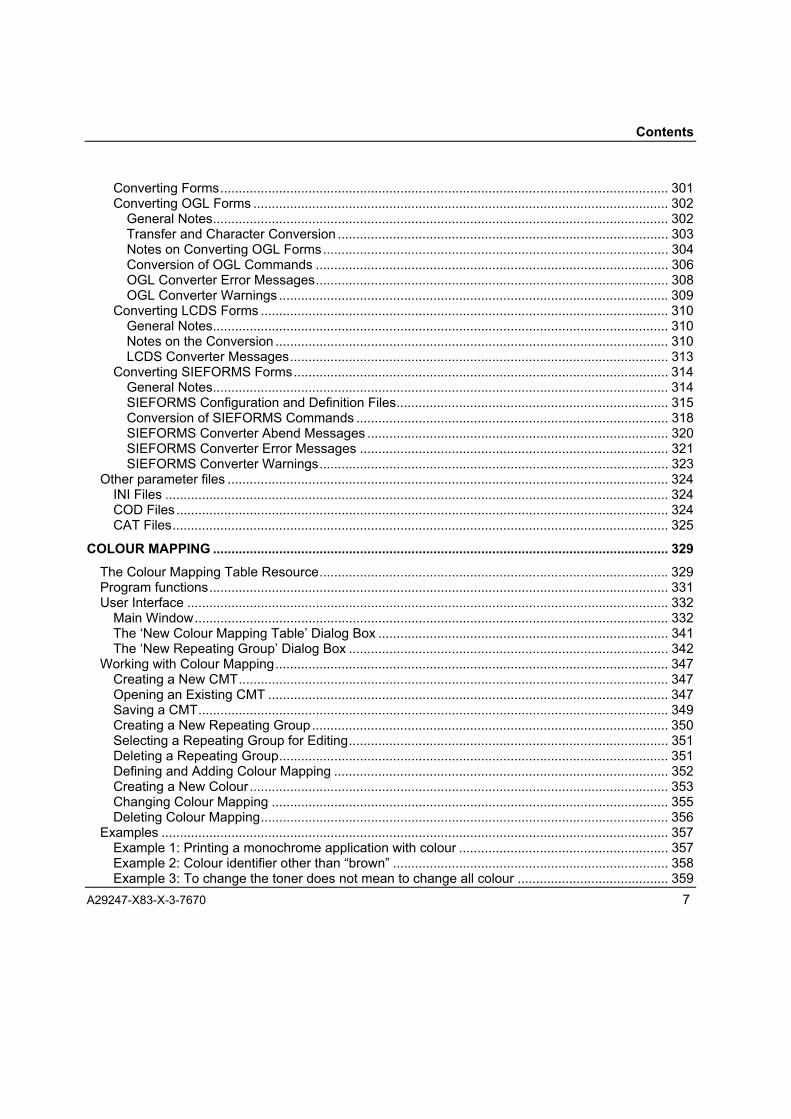
Contents
A29247-X83-X-3-7670 3
ContentsCONTENTS.............................................................................................................................................. 3
APPLICATION SETUP .......................................................................................................................... 11The program functions........................................................................................................................ 13
File management............................................................................................................................. 13Resource transfer............................................................................................................................ 14
The user interface ............................................................................................................................... 15The display field .............................................................................................................................. 15The menu bar .................................................................................................................................. 18
Resource management with Application Setup.................................................................................. 22Setting the resource environment ................................................................................................... 22
Editing resources ................................................................................................................................ 25Editing resources with layout for AFP Line Data............................................................................. 25Editing resources with layout for SAP RDI Data ............................................................................. 26Editing resources with Form Creation............................................................................................. 28Generating resources with Font Creation ....................................................................................... 28
Transferring resources........................................................................................................................ 30Transfer to directory ........................................................................................................................ 30Transfer to ODS Master .................................................................................................................. 31
FONT CREATION .................................................................................................................................. 35Introduction ......................................................................................................................................... 35
Features .......................................................................................................................................... 36Source Fonts ................................................................................................................................... 36Mapping Tables............................................................................................................................... 37
Overview of Font Creation Functions ................................................................................................. 39Font Creation Functions.................................................................................................................. 39Font Header .................................................................................................................................... 39Type Characters.............................................................................................................................. 39Mapping Table................................................................................................................................. 40Font Output Formats ....................................................................................................................... 40
Unicode fonts............................................................................................................................... 41Font Creation User Interface .............................................................................................................. 42
Main Font Creation Window............................................................................................................ 42Font Creation Mapping Editor Window ........................................................................................... 47
Working with Font Creation ................................................................................................................ 50

Contents
4 A29247-X83-X-3-7670
Launching Font Creation................................................................................................................. 51Setting Parameters for Generating Fonts ....................................................................................... 51Selecting a Source Font.................................................................................................................. 56Mapping Type1 to Unicode ............................................................................................................. 59Selecting a Mapping Table.............................................................................................................. 62Editing Mapping Tables................................................................................................................... 66Setting Properties............................................................................................................................ 68Assembling the List of Fonts to Generate....................................................................................... 70Defining the Font Size..................................................................................................................... 72Defining Font File Names................................................................................................................ 73Modifying the Font Header.............................................................................................................. 74Generating Fonts............................................................................................................................. 86
About TrueType Fonts ........................................................................................................................ 89Fonts on the Printer Hard Disk ........................................................................................................... 94
Resident Fonts ................................................................................................................................ 94Installed Fonts ................................................................................................................................. 94
Installing Fonts............................................................................................................................. 94Deleting Installed Fonts ............................................................................................................... 95Selecting the Default Font ........................................................................................................... 96
Captured Fonts................................................................................................................................ 97
FONT IMPORT..................................................................................................................................... 101Introduction ....................................................................................................................................... 101FontsInfobase Browser..................................................................................................................... 102
User Interface................................................................................................................................ 102Deleting fonts from FontsInfobase ................................................................................................ 105Adding fonts to FontsInfobase ...................................................................................................... 105
AFP Font Info Generator .................................................................................................................. 106User Interface................................................................................................................................ 106Working with AFP Font Info Generator ......................................................................................... 109
Edit Mapping Table.................................................................................................................... 111LCDS Font Utility .............................................................................................................................. 114
LCDS Font Utility Conversion Settings ......................................................................................... 114LCDS Font Utility Advanced Settings............................................................................................ 118LCDS Font Utility Logging............................................................................................................. 120Working with LCDS Font Utility ..................................................................................................... 121
FORM CREATION ............................................................................................................................... 125Develop High-Class Forms Professionally ....................................................................................... 125The Form Creation program ............................................................................................................. 126How Form Creation Works ............................................................................................................... 129
Program Structure......................................................................................................................... 129Form Creation Editor ..................................................................................................................... 129Fonts in the Form .......................................................................................................................... 130Resource Generators.................................................................................................................... 131Hints .............................................................................................................................................. 131

Contents
A29247-X83-X-3-7670 5
User Interface ................................................................................................................................... 133Main window.................................................................................................................................. 133
Windows Application Border...................................................................................................... 134Menu Bar ................................................................................................................................... 135Toolbox Field ............................................................................................................................. 144Workspace................................................................................................................................. 144
Tools.............................................................................................................................................. 145Pointer Tool ............................................................................................................................... 145Graphic Tools ............................................................................................................................ 145Text Tools .................................................................................................................................. 145OLE Tools.................................................................................................................................. 146
Resource Generators ....................................................................................................................... 147SPDS Generator ........................................................................................................................... 150PCL Macro Generator ................................................................................................................... 163LCDS Generator............................................................................................................................ 173
Working with Form Creation ............................................................................................................. 187Setting Preferences for the Work Environment............................................................................. 187
Selecting the Interface Language.............................................................................................. 187Setting Rulers ............................................................................................................................ 187Adjusting the Grid ...................................................................................................................... 189Displaying the Crosshair............................................................................................................ 190Displaying the Toolbox Field ..................................................................................................... 190Displaying the Position Window ................................................................................................ 191
Settings for Formatting Forms and Generating Overlays ............................................................. 191Choose Printer........................................................................................................................... 191Page Setup ................................................................................................................................ 193
Defaults for Editing Elements........................................................................................................ 194Setting for Duplicating Elements ............................................................................................... 194Settings for Colour Mode........................................................................................................... 195
Defaults for Formatting Elements.................................................................................................. 201Line Settings .............................................................................................................................. 201Setting the Corners.................................................................................................................... 204Setting the Fill Pattern ............................................................................................................... 207Settings for Margins and Rotation ............................................................................................. 210Settings for Formatting Paragraphs .......................................................................................... 212Setting the Element Colour........................................................................................................ 215
Creating, Opening and Saving Forms........................................................................................... 217New Form .................................................................................................................................. 217Opening a Form......................................................................................................................... 217Saving a Form ........................................................................................................................... 218Properties of Forms ................................................................................................................... 220Importing Forms......................................................................................................................... 221Loading and Displaying Background Images............................................................................ 221
Working with the Form Creation Tools.......................................................................................... 223Drawing Boxes........................................................................................................................... 225Drawing Circles and Ellipses..................................................................................................... 225

Contents
6 A29247-X83-X-3-7670
Drawing Lines............................................................................................................................ 226Drawing Polylines ...................................................................................................................... 226Drawing Read Lines .................................................................................................................. 229Entering Text ............................................................................................................................. 231Editing Text................................................................................................................................ 234Merging Text.............................................................................................................................. 235Merging Paragraphs .................................................................................................................. 237Creating and Editing OLE Objects ............................................................................................ 238
Importing Elements ....................................................................................................................... 241Importing Text............................................................................................................................ 242Importing Graphics .................................................................................................................... 243Importing Objects ...................................................................................................................... 244External References .................................................................................................................. 245
Editing Elements ........................................................................................................................... 247Selecting Elements.................................................................................................................... 247Moving Elements ....................................................................................................................... 248Resizing Elements..................................................................................................................... 250Copying Elements ..................................................................................................................... 250Cutting Elements ....................................................................................................................... 251Inserting Elements..................................................................................................................... 251Duplicating Elements................................................................................................................. 251Replicating Elements................................................................................................................. 252Aligning Elements...................................................................................................................... 253Arranging Elements ................................................................................................................... 254Deleting Elements ..................................................................................................................... 255Formatting Elements ................................................................................................................. 255Formatting Imported Images ..................................................................................................... 257Formatting OLE Objects ............................................................................................................ 263
Proof Printing................................................................................................................................. 265Generating Print Resources.......................................................................................................... 266
Generating an SPDS Overlay.................................................................................................... 266Generating a PCL Macro........................................................................................................... 267Generating an LCDS Overlay.................................................................................................... 268
Transfer to the Printing System..................................................................................................... 271Transferring SPDS Resources .................................................................................................. 271Transferring PCL Resources..................................................................................................... 272Transferring LCDS Resources .................................................................................................. 272
FORM IMPORT.................................................................................................................................... 275Overview ........................................................................................................................................... 275Program start .................................................................................................................................... 277User Interface ................................................................................................................................... 279
The Conversion Tab...................................................................................................................... 280The Log View Tab ......................................................................................................................... 288The Settings Tab........................................................................................................................... 291
Working with Form Import................................................................................................................. 301
Contents
A29247-X83-X-3-7670 7
Converting Forms.......................................................................................................................... 301Converting OGL Forms ................................................................................................................. 302
General Notes............................................................................................................................ 302Transfer and Character Conversion .......................................................................................... 303Notes on Converting OGL Forms.............................................................................................. 304Conversion of OGL Commands ................................................................................................ 306OGL Converter Error Messages................................................................................................ 308OGL Converter Warnings .......................................................................................................... 309
Converting LCDS Forms ............................................................................................................... 310General Notes............................................................................................................................ 310Notes on the Conversion ........................................................................................................... 310LCDS Converter Messages....................................................................................................... 313
Converting SIEFORMS Forms...................................................................................................... 314General Notes............................................................................................................................ 314SIEFORMS Configuration and Definition Files.......................................................................... 315Conversion of SIEFORMS Commands ..................................................................................... 318SIEFORMS Converter Abend Messages .................................................................................. 320SIEFORMS Converter Error Messages .................................................................................... 321SIEFORMS Converter Warnings............................................................................................... 323
Other parameter files ........................................................................................................................ 324INI Files ......................................................................................................................................... 324COD Files...................................................................................................................................... 324CAT Files....................................................................................................................................... 325
COLOUR MAPPING ............................................................................................................................ 329The Colour Mapping Table Resource............................................................................................... 329Program functions............................................................................................................................. 331User Interface ................................................................................................................................... 332
Main Window................................................................................................................................. 332The �New Colour Mapping Table� Dialog Box ............................................................................... 341The �New Repeating Group� Dialog Box ....................................................................................... 342
Working with Colour Mapping........................................................................................................... 347Creating a New CMT..................................................................................................................... 347Opening an Existing CMT ............................................................................................................. 347Saving a CMT................................................................................................................................ 349Creating a New Repeating Group................................................................................................. 350Selecting a Repeating Group for Editing....................................................................................... 351Deleting a Repeating Group.......................................................................................................... 351Defining and Adding Colour Mapping ........................................................................................... 352Creating a New Colour.................................................................................................................. 353Changing Colour Mapping ............................................................................................................ 355Deleting Colour Mapping............................................................................................................... 356
Examples .......................................................................................................................................... 357Example 1: Printing a monochrome application with colour ......................................................... 357Example 2: Colour identifier other than �brown� ........................................................................... 358Example 3: To change the toner does not mean to change all colour ......................................... 359

Contents
8 A29247-X83-X-3-7670
Example 4: Grey scales or �black and white�................................................................................ 360Example 5: Another way to print diagrams ................................................................................... 361Example 6: Highlight Colour to another Highlight Colour ............................................................. 362Example 7: Conversion to CMYK.................................................................................................. 363
CMT Syntax ...................................................................................................................................... 364Colour Spaces .................................................................................................................................. 367
Highlight Colour............................................................................................................................. 367Standard OCA Colour ................................................................................................................... 368GOCA Pattern Fill.......................................................................................................................... 368The CMYK Colour Space.............................................................................................................. 369The RGB Colour Space ................................................................................................................ 369The CIELAB Colour Space ........................................................................................................... 370
APPENDIX ........................................................................................................................................... 371Appendix 1: Installation Notes .......................................................................................................... 371
A1.1 Hardware and Software Requirements ................................................................................ 371A1.2 Installation Options ............................................................................................................. 372
A1.2.1 Form Creation .............................................................................................................. 372Appendix 2: Error Messages ............................................................................................................ 375
A2.1 Font Creation ........................................................................................................................ 375A2.2 Form Creation....................................................................................................................... 377A2.3 Reporting Errors to Océ Service......................................................................................... 379
GLOSSARY ......................................................................................................................................... 381
FURTHER REFERENCE ..................................................................................................................... 398
INDEX................................................................................................................................................... 399

Application Setup
A29247-X83-X-3-7670 9
APPLICATIONSETUP


Application Setup
A29247-X83-X-3-7670 11
Application SetupPRISMA printing systems use the following resources for printing variable data:
• PageDef (definition of the page layout),
• FormDef (definition of the print format),
• Fonts (character sets for the fonts used),
• Overlays (forms to be overprinted),
• Page Segments (text and graphical components).
These print resources are produced using programs in the Océ Document DesignerStandard Suite and are compiled individually for the various print jobs. For the print jobs,the resources need to be fully and consistently available in the printing system.
Application Setup is a tool for managing print resources. Application Setup assists instoring the resource files in an ordered way and transferring them to the printing systemconsistently.
In accordance with the programs for producing and importing resources, ApplicationSetup controls the storage of the files generated, ordered by application in the specifiedfolder within the development environment. When resource files are generated, theprograms also store a file containing a list of all resources used for the application (*.rsl).


Program Functions Application Setup
A29247-X83-X-3-7670 13
The program functionsApplication Setup assists you in managing the files for print resources developed usingOcé Document Designer and in transferring the resources to the printing system.
File management
In Application Setup, the PRISMA resources file directories are defined for working withOcé Document Designer.
In Application Setup you specify in which folders the files from a specific application canbe found and the folder in which resources generated for the application are stored.Working with Application Setup, the resource generators of the Océ Document Designeraccess the folder specified in Application Setup.
Application Setup uses a fixed folder hierarchy. In a base directory, folders are specifiedfor your applications and for the application-specific resources used in the applications.
A set up directory structure is known as a resource environment and is saved as such.Application Setup can manage multiple environments, and users can activate any numberof them.
During the installation process for the Application Setup program, a default resourceenvironment is created with a base directory specified during the installation process. Theselected example applications, the resolution-independent resources, and the resolution-specific resources are installed in this directory in three folders for the resolutions 240,300 and 600 dpi.
Fig. 1: Sample Application Setup folder structure
This environment can be used for your own applications. However, you can also use anyfile management program (such as Windows Explorer) to create your own base
Application Setup Program Functions
14 A29247-X83-X-3-7670
directories and link them into your own environments. The base directory can be namedanything you like.
The application folders are normally located immediately after the base directory. Anydirectory hierarchies are permitted between the base directory and the applicationfolders, but only certain subdirectories are supported in the program search functions.
In addition, Application Setup supports a common directory in any environment; thiscan house resources which need to be accessible to all applications.
A special font directory is also supported, which can house the cross-application fontsand font information files.
The main application resources (Formdef/Pagedef and the associated resource list)must always be located directly in an application folder. Exclusively resolution-independent resources are also located in the application folders and in the commondirectory.
Resolution-specific resources are stored by the resource generators in the resolutiondirectories which are on a lower hierarchy level to the application folders. These arenamed with the relevant dpi-number (e.g. /300/). The decision on resolutionindependence/dependence is made by the user or by the resource generator inquestion.
Resource transfer
Application Setup can be used to transfer the resources of an application consistently to aseparate folder or directly to the ODS Master.

User Interface Application Setup
A29247-X83-X-3-7670 15
The user interface
Fig. 2: Main Application Setup window
The Application Setup user interface consists of the following:
• The main window with a two-part display field,
• The menu bar,
• The status bar.
The display field
In the left-hand section of the display field is the folder hierarchy for the set base directory.The resource lists are also displayed here with a green folder icon.
The files in the folder selected on the left are displayed in the right-hand section of thedisplay panel. The resource lists are also shown here with a green folder icon.
Application Setup User Interface
16 A29247-X83-X-3-7670
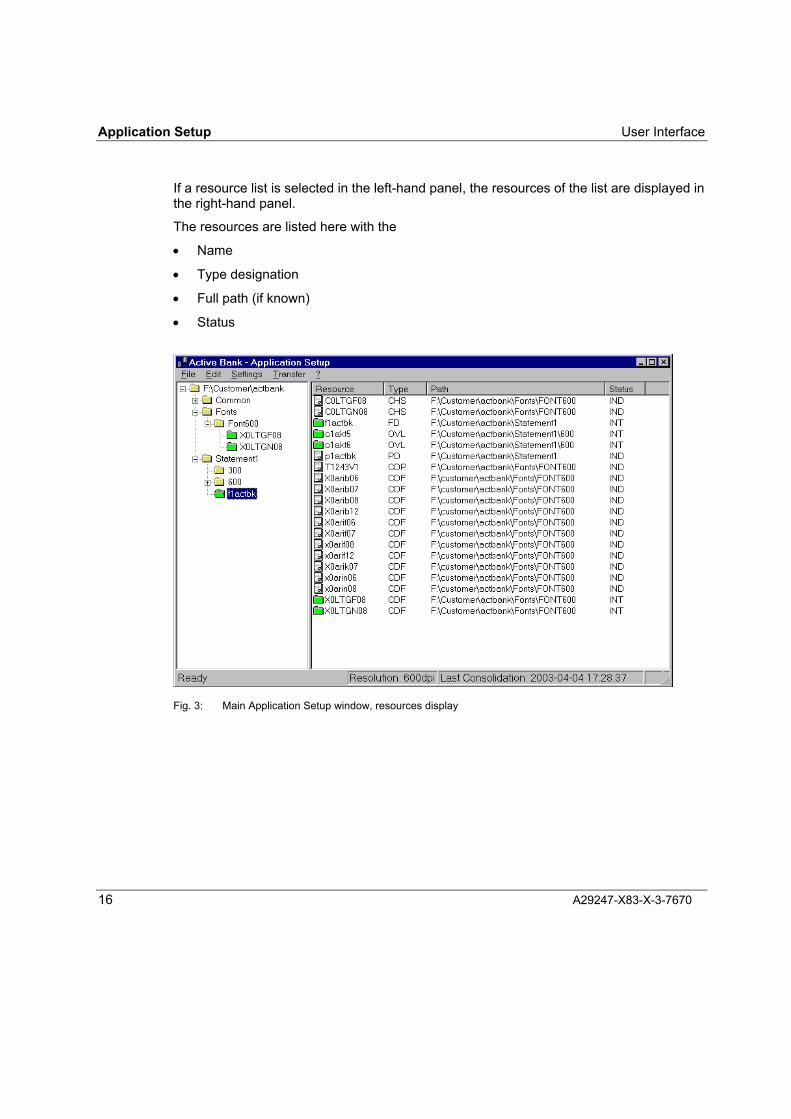
If a resource list is selected in the left-hand panel, the resources of the list are displayed inthe right-hand panel.
The resources are listed here with the
• Name
• Type designation
• Full path (if known)
• Status
Fig. 3: Main Application Setup window, resources display

User Interface Application Setup
A29247-X83-X-3-7670 17
Resources containing references to other resources are displayed with green folder iconsin the resource list.
The folders and files of the applications in the display area are for viewing only. Nochanges can be made to the file structure here. It is only possible to select the basedirectory and create a new application folder using menu functions. Folders and files canonly be moved or deleted using a file management program such as Windows Explorer.
TypeThe type of resource file is given here. The following resource types are now supported:
CDF CodedFontCHS CharacterSetCDP CodePageFD FormDefOVL OverlayPD PageDefPSG Page-SegmentRCI RDI-Formatter Instructions
StatusMeanings of abbreviations in the �Status� column:
INT: Internal, i.e. the resource is stored in the current folder; the resource containsreferences to other resources
IND: Internal, standalone, i.e. it is stored in the current folder; contains noreferences to other resources
EXT: External, i.e. the resource is not available in the current folder.
PathThe complete resource path is displayed here once a consolidation process has takenplace. The result of the consolidation process is displayed here and saved permanently ina file (*.rslc).

Application Setup User Interface
18 A29247-X83-X-3-7670
The menu bar
The menu bar contains the following menus:
• File
• Edit
• Settings
• Transfer
• ?
File menu:The File menu contains the functions:
• New Application
• Exit
New Application is active if the base directory or an application folder has been selectedin the base directory. New Application is used to create a new application folder under theselected directory. The new folder is created with the name �NewApplication�. This namecan be changed to anything you like.If a resolution-specific folder (name �240�, �300� or �600�) or no folder is selected, the NewApplication function is inactive.It is not possible to undo the creation of a new application folder here. Application folderscan also be created and deleted using a file management program such as WindowsExplorer or using the functions in the standard Windows file dialog.
Exit is used to exit Application Setup; in other words, close the program.
Edit menu:The Edit menu contains the functions:
• Consolidate
• Check Consistency
• Refresh
User Interface Application Setup
A29247-X83-X-3-7670 19
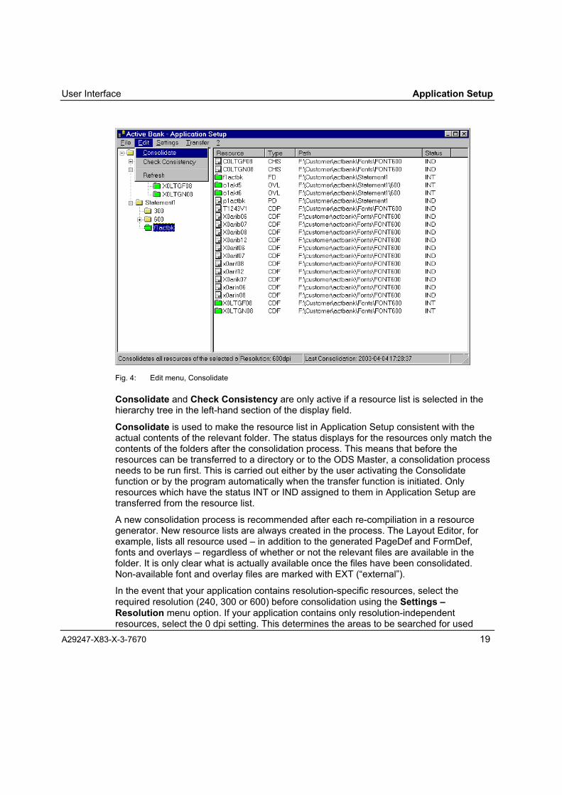
Fig. 4: Edit menu, Consolidate
Consolidate and Check Consistency are only active if a resource list is selected in thehierarchy tree in the left-hand section of the display field.
Consolidate is used to make the resource list in Application Setup consistent with theactual contents of the relevant folder. The status displays for the resources only match thecontents of the folders after the consolidation process. This means that before theresources can be transferred to a directory or to the ODS Master, a consolidation processneeds to be run first. This is carried out either by the user activating the Consolidatefunction or by the program automatically when the transfer function is initiated. Onlyresources which have the status INT or IND assigned to them in Application Setup aretransferred from the resource list.
A new consolidation process is recommended after each re-compiliation in a resourcegenerator. New resource lists are always created in the process. The Layout Editor, forexample, lists all resource used � in addition to the generated PageDef and FormDef,fonts and overlays � regardless of whether or not the relevant files are available in thefolder. It is only clear what is actually available once the files have been consolidated.Non-available font and overlay files are marked with EXT (�external�).
In the event that your application contains resolution-specific resources, select therequired resolution (240, 300 or 600) before consolidation using the Settings �Resolution menu option. If your application contains only resolution-independentresources, select the 0 dpi setting. This determines the areas to be searched for used

Application Setup User Interface
20 A29247-X83-X-3-7670
resources during a consolidation process.When preselecting a specific resolution, the set application folders, the directories storedin the resource environment under Common and Fonts as well as the relevant lower levelresolution directory (240, 300 oder 600) are searched.If 0 dpi is selected, the application folder, all directories immediately underneath it (exceptthose called 240, 300, 600) and the directories stored in the resource environment underCommon and Fonts are searched.
The result of the consolidation process is saved in a special resource list. This has the filetype *.rslc, and contains the path specifications along with the date of the lastconsolidation process. To open a resource list in Application Setup, the consolidated list isdisplayed first, if available, otherwise the original (unconsolidated) *.rsl created by theresource generator is displayed. When a new consolidation process is started, theseoriginal *.rsl files are always used for checking purposes first.
The option Check Consistency allows you to check whether or not the paths entered forthe last consolidation process are still valid. This is useful if you know that no changeshave been made to the application itself. Only the information entered in the *.rslc ischecked in this case. If no consolidation process has been carried out, this option isinactive.
The option Refresh re-checks the entire directory structure and then displays the updatedviews.
Settings menu:The Settings menu contains the functions:
• Environment
• Transfer Server
• Language --> English
• Resolution
Activating the Environment option opens the �Set Resource Environment� dialog. Thesettings that can be made in this dialog window are described in the �Workspace forResource Creation� section.
The Transfer Server option opens the �Transfer Server� dialog.

User Interface Application Setup
A29247-X83-X-3-7670 21
Fig. 5: Set Transfer Server dialog
This dialog is used to enter the name of the server to be used to transfer the resources tothe printing system. This may be either an IP address or an ALIAS name of a PRISMAV3.0 server. For a server group, this should be the server configured as the ODS Master.The TCP/IP link and the server are not checked in this case.
The Language --> English option switches the user interface language from German toEnglish. In the English user interface this option is called Language --> German, whichcan be used to switch from English to German.
Transfer menu:The Transfer menu contains the functions:
• In Folder
• To ODS MasterThese two functions are only active if a resource list is selected in the hierarchy tree in theleft-hand part of the display field.
In Folder is used to open the �Open� dialog where a target folder for the resources can beselected or created. The �Transfertarget� filename in the dialog is a placeholder only; thisname has no bearing on the selection of a target folder.
Clicking the �Open� button activates the transfer of the resources into the selected orcreated folder. The consolidated resource list *.rslc is transferred to the target folder alongwith the resources. The completed transfer is confirmed with the message �Transfer hasbeen completed successfully�.
To ODS Master triggers the transfer of the resources to the transfer server defined in theSettings menu under Transfer Server.
? menu:The ? menu can be used to call up information on the current program or the online helpfor using Application Setup.

Application Setup Setting the Resource Environment
A29247-X83-X-3-7670 22
Resource management with Application Setup
Setting the resource environment
As the resource environment, you specify in Application Setup which folders and files theresource generators of the Océ Document Designer access when creating or editingresources.
To set the resource environment, open the �Set resource environment� dialog using theEnvironment option in the Settings menu.
Fig. 6: �Set resource environment� dialog
Make the following settings in the fields in the �Set resource environment� dialog:
Name:
Selection box with the name of the current resource environment.
Setting the Resource Environment Application Setup
A29247-X83-X-3-7670 23
⇒ Here you can select from existing resource environments or define a new resourceenvironment.
⇒ To define a new resource environment, click on the �New� button. The name �New� isgiven here by default, which you can change to any name you want. The resourceenvironment is stored in Application Setup under the name specified here and isavailable for selection afterwards.
⇒ To select an existing resource environment, select the relevant name and click OK.The selected resource environment is active only once you click OK.
⇒ To delete the defined resource environment, select the relevant name and click�Delete�. The active environment cannot be deleted.
Base:Base directory for the resource environment.
⇒ Clicking the � button opens the �Search Folder� dialog where you can search for andselect a suitable folder.
Curr. Appl.:Folder for the current application in the base directory.
⇒ Clicking the � button opens the �Search Folder� dialog where you can select anapplication folder in the base directory folder (e.g. .\Application1).
Fonts:Full path of the font library for resolution-independent (outline) fonts.
240: Full path of the font library for 240dpi fonts.300: Full path of the font library for 300dpi fonts.600: Full path of the font library for 600dpi fonts.
⇒ Clicking the � button opens the �Open� dialog where you can search for and select afont library. The filename given by default is �fonts.sum�, i.e. in the selected directory afile of this type must be present.
Note: FONTS.SUM is a file containing the font directory of the Form Creationprogram (formerly FGL). This is also formed from the font information files (INFfiles) required in these directories and the corresponding rendering tables(COD files).
The settings for these font libraries in Application Setup and in Form Creation itself are notsynchronised, i.e. Form Creation always works using the font library set in the relevantdriver, regardless of the setting in Application Setup.

Application Setup Setting the Resource Environment
24 A29247-X83-X-3-7670
LE fonts:Full path of the font library (DBS file) for the draft layout with Layout for AFP Line Data orLayout for SAP RDI Data.
⇒ Clicking the � button opens the �Open� dialog where you can search for and select asuitable file. Clicking the �Open� button in the �Open� dialog as well will transfer the fullpath of the selected file into the resource environment.
Setting this font library in Application Setup means that the corresponding option is notrequired in the layout programs. The programs �Layout for AFP Line Data� and �Layout forSAP RDI Data� automatically use the font library set in Application Setup.
Common:Folder for commonly used resources within the resource environment.
⇒ Clicking the � button opens the �Search Folder� dialog where you can select a folder(e.g. c:\environment1\general). This folder is used to store resolution-independentresources. Resolution-specific resources are set up in resolution-specific foldersunderneath this folder.
Clicking �OK� closes the �Set resource environment� dialog and applies the settings. Theresource generators in Océ Document Designer are active following a restart with the setfolders.
Clicking �Cancel� closes the �Set resource environment� dialog without applying thechanges made to the settings. The original folders set will still be valid.

Editing Resources Application Setup
A29247-X83-X-1-7670 25
Editing resourcesThe resource generators described below normally allow you to change to any folders andfiles during loading and saving.
Exiting the environment set up in Application Setup, especially when generating(compiling) the print resources results means, however, that it is no longer possible toguarantee a controlled transfer of an entire application (i.e. all resources used in it).
Editing resources with layout for AFP Line Data
Layout for AFP Line Data uses � if Application Setup is installed � the base directory setin Application Setup and the current application folder for the GRF files to be edited, alongwith the FormDef and PageDef files to be generated and the associated resource lists. Inaddition, changing the application folder when opening or saving an application in Layoutfor AFP Line Data means that this folder becomes the current application folder.
Layout for AFP Line Data uses the settings in Application Setup when started. Changes tothe settings made in Application Setup whilst Layout for AFP Line Data is open, are activein the program immediately.
Note: GRF files contain the saved formatting rules made in Layout for AFP Line Data(formerly SLE).
New applicationThe �New Document� function (button or File/New menu option) creates a new standarddocument with no name. When saving a new document, the �Save As� dialog isautomatically opened where the base directory is set as the current environment. Hereyou can create a new application folder and save the application in it, or select an existingapplication folder if you want to store just one changed definition for an existingapplication.
The specified application folder becomes the current application folder if it is located withinthe base directory.
There should be a separate application folder for each application to be made available onthe productive system. The name of this folder is also used later to identify the applicationon the productive system; the name should therefore be chosen with care. It is possible tocreate multiple versions of an application folder, but these cannot exist simultaneously onthe productive system (ODS Master).
Open application

Application Setup Editing Resources
26 A29247-X83-X-3-7670
The �Open Document� function (button or menu option File/Open...) is used to open thedialog to select an existing application. The application folder last used in connection withApplication Setup is the default folder. If a different application folder is selected in thebase directory, this folder will be the current application folder.
The available GRF files are located in the application folders. Clicking OK will open theselected GRF file for editing.
Save applicationThe Save As... function in the File menu is used to open the dialog for saving thedefinitions under a new name. This saves a GRF file with the name entered. The currentapplication folder is the default folder for saving. If a new application folder in the basedirectory is created or a different folder is selected for saving, this folder will become thecurrent application folder.
Select formsWhen selecting a form for display in the draft layout, Layout for AFP Line Data accessesthe application folders located in the set base directory as well as the subdirectories theycontain. Only graphics files with the extensions *.wmf or *.emf are supported.
Select fontsWhen selecting fonts, Layout for AFP Line Data only accesses the font library set inApplication Setup via LE fonts. It is not possible to select a different font library in theOptions/Environment/Fonts menu in the program. This database only provides the rasterfonts corresponding to the resolution set in the program.
Compile applicationThe �Generate printer resource� function (button or menu option Compiler/Compile orfunction key F9) is used to generate the printer resources FormDef and PageDef as wellas the resource list. All generated data is stored in files in the current application folder.
Editing resources with layout for SAP RDI Data
For all functions where files are loaded or saved, Layout for SAP RDI Data accesses � ifApplication Setup is installed � the application folder of the current base directory set inApplication setup when the program is started. Layout for SAP RDI Data allows you tochange to any folders and files for loading and saving.
This relates to file selection in the menu functions File - Open, File - Save As, File �Generate Print Resources and Data - Connection.

Editing Resources Application Setup
A29247-X83-X-3-7670 27
A separate application folder should be created for each application to be made availableon the productive system. The name of this folder is also used later to identify theapplication on the productive system; the name should therefore be chosen with care. It ispossible to create multiple versions of an application folder, but these cannot existsimultaneously on the productive system (ODS Master).
Select formsWhen selecting a form for display in the draft layout, the form selection in the LayoutEditor of Layout for AFP Line Data accesses the application folders located in the setbase directory as well as the subdirectories they contain. Only graphics files with theextensions *.wmf or *.emf are supported.
Select fontsWhen selecting fonts, Layout for SAP RDI Data only accesses the database set inApplication Setup via LE fonts. Unlike Layout for AFP Line Data, Layout for SAP RDI Dataonly works with resolution-independent fonts (Unicoded Outline Fonts). This is why settinga resolution is not necessary.
Compile resourcesThe function �Generate Printer Resources� is used to generate the printer resourcesFormDef and PageDef, the resource list, along with the RCI file containing the formattinginstructions for the RDI formatter. All generated files are stored in the current applicationfolder.

Application Setup Editing Resources
28 A29247-X83-X-3-7670
Editing resources with Form Creation
For all functions where files are loaded or saved and where the SPDS resource generatoris set, Form Creation accesses � if Application Setup is installed � the application folder ofthe current base directory set in Application setup when the program is started. FormCreation allows you to change to any folders and files for loading and saving.
This relates to file selection in the menu functions File - Open, File - Save As and Data -Write Overlay. In this process a subdirectory with the resolution currently set in FormCreation is created or opened.
Select fontsWhen selecting fonts, Form Creation accesses the font directory defined in the currentgenerator for the resolution set. The setting relating to the font directories in the currentApplication Setup environment is ignored by Form Creation.
Insert | External References...:The File/Open dialog for selecting pictures as placeholders for external references inForm Creation is opened using a preselected, resolution-specific application folders. Withthe Reference Name box, a file selection dialog can be started for page segments insteadof entering the name as free text. The resolution-specific application directory is also set inthis dialog.
Compile resourcesIn the �Write Overlay� function, Form Creation generates, in addition to the OVL file and �if required � the WMF file and EMF file, a resource list in an RSL file stored under thesame name as the OVL file in the same folder.
Generating resources with Font Creation
When generating resolution-specific font resources, Font Creation accesses � ifApplication Setup is installed � the font directory set for this resolution in Application Setupwhen the program is started (see �Set resource environment� chapter, fonts 240, 300,600). Font Creation allows you to change to any folders and files for loading and saving.
When generating resolution-independent font resources (SPDS Outline), Font Creationoffers the font directory set in Application Setup when the program is started. (see �Setresource environment� chapter, fonts). It is possible to change to any other directory here,too.

Editing Resources Application Setup
A29247-X83-X-3-7670 29
The font information files are always transferred into the relevant font libraries set inApplication Setup in the current resource environment (see �Set resource environment�chapter, 240,300,600 and LE fonts), regardless of where the resource files are located.
Note: For the transfer of font information files to function correctly, it is essential thata valid directory is set up in the current resource environment for all resolutions

Application Setup Transferring resources
30 A29247-X83-X-3-7670
Transferring resourcesThe resources listed in Application Setup and available in the application folder can betransferred into a separate directory or directly to the ODS Master using the Transfermenu.
Transfer to directory
Once a resource record has been generated, it can be transferred to an external directory.Before transfer, a consolidation process is run automatically by Application Setup if it hasnot already been carried out. The In Folder function in the Transfer menu is used to openthe �Open� dialog where a target folder for the resources can be selected or created. Thefilename and file type in the Open dialog are not important, and �Transfertarget� will begiven in the file name box as a placeholder.
Fig. 7: Resource transfer to a directory
Clicking the �Open� button will activate the transfer process to the specified directory. Anyexisting files in the target directory with the same name will be overwritten without aprompt.

Transferring resources Application Setup
A29247-X83-X-3-7670 31
If the resource list contains names of resources not present in the application folder, thecorresponding error messages will be displayed. The result of the transfer � successful orwith errors � is displayed at the end of the process.
The consolidated resource list (rslc file) is also transferred and stored in the targetdirectory.
Transfer to ODS Master
Once a resource record has been generated, it can be transferred to a PRISMAproductionV3 printing system. The ODS Master must be defined in advance in the Settings menuunder Transfer Server. The To ODS Master function from the Transfer menu opens thedialog �Transfer to ODS Master�. Before transfer, a consolidation process is runautomatically by Application Setup, if not already carried out.
Fig. 8: Resource transfer to the ODS Master
The target folder is set up as a subfolder of a logical path defined on thePRISMAproduction V3 system under the system variable /$RESOURCES-SHARED. Inthis process the name of the local base directory and under this the name of the localapplication folder is created on the ODS Master.
For example, if the variable is set to �u/prismapro/resources/shared�, the local basedirectory is �myname� and the application folder of the resource list is �redbaron�, a targetdirectory �u/prismapro/resources/shared/myname/redbaron� is set up on the ODS Masterand the application resources are transferred there.
Application Setup Transferring resources
32 A29247-X83-X-3-7670
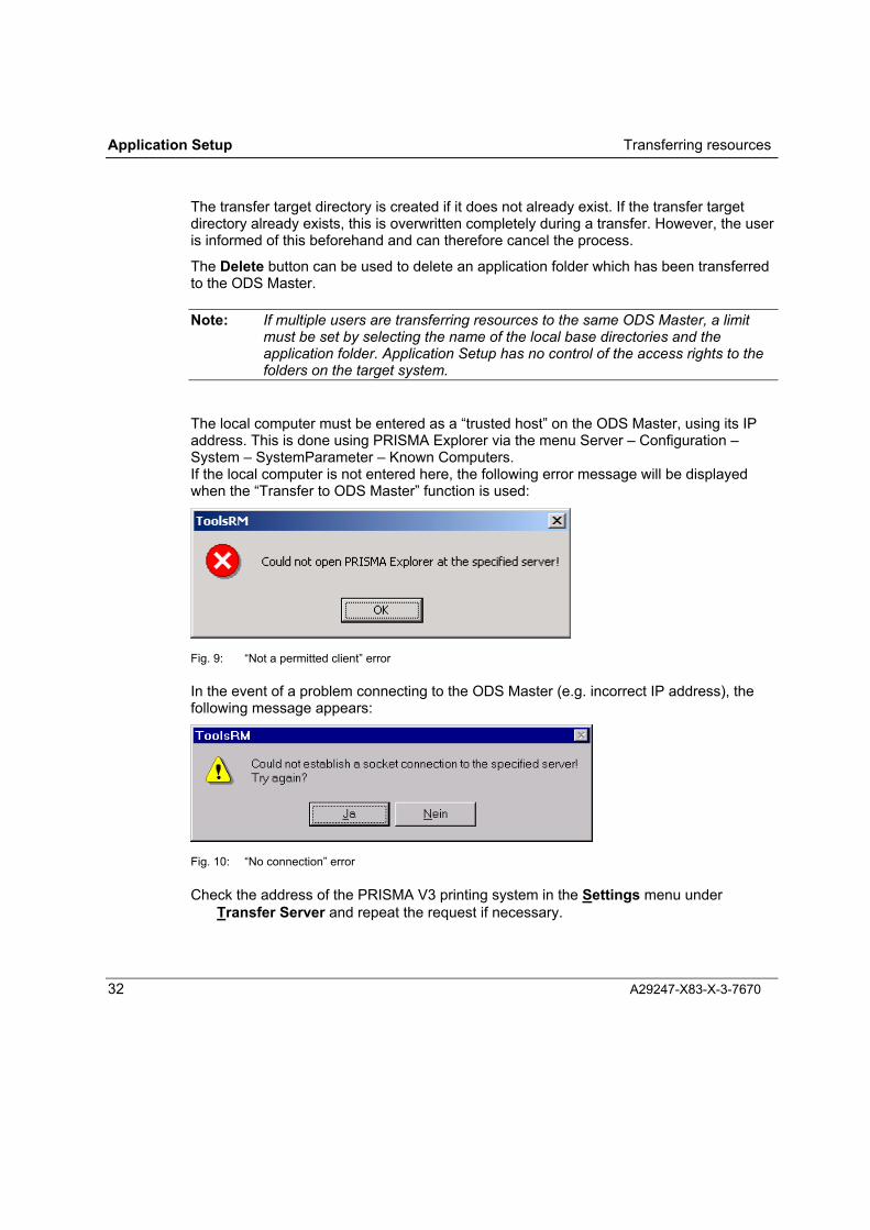
The transfer target directory is created if it does not already exist. If the transfer targetdirectory already exists, this is overwritten completely during a transfer. However, the useris informed of this beforehand and can therefore cancel the process.
The Delete button can be used to delete an application folder which has been transferredto the ODS Master.
Note: If multiple users are transferring resources to the same ODS Master, a limitmust be set by selecting the name of the local base directories and theapplication folder. Application Setup has no control of the access rights to thefolders on the target system.
The local computer must be entered as a �trusted host� on the ODS Master, using its IPaddress. This is done using PRISMA Explorer via the menu Server � Configuration �System � SystemParameter � Known Computers.If the local computer is not entered here, the following error message will be displayedwhen the �Transfer to ODS Master� function is used:
Fig. 9: �Not a permitted client� error
In the event of a problem connecting to the ODS Master (e.g. incorrect IP address), thefollowing message appears:
Fig. 10: �No connection� error
Check the address of the PRISMA V3 printing system in the Settings menu underTransfer Server and repeat the request if necessary.

Font Creation
A29247-X83-X-3-7670 33
FONTCREATION


Introduction Font Creation
A29247-X83-X-3-7670 35
Font Creation
Introduction
Outline Fonts
Mapping Editor
Bitmap fonts
OMSLIB
SPDS Outline
1 Byte / 2 Byte
PCL4Softfont
MOD2
LCDS
SPDS1 Byte / 2 Byte
FontCreation
InstalledWindows
Fonts
TrueTypeFonts
Type1Fonts
MappingTables
Fig. 11: Font Creation � a system overview
With the Font Creation program, you can create the fonts with which to producesophisticated documents on your Océ high performance printing system. You can createfonts from the fonts installed in Windows, from the TrueType fonts in TTF files, or fromType1 fonts in PFB files.
You can generate single-byte fonts (SBCS) for European type and the double-byte fonts(DBCS) necessary for Far East type.

Font Creation Introduction
36 A29247-X83-X-3-7670
With the mapping editor in Font Creation, you can
• Modify the mapping table and
• When working with bitmap fonts, combine characters of up to three different fonts inone printer font.
The fonts can be output in different formats for different printing systems.
Features
Font Creation is a GUI-based Windows application with menus and an integrated helpsystem.
Font Creation is installed as part of Océ PRISMAtools with the help of the InstallShield®
Assistant, which guides you through the setup.
Source Fonts
You can generate printer fonts from the fonts installed in Windows, from TrueType fonts inTTF files and from Type1 fonts in PFB files.
There is a range of type CDs available for Font Creation, with European and Far Eastfonts and linear bar codes. Font Creation program ships with one type CD of your choice,and you can also order additional ones if you wish. Each CD presents you with anextensive collection of fonts to choose from.
• European CD-ROM with euro currency sign(URW EuroWorks plus core fonts: CD-ROM with over 540 TrueType fonts)
• TrueType monospaced fonts with euro currency sign
• Chinese CD-ROM
• Japanese CD-ROM (NEC Fontavenue)
• Linear bar code CD-ROM
For example: in addition to the traditional text fonts, the URW EuroWorks CD-ROM alsocontains headline fonts and script fonts, as well as the Nimbus Sans and Nimbus Romanfont families commonly used on Océ high performance printing systems.
Font Creation generates its fonts from source (input) fonts that are either selected fromthe fonts installed in Windows or taken from TTF or PFB files.
You can use type CDs directly as your input media for generating fonts with FontCreation, but you can also install selected CD fonts in Windows and then select the fontsfrom the library on your system.

Introduction Font Creation
A29247-X83-X-3-7670 37
Note: To generate SPDS outline fonts, Font Creation needs direct access to therelevant font file.
To install TrueType fonts or Type1 fonts from the CD onto your system, use theWindows command Install New Font... from the File menu when the fonts folder is open.
Mapping Tables
A mapping table sets the code under which the printing system will find a particularcharacter.
Normally, you will use standard mappings for specific systems environments and forspecific languages (i.e. the special characters required by this language). Over a hundredmapping tables for very different operating conditions ship with the Font Creation softwarepackage.
With the mapping editor, you can edit mapping tables to suit your own requirements. Youcan change code assignments by simple drag-and-drop operations.
The characters for the mapping table can be selected from up to three source fonts.


Functions Font Creation
A29247-X83-X-1-7670 39
Overview of Font Creation Functions
Font Creation Functions
Font Creation generates fonts for Océ printing systems from installed Windows fonts orfrom font files. Depending on the selected output format, the printer fonts are generatedeither as bitmaps or as outline fonts. Each bitmap font can combine characters from up tothree different fonts, using a custom mapping table.
The fonts that Font Creation generates are described by
• The font header with information about the typeface and print formats,
• The type characters as bitmaps or outlines
and
• The code page (mapping table)
The fonts can be output in different formats for different printing systems.
Font Header
General information on the typeface, the print formats and on the output format of the fontfile can be saved in the font header. Font Creation derives this information from thesource font as far as possible. You can adapt the information in the font header bychanging entries in a dialog box, and you can also add additional information, again bymaking entries in a dialog box (see Chapter �Modifying the Font Header�).
Type Characters
Font Creation generates, from the input font, a font in which every character isrepresented as a bitmap pattern or outline. The font size is specified in pica points (p). Inthe case of bitmap fonts, the font size can be specified in millimetres or pixels instead ofpoints. In addition, you can specify various application-specific parameters. The procedurefor generating fonts is described in detail in Chapter 4.
Note: Fonts (bar codes, MICR fonts, etc.) created with Font Creation may in somecases deviate from usual industry standards. To prevent inconveniencecaused by non-compliance, extensive printing and reading tests should beconducted with the fonts before beginning productive operation.
Font Creation Functions
40 A29247-X83-X-3-7670
Mapping Table
In order to output printed data in a readable form, the type characters are assigned to thecoded characters via a code page � termed a mapping table in Font Creation. A mappingtable is structured in the form of a matrix, in which the combination of column number androw number defines the character coding.
Characters are coded in a single byte or in two bytes. Single-byte coding provides 256codes (hex 00 to FF), double-byte coding 65,536 codes (hex 00 00 to FF FF). Single-bytecoding is adequate for European type systems. Far East type systems such as Chinese,Japanese or Korean require double-byte coding.
With Font Creation, you can generate and modify both single-byte and double-bytemapping tables. The program ships with a wide range of common tables.
With the help of the mapping editor, you can:
• Display the tables in graphical form on the screen,
• Modify them according to your wishes
• Save modified tables under a new name.
You can also print the tables on your printer. Chapter 4.5 has a detailed description ofhow a mapping table can be edited with the Font Creation mapping editor.
Font Output Formats
The fonts can be generated in different formats for various printing systems (see Chapter:Font Output Formats). You specify the format as a parameter before the generation isstarted (see Chapter: Setting Parameters for Generating Fonts).
As far as the output formats are concerned, a distinction must always be made betweenbitmap fonts and outline fonts. Whereas in the case of bitmap fonts, every character isrepresented in the form of a fixed bitmap, outline characters are described in outline form,i.e. their outlines are drawn in the form of straight lines and curves.
Font Creation generates printer fonts in the following formats:
• MOD2 (E-MODE)
• SPDS (single and double-byte, relative metrics, fixed metrics), including LCDS triplets(SPDS-coded fonts) for PRISMA and LCDS
• SPDS outline (SBCS, DBCS, Big Endian Unicode)
• OMSLIB
• PCL4
• LCDS

Functions Font Creation
A29247-X83-X-3-7670 41
Unicode fonts
Font Creation permits the creation of SPDS Outline fonts for printing Unicode data with�Big Endian� coding. To do this, Font Creation provides the assignment Unicode(BE)internally.
As with all SPDS Outline fonts only one TrueType font file can be used here as the entryfont.
The internal assignment Unicode(BE) cannot be edited, but can be viewed.
When generating the SPDS Outline font, the complete code page (i.e. all Unicodes arereferenced) is always created with the fixed name T1UNICOD.This then has the same content for all Unicode fonts created using Font Creation. Thismeans that it doesn�t need to be generated each time, except when changing the outputformat or other parameters in the �Font header for fonts in the SPDS Outline format�.
Unicode Outline fonts can only be used in the layout process. Form Creation does notsupport double-byte printer fonts (and therefore no Unicode printer fonts, either).

Font Creation User Interface
42 A29247-X83-X-3-7670
Font Creation User InterfaceFont Creation is run from a graphical user interface . In the main window of FontCreation, you can input the specifications for generating the printer fonts and in themapping editor window, you can edit mapping tables (code pages). Specific dialogboxes can be opened for the various settings and default specifications.
Main Font Creation Window
Fig. 12: Main Font Creation window
The main Font Creation window is divided into four areas:
• Windows title bar
• Menu bar
• Input area
• Information bar
Title BarThe program name is given in the title bar. In addition � as is usual in Windowsapplications � there are the buttons for maximising or minimising the window and forclosing the program.
Input area
Title bar
Menu bar
Informationbar

User Interface Font Creation
A29247-X83-X-3-7670 43
Menu BarThe menus in the menu bar contain the commands that you do not need all the timeduring a program session. The following functions are available:
Print Character Overview Print an overview of characters in the selectedsource fonts.
Mapping Import Normal � Import a mapping table in the normal format(file: *.smt).
Import IKARUS ... Import a mapping table in IKARUS format (file*.bel).
Delete ... Delete installed mapping tables.
Type1 CharacterMapping4
Opens the "Type 1 Character to UnicodeMapping" dialog box.
TT Archive Use Archive Fonts Use additional archived TrueType fonts,when you want to combine characters fromseveral fonts in one printer font.
A ?? Only for bitmap fonts:Select and archive a second TrueType font.
B ?? Only for bitmap fonts:Select and archive a third TrueType font.
Configuration Output Format Select the output format for the generated font.
Measuring System Set the measuring system and resolution forthe generated font.
FilenameExtensions...
Open a dialog box in which you can specifythe file name extensions for SPDS (I mode),SPDS outline and LCDS output files. Fordetails about naming conventions, refer to therelevant section in Chapter 4.7.
Font Infobase ... Open the FontsInfobase window.
FontsInfobase is a program for automaticorganisation and administration of the fonts forLayout for AFP Line Data and FormCreation. The font information is incorporatedautomatically; there is no need to make entriesmanually. If FontsInfobase has not beeninstalled, the command is unavailable (grey).
FontsInfobase is installed automatically as partof the RSC V2 installation from the OcéPRISMAtools CD-ROM. RSC also provides

Font Creation User Interface
44 A29247-X83-X-3-7670
additional FontsInfobase functions to manage(browse, delete, add) the font database.
Language ... Open the "Choose Language� dialog box witha list of the languages available for the userinterface.
Code Page for CODFile ...
Open the "Choose code page for .COD� dialogbox.
If you intend to use the new fonts in FormCreation, you need to generate a COD file.From the COD file, Form Creation retrieves theinformation telling it which Windows fonts touse in order to match the on-screenpresentation to the appearance of the form asit will be printed.
Select the mapping that is suitable for theversion of Windows under which you run FormCreation.
If you check the option "Auto detect Symbolcharacter set", Font Creation will automaticallyassign the correct mapping when a symbol setis selected.
? Using Help Display online help.
Info... Display information about the installed FontCreation software.
Shift+Info displays the current Font Creationversion number.

User Interface Font Creation
A29247-X83-X-3-7670 45
Input Area
Fig. 13: Font Creation input area
The elements of the input area have the following functions:
1 Under "Font Type", choose whether the input font should be selected from theinstalled Windows fonts or from a file.
2 In the "Font Name� field, you can select an input font for the font generation (thebutton ... after the field opens the list of available typefaces or the dialog box forloading a TTF or PFB file).
3 In the "Mapping� field, you can select a mapping table (the list of available mappingtables is displayed by clicking the 6 button).
4 Click the Edit button to start the mapping editor.
5 The font definitions are listed in the �Printer Font(s)� field. Here, you can specifywhich fonts are to be generated, in what size and with which font header. During thegeneration, which you start by clicking the Do it! button, this list is processed inbatch mode.
6 Click the Add button to open the "Font Name for Printer" dialog box for defining orselecting a font name. When you confirm this dialog box, the name is added to thelist of the printer fonts to be generated.
7 Click the Delete button to delete the selected line from the list of fonts.
2 3
15
9 11
13
12
10
8
76
15
4
14
Font Creation User Interface
46 A29247-X83-X-3-7670
8 Click the Filename button to open the "Font Name for Printer" dialog box for theselected line in the list of fonts. You can use this dialog box to change the font name.In the list, the complete path under which the font should be saved is specified underFilename .
9 Click the Size button to change the font size specification. In the list under Size, youcan specify the character size of the font to be generated in the unit of measurementthat has been set (see the information bar).
10 You can use the arrow buttons to change the size specification in the selected line ofthe font list.
11 Click the Font Header button to open the dialog box for editing the font header. Thelist under the button indicates whether the font header will be generated directly fromthe input font (<default>), from a TTI file (<TTI>), or from user specifications(<user>).
12 Click the FontsInfobase box. If �FontsInfobase� is selected, the generated font willbe added to the font infobase automatically. The check box has no effect on creatingfiles for Form Creation and Layout for AFP Line Data. These files always will becreated and additionally stored in the output path of the character set.
13 Click the Do It button to begin generating the printer font with the default values thathave been set.
14 Click the Exit button to end Font Creation.
15 Click the Help button to invoke the Font Creation Help system.
Information BarThe following current parameters for generating fonts are displayed in the Informationbar:
• The unit of measure for specifying the size of the font to be generated
• The output format for the font to be generated
• The resolution of the printer for which a font is to be generated
These generation parameters are set using commands in the Configuration menu.

User Interface Font Creation
A29247-X83-X-3-7670 47
Font Creation Mapping Editor Window
Fig. 14: Font Creation mapping editor window
The mapping editor window consists of
• The code matrix with 256 fields
• The character box
• The buttons for selecting which of the current fonts should be displayed in thecharacter box: M = Selected font (Master),A = Archive font A (only available if bitmap fonts are to be generated)B = Archive font B (only available if bitmap fonts are to be generated)
• The Unicode monitor
• The field for selecting the Unicode range
Font Creation User Interface
48 A29247-X83-X-3-7670
• The section indicator for double-byte mapping
• Standard functions: OK, Cancel, Help
Code MatrixThe code matrix shows, in 16 rows and 16 columns, the characters that are available inthe selected typeface. The row and column numbers form the data code to which the fontcharacter in the corresponding position is assigned.
Character BoxThe characters that are available in the selected typeface are displayed in the characterbox. If archive fonts (A and/or B) have also been previously loaded for generating bitmapfonts, you can click the buttons at the top of the box to display the characters in thesefonts instead of the characters in the master.
The display in the character box can be scrolled with the help of the scroll bars on theright-hand border. By entering a Unicode number (4-digit, hexadecimal), you can alsoposition the pointer to a certain character.
Only 32,567 characters can be displayed under Windows 95; this is a restriction of theoperating system. For Far East fonts, which have many more characters, you can selectthe Unicode rages "CJK Unified� (Chinese/Japanese/Korean Unified) and Hangul todisplay all the characters defined in the Unicode in the character box.
Another key difference is that available characters are displayed depending on whether afile or an installed Windows font was selected.If the file is external, only the characters that are actually in the file are shown. If the fonthas been installed in Windows, a character is shown for every Unicode (e.g. fromUNICODE 0020 � FFFF). Unoccupied code points are represented with a small box.
Unicode MonitorThis field contains the Unicode of the character the mouse is pointing at in the mappingtable or character box.
When you make an entry in this field, the character box is automatically scrolled to thecharacter with the Unicode you have entered.
If this character is not included in the font, the character with the next-higher Unicode isdisplayed.
Field for Selecting Unicode Range (Area)Here you can select, for Asian fonts, whether the group of unified Chinese, Japanese andKorean fonts (selection "CJK Unified�, Unicode range 4E00-9FFF) or the group of Hangulcharacters (AC00-D7FF) should be displayed in the character box (see above).

User Interface Font Creation
A29247-X83-X-3-7670 49
Range IndicatorIn the case of double-byte mapping tables, this field shows which section or range of themapping is visible in the code matrix.
Vice versa, you can also enter a hexadecimal section number from 00 to FF to fetch acertain section into the matrix.
This field is not displayed when you display single-byte mapping tables.
Properties ButtonUse this button to open the "Properties" dialog box. This dialog box enables you to enteror change the name and identifier of a mapping table (see Chapter: Setting Properties).

Font Creation Working with Font Creation
50 A29247-X83-X-3-7670
Working with Font CreationIn order to generate fonts for Océ printing systems using Font Creation, you follow theprocedure outlined below:
⇒ Launch Font Creation.
⇒ Set parameters for generating fonts.The parameters you set are retained until you next change them. You only needmodify the parameters if you need to work with different settings.
⇒ Select a source font.In order to generate a printer font for an outline font, Font Creation needs a file withthe source font. If you are generating a printer font for a bitmap font, the source fontcan be either taken from an external file or be selected from the fonts installed on yoursystem. For generating bitmap fonts, you can also select two additional source fontsand declare these as archive fonts A and B.
⇒ If you are working with Type 1 fonts: Edit the mapping of the Type 1 characters toUnicode.
⇒ Select a mapping table (code page).You may also need to import a suitable mapping table .
⇒ Edit the mapping table, if you need modified character mapping or if you want tocombine characters from more than one source font in the font generated by FontCreation.
⇒ Define your generation list � i.e. add one or more font definitions.
⇒ Define the point size(s) of the fonts you want to generate
⇒ Define the file names of the fonts you want to generate.
⇒ Modify the font header information (if necessary).
⇒ Generate the font(s) for the Océ printing systems.

Working with Font Creation Font Creation
A29247-X83-X-3-7670 51
Launching Font Creation
The Font Creation program is launched either from the program folder created during theinstallation (Océ - PRISMAtools) or via the Windows menu Start / Program Files / Océ -PRISMAtools.
Setting Parameters for Generating Fonts
Before you can define the fonts you want to generate, you have to specify:
• The format in which the new fonts are to be generated
• The file name extensions you want to use for saving files for SPDS and LCDS formats,
• The measuring system in which you want to define font sizes
• The resolution of the printer on which the fonts will be used
Once you have defined the fonts, you cannot change these parameters. If you do changethe parameters after defining the fonts, the list of defined fonts is deleted.
The parameter settings are displayed on the information bar in the main Font Creationwindow.

Font Creation Working with Font Creation
52 A29247-X83-X-3-7670
4.2.1 Defining an Output Format
⇒ Choose Output Format from the Configuration menu. This opens the "OutputFormat" dialog box.
Fig. 15: Selecting an output format
⇒ Select the output format you want to use.
⇒ Click OK to confirm the dialog box.
⇒ After closing the "Output Format" dialog box, Font Creation automatically opens the"Measuring System" dialog box. Select the measuring system you want to use andenter the resolution of the printer for which you are generating the fonts (seeChapter:Setting Parameters for Generating Fonts).

Working with Font Creation Font Creation
A29247-X83-X-3-7670 53
4.2.2 Defining File Name ExtensionsThe conventions for naming output files are determined by the system on which thegenerated fonts will be used. In the "File Name Extensions" dialog box, you can specifywhich extension is to be appended to the names of output files for SPDS (I mode), SPDSoutline and LCDS formats. For all other output formats, the file name extensions arepredetermined.
You cannot make any changes to the settings in this dialog box if there are already entriespresent in the list of fonts to be generated (see Chapter:Assembling the List of Fonts toGenerate).
⇒ Choose Filename Extensions in the Configuration menu to open the followingdialog box:
Fig. 16: "Filename Extensions" dialog box
⇒ Select the tab for your output format and change the proposed extensions to suit therequirements of the destination system.Your selection for the case (Uppercase or Lowercase) applies to the entire filename.
− PRISMA: Lower case without file name extension
− Host: Upper case using proposed file name extensions*.CDF/ *.CDP/*.CHS for SPDS or *.FNT for LCDS.

Font Creation Working with Font Creation
54 A29247-X83-X-3-7670
4.2.3 Selecting a Measuring System
⇒ Click Measuring System in the Configuration menu to open the following dialogbox:
Fig. 17: Measuring System dialog box
⇒ Select the unit in which you want the size of fonts to be measured! Pica Point! mm! PixelIf you have selected SPDS outline as your output format, the unit is set to pica pointsand cannot be changed.
⇒ If you check the "H-Height" option, the list of fonts in the main Font Creation windowwill also show the height of the upper case H in the selected measuring unit.
⇒ Click OK to confirm the dialog box.
Note: The formula for converting the units is: 1 inch = 25.4 mm = 72 Pica Points.

Working with Font Creation Font Creation
A29247-X83-X-3-7670 55
4.2.4 Setting the Printer Resolution
⇒ Click Measuring System in the Configuration menu to open the "Measuring System"dialog box (see Chapter:Setting Parameters for Generating Fonts).
⇒ In this dialog box, enter the desired dpi value in the Printer Resolution box.
⇒ Click OK to confirm the dialog box.
4.2.5 Selecting a Code Page for COD FileIf you intend to use the new fonts in Form Creation, you need to generate a COD file.From the COD file, Form Creation retrieves the information telling it which Windows fontsto use in order to match the on-screen presentation to the appearance of the form as it willbe printed.
⇒ Click Choose Code Page for COD in the Configuration menu to open the followingdialog box:
Fig. 18: Selecting a code page for the COD file
⇒ Select the mapping that is suitable for the version of Windows under which you runForm Creation. An incorrect setting will cause text to be displayed incorrectly in FormCreation and to disappear from the generated form.
If you check the option "Auto detect Symbol character set", Font Creation willautomatically assign the correct mapping when a symbol set is selected.

Font Creation Working with Font Creation
56 A29247-X83-X-3-7670
Selecting a Source Font
4.3.1 Selecting an Installed FontIf you are generating bitmap fonts, you can use a font that you have installed in Windowsas your source or input font.
⇒ In the main Font Creation window, select "Installed Fonts" under "Typeface".
⇒ To load this font as the master font, click the � button in the "Font Name" field in thefont window.
⇒ To load this font as archive font A or B, choose Use Archive Fonts in the TT Archivemenu. Click A ?? or B?? to open a dialog box for archive A or B respectively.
⇒ From the list under "Typeface", select the name of the typeface you want to use.
⇒ Under "Style", select the desired font style (standard, italic, bold or bold italic.
⇒ Click OK to confirm these settings.The name of the master font will be displayed in the main Font Creation window andthe name of the archive fonts are shown in the TT Archive menu beside the A and Bcommands.
Loading a Font from a FileFont Creation can also use fonts that have not been installed in Windows. In fact, whenyou are generating an outline font, the source font must be in a TTF or PFB file.
Note: You can only use Type1 fonts from PFB files if you have ATM (Adobe TypeManager) installed on your PC.

Working with Font Creation Font Creation
A29247-X83-X-3-7670 57
To load a font from a file:
⇒ Under �Typeface�, select �TrueType file/Type1 file�.
⇒ To load this font as the master font, click the � button in the "Font Name" field. Thisopens the "Load Font" dialog box.
⇒ To load this font as archive font A or B, choose Use Archive Fonts in the TT Archivemenu. Choose A ?? or B?? in the TT Archive menu to open the "Load Font" dialogbox for archive A or B respectively.
⇒ In the "Load Font" dialog box, specify the path and file name from which the input fontis to be taken.
⇒ Click "Open" to confirm the selected font. The name of the master font will then bedisplayed in the main Font Creation window and the name of the archive fonts areshown in the TT Archive menu beside the A and B commands. B:
Fig. 19: Loading a font (here TrueType)

Font Creation Working with Font Creation
58 A29247-X83-X-3-7670
Fig. 20: Loading a font (here Type1)
Note: You can also order the type CD URW EuroWorks for the Océ PRISMAtools �this contains a wide collection of TrueType and Type1 fonts for just about anyapplication.
Master and Archive Fonts of Different TypesIf you want to use different type of fonts for the master and archive fonts � for example, aninstalled font for the master and a font from a file for the archive � you must select andassign the archive font(s) first, and then select and assign the master font.
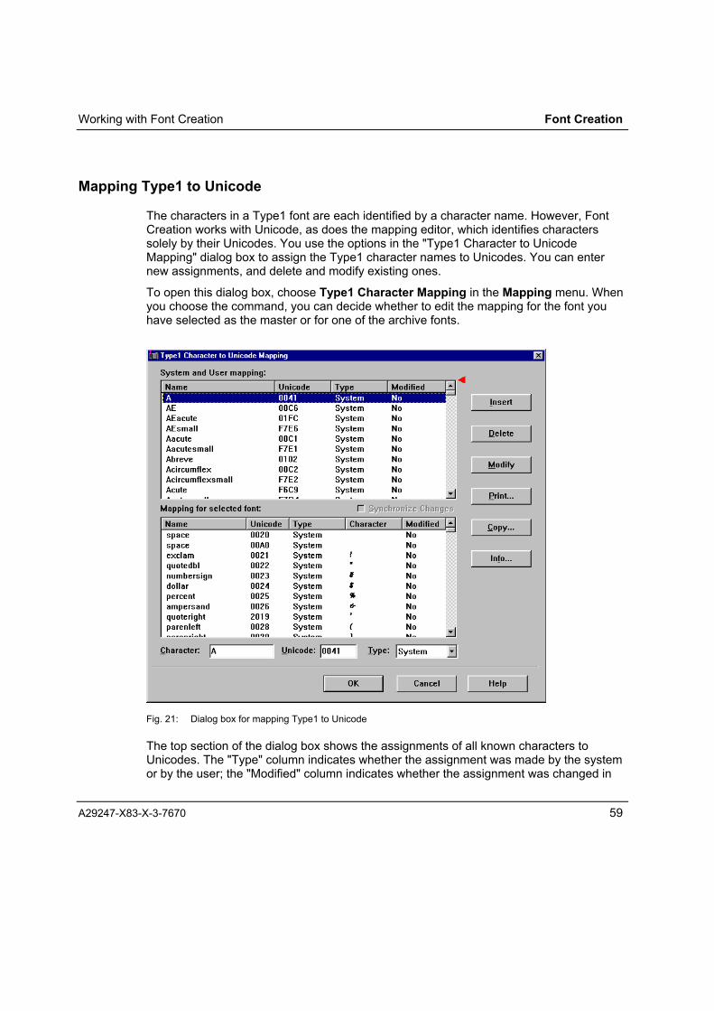
Working with Font Creation Font Creation
A29247-X83-X-3-7670 59
Mapping Type1 to Unicode
The characters in a Type1 font are each identified by a character name. However, FontCreation works with Unicode, as does the mapping editor, which identifies characterssolely by their Unicodes. You use the options in the "Type1 Character to UnicodeMapping" dialog box to assign the Type1 character names to Unicodes. You can enternew assignments, and delete and modify existing ones.
To open this dialog box, choose Type1 Character Mapping in the Mapping menu. Whenyou choose the command, you can decide whether to edit the mapping for the font youhave selected as the master or for one of the archive fonts.
Fig. 21: Dialog box for mapping Type1 to Unicode
The top section of the dialog box shows the assignments of all known characters toUnicodes. The "Type" column indicates whether the assignment was made by the systemor by the user; the "Modified" column indicates whether the assignment was changed in

Font Creation Working with Font Creation
60 A29247-X83-X-3-7670
the current editing process or not. The dialog box contains only this section � and nobottom section � until you load a Type1 font.
If you loaded a Type1 font before opening the dialog box, you will see an additionalsection at the bottom of the dialog box stating the assignments of the character names inthis font to the Unicodes. This section also shows the character that the name andUnicode represent.
You can alter the way in which the list entries are sorted. Click any of the columnheadings � Name, Unicode, Type or Modified � to sort the list according to this criterion.When you first click the column heading, entries are sorted top-down; a second click onthe same heading sorts the entries bottom-up.
Beneath the list are the fields for editing the character, Unicode and type. You can enternew definitions for the general assignment list and make changes for the table belongingto the font that is currently loaded. To change an existing definition, select thecorresponding line in the list. The details for this line then appear in the edit fields belowthe list.
Edit field Content
Character You can only define new character names for the general mapping list.The list belonging to the font which is currently loaded contains only thenames of the characters which are actually available � you cannotchange these entries.
Unicode Use this field to assign a different Unicode to a character name. You areprevented from entering an invalid code.
You cannot change system-defined mappings in the general mappinglist. If you do change a system definition, you have to add it to the list asa new, user-defined mapping, leaving the original one unchanged. Youcan change the user-defined mappings in the general list also.
Type There are three types of definition in the mapping tables: System, Userand Temporary. In the Type field, you can choose between "System" and"User". "Temporary" appears only if the program encounters a characterin a preloaded font that is not present in the general mapping list. In thisevent a temporary mapping is entered. You can change the "Temporary"setting to "User".
If you change the name or code of a system definition, the "Type" field automaticallychanges to "User" to indicate that this is now a user definition. For the font that is loaded,you can make a system definition into a user definition, but you cannot make a userdefinition into a system definition. You cannot change the "System" type in the generalmapping list. You can only add more definitions (i.e. user definitions) to those alreadypresent.

Working with Font Creation Font Creation
A29247-X83-X-3-7670 61
The buttons in this dialog box have the following functions:Button Function
Insert The entries in the edit fields are placed as an additional definition in thecurrent list (red wedge).
Delete Click this button to delete a selected entry from the list. You can onlydelete user-defined entries from the general list.
Modify The entries in the edit fields overwrite the original definition in themapping list. You can only modify user-defined entries in the generallist.
Print� Click this button to print the current mapping list (indicated by the redwedge). The printout is in tabular format.
Copy... Copies the mappings in the current list (indicated by the red wedge) tothe clipboard in the form <code>=<name>.
Info... Opens a message window displaying the following details about thegeneral mapping table and the mapping table of the selected font:- Number of system-defined entries,- Number of user-defined entries,- Number of new entries,- Number of deleted entries,- Number of modified entries.
OK Saves the changes and closes the dialog box.
Cancel Discards changes to the mapping lists and closes the dialog box. If youhave made changes to the list, you will be asked if you want to savethem.
Help Displays online help about this dialog box.

Font Creation Working with Font Creation
62 A29247-X83-X-3-7670
If you check the Synchronise changes option, all changes you make to the mapping listsfor the current font are also integrated into the general mapping list. For instance, if youedit or delete a user-defined mapping which if present in both tables, the change isimplemented in the general list as well.
Note: Font Creation gives a user-defined mapping priority over a system-definedmapping. In other words, if a character is defined twice � once with a systemmapping and once with a user-defined mapping � Font Creation uses thecharacter with the code assigned by the user.
Selecting a Mapping Table
Selecting Installed Mapping Tables
⇒ Click the arrow button 6 beside the Mapping field to open the list of availablemapping tables. The list contains only mapping tables that have been copied to theFont Creation folder as SMT files. The list shows the names of the tables, not filenames. Global ASCII and double-byte mappings are defined in Font Creation, andthese are available for selecting from the list. You can import additional mappings(see below).You can also import mappings in IKARUS format (see below).
Fig. 22: Selecting a mapping table

Working with Font Creation Font Creation
A29247-X83-X-3-7670 63
⇒ Select the mapping table you want to use. This table becomes the current mappingtable and its name is shown in the "Mapping" field in the main Font Creation window.
If your list of fonts to be generated includes a font that uses a different mapping table, amessage is displayed to remind you that the parameters will be changed:
Fig. 23: New mapping message
Importing a Mapping Table from an SMT File (Normal)
⇒ Choose Import Normal from the Mapping menu in the main Font Creation window.This opens the "Import Mapping" dialog box for importing normal mapping tables.
Fig. 24: Dialog box for importing mapping

Font Creation Working with Font Creation
64 A29247-X83-X-3-7670
⇒ From the "Drives" list, choose the drive from which you want to import the mapping;alternatively, click the Network... button to open the "Map Network Drive" dialog boxand map a network folder to a drive number.
⇒ From the "Folders" list, choose the folder from which you want to import the mappingtable.
⇒ The �List of mappings� field shows the table names (not file names) of all the SMTfiles in the selected folder.
⇒ Select the mapping table you want to import. You can also import all the listedmapping tables by clicking the Select All button.
⇒ Click OK to start the import.
Note: If you select the Font Creation installation folder, the import attempt is rejectedwith an error message, because the mapping tables in this folder have alreadybeen imported.

Working with Font Creation Font Creation
A29247-X83-X-3-7670 65
Importing Mapping Tables from BEL Files (IKARUS)
⇒ Choose Import IKARUS from the Mapping menu in the main Font Creation window.This opens the "Import Mapping" dialog box for importing IKARUS mapping tables.
Fig. 25: "Import Mapping" dialog box for IKARUS BEL files
⇒ In the "Files of type" list, select "IKARUS Mapping" (click 6 to display the list).
⇒ The entry "*.bel" is entered in the "Filename" field. From the �Look in� list, choose thedrive and folder from which the mapping table is to be imported. The list shows the filenames (not table names) of all the BEL files in the selected folder.
⇒ Select the file(s) you want to import, and click Open to start the import.
The imported mapping table will be placed in an SMT file. The name of the new mappingis derived from the name of the BEL file from which the mapping is imported, preceded by"IKARUS�. Example: the table imported from the file "Bar180e.bel� will be saved as themapping IKARUS-Bar180e and can be selected by way of this name from the "Mapping"pick list.

Font Creation Editing Mapping Tables
66 A29247-X83-X-3-7670
Editing Mapping Tables
Mapping tables can be edited with the mapping editor. You can change the charactermapping and add characters from two additional source fonts, assigned to archives A andB.
Opening the Mapping Editor Window
⇒ Click the Edit button beside the name of the mapping table to open the mappingeditor.
Fig. 26: Mapping editor

Editing Mapping Tables Font Creation
A29247-X83-X-3-7670 67
Displaying the FontThe character box to the right of the mapping matrix shows which characters areavailable in the font you have selected.
⇒ Click one of the buttons M, A or B to select which font to display (seechapter:Selecting a Source Font).
M the font selected as the master font
A = The font selected for archive A (available only for bitmap fonts)
B = The font selected for archive B (available only for bitmap fonts)
Note: Under Windows 95, a maximum of 32,764 characters can be displayed.
Positioning Characters in the Mapping Matrix
⇒ You can place characters in the matrix by dragging them from the character box.Unoccupied positions are marked with a .
Removing Characters from the Mapping Matrix
⇒ To remove a character from the matrix, click it with the right mouse button.
Assigning Characters from an Archive Font
⇒ Click the appropriate button (A or B) to select archive A or B.
⇒ Click the desired field in the mapping matrix with the left mouse button. If a characterwith the Unicode of this field is present in the archive font, this character is retrievedfrom the archive font and placed at this position.
Characters you have retrieved from archive fonts are shown in colour in the mappingmatrix.

Font Creation Editing Mapping Tables
68 A29247-X83-X-3-7670
Setting Properties
⇒ Click the Properties button to open the "Properties" dialog box. This dialog boxenables you to enter or change the name and identifier of a mapping table.
Fig. 27: "Save Mapping" dialog box
Use the "Save Mapping" dialog box to make the following settings:
Mapping: The name that Font Creation uses to address this mappingtable. This is the name you use to select the mapping. If youchange this name, the mapping table you have been editing willbe saved under the new name. The original mapping is retainedunder the old name.
If you do not change the name, the original mapping table will beoverwritten.
SPDS Code Page: Unique portion of code page file name for SPDS fonts. Thename of the code page file has the prefix T1 (Example: WIN310results in the file name T1WIN310.CDP).
SPDS CPGID: Code page global identifier; the identifier of the mapping table
SPDS GCSGID: Graphic character set global identifier

Editing Mapping Tables Font Creation
A29247-X83-X-3-7670 69
ISO No.: The ISO identification number. This field remains blank if there isno ISO equivalent for this mapping.
PCL Symbol Set ID: A character-digit combination as an identification for PCLprinters.
COD: Name of the COD file required by Form Creation and Layout forAFP Line Data.The COD file name must be an alphanumeric string. All specialcharacters are automatically replaced by the character '_� . Ifnecessary, the name is truncated to eight characters.
Version: Version number
Author: Name of the author.
Mapping Group Specify whether your mapping has ASCII or EBCDIC coding(ASCII: blank on 0x20, EBCDIC: blank on 0x40), otherwisechoose the "Custom" option.
⇒ Click OK to save the mapping table under the specified name and with the specifiedproperties.
Saving the Mapping Table
⇒ Click OK to close the mapping editor window.
• If you have made changes to the mapping, you will be prompted to save your changes.
⇒ If you click Yes in the prompt box, Font Creation opens the "Save Mapping" dialogbox.
⇒ In this dialog box, enter the name and properties with which you want to save themapping (see Chapter: Setting Properties). If you do not change the name, theoriginal mapping table will be overwritten.

Font Creation Assembling a List of Fonts to Generate
70 A29247-X83-X-3-7670
Assembling the List of Fonts to Generate
After you have chosen a source font (or two or three source fonts) and a mapping table,you can define the list of the fonts you want to generate. This list is created in the mainFont Creation window. In a single operation, you can generate up to 19 printer fonts withthe same typeface and mapping but with different sizes and individually modified fontheaders.
You must make at least one entry in the generation list before you can start a batchprocess for generating the printer fonts.
⇒ Click the Add button.This opens the �Name of Printer Font� dialog box, where you can specify the file type,file name and the folder of the printer font you want to generate. The list in the dialogbox shows existing printer fonts of the selected file type in the selected folder. The listin the dialog box shows existing printer fonts of the selected file type in the selectedfolder.
⇒ Select the type of file you want to generate. Click the 6 button next to the "Files oftype" field to display the list.
⇒ Enter the file name under which you want to save the printer font.
Different conventions must be observed for each file format.
File type Naming conventions forprinter fonts
SPDS (I-MODE) X0*.cdf
SPDS Outline xz*.cdf
LCDS *.fnt
MOD2 (E-MODE) *.ifn
OMSLIB mxm????
PCL4 *.sfp
In place of the asterisk, enter as manycharacters or digits as you need to makeup the name (without the extension) toeight characters.
You must enter one alpha character inplace of each query mark (?).
In the "Filename Extensions" dialog box, you can specify which extension is to beappended to the names of output files for SPDS (I mode), SPDS outline and LCDSformats. For all other output formats, the name extensions are predetermined (seeChapter: Setting Parameters for Generating Fonts).
⇒ When there are already fonts defined in the list in the main Font Creation window,Font Creation proposes the last name in this list as the name of the new font, with thelast digit or character in the name incremented by one.
⇒ In the "Save in" field, choose the folder to which you want to save the new printer font.

Assembling a List of Fonts to Generate Font Creation
A29247-X83-X-3-7670 71
⇒ Click the Save button to confirm and close the dialog box. A new font definition line isadded to the "Printer Font(s)" list in the main Font Creation window. The font in thefirst definition line is assigned the point size 8, and the size is incremented by onepoint with each entry you make. The font header is set to <default>.You can change the file name, font size and font header details afterwards (seeChapter: Assembling the List of Fonts to Generate and following).
⇒ To remove a definition line from the list, select it and click the Delete button.
⇒ Use the checkbox �FontsInfobase� in front of each line of the list to control whether thegenerated font should be added to the FontsInfobase or not. If this box is checked thegenerated font will be added to the FontsInfobase automatically.

Font Creation Defining the Font Size
72 A29247-X83-X-3-7670
Defining the Font Size
When you define a printer font, Font Creation assigns a default font size in the selectedmeasuring unit. The font in the first definition line is assigned the point size 8 points/2.00mm/20 pixels, and the size is incremented by one unit with each entry you make. You setthe measuring unit with the Measuring System command in the Configuration menu(see Chapter: Setting Parameters for Generating Fonts).
You can change the font size in a font definition as follows:
⇒ In the list in the main Font Creation window, select the line for the font whose size youwant to change.
⇒ Change the font size with the four arrows under the list: 5increases the font size, 6 decreases it. Use the left buttonsto change the digit before the decimal point. Use the rightbuttons to change the digit after the decimal point.
⇒ If you are using points or mm as your measuring unit, you can select the font sizesfrom a predefined list. Click the Size button to open a list of font sizes.
Fig. 28: Font sizes

Defining Font File Names Font Creation
A29247-X83-X-3-7670 73
Defining Font File Names
When you add a printer font definition to the generation list, you have to give a nameunder which the font is to be saved. Different naming conventions must be observed forthe various output formats (see Chapter:Assembling the List of Fonts to Generate). Youcan change the font name if you wish, provided you adhere to the naming conventions.
To define a new font name:
⇒ Click the Font Name button. This opens the �Name of Printer Font� dialog box:
Fig. 29: "Name of Printer Font" dialog box
⇒ In the "File name" field, enter the new file name for the font. The name must complywith the conventions for the selected output format (see Chapter:Assembling the Listof Fonts to Generate).
⇒ Click Save to confirm the new name and close the dialog box.

Font Creation Modifying the Font Header
74 A29247-X83-X-3-7670
Modifying the Font Header
Every font generated with Font Creation includes additional information that the printingsystem needs to represent the font. This information, which is stored in the font header,differs depending on the font output format, i.e. the font headers for each format containdifferent types of information.
Where possible, Font Creation extracts the additional information from the source font,and adds the resulting font header to the font as a default header. However, not all fontheader information can be derived in this way. Font Creation therefore derives theinformation from a TTI file (file name *TTI) assigned to the font. If Font Creation detectsthat there is a TTI file assigned to a font, it automatically extracts the information from thisfile.
Provided you observe the constraints of the output format, you can change the fontheader information in order to customise the file and font names and to change theappearance of the font.
To modify a font header:
⇒ In the list in the main Font Creation window, select the font whose header you want tochange.
⇒ Click the Font Header button above the list. This opens the "Font Header" dialog boxfor the set output format.
The preset parameters are shown in input fields in the dialog box.
The following sections explain the fields of the dialog boxes in detail.

Modifying the Font Header Font Creation
A29247-X83-X-3-7670 75
Font Header for SPDS Fonts (I-MODE)
Fig. 30: SPDS Font Header
Field Content
Font Name Name of the font
Code Page Name of the code page file (T1xxxxxx.CDP).
Code PageDescription
Comment describing the code page.
Point Size Size of the font in pica points.
The only way to enter the point size is by using the buttons in themain Font Creation window (see also "Entering the Point Size"below).
Line Spacing Distance between consecutive baselines in pixels.
Weight Ratio between toned and untoned areas within the character box.

Font Creation Modifying the Font Header
76 A29247-X83-X-3-7670
Field Content
Density Width-to-height ratio of a character
Encoding Code group assignment EBCDIC (Blank = X�40�), ASCII (Blank =X�20�) or custom.
EncodingCustomize
Settings for custom encoding:Default character: this is the character which is printed when areferenced code point has no correspond glyph in the font. Given inUnicode.Variable Space Character - Code Point: this character will not beprinted out. Instead the print position will be shifted by the value ofthe increment of this character, so that a space is printed.Variable Space Character - Increment Reference: the incrementvalue of the given Unicode character will be used as the incrementvalue of the variable space character.
Style The setting here has no influence on the look-and-feel of the printerfonts; it affects only entries in the structured fields. This setting isused if attributes cannot be extracted from the TrueType fonts by theprogram in the usual way.
Output Specify the output format of the font file. Use TRANS format for PC" host file transfers, because the format contains printablecharacters only. Use binary format for PC " PRISMA file transfers.
A,C Space forRotation 90,270
The values of the A and C space for rotations 90° and 270° can becalculated in more than one way, yielding different print results.1. Uniform increment: The sum of the A, B and C spaces is the samefor all the characters in the font.The following holds: A + B + C = max Asc0 + max Des0 = Increment0This setting is particularly important for printing texts.Relative to Height: A and C values are the same for all characters.The value is a fixed percentage of the heights.A = C = p * (max Asc + max Des)/100
Note: the A and C space values for 0° and 180° are derived directlyfrom the input font.Here: A180 = C0, C180 = A0

Modifying the Font Header Font Creation
A29247-X83-X-3-7670 77
Field Content
Miscellaneous Use Old Output Format: Font Creation generates a font in theformat of Siefont Version 1.24. This option is only possible for single-byte fonts.Big Character Set: Font Creation creates an output font containingall the characters of the source font, and not just those assigned inthe mapping.Data Check: Causes non-printing characters to be flagged by theprinting system. The printing system (e.g. PRISMA) makes an entryin the print log if a non-printing character is encountered.The "Data Check" option is entered in the code page, which makes itvalid for all fonts that use this code page.MICR: (Magnetic Ink Character Recognition). Check this option ifyou want to use the font in MICR applications.Relative Metrics: The printer fonts will be generated according tothe Relative Metrics specifications. The sizes are specified in relativeunits. The reference size is the height of the bounding box. Relativemetrics fonts should be generated for 300 and 600 dpi. An exceptionis the APA-2 controller, which only supports 300 dpi fixed metricsfonts.Original Point Size: The point size set by you or another user in themain window cannot always be generated with total precision. Thesmallest printable unit is a dot, or pixel. It is not possible to print half-dots. If, say, you choose point size 8 at 300 dpi, the point size will be7.92. Font Creation rounds this to 7.9.If you do not check this option, the real size calculated by FontCreation will be entered in the generated font (in the FND structuredfield).However, if you do check the option, the value you entered in FontCreation will be entered in the generated font. This option wasintroduced for DCF (SCRIPT/VS) due to this product's inability tomanage font sizes with decimal places (e.g. 7.9).Internally, Font Creation calculates the metrics of relative metricfonts according to the value entered in the FND structured field.However, the character sizes are always calculated according to thereal size determined by Font Creation.1. First Uniform Section: The section indicator for double-bytemapping (hex code). In the case of double-byte fonts, it is importantthat the individual characters are a fixed distance apart.Unfortunately, not all TTF fonts conform. Font Creation can go someway to correcting this. In this field, you specify the section at whichFont Creation is to begin adjusting the character increments. If youdo not want Font Creation to attempt any adjustment, enter 0x100.

Font Creation Modifying the Font Header
78 A29247-X83-X-3-7670
Field Content
LCDS Triplets Generates SPDS-coded fonts for PRISMA+LCDS with theorientations Landscape, Portrait, Inverse Landscape and InversePortrait. Choose "-" to create standard SPDS-coded fonts.

Modifying the Font Header Font Creation
A29247-X83-X-3-7670 79
Font Header for Fonts in SPDS Outline Format
Fig. 31: SPDS outline font header
Field Content
Font Name Name of the font
Code Page T1 Name of the code page file (T1*.CDP).
Code PageDescription
Comment describing the code page
Default Point Size The point size at which the font is to be printed if no size is givenwhen the font is selected.
Line Spacing Distance between consecutive baselines in pixels. Font Creationenters a value equal to double the height of the character H.
Weight Ratio between toned and untoned areas within the character box.
Density Width-to-height ratio of a character

Font Creation Modifying the Font Header
80 A29247-X83-X-3-7670
Field Content
Style Italic, underlined and "MICR Ink Character Recognition�.
Mapping Code group assignment EBCDIC (Blank = X�40�) or ASCII (Blank= X�20�).
Output Specify the output format of the font file. Use TRANS format forPC " host file transfers, because the format contains printablecharacters only. Use binary format for PC " PRISMA filetransfers.
Miscellaneous MICR: (Magnetic Ink Character Recognition). Check this option ifyou want to use the font in MICR applications.Data Check: Causes non-printing characters to be flagged bythe printing system. The printing system (e.g. PRISMA) makes anentry in the print log if a non-printing character is encountered.Big Character Set: Font Creation creates an output fontcontaining all the characters of the source font, and not just thoseassigned in the mapping.
A,C Space forRotation 90,270
Settings required for double-byte fonts (e.g. Chinese).Uniform Increment: The sum of the A, B and C spaces is thesame for all the characters in the font (required for verticalprinting, e.g. Chinese, see Glossary).
Relative to Height: A and C values are the same for allcharacters. The default is 5 %.
Sort Order ofCode Page Index
Sort order for the output fontsDefault: the output is in ascending code point order for double-byte and in ascending character ID order for single-byte fonts.Code Point: in ascending order of code point.Graphic Character Global ID: in ascending order of characterID.
Global Identifiers Code Page Global ID: An identification number for the codepageGraphic Character Set Global ID: An identification number forthe code page for the graphical character setFont Global ID: An identification number for the font

Modifying the Font Header Font Creation
A29247-X83-X-3-7670 81
Font Header for Fonts in LCDS Format
Fig. 32: LCDS font header
Field Content
Font Type Specify the print direction here:Landscape: normal print directionInverse Landscape: normal print direction rotated by 180°Portrait: print direction rotated by 90°Inverse Portrait: 270° rotated
Line Spacing Distance between consecutive baselines in pixels. Font Creationenters a value equal to double the height of the character H.
Name of FGL-COD Name of the COD file required for Form Creation and Layout forAFP Line Data.
Average CharacterWidth
Average value of the character width in pixels.
Generate LabelBlock
A label block is a 128-byte header in a Xerox resource file. Itprovides information about the resource. One item of information,for instance, is the name of the resource (so take care whenrenaming resources).No label block is necessary if the fonts are to be used inPRISMA+LCDS.
A label block is absolutely essential if the fonts are to be used onXerox printing systems (Xerox format floppy disk). The labelblock can also be generated later by way of a utility such asXERDISK, which formats and writes to a Xerox-format floppy.

Font Creation Modifying the Font Header
82 A29247-X83-X-3-7670
Font Header for Fonts in MOD2 (E-MODE) Format
Fig. 33: MOD2 font header
Field Content
Line Spacing The number of lines that can be printed per inch using this font. As arule, you should set Auto here, since OFM will then compute thecorrect value automatically. If you do enter a particular line spacing,OFM checks whether the characters can really be printed using thisspacing. OFM issues a message if you set a line spacing that is toosmall for the font's size.
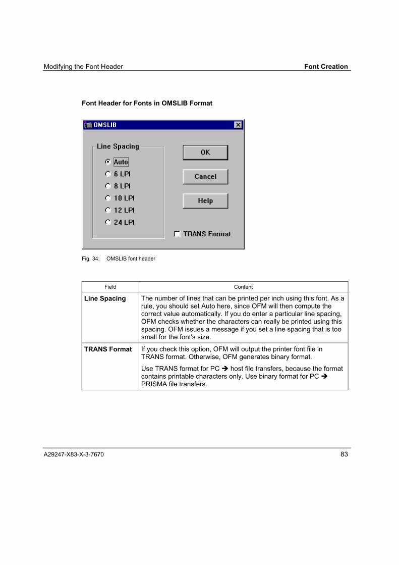
Modifying the Font Header Font Creation
A29247-X83-X-3-7670 83
Font Header for Fonts in OMSLIB Format
Fig. 34: OMSLIB font header
Field Content
Line Spacing The number of lines that can be printed per inch using this font. As arule, you should set Auto here, since OFM will then compute thecorrect value automatically. If you do enter a particular line spacing,OFM checks whether the characters can really be printed using thisspacing. OFM issues a message if you set a line spacing that is toosmall for the font's size.
TRANS Format If you check this option, OFM will output the printer font file inTRANS format. Otherwise, OFM generates binary format.
Use TRANS format for PC " host file transfers, because the formatcontains printable characters only. Use binary format for PC "PRISMA file transfers.
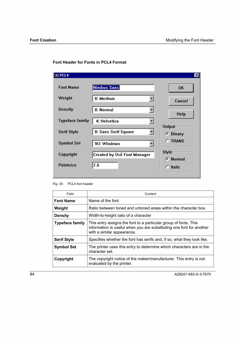
Font Creation Modifying the Font Header
84 A29247-X83-X-3-7670
Font Header for Fonts in PCL4 Format
Fig. 35: PCL4 font header
Field Content
Font Name Name of the font
Weight Ratio between toned and untoned areas within the character box.
Density Width-to-height ratio of a character
Typeface family This entry assigns the font to a particular group of fonts. Thisinformation is useful when you are substituting one font for anotherwith a similar appearance.
Serif Style Specifies whether the font has serifs and, if so, what they look like.
Symbol Set The printer uses this entry to determine which characters are in thecharacter set.
Copyright The copyright notice of the maker/manufacturer. This entry is notevaluated by the printer.

Modifying the Font Header Font Creation
A29247-X83-X-3-7670 85
Field Content
Point Size Size of the font in pica points.
Output Binary: Output in binary format
Trans: Output in TRANS format
Use TRANS format for PC " host file transfers, because the formatcontains printable characters only. Use binary format for PC "PRISMA file transfers.
Style Specifies whether or not the font is italic.

Font Creation Generating Fonts
86 A29247-X83-X-3-7670
Generating Fonts
Once you have defined at least one font in the main Font Creation window, you can:
⇒ Click the Do it! button to begin the generation process.
Font Creation generates one or more files for each font you have defined, depending onthe output format you have selected.
Generated filesOutput format
Font file Additional information
SPDS C0*.CHS (Character Set)X0*.CDF (Coded Font)T1*.CDP (Code Page)
X0*.INF*.COD*.CD2
SPDS outline C0*.CHS (Character Set)X0*.CDF (Coded font)T1*.CDP (Code Page)
XZ*.INF*.COD*.CD2
LCDS *.FNT (Printer font) *.INF*.COD*.CD2
MOD2 GRF2*A (Printer font, part 1)GRF2*B (Printer font, part 2)GRF2*C (Printer font, part 3)GRF2*D (Printer font, part 4)XTB1*A (Mapping)
*.LOG (Log file)
OMSLIB CAT* (Mapping)MXM* (Printer font)
*.LOG (Log file)
The files are generated with the name and in the folder you specified when you added thefont to the font generation list (see Chapter:Assembling the List of Fonts to Generate).
The internal additional information files are also located here.
If the �FontInfobase� checkbox in the font generation list has been marked for the fonts tobe generated, the fonts selected will be automatically included in the FontsInfobase whenon generation.
The current contents can be checked once the generation process has been started usingDo it!, by using the FontsInfobase... function in the Configuration menu (see Fig. 34).

Generating Fonts Font Creation
A29247-X83-X-3-7670 87
Fig. 36: Choosing folders
More information on this window can be found in the section FontsInfobase Browser onFont Import.
Please bear in mind that the output format and the resolution need to be set in this dialogaccording to the parameter in the font generation process.
Note: Fonts (bar codes, MICR fonts, etc.) created with Font Creation may in somecases deviate from accepted industry standards. To prevent inconveniencecaused by non-compliance, extensive printing and reading tests should beconducted with the fonts before beginning productive operation.

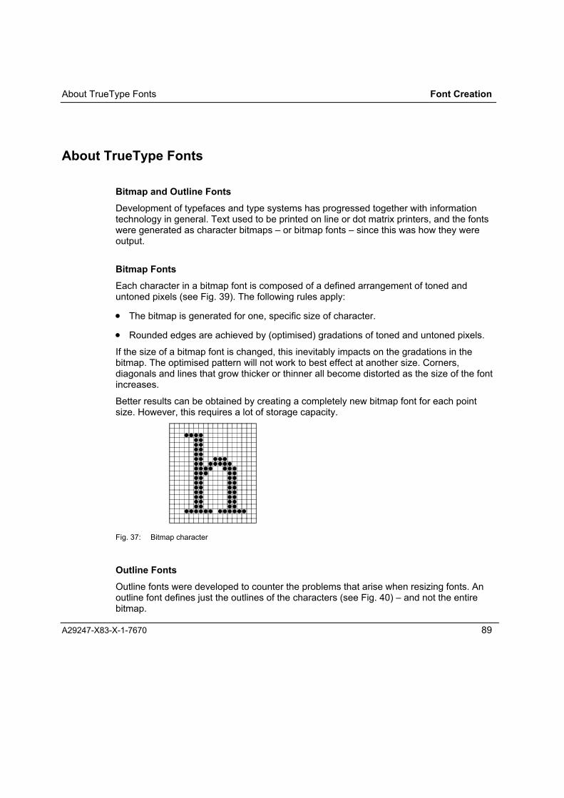
About TrueType Fonts Font Creation
A29247-X83-X-1-7670 89
About TrueType Fonts
Bitmap and Outline FontsDevelopment of typefaces and type systems has progressed together with informationtechnology in general. Text used to be printed on line or dot matrix printers, and the fontswere generated as character bitmaps � or bitmap fonts � since this was how they wereoutput.
Bitmap FontsEach character in a bitmap font is composed of a defined arrangement of toned anduntoned pixels (see Fig. 39). The following rules apply:
• The bitmap is generated for one, specific size of character.
• Rounded edges are achieved by (optimised) gradations of toned and untoned pixels.
If the size of a bitmap font is changed, this inevitably impacts on the gradations in thebitmap. The optimised pattern will not work to best effect at another size. Corners,diagonals and lines that grow thicker or thinner all become distorted as the size of the fontincreases.
Better results can be obtained by creating a completely new bitmap font for each pointsize. However, this requires a lot of storage capacity.
Fig. 37: Bitmap character
Outline FontsOutline fonts were developed to counter the problems that arise when resizing fonts. Anoutline font defines just the outlines of the characters (see Fig. 40) � and not the entirebitmap.

Font Creation About TrueType Fonts
90 A29247-X83-X-3-7670
The shape is defined by a series of closed outlines. Simple characters can be defined bya single outline, complex characters need two or more:
L = one outlinee = two outlinesB = three outlines
An outline consists of straights and curves. These are defined by a series of pointsdescribing a second-degree Bézier curve. The points are numbered consecutively.Whether the series is ascending or descending is essential for determining how theoutline is filled. When the points are traced in ascending order, the area to be filled is onthe right.
To create printable characters from an outline font, we first define the size of the font andthe resolution of the bitmap. The outline is then "placed" on a virtual grid of pixels andfilled with toned pixels.
Fig. 38: Outline character
HintingAlthough the character outlines are key to the quality of the printed characters, anotherfactor also plays a role: hinting. Hints are additional information on how the charactershould be represented. Particularly at resolutions up to 600 dpi, hints can greatly improvethe text output quality.
Structure of a TrueType FontA TrueType font file contains a full definition of the font. Each font consists of severaltables which contain information on character coding, metrics or operating-system-specificdata.
TrueType on Different Platforms

About TrueType Fonts Font Creation
A29247-X83-X-3-7670 91
The TrueType specification allows the format to be used on various computing platforms �although this does not imply that the same TrueType font can be used on multipleplatforms.
• Some of the tables in the font contain information specific to a particular OS, e.g.Windows or OS/2.
• Different platforms work with different character coding (e.g. 8 bit, 16 bit, 32 bit).
A.5 Advantages and Disadvantages of TrueTypeMicrosoft Windows version 3.1 made TrueType fonts part of the standard Windowsconfiguration. The fonts can be used both for screen and printer output. The mainadvantages are:
• Small files
• Good scalability
• Good output quality, even with high resolution rasters (the higher the resolution, thebetter rounded edges can be filled).
The obvious disadvantages are:
• More computing power is required for rasterizing
• Poor output quality at small point sizes.
Note: At small point sizes, machine-rasterized fonts can never achieve the samequality as bitmap fonts that have been designed by hand by experienced typedesigners.

Font Creation About TrueType Fonts
92 A29247-X83-X-3-7670
UnicodeNot all TrueType fonts for Windows have the same coding � one example is the differencebetween the Symbol and Arial fonts. The Arial font is generated with Unicode coding.
Features:
• Unicode is a double-byte coding with 65536 characters. It groups all type systems intoa single, universal set.
• The standard is monitored by the Unicode committee.
• Unicode is supported by Windows NT.
TrueType and Font CreationWe can draw various conclusions for Font Creation from these general features:
• Optimum quality can only be achieved if the characters are not too small. For thisreason, Font Creation sets a lower size limit of 4 points.
• To restrict the space required for the bitmap font, the maximum size is 200 points.
• The output quality depends greatly on how well the TrueType font has been adaptedfor the printing technology concerned.
• You may only use TrueType fonts that comply with the Microsoft specification (Version1.66) and Unicode standard.
• Symbol fonts can only be used in Font Creation if a specific mapping table is created.
Note: One way of finding out whether you can use a TrueType font with FontCreation is to read the Unicode number. Load the font and start the mappingeditor:- If the characters in the character box appear under the correct Unicode numbers (e.g. "A" = 0041), the font is a Unicode font. - If the character coding begins at F000, the font is a symbol font.- If no character is shown, the coding is not known and the fontcannot be used with Font Creation.

About TrueType Fonts Font Creation
A29247-X83-X-3-7670 93
Copyright of TrueType FontsOwner CopyrightTrueType fonts are software products that are subject to owner's copyright. You have toobtain rights of use in a license agreement with the manufacturer or license holder. Theseterms and conditions determine whether and how you can copy the fonts, put them at thedisposal of third parties, and also whether and how you can convert them into otherformats. Please refer to the terms and conditions of your fonts to find out what rights youhave acquired. When using the fonts in internationally, bear in mind that other countrieshave national laws governing the use of fonts.
Brand CopyrightThe form and shape of a font can also be copyrighted. However, whether or not this ispossible depends on what laws are in force in the country concerned.
The font name itself can also be copyrighted � for example, the names "Helvetica� and"Times New Roman� are both registered.

Font Creation Fonts on the Printer Hard Disk
94 A29247-X83-X-3-7670
Fonts on the Printer Hard DiskThe fonts and the relevant mapping tables for the printing process are stored on the harddisk of the printer. Depending on the origin of the fonts, a distinction is made between
• Resident fonts
• Installed fonts
and
• Captured fonts
Resident Fonts
Resident fonts are standard fonts which are loaded onto the hard disk by the printermanufacturer; they cannot be deleted or overwritten. Both LF1 bitmap fonts as well as LF3outline fonts can be set up as resident fonts.
Note: So far, there are no pre-installed fonts on the SRA hard disk.
Installed Fonts
You can install additional LF3 outline fonts from disk on the hard disk of the printer. Thefonts must be generated in MO:DCA format (Font Interchange Format). The font files canbe created with Font Creation.
Installing Fonts
Fonts can only be installed on printers that are equipped with a touchscreen operatorpanel. To install a font, the printer must be put offline, and IPDS mode must be loaded.During the installation process, the printer converts the font read from the FD fromMO:CDA format to IPDS format

Fonts on the Printer Hard Disk Font Creation
A29247-X83-X-3-7670 95
The following errors may be reported during an attempt to install a font on the hard disk ofthe printer:
No floppy The diskette was not inserted in the drive.
File not found The desired file is not present on the current diskette.
File read error The font file could not be read.
Invalid file format The file does not contain any font in MO:CDA format
Resource exists There is already a font with the same name on the hard disk of theprinter. To install a new font with the same name, the old font must bedeleted from the hard disk.
Disk full The space available on the printer hard disk is not sufficient forinstalling the new font.
When an error message is displayed, the installation process is aborted and the font is notinstalled on the hard disk of the printer.
Deleting Installed Fonts
Fonts installed on the hard disk of the printer can only be deleted via the operator panel ofthe printer. To do so, the printer must be put off-line, and IPDS mode must be set.
Installed fonts cannot be deleted during online operation from the host. The IPDScommand Deactivate Font deletes a font only in the working memory of the printer. Thede-activated font remains on the hard disk; it can be re-activated using the commandActivate Resource.
When an attempt to delete a font fails, the message Resource not deleted is displayed onthe operator panel.An installed font cannot be deleted if it has been set as the default font. An attempt todelete the default font is rejected with an error message. If all the installed fonts aredeleted in one go (menu option Delete all fonts), the default font is skipped. To delete thedefault font, another font must first be declared as the default font.

Font Creation Fonts on the Printer Hard Disk
96 A29247-X83-X-3-7670
Selecting the Default Font
The Courier Roman Medium 12 pitch (10 point) font is installed by the manufacturer asthe default font. It is an LF1 bitmap font with 0° inclination, and is available for 240, 300and 600 dpi. The HAID of the default font is always X�7F01�.
In addition, there are standard OCR-A and OCR-B fonts installed on the hard disk of theprinter that are used as default fonts for HRI characters (HRI = Human ReadableInterpretation) of the BCOCA elements. The two OCR fonts can only be used for thispurpose.
Another font can be selected as the default font via the operator panel of the printer. Onlyresident or installed single-byte fonts can be declared as the default. Captured fonts ordouble-byte fonts cannot be set as the default. A font selected as the default replaces theone that has been set previously; the default HID X"7F01� is then assigned to the newdefault font.
To specify a new default font, the printer must be switched to offline mode, and IPDSmode must be set.
The list of available fonts with their typeface names is displayed on the touchscreen. Thetypeface name � which is normally given by the designer of the typeface � should tallywith the font name. Generally, the fonts are documented by the typeface names. Thetypeface name can be 1 to 32 characters long; it is entered right-justified, with leadingspaces in the first 32 bytes of the FND Structured Field. Examples of typeface names are"Courier� and "Helvetica�.
To declare a font as the default font,
⇒ Put the printer offline.
⇒ On the operator panel, select the option "Select Default Font� (this option may bepassword-protected!).
⇒ From the list of typeface names, select the desired font (the list has up to 255typeface names; for bitmap fonts, there is a "b" prefixed to the typeface name; foroutline fonts, the prefix is "o�; only the first 28 characters of the name are displayed inthe list).
⇒ From the list of mapping tables now displayed, select a suitable one.
⇒ For an outline font, select the desired point size (if you do not specify a point size, 10points is taken as the default value).
The selection of the default font is retained until you next change it � even if the printer ispowered down in the meantime.

Fonts on the Printer Hard Disk Font Creation
A29247-X83-X-3-7670 97
Captured Fonts
Captured fonts are transferred during online operation from the host to the hard disk of theprinter. Fonts can only be transferred to the printer hard disk if they have been cleared forthe purpose (declared as being "Public�).
Both LF1-fonts and LF3 fonts can be transferred in IPDS format from the host to the harddisk of the printer.Captured fonts are saved to the hard disk of the printer with the name, ID and time stampthat were assigned in the "Activate Resource� command (see IBM IPDS Reference). Thename can include the ID of the host system as well as the VOLSER and the DSNAME ofthe host library. After deactivation in the printer, captured fonts can only be re-activatedunder their complete name.
Fonts can only be transferred from the host to the hard disk of the printer if the capturefunction has been enabled on the printer operator panel. This means that only thoseprinters that have an operator panel can accept fonts from the host.
Once loaded, fonts remain on the hard disk of the printer. They can be overwritten by fileswith the same name and a newer version (with a later time stamp) but cannot be deletedby host command. Captured fonts can be deleted only via the operator panel of theprinter.
Note: When using captured fonts, observe the license agreement of the maker of thefonts.


Font Import
A29247-X83-X-3-7670 99
FONTIMPORT


Introduction Font Import
A29247-X83-X-3-7670 101
Font Import
IntroductionUse Font Import to create font information files from existing AFP- and LCDS fonts thatwill enable the fonts to be used in Forms and Layout Creation. Additionally you canconvert LCDS fonts to AFP fonts.
Font Import stores the converted fonts in font files. Font information will be entered in theFontsInfobase optionally.
Fig. 39: Font Import Control Interface
Font Import consists of the components
• FontsInfobase Browser
• AFP Font Info Generator
• LCDS Font Utility
The FontsInfobase Browser is a tool you can use for searching for particular fonts inyour FontsInfobase. You can delete fonts from the FontsInfobase and also add new fontsto it.
The AFP Font Info Generator takes your AFP fonts and creates the *inf and *cod filesthat will enable the fonts to be used in Layout for AFP Line Data and Form Creation. Youcan also choose to have these fonts entered in the FontsInfobase.
The LCDS Font Utility program converts LCDS fonts to AFP fonts; you can also chooseto have the relevant font information entered in the FontsInfobase.

Font Import FontsInfobase Browser
102 A29247-X83-X-3-7670
FontsInfobase Browser
The FontsInfobase Browser shows you which fonts are available for use in Layout for AFPLine Data and Form Creation. You can delete fonts from the FontsInfobase and also addnew fonts to it.
User Interface
Fig. 40: FontsInfobase Browser
OriginHere you can select which environment FontsInfobase Browser uses to display the fontlibraries.
The font lists can either be transferred from the font libraries defined in the currentenvironment by Application Setup (see Application Setup � Set Resource Environment) ordirectly from the directories set in the programs.

FontsInfobase Browser Font Import
A29247-X83-X-3-7670 103
Layout fontsThis list displays the IDs of all the fonts that are available for Layout for AFP Line Data inthe selected resolution and for the selected output format.
When you click an entry, the "Font Properties" section of the window shows the details ofthe font corresponding to this entry.
In this font library there are only fonts for the output formats SPDS and SPDS Outline.
Form FontsThis list displays the IDs of all the fonts that are available for Form Creation in theselected resolution and for the selected output format.
When you click an entry, the "Font Properties" section of the window shows the details ofthe font corresponding to this entry.
This library can only contains fonts for the output formats SPDS, SPDS-Outline andLCDS, however no double byte fonts.
show only common fontsCheck this option if you just want to list the fonts that are available both for Layout for AFPLine Data and for Form Creation.
Font PropertiesThis section displays the properties of the font selected in the list.
Family: Name of the type family.
Name: Name of the font.
Pointsize: The size of the font in points.
Height: The height of the font in mm.
Width: The width of the characters in mm. A width is shown only for fixed-pitch fonts.
Doublebyte: Indicates whether the characters in this font have double-byte coding.
Italic: Indicates whether the font is italic.
Bold: Indicates whether the font is bold.
Fixed: Indicates whether the font is a fixed-pitch (monospaced) font.
Sample: A specimen of the font. You can enter any characters here to check on theappearance of the font.
Resolution

Font Import FontsInfobase Browser
104 A29247-X83-X-3-7670
Select the resolution of fonts you want to be displayed in the list: 240, 300 or 600 dpi.
Output FormatUse these options to indicate which output format the fonts shown in the list are to have.
SPDS (APA)
SPDS Outline
LCDS (this format is only available for Form Creation)
LIP (this format is only available for compatibility reasons)
CloseClick Close to exit the FontsInfobase Browser.
SearchClick Search to open the "Search" dialog box.
Fig. 41: Searching in FontsInfobase
Use this dialog box to specify the criteria you want to apply to search for fonts in theFontsInfobase:
• Fonts of a family
• Fonts with a particular name
• Fonts with a particular size (in points)
• Italic fonts

FontsInfobase Browser Font Import
A29247-X83-X-3-7670 105
• Bold fonts
• Fixed-pitch (monospaced) fonts
Fields you leave empty are not taken into account in the search. For example, if you justenter "8" in the Pointsize field and leave the other fields empty, the Browser searches theFontsInfobase for all 8-point fonts and displays them in the list of fonts. If you leave all thefields empty and then start the search with OK, the Browser will list all the fonts in theFontsInfobase.
Deleting fonts from FontsInfobase
Click Delete to delete the selected fonts from the FontsInfobase. As a safety precaution,you are prompted to confirm the delete operation.
Adding fonts to FontsInfobase
Click Add to open the "Add New Font" dialog box.
Fig. 42: Adding Fonts to FontsInfobase
In the "Inf File" field, enter the INF file from which the font is to be added to theFontsInfobase. Click Browse to open a browser window in which you can search for thefile you want to use.
From the "Format" list, select the output format for which you want to enter the font. Youcan choose between SPDS, SPDS-Outline, LCDS and LIP.

Font Import AFP Font Info Generator
106 A29247-X83-X-3-7670
AFP Font Info Generator
The AFP Font Info Generator takes AFP fonts in CDF files and generates the files with therequisite font information for Layout for AFP Line Data and Form Creation. You can alsochoose to have these fonts entered in the FontsInfobase.
User Interface
Fig. 43: AFP Font Info Generator
AFP FontsThis list displays the font files to be converted. Select these font files in the "Choose AFPFonts" dialog box, which you open by clicking the Select AFP Fonts� button.
Output Directory

AFP Font Info Generator Font Import
A29247-X83-X-3-7670 107
In this field, enter the directory that you want to receive the generated files. Click the ...button to open a dialog box where you can browse for and select a suitable directory, orcreate a new one.
Use Predefinition per Resolution
Code Page File Ext.In this field, you can enter an extension for the file name of the code page. The default is.cdp.
Character Set File Ext.In this field, you can enter an extension for the file name of the character set. The defaultis .chs.
Font Mapping TableChoose the mapping you want to use For single-byte fonts you can choose MVS or ANSI;for double-byte fonts you can choose between the Unicode mappings UNI2GB,UNI2BG5, UNI2JIS, UNI2BG5H, UNI2GBH and UNI2JISH.
If necessary you can also edit the selected single-byte table yourself. To do this, click theEdit Table� button. This opens the "Edit Mapping Table" dialog box. The Edit Table�button is only shown if you have checked the "Single Byte" option for the font type.
Edit TableClicking the Edit Table� button opens the "Edit Mapping Table" window, where you canedit the mapping table for a selected single-byte AFP font.
Select AFP FontsClick the Select AFP Fonts� button to open the "Choose AFP Fonts" dialog box, whereyou can search for and select AFP font files.

Font Import AFP Font Info Generator
108 A29247-X83-X-3-7670
Fig. 44: Select AFP Fonts for Import
Remove FontsTo remove a file entry from the list, select it and then click the Remove Fonts button.
Font TypeUse this section of the dialog box to indicate whether the characters in the font to beconverted have single-byte or double-byte coding. It is not possible to tell from the sourcefile whether the AFP font is a single-byte or double-byte font. If the wrong type is specified,the generator will be unable to convert the font correctly.
GenerateClick the Generate button to start the font conversion in accordance with yourinstructions.
The generation process is logged in a separate file. A message is issued when theprocess is completed successfully, and you are asked if you want to view the log file. Thelog shows you the paths of the source and destination files, the date and time ofconversion, plus a note on the status (whether the conversion was successful) and, ifrelevant, an error code.
Exiting the AFP Font Info GeneratorClick Exit to exit the AFP Font Info Generator.

AFP Font Info Generator Font Import
A29247-X83-X-3-7670 109
Add to FontsInfobaseCheck this box if you wish to enter the converted font in the FontsInfobase.
Copy Source, too
Inf FileIn the "Inf File" section, enter the information which is missing from the AFP font file butwhich has to be entered in the font information file.
• Check box "Italic" = empty: not italicCheck box "Italic" = with check mark: italicCheck box "Italic" = grey: as in originalClick the check box to switch from empty to the check mark to grey and back toempty.
• Typeface: Enter the name of the font.
• Pitch: Choose betweenDefault Pitch = as in originalFixed Pitch = all characters the same widthVariable Pitch = variable character width (proportional type)
• Family: Select the type family to which the font can be assigned. You can choosebetween Decorative, Modern, Roman, Script and Swiss and Dont Care. Dont Caremeans that you cannot search for this font in the FontsInfobase Browser by specifyinga particular family.
• Character Set: Select the character set to which the font corresponds.
Working with AFP Font Info Generator
Follow the steps below to generate font information:
⇒ In the "Choose AFP Fonts" dialog box, which you open by clicking the Select AFPFonts button, select the CDF files with the AFP fonts you need. You can selectmultiple fonts for processing simultaneously with the same parameters. The selectedfont files are listed in the "AFP Fonts" box.
⇒ To remove a file entry from the list, select it and then click the Remove Fonts button.
⇒ Under "Font Type", indicate whether the font is a single-byte or double-byte font.

Font Import AFP Font Info Generator
110 A29247-X83-X-3-7670
⇒ In the "Output Directory" field, enter the directory that you want to receive thegenerated font files. Click the ... button to open a dialog box where you can browsefor and select a directory.
⇒ In the "Code Page File Ext." field, you can enter an extension for the file name of thecode page. The default is .cdp.
⇒ In the "Character Set File Ext." field, you can enter an extension for the file name ofthe character set. The default is .chs.
⇒ Choose the mapping in the "Font Mapping Table" list. For single-byte fonts you canchoose MVS or ANSI; for double-byte fonts you can choose between the Unicodemappings UNI2GB, UNI2BG5, UNI2JIS, UNI2BG5H, UNI2GBH and UNI2JISH.
If necessary you can also edit the selected single-byte table yourself. To do this, clickthe Edit Table� button. This opens the "Edit Mapping Table" dialog box. The EditTable� button is only shown if you have checked the "Single Byte" option for the fonttype.
⇒ In the "Inf File" section, enter the information which is missing from the AFP font filebut which has to be entered in the font information file:
# Check box "Italic" = empty: not italicCheck box "Italic" = with check mark: italicCheck box "Italic" = grey: as in originalClick the check box to switch from empty to the check mark to grey and back toempty.
# Typeface: Enter the name of the font.
# Pitch: Choose betweenDefault Pitch = as in originalFixed Pitch = all characters the same widthVariable Pitch = variable character width (proportional type)
# Family: Select the type family to which the font is to be assigned. You can choosebetween Decorative, Modern, Roman, Script and Swiss and Dont Care. DontCare means that you cannot search for this font in the FontsInfobase Browser byspecifying a particular family.
# Character Set: Select the character set to which the font corresponds.
⇒ Check the "Add to FontsInfobase" box if you wish to enter the font in theFontsInfobase.
⇒ Click the Generate button.
The font is then converted in accordance with your instructions. The generation process islogged in a separate file. A message is issued when the process is completedsuccessfully, and you are asked if you want to view the log file. The log shows you the

AFP Font Info Generator Font Import
A29247-X83-X-3-7670 111
paths of the source and destination files, the date and time of conversion, plus a note onthe status (whether the conversion was successful) and, if relevant, an error code.
Edit Mapping Table
If you need a custom mapping table for a particular application, you can edit a table to suityour requirements. You can assign a new Windows code or a new character to thegraphical character identifier and to the character codes in the source font. However,consider that each Windows coding may only be used once.
Fig. 45: Edit Mapping Table
Code Page FileName of the current code page file.
Font Import AFP Font Info Generator
112 A29247-X83-X-3-7670
Character TableA list of all the characters in the current AFP font, with details on the
• GCID (Graphical Character Identifier),
• Coding of the AFP font.
• Corresponding Windows coding,
• Type characters.
GCIDThe GCID is the Graphical Character Identifier. Select the GCID in the character table inorder to edit the corresponding line.
Font CPThe character code in the source font (the AFP font).
Windows CPThe character code used in Windows. You can enter a code in this field. Consider thateach code may only be used once.
CharacterThe type characters. You can enter a character in this field. Consider that each charactermay appear only once with a code.
Item No.The sequence number of the line currently selected in the character table.
ChangeClicking the Change button changes the selected line in the mapping table byimplementing the changes specified in fields in the window.
Save asClicking Save as� opens a dialog box where you specify or create a directory in which tosave the mapping table as a TAB file.

AFP Font Info Generator Font Import
A29247-X83-X-3-7670 113
CancelClick Cancel to close the "Edit Mapping Table" window without changing the current table.

Font Import LCDS Font Utility
114 A29247-X83-X-3-7670
LCDS Font UtilityThe LCDS Font Utility program converts LCDS fonts in font files (*.fnt) to AFP fonts. Youcan also choose to have the relevant font information entered in the FontsInfobase.
LCDS Font Utility Conversion Settings
Fig. 46: LCDS Font Utilkity
Input DirectoryUse this field to specify the input directory containing the FNT files for the LCDS fonts youwant to convert. The FNT files in this directory are then listed in the "Input Files" section.
Click the ... button to open a dialog box where you can search for and select a directorywith the LCDS fonts (FNT files).
Output Directory
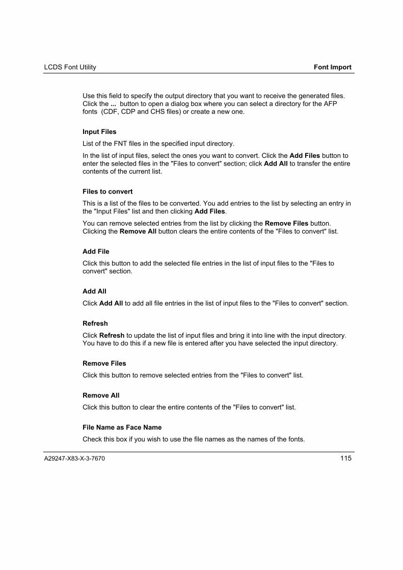
LCDS Font Utility Font Import
A29247-X83-X-3-7670 115
Use this field to specify the output directory that you want to receive the generated files.Click the ... button to open a dialog box where you can select a directory for the AFPfonts (CDF, CDP and CHS files) or create a new one.
Input FilesList of the FNT files in the specified input directory.
In the list of input files, select the ones you want to convert. Click the Add Files button toenter the selected files in the "Files to convert" section; click Add All to transfer the entirecontents of the current list.
Files to convertThis is a list of the files to be converted. You add entries to the list by selecting an entry inthe "Input Files" list and then clicking Add Files.
You can remove selected entries from the list by clicking the Remove Files button.Clicking the Remove All button clears the entire contents of the "Files to convert" list.
Add FileClick this button to add the selected file entries in the list of input files to the "Files toconvert" section.
Add AllClick Add All to add all file entries in the list of input files to the "Files to convert" section.
RefreshClick Refresh to update the list of input files and bring it into line with the input directory.You have to do this if a new file is entered after you have selected the input directory.
Remove FilesClick this button to remove selected entries from the "Files to convert" list.
Remove AllClick this button to clear the entire contents of the "Files to convert" list.
File Name as Face NameCheck this box if you wish to use the file names as the names of the fonts.

Font Import LCDS Font Utility
116 A29247-X83-X-3-7670
FaceEnter a name in this field to assign the font or fonts a custom name.
Change FaceTo change the name of a font or fonts, select the file(s) in the list of files to convert, enter aname in the "Face" field and click the Change Face button.
Change AllClick the Change All button to assign the name entered in the "Face" field to all the fontsin the files to be converted.
ResolutionSelect the resolution of the fonts to be generated: 300 or 600 dpi.
ItalicCheck the "Italic" box if you would like to generate italic fonts.
Code pageSelect the code page that is to be valid for these fonts.
Encoding Mapping TableSelect the mapping table that is to be valid for these fonts. The table is stored in a MAPfile. You can browse for the MAP file you want to use by clicking � next to the "EncodingMapping Table" field. This opens a dialog box for you to make your selection.
Save SettingCheck this box to save the settings for later actions.
Add to FontsInfobaseCheck this box if you wish to enter the converted font in the FontsInfobase.
ConvertClick the Convert button to start the process of converting the fonts in the list of files toconvert.

LCDS Font Utility Font Import
A29247-X83-X-3-7670 117
Generate FontInfoClick the Generate FontInfo button to generate fontinfo files .inf and .cod withoutgenerating AFP fonts.
ExitClick Exit to end the LCDS Font Utility.

Font Import LCDS Font Utility
118 A29247-X83-X-3-7670
LCDS Font Utility Advanced Settings
Use the "Advanced Settings" tab in the LCDS Font Utility window to set the defaults forgenerating fonts for Form Creation and Layout for AFP Line Data.
Fig. 47: LCDS Font Utility Advanced Settings
WeightUse this field to select the weight of the fonts you intend to generate. There are a range ofsettings available, from Ultra-light to Ultra-bold.
WidthUse this field to select the width of the fonts you intend to generate. The available settingsrange from Ultra-condensed to Ultra-expanded.
A, C Space for Rotation

LCDS Font Utility Font Import
A29247-X83-X-3-7670 119
Use these options to specify the A and C space (left-side and right-side bearing) for the90° and 270° character rotation. You can choose between "Uniform Increment" and apercentage value relative to the height.
Output FormatYou can select Relative and MICR for the output format if you intend to work with thesespecial formats.
EncodingSpecify the coding for the default character and variable space character. You can choose"EBCDIC", "ASCII" or "Custom". If you choose "Custom" you have to enter the coding ofthe default character in the "Encoding Customize" section and, if necessary, specify thecode point and increment reference for a variable space character.
Inf FileIn the "Inf File" section, enter the information which cannot be derived from the LCDS fontfile:
• Pitch:
Choose between- Default Pitch = as in original- Fixed Pitch = all characters the same width- Variable Pitch = variable character width (proportional type)
• Family: Select the type family to which the font can be assigned. You can choosebetween Decorative, Modern, Roman, Script and Swiss and Dont Care.
Dont Care means that you cannot search for this font in the FontsInfobase Browser byspecifying a particular family.
• Character Set: Select the character set to which the font corresponds.
Encoding CustomizeIn this section of the dialog box, you enter the code for the default character, and codepoint and increment reference for the variable space character if you have checked"Custom" in the "Encoding" section.
•

Font Import LCDS Font Utility
120 A29247-X83-X-3-7670
LCDS Font Utility Logging
The "Logging" tab shows you the outcome of the conversion process. As well as the totalnumber of files to be converted, you can see how many files were actually converted andhow many the system was unable to convert.
The log also states the source and destination files of each font, the date and time ofconversion, the status of the results and, if necessary, an error code.
Fig. 48: LCDS Font Utility Logging
You can delete the contents of the results list by clicking the Clear button on the tab.

LCDS Font Utility Font Import
A29247-X83-X-3-7670 121
Working with LCDS Font Utility
Follow the steps below to convert LCDS fonts to AFP fonts and generate the files for theForm Creation and Layout for AFP Line Data fonts:
⇒ Click the "Conversion" tab in the LCDS Font Utility window to bring this tab to thefront.
⇒ Specify the input directory containing the FNT files for the LCDS fonts you want toconvert. The FNT files in this directory are then listed in the "Input Files" section. Clickthe ... button to open a dialog box where you can search for and select a directorywith the LCDS fonts (FNT files).
⇒ Specify the output directory that you want to receive the generated files. Click the ...button to open a dialog box where you can select a directory for the AFP fonts (CDF,CDP and CHS files) or create a new one.
⇒ In the list of input files, select the ones you want to convert. Click the Add Files buttonto enter the selected files in the "Files to convert" section; click Add All to transfer theentire contents of the current list.
You can also remove entries from the list of files to convert. Select the entry or entriesand click the Remove Files button. Clicking the Remove All button clears the entirecontents of the "Files to convert" list.
⇒ Specify what the fonts are to be called for Form Creation and Layout for AFP LineData.
# You can use the file names as the names of the fonts. To do this, check the "FileName as Face Name" box.
# You can also change individual names. To do this, select the file in the list of filesto convert, enter a name in the "Face" field and click the Change Face button.
# You can also change all names into a name of your choice; enter a name in the"Face" field and click the Change All button.
⇒ Select the resolution for which you want to generate the fonts: 300 or 600 dpi.
⇒ Check the "Italic" box if you would like to generate italic fonts.
⇒ Select the code page that is to be valid for these fonts.
⇒ Select the mapping table that is to be valid for these fonts. The table is stored in aMAP file. You can browse for the MAP file you want to use by clicking � next to the"Encoding Mapping Table" field. This opens a dialog box for you to make yourselection.
⇒ Bring the "Advanced Settings" tab to the front of the LCDS Font Utility window.

Font Import LCDS Font Utility
122 A29247-X83-X-3-7670
⇒ Specify the weight of the fonts you want to generate. There are a range of settingsavailable, from Ultra-light to Ultra-bold.
⇒ Specify the width of the fonts you want to generate. The available settings range fromUltra-condensed to Ultra-expanded.
⇒ Specify the A and C space (left-side and right-side bearing) for the 90° and 270°character rotation. You can choose between "Uniform Increment" and a percentagevalue relative to the height.
⇒ Select Relative and MICR for the output format if you intend to work with these specialformats.
⇒ Specify the code for the default character and variable space character. You canchoose "EBCDIC", "ASCII" or "Custom". If you choose "Custom" you have to enter thecoding of the default character in the "Encoding Customize" section and, if necessary,specify the code point and increment reference for the variable space character.
⇒ In the "Inf File" section, enter the information which cannot be derived from the LCDSfont file:
# Pitch: Choose betweenDefault Pitch = as in originalFixed Pitch = all characters the same widthVariable Pitch = variable character width (proportional type)
# Family: Select the type family to which the font can be assigned. You can choosebetween Decorative, Modern, Roman, Script and Swiss and Dont Care. Dont Caremeans that you cannot search for this font in the FontsInfobase Browser byspecifying a particular family.
# Character Set: Select the character set to which the font corresponds.
⇒ Check the "Save Setting" box if you want to save the settings for later conversions.
⇒ Check the "Add to FontsInfobase" box if you wish to enter the converted fonts in theFontsInfobase.
⇒ Return to the "Conversion" tab and begin the conversion by clicking the Convertbutton.
The generation process is logged in a separate file. A message is issued when theprocess is completed successfully, and you are asked if you want to view the log file. Thecontent of the log is shown on the "Logging" tab.
Form Creation
A29247-X83-X-3-7670 123
FORMCREATION


Introduction Form Creation
A29247-X83-X-1-7670 125
Form Creation
Develop High-Class Forms ProfessionallyWell laid out forms add structural clarity to complex documents. Readers can pick out thekey items right away and to see at a glance how the information hangs together. A formwith an appealing design will make documents more attractive; by highlighting graphicelements in colour, you can also make sure your document catches and keeps thereader�s attention.
It is expensive to produce and keep forms as pre-printed stock. Electronic forms, on theother hand, are an entirely different proposition. These forms, which are printed with thevariable data, can boost your flexibility in document production and lower your costs.
Form Creation, the forms editor for high performance Océ printing systems, is a powerful,easy-to-use tool for professional development of sophisticated electronic forms.
Being a Windows program, Form Creation makes full use of point-and-click functionalityand the "what you see is what you get" (WYSIWYG) interface, so even new users cancreate their own forms within a short time. Form Creation features advanced graphicsfunctions for ultra-precise design.
There are facilities for directly importing objects from text files and graphic files in a rangeof formats, and you can also create design elements in other Windows applications (suchas Word) and integrate them into your Form Creation forms.
Forms can be proof-printed on all Windows-supported printers.

Form Creation Introduction
126 A29247-X83-X-3-7670
The Form Creation program
FRM(Form Creation)
FONTINFORMATION
(INF)Graphic Text
Form ImportOGL, FSL,
LCDSOLE Objects
(Word, Visio, ...)
WMF / EMF
Form Creation
E-ModeFOB
PCL5eMacro
SPDSMedium OverlayPage Segment
LCDSFRM, IMG
Fig. 49: Form Creation system overview , input and output formats
Forms are designed in Form Creation using
• Graphical elements (lines, boxes, boxes with rounded corners, circles and ellipses)
• The editor for lines and fill patterns
• Text formatting functions (paragraph formatting, text rotation, indents)
• Custom Tone� support (only for SPDS and PCL5 data formats)

Introduction
A29247-X83-X-3-7670 127
An array of functions make working with Form Creation easy
• Editing functions:- Copy- Cut- Paste- Delete- Duplicate- Replicate- Horizontal and vertical alignment- Undelete
• Grid, crosshair, position checks
• Resizing (zoom up and down), normal and full view
• Proof printing
• Entering user comments with forms
• Displaying scanned originals (PCX, TIF, BMP, WMF, EMF) for use as templates
Form Creation also provides functions for
• Integrating data directly from other Windows applications
• Importing text files from any source
• Inserting graphics in any standard format

Form Creation Introduction
128 A29247-X83-X-3-7670
The forms you design with Form Creation can be output in various data formats to suit thesystems environment in which they will be used.
The following data formats are supported:
Printer data stream Resolution (dpi) Custom Tone� Form
SPDS (AFPDS�compatible)
240, 300, 600 X OverlayPage segment
PCL5e- 300, 600 X MacroE-MODE 240 FOBLCDS 300 LCDS (FRM and IMG)
* Cut sheet printers
The output routines for these data formats are implemented by way of Windows printerdrivers. These "printer drivers" generate a print resource in the appropriate format fromyour forms and store the resulting resource in a file.
As well as generating the print resources, Form Creation can also output forms as WMFor EMF files. These files will help you design document layouts with the �Layout for AFPLine Data� or �Layout for SAP RDI Data� program, where they serve as on-screentemplates.

How Form Creation Works Form Creation
A29247-X83-X-1-7670 129
How Form Creation Works
Program Structure
Form Creation basically consists of the editor, with which you develop and design theforms, and the generators for converting the forms to print resources in various formats.The generators are integrated in the form of Windows printer drivers (FILE: creates a fileon disk). You have to have at least one of the Form Creation resource generatorsinstalled.
The advantage of separating the editor and generator is that the Form Creation forms arenot locked into a particular printer data format or resolution. Every form you create in FormCreation can be converted to a resource for any of the supported printing systems simplyby selecting the appropriate generator.
Irrespective of the print resources, the forms you design in Form Creation can also bestored as Form Creation source code in the program�s internal format (FRM format).Forms in FRM files can be opened and edited in Form Creation.
Form Creation Editor
Form Creation operates on the WYSIWYG principle. The form (or section of it) is shownon the screen exactly as it will be when printed. You can perform all editing actions withthe mouse.
All editing in Form Creation is element-based, i.e. you work with objects such as boxesand text blocks. Every element can be assigned specific properties, or attributes � thesize, for example, position, print direction, read-write direction and colour. You can usedefault settings for these attributes or alter the attributes for specific elements.
Form Creation differentiates between two types of settings for element attributes: defaultsettings, which apply to all elements, and individual settings, which are made for onespecific element. Default settings are those settings you define without first selecting anelement on the form. All elements you subsequently place on your form will be assignedthese default settings.
Individual settings are made when an element is selected. They only apply for the designof one specific element. New elements are always created with the default settings.
Each element is assigned its own "level" on the screen display. Elements can be partiallyor completely superimposed by other elements. You can rearrange the levels if you wish(see Chapter:Arranging Elements).

Form Creation How Form Creation Works
130 A29247-X83-X-3-7670
Fonts in the Form
You can use TrueType fonts, outline or bitmapped printer fonts for the text elements inyour Form Creation form. Your choice of font will depend on the format for which the formis intended.
The table below tells you which types of fonts can be used for which formats:
Printer fontsTrueType fonts
Outline Bitmapped
SPDS a a a
PCL a
FOB a a
LCDS a a
Text elements in the form are assigned the name of the font as one of their attributes.
The TrueType fonts installed on your system are also accessible in Form Creation. Whenthe print resources are generated, TrueType fonts are included in the form as graphicelements.
If you intend to use AFP outline or bitmapped printer fonts, the corresponding INF filesmust be present in your Form Creation folder (see installation notes). When the printresource is generated, the text element is stored together with a reference to the printerfont which the element is assigned. These fonts must be available as resources on theprinting system.
When you assign a printer font to a text element, the text is presented on the screen usinga TrueType font which is installed on your system. Form Creation selects the TrueTypefont that corresponds most closely to the printer font.
When you load a form into Form Creation from a form (FRM) file which was created onanother system, you have to find substitutes for any unknown fonts which are present inthe form (i.e. fonts whose names do not occur in the current font database on yoursystem). If Form Creation encounters an unknown font when opening a form, itautomatically opens a dialog box for you to select font substitutes.
Under Windows NT 4.0, Form Creation can manage up to 32,767 fonts in one fontdatabase; under Windows 95 it can manage up to 419.
Form Creation can display a maximum of 150 fonts (font names) with up to four styles(medium, bold, italic and bold italic) and up to 50 sizes. However, you cannot use morethan 166 printer fonts in each form. (Each size of each font counts as a separate printerfont, and requires a separate INF file!) A warning is shown from the 75th font onwards.
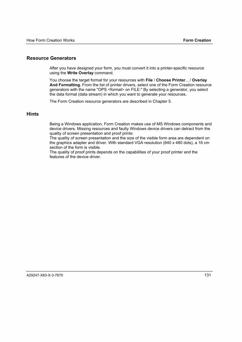
How Form Creation Works Form Creation
A29247-X83-X-3-7670 131
Resource Generators
After you have designed your form, you must convert it into a printer-specific resourceusing the Write Overlay command.
You choose the target format for your resources with File / Choose Printer... / OverlayAnd Formatting. From the list of printer drivers, select one of the Form Creation resourcegenerators with the name "OPS <format> on FILE:" By selecting a generator, you selectthe data format (data stream) in which you want to generate your resources.
The Form Creation resource generators are described in Chapter 5.
Hints
Being a Windows application, Form Creation makes use of MS Windows components anddevice drivers. Missing resources and faulty Windows device drivers can detract from thequality of screen presentation and proof prints:The quality of screen presentation and the size of the visible form area are dependent onthe graphics adapter and driver. With standard VGA resolution (640 x 480 dots), a 16 cmsection of the form is visible.The quality of proof prints depends on the capabilities of your proof printer and thefeatures of the device driver.


User Interface Form Creation
A29247-X83-X-1-7670 133
User Interface
Main window
When Form Creation launches, the workspace window is displayed.
Fig. 50: Form Creation main window (page view � tools, rulers and grids displayed)

Form Creation User Interface
134 A29247-X83-X-3-7670
The workspace window is divided into four sections:
• Windows application border
• menu bar
• Toolbox field with the tools available for designing forms. You can hide the toolbox fieldif you wish.
• Workspace for displaying and editing the form on the screen
The View menu contains commands for adapting the workspace to your preferences.
Windows Application Border
The Windows application border contains:
• The program title
• The name of the current form
• The set resolution
• Colour mode (if enabled)
Note: If the new form has not yet been saved, the entry "no name" is shown insteadof a form name. The resolution is the default resolution of the selectedresource generator.
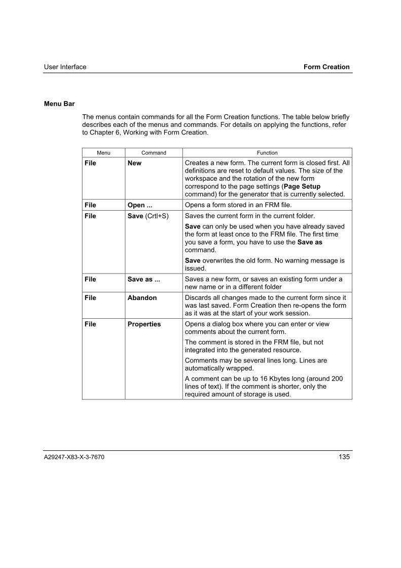
User Interface Form Creation
A29247-X83-X-3-7670 135
Menu Bar
The menus contain commands for all the Form Creation functions. The table below brieflydescribes each of the menus and commands. For details on applying the functions, referto Chapter 6, Working with Form Creation.
Menu Command Function
File New Creates a new form. The current form is closed first. Alldefinitions are reset to default values. The size of theworkspace and the rotation of the new formcorrespond to the page settings (Page Setupcommand) for the generator that is currently selected.
File Open ... Opens a form stored in an FRM file.File Save (Crtl+S) Saves the current form in the current folder.
Save can only be used when you have already savedthe form at least once to the FRM file. The first timeyou save a form, you have to use the Save ascommand.Save overwrites the old form. No warning message isissued.
File Save as ... Saves a new form, or saves an existing form under anew name or in a different folder
File Abandon Discards all changes made to the current form since itwas last saved. Form Creation then re-opens the formas it was at the start of your work session.
File Properties Opens a dialog box where you can enter or viewcomments about the current form.The comment is stored in the FRM file, but notintegrated into the generated resource.Comments may be several lines long. Lines areautomatically wrapped.A comment can be up to 16 Kbytes long (around 200lines of text). If the comment is shorter, only therequired amount of storage is used.

Form Creation User Interface
136 A29247-X83-X-3-7670
Menu Command Function
File Page Setup Use the Page Setup command to define the defaultpage setup to be applied when generating the printresources (overlays) from the current form. The pagesetup dialog box corresponds to those of otherWindows printer drivers.The available settings depend on what resourcegenerator you are using. For details, please refer toChapter Resource Generators.Only two settings � Paperformat and PageOrientation � have a direct impact on the way theform is displayed on the workspace.Page Orientation defines whether the page will havea portrait or landscape orientation .Paperformat defines the size of the workspace. Setthe smallest possible format for your form, since thisgives you greater flexibility for integrating your forminto print jobs without performance loss.To change the default values for all new forms,choose Printers in the Windows Control panel andopen the setup dialog box for the Form Creationresource generator concerned.
File Import ExternalForm...
Launches the Form Import program, which convertselectronic forms from other formats to the internal FRMformat.The command is only available if you have FormImport installed on your system.For a detailed description of the Form Import program,the Form Import interface and how to use the program,please refer to chapter Form Import.Following the import of an external form and itsconversion to FRM format, Form Creation displays thepage setup dialog box. This allows you to check andmodify parameters (e.g. the resolution) if necessary.

User Interface Form Creation
A29247-X83-X-3-7670 137
Menu Command Function
File Write Overlay Starts the generation of an overlay print resource.Depending on the printing system, you may have toprovide additional information. For details, refer to thedescriptions of the resource generators in Chapter 5.When you generate an overlay, you can also chooseto generate a Windows Metafile (WMF and/or EMF).Do this by setting the Write Overlay Metafile ascommand in the Options menu.
File Proof Print(Crtl+P)
Outputs the current form on a PC printer. You select aprinter and specify settings using the File / ChoosePrinter / Proof Print command.
File ChoosePrinter...
Opens the Choose Printer For dialog box, where youcan choose an resource generator for generating theprint resources and formatting the form, or a PC printerfor making proof prints.Overlay And Formatting:Opens a dialog box for selecting an resourcegenerator.Proof Printing:Opens a dialog box for selecting a printer for proofprints.
File Quit Exits the program.Should you not already have saved your work, FormCreation prompts you to save the form you are workingon. In the dialog box that displays, choose Yes to saveyour form or No to discard it. You can also cancel thequit procedure at this point.
Edit Undelete(Alt + Back)
Cancels a Delete command and inserts the deletedelement or element group back into the form. Theformatting of the deleted elements and their positionremain the same.It is not necessary to choose the Undelete commandimmediately after Delete, because Undelete can onlyrestore the last element to be deleted.
Edit Cut(Crtl + X)
Removes selected elements from the form. Theelements are copied to the Windows clipboard.The Paste function enables you insert the elementsback into your form.

Form Creation User Interface
138 A29247-X83-X-3-7670
Menu Command Function
Edit Copy(Crtl + C)
Copies all selected elements to the clipboard. All theelement parameters, including their position on theform, are retained.Use Paste to copy the content of the clipboard intoyour form.
Edit Paste(Crtl + V)
Copies elements from the clipboard into your form.Form Creation elements retain all their parameters �including their position on the form � when they arecopied to the clipboard.When you are copying elements from anotherWindows application via the clipboard, the mousepointer displays as the graphic icon; when you arepasting text, you will see a text icon.The formatting of text from other windows applicationsis lost. These texts are presented in the default font. Ifyou wish, you can reformat the texts using the texttools.The elements remain buffered in the clipboard,meaning that you can integrate them into your form asmany times as you wish.
Edit Duplicate(Crtl + D)
Creates a copy of selected elements.The copy is inserted into the form horizontally andvertically offset from the original.To specify the horizontal and vertical offset, chooseDuplicate Settings from the Options menu.The Duplicate command is thus a shortcut for theCopy and Paste command sequence, the differencebeing that the selected objects are not copied to theclipboard.

User Interface Form Creation
A29247-X83-X-3-7670 139
Menu Command Function
Edit Replicate(Crtl + R)
Copies selected elements or groups of elementsmultiple times.You must set the following parameters:Replicate ObjectSpecify how many times the selected elements are tobe copied in both the horizontal and vertical directions.(Example: If you enter four for horizontal and three forvertical, the selected objects are copied a total of 12times and placed in a rectangle.)
Distance between objectsSpecify how far the copies are to be apart. Bear inmind that you specify the effective distance betweentwo individual copies, and not � as with DuplicateSettings � the offset of the copy compared to theoriginal.
When you confirm with OK, Replicate cascades thecopies across and down, each copy being thespecified distance from the next. The copies have thesame parameters as the original. The top left corner ofthe original remains constant.
Edit Delete (Del) Deletes selected elements.Edit Select all Selects all the elements simultaneously; the command
is only available when the pointer tool is active.Edit Tool Selects a tool.
You can select tools in this way if you have chosen notto display the tool buttons (Toolbox command in theView menu).

Form Creation User Interface
140 A29247-X83-X-3-7670
Menu Command Function
Insert Text... Opens a dialog box where you select a file.You can import ANSI and MS DOS text files (*.TXT) ofany size. There is no limit to the number of texts youcan import.Select the file type: "Textfiles (*:TXT)" or "MS-DosTextfiles (*:TXT)": this defines the character codingthat will be used to interpret the file. The setting "MS-Dos Textfiles" interprets the text in the form in which itwas saved with MS-Dos Edit (OEM character set).With the setting "Textfiles", Form Creation assumesthe text was created using a program such as Notepad(ANSI character set). The fonts differ in terms of thecodes assigned to certain special characters andsymbols.When you open a text file, the mouse pointer changesinto the text tool. Click the required position on theworkspace to integrate the text into your form, or draga box to the requisite size.Imported texts are presented with the standard fontand have to be reformatted, since formattinginformation is lost when the text is imported (seeFormat menu).If the text is not fully visible, you must resize the textwindow using the pointer tool.
Insert Graphic... Opens a dialog box where you select a file.When you open a graphic file, mouse pointer changesinto the shape of a graphic icon. Move the pointer towhere you want to position the image, then click onceto insert the image at its original size. You can alsoresize the graphic by dragging a rectangle with themouse: Form Creation then fits the graphic into thisrectangle.Since bitmap refresh can slow down processing, youcan turn off the display of graphics using the Graphicstoggle command in the View menu. A placeholder isshown instead of the graphic.
Insert Object... Inserts OLE objects. (see Chapter: Importing Objectsfor further details on inserting Windows objects)
Insert ExternalReferences...
Inserts references for external page segments.
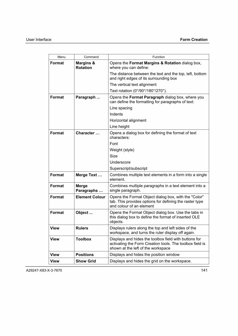
User Interface Form Creation
A29247-X83-X-3-7670 141
Menu Command Function
Format Margins &Rotation
Opens the Format Margins & Rotation dialog box,where you can define:The distance between the text and the top, left, bottomand right edges of its surrounding boxThe vertical text alignmentText rotation (0°/90°/180°/270°).
Format Paragraph ... Opens the Format Paragraph dialog box, where youcan define the formatting for paragraphs of text:Line spacingIndentsHorizontal alignmentLine height
Format Character � Opens a dialog box for defining the format of textcharacters:FontWeight (style)SizeUnderscoreSuperscript/subscript
Format Merge Text � Combines multiple text elements in a form into a singleelement.
Format MergeParagraphs �
Combines multiple paragraphs in a text element into asingle paragraph.
Format Element Colour Opens the Format Object dialog box, with the "Color"tab. This provides options for defining the raster typeand colour of an element
Format Object ... Opens the Format Object dialog box. Use the tabs inthis dialog box to define the format of inserted OLEobjects.
View Rulers Displays rulers along the top and left sides of theworkspace, and turns the ruler display off again.
View Toolbox Displays and hides the toolbox field with buttons foractivating the Form Creation tools. The toolbox field isshown at the left of the workspace
View Positions Displays and hides the position windowView Show Grid Displays and hides the grid on the workspace.

Form Creation User Interface
142 A29247-X83-X-3-7670
Menu Command Function
View Long Mouse Displays a crosshair on the workspace with the toolpointer. The crosshair covers the entire workspace.
View BackgroundImage
Turns the display of a background image on and off.
View Graphics Displays and hides graphicsView Objects Displays and hides objectsView External
ReferencesDisplays and hides images for external references
View Normal View /Full View(right mousebutton)
Use this command to indicate how you want the formto be presented on the workspace. In "Full view" mode,the form is scaled down such that the entire page isvisible on the workspace. In "Normal View", theworkspace in the main window shows a section of theform for editing.
View Zoom In(Crtl + +)
Enlarges the presentation of the form on theworkspace in steps up to four times its real size.
View Zoom Out(Crtl + -)
Returns the presentation of the form step-by-step tonormal display size.
View Redraw Recalculates and redraws the entire contents of theworkspace.
Arrange Align Aligns a group of selected elements horizontally andvertically to a line.
Arrange To foreground Brings an element into the foreground.Arrange To background Sends an element to the background.Arrange One up Brings an element one level forward.Arrange One down Sends an element one level back.Graphic Corners... Opens the "Rounded Rectangle" dialog box, where
you set the rounding of the corners of a rectangle.Graphic Line Settings ... Opens a dialog box where you set the line width and
the style of line end.Graphic Edit Line
Types...Opens a dialog box where you can define the linestyle. Form Creation lets you use up to eight editabletypes of line (plus the solid line type) in each form.These can be selected by choosing a line (Line 1 toLine 8) in the Graphic menu.
Graphic Normal Selects the normal line style.

User Interface Form Creation
A29247-X83-X-3-7670 143
Menu Command Function
Graphic Line 1 Line 8 Use these commands to select a line style (see EditLine Types...)
Fill none Sets the fill pattern of a closed graphic object to "none"Fill white ... solid Sets the fill pattern of a closed graphic object. You can
choose from eight levels (white to solid)Fill pattern Opens a dialog box where you can choose from eight
predefined fill patterns. You can also define a custompattern of your own (in a further dialog box).
Fill coverage... set...
Coverage in %Opens a dialog box where you can choose thecoverage in %
Options Language /Sprache
Opens a dialog box where you can change thelanguage of the menus and help text.
Options Ruler Settings... Opens a dialog box where you can set the measuringunit of the horizontal and vertical Form Creation rulers.You can make different settings for each ruler.
Options Grid Settings... Opens a dialog box where you can set the horizontaland vertical grid increments. You can make differentsettings for the X and Y axes.
Options DuplicateSettings...
Opens a dialog box where you can specify where youwant to place a duplicate (horizontal, vertical) inrelation to the original.
Options Colour Mode... Opens a dialog box where you can set the colourmode for presenting the elements in the editor
Options Full-ViewCentered
Centres the page view or displays it left-aligned
Options Check ForClipped Text
Checks whether your form includes texts that are toolarge for the boxes in which they are positioned.
Options BackgroundImage...
Opens a dialog box where you can load, position andremove background images
Options Write OverlayMetafile As...
Opens a dialog box where you can choose to generatemetafiles (WMF/EMF) along with your overlays. Youcan generate them without a rotation or in the directionof printing.
? Contents Opens the contents page of the online help.? About Form
Creation...Tells you which version of Form Creation you areusing.
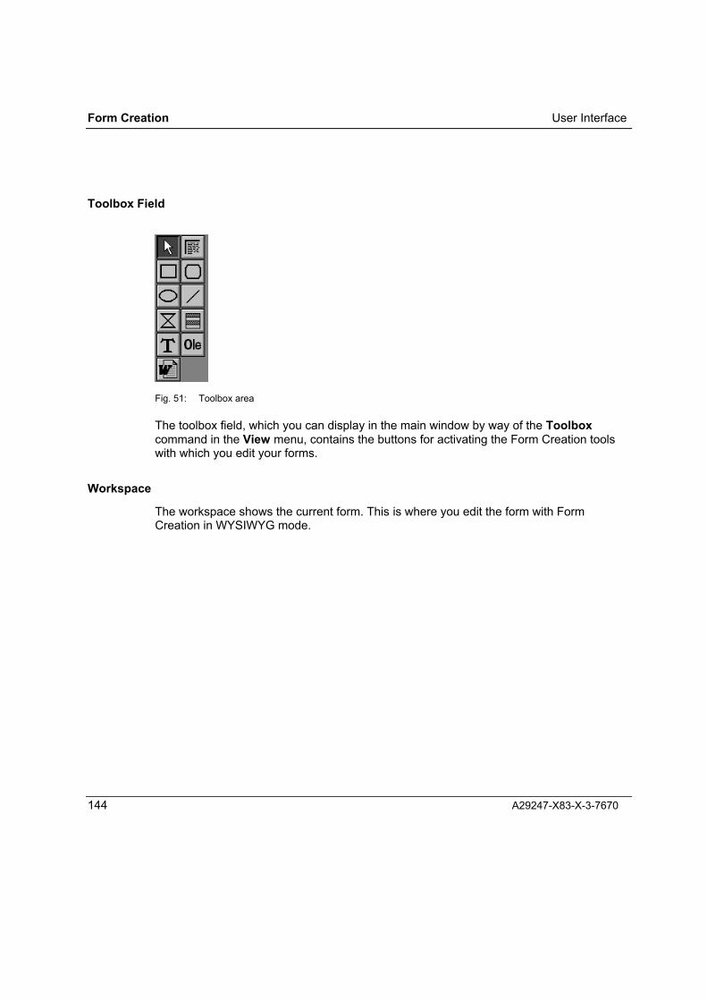
Form Creation User Interface
144 A29247-X83-X-3-7670
Toolbox Field
Fig. 51: Toolbox area
The toolbox field, which you can display in the main window by way of the Toolboxcommand in the View menu, contains the buttons for activating the Form Creation toolswith which you edit your forms.
Workspace
The workspace shows the current form. This is where you edit the form with FormCreation in WYSIWYG mode.

Program Tools Form Creation
A29247-X83-X-1-7670 145
Tools
Form Creation provides a suite of tools for editing forms. You activate the tools viaEdit/Tool, using toolbar buttons or keyboard shortcuts. Each tool has a specific cursor.
Pointer Tool
Use this tool to select objects for editing. It can be used with any object on your form.
Tool Button Keyboard shortcut Cursor Task
Pointer Crtl+1 Select elements
Graphic Tools
Use the box, rounded box, ellipse, line, polygon (polyline) and read line tools to drawthese styles of graphic elements.
Tool Button Keyboard shortcut Cursor Task
Box Crtl+3 Draw a rectangle
Roundedbox Crtl+4 Draw a rectangle with
rounded corners
Ellipse Crtl+5 Draw a circle or ellipse
Line Crtl+6 Draw a line
Polyline Crtl+Shift+1 Draw a polyline
Read lines Crtl+7 Create a block of read lines
Text Tools
Use the text tool to create text elements; use the paragraph tool to select paragraphs.

Form Creation Program Tools
146 A29247-X83-X-3-7670
Tool Button Keyboard shortcut Cursor Task
Text Crtl+8 Enter text
Paragraph Crtl+2 Select a paragraph of text
OLE Tools
You use the object tool to access other Windows applications in order to create new OLEobjects that are to be included in your form.
The Word document tool launches MS-Word, where you create the Word document thatyou intend to import into the form design as an OLE object.
Tool Button Keyboard shortcut Cursor Task
Object Crtl+9 Create OLE object
Worddocument Crtl+0 Create Word object
Chapter 6.3.1, Working with Form Creation Tools, describes in detail how you use thesetools in designing your forms.

Forms Generators Form Creation
A29247-X83-X-1-7670 147
Resource GeneratorsThe resource generators create a print resource in a particular format from the forms youdesign in Form Creation.
The resource generators are implemented in the form of printer drivers. They are installedin your PC system in the same way as printer drivers: the generators are copied into theWindows System folder, added to the list of Windows printer drivers and connected to theFILE: port.
Default settings of the resource generators:Following the installation of an resource generator you are shown the dialog box formaking the device settings. Here you can define the default settings for the generator.These settings will be used as the defaults when you launch the generator from FormCreation.
You can modify the default settings in Windows by going via the Control panel. To openthe printer window, choose Start / Settings / Printers.
Fig. 52: Windows settings: printers

Form Creation Forms Generators
148 A29247-X83-X-3-7670
Select one of the available resource generators as your printer and choose Propertiesfrom the File menu. This opens the "Properties" dialog box for the generator concerned.
Fig. 53: Windows dialog box for printer properties
On the "Device Settings" tab, you can make the default settings for the selected resourcegenerator. Bear in mind that the port "FILE" has to be selected for the generator on the"Ports" tab.
In Form Creation you can change the resource generator settings for the current formusing theFile / Page Setup command � these changes do not impact on the default settings.

Forms Generators Forms Creation
A29247-X83-X-3-7670 149
Selecting a resource generator:In Form Creation you select a resource generator with the File / Choose Printer...command; you then choose a printer for Overlay And Formatting.
Your selection of resource generator defines the data format in which the print resourcewill be generated.
The various formats permit different settings for the resolution of the printer. In addition,your choice of resource generator also determines whether or not you will be able to useCustomTone�. You can only define CustomTone� in the forms you develop for SPDS orPCL resources.

Form Creation SPDS Generator
150 A29247-X83-X-3-7670
SPDS Generator
Working under Form Creation, the SPDS Generator creates print resources in the SPDSdata format from the forms you design with the Form Creation tools.
The SPDS Generator is implemented as a printer driver that is launched from within anForm Creation session. The generator creates a file in SPDS format from the current form.You can transfer this file to the host system or printing system using suitable file transfersoftware. The form is used in the printing process as an overlay or page segment.
If you use printer and AFP outline fonts, font information files (*.INF) corresponding tothese fonts are required for presenting text in Form Creation. Text presented with thesefonts is not converted to bitmap format in SPDS print resources because the charactersare referenced by means of character code (text controls). Text in printer and AFP outlinefonts will be transferred with colour information, so they can be reproduced in colour withCustomTone� or as white text.
TrueType fonts and all the other elements of the form are converted into bitmap patterns(IOCA) in the SPDS print resource.
Fonts TrueTypeAFP outlinePrinter fonts
Converted to graphicsReference (identification, size)Reference (identification)
Graphics Bitmaps, uncompressedBitmaps, compressedExternal references
IM imagesIOCA � FaxG4Page Segments
Colour Black/whiteCustomTone�
Resolution 240 x 240 dpi300 x 300 dpi600 x 600 dpi
Output format SPDS Binary, Hex, TRANS1

SPDS Generator Form Creation
A29247-X83-X-3-7670 151
SPDS Settings
Fig. 54: SPDS device settings in Windows NT
The current settings are shown in blue type, enclosed in angled brackets. If you edit adevice setting, the changed setting is displayed in red until you click OK to confirm. Youcan discard all changes and restore the original settings by clicking the "Undo ChangedOption" button, provided you have not yet confirmed the dialog box with OK.
Click "About OPS SPDS..." to display details about the installed SPDS Generator software(product number, series number, and version numbers of relevant software components).

Form Creation SPDS Generator
152 A29247-X83-X-3-7670
Printer Type
Fig. 55: SPDS settings: printer type
When you select a printer type, you also define
• the maximum possible width and length of the paper;
• the possible resolutions of the destination printer;
• the possible colour options.
When you have selected a particular type of printer, you can only make settings for theresolution, paper size and colour mode that are actually supported by the type of printeryou intend to use. The defaults also automatically switch to values that the printersupports.
If you select "ANY" as the type of printer, the list of values for the resolution, paper sizeand colour mode contain all the available options.

SPDS Generator Form Creation
A29247-X83-X-3-7670 153
Resolution:
Depending on the capabilities of the printer you have selected, you can choose 240 x240 dpi, 300 x 300 dpi or 600 x 600 dpi. If you select "ANY" as the type of printer, youcan select any of the three resolutions.
Select Font Database:
Fig. 56: SPDS settings: fonts
Use this option to set the path (folder) of the font database and/or to create a new fontdatabase (SUM file) in the selected folder. The font database contains the available fontsin the form of INF files.
When the Océ PRISMAtools are installed, a range of fonts for 240, 300 and 600 dpi arecopied to the folders ...\OPSTOOLS\FONTS\SPS240\, ...\SPS300\ and ...\SPS600. As thedefault font folder, the system automatically selects the folder with fonts that match theprinter output resolution you have selected. The path of the current font database isshown in the device settings dialog box next to the "Select Font Database" entry in the listand on the "Select Fontdatabase button".
To select a different font database, click the "Select Fontdatabase button". This opens adialog box for you to select the folder containing the fonts you want to use.

Form Creation SPDS Generator
154 A29247-X83-X-3-7670
Fig. 57: Dialog box for selecting a font folder
The folder must contain the INF files with the fonts, the corresponding conversion tables(COD files), plus the font database (SUM file). Click OK to confirm the folder. If there is nofont database in the specified folder, you are asked if you want to create a new one. Afteryou confirm, the generator creates a database from the INF files using the conversion file(COD) for mapping.
Fig. 58: Generating a font folder
Click the "Create Fontdatabase button" to create the new font database in the selectedfolder. You have to execute this function in order to update your database � for example,each time you add a new font to your collection.

SPDS Generator Form Creation
A29247-X83-X-3-7670 155
Paper and Format Settings
Fig. 59: SPDS settings: paper and direction
Page Orientation:Use this option to specify whether the area defined for "Paper Size" is to be a portrait orlandscape page. Choose "Landscape" to have the long edge of the form on top, and"Portrait" to have the long edge at the side.
Paper Size:

Form Creation SPDS Generator
156 A29247-X83-X-3-7670
Fig. 60: SPDS settings: paper size
Use this option to define the area covered by the form � the logical page. This may be thesame size as or smaller than the physical page.
You can choose from a range of standard formats. Choose the smallest possible size forthe form, since this gives you more scope for positioning it on the physical page. If none ofthe standard sizes are suitable, you can set a custom size. To do this, click the "Selectother size" button.
In the dialog box that opens, enter the size of paper you want to use.
The setting you make can then be selected and modified by choosing "Custom Size" inthe list of formats.
Fig. 61: SPDS settings: specifying a custom size
Print Direction:
Fig. 62: SPDS settings: print direction

SPDS Generator Form Creation
A29247-X83-X-3-7670 157
Use this option to indicate how the logical page defined by "Paper Size" and "PageOrientation" is to be placed or rotated on the physical page. You can thus rotate yourforms irrespective of the write direction of the variable data.

Form Creation SPDS Generator
158 A29247-X83-X-3-7670
Output
Fig. 63: SPDS settings: output
Type:Use this option to specify what type of SPDS resource you want to generate. You cancreate overlays and page segments.
Overlays contain all the form elements in bitmapped form.
In page segments, the printer and AFP outline fonts do not become bitmaps � they areoutput in the form of text controls. When you are generating page segments, rememberthat the text in the segments will be printed using the fonts assigned in the overlay or pagedefinition in which the page segment is called.
Images:Use this option to indicate whether images in your form are to become raster images (IM)or IOCAs (IO) in the compiled SPDS print resource.

SPDS Generator Form Creation
A29247-X83-X-3-7670 159
Images are compressed in IOCA format (Image Object Content Architecture). The SPDSGenerator compresses IOCA data using the Fax G4 compression algorithm.
Images in IOCA format take up far less storage/memory than in bitmap format. Beforeselecting IOCA format for the images in the SPDS print resource, you should verify thatthe destination printer can in fact process IOCA images.
Colour Mode:You can select either "Monochrome" or "Highlight Colour" for the colour mode.
If you choose monochrome, all the elements in the form are generated in one and thesame colour in the resource created by the SPDS Generator, irrespective of what colourthey are assigned in Form Creation and what colour mode is selected in Form Creation.All elements are printed with the printer's standard colour.
If you select "Highlight Colour" and have also chosen to display either highlight colour orelement colour as your colour representation in Form Creation, all colour elements in theform will be compiled into the print resource with the attribute "highlight colour",irrespective of their actual colour in the Form Creation program. These elements areprinted with the printer's highlight colour.
Halftoning:The raster width can be set for graphics and shading . Raster Width (in lpi = lines perinch) is used to define the number of raster points in a specific area. With less preciseraster widths, multiple points are combined into one. This is useful if surfaces aredisplayed with irregular colouring (�cloudy�) at a high resolution.
240 x 240 dpi 300 x 300 dpi 600 x 600 dpi
Fine screeningMedium screeningCoarse screening
57 lpi42 lpi
n.a.
71 lpi53 lpi
n.a.
142 lpi106 lpi
85 lpi
Format:Use these options to specify the output format in which you want to compile the SPDSprint resources.
TRANS1 ASCII file, double-byte format, max. 80 positions, CRLF as logicalseparator, HDR records, suitable for ASCII transfer to host (like textfiles), with subsequent re-conversion using TRANSLIB program.
HEX ASCII file, double-byte format, max. 80 positions, CRLF as logicalseparator.
Binary: Binary file, single-byte format, no CRLF.

Form Creation SPDS Generator
160 A29247-X83-X-3-7670
Since the resources generally have to be sent to the host system via a PC-host filetransfer interface, we advise setting this option to TRANS1 (TRANS format).
Tile Size:Use this option to indicate whether or not the overlay is to be output in tiles and, if so, howlarge they are to be.
The form cannot be tiled when it is output as a page segment, so no compression ispossible.
The possible settings for overlays are:
• Small tiles (64 x 64 pels
• Medium tiles (128 x 128 pels)
• Large tiles (256 x 256 pels)
• Custom Size
• No tiles
To define a size of your own, click the "Select Custom Tilesize" button. This opens adialog box for you to enter the width and height of the tiles. Values must be multiples ofeight.
Fig. 64: Selecting a custom tile size
Tiles containing no elements or element sections are skipped in the output, so a smallertile size results in an overlay that requires less space on disk. The drawback is that it cantake much longer to generate an overlay with a small tile size. You should choose thesetting that is most suitable for the composition of the form.

SPDS Generator Form Creation
A29247-X83-X-3-7670 161
General Options
Fig. 65: SPDS settings: system values
General options (system values) can only be defined as defaults. You can make thesesettings during the installation process. To change the defaults later, you have to go viathe Settings / Printers command in the Windows system menu.
You can change the following settings on the "Device Settings" tab in the "OPS SPDSProperties" dialog box:
• Compress tiles
• Align tiles to minimum size 32x32
• Tile optimisation
• Logical units for text positions

Form Creation SPDS Generator
162 A29247-X83-X-3-7670
Compress Tiles:Use this option to specify whether the generator is always to output the entire tile, orwhether lines and columns without any data are to be skipped.
By suppressing empty lines and columns you can substantially reduce the size of yourSPDS print resource.
Align Tiles to Minimum Size 32x32:Use this option to align tiles to a 32 x 32 point grid.
You should generally turn this option on; however, it is only of benefit if you have specifiedtile width and height values that are multiples of 32.
Tile Optimization:Use this option to specify that identical tiles should be transferred once only. Thissubstantially reduces the size of the SPDS print resource.
Logical Units for Text Positions:The units for positioning text are given in "Logical Units per Unit Base". The unit base hereis 10 inches.
You can set the following values for placing text:
• Ten times the selected resolution (at a resolution of 600 dpi, for example, the value is6000 Logical Units per Unit Base)
• 2400 Logical Units per Unit Base
• 14400 Logical Units per Unit Base

PCL Macro Generator Form Creation
A29247-X83-X-3-7670 163
PCL Macro Generator
Working under Form Creation, the PCL Macro Generator generates PCL5e macros fromthe form you are currently designing with the Form Creation tools. The resulting macroscan be used as print resources. .
The PCL Macro Generator is designed for Océ Pagestream printers with SRA controller.
Features of PCL5e-:PCL5 is a superset of PCL4, adding publishing functions to the PCL4 functionality. PCL5eincludes functions for font scaling and HP-GL/2 graphics. The SRA controller does notsupport the HP-GL/2 commands. This is indicated by the minus sign �-� in PCL5e-. Forfurther details, see the reference manual "PCL5e for SRA Controller".
How fonts are handled:The PCL Macro Generator can handle TrueType fonts in different ways.
• Print TrueType fonts as graphics,
• Convert fonts to bitmap fonts (softfonts),
• Reference TrueType fonts as outline fonts
The OPS PCL Macro Generator always generates bitmap fonts (soft fonts).
Print margins:The PCL Macro Generator usually generates PCL macros that cover the entire area of thepaper format. PCL printers that have a nonprinting margin on the paper will shift the forminto the printable area � and this means the form�s position is offset. To counter this effect,you can specify an offset value when you generate the PCL macro.
When you make an Form Creation proof print, the part of the macro that lies in the marginzone is not printed.

Form Creation PCL Macro Generator
164 A29247-X83-X-3-7670
Restrictions:The following restrictions at present apply to the PCL Macro Generator:
• Double-byte fonts are not supported.
• No further macro can be referenced within a macro that was generated with FormCreation.
• For CustomTone�, two independent colour spaces (black and white, highlight colour)are used. Interference effects (e.g. overlaps) between colour spaces are notsupported.
Overview of PCL format properties:
Fonts TrueType Converted to softfonts (optimised) Graphics (bitmap, relative bitmap)
Graphics Bitmaps Optimised (fonts: softfonts)BitmapRelative bitmap
Colour Black/whiteCustomTone�
Resolution 300 x 300 dpi600 x 600 dpi
Output format PCL5e- macro Binary, TRANS1
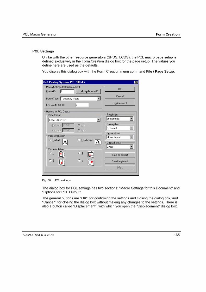
PCL Macro Generator Form Creation
A29247-X83-X-3-7670 165
PCL SettingsUnlike with the other resource generators (SPDS, LCDS), the PCL macro page setup isdefined exclusively in the Form Creation dialog box for the page setup. The values youdefine here are used as the defaults.
You display this dialog box with the Form Creation menu command File / Page Setup.
Fig. 66: PCL settings
The dialog box for PCL settings has two sections: "Macro Settings for this Document" and"Options for PCL Output".
The general buttons are "OK", for confirming the settings and closing the dialog box, and"Cancel", for closing the dialog box without making any changes to the settings. There isalso a button called "Displacement", with which you open the "Displacement" dialog box.

Form Creation PCL Macro Generator
166 A29247-X83-X-3-7670
DisplacementUse this button to open a dialog box where you can define how far the form is to bedisplaced on the paper.
Fig. 67: PCL "Displacement" dialog box
Use the values to position the form on the print medium. In the PCL macro, the form isdefined as having the size of the selected paper format. You can define a displacementvalue to counter the effect of any nonprinting margin on the paper.
Form shiftedleft and up
Form positionwithout displacement
FormPaper withnonprinting margin
Fig. 68: Shifting a form to offset a nonprinting margin zone
You can enter the displacement (shift) value in centimetres or inches, and specify positiveor negative values.
The shift setting is a global setting for the PCL printing system on which you intend to printthe PCL macros. Once defined, the setting is valid for all PCL macros you subsequentlygenerate. The setting is not stored in the Form Creation form file (FRM).
Macro Settings for this DocumentIn the "Macro Settings for this Document" group box, specify the Macro ID and MacroType. By clicking the "List all used macro IDs" button, you can find out which macro IDshave already been assigned.

PCL Macro Generator Form Creation
A29247-X83-X-3-7670 167
Macro ID:You can assign a number between 0 and 32767 to identify the macro to be generated.
List of macro IDs:Since a macro will be overwritten in the printing system if you load another macro with thesame ID, the dialog box contains a button called "List all used macro IDs" for finding outwhich PCL macros have already been generated with Form Creation and stored on thePC hard disk.
Fig. 69: List of macro IDs already in use
When you click the "List all used macro IDs" button, a list is displayed of the PCL macrosalready generated in the selected macro path. The system searches for all files with theextension PCL or MAC - depending on what extension has been adjusted for thegeneration of macros (see chapter Generating a PCL Macro). The resulting list is sortedby macro ID. PCL files without a macro parenthesis are not listed.
The default macro path can be changed using the "Select Macro Path" button. Clickingthis button opens a dialog box where you select the path you want to use.
Form Creation PCL Macro Generator
168 A29247-X83-X-3-7670
Macro Type:The Macro Type list box contains six options to choose from:
• No macroPCL code only is generated, but no macro parentheses
• Temporary Macro (ESC &f9X)The system generates a temporary macro which is deleted by the PCL Printer Resetcommand (ESC E) or when the printing system is powered down.
• Permanent Macro (ESC &f10X)The system generates a macro that is not deleted until the printing system is powereddown.
• Automatic Overlay (ESC &f4X)The system generates a temporary macro that is printed automatically on every page.
• PRISMAnet MacroThe system generates a macro of the type "No macro" with special margin settingsfor PRISMAnet.
• JEC TicketThe system generates a special macro for the Océ 9200 printer series (for details see9200 Series Programmer�s Guide). This function is not available if you select"Standard" optimisation mode.
First Used Font IDThis field is only active when the setting Optimized is selected in the "Optimization" box.The valid range of IDs is 0 - 65535.
If you select Standard as your optimisation setting, the parameter "First used Font ID" isautomatically set to 16534 and cannot be changed.
If Bitmap is chosen, the entire macro � including its fonts � is generated as a full-pagebitmap, and fonts are therefore part of the graphic information.

PCL Macro Generator Form Creation
A29247-X83-X-3-7670 169
Options for PCL Output
PaperformatThe paper format is selected from the "Paperformat" list. You can select a predefinedformat or define your own with "Custom Size". If you select "Custom Size", a separatedialog box opens for you to enter the page dimensions in cm or inches.
Page OrientationThe dialog box for the page settings provides two options for the page orientation: Portraitor Landscape.
Print OrientationYour choice of print orientation determines the direction in which the form will bepositioned on the page for printing.
Note: When you rotate a macro, take care that it remains positioned inside theprintable area of the printer!
The chosen direction of rotation will also be applied to the WMF / EMF files (these filesare only generated if you have selected Write Overlay Metafile As in the Options menu).
ResolutionUse this field to select the resolution in which you intend to print the form. The PCL MacroGenerator can generate macros that describe forms for 300 x 300 dpi or for 600 x 600 dpi.
Optimisation SettingsUse these options to determine how the form will be described in the PCL macro and howit will be called in the printing process.
The PCL Macro Generator permits various levels of optimisation
• Optimized
• Bitmap
• Relative Bitmap
An additional option, "Standard", is available under Windows 95.

Form Creation PCL Macro Generator
170 A29247-X83-X-3-7670
The effect of these settings is:
Optimized Creates a macro containing bitmap soft fonts. The start ID for thesequence of soft fonts is the first used font ID.
The compression methods are Delta Row and RLE.
Choose this setting when you are generating macros inCustomTone� mode.
Standard Creates a macro containing bitmap soft fonts. The start ID for the softfonts is set to 16534.
The Delta Row and TIFF compression methods are used.
Unlike in optimised generation, rotated texts are also rasterised asbitmap soft fonts, using the PCL Print Direction command. Macros withrotated texts can only be rotated by the calling application using thePCL Page Orientation command.
You can only set "Standard" when you are working in Windows95!
Bitmap The entire PCL macro is generated as a bitmap.
Relative Bitmap The PCL macro is generated as a bitmap, but without absolute positionco-ordinates. A macro generated as a relative bitmap will be printed atthe current cursor position, and not at the page origin.
Note:The settings Standard and Optimized cause bitmap soft fonts to be generated. Fonts arenumbered beginning with the specified start ID. The number is incremented automaticallyfor each new soft font in the macro.
Like with macros, a soft font with the same ID as a font already loaded in the printingsystem will overwrite the original font. For this reason, you must ensure that soft fontscannot be overwritten unintentionally. (Different start IDs can be assigned, for example).
Examples:Example 1:
A PCL application uses the bitmap soft fonts with IDs 0, 1, 2 and 255. The application alsocalls a macro (an invoice form). This macro loads the soft fonts 16534, 16535 and 16536.

PCL Macro Generator Form Creation
A29247-X83-X-3-7670 171
Since there is no overlap between the font ID ranges, both the application and the macroare executed as intended.
Example 2:
A second application uses the bitmap soft fonts with IDs 255, 16534, 16535 and 16536.This application also calls the macro in example 1 (font IDs: 16534, 16535 and 16536).
In this case, the two font ID ranges do overlap. Some of the soft fonts of either theapplication or the macro will be overwritten, depending on which set is loaded first:
First Case:If the macro is loaded first, followed by the soft fonts belonging to the application,both the application and the macro are executed as intended.
Second Case:If, on the other hand, the soft fonts belonging to the application are loaded first,followed by the macro, the application will be executed using the macro fonts.
Colour ModeUse this option to choose whether to generate macros with highlight colour ormonochrome colour.
Monochrome: All elements are printed in black, regardless of whether they havebeen assigned a colour or not.
Highlight Colour: All elements that are not black are printed in CustomTone�.
Output FormatUse these options to specify the output format of the PCL macro. Choose betweenTRANS1 and binary.
TRANS1 ASCII file, double-byte format, max. 80 positions, CRLF as logical separator,HDR records, suitable for ASCII transfer to host (like text files), withsubsequent re-conversion using TRANSLIB program.
Binary Binary file, single-byte format, no CRLF.
Halftoning:The raster width can be set for graphics and shading . Raster Width (in lpi = lines perinch) is used to define the number of raster points in a specific area. With less preciseraster widths, multiple points are combined into one. This is useful if surfaces aredisplayed with irregular colouring (�cloudy�) at a high resolution. The adjustable rasterwidth depends on the specified resolution.

Form Creation PCL Macro Generator
172 A29247-X83-X-3-7670
300 x 300 dpi 600 x 600 dpi
Fine screeningMedium screeningCoarse screening
71 lpi53 lpi
n.a
142 lpi106 lpi
85 lpi
Save as DefaultWhen you click this button, the values you have set in the page setup dialog box are resetto the defaults.
Reset to DefaultThe values you have set in the page setup dialog box are reset to the defaults.

FOB Generator Form Creation
A29247-X83-X-3-7670 173
FOB Generator
Working under FGL, the FOB driver creates print resources in the FOB data format fromthe forms you design with the FGL tool.
The FOB Generator is implemented as a printer driver that is launched from within an FGLsession. The driver creates a file in FOB format from the current form. You can transferthis file to the host system using suitable file transfer software. The host system can thensend the form to the printing system as a FOB (Forms Overlay Buffer).
In FOB format, the entire form � including the fonts it contains � is represented as abitmap. To convert the FGL form into FOB format, the driver therefore needs the characterbitmaps of all the characters in every font used on the form � in every size and style used.The PRISMAtools CD ships with a set of printer fonts in INF files for screen presentationand in C00 files (the bitmaps). You can install these font files as part of the PRISMAtoolsinstallation process. Another way of obtaining fonts is to use the Océ Font Manager OFM:this program can create new bitmap fonts for FOB-format forms from any TrueType orType1 font. You just need to set the LIP output format in OFM.
The FOB format does not include colour information, and colour highlighting withCustomTone� is not possible.
Overview of FOB format properties for generating resources:
Fonts TrueType $ Converted to graphicsLIP printer fonts $ Converted to graphics
Graphics Bitmaps, uncompressed
Colour Black/white
Resolution 240 x 240 dpi
Output format FOB

Form Creation FOB Generator
174 A29247-X83-X-3-7670
FOB Settings
Fig. 70: FOB settings: Windows NT
When you edit a device setting, the changed setting is displayed in red until you click OKto confirm. You can discard all changes and restore the original settings by clicking the"Undo Changed Option" button, provided you have not yet confirmed the dialog box withOK.
Click "About OPS FOB..." to display details about the installed FOB Generator software(product number, series number, and version numbers of relevant software components).

FOB Generator Form Creation
A29247-X83-X-3-7670 175
The device settings you can make for the FOB Generator are explained in detail below:
Printer Type
Fig. 71: FOB device settings: printer type
This setting describes the properties of the destination printing system. The printer typesdetermine the maximum possible print length and width of each printer model.
By selecting a printing system, you can control the size of the overlays created with theWrite Overlay function.
The possible settings are:
Setting Controller Max. paper width Max. paper length
FOB 2090 APA1 13.87" 14"FOB 2200/2300 HP 13.66" 14"FOB 2140 APA1 17" 14"FOB 2090 Advanced APA2 17" 16"FOB 2140 Advanced APA2 17" 16"Pagestream 88 SRA 17" 14"Pagestream 200 SRA 17" 16"PS 470, 235, 145 SRA 17" 16"PS 700, 440, 350 SRA 17" 16"Any Any 17" 16"

Form Creation FOB Generator
176 A29247-X83-X-3-7670
Resolution:Use this option to set the resolution of the destination printing system. The elements of theform are then positioned and sized in the unit you specify (dpi). FOBs can only begenerated for 240 dpi.
Fonts:
Fig. 72: FOB device settings: fonts
Use this option to specify the folder in which the FOB Generator will find the bitmaps(glyphs) for the fonts used in the forms.
Click "Fonts <path> to open the dialog box for entering the folder.
Fig. 73: Dialog box for selecting the folder containing INF files
If you have not already done so, you can declare the FOB fonts to FGL.
The FOB Generator needs the bitmaps of each character in order to convert the formtexts into bitmaps. Set the path to the folder containing the font information files (*.INF)and font files (*.C00) for 240 dpi resolution and click OK.
If there was previously no font database in the folder you specify, the system asks you toconfirm that you want to create a new one. The database always has the name
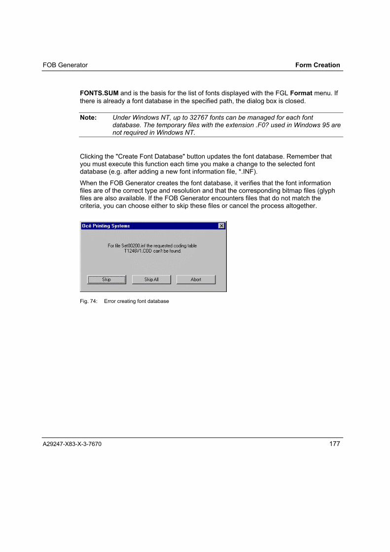
FOB Generator Form Creation
A29247-X83-X-3-7670 177
FONTS.SUM and is the basis for the list of fonts displayed with the FGL Format menu. Ifthere is already a font database in the specified path, the dialog box is closed.
Note: Under Windows NT, up to 32767 fonts can be managed for each fontdatabase. The temporary files with the extension .F0? used in Windows 95 arenot required in Windows NT.
Clicking the "Create Font Database" button updates the font database. Remember thatyou must execute this function each time you make a change to the selected fontdatabase (e.g. after adding a new font information file, *.INF).
When the FOB Generator creates the font database, it verifies that the font informationfiles are of the correct type and resolution and that the corresponding bitmap files (glyphfiles are also available. If the FOB Generator encounters files that do not match thecriteria, you can choose either to skip these files or cancel the process altogether.
Fig. 74: Error creating font database

Form Creation FOB Generator
178 A29247-X83-X-3-7670
Paper and Format Settings
Page Orientation:Use this option to specify whether the area of the form is to be a portrait or landscapepage.
Paper Size:
Fig. 75: FOB settings: paper size
Use this option to define the area covered by the form � the logical page. This may be thesame size as or smaller than the physical page.
You can choose from a range of standard formats. Choose the smallest possible size forthe form, since this gives you more scope for positioning it on the physical page. If none ofthe standard sizes are suitable, you can set a custom size. To do this, click the "Selectother size" button.
In the dialog box that opens, enter the size of paper you want to use. The setting youmake can then be selected and modified by choosing "Custom Size" in the list of formats.
Fig. 76: Specifying a custom size

FOB Generator Form Creation
A29247-X83-X-3-7670 179
Print Direction:
Fig. 77: FOB device settings: print direction
Use this option to indicate how the logical page defined by "Paper Size" and "PageOrientation" is to be placed or rotated on the physical page. You can thus rotate yourforms irrespective of the read direction of the variable data.
Output
Format:
Fig. 78: FOB settings: output format
Use this option to specify the format of the generated FOB after the execution of the WriteOverlay function. You can choose TRANS1, HEX or binary.
TRANS1 ASCII file, double-byte format, max. 80 positions, CRLF as logicalseparator, HDR records, suitable for ASCII transfer to host (like textfiles), with subsequent re-conversion using TRANSLIB program.
HEX ASCII file, double-byte format, max. 80 positions, CRLF as logicalseparator.
Binary Binary file, single-byte format, no CRLF.

Form Creation LCDS Generator
180 A29247-X83-X-3-7670
LCDS Generator
The LCDS Generator enables you to convert Form Creation forms to LCDS format (LCDS= Line Coded Data Stream). You can then use these forms as resources for XEROX®�printers and Prisma LCDS printing systems.
The LCDS Generator creates two LCDS resource files from an Form Creation form:
• <name>.FRM with a load module for the form;
• <name>.IMG with the image of the form
The LCDS Generator essentially consists of two components: printer driver and converter.In the printer driver, you make the settings relating to the printer on which you will beprinting the resources. The converter converts the forms directly from Form Creation toLCDS resources, using the printer settings you have selected, and creates the FRM andIMG files.
Text can be written with TrueType fonts or the available printer fonts. If you use printerfonts, bear in mind that you will need the font information files (*.INF). Text formatted withTrueType fonts will be compiled into the IMG file as a graphic. Text formatted with printerfonts will be output by way of the character codes.
Overview of LCDS format properties:
Fonts TrueTypePrinter fonts
Converted to graphicsReference (identification)
Graphics BitmapColour Black/whiteResolution 300 x 300 dpiOutputformat
FRM file (references IMG file)IMG (if graphic elements exist)
BinaryBinary

LCDS Generator Form Creation
A29247-X83-X-3-7670 181
LCDS SettingsWhen you generate resources with the LCDS Generator, you can specify the printresolution, the paper size and the orientation as your device settings.
Fig. 79: "OPS LCDS Properties" dialog box
The current parameters appear in blue. Changed parameters are shown in red. You candiscard all changes and restore the original settings by clicking the Undo ChangedOption button, provided you have not yet confirmed the dialog box with OK.
Click About OPS LCDS... to display details about the installed LCDS Generator software(version number, product number, series number, and version numbers of relevantsoftware modules).
Printer TypeThe data created with the LCDS Generator is not specific to any particular type of OPSprinter, so you can only choose the setting "ANY" here.

Form Creation LCDS Generator
182 A29247-X83-X-3-7670
Resolution:The only possible setting for the resolution of the destination printer is 300 x 300 dpi.
Fonts:The LCDS Generator supports both TrueType fonts � these are bitmapped in the form �and references to LCDS printer fonts ( .FNT). LCDS printer fonts can only be referencedin Form Creation if the corresponding INF files (font information files) are present in thefolder declared for this purpose (usually ...\FONTS\LCDS300).
Fig. 80: LCDS setting: fonts
Under "Fonts", you can set the path of the font database and select a different fontdatabase with the available fonts.
To select a different font database, click "Fonts <Path>". This opens a dialog box whereyou can select the folder containing the font information files (INF) for the bitmap fonts youwant to use.
Fig. 81: Dialog box for selecting font database
The folder must contain the font information in INF files, the conversion tables (COD files)and the font database (FONTS.SUM). Click OK to confirm the selected folder. If there is

LCDS Generator Form Creation
A29247-X83-X-3-7670 183
no font database in the folder, you are prompted to confirm that you want to generate anew one from the INF files using the corresponding conversion table (COD file).
Click "Create Fontdatabase..." to update the selected font folder. Bear in mind that youmust execute this update command following each change to the font database (e.g. eachtime you add a new font information file).
A special point to note with LCDS printers is that they cannot rotate printer fonts. For thisreason there are separate font files for each write direction. The folder for bitmap fontsalso has to contain a separate INF file (font information file) for each printer font in eachrotation.
When rotating the page or individual texts, Form Creation checks whether the affectedfonts are in fact available with the new orientation. If not, Form Creation issues a messageand a dialog box for selecting a font is opened. To prevent this happening, make sure youhave the fonts in all rotations for the typefaces you intend to use.
The following table shows which combination of page rotation (see section on writedirection) and text rotation (see Chapter � Setting the Text Rotation) requires whichversion of printer font:
Writedirectionon form
Textrotation
Required font Writedirectionon form
Textrotation
Required font
ACROSS 0 Portrait (P) BACK 0 Inverse Portrait (I)90 Landscape (L) 90 Inverse Landscape (J)180 Inverse Portrait (I) 180 Portrait (P)270 Inverse Landscape (J) 270 Landscape (L)
UP 0 Inverse Landscape (J) DOWN 0 Landscape (L)90 Portrait (P) 90 Inverse Portrait (I)180 Landscape (L) 180 Inverse Landscape (J)270 Inverse Portrait (I) 270 Portrait (P)
Paper and Format SettingsUse this section to specify the paper size for which the form can be used, and theorientation of the paper.
These settings define the area that will be made available in Form Creation for designingthe form. This area will be the white space in the Form Creation window. The LCDSGenerator integrates every form element in this space � i.e. on the paper � into the LCDSresource.

Form Creation LCDS Generator
184 A29247-X83-X-3-7670
Page Orientation:Here you can set the orientation with which the form will be placed on the paper: portraitor landscape.
Paper Size:You can choose any of three predefined paper sizes or define a custom size of your own.
Note: Before beginning to print, a Xerox printing system verifies that the paperloaded in the printer is actually of the format for which the resource wasgenerated. If the paper in the printing system is smaller than the size for whichthe resource was generated, printing cannot continue.
To define a custom paper size, click Select other Size. This opens the following dialogbox:
Fig. 82: Selecting a custom paper size
You can define a custom paper size up to 50.8 cm x 50.8 cm (20" x 20"). If you enter alarger value for the page length, the program alerts you that the length is being truncatedto the largest possible value. If you get the short and long sides mixed up, the programchanges them round for you � no message is issued telling you that this is being done.
You can enter the size in centimetres, inches or printer points (based on 300 dpi). Thevalue is in any case stored in printer points, and entries in centimetres or inches areconverted.
Print Direction:Use this option to set the direction in which the form is to be printed on the paper, definedin relation to the direction in which the paper runs through the printing system:
• Across

LCDS Generator Form Creation
A29247-X83-X-3-7670 185
• Up
• Back
• Down
Output Settings
Halftoning:The raster width can be set for graphics and shading . Raster Width (in lpi = lines perinch) is used to define the number of raster points in a specific area. With less preciseraster widths, multiple points are combined into one. This is useful if surfaces aredisplayed with irregular colouring (�cloudy�) at a high resolution.


Working with Form Creation Form Creation
A29247-X83-X-3-7670 187
Working with Form Creation
Setting Preferences for the Work Environment
Selecting the Interface Language
To change the language of the menus and help text, choose Sprache/Language in theOptions menu. This opens a dialog box where you can choose English or German. Thechange takes effect as soon as you confirm with OK.
Fig. 83: Choose Language dialog box
Note: The dialog boxes belonging to resource generators are not affected by thischange. Windows printer drivers use the language of the operating system.
Setting Rulers
As a guideline when you are designing forms, you can display a horizontal ruler acrossthe top of the window and a vertical ruler down the left side. To do this, choose Rulersfrom the View menu.

Form Creation Working with Form Creation
188 A29247-X83-X-3-7670
Fig. 84: Centimetre ruler with divisions of 10th units
You set the measuring unit and ruler divisions in the "Horizontal and vertical Rulers",dialog box, opened with the Ruler Settings command in the Options menu or by double-clicking the measuring unit field at the point where the rulers intersect (top left).
Fig. 85: "Horizontal and vertical Rulers" dialog box

Working with Form Creation Form Creation
A29247-X83-X-3-7670 189
The current settings can be stored as defaults using "Save as default" or can beoverwritten with default settings using "Reset to default".
When you choose "Align grid", the grid settings (see below) are automatically adapted tothe settings of the ruler. However, this does not change the default settings for the grid.
When you scroll the workspace with the scroll bars or alter the display using Full View orZoom In/Out, the ruler is automatically adjusted to the new screen display.
Note: The ruler is no more than an on-screen design aid � elements are stillconstructed according to the grid increments.
Adjusting the Grid
To ensure precision in forms designs, all the elements you construct are aligned to theincrements of a grid. The Show Grid command in the View menu lets you either show orhide the grid as appropriate.
Even when the grid is turned off, all elements are still constructed using the gridincrements you have defined.
Note: Having the grid displayed will slow down the screen refresh!
You can set different values for the x and y co-ordinates of the grid.
You set the unit and density of the grid with Grid Settings in the Options menu. Thisopens the "Grid for X- and Y-axis" dialog box.
Fig. 86: "Grid for X- and Y-axis" dialog box

Form Creation Working with Form Creation
190 A29247-X83-X-3-7670
The current settings can be stored as defaults using "Save as default" or can beoverwritten with default settings using "Reset to default".
Displaying the Crosshair
The crosshair is a fast and easy way of measuring positions in relation to the ruler. Youcan display a crosshair on the workspace with the tool pointers. The crosshair covers theentire workspace.
To display the crosshair, choose Long Mouse in the View menu. To turn the crosshairoff, choose the command again.
Displaying the Toolbox Field
The Form Creation tools can be launched by the commands in the Edit menu, bykeyboard shortcuts, and by clicking the buttons in the toolbox field.
You can display and hide the toolbox field by means of the Toolbox command (which is atoggle command) in the View menu.
Fig. 87: Toolbox field displayed

Working with Form Creation Form Creation
A29247-X83-X-3-7670 191
Displaying the Position Window
You can display a position window to tell you the exact position of an element selected onyour workspace. The windows shows the current X and Y co-ordinates of the top left andlower right corners of the element. Co-ordinates are always specified in the units of theset ruler.
You display and hide the position window using the Positions command in the Viewmenu.
Fig. 88: Position window
Settings for Formatting Forms and Generating Overlays
Your selection of a particular resource generator also determines which destinationprinting system you are creating the form for ("Printer Setup").
You can specify the format of the form in accordance with the possibilities provided by thegenerator ("Page Setup").
Choose Printer
To select the printing system for which you intend to create the form, choose ChoosePrinter from the File menu. The following dialog box opens:

Form Creation Working with Form Creation
192 A29247-X83-X-3-7670
Fig. 89: "Choose Printer for" dialog box
Click "Overlay And Formatting" here. This opens the "Choose Overlay Printer (used alsofor formatting)" dialog box:
Fig. 90: Dialog box for selecting an overlay printer

Working with Form Creation Form Creation
A29247-X83-X-3-7670 193
At present, the following generators are available for creating print resources with FormCreation:
Generator(printer driver)
Printer data format Resolution (dpi) CustomTone� Form
OPS SPDS AFPDS� compatible 240, 300, 600 X OverlayPagesegment
OPS PCL Macro PCL5e- 300, 600 X MacroOPS LCDS LCDS 300 FRM / IMG
* Cut sheet printer
Note: Select only a resource generator installed with Form Creation, and make surethe port for the print output is set to "File" (name: OPS <Format> on FILE☺ .Otherwise Form Creation will be unable to generate valid resources.
Proof Printing:The Proof Printing button opens a dialog box for the printer on which you intend to makeproof prints.
Fig. 91: "Choose Proof Printer" dialog box
After you have selected a printer, a Page Setup dialog box opens where you can makesettings such as the page rotation for the proof print.
Page Setup
To define the paper format and page orientation for the form, choose Page Setup fromthe File menu.

Form Creation Working with Form Creation
194 A29247-X83-X-3-7670
The command opens a dialog box for the selected resource generator, where you candefine settings for the current form. These settings � as opposed to the default settings �are valid only for the current form and are stored in the FRM file.
The settings in the printer-specific resource generator largely determine what type of printresource will be generated from the form design. Only two settings � Paperformat andPage Orientation � have a direct impact on the way the form is displayed on theworkspace.
Page Orientation defines whether the page will have a portrait or landscape orientation .
Paperformat defines the size of the workspace. Set the smallest possible format for yourform, since this gives you greater flexibility for integrating your form into print jobs withoutperformance loss.
To change the default values for all new forms, choose Printers in the Windows Controlpanel and open the setup menu for the resource generator concerned.
Detailed information about the settings you can make for each of the resource generatorsis provided in Chapter 5.
Defaults for Editing Elements
You can define default settings for the duplication and for colour presentation of elementson the workspace. These defaults remain valid until they are changed.
The defaults for editing elements only affect the way the Form Creation functions arehandled � they have no impact on the edited elements themselves.
Setting for Duplicating Elements
After selecting one or more elements with the pointer tool, you can choose Duplicate tocreate a copy of the elements . The copy is inserted into the form horizontally andvertically offset from the original.
To change the horizontal and vertical offset, choose Duplicate Settings from the Optionsmenu.

Working with Form Creation Form Creation
A29247-X83-X-3-7670 195
Fig. 92: "Duplicate Settings" dialog box
Enter the horizontal and vertical offsets of the duplicate in the dialog box fields. Positivevalues cause a shift to the right or down, negative values cause a shift to the left or up.
You can enter the shifts in centimetres, inches or points. To change the measuring unit,click the unit button.
The current settings can be stored as defaults using "Save as default" or can beoverwritten with default settings using "Reset to default".
Settings for Colour Mode
You can present colour elements of your forms in the Form Creation window either in theiroriginal colour or in CustomTone�.
CustomTone� is a special, custom-defined colour used on two-colour printing systems toemphasise particular elements.
CustomTone� can only be used in the SPDS and PCL data formats.While you are designing your form, you can get an idea of it will look like when printed bychoosing as the CustomTone� the colour that will later be used when the document isproduced. You should then also select "CustomTone�" for presenting colour elements inyour form.
You make the colour mode settings with the Colour Mode� command in the Optionsmenu. This opens the "Colour-Representation on Screen" dialog box, where you canselect either "CustomTone�" or "Display Element Colours" .

Form Creation Working with Form Creation
196 A29247-X83-X-3-7670
Fig. 93: "Colour-Representation on Screen" dialog box
If you do not choose a CustomTone�, the default colour will be a colour with an equalmix of red, green and blue. This appears grey on your screen.
To set the colour that will be used when the form goes into production, click the "SelectCustomTone�" button: this opens the "Select CustomTone�" dialog box.
Fig. 94: "Select CustomTone�" dialog box
The dialog box shows you a list of predefined CustomTones�. This list is empty if youhave not yet defined any.

Working with Form Creation Form Creation
A29247-X83-X-3-7670 197
Effect of the buttons in this dialog box:
Add ...: Adds a defined CustomTone� to the list. Form Creationopens the "Define CustomTone�" dialog box for a newCustomTone�
Modify ...: Changes the CustomTone� selected in the list. FormCreation opens the "Define CustomTone�" dialog box forthe colour selected in the list.
Delete: Removes the selected CustomTone� from the list,
Save as Default: Saves the selected CustomTone� as the default,
Reset to Default: Sets the selected CustomTone� as the default.
Clicking "Add�" or "Modify�" Opens the "Define CustomTone�" dialog box.
Fig. 95: Define "CustomTone�" dialog box"
When you have opened the dialog box by clicking "Add..." the field next to the "Color�"button shows you a predefined colour consisting of equal proportions of red, green andblue (beneath the colour field are the values 192, 192, 192 to indicate this) and thesaturation 0. The identifier field is empty.
When you have opened the dialog box by clicking "Modify�", the field next to the "Color"button shows you the colour you have selected, and beneath the field the proportions ofred, green and blue in the colour. The identifier field shows you the name assigned to theCustomTone�.

Form Creation Working with Form Creation
198 A29247-X83-X-3-7670
Fig. 96: "Define CustomTone�" dialog box, CustomTone� "petrol"
To define a new colour as a CustomTone�, or to change the selected CustomTone�,click the "Color..." button. This opens the "Color" dialog box.
Fig. 97: "Color" dialog box
This dialog box enables you to select one of the predefined colours or mix a shade of yourown. The select fields for the custom colour remain empty if you have not defined anyshades of your own.

Working with Form Creation Form Creation
A29247-X83-X-3-7670 199
To define a colour, click the "Define Custom Colors>>" button. This opens the "Color"dialog box, where you can mix your colour from a palette.
Fig. 98: "Color" dialog box for defining and adding a colour.
You can select a tone by clicking its position in the rainbow. The "Basic colors" field showsthe selected tone. You can make the tone lighter or darker by moving the black arrow onthe bar to the right of the field up or down.
The "Color:" field gives the definition of the tone selected in the rainbow as a numericvalue between 0 (extreme left of rainbow) to 239 (extreme right of rainbow).
The "Sat:" field gives the saturation of the tone as a numeric value between 0 (bottom ofrainbow) to 240 (top of rainbow).
The "Lum:" field gives the luminosity of the colour as a numeric value between 0 (dark =black) to 240 (light = white).
The fields "Red:", "Green:" and "Blue:" give the proportions of these colours in the tone asnumbers between 0 and 255 (0,0,0 =black, 255,255,255 = white).
You can also define a tone by entering the numeric values in these fields. Bear in mindthat changing the saturation or luminosity will alter the proportions of red, green and blue.
Click the "Add to Custom Colors" button to confirm the defined tone and add it to the setof user-defined colours.
Click "OK" to close the "Color" dialog box. The colour in the selected field is thenpresented as a CustomTone� in the "Define CustomTone�" dialog box.

Form Creation Working with Form Creation
200 A29247-X83-X-3-7670
In the "Identifier:" field in this dialog box, enter the name you want to assign to the newCustomTone�. The colour will be entered under this name in the list of predefinedCustomTones� in the "Select CustomTone�" dialog box.
Click "OK" to return to the "Select CustomTone�" dialog box. You will then see the newCustomTone� in the list of predefined CustomTones�. If you now select one of theseand confirm the dialog box with OK, the "Colour-Representation on Screen" dialog box willre-open, containing the selected colour and its assigned name.
Fig. 99: "Colour-Representation on Screen" dialog box with CustomTone� "petrol"
With this setting, all colour elements in your form will be displayed with the colour youhave defined as the CustomTone�.
This setting only affects the way your forms are presented in the Form Creation editor. Ithas no impact on the elements themselves, the form and the print resource you generatefrom the form. You can change the setting at any time. When you switch fromCustomTone� presentation to "Display Element Colours", the elements are shown in thecolour which they were assigned in the design of the form (using Element Colour in theFormat menu).

Working with Form Creation Form Creation
A29247-X83-X-3-7670 201
Defaults for Formatting Elements
You can define a range of default format settings for the elements of your form. These areapplied to all the elements you create or insert. You can change the settings at any time �the elements you have already created retain the settings they already have.
You can change the formatting of existing objects. To do this, click the elements and thenchange the settings.
Line Settings
You can set the width and type of line which Form Creation draws in lines, ellipses, boxes,polylines and read lines.
If you open the dialog box without first selecting a graphic element, the settings apply toall elements with lines which you subsequently create. If you select a graphic elementbefore choosing the command, the settings apply only to the selected element.
You define the settings for lines in the Graphic menu.
Fig. 100: Graphic menu
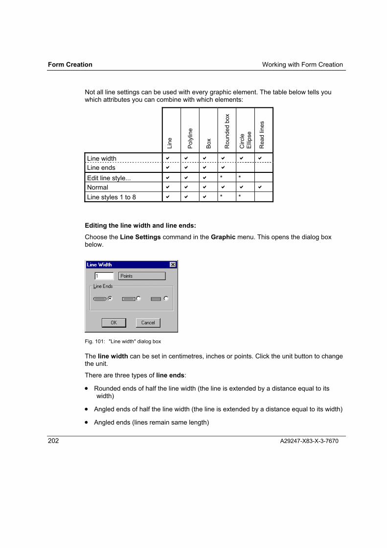
Form Creation Working with Form Creation
202 A29247-X83-X-3-7670
Not all line settings can be used with every graphic element. The table below tells youwhich attributes you can combine with which elements:
Line
Poly
line
Box
Rou
nded
box
Circ
leEl
lipse
Rea
d lin
es
Line width a a a a a a
Line ends a a a a
Edit line style... a a a * *Normal a a a a a a
Line styles 1 to 8 a a a * *
Editing the line width and line ends:Choose the Line Settings command in the Graphic menu. This opens the dialog boxbelow.
Fig. 101: "Line width" dialog box
The line width can be set in centimetres, inches or points. Click the unit button to changethe unit.
There are three types of line ends:
• Rounded ends of half the line width (the line is extended by a distance equal to itswidth)
• Angled ends of half the line width (the line is extended by a distance equal to its width)
• Angled ends (lines remain same length)

Working with Form Creation Form Creation
A29247-X83-X-3-7670 203
Selecting the line style:Use the Graphic menu to select the line style "Normal" or one of the eight special styles.
In Windows NT and Windows 2000 the line style is valid for all the elements drawn withgraphic tools, apart from read lines.
In Windows 95 the line style is valid for all the elements drawn with graphic tools, apartfrom read lines, ellipses and rounded boxes.
You can customise line styles 1 to 8 using the Edit Line Types command.
Editing line styles:Form Creation lets you use up to eight editable types of line (plus the solid line type) ineach form. You can also load a set of line styles from a file or save a set of types of lateruse.
Choose Edit Line Types in the Graphic menu to open the following dialog box:
Fig. 102: "Edit Linestyle" dialog box
Under "Style", select the type of line you want to edit.
The "Example" field shows you how the line would be drawn with each of the three lineends.
You have a 16-dot field available for editing. You can fill or delete fields by clicking them.The editing field represents a line section of around 1.5 cm in length, i.e. the pattern youdefine here will be repeated every 1.5 cm to form the line. If you fill all the dots, you createa solid line.
You can also save sets of eight line styles as an FRL file, separate from your forms. To dothis, click "Save to�" and specify the file to receive the data.

Form Creation Working with Form Creation
204 A29247-X83-X-3-7670
Use "Load from..." to load a set of line styles into Form Creation from a file.
Notes:
• When you save a form with the Save or Save as command in the File menu, the linestyle definitions are also saved in the FRM file. They are restored the next time youload the form.
• When you load an FRM file with custom line definitions, these definitions are used byForm Creation.
• The changed settings also apply to new form files.
• If you modify line styles or load a line style file, this will immediately have an effect onthe appearance of a form.
• You cannot change the Normal line style.
• Form Creation ships with the file STD.FRL, containing the standard line styles. Re-loadthis file if the default line definitions are destroyed for any reason.
Setting the Corners
You can set the degree of rounding for the corners of boxes.
When you make settings without first selecting a rectangle, the corner settings you makein the dialog box apply to all rectangles you subsequently create. When you select arectangle first, you can adjust the radius of each corner of this rectangle, setting adifferent value for each corner, even if the box was originally drawn with right angles.
Choose Corners from the Graphic menu to open the "Rounded Rectangle" dialog box,where you set the rounding of the four corners of a rectangle. Each corner can have adifferent value. You can also indicate which corners and edges are to be drawn visibly.

Working with Form Creation Form Creation
A29247-X83-X-3-7670 205
Fig. 103: Rounded Rectangle dialog box
You can make the following settings for drawing rounded rectangles:
Units: Measuring unit for specifying radii: centimetres/inches/points;click the button to change to the measuring unit of your choice.
All corners identical Check this option if you want the rounding value for the upperleft corner to apply to all four corners
x- and y-radius identical Check this option to draw corners as even quarter-circles.
Upper left corner The defined corner is visible only if this option is checked.
X-Radius Radius of corner in x-direction. The value is given in the setmeasuring unit.The radius can be no more than half the length of the relevantside of the rectangle.
Y-Radius Radius of corner in y-direction. The value is given in the setmeasuring unit.The radius can be no more than half the length of the relevantside of the rectangle.You cannot enter a value here if you have checked the "x- andy-radius identical" option.
Upper right corner The defined corner is visible only if this option is checked.

Form Creation Working with Form Creation
206 A29247-X83-X-3-7670
X-Radius Radius of corner in x-direction. The value is given in the setmeasuring unit.The radius can be no more than half the length of the relevantside of the rectangle.You cannot enter a value here if you have checked the "Allcorners identical" option.
Y-Radius Radius of corner in y-direction. The value is given in the setmeasuring unit.The radius can be no more than half the length of the relevantside of the rectangle.You cannot enter a value here if you have checked the "Allcorners identical" option and "x- and y-radius identical" option.
Lower left corner The defined corner is visible only if this option is checked.
x-Radius Radius of corner in x-direction. The value is given in the setmeasuring unit.The radius can be no more than half the length of the relevantside of the rectangle.You cannot enter a value here if you have checked the "Allcorners identical" option.
Y-Radius Radius of corner in y-direction. The value is given in the setmeasuring unit.The radius can be no more than half the length of the relevantside of the rectangle.You cannot enter a value here if you have checked the "Allcorners identical" option and "x- and y-radius identical" option.
Lower right corner The defined corner is visible only if this option is checked.
X-Radius Radius of corner in x-direction. The value is given in the setmeasuring unit.The radius can be no more than half the length of the relevantside of the rectangle.You cannot enter a value here if you have checked the "Allcorners identical" option.
Y-Radius Radius of corner in y-direction. The value is given in the setmeasuring unit.The radius can be no more than half the length of the relevantside of the rectangle.You cannot enter a value here if you have checked the "Allcorners identical" option and "x- and y-radius identical" option.
Top link line Check the box here if you want this line linking the two cornerradii to be visible.

Working with Form Creation Form Creation
A29247-X83-X-3-7670 207
Left link line Check the box here if you want this line linking the two cornerradii to be visible.
Right link line Check the box here if you want this line linking the two cornerradii to be visible.
Lower link line Check the box here if you want this line linking the two cornerradii to be visible.
OK Confirm settings and close dialog box.
Cancel Discard settings and close dialog box.
Setting the Fill Pattern
You can assign a fill pattern to spatial elements and bitmaps. A pattern can be anywherebetween white and black, specified in terms of a percentage value. You can also loadpatterns from files.
You select and define the type of fill pattern via the Fill menu.
Fig. 104: Fill menu
If you choose the command without selecting a fillable element, the setting you make hereis valid for all elements you subsequently draw with the Form Creation tools.
You can also select an element first � the pattern you then choose is assigned just to theselected elements. The default pattern settings are not changed.
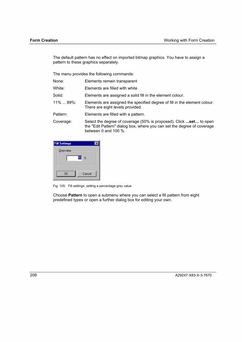
Form Creation Working with Form Creation
208 A29247-X83-X-3-7670
The default pattern has no effect on imported bitmap graphics. You have to assign apattern to these graphics separately.
The menu provides the following commands:
None: Elements remain transparent
White: Elements are filled with white
Solid: Elements are assigned a solid fill in the element colour.
11% ... 89%: Elements are assigned the specified degree of fill in the element colour.There are eight levels provided.
Pattern: Elements are filled with a pattern.
Coverage: Select the degree of coverage (50% is proposed). Click ...set� to openthe "Edit Pattern" dialog box, where you can set the degree of coveragebetween 0 and 100 %.
Fig. 105: Fill settings: setting a percentage grey value
Choose Pattern to open a submenu where you can select a fill pattern from eightpredefined types or open a further dialog box for editing your own.

Working with Form Creation Form Creation
A29247-X83-X-3-7670 209
Fig. 106: Selecting a fill pattern
Click edit� to open the "Edit Fillpatterns" dialog box.
Fig. 107: The "Edit fillpatterns" dialog box
Under "Fill", select the pattern you want to edit. The "Example" field shows you how thepattern would appear on the form.
Form Creation Working with Form Creation
210 A29247-X83-X-3-7670
You have an 8x8 dot field available for editing. You can fill or delete fields by clickingthem. The editing field represents a "tile", which will be repeated to fill the patternedspace. If you fill all the dots, you create a solid-fill area.
You can also save sets of eight patterns as an FRP file, separate from your forms. To dothis, click "Save to" and specify the file to receive the data.
Use "Load from..." to load a set of patterns into Form Creation from a file.
Notes:• When you save a form with the Save or Save as command in the File menu, the
patterns are also saved in the FRM file. They are restored the next time you load theform.
• When you load an FRM file with custom pattern definitions, these definitions are usedby Form Creation.
• The changed settings also apply to new form files.
• If you modify patterns or load a pattern file, this will immediately have an effect on theappearance of a form.
• Form Creation ships with the file STD.FRP, containing the standard patterns. Re-loadthis file if the default pattern definitions are destroyed for any reason.
• The way patterns are presented on the screen and on proof prints depends largely onthe features of the printer and monitor. There can therefore be slight differencesbetween a proof print and a printout made on an Océ printing system.
Settings for Margins and Rotation
You can make the following default settings for placing text on the form as you design it:
• How wide the margins are to be between the text and the edge of the element,
• How the text is to be vertically aligned,
• What direction the text is to be rotated.
To make these settings, choose Margins & Rotation from the Format menu. This opensthe "Format Margins & Rotation" dialog box. Bear in mind that you must not have the texttool selected when you perform this action.

Working with Form Creation Form Creation
A29247-X83-X-3-7670 211
Fig. 108: The "Format Margins & Rotation" dialog box
You can set the margins in centimetres, inches or points. Click the "Units" button to switchthe unit (1 inch = 2.54 cm = 72 points).
You can specify different values for the top, left, bottom and right margins. Enter thevalues directly into the fields. The largest distance you can enter is 1637 points.
The text can be aligned vertically to three positions: top, centre or bottom. When youselect top or bottom, the text is aligned to the top or bottom edge, leaving a space equal tothe specified margin. When you select Center the text is centred between the top andbottom edges.
Text can be rotated by 0°,90°,180° and 270°.
Only the text is rotated � not the text field. You may have to adapt the size of the elementto the new placement of the text.
The default settings you make for margins and rotation are valid for all text elements yousubsequently add to your form using the text tool. You can change these default settingsat any time, but you must first ensure that there is no text element selected on the form.
You can change the margins and rotation of a specific text element by first selecting it withthe pointer tool and then choosing the Margins & Rotation command from the Formatmenu. The default settings for new text elements remain unchanged.

Form Creation Working with Form Creation
212 A29247-X83-X-3-7670
Settings for Formatting Paragraphs
You can make the following default settings for the paragraphs of text you add to yourform:
• Typeface, font style and size,
• Line spacing,
• Indents,
• Horizontal alignment,
• Foreground colour,
• Background colour
To make these settings, choose Paragraph from the Format menu. This opens the"Format Paragraph" dialog box. Bear in mind that you must not have the text tool selectedwhen you perform this action.

Working with Form Creation Form Creation
A29247-X83-X-3-7670 213
Fig. 109: "Format Paragraph" dialog box
Fonts:You can select the printer font and point size from an alphabetical list. When you haveselected a font, the "Weight" and "Size" lists show you which styles(Normal/Italic/Bold/Bold Italic) and sizes are available. You can only select sizes andweights in this manner if the font is a scalable printer font.
Under "other Size" you can specify a non-listed size of TrueType or scalable printer font.
Minimum size: 2.54 points
Maximum size: 72 points

Form Creation Working with Form Creation
214 A29247-X83-X-3-7670
The specimen field shows you the appearance of the selected font. Beneath the specimenfield is an entry denoting the type of font being displayed (TrueType or printer font), andwhether it is monospaced or proportional. When you are using a monospaced printer font,the character width (CPI) is shown. For printer fonts, you also see the name of the fontINF file.
Note: For presenting text on the screen, Form Creation uses the TrueType font thatmost closely resembles the printer font you have selected. The resultsobtained with proof prints depend greatly on the capabilities of your printer andthe fonts available for it.
Spacing:The spacing above and below a paragraph can be defined as an absolute value incentimetres, inches or points.
You can define the line spacing (line increment)
• as a percentage of the point size
• as an absolute value in centimetres, inches or points
• in lines per inch (LPI)
The setting "relative" as a percentage of the line spacing or "absolute" is only possible ifyou have not checked the "Lines per Inch" box.
Indent:You can indent the lines in a paragraph. You can enter different values for the first lineand following lines.
When you are working with condensed type, you have to distinguish betweenmonospaced and proportional fonts.
Monospaced fonts: you can enter the character increments either as an absolute value oras a percentage of the character width.
Proportional fonts: you have to enter an absolute value. However, you can elect to handlecondensed proportional fonts in the same way as monospaced fonts. To do this, checkthe "monospaced" option. This has the effect of making all the characters the same width(the largest character in the proportional font is used as the basis). You can then enter thecharacter increment for condensed type as a percentage of the character width.

Working with Form Creation Form Creation
A29247-X83-X-3-7670 215
Horizontal alignment:For the horizontal alignment of a paragraph, you can choose between:
• Left
• Right
• Centred
• Justified
Foreground colour:The foreground colour enables you to define the colour of the text (i.e. type). If you do notdefine a different foreground colour, the text is shown in the colour you have selected forelements.
On the design, the text is shown in the element colour you select with Colour Mode...(Options menu) or � if you have not assigned black or white � in the selectedCustomTone�.
Background colour:The background colour is used to fill the text field.. "None" is equivalent to "white". On thedesign, the background is shown in the colour you select with Colour Mode... (Optionsmenu) or � if you have not assigned black or white � in the selected CustomTone�.
You can alter the paragraph formatting of text elements after they have been created. Todo this, select the elements you want to modify before opening the "Format Paragraph"dialog box. Changing elements in this way has no impact on the default settings applied totext elements.
Setting the Element Colour
You can define the colour that will be used to present elements on your form design.
To do this, choose Element Colour in the Format menu. This opens the "Format Object"dialog box containing just one tab: "Color".
In order to set the default element colour, you must make sure the pointer tool is notactive and you do not have an element selected.

Form Creation Working with Form Creation
216 A29247-X83-X-3-7670
Fig. 110: Default setting for object colour
The specimen field shows the set colour. The list below "Color" contain seven colours,plus black, a CustomTone� (if defined) and white. Select the colour you want to use.
All elements you subsequently place on the workspace using the editor tools will beassigned the colour you select here.
The editor presents the colours either in the selected object colour or in CustomTone�,depending on what setting you make with the Colour Mode command in the Optionsmenu.
You can alter the colour of an existing element by selecting the element before you openthe dialog box for setting the colour. This change has no impact on the default elementcolour.

Working with Form Creation Form Creation
A29247-X83-X-3-7670 217
Creating, Opening and Saving Forms
New Form
To create a form, choose New from the File menu.
The new form deletes the current form from your PC memory. If you have not yet savedthe changes to the current form, you are asked if your want to do so before the new formis created.
Fig. 111: Creating a new form
All definitions are reset to default values. The size of the workspace and the rotation of theform correspond to the page setup for the resource generator that is currently selected.
Opening a Form
To open a form for further editing, choose Open from the File menu. This opens a dialogbox where you can choose the FRM file you want to work with.
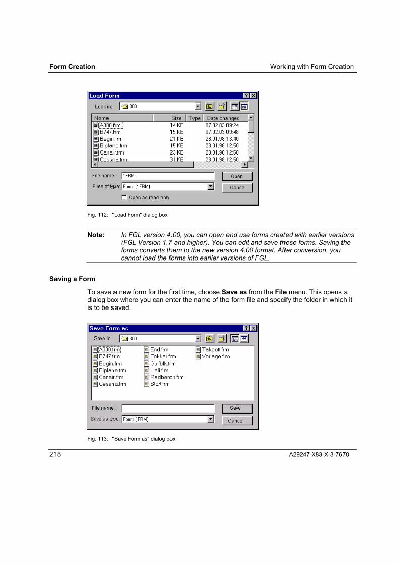
Form Creation Working with Form Creation
218 A29247-X83-X-3-7670
Fig. 112: "Load Form" dialog box
Note: In FGL version 4.00, you can open and use forms created with earlier versions(FGL Version 1.7 and higher). You can edit and save these forms. Saving theforms converts them to the new version 4.00 format. After conversion, youcannot load the forms into earlier versions of FGL.
Saving a Form
To save a new form for the first time, choose Save as from the File menu. This opens adialog box where you can enter the name of the form file and specify the folder in which itis to be saved.
Fig. 113: "Save Form as" dialog box

Working with Form Creation Form Creation
A29247-X83-X-3-7670 219
You can also use Save as to save an existing form under a new name or in a differentfolder.
To save an existing form again under the same name in the same folder, you shouldchoose Save from the File menu.
Save overwrites a form with the same name. No warning message is issued.
When creating or editing large (complex) forms, you should always save your workregularly.
At regular intervals, Form Creation saves the form you are working on to a temporary file.Should your system terminate abnormally for any reason, Form Creation automaticallyopens this temporary file when you restart your system. You then have to save the fileusing the Save as function, as you would with a new file.
The Abandon command in the File menu discards all changes made to the current formsince it was last saved. Form Creation then re-opens the form as it was at the start of yourwork session.

Form Creation Working with Form Creation
220 A29247-X83-X-3-7670
Properties of Forms
The Properties command in the File menu opens the "Properties" dialog box, where youcan enter or view comments about the current form. The comment is stored in the FRMfile, but not in the generated print resource.
Fig. 114: "Properties" dialog box
Comments may be several lines long. Lines are automatically wrapped. You can use thefollowing text editing commands:
Ctrl + Return (↵) : Line wrapDel : DeleteCtrl + X : CutCtrl + C : CopyCtrl + V : Paste
A comment can be up to 16 Kbytes long (around 200 lines of text). If the comment isshorter, only the required amount of storage is used.

Working with Form Creation Form Creation
A29247-X83-X-3-7670 221
Importing Forms
The program Form Import enables you to import electronic forms in other formats intoForm Creation for editing.
You launch Form Import with the command Import External Form in the File menu. Thecommand is not available (greyed) if the program is not installed on your system.
Loading and Displaying Background Images
To assist you in designing your form you can display one or more graphic objects astemplates � background images � on your workspace. These images are not compiledinto the print resource.
Use Background Image� in the Options menu to open the "Background Image" dialogbox. Here, you can load and remove background images, define their position on theworkspace and define the presentation size (width and height) and colour.
Fig. 115: "Background Image" dialog box
Click "Load�" to open the "Open background image file" dialog box, in which you canselect which image file you want to open. You can load background images from files inany of the standard graphic formats.

Form Creation Working with Form Creation
222 A29247-X83-X-3-7670
Fig. 116: "Open background image file" dialog box
You turn the display of the background mage on and off using the Background Imagecommand (a toggle command) in the View menu.
Background images are particularly useful when you want to match up several forms forcombining and printing on the same page. To do this, generate the form you want tocheck as a metafile (see Chapter Generating Print Resources) and load the form from theWMF or EMF file for displaying as a background image. This will help you design acorresponding form.

Working with Form Creation Form Creation
A29247-X83-X-3-7670 223
Working with the Form Creation Tools
You can activate the Form Creation tools in various ways:
• Via the buttons in the toolbox field,
• Via the Tool command in the Edit menu,
• Via keyboard shortcuts
When you select a tool, the cursor takes on the specific shape for the tool concerned.
The current position of a tool pointer (apart from the pointer itself) is shown in the "Lowerright" fields of the "Position" window, which you can display using the Positions commandin the View menu. As soon as you release the left mouse button, the current position isentered in the "Upper left" fields.
Fig. 117: Position of tool pointer

Form Creation Working with Form Creation
224 A29247-X83-X-3-7670
The table below states which buttons and keyboard shortcuts activate each of the tools,what action the tools perform, and what shape the cursor takes on. .
Tool Button Keyboardshortcut
Cursor Task
Pointer Crtl+1 Select elements
Box Crtl+3 Draw box
Roundedbox Crtl+4 Draw box with rounded
corners
Ellipse Crtl+5 Draw circle or ellipse
Line Crtl+6 Draw line
Polyline Crtl+Shift+1 Draw polyline
Read lines Crtl+7 Create block of read lines
Paragraph Crtl+2 Select paragraph of text
Text Crtl+8 Enter text
Object Crtl+9 Create OLE object
WordDocument Crtl+0 Create Word object

Working with Form Creation Form Creation
A29247-X83-X-3-7670 225
Drawing Boxes
The following tools are available for drawing boxes:.
Box with right-angled corners (Ctrl + 3)
Box with rounded corners; corner radius can be custom-defined Ctrl + 4)
Click the position on the workspace where you want to place the start point for the newelement. Keeping the mouse button pressed, drag the rectangle or square to the requiredsize. Form Creation operates a "snap" function and automatically aligns the element to thenext grid line, no matter whether the grid is displayed or not.
The box is drawn with the lines, fill pattern and element colour you have specified as yourdefaults. Boxes with rounded corners are drawn with the default corner radius.
To make a custom setting for the lines, fill patterns and element colour, select the box withthe arrow and define your settings as described in Chapter �Defaults for FormattingElements�. A double-click on a selected box opens a dialog box where you can makesettings for the corners (see Chapter �Setting the Corners�).
To resize a box or move it to a different position on your form, select it with the pointer.You will then see "handles" at the corners and on the sides of the boxes. If you point toone of the handles, a double-headed arrow appears to indicate the directions in which youcan move or change the box: left and right along the vertical sides, and up and downalong the horizontal sides. On the corners, the direction is diagonal.
If you point elsewhere inside the bounds of the element, a cross is shown. You can thendrag the box to a new position by pressing and holding the left mouse button.
Drawing Circles and Ellipses
The following tool is used for drawing circles and ellipses.
Ellipse (Crtl + 5)
Click the position on the workspace where you want to place the start point for the newelement. Keeping the mouse button pressed, drag the ellipse or circle to the required size.Form Creation automatically aligns the element to the next grid line.
The element is drawn with the lines, fill pattern and element colour you have specified asyour defaults.
To make a custom setting for the lines, fill patterns and element colour, select the elementwith the arrow and define your settings as described in Chapter 6.1.3.
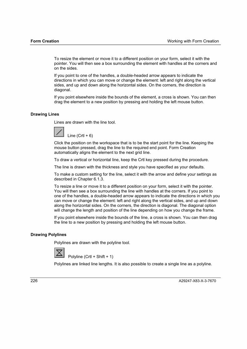
Form Creation Working with Form Creation
226 A29247-X83-X-3-7670
To resize the element or move it to a different position on your form, select it with thepointer. You will then see a box surrounding the element with handles at the corners andon the sides.
If you point to one of the handles, a double-headed arrow appears to indicate thedirections in which you can move or change the element: left and right along the verticalsides, and up and down along the horizontal sides. On the corners, the direction isdiagonal.
If you point elsewhere inside the bounds of the element, a cross is shown. You can thendrag the element to a new position by pressing and holding the left mouse button.
Drawing Lines
Lines are drawn with the line tool.
Line (Crtl + 6)
Click the position on the workspace that is to be the start point for the line. Keeping themouse button pressed, drag the line to the required end point. Form Creationautomatically aligns the element to the next grid line.
To draw a vertical or horizontal line, keep the Crtl key pressed during the procedure.
The line is drawn with the thickness and style you have specified as your defaults.
To make a custom setting for the line, select it with the arrow and define your settings asdescribed in Chapter 6.1.3.
To resize a line or move it to a different position on your form, select it with the pointer.You will then see a box surrounding the line with handles at the corners. If you point toone of the handles, a double-headed arrow appears to indicate the directions in which youcan move or change the element: left and right along the vertical sides, and up and downalong the horizontal sides. On the corners, the direction is diagonal. The diagonal optionwill change the length and position of the line depending on how you change the frame.
If you point elsewhere inside the bounds of the line, a cross is shown. You can then dragthe line to a new position by pressing and holding the left mouse button.
Drawing Polylines
Polylines are drawn with the polyline tool.
Polyline (Crtl + Shift + 1)
Polylines are linked line lengths. It is also possible to create a single line as a polyline.

Working with Form Creation Form Creation
A29247-X83-X-3-7670 227
Polylines can be open or closed. In a closed polyline, the end point of the last line meetsup with the start point of the first. A closed polyline consists of at least three lines.
To draw a polyline, proceed as follows:
⇒ Select the polyline tool. The mouse pointer turns into a polyline symbol.
⇒ Draw the first line: keep the mouse button pressed and drag the polyline pointer fromthe start to end of the desired line. Then release the mouse button.
⇒ Draw the next line. Click the left mouse button where you want the second line to end.A line is then drawn from the end point of the first line to the end point you have justclicked. Repeat until you have drawn an element with the shape you want.
⇒ Finish your polyline by exiting the last end point and double-clicking anywhere on theworkspace. To create a closed polygon, keep the Crtl key pressed while you do this.
You also close the polygon by selecting a different tool.
You can change the size and shape of an existing polyline.
To change the size
⇒ Click the polyline once with the pointer tool � a box with handles appears round thepolygon
⇒ Drag the handles on the box in the direction you wish.
To change the shape
⇒ Double-click the polyline with the pointer tool � handles appear on all the start andend points of the lines
⇒ Drag the markers one-by-one in the desired direction
⇒ To set additional corner points, press and hold the Shift key and click on a line in thepolyline. A new corner point is set at this position,
⇒ Delete corner points by holding the Shift key pressed while you click the points youwant to remove.
Open polylines with at least two lines and closed polylines can be filled with a fill pattern.There are two fill modes for polylines with several intersecting lines: alternate andwinding.
To edit a polyline, select it and then choose Object in the Format menu. This opens the"Polyline" dialog box. Here, you can assign the polyline type (open or closed) and fillmode (alternate or winding.

Form Creation Working with Form Creation
228 A29247-X83-X-3-7670
Fig. 118: "Polyline" dialog box
If you choose "Closed" for the type of polyline, the polyline you have selected is closed if itis open. If necessary, Form Creation draws an additional line.
In "Alternate" fill mode, multiple areas in a polyline of intersecting lines are alternatelyfilled and left empty. In "Winding" mode, the fill patterns are wound round the lines in readdirection. Depending on the direction in which the lines run, certain fields in overlappingpolylines can also remain unfilled even if "Winding" is selected (see examples).
Polylines are drawn with the lines, fill pattern and element colour you have specified asyour defaults. To make a custom setting for the lines, fill patterns and element colour,select the polyline with the arrow and define your settings as described in Chapter 6.1.3.
Examples of polylines:
1: Open polyline, filled.
2: Polyline drawn open; closed by formatting; filled.
3: Polyline drawn closed; not filled.
4: Polyline with intersecting lines; fill mode alternate.
5: Polyline with intersecting lines; fill mode winding.
6: Polyline with intersecting lines; fill mode alternate.
7: Polyline with intersecting lines; fill mode winding.

Working with Form Creation Form Creation
A29247-X83-X-3-7670 229
Drawing Read Lines
Computer forms often need read lines. Form Creation's read line tool enables you to drawthese lines in one easy step.
Read lines (Crtl + 7)
Select the tool and click the starting position. Hold the mouse button and drag the box tothe end position. Then release the button. The "Text Fields Settings" dialog box thenopens, in which you enter the necessary values.
Fig. 119: Dialog box for setting read line parameters
You can make the following settings:
Gray every...: Number of lines between one greyed line and the next
Part into ...: Number of read lines in text box
Fill...: Fill pattern for shading lines
The non-shaded lines are back-set with the pattern selected with Fill, the lines have thewidth you have defined as your default line thickness.

Form Creation Working with Form Creation
230 A29247-X83-X-3-7670
Editing read lines:Double-click the element with the read lines. This opens the dialog box for you to makeyour changes.
Read lines are drawn with the lines, fill pattern and element colour you have specified asyour defaults. To make a custom setting for the lines, fill patterns and element colour,select the field with the arrow and define your settings as described in Chapter 6.1.3.
Examples of read lines:
Part into 8 Part into 8 Part into 8Gray every 2 Gray every 2 Gray every 2Fill white Fill white 1 Fill white
Fill menu: Fill menu: Fill menu:None None Fill 2
Part into 8 Part into 8 Part into 8Gray every 2 Gray every 4 Gray every 4Fill 1 Fill 1 Fill white
Fill menu: Fill menu: Fill menu:Fill 2 None Fill 2

Working with Form Creation Form Creation
A29247-X83-X-3-7670 231
Entering Text
Use the text tool to enter and edit text elements. You can type the text anywhere on yourform or enter it in a closed element (box, box with rounded corners, circle or ellipse; notpolylines).
Text (Crtl + 8)
Text without surrounding element:If you want to type text at a particular place on the form, click the text pointer where youwant the text to begin. Type your text and press Shift+Return at the end of the first line.This automatically sets your word-wrap length and all subsequent text that you enter willwrap at this point. All the text up to the point where you press Return is part of aparagraph. You begin a new paragraph with Return (↵).
You conclude the text element by selecting a different tool or command or by clickingelsewhere on the form. Form Creation will then create a text field. By default, the text fieldis transparent (no fill pattern) and has no frame. You can change these settings, and canalso change field's position and size.
When you add text to an existing element, you have to enlarge the text field manually. Thesection of text that does not fit in the field will not be shown on the form. Use the Checkfor clipped text command in the Options menu to have Form Creation check your formfor objects containing clipped text.
Text in a surrounding element:To enter text in a box, circle or similar, click the text pointer in the element. The line lengthis adjusted to the width of the element; for circles, ellipses and boxes with roundedcorners, the line width is determined by the element's bounding box.
You can enter as many paragraphs as you wish in an element. As with free text, only thetext that fits in the element is actually shown on the form. Use the Check for clipped textcommand in the Options menu to have Form Creation check your form for objectscontaining clipped text.
Texts are assigned the default settings for formatting options (font, font style and size, linespacing, indents, horizontal alignment, margins and rotation, and element colour). Tochange these settings for a particular text, select the text and make your settings asdescribed in Chapter 6.1.4.

Form Creation Working with Form Creation
232 A29247-X83-X-3-7670
Formatting text elements:To format entire text elements, click the element and choose the appropriate commandfrom the Format menu. You can:
• Define the margins and rotation of the entire text in the element.
• Define a single paragraph formatting of all the paragraphs in the element.
• Assign the text a colour corresponding to the selected CustomTone�.
Formatting paragraphsTo format one or more paragraphs in an element, first select the paragraph(s) with theparagraph tool.
Paragraph (Crtl + 2)
Using the commands in the Format menu, you can:
• Format the selected paragraphs (see Chapter Settings for Formatting Paragraphs),
• Merge the selected paragraphs into a single one (see Chapter Merging Paragraphs).
Formatting characters:To format individual characters, select them with the text cursor and choose Character inthe Format menu. This opens the "Format Character" dialog box:

Working with Form Creation Form Creation
A29247-X83-X-3-7670 233
Fig. 120: "Format Character" dialog box
In this dialog box, you can select the printer font and point size from an alphabetical list.Printer fonts are available in certain sizes; for TrueType fonts you have to select one size.If the font is monospaced (non proportional), you are also shown the CPI (Characters perInch) value.
Selected characters can be underlined. The position of the underscore is defined in theINF file for printer fonts, and in the TTF file for TrueType fonts.
You can also assign the superscript or subscript attribute to selected words or characters.The value Shift Baseline determines the size of the shift; the prefix determines thedirection. The plus symbol "+" causes a shift up, the minus symbol "-" a shift down.
The superscript and subscript can be specified in points, centimetres or inches.

Form Creation Working with Form Creation
234 A29247-X83-X-3-7670
Editing Text
The text tool enables you to edit existing text elements using standard text editingfunctions.
Click the text tool pointer in the text to position the cursor.
Moving the cursor:Use the cursor keys (&$'() or the following keyboard shortcuts to move the cursor inthe text.
Keyboard shortcut: sends cursor to:
Home Start of line
End End of line
Crtl + Home Start of first paragraph in element
Crtl + End End of last paragraph in element
Crtl + & Start of current word
Crtl + $ Start of next word
Crtl + ' (or PgUp) Start of current (or previous) paragraph
Crtl + ( (or PgDn) Start of next paragraph
When you move the cursor using a keyboard shortcut and press the Shift key at the sametime, the text between the original and new cursor positions is selected.
Selecting text:You select text in the normal way: keep the left mouse button pressed while you drag thepointer across the text (characters, words or paragraphs).
Double-clicking in a word selects the entire word.
When you move the cursor using a keyboard shortcut (see above) and press the Shift keyat the same time, the text between the original and new cursor positions is selected.

Working with Form Creation Form Creation
A29247-X83-X-3-7670 235
Editing text:You can edit selected text with the usual functions:
Copy (Crtl + C)
Cut (Crtl + X)
Paste (Crtl + V)
Delete (Del)
You can execute these functions via keyboard shortcuts or by choosing the commandsfrom the Edit menu.
When you select a section and key in or paste new text, the selected section isautomatically overwritten. To insert additional text (and leave the old text in place),position the cursor to where you want to begin inserting, and do not select any text.
The Undelete function cannot be used to cancel a text editing operation.
Merging Text
Use the Merge Text command to combine multiple text elements in a form into a singleelement.
Using the pointer tool, select the text elements you want to merge.
Fig. 121: Merging text, step 1: selecting text elements
Choose Merge Text in the Format menu. This merges the separate text elements into asingle element.

Form Creation Working with Form Creation
236 A29247-X83-X-3-7670
Fig. 122: Merging text, step 2: executing the command
Fig. 123: Merging text, step 3: result
When you merge text elements, the original elements are copied into a new elementtogether with all their properties as paragraphs. The original placement of the textsrelative to one another is imitated as far as possible by paragraph formatting.
The original texts are deleted. This means you can fetch them back into your form usingEdit / Undelete (Alt + Backspace). Executing the Merge Text command therefore has theeffect of irrevocably deleting any elements you deleted previously.

Working with Form Creation Form Creation
A29247-X83-X-3-7670 237
Merging Paragraphs
Use the Merge Paragraph command to combine multiple paragraphs in a text elementinto a single paragraph.
Fig. 124: Merging paragraphs, step 1: selecting paragraphs.
Select the paragraphs you want to merge, then choose Merge Paragraphs in the Formatmenu.
Fig. 125: Merging paragraphs, step 2: executing the command

Form Creation Working with Form Creation
238 A29247-X83-X-3-7670
This merges the separate paragraphs into a single one. The settings of the first paragraphare applied to the entire new paragraph. Character formatting is not changed.
Fig. 126: Merging paragraphs, result
Creating and Editing OLE Objects
Using the OLE tools OLE and Word, you can access other Windows applications during aForm Creation program session and create new objects with these applications.
OLE (Crtl + 9)
Word (Crtl + 0)
To create new Windows objects, select the appropriate OLE tool and point to where youwant to place the new object on the workspace. Holding the left mouse button pressed,drag a rectangle to the desired size. Form Creation automatically modifies the size of therectangle to the grid increment.
When you access Word, the program is launched directly; however with general OLEaccess you are first shown a dialog box where you can select one of the applicationsavailable on your system.

Working with Form Creation Form Creation
A29247-X83-X-3-7670 239
Fig. 127: Dialog box for selecting an OLE application
Once you have launched the Windows application, you can begin creating graphics ortext. The OLE window on the Form Creation workspace is shaded with diagonal lines.
Fig. 128: Creating a new OLE object in Word
After creating the object, exit the program with Exit in the application's File menu. The exitcommand has the statement "and return to Form Creation" appended to it.

Form Creation Working with Form Creation
240 A29247-X83-X-3-7670
When you exit the various Windows applications (e.g. Word 95) the object you havecreated or edited is integrated into Form Creation without request for confirmation.
Fig. 129: Created OLE object after return
OLE objects are stored as embedded objects in the FRM file.
Texts in OLE objects are treated like graphics, so you can use OLE as a means ofimporting text that you would otherwise not be able to use in Form Creation forms.
The colour information in the Windows objects is converted as follows for on-screendisplay and the overlays:
• Colour areas (e.g. in graphics and diagrams) are converted into grey scales (fillpatterns)
• Individual dots (e.g. in RGB images, scanned photos and bitmaps) are either toned oruntoned.
The colour information in Windows objects is retained for later applications and stored inthe FRM file.
Double-clicking an embedded OLE object launches the associated OLE program (ifinstalled � e.g. Word). You can then edit the object in its home application.
OLE objects can be edited just like any other object in Form Creation. You can select,copy, cut, paste, duplicate, replicate, align and delete them.

Working with Form Creation Form Creation
A29247-X83-X-3-7670 241
There is a separate dialog box available for formatting the objects (see ChapterFormatting OLE Objects).
Importing Elements
As well as designing text and graphics with the Form Creation tools, you can also importelements from files:
• Texts,
• Graphics,
• Objects from other OLE-capable applications,
• Placeholders for external objects that are present as separate page segments in theprint resources.
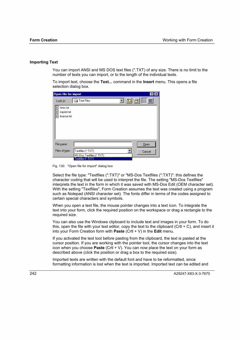
Form Creation Working with Form Creation
242 A29247-X83-X-3-7670
Importing Text
You can import ANSI and MS DOS text files (*.TXT) of any size. There is no limit to thenumber of texts you can import, or to the length of the individual texts.
To import text, choose the Text... command in the Insert menu. This opens a fileselection dialog box.
Fig. 130: "Open file for import" dialog box
Select the file type: "Textfiles (*:TXT)" or "MS-Dos Textfiles (*:TXT)": this defines thecharacter coding that will be used to interpret the file. The setting "MS-Dos Textfiles"interprets the text in the form in which it was saved with MS-Dos Edit (OEM character set).With the setting "Textfiles", Form Creation assumes the text was created using a programsuch as Notepad (ANSI character set). The fonts differ in terms of the codes assigned tocertain special characters and symbols.
When you open a text file, the mouse pointer changes into a text icon. To integrate thetext into your form, click the required position on the workspace or drag a rectangle to therequired size.
You can also use the Windows clipboard to include text and images in your form. To dothis, open the file with your text editor, copy the text to the clipboard (Crtl + C), and insert itinto your Form Creation form with Paste (Crtl + V) in the Edit menu.
If you activated the text tool before pasting from the clipboard, the text is pasted at thecursor position. If you are working with the pointer tool, the cursor changes into the texticon when you choose Paste (Crtl + V). You can now place the text on your form asdescribed above (click the position or drag a box to the required size).
Imported texts are written with the default font and have to be reformatted, sinceformatting information is lost when the text is imported. Imported text can be edited and
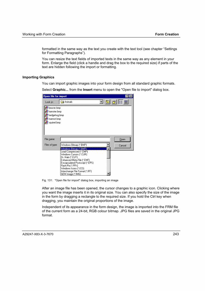
Working with Form Creation Form Creation
A29247-X83-X-3-7670 243
formatted in the same way as the text you create with the text tool (see chapter �Settingsfor Formatting Paragraphs�).
You can resize the text fields of imported texts in the same way as any element in yourform. Enlarge the field (click a handle and drag the box to the required size) if parts of thetext are hidden following the import or formatting.
Importing Graphics
You can import graphic images into your form design from all standard graphic formats.
Select Graphic... from the Insert menu to open the "Open file to import" dialog box.
Fig. 131: "Open file for import" dialog box, importing an image
After an image file has been opened, the cursor changes to a graphic icon. Clicking whereyou want the image inserts it in its original size. You can also specify the size of the imagein the form by dragging a rectangle to the required size. If you hold the Ctrl key whendragging, you maintain the original proportions of the image.
Independent of its appearance in the form design, the image is imported into the FRM fileof the current form as a 24-bit, RGB colour bitmap. JPG files are saved in the original JPGformat.

Form Creation Working with Form Creation
244 A29247-X83-X-3-7670
The image appears in 8-bit greyscale format in the Form Creation design window forrepresentation purposes and so that it can be generated as a printer resource from yourform.
If you selected a colour other than black as the default element colour in yourpreferences, an imported image is displayed in two colours. The portions of the originalimage which are in the selected element colour will appear in this colour, while areas notcontaining the element colour will display as greyscale. For the printer resource thismeans that the colour content of the element colour will be printed in CustomTone�.
See Chapter �Formatting Elements� for using colours and fill patterns with importedimages.
To accelerate screen refresh during the design process, you can suppress graphic displayin the design window. Uncheck aGraphic in the View menu. Instead of the image, aplaceholder now appears.
Importing Objects
To insert objects from other Windows applications into the form design, select Object...from the Insert menu. This opens the "Insert Object" dialog box.
Fig. 132: "Insert object" dialog box for inserting a file
In the "File" field enter the full path of the file you want to insert. Click the "Browse" buttonto open the selection dialog box where you can search for the file. The file you want toinsert as an object must be created by an OLE-capable Windows program.
When you confirm the file selection with "OK", the cursor becomes an OLE cursor. Movethe OLE cursor to the desired insertion point in the form and click the left mouse button toinsert the object in its original size. Or, with the mouse button pressed, drag the object

Working with Form Creation Form Creation
A29247-X83-X-3-7670 245
frame to the size you want the object. If you hold down the Ctrl key when dragging theobject frame, you maintain the original proportions of the object.
Independent of how they are displayed in the form design, graphic objects are importedinto the FRM file of the current form as 24-bit, RGB colour bitmaps. JPG files are saved inthe original JPG format. The image is converted to 8-bit greyscale format in the FormCreation design window for representation purposes and so that it can be generated as aprinter resource from your form.
If you selected a colour other than black as the default element colour in yourpreferences, an imported image is displayed in two colours. The portions of the originalimage which are in the selected element colour will appear in this colour, while areas notcontaining the element colour will display as greyscale. For the printer resource thismeans that the colour content of the element colour will be printed in CustomTone�.
Text objects are saved in the configured element colour. See Chapter �FormattingElements� for using colours and fill patterns with imported objects.
Double clicking the OLE object in the Form Creation design window opens the Windowsprogram associated with the object. You can then edit the object with the original programwithin Form Creation. When you exit the Windows program the object is saved again inForm Creation.
External References
References to external objects ensure that the SPDS print process produces a form with auniform appearance even if multiple form resources (page segments) are used. This isparticularly advisable when you want certain form sections in different forms to appear thesame.
When you create a reference to an external object, you insert a graphic object as aplaceholder in the form design; the placeholder should be the exact size needed by theexternal object when the form is printed. You can determine the precise size of theplaceholder if you use an Form Creation-developed overlay as an external object andinsert the EMF or WMF file generated by the overlay as a placeholder in the form design.
To insert a reference to an external object , select External References... from the Insertmenu to open the "External References" dialog box.
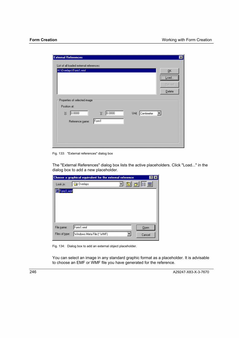
Form Creation Working with Form Creation
246 A29247-X83-X-3-7670
Fig. 133: "External references" dialog box
The "External References" dialog box lists the active placeholders. Click "Load..." in thedialog box to add a new placeholder.
Fig. 134: Dialog box to add an external object placeholder.
You can select an image in any standard graphic format as a placeholder. It is advisableto choose an EMF or WMF file you have generated for the reference.

Working with Form Creation Form Creation
A29247-X83-X-3-7670 247
Use "Open" to add the selected file to the list of active placeholders in the "ExternalReferences" dialog box.
"Properties of selected image" lets you assign a position in your form and enter areference name for the placeholder highlighted in the list.
Define the position of the placeholder by entering the X and Y co-ordinates of its topleft corner. You may use centimetres, inches or points for the units of measurement whenentering the co-ordinates. The co-ordinates 0:0 refer to the top left corner of the form; thisis the default entry until you change it.
For the reference name enter the name of the overlay (page segment) which is to beprinted for the placeholder. By default the file name of the placeholder is entered in thefield for the reference name.
Clicking "Delete" removes the highlighted placeholder from the list and removes thereference to the external object in the form design.
The image loaded as a placeholder displays in its original colours and size in the FormCreation window. To speed up screen refresh while working with Form Creation, you cansuppress the graphic display of the placeholder; a line-shaded rectangle displays insteadof the image.
To prevent placeholders from displaying in graphic form, uncheck aExternalReferences... in the View menu.
Editing Elements
Selecting Elements
You can select elements on the workspace with the pointer tool in order to format, move,resize or delete them.
(Ctrl+1)
Click an element to select it. A dotted selection frame appears around the element and ared selection dot appears in the top left corner.
If elements are fully hidden by other elements, the topmost element is selected. Ctrl + leftmouse button selects the next lower display level (refer also to the Changing elementlevels function).
You can select multiple elements by holding down the Shift key and clicking the elementsyou want to select. Each selected element displays a red dot in its top left corner. Aselection lasso appears around all selected elements.

Form Creation Working with Form Creation
248 A29247-X83-X-3-7670
When the pointer is active you can also hold down the left mouse button and drag arectangle over an element to select it; this selects all elements fully within the selectionframe.
Moving Elements
To move elements with the mouse:
• Select the element(s); a selection frame appears around the element(s).
• Move the cursor over the selected element(s); the cursor changes from a pointer to across.
• Press and hold the left mouse button and move the element(s) to the desired position.Form Creation aligns the element(s) to the grid.
Fig. 135: Selection frame and the cursor for moving
With the arrow keys you can move the selected element up, down, right and left in gridincrements.
For exact positioning, we suggest opening the "Position" window by selecting Positionfrom the View menu.
Fig. 136: "Position" window
In the "Top left" field you can enter the desired position of a selected element in the unit ofmeasurement appearing in the grid ruler.

Working with Form Creation Form Creation
A29247-X83-X-3-7670 249
If you change the entry of "Bottom right", the size of the element changes.
When you click "Set!" the element moves or is changed and the window closes.
You may also use units of measurement other than the default: cm for centimetres or "inches. After you click "Set!", the position is calculated for the selected unit ofmeasurement. If you do not enter a unit of measurement, the default unit is used.

Form Creation Working with Form Creation
250 A29247-X83-X-3-7670
Resizing Elements
To resize elements with the mouse:
• Select the element(s); a dotted selection frame appears around the element(s).
• Place the cursor over a handle; the cursor changes to a double-headed arrow andshows the directions available for resizing.
• Holding down the mouse button, drag the frame to the desired size.
Fig. 137: Selection frame, double-headed arrow for resizing
To maintain element proportions, press the Ctrl key when you drag the frame. Maintainingthe original proportions of the element is particularly important when working withimported bitmap images.
You can also change the size of a selected element in the "Position" window by changingthe entry in the "Bottom right" field (see Chapter �Moving Elements�). When you click"Set!", the element changes are saved and the window closes.
Copying Elements
To copy one or more elements to the clipboard:
• Select the element(s) with the pointer tool.
• Copy the element by selecting Copy in the Edit menu or by using Ctrl+C.
You can copy all elements in a form except placeholders for external objects.

Working with Form Creation Form Creation
A29247-X83-X-3-7670 251
Cutting Elements
To cut an element means to copy it into the clipboard and remove it from the form. To cutan element:
• Select the element(s) with the pointer tool.
• Cut the element(s) by selecting Cut in the Edit menu or by using Ctrl+X.
You can cut all elements in a form except placeholders for external objects.
Inserting Elements
By selecting Insert in the Edit menu or using Ctrl+V, you can insert an element saved tothe clipboard into a form.
An element copied (or cut and copied) into the clipboard retains all of its properties,including positioning.
If you insert an element from the clipboard from another Windows application, the cursorchanges to an image icon for images and a text icon for text.
Text formatting is lost when text is inserted from other Windows applications. Thestandard font is used for text inserted from other applications.
The clipboard content remains unchanged and can be inserted any number of times into aform.
Duplicating Elements
By selecting Duplicate from the Edit menu or using Ctrl+D, you can duplicate a selectedelement in the form.
Duplicates are vertically and horizontally offset in relation to the original when inserted.
You can change the vertical and horizontal offset distance by accessing DuplicateSettings... from the Options menu.
The Duplicate function corresponds to the Copy and Paste sequence, the difference beingthat the duplicated elements are not copied to the clipboard.

Form Creation Working with Form Creation
252 A29247-X83-X-3-7670
Replicating Elements
Replication is a function that produces multiple copies of selected elements and elementgroups.
Select Replicate from the Edit menu or press Ctrl+R to open the "Replicate" dialog boxwhere you can enter the number of copies and copy offset distances.
Fig. 138: "Replicate" dialog box
In the "Replicate Object" fields, enter the number of times the selected element is to becopied horizontally and vertically.
In the "Distance between objects" fields, enter the horizontal and vertical offset theelement is to be copied from the selected element. You may enter distances incentimetres, inches or points.
Fig. 139: An example of replication settings and result.

Working with Form Creation Form Creation
A29247-X83-X-3-7670 253
Aligning Elements
By selecting Align in the Arrange menu you can align multiple elements to horizontal andvertical lines.
Fig. 140: Alignment.
To align multiple elements, do the following:
⇒ With the pointer tool, select the elements to be aligned by holding down the leftmouse button and drawing a rectangle around them.
⇒ Open the Arrange menu.
⇒ Select Align (active only if two or more elements are selected) and then one of the sixalignment symbols:
− Vertical alignment left(aligns to the left edge of the selection rectangle)
− Vertical alignment centre(aligns to the vertical middle of the rectangle)
− Vertical alignment right(aligns to the right edge of the rectangle)

Form Creation Working with Form Creation
254 A29247-X83-X-3-7670
− Horizontal alignment top(aligns to the top edge of the rectangle)
− Horizontal alignment centre(aligns to the horizontal middle of the rectangle)
− Horizontal alignment bottom(aligns to the bottom edge of the rectangle)
You can align an object group horizontally as well as vertically. In this way circles ofdifferent sizes can be precisely aligned concentrically.
Arranging Elements
Elements in a form can cover each other partially or totally.
Each element is assigned to a display level. An element with a higher level is above andconceals a lower level element. When you generate overlays, macros, FOBs and EFOs,only the visible parts of elements are reproduced.
An exception is the printer fonts of text elements. These are generated independently ofthe data format as follows:
Data format How text is presented
SPDS Printer fonts always completely,independent of display level
PCL5e- (standard, optimised) Always completely,independent of display level
PCL5e- (bitmap) Text elements are suppressed
You can change the display level sequence (independent of the order elements wereinserted into the form) with the following functions in the Arrange menu:
• To Foreground
• To Background
• One up
• One down

Working with Form Creation Form Creation
A29247-X83-X-3-7670 255
Examples:
⇒ With the pointer tool, select an element that is partially hidden, and change the displaylevel using the One up command.
⇒ If an element is completely hidden, select the topmost element with the pointer. Ctrl +left mouse button selects the next lower display level; One up makes the displaylevel visible.
Deleting Elements
By selecting Delete from the Edit menu or using the DEL key, you can remove a selectedelement from the form.
By selecting Undelete from the Edit menu or using Alt + ← , you can reverse the lastdelete action.
Formatting Elements
To change the formatting of one or more elements, select the element(s) with the pointer.You can select a single element simply by clicking it; multiple elements are selected byholding down the left mouse key and drawing a selection frame around them.
If you select different kinds of elements at the same time (text, image, imported objects),formatting affects only those properties common to the selected elements.

Form Creation Working with Form Creation
256 A29247-X83-X-3-7670
The table below summarises which formatting applies to the elements.
Dis
tanc
e an
dro
tatio
n
Para
grap
h
Cha
ract
er
Elem
ent
colo
ur
Fill
patte
rn
Cor
ners
Line
art
Line
wid
th
Text field a a a a
Text paragraph a
Text character a
Line, open polyline a a a
Rectangle a a a a a
Ellipsis, circle a a a a
Closed polyline a a a a
Read lines a a a a
Imported image a a
OLE object a a
The various formatting options and settings are described in detail in "Defaults forFormatting Elements" (Chapter 6.1.4), "Entering Text" (Chapter 6.3.1.6) and "Editing Text"(Chapter 6.3.1.7).
Additional editing and formatting options for imported images and imported OLE objectsare in the pipeline.

Working with Form Creation Form Creation
A29247-X83-X-3-7670 257
Formatting Imported Images
To format an imported image, select Element Colour... from the Format menu to openthe "Format object" dialog containing the "Color" and "Bitmap type" tabs.
The settings you make here affect the presentation of the imported images on the FormCreation workspace and the way the printer resource is generated. The original imageremains unchanged in the background, allowing you to define new formatting for overlaysbased on the original image at any time.
The "Color" tab:
Fig. 141: Formatting an image, the "Color" tab
The "Color" tab allows you to set the raster type for the image object, assign an elementcolour to the entire image, and define dichromatic printing for printing systems which areCustomTone� capable.
Raster type:
Printing technology requires rasterizing in order to represent different colour intensities inimages. The more colour halftone dots there are in an area, the darker the area appears.In non-rasterized images there are only very dark and very light areas. The quality of a

Form Creation Working with Form Creation
258 A29247-X83-X-3-7670
printed image depends on raster density (i.e. how many colour dots can be in a certainarea) and how the colours of the original image are rasterized.
For printing imported images in your form you can choose "No raster" or "Standard"raster.
No raster: The areas of a picture are printed either very dark or very light based onthe colour content in the original image; gradations (grey shades forb&w printing) are not represented.
Standard raster: The image is rasterized; the density of the raster corresponds to theprinter resolution configured in the Form Creation resource generator.The colour pixels are evenly distributed in the raster grid; the number ofpossible gradations (grey shades for b&w printing) depends on rasterdensity.

Working with Form Creation Form Creation
A29247-X83-X-3-7670 259
Fig. 142: Raster samples: above, no raster; below, standard raster.
The raster samples here show magnifications of a transition from dark (lower left) to light(upper right).
In the magnified "No raster" sample the transition from black to white is clearly apparent.The area on the left is so dark that it is black, while the area on the right is completelywhite.
In the magnified standard raster sample you can see transition stripes from dark to light.These stripes may be seen when computer generated images are printed, disturbing theoverall image effect. These stripes are usually not apparent with scanned imagesbecause scanner noise blurs them.

Form Creation Working with Form Creation
260 A29247-X83-X-3-7670
Images in JPG format can be used in SPDS resources and printed in the original format.The "Standard" raster type is pre-set and cannot be changed.
Fig. 143: Direct printer output of JPG images in the SPDS resource.
Color:
You can assign an element colour to an imported graphic element just as you can with allother form elements.
If you assign black, the image is printed in black and white.
If you assign a colour other than black or white, the image will be printed completely inCustomTone� white on CustomTone� capable printing systems.
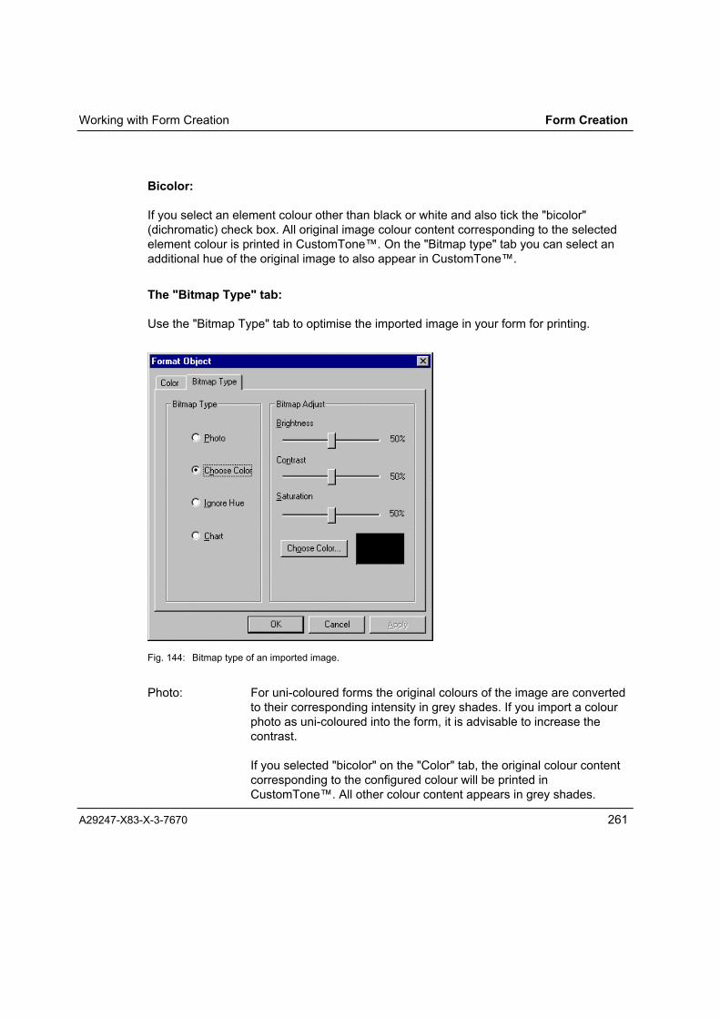
Working with Form Creation Form Creation
A29247-X83-X-3-7670 261
Bicolor:
If you select an element colour other than black or white and also tick the "bicolor"(dichromatic) check box. All original image colour content corresponding to the selectedelement colour is printed in CustomTone�. On the "Bitmap type" tab you can select anadditional hue of the original image to also appear in CustomTone�.
The "Bitmap Type" tab:
Use the "Bitmap Type" tab to optimise the imported image in your form for printing.
Fig. 144: Bitmap type of an imported image.
Photo: For uni-coloured forms the original colours of the image are convertedto their corresponding intensity in grey shades. If you import a colourphoto as uni-coloured into the form, it is advisable to increase thecontrast.
If you selected "bicolor" on the "Color" tab, the original colour contentcorresponding to the configured colour will be printed inCustomTone�. All other colour content appears in grey shades.

Form Creation Working with Form Creation
262 A29247-X83-X-3-7670
Choose Color: You can select this option only if you have selected an element colourother than black or white and have selected "bicolor" for printing theimage. If you tick "Choose Color", the "Choose Color" button appearsin the "Bitmap adjust" group box, as does a sample field with theselected colour. Clicking the "Choose Color" button opens the colourselection window from which to choose a primary colour or define acolour shade.The portion of the original image which is in the selected hue is printedin CustomTone�, as is the portion of the configured element colour.All other image colour content will be printed in black and white.
Ignore Hue: Ignoring hue is relevant only if you have configured an element colourother than black or white and have selected "bicolor" for printing theimage. All colours (other than black and white) of the original areprinted in CustomTone�.
Chart: By selecting "Chart" you can have various colours in an image (also ina one- or two-colour representation) appear differently.
With uni-colour printing, up to 16 of the original colours are clearly distinguishable; withtwo-colour printing (i.e. printing with CustomTone�) up to 100 coloursare distinguishable. Color gradations cannot be accurately reproduced.
Bitmap adjust: To optimise a picture for printing, you can incrementally increase ordecrease hue, contrast, and saturation. This allows you to increase thecontrast of colour photos represented in grey shades, for example.
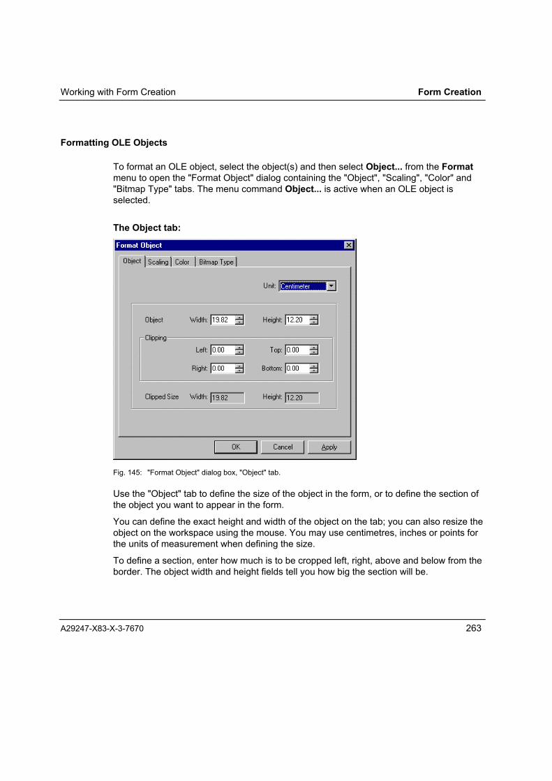
Working with Form Creation Form Creation
A29247-X83-X-3-7670 263
Formatting OLE Objects
To format an OLE object, select the object(s) and then select Object... from the Formatmenu to open the "Format Object" dialog containing the "Object", "Scaling", "Color" and"Bitmap Type" tabs. The menu command Object... is active when an OLE object isselected.
The Object tab:
Fig. 145: "Format Object" dialog box, "Object" tab.
Use the "Object" tab to define the size of the object in the form, or to define the section ofthe object you want to appear in the form.
You can define the exact height and width of the object on the tab; you can also resize theobject on the workspace using the mouse. You may use centimetres, inches or points forthe units of measurement when defining the size.
To define a section, enter how much is to be cropped left, right, above and below from theborder. The object width and height fields tell you how big the section will be.

Form Creation Working with Form Creation
264 A29247-X83-X-3-7670
The Scaling tab:
Fig. 146: "Format Object" dialog box, "Scaling" tab.
Use the "Scaling" tab to define the object size in the form by making it larger or smaller.
You can define the absolute height and width of the object in centimetres, inches orpoints; or you can increase or decrease the original size by entering a percentile of theoriginal size.
If you tick the "Keep aspect ratio" box, you can only set the absolute width or enter a widthpercent factor (the height adjusts automatically).
Clicking the "Natural size" button resets the object to its original size (X= 100%, Y=100%).
The "Color" and "Bitmap Type" tab:
You can use the "Color" and "Bitmap Type" tabs to set the same formatting parametersfor OLE objects as you can for imported images (see Chapter �Formatting ImportedImages�).

Working with Form Creation Form Creation
A29247-X83-X-3-7670 265
Proof Printing
By selecting Proof Print from the File menu or pressing Ctrl+P, you can print the currentform design on a PC printer.
Select the printer for the proof print using File/Choose Printer.../Proof Printing.
In proof printing, installed PC fonts most closely approximating printer fonts are usedinstead of printer fonts.
To what extent the proof looks the same as the form when it is printed on the Océ printingsystem depends on the extent to which the proof fonts match the printer fonts.
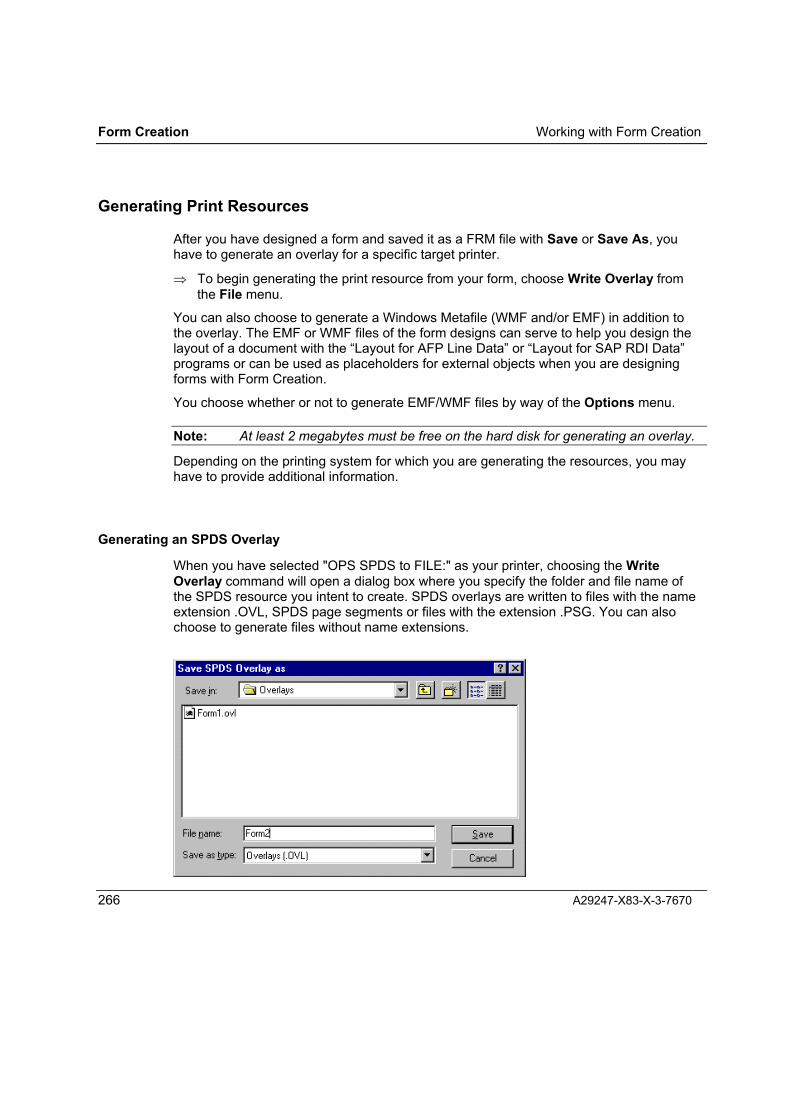
Form Creation Working with Form Creation
266 A29247-X83-X-3-7670
Generating Print Resources
After you have designed a form and saved it as a FRM file with Save or Save As, youhave to generate an overlay for a specific target printer.
⇒ To begin generating the print resource from your form, choose Write Overlay fromthe File menu.
You can also choose to generate a Windows Metafile (WMF and/or EMF) in addition tothe overlay. The EMF or WMF files of the form designs can serve to help you design thelayout of a document with the �Layout for AFP Line Data� or �Layout for SAP RDI Data�programs or can be used as placeholders for external objects when you are designingforms with Form Creation.
You choose whether or not to generate EMF/WMF files by way of the Options menu.
Note: At least 2 megabytes must be free on the hard disk for generating an overlay.
Depending on the printing system for which you are generating the resources, you mayhave to provide additional information.
Generating an SPDS Overlay
When you have selected "OPS SPDS to FILE:" as your printer, choosing the WriteOverlay command will open a dialog box where you specify the folder and file name ofthe SPDS resource you intent to create. SPDS overlays are written to files with the nameextension .OVL, SPDS page segments or files with the extension .PSG. You can alsochoose to generate files without name extensions.

Working with Form Creation Form Creation
A29247-X83-X-3-7670 267
Fig. 147: Saving an SPDS overlay
While the overlay is being output, a message box is displayed that counts the bands (tiles)as they are being produced. This keeps you informed on how the task is progressing, andalso tells you how many tiles (image blocks) are in the form.
Generating a PCL Macro
When you have selected "OPS PCL Macro to FILE:" as your printer, choosing the WriteOverlay command will open a dialog box where you specify the folder and file name ofthe PCL macro you intent to create. PCL macros are written to files with the nameextension .PCL or .MAC. The selected extension is stored as a default for subsequentmacro generations and as well to look up the macro IDs of already generated PCLmacros in the dialog �List all used macro IDs� (see page setup in chapter PCL MacroGenerator)
Fig. 148: Saving a PCL macro
If you have set "Optimized" or "Bitmap" as the optimisation option in the page setup dialogbox, the message "EMR-PCL Conversion is running" is displayed. If "Standard"optimisation is set, a box with the message "Writing the overlay" is displayed.
Generating a FOB Overlay
When you have selected "OPS FOB Macro to FILE:" as your printer, choosing the WriteOverlay command will open a dialog box where you specify the folder and file name ofthe FOB you intent to create. FOB overlays are written to files with the name extension.FOB.

Form Creation Working with Form Creation
268 A29247-X83-X-3-7670
When you click "Save" to close the dialog box in which you have specified the folder andfile name, the "Write Overlay (FOB)" dialog box opens for you to make further settings forgenerating your overlay.
Fig. 149: Write Overlay (FOB)
Settings in the "Write Overlay (FOB)" dialog box:
Start overlay on page: Specify the page on which the FOB is to be activated in theprinter (the FOB's starting copy number).
Copy overlay on Specify the number of copies (beginning with the starting copynumber) on which the FOB is to remain active in the printer).Example:Start overlay on page 1, Copy overlay on 1 pages.With these settings, the FOB will be printed on all the originals ofa document, but not on its copies.
You can enter any value between 1 and 254 in either field; note,however, that the sum of the values in the two fields may notexceed 255.You cannot set a copy number of 255 because this number isusually preset for header/trailer pages.If you want to use the FOB specifically for header/trailer pages,you can do this by setting the copy number 255 in the SIEPRTControl File (FOB).
Shift Overlay: Enables you to shift the entire FOB by up to 2 cm in thehorizontal and vertical directions during the generationprocedure.
Generating an LCDS Overlay
When you have selected "OPS LCDS to FILE:" as your printer, choosing the WriteOverlay command will open a dialog box where you specify the folder and file name ofthe LCDS file you intent to create. LCDS files have the extension .FRM.

Working with Form Creation Form Creation
A29247-X83-X-3-7670 269
Fig. 150: Destination folder and file name for LCDS resources
Note: The file with the load module is stored with the same name extension as theForm Creation form (.frm). Choose a different name for the LCDS resource, orenter the LCDS resources in a different folder. This will prevent the source filefrom being overwritten!
The file name may be up to six characters long, and may only contain the characters a toz, A to Z and 1 to 0. Invalid file names are rejected.
Fig. 151: Invalid file name
The LCDS Generator displays a message telling you that the generation process hasbegun. You can choose to cancel the process at this point.
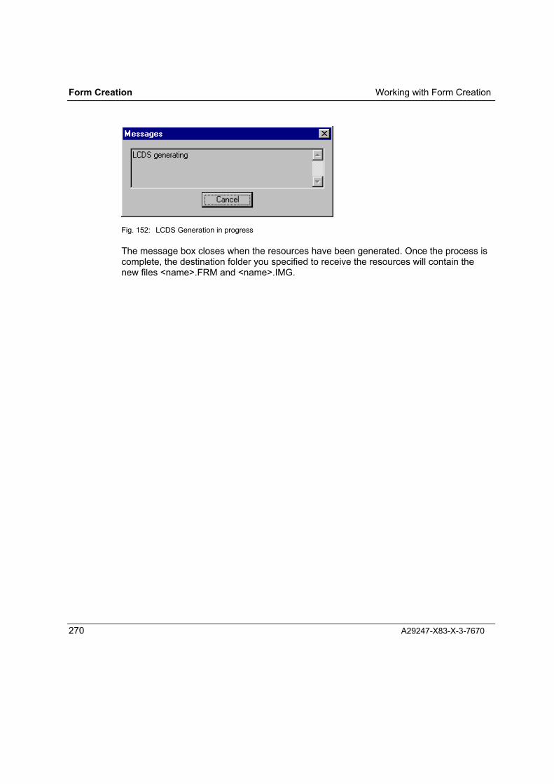
Form Creation Working with Form Creation
270 A29247-X83-X-3-7670
Fig. 152: LCDS Generation in progress
The message box closes when the resources have been generated. Once the process iscomplete, the destination folder you specified to receive the resources will contain thenew files <name>.FRM and <name>.IMG.

Working with Form Creation Form Creation
A29247-X83-X-3-7670 271
Transfer to the Printing System
Once generated, the print resources have to be transferred to the printing system. Thetransfer is via network or data medium. Various transfer paths can be used, depending onthe combination of resource format and destination printing system. The following tableshows which paths can be used in each case:
Resourceformat
Destination system Outputformat
Transfer Pre-print conversion of data ondestination system
SPS / BS2 TRANS1 FTP TransLib V2/ TransConSPS / MVS TRANS1 FTP TransLib V1 in MVSPSF / MVS Binary FTP Afpreblock in MVS
SPDS
PrismaPro(APA)
Binary FTP see Application Setup
PCL Printing system(e.g.PRISMAoffice)
Binary FTP
BS2 TRANS1 FTP Enter in OmsLib withOMSTRA (printing fromOmslib)
SIEPRT / MVS TRANS1 FTP TransLib
FOB
SIEPRT / VSE TRANS1 FTP TransLib + SIEFOBTPLCDS Xerox printing
systemBinary Diskette 5¼"
Xerox formatLow Densitycreated with"XERDISK"
Loaded via operator panel onXerox printing system
Transferring SPDS Resources
SPDS print resources are used on SPS printing systems controlled by BS2000 or MVS,on PSF printing systems controlled by MVS, and on PrismaPro (APA) systems.
For transfer to BS2000 the SPDS resources are output in TRANS1 format and sent overthe network using a file transfer program (FTP). Once they are on the BS2000 hostsystem, they are converted using TransLib V2 or TransCon.

Form Creation Working with Form Creation
272 A29247-X83-X-3-7670
For transfer to MVS for printing in SPS the SPDS resources are also output in TRANS1format and sent over the network using a file transfer program (FTP). Once they are onthe MVS host system, they are converted using TransLib V1.
For transfer to MVS for printing in PSF the SPDS resources are output in binary formatand sent over the network. Once they are on the MVS host system, the Afpreblockprogram is used to make them ready for printing.
For transfer to a PRISMAproduction (APA) printing system the SPDS resources areoutput in binary format and sent over the network. The names of the resource files mustbe lowercase characters and no file name extensions are permitted. Read chapter�Transfer to ODS Master�of Application Setup to learn more about the transfer of formstogether with a complete application
Transferring PCL Resources
PCL macros are transferred to the printing system (e.g. PRISMAoffice) over the networkas binary-format files via FTP.
Transferring FOB Resources
FOB resources are transferred over the network to the BS2000 system via FTP forprinting from OMSLIB. Once on the BS2000 system, they are entered in the OMSLIB.
For MVS-controlled printing in SIEPRT, the FOB resources are sent in TRANS1 format toMVS over the network using a file transfer program (FTP). Once they are on the MVS hostsystem, the resources are converted using TransLib V1.
For VSE-controlled printing in SIEPRT, the FOB resources are sent in TRANS1 format toVSE over the network using a file transfer program (FTP). Once they are on the MVS hostsystem, the resources are made ready for printing using TransLib and SIEFOBTP.
Transferring LCDS Resources
LCDS resources are used on XEROX printing system. The resources must be transferredto the printing system on a 5 ¼ " XEROX-format diskette (low density). Once on theXEROX printing system, the resources are loaded via the operator panel.
A utility called XerDisk is available from Océ for transferring the LCDS resources to aXEROX-format 5 ¼" diskette.

Form Import
A29247-X83-X-3-7670 273
FORMIMPORT

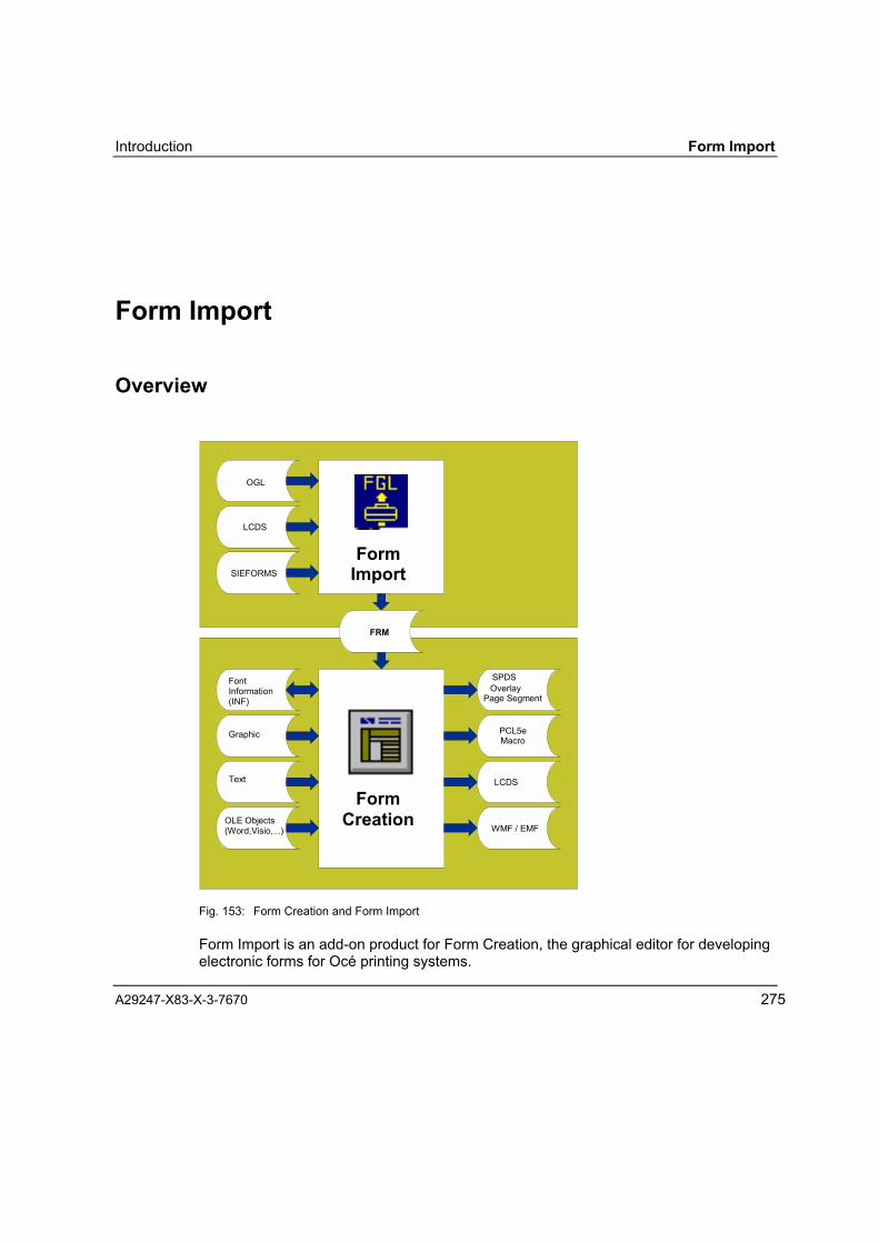
Introduction Form Import
A29247-X83-X-3-7670 275
Form Import
Overview
FormImport
FormCreation
FontInformation(INF)
Graphic
Text
OLE Objects(Word,Visio,...)
SPDSOverlay
Page Segment
PCL5eMacro
LCDS
WMF / EMF
FRM
LCDS
SIEFORMS
OGL
Fig. 153: Form Creation and Form Import
Form Import is an add-on product for Form Creation, the graphical editor for developingelectronic forms for Océ printing systems.

Form Import Introduction
276 A29247-X83-X-3-7670
You can use Form Import to convert electronic forms in OGL, LCDS or SIEFORMSformat to the proprietary FRM format of Form Creation and edit them with this program.
As a rule, Form Import is launched during an Form Creation session when you import asingle form in a non-native format for editing in Form Creation. However, Form Importcan also be used as a stand-alone program, and multiple forms can then be batch-processed.
ConverterYou can use Form Import to convert electronic forms from the following formats:
• OGL source texts in ASCII files (*.OGL)
• LCDS binary FRM files (*.FRM)
• SIEFORMS source texts in ASCII files (*.FSL)
to the internal FRM format of the program Form Creation.
The table below shows the formats to which a direct conversion of the various sourceformats is possible:
Output format
SPDS PCL LCDS
OGL !
LCDS ! ! !
Sour
cefo
rmat
SIEFORMS !
The forms to be converted must be on the same computer system. Form Importconverts the forms to FRM files and places these files in a folder of your choice.
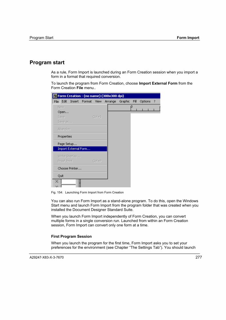
Program Start Form Import
A29247-X83-X-3-7670 277
Program startAs a rule, Form Import is launched during an Form Creation session when you import aform in a format that required conversion.
To launch the program from Form Creation, choose Import External Form from theForm Creation File menu..
Fig. 154: Launching Form Import from Form Creation
You can also run Form Import as a stand-alone program. To do this, open the WindowsStart menu and launch Form Import from the program folder that was created when youinstalled the Document Designer Standard Suite.
When you launch Form Import independently of Form Creation, you can convertmultiple forms in a single conversion run. Launched from within an Form Creationsession, Form Import can convert only one form at a time.
First Program SessionWhen you launch the program for the first time, Form Import asks you to set yourpreferences for the environment (see Chapter �The Settings Tab�). You should launch
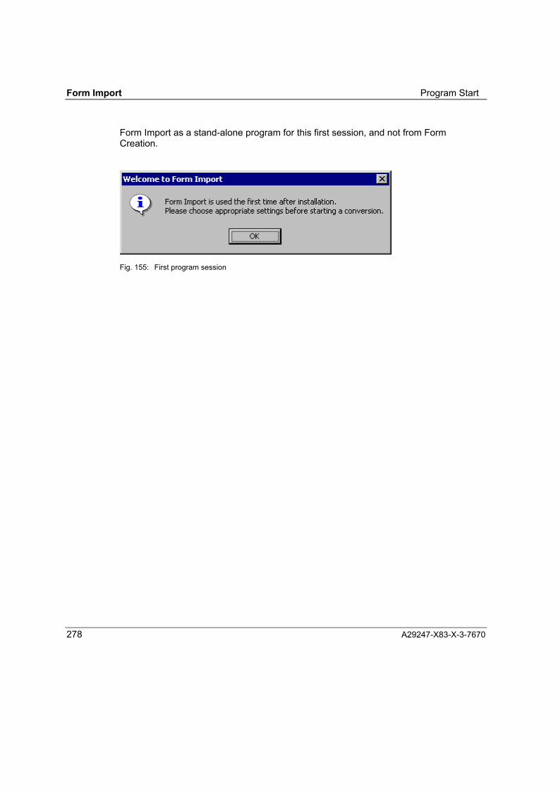
Form Import Program Start
278 A29247-X83-X-3-7670
Form Import as a stand-alone program for this first session, and not from FormCreation.
Fig. 155: First program session
User Interface Form Import
A29247-X83-X-3-7670 279
User InterfaceThe Form Import interface takes the form of a tab dialog box with four tabs:"Conversion", "Log View", "Settings" and "About". Click a tab to bring the relevant set ofoptions to the front of the dialog box.
Conversion Use this tab to specify which forms you want to convert (namesand locations) and where you want Form Import to place theconverted forms.
Log View Use this tab to view the results of a conversion in summarised ordetailed form.
Settings Use this tab to set preferences for your working environment andto specify the defaults to be used in conversions.
About This tab tells you which version of Form Import you are using andwhich program components you have installed.
Help opens the online help, which provides assistance on working with the program.
Clicking the Back to Form Creation button closes Form Import and returns to FormCreation.
If you launched Form Import as a stand-alone program, you exit the program by clickingClose.

Form Import User Interface
280 A29247-X83-X-3-7670
The Conversion Tab
Fig. 156: "Conversion" tab; Running Form Import in Form Creation
Use this tab to make the following settings:
• The source format of the form you want to convert (the "Input Type")
• The file name of the form to be converted
• The folder that is to receive the converted form
For an LCDS form, you can also specify whether the Form Creation form is to begenerated for printing with a portrait or a landscape orientation.

User Interface Form Import
A29247-X83-X-3-7670 281
When you launch Form Import as an independent program, you can convert severalforms � even forms of different formats � in a single conversion run. You will also seethe buttons "Add All" and "Remove All" on the Conversion tab (instead of "Add File"and "Remove File"). The "Back to Form Creation" button is replaced by the button"Close".
Fig. 157: "Conversion" tab; running Form Import as stand-alone program

Form Import User Interface
282 A29247-X83-X-3-7670
Specifying the Source FormatIn the "Input Type" box on the Conversion tab, check the format of the fonts you wantto convert.
You can choose between:
• OGL (*.ogl)
• LCDS (*.frm)
• SIEFORMS (FSL)
LCDS forms use the same file name extension as Form Creation forms. Be sure thatthe input file you specify does in fact contain a form in LCDS format.
Selecting an Input FileTo select an input file, proceed as follows:
⇒ Select an input folder. To do this, click the Browse button next to the InputDirectory field. This opens a dialog box for you to select the folder.
⇒ The Input Files list box displays all the files in the current folder that have a fileextension corresponding to the selected format. If you copy a form into the inputfolder after displaying the list, click the Refresh button to make it visible in the list.
⇒ Select an output folder (see below).
⇒ Select the desired files in the list of input files and click Add File to add them to thelist of files to convert. By clicking Add All you add all the files in the input files list tothe list of forms to convert.
You can enter any number of input files in the list of files to convert. The input files canhave different formats and different source folders, and you can also place theconverted form in a different folder in each case.
Selecting an Output FolderTo select an output folder, click the Browse button next to the Output Directory field.This opens a dialog box for you to choose a folder.

User Interface Form Import
A29247-X83-X-3-7670 283
Removing an Input File from the ListApart from the paper orientation for LCDS forms, you cannot change any of theparameters in the list of the forms to convert. To specify a different output folder for aconverted file, you have to remove the file entry, make your changes and then add thefile back to the list. Clicking the Remove button removes a selected entry from the list;clicking Remove All removes all the entries from the list.
To remove a specific file from the list, click the file name with the right mouse button.This opens a shortcut menu. Choose Delete from this menu to remove the file.
Changing the Orientation When Converting an LCDS FormForm Import automatically chooses the orientation � portrait or landscape on the paper� of a converted form to match either the instructions in the source format or thearrangement of the text elements on the form. However, for LCDS forms, you can setthe orientation manually if you wish.
With the right mouse button, click the name of the input file in the list of forms to beconverted. This opens a shortcut menu from which you choose Paper Orientation. Youcan choose between:
• Auto
• Portrait
• Landscape
The default is Auto.
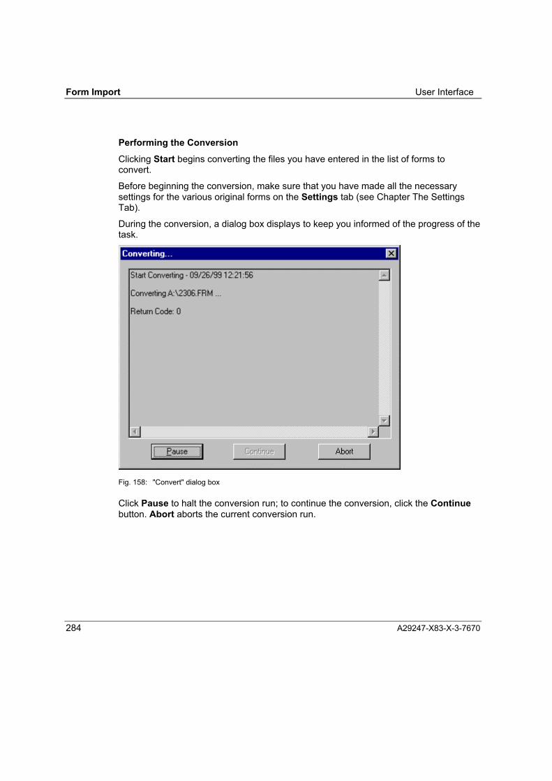
Form Import User Interface
284 A29247-X83-X-3-7670
Performing the ConversionClicking Start begins converting the files you have entered in the list of forms toconvert.
Before beginning the conversion, make sure that you have made all the necessarysettings for the various original forms on the Settings tab (see Chapter The SettingsTab).
During the conversion, a dialog box displays to keep you informed of the progress of thetask.
Fig. 158: "Convert" dialog box
Click Pause to halt the conversion run; to continue the conversion, click the Continuebutton. Abort aborts the current conversion run.

User Interface Form Import
A29247-X83-X-3-7670 285
The result of each file conversion is displayed with a return code:
Return Code Error Warnings Result
0 0 0 Converted completely, without errors
4 0 >0 Conversion incomplete (e.g. due to missingreference to resources), but FRM file created.
8 >0 Conversion aborted, no FRM file created.
16 Conversion aborted due to fundamentalproblem � e.g. missing or corrupt INI file.
When the entire conversion run is finished, a message box displays with the maximumreturn code:
Fig. 159: Conversion finished
You can choose whether to view the results log now. Click Yes to open the Log Viewtab.

Form Import User Interface
286 A29247-X83-X-3-7670
Mapping FontsSince Form Creation forms use different fonts than LCDS, OGL or SIEFORMS forms,Form Import will try to map each referenced original font to an Form Creation font onthe basis of the font mapping table. There is one font mapping table for each of thepossible direct format conversions (see table on page 276).
When Form Import encounters a font for which there is no entry in the font mappingtable, a dialog box is opened for you to add the requisite font to the table.
When you are converting an LCDS form, this dialog box appears only if you havechecked the Always prompt when no font substitute exists option on the Settingstab (see "Settings" Tab).
Fig. 160: Font mapping
In the "Substitute" section, enter the name of the LCDS, OGL or FSL font you want toreplace, plus the attributes of this font � its size, rotation, style and pitch.
⇒ The list beneath "Substitute by: Face Name / Style / Size" shows the fonts in thecurrent font library, which you select on the "Settings" tab. Select the font to beused in place of the LCDS, OGL or FSL font. When you select a font name, its filename, style and size are displayed in the dialog box. If several styles or sizes of a

User Interface Form Import
A29247-X83-X-3-7670 287
font are available under the same name, the styles and sizes are displayed for youto make your selection. You confirm your selection with OK.
You can change this font mapping later using the Edit Font Mapping Table buttonon the "Settings" tab. The button opens a dialog box where you can change the fontmapping settings (see Chapter "Settings" tab).
⇒ Click Cancel to stop Form Import working on the current input form. FormImport continues the conversion job with the next form.
⇒ Click Cancel All to stop Form Import working on the current conversion job.
The following special rules apply when you are converting an LCDS form:
• If you check the Use Font as Logo option, the LCDS font name will be added to theFont As Logos list in the LCDS Settings section on the Settings tab. This font willbe treated as a logo in all subsequent conversions.
• If you check the option Do not ask anymore, but use the same name, the originalfont name will be retained in the output form in this and all subsequent conversionsif the font has no substitute. The option deactivates the setting Always promptwhen no font substitute exists in the LCDS settings. It can only be reactivated bychecking the option again on the Settings tab.
⇒ Click Skip to stop Form Import from substituting the current LCDS font. The originalLCDS font name will be retained for the converted form.
Note: When converting an LCDS form, Form Import calculates bounding boxes fortext on the basis of the font characteristics of the original LCDS font.Therefore, the fonts referenced in the source file must be present on the PCduring conversion: You specify the paths of the fonts in the LCDS Fontsfield on the Settings tab.

Form Import User Interface
288 A29247-X83-X-3-7670
The Log View Tab
This tab displays the log of a conversion run.
The panel beneath Statistics presents the following information:
• How many files were processed in the conversion run;
• How many files were converted successfully;
• How many files were converted partially;
• How many files the system failed to convert;
• For how many files the conversion was aborted.
You can toggle between a detailed view and a summary by clicking theDetails/Summary button.
The Summary view indicates the results of the conversion, with one line per file. Thedetailed view displays the log for each individual form.
When you select an OGL or FSL source file for which a log file was created, the Editbutton is made available. Click this button to open the text editor for this file.
Use the Clear button to clear all the log entries (detailed and summary) from the LogView tab. Before deleting, Form Import asks you if you want to save all this informationto an ASCII file. Log files from OGL and SIEFORMS conversions are not deleted by thisaction.

User Interface Form Import
A29247-X83-X-3-7670 289
Summary Log
Fig. 161: "Log View" tab; summary
The columns in the Summary log provide the following information:
Input File Complete path of input file
Output File Complete path of output file
Log File Complete path of log file, or "Not Applicable" when no log wascreated.
Time Date and time of the conversion run
Type Type of form in the input file
Status Result of the conversion runSuccessful: converted successfully, no warningsIncomplete: converted partially, warningsFailed: Conversion failed, input format errorAbend: Conversion aborted, fundamental error
Detail Log

Form Import User Interface
290 A29247-X83-X-3-7670
Fig. 162: "Log View" tab; Details
The messages that are shown in the detail log are explained in chapter Working withForm Import.

User Interface Form Import
A29247-X83-X-3-7670 291
The Settings Tab
Use the functions on this tab to set the parameters for converting the original forms.
The tab comprises three sections:
• Section for making settings for the input file
• Section for making settings for the output file
• Settings for the Form Import program
You have to make different settings for each of the input formats.
Fig. 163: "Settings" tab (LCDS)

Form Import User Interface
292 A29247-X83-X-3-7670
Settings for Converting (OGL, LCDS, SIEFORMS)
Depending on the input format different settings are applicable.
OGL Settings)
Image Path Complete path of graphic file (*.pcx) to replace page segments
Cat File Complete path of CAT file (*.cat) for converting text. A selectionof CAT files for usual cases can be found in the Form Importinstallaion directory.
LCDS Settings)
Code Mapping LCDS forms use national code mappings. To convert the codescorrectly to ASCII, Form Import must know which national codingwas used in the original form.
LCDS Font Form Import will try to substitute a referenced LCDS font with onethat the output printer driver can support. However, in thecalculation of bounding boxes for text, it still uses the fontattributes of the original LCDS fonts. Hence, Form Import mustbe able to access the referenced LCDS fonts. Enter the foldercontaining the referenced fonts here.
LCDS Logo Logos in LCDS forms are converted to Form Creation bitmapelements, and not externally referenced. Form Import must beable to access the originals of these logos. Enter the foldercontaining the logos here.
LCDS Image Images in LCDS forms are converted to Form Creation bitmapelements, and not externally referenced. Form Import must beable to access the originals of these images. Enter the foldercontaining the images here.
Font as Logo Since LCDS fonts can be used as logos as well, there is no wayto distinguish whether a font referenced in an LCDS form isactually meant to be used as a font or as a logo. In the lattercase, the bitmap pattern must be included in the source (input)form. Therefore, you need to specify which LCDS fonts are to beused as logos.
Always promptwhen no fontsubstitute exists
Since LCDS and Form Creation forms use different fonts, FormImport will try to map each referenced LCDS font to a FormCreation font. Form Import searches the font mapping file for thecurrent Form Creation output format (for example, the filespds.fmt). If Form Import is unable to locate an entry for the font,it displays a dialog box to prompt you to supply a font substitute.Once you have specified a substitute, Form Import adds it as a

User Interface Form Import
A29247-X83-X-3-7670 293
new entry to the font mapping file. If you do not check theAlways prompt when no font substitute exists option, FormImport will convert "silently", retaining the name of the originalLCDS font. When Form Creation loads the converted form, youwill be prompted to name the substitute.
SIEFORMS Settings
Image Path Complete path of graphic files (*.gds)
Text Path Complete path of text files (*.txt)
Line StylesComplete path of line style definition file (*.frl). A selection of FRLfiles for usual cases can be found in the Form Import installationdirectory.
Fill Patterns:Complete path of fill pattern file (*.frp). A selection of FRP files forusual cases can be found in the Form Import installationdirectory.
Cat FileComplete path of CAT file (Translation table) (*.cat). A selectionof CAT files for usual cases can be found in the Form Importinstallation directory.

Form Import User Interface
294 A29247-X83-X-3-7670
Edit Font Mapping Table:
Click this button to open the Font Mapping Table dialog box. Use this dialog box toadd, modify, remove, import and export font mappings.
Fig. 164: Font mapping table (OGL conversion)
The display of the font mapping table dialog depends on the selected input and outputformat. For each combination of input and output formats a separate font mappingtable is used.

User Interface Form Import
A29247-X83-X-3-7670 295
Add:
When you click the Add button, Form Import opens the "Font Substitution: AddOGL/LCDS/FSL Name" dialog box for you to add a new entry to the current fontmapping table.
Fig. 165: "Font Substitution: Add OGL Name" dialog box
In the "Font Name" field in the "Substitute" section, enter the source-text font that youwant to substitute; beneath "Substitute by: Face Name / Style / Size", select asubstitute font from the list of fonts in the current font library. The new entry is assignedthe resolution that you have set on the "Settings" tab.
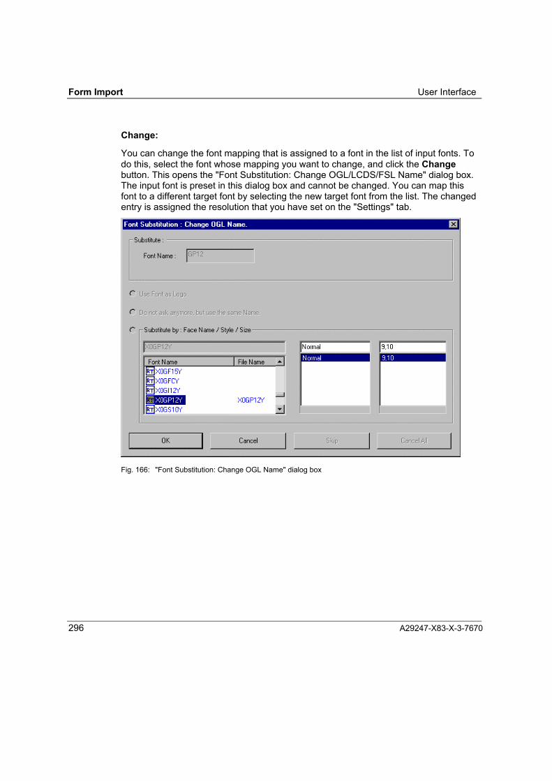
Form Import User Interface
296 A29247-X83-X-3-7670
Change:
You can change the font mapping that is assigned to a font in the list of input fonts. Todo this, select the font whose mapping you want to change, and click the Changebutton. This opens the "Font Substitution: Change OGL/LCDS/FSL Name" dialog box.The input font is preset in this dialog box and cannot be changed. You can map thisfont to a different target font by selecting the new target font from the list. The changedentry is assigned the resolution that you have set on the "Settings" tab.
Fig. 166: "Font Substitution: Change OGL Name" dialog box

User Interface Form Import
A29247-X83-X-3-7670 297
Remove and Remove All:
Remove removes the selected font mapping entries. Remove All removes all entriesfrom the current font mapping table.
Import:
Font mapping lists are stored in FMT files (*.fmt). You can import external FMT filesfrom other folders for your conversion tasks. To do this, click the Import button. In thedialog box that displays, select the file from which you want to import the mapping.
Export and Export All:
You might wish to make your font mappings available to other Form Import users. Youcan do this by exporting selected entries or the entire current table to an FMT file. Toexport part of the table, select the entries you want to export and click the Exportbutton. To export the entire table, click Export All. In both cases, a dialog box opens inwhich you specify the file to which you want to export.
Save:
Save saves your changes to the current font mapping and closes the Add FontMapping dialog box.
Close:
This button closes the dialog box without saving the current table. If you attempt toclose without saving your settings, you are asked if you want to save your changes. Ifyou reply "no", all the settings you have made since you last saved are discarded.

Form Import User Interface
298 A29247-X83-X-3-7670
Edit Fill Pattern
This option is only available with the conversion of LCDS forms. Click on �Edit FillPattern� opens the dialog window for the design of fill patterns.
Fig. 167: Edit pattern
You can define three shadings for fill patterns and edit these patterns using the patterneditor. By selecting a suitable pattern, you can adjust shadings for the form beingconverted to the shadings of the original.Form Creation Settings

User Interface Form Import
A29247-X83-X-3-7670 299
Form Creation Settings
Output Format:
You can choose the output format for which you intend to generate the form in FormCreation.
OGL : You can choose SPDS.
LCDS : Choose between SPDS, PCL or LCDS.
SIEFORMS: You can choose SPDS.
Resolution (dpi):
Select the resolution of the printer on which you intend to print the converted form: 240,300 or 600 dpi
This option is not available with conversions of LCDS forms since this conversionalways implies a resolution of 300 dpi..
Note: If there are images (GDS) in your form, we recommend converting to theoriginal resolution.
Font Library:
Set the path of the font library for device fonts here. This option is only available foroutput format SPDS. For output formats PCL and LCDS only the windows installedsystem fonts are used.
< Form Creation Default> This setting is possible only under Windows NT and whenForm Creation is installed. When you choose this setting, thecurrent Form Creation font library is selected automatically on thebasis of the resolution which is active. This is the recommendedsetting.
<Path> If you are working under Windows 95 or do not have Form Creationinstalled, you have to select the path to an Form Creation fontlibrary (FONTS.SUM). The fonts in this library should match theresolution you have selected.
Form Import Settings
Language
Use this option to set the language of the Form Import interface. You can choose eitherGerman or English.


Working with Form Import Form Import
A29247-X83-X-1-7670 301
Working with Form Import
Converting Forms
To convert LCDS-, OGL or SIEFORMS forms into forms editable in Form Creation youproceed as follows:
After you have launched Form Import, the Form Import window opens. This is a tabdialog box with four tabs: "Conversion", "Log View", "Settings" and "About". Click a tabto bring the relevant set of options to the front of the dialog box.
⇒ On the Conversion tab, select the source format (input type) of the forms you wantto convert. Specify the source (input) folder containing the forms to be converted,and the destination folder in which you want to place the converted forms. In theconversion list, enter the names of the forms you want to convert.
⇒ Bring the Settings tab to the front of the dialog box. On this tab, select the outputformat you want to generate. Specify the folders in which Form Import will find theresources and translation tables it needs. Also indicate which fonts are tosubstitute the original fonts in the forms, and which fill patterns are to be used.
⇒ To start the conversion, click the Start button on the Conversion tab.
⇒ Check the results of the conversion on the Log View tab.

Form Import Converting OGL Forms
302 A29247-X83-X-3-7670
Converting OGL Forms
General Notes
• OGL forms can be converted to the output format SPDS.
• The OGL sources must be on the PC in the form of ASCII files. As a rule, the OGLsource file is transferred from a host system using a File Transfer Program (FTP).You must select the format "text" (not "binary") in the program.
• The converter processes all OGL commands that can have equivalents in the FormCreation program.
• The OGL fonts are assigned the corresponding Form Creation fonts by way of amapping table.
• The page segments must be on the PC as PCX files.
• OGL sources must be syntactically correct. JCL statements within OGL sources arenot allowed, and nor are line counts in columns 72 to 80 of the OGL source. Deletethese before the conversion.
• When it converts a form, the OGL converter creates a log file in the same folder asthe destination file. The log provides details about the conversion.
• If the converter encounters a syntax error, it aborts processing without creating anFRM file and writes an error message to this effect to the log file.
• You will find the converted form in a file called <name>.frm in the output folderwhich you selected on the "Conversion" tab in Form Import.

Converting OGL Forms Form Import
A29247-X83-X-3-7670 303
Transfer and Character Conversion
As a rule, the OGL source file is transferred from the host to the PC using a FileTransfer Program (FTP). You must select the format "text" (not "binary") in theprogram. This ensures that the FTP automatically converts the file from host coding(EBCDIC) to PC coding (ASCII). The conversion is based on a code table in the FTP.Many programs allow you to select and edit these tables.
OGL commands are converted without any difficulty, but there is a possibility ofmisinterpretation of special characters in character strings (text type CHAR inSETTEXT, WITHTEXT commands). The FTP conversion table may be unable toconvert these characters correctly.
If, following the conversion, characters which you could enter via the keyboard in FormCreation are presented in the form as non-printable characters, please verify that allthe character strings in the OGL source are readable; also check which coding is used,and then specify a suitable CAT file for the conversion. Proceed as follows:
⇒ Open the source file with a DOS editor or WordPad (file type: "Text Documents �MS-DOS Format"). If the characters are readable, the OGL source uses MS-DOScoding (ASCII).Select the CAT file ASCIANSI.CAT on the "Settings" tab in Form Import. Thenconvert the file again.
⇒ Open the file with Notepad or WordPad (file type: "Text Documents"). If thecharacters are readable here, the OGL source uses Windows coding (ANSI).Select the CAT file SET00000.CAT on the "Settings" tab in Form Import. Thenconvert the file again.
⇒ If the special characters are not readable in either format, this means the FTPprogram has generated an invalid character code. Change the charactersmanually, edit the FTP conversion table, or create your own custom CAT file.
⇒ If the strings in the OGL source have hex character coding, Form Import maps thecode to Windows ANSI using the internal mapping of the selected destination font(selected on the basis of the font mapping table). In the event of problems,substitute with a font that contains the desired character.

Form Import Converting OGL Forms
304 A29247-X83-X-3-7670
Notes on Converting OGL Forms
Ruler division The ruler is in centimetres with 0.1 cm divisions.
Grid The grid is in centimetres with 0.1 cm divisions.
Placement No check is performed for out-of-bounds placement.
Graphic elements placed beyond the boundaries of the form aredisplayed by Form Creation in the grey zone outside the form.
Correct the size of the page manually if necessary.
Fonts All fonts in the forms being converted are substituted by the fonts inthe current Form Creation font library, in accordance with thespecifications in the font mapping table.
If a font is not entered in the font mapping table, the converter issuesa warning message during the conversion and prompts the user toenter a substitute.
Segments The page segments addressed in the OGL sources must be on thePC in the form of bitmap files (PCX).
The name of the PCX file must be the member ID (see OGL manual).Example: OGL source:
SEGMENT DUMMA DSTR DDNAME SEGDD;
The converter looks for the PCX file in the folder specified in the OGLsettings.
Bitmap files must be created as black/white bitmaps.
Language The OGL2FGL converter supports only English OGL commands.

Converting OGL Forms Form Import
A29247-X83-X-3-7670 305
Shadings OGL works with 10 fixed shadings. One custom shading value canbe defined by specifying a percentage value.
Form Creation supports eight defined shadings.
For custom shadings, you have to define your own shadings prior toconverting the file.
Form Creation supports only the OGL standard shadings.
The OGL screen shadings are not supported; however, you candefine them yourself and save them as a shading file under FormCreation.
Shading assignments:
OGL shadings Form Creation shadings
XLIGHT Shading Number 1
LIGHT Shading Number 2
MEDIUM (default) Shading Number 4DARK Shading Number 6
XDARK Shading Number 7
CONTROL Not supported; OGL-specific.

Form Import Converting OGL Forms
306 A29247-X83-X-3-7670
Conversion of OGL Commands
All OGL statements with equivalent functions in Form Creation are converted. This alsoapplies to OGL commands that can be represented by graphical elements in FormCreation. If an OGL command contains special subcommands that cannot berepresented by Form Creation, these subcommands are ignored, and a warning isentered in the log file.
OGL Commands Remarks
DEFINE Multiple occurrences of groups permitted, with n graphics elements.
Patterns are not supported.
OGL provides a facility for outputting defined patterns in varioustypes of shading.
This function is seldom required by end users, since the patternitself has to be coded in bit form (complex procedure, appearancenot satisfactory)
DRAWBOX Diagonals are not supported by Form Creation.
The text function is restricted; see Settext. In addition, theBALANCE text formatting function is not supported by FormCreation; BALANCE is treated in the same way as JUSTIFY.
DRAWCIRCLE Semi-circles and quarter-circles, axes and diagonals are notsupported by Form Creation.
The text function is restricted; see Settext. In addition, theBALANCE text formatting function is not supported by FormCreation; BALANCE is treated in the same way as JUSTIFY.
DRAWMASK Not supported; help function for designing an OGL form.
DRAWPATH Mapped to an Form Creation polygon element.
The subcommand CONNECTION and the second option in thesubcommand PATHEND are not supported.
DRAWRULE See OGL manual for function.
ENDDEF See OGL manual for function.
FONT Font statements for MVS, VM and VSE are processed.
ORIENT Ignored; overlays are always created with 0 degree rotation.
A rotation would make the overlay most difficult to process in FormCreation.

Converting OGL Forms Form Import
A29247-X83-X-3-7670 307
OGL Commands Remarks
OVERLAY The overlay name and offset are ignored.
If you require an offset, you must specify it when writing the overlay.
PLACE 1. Segments and groups.
2. Place Pattern is not supported. See Define.
POSITION See OGL manual for function.
SETTEXT Double-byte fonts are not supported.
SOSI1 and SOSI2 are not supported.
The characters (text type CHAR) are converted by way of atranslation table (CAT). Please refer to the general remarks inAppendix B1.1. If text type �HEX� is specified, it is possible that theconverted characters will not be presented correctly in FormCreation. This is because there are no equivalent ANSI codes forthese characters (e.g. custom-designed symbols).
The converter does not support symbolic data sets or symbolicfiles.
Form Creation does not support COLUMN and TATE textformatting.
SETUNITS See OGL manual for function.

Form Import Converting OGL Forms
308 A29247-X83-X-3-7670
OGL Converter Error Messages
If the OGL converter encounters errors when converting an OGL form, it enters them inthe log file. The table below lists the error messages that the converter can enter in thelog.
Error no. TextDGF01 Cannot memory for allocate group file. Conversion terminated.
FE010 Unable to find source file or path.
FE011 Unable to find CAT file or path.
FE012 Unable to find log file or path.
FE013,FE015,FE017
Unable to find temp file or path.
FE014 Unable to find source file or path.
FE016 Unable to find group file or path.
FE020 Unable to delete group file.
FE040 Unable to find bitmap file or path.
FE041 Bitmap file corrupt.
FE042,FE043
Unable to open bitmap file.
FNT01 No font assigned to this font name. Conversion terminated.
FST03 Unable to find valid font substitution table. Conversion terminated.
ME001..:ME009
Not enough memory.
COM01 Error in comment (semicolon). Incorrect comment. Conversionterminated.

Converting OGL Forms Form Import
A29247-X83-X-3-7670 309
OGL Converter Warnings
If the OGL converter encounters problems when converting an OGL form, it entersthem in the log file as warning messages. The table below lists the warning messagesthat the converter can enter in the log.
Warning no: Text
WBDia01 Box DIAGONAL command is not supported by Form Creation.
WCas002 Circle AXIS HORIZONTAL command is not supported by Form Creation.
WCas003 Circle AXIS VERTICAL command is not supported by Form Creation.
WCas004 Circle AXIS BOTH command is not supported by Form Creation.
WCDia01 Circle DIAGONAL command is not supported by Form Creation.
WChb001 Circle HALF BOTTOM command is not supported by Form Creation.
WChl001 Circle HALF LEFT command is not supported by Form Creation.
WChr001 Circle HALF RIGHT command is not supported by Form Creation.
WCht001 Circle HALF TOP command is not supported by Form Creation.
WCqb001 Circle QUARTER BOTTOMLEFT command is not supported by FormCreation.
WCqb002 Circle QUARTER BOTTOMRIGHT command is not supported by FormCreation.
WCql001 Circle QUARTER TOPLEFT command is not supported by Form Creation.
WCqt002 Circle QUARTER TOPRIGHT command is not supported by FormCreation.
WDPc001 The command CONNECTION and belonging commands are notsupported by Form Creation.
WDPpe001 A second option in command PATHEND is not supported by FormCreation.
WPat001 Pattern command is not supported.
WShd001 Shading in percent command is not supported by Form Creation.
WSos001 SOSI1 command is not supported by Form Creation.
WSos002 SOSI2 command is not supported by Form Creation.
WTba001 BALANCE text formatting command is not supported by Form Creation.
WTco001 COLUMN text formatting command is not supported by Form Creation.
WTta001 TATE text formatting command is not supported by Form Creation.

Form Import Converting LCDS Forms
310 A29247-X83-X-3-7670
Converting LCDS Forms
General Notes
• LCDS forms can be converted to the output formats SPDS, PCL and LCDS.
• To convert an LCDS form, all the required resources must be available on the PC(i.e. forms, images, logos and fonts).
• Form Import sets the paper orientation (portrait or landscape) to match thearrangement of the text elements on the form. However, you can set the orientationmanually if you wish.
• LCDS forms use national code mappings. To convert these codes to ASCII, youhave to specify the country for which the characters in the LCDS form were coded.
Notes on the Conversion
LCDS forms can include five different types of objects:
• Texts
• Lines
• Shades
• Images
• Logos
Each is converted to a particular Form Creation element. At present, colour elements inLCDS sources are mapped to black.
Texts:When converting text objects from LCDS format to Form Creation format, Form Importcalculates the text bounding box by retrieving the font information from the LCDS fontfiles.
Since LCDS and Form Creation forms use different fonts, Form Import will try to map areferenced LCDS font to an Form Creation font on the basis of the font mapping table.There is one font substitution table for each Form Creation source format (SPDS, PCLand LCDS).

Converting LCDS Forms Form Import
A29247-X83-X-3-7670 311
If Form Import is unable to locate an entry for the font, it displays a dialog box toprompt you to supply a font substitute. Once you have specified a substitute, FormImport adds an entry to the font mapping file. If you do not check the Always promptwhen no font substitute exists option, Form Import will convert "silently", retainingthe name of the original LCDS font. When Form Creation loads the converted form, youwill be prompted to name the substitute.
Lines and Shades:The Line and Shade patterns of an LCDS form are defined in the file FORMS$.FNT. InForm Import, you can use Edit Fill Patterns in LCDS Settings to define three levels ofshadings. These are saved to the configuration file XRXCFG.INI.In an LCDS form, an entire line or shade might be divided into more than one object.This is because lines and shades are represented by characters whose patterns arefixed-size lines or shades. When converting, Form Import combines these charactersto create a single element.
Images:Images in LCDS forms are converted to Form Creation bitmap elements. Form Importuses the Adaptive Format compression method.
Logos:It is assumed that each LCDS logo file contains only one logo object. The object maybe represented by several characters. When converting, Form Import combines thematrices of these characters to create a single Form Creation bitmap element.

Form Import Converting LCDS Forms
312 A29247-X83-X-3-7670
How the LCDS objects are converted:
LCDS objects Form Creation Element
Text Box with
LineWidth = 0FillIndex = TransparentAdditional text
Line LineLineWidth > 0LineType = Line pattern + CUT_CAP (defined in XFXCFG.INI)
Shade Box withLineWidth = 0FillIndex = Fill pattern (defined in XFXCFG.INI)No additional text
Image Bitmap image
Logo Bitmap image

Converting LCDS Forms Form Import
A29247-X83-X-3-7670 313
LCDS Converter Messages
The detailed view on the Log View tab lists messages that tell you how an LCDSconversion has proceeded. There are progress messages, status messages, warningsand error messages.
The progress and status messages notify you that a specific conversion action istaking (or has taken) place, for example: "Reading LCDS Objects...", "Writing FGLelements..."). They also notify you of the results of a conversion, for example: "Numberof FGL elements: 40"). The LCDS converter's progress and status messages are allself-explanatory.
Warnings alert you to problems which can be ignored or resolved during theconversion but which will impact on the results. For example, if resources (a font, forexample) are missing from the specified folder, the element is simply ignored duringthe conversion. The LCDS converter's warnings are all self-explanatory.
Error messages notify you of problems that prevent the conversion of the LCDS form.The LCDS converter's error messages are self-explanatory, and it is generally clearfrom the content of the message what action you have to take to correct the problem.
For the following system-related errors, we recommend the action specified in themessage:
Error 101: No config file. The converter was unable to find the configuration fileXFXCFG.INI in the Windows folder. Install Form Importagain.
Error 102: Error in INI file The configuration file XFXCFG.INI is corrupt. Theconversion problems depend on how badly the file iscorrupted. You might be given extra information statingwhich section/entry of the file is corrupted.If you cannot repair the file, install Form Import again.
Error 502 Cannot open file Form Import is unable to open an input file or is unableto create an output file. The output folder might be write-protected, or a write-protected file of the same namemight already exist.
Error 610Illegal LCDS Form Format
The input form is not a valid LCDS form. A similarmessage is issued for invalid LCDS resources (fontsetc.). Remember that LCDS forms and Form Creationforms have the same file name extension (FRM).

Form Import Converting SIEFORMS Forms
314 A29247-X83-X-3-7670
Converting SIEFORMS Forms
General Notes
• SIEFORMS forms can be converted to the output format SPDS.
• The SIEFORMS sources must be on the PC in the form of ASCII files. Beforeconverting, select the CAT file ASCIANSI.CAT on the "Settings" tab in FormImport.
• The converter processes all SIEFORMS commands that can be reproduced by theForm Creation program.
• Fonts in the SIEFORMS forms are substituted by fonts available in the current FormCreation font library, in accordance with the specifications in the mapping table.
• Embedded graphics must be on the PC in *.gds files; embedded texts must be onthe PC in *.txt files.
• The conversion of lines and fill patterns is based on printer-specific configurationfiles.
• You will find the converted form in a file called <name>.frm in the source folderwhich you set on the "Conversion" tab in Form Import.
• In processing a SIEFORMS source, the SIEFORMS converter creates a log file(<name>.log) in the same folder as the source. This file contains a copy of theoriginal SIEFORMS form, plus warnings and error messages relating to theconversion (conversion log).
• The converter requires syntactically correct SIEFORMS forms. If the converter doesencounter a syntax error, processing aborts with an error message and no FRM fileis created.

Converting SIEFORMS Forms Form Import
A29247-X83-X-3-7670 315
SIEFORMS Configuration and Definition Files
Form Import ships with configuration and definition files for a number of destinationprinters. These files control how lines and fill patterns are converted:
FOBSha.frp File of fill pattern definitions corresponding to FOB patterns in theSIEFORMS base system.
AFPSha.frp File of fill pattern definitions corresponding to IBM AFPDS patternsin the SIEFORMS base system.
FGLDEFAU.frp Definition file with Form Creation default fill patterns.
LineDef.frl Definition file with Form Creation default line styles.
These definition files are located in the installation folder. You can edit them usingForm Creation program functions.
S2FCFG.INI
You can edit the line and fill pattern assignments in the configuration file S2FCFG.INIto suit your requirements. However, be sure to make a backup copy of the originals!The configuration file is in the Windows folder. You can edit it using a standard textediting program.

Form Import Converting SIEFORMS Forms
316 A29247-X83-X-3-7670
Section for assignment of line styles and predefined line widths:
[LineStyles]
Hairline=<Line width in DOTS>
Normal=<Line width in DOTS>
Wide=<Line width in DOTS>
Solid=<Index in FRL file>
Dotted=<Index in FRL file>
Broken=<Index in FRL file>
Section for assignment of fill patterns:
[FillPattern]
Light=<Index in FRP file>
Medium=<Index in FRP file>
Heavy=<Index in FRP file>
Pattern000=<Index in FRP file>
.
.
.
Pattern200=<Index in FRP file>

Converting SIEFORMS Forms Form Import
A29247-X83-X-3-7670 317
Index in FRL file: Permitted values: 0..8, where0 =solid line1..8 = true reference to FRL file
Index in FRP file: Permitted values: 0..9, where0 = white1..8 = true reference to FRP file9 = filled in
FRL file Each FRL file (e.g. LineDef.frl) contains the Form Creationbitmap information for eight line styles; you can load the file intoForm Creation, modify the styles and save the file under adifferent name (menu command: Edit Line Types).
FRP file Each FRP file contains the Form Creation bitmap information foreight fill patterns; you can load the file into Form Creation,modify the patterns and save the file under a different name(menu command: Edit Pattern).

Form Import Converting SIEFORMS Forms
318 A29247-X83-X-3-7670
Conversion of SIEFORMS Commands
All SIEFORMS statements with equivalent functions in Form Creation are converted.This also applies to SIEFORMS commands that can be represented by graphicalelements in Form Creation. If a SIEFORMS command contains special subcommandsthat cannot be represented by Form Creation, these subcommands are ignored, and awarning is entered in the log file.
SIEFORMScommand
How the command is converted
BOX Shading patterns are converted in accordance with the settings in theconfiguration file. If the form uses more than eight different shadings(the maximum number that Form Creation supports), a warning to thiseffect is written to the log file.
CIRCLE See box.
COLUMN The column width defined in the COLUMN command remains exactlythe same in the converted form.
COMMENT Comments are identified as such and ignored.
FONT All fonts in the forms to be converted are substituted by fonts which arepresent in the current Form Creation font library, in accordance with themapping specifications in the font mapping table.
If Form Import is unable to locate an entry for the font, it displays adialog box during the conversion to prompt the user to supply asubstitute.
GRAPHICand LOGO
GRAPHIC and LOGO are treated in the same way. The referencedimage file must have the extension .gds and be in the folder specified inthe SIEFORMS settings. The image file is embedded in the FRM filecreated in the conversion � there are no references to external files.
If the sizes are to be converted correctly, the GDS file must have thesame resolution as the resolution at which you intend to print theconverted form.
Form Import does not support the scaling of graphics.
GRID Grid values remain exactly the same as in the original. The ORIGINsubcommand is ignored and the co-ordinate origin is set to (0, 0).
LINE The conversion of lines is not subject to any restrictions.The assignment of SIEFORMS line types and line widths tocorresponding Form Creation values is based on the settings in the
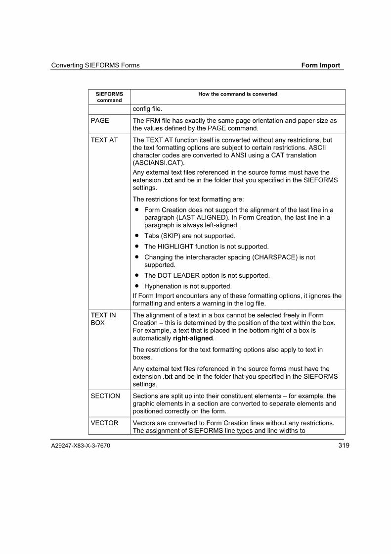
Converting SIEFORMS Forms Form Import
A29247-X83-X-3-7670 319
SIEFORMScommand
How the command is converted
config file.
PAGE The FRM file has exactly the same page orientation and paper size asthe values defined by the PAGE command.
TEXT AT The TEXT AT function itself is converted without any restrictions, butthe text formatting options are subject to certain restrictions. ASCIIcharacter codes are converted to ANSI using a CAT translation(ASCIANSI.CAT).Any external text files referenced in the source forms must have theextension .txt and be in the folder that you specified in the SIEFORMSsettings.
The restrictions for text formatting are:• Form Creation does not support the alignment of the last line in a
paragraph (LAST ALIGNED). In Form Creation, the last line in aparagraph is always left-aligned.
• Tabs (SKIP) are not supported.• The HIGHLIGHT function is not supported.• Changing the intercharacter spacing (CHARSPACE) is not
supported.• The DOT LEADER option is not supported.• Hyphenation is not supported.
If Form Import encounters any of these formatting options, it ignores theformatting and enters a warning in the log file.
TEXT INBOX
The alignment of a text in a box cannot be selected freely in FormCreation � this is determined by the position of the text within the box.For example, a text that is placed in the bottom right of a box isautomatically right-aligned.
The restrictions for the text formatting options also apply to text inboxes.
Any external text files referenced in the source forms must have theextension .txt and be in the folder that you specified in the SIEFORMSsettings.
SECTION Sections are split up into their constituent elements � for example, thegraphic elements in a section are converted to separate elements andpositioned correctly on the form.
VECTOR Vectors are converted to Form Creation lines without any restrictions.The assignment of SIEFORMS line types and line widths to

Form Import Converting SIEFORMS Forms
320 A29247-X83-X-3-7670
SIEFORMScommand
How the command is converted
corresponding Form Creation settings is based on the settings in theconfig file S2FCFG.INI.
SIEFORMS Converter Abend Messages
Errors that cause abnormal termination of the conversion of a SIEFORMS form areentered in the log file. The table below lists the abnormal end messages that theconverter can enter in the log:
Abend no. Message text, Recommended course of actionA002 Unable to find font library.
Check the setting for the font library in the Form Creation settings.
A003 Unable to find font mapping.
Create a font mapping table using the "Edit Font Mapping Table" functionon the "Settings" tab.
A004 Font library defective
The Form Creation font library may be corrupted. Re-generate it.
A005 Unable to find CAT file or path.
Check the path you have set for the CAT file in the SIEFORMS settingsand verify that this CAT file actually exists.
A006 No input file specified
Specify an input file and restart the converter.

Converting SIEFORMS Forms Form Import
A29247-X83-X-3-7670 321
SIEFORMS Converter Error Messages
If the SIEFORMS converter encounters errors when converting a form, it enters them inthe log file. The table below lists the error messages that the converter can enter in thelog:
Error no. Message text, Recommended course of actionAFE014 Unable to locate output file or path!
Check the settings for the output folder. Verify that:- you have write access rights to this folder� there is enough space free on disk� no write-protected file of the same name exists
AFE016 Unable to create SECTION temp file.
The converter has encountered problems creating or editing a temporaryfile required for buffering SECTION data. There might not be enoughspace free on your hard disk. Free some space on your hard disk andstart the conversion again.
EFE020 Error opening text file.
The converter is unable to open an external text file. Check the path youhave set for external text files in the SIEFORMS settings, and verify thatthe requested text file actually exists.
FRL001 Error opening FRL file.
The converter is unable to open the line style definition file. Verify thatyou have set the correct path and name for this file in the SIEFORMSsettings.
FRP001 Error opening FRL file.
The converter is unable to open the fill pattern definition file. Verify thatyou have set the correct path and name for this file in the SIEFORMSsettings.
AME<n> Nor enough memory.
<n> = three-digit number (internal identification)An attempt to request memory from the system has failed because thereis not enough RAM free on your PC. In serious cases, the conversion isaborted � in other cases, the converter skips the current SIEFORMScommand. Close other applications and start the conversion again.
AFE040 Unable to find bitmap file or path.

Form Import Converting SIEFORMS Forms
322 A29247-X83-X-3-7670
Error no. Message text, Recommended course of action
The converter is unable to open an external image file. Check the imagepath in the SIEFORMS settings, and verify that the requested file actuallyexists.
AFE041 Bitmap file corrupt.
Please check the image file.
AFE042AFE043
Unable to create bitmap temp file.
The converter has encountered problems creating or editing a temporaryfile required for buffering image data. There might not be enough spacefree on your hard disk. Free some space on your hard disk and start theconversion again.
ETXT01 Error in text element.
A text element was not completed correctly, or it contains an invalidcombination of inverted commas (") and/or apostrophes (').

Converting SIEFORMS Forms Form Import
A29247-X83-X-3-7670 323
SIEFORMS Converter Warnings
If the SIEFORMS converter encounters problems for which it can execute aworkaround, it enters these problems in the log file as warning messages. The tablebelow lists the warning messages that the converter can enter in the log..
Warning no. Warning textExplanation
WISP001 'Interword Space' is not supported.
WDOL001 'Dot Leader' is not supported.
WLST001 'Last Aligned' is not supportedThe last line in a paragraph is always aligned left.
WTAB001 Tabs are not supported
WCOL001 Colour attributes are not supported
WCSP001 'Character Spacing' is not supported
WHIL001 Highlighting is not supported
WSTR001 Hyphenation is not supported.Hyphens are ignored and removed from the text.
WSCL001 Scaling of graphics is not supportedGraphics are always converted one-to-one.
WSHA001 No value for shading found in INI fileVerify that the INI file S2FCFG.INI (in Windows folder) contains anassignment for the fill pattern index being used.
WLWD001 No value for line width found in INI fileVerify that the INI file S2FCFG.INI (in Windows folder) contains anassignment for the line width being used.
WLTY001 No value for line type found in INI fileVerify that the INI file S2FCFG.INI (in Windows folder) contains anassignment for the line style being used.
WUNE001 Unexpected end-of-file (no END statement or 0x00 in the next statement)Check the SIEFORMS source. If only the END statement is missing, youcan ignore the warning. Otherwise, the source is damaged andconversion cannot continue.
Form Import Parameter Files
324 A29247-X83-X-3-7670
Other parameter files
INI Files
The INI files define the defaults to be used when the program is launched.
Form Import works with the following INI files:
O2FCFG.INI defaults for the OGL converter,
XFXCFG.INI defaults for the Form Import program and LCDS converter,
S2FCFG.INI defaults for the SIEFORMS converter.
COD Files
LCDS forms use different character codings depending on the country. To identify thescheme being used, the converter has to be notified of the name of the country. Youset this parameter in the "Code Mapping" field on the Settings tab. The internalconversion of LCDS code to ASCII is made on the basis of this setting.
Your code mapping setting references a file with the extension COD in the Windowssystem folder. A COD file is a text file containing one line for each character in thefollowing format:
AB = MN
MN is the ASCII equivalent (hex) of the LCDS code point AB (also hex).
The value in the first left column should be 00 and in the last FF. The value incrementsby 1 in each line.
Example:
00=00
01=00
�.
�.
FE=B5
FF=20

Parameter Files Form Import
A29247-X83-X-3-7670 325
You can define your own COD files. These should be placed in the Windows systemfolder. If you do create your own COD files, you should make the necessary changes tothe [Code Mapping] section in XFXCFG.INI.
CAT Files
A conversion table is required to convert the characters in the texts in OGL andSIEFORMS sources. The composition of these tables is much the same as that of aCAT file used by Océ printing systems in L mode. The file name extension is .CAT.
The package ships with a default CAT file called ASCIANSI.CAT. This is used forconverting text files with ASCII coding (DOS text) to ANSI (as used by Windowsprograms, including Form Creation). A custom-defined CAT is also a way of correctingany corruption of the character codes that might arise when a file is transferred from ahosts system to a PC. A CAT file must always be 261 bytes long. There is a 5-bytestring at the beginning of the file, typically X'0105D60F00'. Then come 255 bytes ofcharacter codes. If you do not need to convert the character codes, you should selectthe CAT file SET0000.CAT (linear CAT) which ships with the program package.
You set the name and path of the CAT file on the "Settings" tab for the source formatsOGL and FSL.


Colour Mapping
A29247-X83-X-3-7670 327
COLOURMAPPING


Introduction Colour Mapping
A29247-X83-X-3-7670 329
Colour Mapping
The Colour Mapping Table ResourceA colour mapping table (CMT) is used when printing to replace the colours of the originaldocument with colours better suited for the print process. The document itself does nothave to be changed for colour mapping with the help of a CMT.
Examples of when colour mapping tables are used:
• when you have created a document with other software and it contains particularobjects you want to print in particular colours
• when documents are to be printed on different printing systems and still produce thesame print image
• when document appearance is to remain unchanged even after moving to a differentprinter.
The CMT, along with an object ID and name, is transferred to the printing system in anobject container as a non-printing resource. When a document is printed, the CMT canbe called from a document-specific resource package or from the resource library. Astandard CMT can also be assigned to the output process.
The table itself consists of a table header and, provided it is not a reset table, one ormore repeating groups.
Whether the table is a genuine mapping table or a reset table that switches off themapping process is defined in the table header.Repeating groups define which colour is to be substituted for which colour of the originaldocument during printing. Colour mapping requires that at least one source group andone target group is present in a CMT. The colours in the original document are listed inthe source group; the target group lists the colours to be printed instead of the originalcolours.
Each target group is assigned to a source group by means of a group ID, a binary numberfrom 1 to 127. Several source groups can be assigned to the same target group. Thismeans several source groups can be present with the exact same ID, but a target groupID may occur only once.

Colour Mapping Introduction
330 A29247-X83-X-3-7670
The CMT first lists all source groups by ID in ascending order and then all target groupsby ID in ascending order.
Object container
Table header
Target group
ID = 1
ID = 1(2)
ID = 2
ID = 1(3)
ID = 3
ID = 1
Source group
Source group
Source group
Source group
Target group
Target group ...
ID = 2
Repeatinggroups
Target group
Source group ...
ID = 3Source group
Fig. 168: CMT diagram
A CMT called during printing remains active until another mapping table or reset table isinitiated. A reset table switches off the colour mapping process.
See also section �CMT Syntax�.

Introduction Colour Mapping
A29247-X83-X-3-7670 331
Program functionsThe Colour Mapping program enables you to create colour mapping tables (CMT) quicklyand easily. The graphical user interface makes for intuitive working with the program.
The Colour Mapping user interface consists of the main Colour Mapping window andspecific dialog boxes for creating new CMTs and repeating groups. System dialog boxesare activated to open an existing CMT (Open), to save a CMT under a particular name ina specified directory (Save as), as well as to define a colour to be included in the mappingtable.
Your Colour Mapping specifications for colour mapping are automatically converted to aconsistent colour mapping table using specified syntax.
The CMT is saved in a file, and is then available for use in a print job. It can either beincluded with the job as a resource or transferred to the printing system using theappropriate software. You may have to convert the CMT from binary to TRANS formatusing the BT2 program.
Colour Mapping is a component of the �Océ Document Designer Standard Suite�.

Colour Mapping User Interface
332 A29247-X83-X-3-7670
User Interface
Main Window
In addition to the buttons Exit, Help, Info and a button for choosing the interfacelanguage, Colour Mapping�s main window is divided into the two dialog areas �MappingTable� and �Repeating Groups�.
Fig. 169: Main Colour Mapping window

User Interface Colour Mapping
A29247-X83-X-3-7670 333
ExitClicking the Exit button closes the main window and ends the Colour Mapping program.
HelpClicking the Help button opens the online help.
InfoClicking the Info button opens the �About Colour Mapping� dialog box and displays theversion number, product number and serial number.
LanguageIn the �Language� selection field you can choose the language you want the ColourMapping user interface to use. Clicking u displays a list of available interface languagesfrom which you can choose.
The �Mapping Table� Dialog AreaThe �Mapping Table� dialog area (group box) displays the functions enabling you to opena mapping table for editing, to create a new mapping table, and to save the currentmapping table.
Fields are provided in this dialog area for changing the table ID and table name.
�Table ID� fieldThe table ID for the current CMT is displayed as a number between 1 and 65534.
You can change the ID in the dialog field.
The table ID is entered in the table header (binary in byte 2 and 3 � also see �CMTSyntax�).

Colour Mapping User Interface
334 A29247-X83-X-3-7670
�Table Name� fieldThe name of the current CMT is displayed here. You can change the name in this dialogfield. The name can be a maximum of 8 characters and may include letters and numbers.
The table name is entered in the header of the CMT object container (BOC).
The table name specified here may differ from the file name that is used to store the CMTfile. It is recommended to use the same name in both cases.
If the resulting CMT is later on transferred to a print server or host system (for dynamicdownload via Job Control) it is there identified with it�s file name. A standardised methodto differ the various resources on server systems is to assign a unique name prefix for thedifferent types of resources. For Colour Mapping Table the prefix M1 is used.
If the resulting CMT is to be used directly on the printer it has to be copied to a standard1.44 MB Floppy Disk and loaded onto the printer�s hard with the help of the printer�scontrol panel. In this case the CMT file name must have a file extension of .CMT. Once itis stored on the printer�s hard disk you can find and select the CMT with the internal tablename specified here. (see also �Save As� Button)
�Open� buttonClicking the Open button displays the �Open� dialog box where you can navigate to thedirectory containing CMT files and open a table.
Fig. 170: �Open� dialog box

User Interface Colour Mapping
A29247-X83-X-3-7670 335
�New� buttonClicking the New button displays the �New Colour Mapping Table� dialog box where youcan create a CMT. Fields are provided for defining the table ID, type and name of the newtable (see description of dialog fields above) . Clicking OK saves the new table, which youcan then edit in the main window.
Fig. 171: �New Colour Mapping Table� dialog box
�Save� buttonClicking the Save button saves the current CMT in a file. A modified CMT is automaticallysaved to the file that you opened.
Clicking the Save button when creating a new table displays the �Save as� dialog boxwhere you can select or enter the directory and file name to save under.
�Save As� buttonClicking the Save As button displays the �Save As� dialog box; here, you can specify thedirectory to save the current table and enter a file name. This allows you to save amodified table under a different name; the original table remains unchanged.
When you want to save a new CMT, clicking the Save button also displays the �Save As�dialog box.

Colour Mapping User Interface
336 A29247-X83-X-3-7670
Fig. 172: �Save As� dialog box
The file name specified here may differ from the table name specified with the table namefield (see �table name field� above). It is recommended to use the same name in bothcases.
If the resulting CMT is later on transferred to a print server or host system (for dynamicdownload via Job Control) it is there identified with it�s file name. You have to obey theknown restrictions for file names on host systems (1-8 characters, first character not anumeric, no file extension). A standardised method to differ the various resources onserver systems is to assign a unique name prefix for the different types of resources. ForColour Mapping Table the prefix M1 is used.
If the resulting CMT is to be used directly on the printer (resident) it has to be copied toa standard 1.44 MB Floppy Disk and loaded onto the printer�s hard with the help of theprinter�s control panel. In this case the CMT must have a standard DOS name (1-8characters followed by a file extension of .CMT) . Once it is stored on the printer�s harddisk you can find and select the CMT with the internal table name.
Colour Mapping stores the CMT in binary format (AFPDS). If for some reason the TRANS-Format is required, the program B2T.EXE (Utilities) is available to convert the binaryformat to TRANS format.

User Interface Colour Mapping
A29247-X83-X-3-7670 337
The �Repeating Groups� Dialog AreaThis dialog area is active only if you have opened or created a new CMT. If you haveopened or created a reset table, this area is not relevant.
In the �Repeating groups� dialog area you can create, modify and delete a repeatinggroups within the CMT.
�Repeating Group ID� fieldDisplayed in the �Repeating Group ID:� selection field is the ID of the current source group,which appears under �Source Colour values�. The corresponding target group can be seenunder �Target Colour Values�. If a CMT contains several source groups with the same ID,the repeat factor is displayed with the ID, enclosed in parentheses. (Example: 1(3) meansthe third source group with the ID 1.) For target groups, each ID may occur only once.
Fig. 173: �Repeating Group ID� field
Clicking u displays the IDs of all source groups that have been created in the currenttable. You can then select a group to display or modify.
�Object Type� displayThis area tells you which object types the current source group is valid for. You make thisspecification for a repeating group when you create a new group.
Colour Mapping User Interface
338 A29247-X83-X-3-7670
�Source Repeating Group� Area
Colour Space�Colour Space� displays the name of the colour space as well as the size (number of bits)of its representation components for the current repeating group.
You specify the colour space when you create a new repeating group.
The system recognises the colours of the following representation models in the originaldocument:
• Highlight colour
• Standard OCA colour
• GOCA pattern fill
Source Colour ValuesThe definition components of the colours in the source group are listed here inhexadecimal form.
A line in the target colour list is assigned to each line in the source colour list; thisspecifies the colour to substitute for the original colour when printing.
Clicking u scrolls the list up and tscrolls the list down. The list of target colours isscrolled at the same time. The scroll bar is not available for use in this display field.
�Target Repeating Group� Area
Colour Space�Colour Space� displays the name of the colour space as well as the size (number of bits)of its representation components for the current repeating group.
You specify the colour space when you create a new repeating group.
The following models can be used for representing target colours:
• Highlight colour
• CMYK
• RGB
• CIELAB

User Interface Colour Mapping
A29247-X83-X-3-7670 339
Target Colour ValuesThe definition components of the colours in the target group are listed here inhexadecimal form. Each line in the target colour list corresponds to a line in the sourcecolour list.
Clicking u scrolls the list up and tscrolls the list down. The list of source colours isscrolled at the same time. The scroll bar is not available for use in this display field.
�New Repeating Group� buttonClick the New button in the repeating group dialog area to open the �New RepeatingGroup� dialog box. Use this to create a new source group and, if necessary, a new targetgroup (see �New Repeating Group� dialog box).
Fig. 174: �New Repeating Group� dialog box
�Delete Repeating Groups� buttonClick the Delete button to delete the current source group. If the current origin ID ispresent only once, the corresponding target group is also deleted.
The Delete button is active only if more than one source group is present.
Colour Definition FieldsIn the dialog fields below the display lists for source and target colours you can definenew colour substitutions and add them to the list, or change existing definitions. You canselect a defined colour in the colour selection field.
Colour Mapping User Interface
340 A29247-X83-X-3-7670
If the colour you want to replace or use is not among the defined colours, you can define acolour yourself. Simply select New colour and the �Colour� system dialog box isdisplayed. Here you can specify a RGB-model primary colour or define a coloursynthesis. Applying the new colour in Colour Mapping is only possible if the specifiedcolour model supports the new colour.
Use the component dialog fields to enter the representation components of the colourcorresponding to the specified colour model. Decimal values are converted to binaryvalues when applied to the table and represented as hexadecimal values in the displayfields.
To display a colour mapping from the current repeating group for editing in the dialogboxes, click the name of the original colour in the relevant line. Within the framework ofthe specified colour model, you can then change the content of the marked line in thedialog fields.
Clicking the Replace button overwrites the marked line in the colour list with the data inthe dialog fields. Clicking the Add button adds the definitions from the dialog fields to thecurrent list.
�Replace� buttonClicking the Replace button overwrites the marked line in the colour list with the contentof the dialog field colour definitions.
�Add� buttonClicking the Add button adds the colour definitions in the dialog fields to the colour lists(source and target colours).
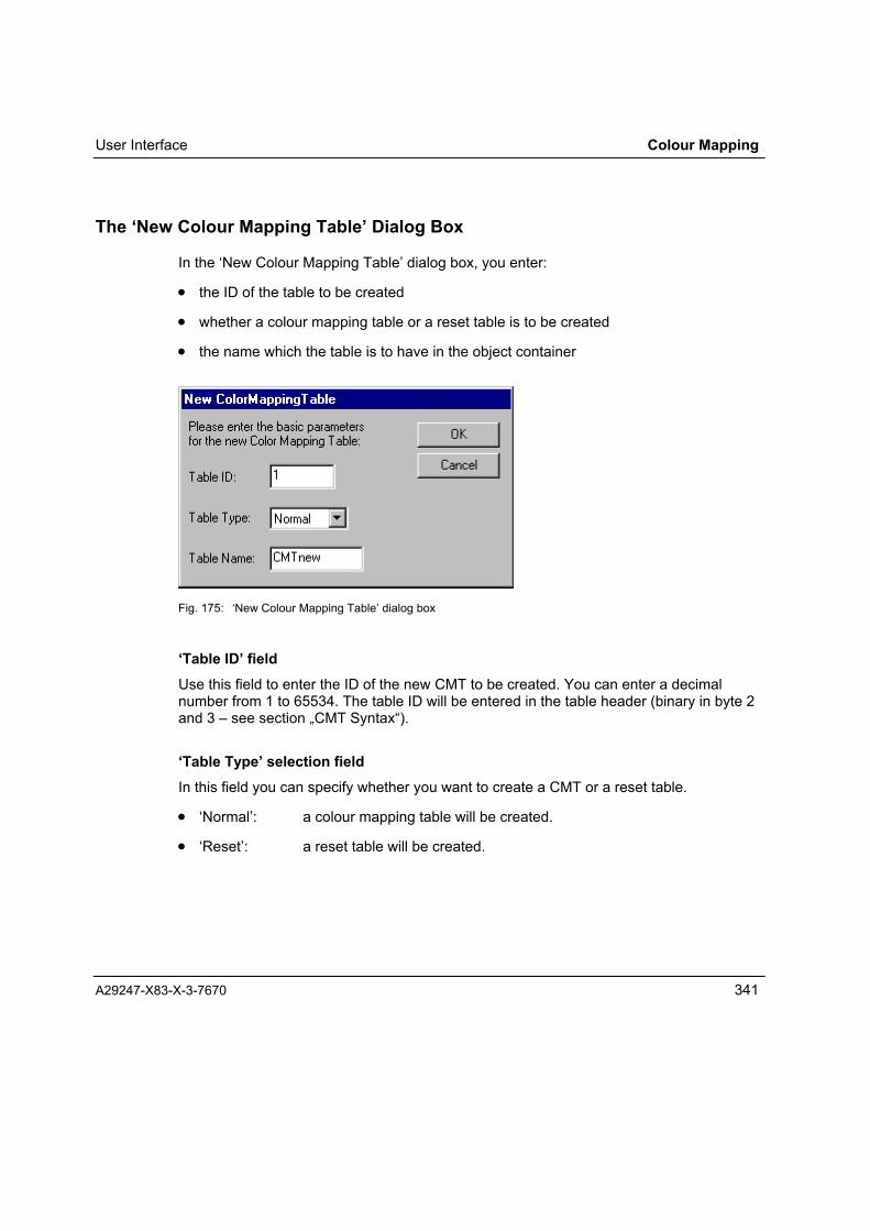
User Interface Colour Mapping
A29247-X83-X-3-7670 341
The �New Colour Mapping Table� Dialog Box
In the �New Colour Mapping Table� dialog box, you enter:
• the ID of the table to be created
• whether a colour mapping table or a reset table is to be created
• the name which the table is to have in the object container
Fig. 175: �New Colour Mapping Table� dialog box
�Table ID� fieldUse this field to enter the ID of the new CMT to be created. You can enter a decimalnumber from 1 to 65534. The table ID will be entered in the table header (binary in byte 2and 3 � see section �CMT Syntax�).
�Table Type� selection fieldIn this field you can specify whether you want to create a CMT or a reset table.
• �Normal�: a colour mapping table will be created.
• �Reset�: a reset table will be created.

Colour Mapping User Interface
342 A29247-X83-X-3-7670
�Table name� fieldHere you can specify a name with up to 8 letters and numbers that will be entered in theCMT object container.
The table name is not the file name under which the CMT is saved. However, it is a goodidea to save the CMT file using the same name as the table name (see The �MappingTable� Dialog Area).
�OK� buttonClicking the OK button closes the �New Colour Mapping Table� dialog box; the new CMTis now defined. You return to Colour Mapping�s main window; if the table you defined wasa colour mapping table, you can now define the colour mapping.
If you defined a reset table, no further steps are possible or necessary.
�Cancel� buttonClicking the Cancel button closes the �New Colour Mapping Table� dialog box; no newCMT is defined.
The �New Repeating Group� Dialog Box
In the �New Repeating Group� dialog box, you can specify:
• the ID of the repeating group to be created in the CMT
• which types of object in the original document are to be colour mapped
• the colour space used to represent the colours in the original document
• the colour space to be used to describe the target colours.
Some colour spaces also allow you to specify the size of individual representationcomponents.

User Interface Colour Mapping
A29247-X83-X-3-7670 343
Fig. 176: �New Repeating Group� dialog box
�Repeating Group ID� selection fieldThis field shows the ID for the new repeating group as a decimal number between 1 and127. The ID is valid for the source repeating group as well as for the target repeatinggroup.
When the dialog box is opened, the next free ID (i.e. one number higher than the last) isentered automatically.
You cannot enter your own definition of the group ID. You can, however, select a ready-defined ID from the list. This enables you to define an additional source group for anexisting target group. This procedure does not allow you to change the target group data.
�Object Type� selection fieldHere you can select the object type(s) in the original document to which the repeatinggroup is to apply. The object types are listed with their names and, in parentheses, theselection codes that are entered in the mapping table.
The choices are:
• Object area (code: 0x6b)
• IM image data (code: 0x7b)
• PTOCA data (code: 0x9b)
• Page presentation (code: 0xaf)

Colour Mapping User Interface
344 A29247-X83-X-3-7670
• GOCA data (code: 0xbb)
• Overlay presentation space (code: 0xdf)
• BCOCA data (code: 0xeb)
• All PTOCA, IM, IOCA, GOCA and BCOCA (code: 0xfe)
• All (code: 0xff)
The �All� entry (code: 0xff) for all object types is the default.
The �Source Repeating Group� Dialog Area
�Colour Space� selection fieldFrom the list, select the colour space used to describe the colours in the originaldocument.
The choices are:
• Highlight colour
• Standard OCA colour
• GOCA pattern fill
�Component Size� Selection Fields 1-3These fields display the size of the representation components in number of bits.
Component size is fixed for the colour spaces Standard OCA colour and GOCA patternfill.
For highlight colour you can specify whether representation components 2 and 3 use 8bits.
The �Target Repeating Group� Dialog Area
�Colour Space� Selection FieldHere you can select the colour space to be used to represent the target colours.
The choices are:
• Highlight colour
• CMYK
• RGB

User Interface Colour Mapping
A29247-X83-X-3-7670 345
• CIELAB
�Component Size� Selection Fields 1-4These fields display the size of the representation components in number of bits.
Component size is fixed for the CMYK, RGB and CIELAB colour spaces.For highlight colour you can specify whether representation components 2 and 3 are touse 8 bits.
The �Keep existing one� check box indicates that an existing target group you are using foranother source group will remain unchanged.


Working with Colour Mapping Colour Mapping
A29247-X83-X-3-7670 347
Working with Colour Mapping
Creating a New CMT
⇒ Click New in the �Mapping Table� dialog area of Colour Mapping�s main window.This displays the �New Colour Mapping Table� dialog box.
Fig. 177: �New Colour Mapping Table� dialog box
⇒ In the �Table ID:� field, enter a number from 1 to 65534 to identify your table.
⇒ Choose a table type from the �Table Type� list: �Normal� to define a CMT, �Reset� tocreate a reset table.
⇒ Enter a name for your table in the �Table Name:� field. The name can be a maximumof 8 characters and may include letters and numbers.
⇒ Click OK to confirm the �New Colour Mapping Table� dialog box.
If you selected �Normal� for the table type, you can now create repeating groups in ColourMapping�s main window for colour mapping definitions.
Opening an Existing CMT
⇒ Click Open in the �Mapping Table� dialog area of Colour Mapping�s main window.This displays the �Open� dialog box.

Colour Mapping Working with Colour Mapping
348 A29247-X83-X-3-7670
Fig. 178: �Open� dialog box
⇒ Select a CMT file. No file type is specified for CMT files, i.e. no file extensions. Anattempt to open a file that does not contain a colour mapping table results in the errormessage �No valid BOC in file� (BOC=Begin Object Container).
Fig. 179: Warning: the file does not contain a valid object container
⇒ Click the Open button to open the selected file.
You can now edit the selected table in Colour Mapping�s main window.

Working with Colour Mapping Colour Mapping
A29247-X83-X-3-7670 349
Saving a CMT
⇒ Clicking the Save button saves the current CMT in a file. If you have not yet given thenew CMT a file name (�no file� appears in the application title bar), the �Save As� dialogbox opens for you to select a directory and enter a file name.
Colour Mapping allows any file name in accordance with Windows file-namingconventions. It is recommended that you use the mapping table name as the filename (see The �Mapping Table� Dialog Area).
If the CMT has already been saved once (the current path and file name appear in theapplication title bar), clicking Save saves the current file and overwrites the filecontent with the current CMT without prompting you.
Fig. 180: �Save As� dialog box
⇒ Clicking the Save As button opens the �Save As� dialog box even if the current CMThas already been saved to file. This allows you to save the current CMT to a differentfile; the original CMT remains unchanged.

Colour Mapping Working with Colour Mapping
350 A29247-X83-X-3-7670
Creating a New Repeating Group
⇒ Click New in the �Repeating Groups� dialog area to open the �New Repeating Group�dialog box.
Fig. 181: �New Repeating Group� dialog box
Based on the repeating groups already created, the next available ID number for thenew repeating group is automatically displayed in the �Repeating Group ID:� field.
⇒ If you are using an existing target group and only want to define a new source group,select the desired repeating group ID in the field.
⇒ In the �Object Type:� list, select the object type or group of object types of the originaldocument to be colour mapped. The default is �All� (CMT code: 0xff; see section �CMTSyntax�).
⇒ Select the colour space for the source group, i.e. the colour space used to describethe colours in the original document.
⇒ Select the colour space for the target group, i.e. the colour space to be used todescribe the colours for the print output.
If you want to define a new source group for an existing target group (i.e. if you haveselected an existing repeating group under �Repeating Group ID:�), the colour spaceof the target group is already fixed and you cannot change it.
⇒ If you have selected �Highlight Colour� as the colour space for the original or targetgroup, you can specify the size of components 2 and 3 (0 or 8 bits; see �HighlightColour� space definition).

Working with Colour Mapping Colour Mapping
A29247-X83-X-3-7670 351
⇒ Click OK to confirm the �New Repeating Group� dialog box. This creates the newrepeating group and now you can enter the colour mapping definitions in ColourMapping�s main window.
If you selected an existing repeating group in order to assign a new source group to adefined target group, the target group now appears in the main window. The sourcegroup display is empty.
Selecting a Repeating Group for Editing
⇒ Select the ID of the repeating group you want to edit from the �Group ID:� field in therepeating group dialog area. After you have selected the ID, the repeating group isdisplayed in the �Source Repeating Group� and �Target Repeating Group� areas of thewindow.
Fig. 182: Repeating group selection
Deleting a Repeating Group
⇒ Select the repeating group you want to delete by selecting the group ID in the�Repeating Group ID:� selection field.
⇒ Click the Delete button to delete the selected repeating group.

Colour Mapping Working with Colour Mapping
352 A29247-X83-X-3-7670
Defining and Adding Colour Mapping
⇒ Select the name of the source colour to be mapped for printing from the list. If thecolour is not available in the list, you must create a new definition (see �Creating aNew Colour�).
⇒ Enter the values for the representation components corresponding to the sourcegroup�s colour space (see Colour Spaces: Highlight Colour, Standard OCA Colour,GOCA Pattern Fill).
⇒ From the list of target colours, select the one to replace the source colour whenprinting. If the colour is not available in the list, you must create a new definition (see�Creating a New Colour�).
⇒ Enter the values for the representation components of the source colourcorresponding to the colour space (see Colour Spaces: Highlight Colour, StandardOCA Colour, GOCA Pattern Fill).
⇒ Enter the values for the representation components of the target colour correspondingto the colour space of the target group (see Colour Spaces: Highlight Colour, CMYK,RGB, CIELAB).
⇒ Click the Add button. The new definition is appended to the list and appears as thelast line in the display fields for the source and target colours.

Working with Colour Mapping Colour Mapping
A29247-X83-X-3-7670 353
Creating a New Colour
Fig. 183: �Create New� colour selection
⇒ Select �Create New� in the list of colours to open the �Colour� dialog box.
Fig. 184: �Colour� dialog box

Colour Mapping Working with Colour Mapping
354 A29247-X83-X-3-7670
• You can get context-sensitive help by clicking the right mouse button in the �Colour�dialog box.
⇒ Select the desired colour from the choice of basic colours or from the user-definedcolours.
⇒ Click OK. The new colour is added as �New colour� to the list defining colour mapping.You can give the new colour a name in this list.
If the colour you want to specify for colour mapping is not among the selection, you canmake a custom definition.
⇒ Click Define Custom Colours >> to expand the dialog box to include colourdefinition.
⇒
Fig. 185: �Colour� dialog box, defining colour
⇒ Point the mouse at the colour you want on the colour matrix and click the left mousebutton. This selects one of 240 colours and defines its saturation with a value of 0 to240.

Working with Colour Mapping Colour Mapping
A29247-X83-X-3-7670 355
You can also define the colour by specifying the colour number and saturation valueIn the �Colour:� field enter a number from 0 to 239; in the �Sat:� field enter a value from0 to 240.
You can also define the colour by specifying the red, green and blue values. Entercolour values from 0 to 255 in the �Red�, �Green� and �Blue� fields.
⇒ Specify the colour�s luminosity by sliding the arrow next to the luminosity bar (right ofthe colour matrix) up or down, or you can enter a luminosity value from 0 to 240 in the�Lum:� field.
⇒ Click the Add Colour button. The colour is added to the next available field in the 16fields for user-defined colours. If all 16 fields are in use, the new colour overwrites thecolour in the first field; additional newly defined colours successively overwrite thefields that follow.
You can change user-defined colours at any time. This is how:
⇒ click the user-defined colour to be changed
⇒ change the colour specifications for saturation and luminosity
⇒ click the Add Colour button
Changing Colour Mapping
⇒ Click the source colour in the repeating group display field; the source and targetcolours of the corresponding line appear in the dialog field for defining colourmapping.
⇒ Change the specifications in the dialog fields as needed.
⇒ Click the Replace button to overwrite the marked line in the display field.

Colour Mapping Working with Colour Mapping
356 A29247-X83-X-3-7670
Deleting Colour Mapping
⇒ Click the right mouse button on the name of the source colour whose colour mappingyou want to delete. The Delete button appears.
Fig. 186: Delete button
⇒
⇒ Click the Delete button.

Examples Colour Mapping
A29247-X83-X-3-7670 357
Examples
Example 1: Printing a monochrome application with colour
You have an old monochrome application that contains - apart form text - also a signature(in IOCA format). You like to print the signature with the highlight colour on an OcéPagestream 200 DSC with blue toner for the additional colour. You don�t have to changeyour application for this. Instead you use a CMT that maps the IOCA objects to HLC1(Highlight Colour, Component1=1). All other elements are automatically printed with HLC0(Highlight Colour, Component1=0), i.e. black.
Fig. 187: Colour mapping Example 1
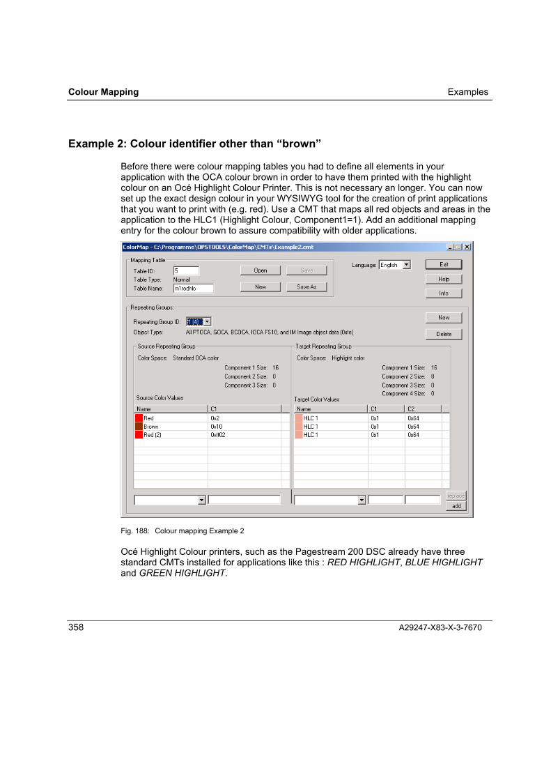
Colour Mapping Examples
358 A29247-X83-X-3-7670
Example 2: Colour identifier other than �brown�
Before there were colour mapping tables you had to define all elements in yourapplication with the OCA colour brown in order to have them printed with the highlightcolour on an Océ Highlight Colour Printer. This is not necessary an longer. You can nowset up the exact design colour in your WYSIWYG tool for the creation of print applicationsthat you want to print with (e.g. red). Use a CMT that maps all red objects and areas in theapplication to the HLC1 (Highlight Colour, Component1=1). Add an additional mappingentry for the colour brown to assure compatibility with older applications.
Fig. 188: Colour mapping Example 2
Océ Highlight Colour printers, such as the Pagestream 200 DSC already have threestandard CMTs installed for applications like this : RED HIGHLIGHT, BLUE HIGHLIGHTand GREEN HIGHLIGHT.

Examples Colour Mapping
A29247-X83-X-3-7670 359
Example 3: To change the toner does not mean to change all colour
Your application contains a red logo (IOCA with OCA colour red) and a blue signature(IOCA with OCA colour blue). When you are printing with a red toner on your Pagestream200 DSC only the logo shall be printed with the red toner. When you are printing with ablue toner the logo shall not be printed with the blue toner but with the black one.You control this behaviour with two different CMTs that you activate whenever you changethe toner on your printer.
Fig. 189: Colour mapping Example 3
RREEDD
BBLLUUEE

Colour Mapping Examples
360 A29247-X83-X-3-7670
Example 4: Grey scales or �black and white�
You have a monochrome printer and print an application with blue and red images (IMimages with OCA definitions) and a yellow background area (Object Area shading withOCA definitions). With the support of grey scales in the new Océ Pagestream printersyou may get a result that is not quite what you wanted. You have the possibility to switchback to the old Black and White behaviour or to adjust the grey scale mappings bymeans of a CMT of your own. If you want it Black and White use a CMT that maps allobject data to HLC0 (Highlight Colour, Component 1=0) with full coverage (component2=100). In a second repeating group however you map all area definitions to HLC0(Highlight Colour, component 1=0) with coverage 0% (Component2=0) i.e. to white.
Fig. 190: Colour mapping Example 4
Océ monochrome printers have a standard CMT installed for this: CLASSIC BLACK

Examples Colour Mapping
A29247-X83-X-3-7670 361
Example 5: Another way to print diagrams
You have an application that containsdiagrams with GOCA Fill Patterns. You wouldnow like to have shadings of black andhighlight colour in the diagram instead of thefill patterns.All you have to do is to create a CMT. Therepeating group within the CMT uses sourcecolour space GOCA Pattern Fill and the targetcolour space Highlight Colour. For each fill pattern you add an entry that specifiescomponent 1 (C1=0 black, C1=1 colour) as well as component 2 (i.e. the desiredcoverage in percent). If you also activate component 3 in the repeating group you are ableto define a mixture between HLC0 (black) and HLC1(colour) additionally.
Fig. 191: Colour mapping Example 5

Colour Mapping Examples
362 A29247-X83-X-3-7670
Example 6: Highlight Colour to another Highlight Colour
You have an application consisting of text and IOCA images, designed for an InfoPrint4005 Hi-Lite printer. In this application the colour values are already defined with thecolour space Highlight colour, e.g. HLC=1 (for red colour) and HLC=2 (for blue colour).You now want to print this application on an Océ PageStream 200 DSC and use a redtoner for the additional colour. With a CMT it is also possible to convert Highlight colour toother Highlight colour information.You define two repeating groups � one for the PTOCA text � one for the IOCA images.You convert the HLC1 definitions to HLC1 (red stays red) and � depending on the type ofobject � you convert the HLC2 definitions either to HLC0 (black) or HLC1(red).
Fig. 192: Colour mapping Example 6

Examples Colour Mapping
A29247-X83-X-3-7670 363
Example 7: Conversion to CMYK
In the future you may have an AFP full colour printer. The application you are printing nowon a Highlight Colour printer can be used on this new printer without any modification.You just have to tell the new printer how it shall map the �old� OCA colour spacedefinitions to appropriate new CMYK colour definitions. Again a task for a colour mappingtable. The CMT you would have to define then could look like this:
Fig. 193: Colour mapping Example 7
Remark: Transformation from OCA to CMYK is only possible with full colour machines.
Note: You can find all CMTs of the listed examples in the Colour Mapping installationdirectory.

Colour Mapping CMT Syntax
364 A29247-X83-X-3-7670
CMT Syntax
Table Header
Position Type Name Value range Description0-1 Binary TBLlngth 6-65535 Table length2-3 Code TBLid 1-65535 Table ID4 Code TBLtpe
0x010x81
Table typeColour mapping tableReset table
5 Reserved, must be 0A colour mapping table (table type 0x01) must contain at least one source and onetarget repeating group.
Source Repeating Group
Position Type Name Value range Description0-1 Binary RGLngth 30-(n+1) Length of the repeating group2 Binary RgId 1-127 ID of the repeating group3 Code RGTpe 0x01
All othervalues arereserved
Type of the repeating groupSource repeating group
4 Code ColSpce0x060x400x50All othervalues arereserved
Colour spaceHighlight colour spaceStandard OCA colour spaceGOCA pattern fill space
5-8 Reserved, must be 09 Binary ColSize1 0x08
0x10Number of bits in component 1,see colour model definitions
10 Binary ColSize2 0x00,0x08
Number of bits in component 2,see colour model definitions
11 Binary ColSize3 0x00,0x08
Number of bits in component 3,see colour model definitions
12 Reserved, must be 0

CMT Syntax Colour Mapping
A29247-X83-X-3-7670 365
13 Code ObjSel0x6b0x7b0x9b0xaf0xbb0xdf0xeb0xfb0xfe
0xff
All othervalues arereserved
Choice of source object typesObject areaIM image dataPTOCA dataPage representation levelGOCA dataOverlay representation levelBCOCA dataIOCA dataAll data: PTOCA, GOCA, BCOCA,IOCA, FS 10 and IM image objectdataAll objects, object areas andrepresentation levels
14-29 Reserved, must be 0
30-n Colours Sequential list of colours to bereplaced
Target Repeating Group
Position Type Name Value range Description0-1 UBIN RGLngth 30-(n+1) Length of the repeating group2 UBIN RgId 1-127 ID of the repeating group3 CODE RGTpe
0x02All othervalues arereserved
Type of repeating groupTarget repeating group
4 CODE ColSpce0x010x040x060x08All othervalues arereserved
Colour spaceRGBCMYKHighlight colour spaceCIELAB
5-8 Reserved, must be 09 UBIN ColSize1 0x01 - 0x08,
0x10Number of bits in component 1,see definitions of the colour model

Colour Mapping CMT Syntax
366 A29247-X83-X-3-7670
10 UBIN ColSize2 0x00 - 0x08 Number of bits in component 2,see definitions of colour models
11 UBIN ColSize3 0x00 - 0x08 Number of bits in component 3,see definitions of the colour model
12 UBIN ColSize4 0x00 - 0x08 Number of bits in component 4,see definitions of the colour model
30-m Colours Sequential list of replacementcolours

Colour Spaces Colour Mapping
A29247-X83-X-3-7670 367
Colour Spaces
Highlight Colour
This colour space defines printing system requirements for printing in highlight colour.
Highlight colour is described in 1 to 3 components.
Component 1 is a 2-byte binary number that represents the highlight colour number. Thefirst highlight colour is 0x0001, the second is 0x0002, etc. The value 0x000 stands for thedefault colour of the printing system.
Component 2 can be optionally set as a 1-byte binary number. This component allowsyou to enter colour coverage in percent (0% to 100% = 0x00 to 0x64).
Attention: If you substitute the source colour with highlight colour and assign acoverage of 0% in a repeating group defined for All Object Data, your printer islikely to print only white paper.
Component 3 can be optionally set as a 1-byte binary number. This component allowsyou to enter highlight colour shading (i.e. the admixture of black) in percent (0% to 100%= 0x00 to 0x64).

Colour Mapping Colour Spaces
368 A29247-X83-X-3-7670
Standard OCA Colour
The colours in this colour space are defined by a 16-bit (2-byte) binary number withoutsign bits. This colour space is largely device dependent. The following values are defaultin the Standard OCA colour chart:
0x0000 or 0xff00 Default values of the output process0x0001 or 0xff01 Blue0x0002 or 0xff02 Red0x0003 or 0xff03 Magenta0x0004 or 0xff04 Green0x0005 or 0xff05 Cyan0x0006 or 0xff06 Yellow0x0007 Black0x0008 Black0x0009 Dark blue0x000a Orange0x000b Crimson0x000c Dark green0x000d Dark cyan0x000e Light brown0x000f Grey0x0010 Brown0xff07 Standard value of the output process0xff08 Colour of the medium
GOCA Pattern Fill
Fill patterns for graphic areas are described in two components, each with 8 bits (1 byte).
The first component defines the table used for fill patterns with the code 0x00 (standardGOCA pattern fills). The fill patterns are defined by the following values in the secondcomponent:
0x00 Default value of the drawing0x01 to 0x08 Dot pattern with decreasing density0x09 Horizontal lines0x0a Diagonal lines, from bottom left to top right0x0b Diagonal lines, from bottom left to top right0x0c Diagonal lines, from top left to bottom right0x0d Diagonal lines, from top left to bottom right0x0f No fill0x10 Complete fill0x40 Free (processed like 0x0f, no fill)

Colour Spaces Colour Mapping
A29247-X83-X-3-7670 369
The CMYK Colour Space
CMYK is an abbreviation for cyan-magenta-yellow-black. CMYK is a colour spacedescribing colours generally used in the printing process. It is based on light absorption(as is the case with printed paper) in contrast to light output (as with a monitor screen).CMYK colour synthesis is subtractive; it begins with white and subtracts primary colourcontent (cyan, magenta and yellow). A 0% content of each of the primary colours resultsin white. In the CMYK space, black is a separate colour component.
Unlike the subtractive colour synthesis of CMYK, RGB is an additive colour synthesissystem (see Colour Spaces: The RGB Colour Space�).
Four 8-bit components specifying primary colour content are used to describe CMYKcolours.
Component 1: Cyan Value 0x00 to 0xffComponent 2: Magenta Value 0x00 to 0xffComponent 3: Yellow Value 0x00 to 0xffComponent 4: Black Value 0x00 to 0xff
The RGB Colour Space
RGB is an abbreviation for red-green-blue. RGB is a system for describing colourscomposed of red, green and blue light (additive colour synthesis). The colour sensation isa result of the content of the individual colours. If the colour content of all three colours is0%, black is the result; if the colour content of all three colours is 100%, the result is white.
Additive colour synthesis, which produces white by adding primary colours, is used forscreen displays, for example � as opposed to the subtractive colour synthesis used inprinting, whereby the colour sensation is produced by the synthesis of light-absorbingbody colours (see Colour Spaces: �The CMYK Colour Space�).
Three 8-bit components specifying primary colour content are used to describe RGBmodel colours.
Component 1: Red Value 0x00 to 0xffComponent 2: Green Value 0x00 to 0xffComponent 3: Blue Value 0x00 to 0xff

Colour Mapping Colour Spaces
370 A29247-X83-X-3-7670
The CIELAB Colour Space
In the CIELAB space, the colours are described by three 8-bit (1-byte) components. Thefirst component (L) describes the colour intensity by means of a binary number without asign bit. The other two components (a and b) describe the colour itself by means of abinary number with a sign bit. A and b are the co-ordinates in a colour space defined forCIELAB.

Installation Notes Appendix
A29247-X83-X-3-7670 371
Appendix
Appendix 1: Installation Notes
A1.1 Hardware and Software Requirements
Hardware:
• PC with a Pentium III / 500MHz recommended
• At least 256 MB RAM
• Approx. 150 MB free on hard disk
• SVGA graphic card , 1024 x 768, 256 colours
• MS mouse or compatible
• Parallel port (local) for Hardware key (except for demo)When using a local printer at the LPT port we recommend a second LPT port for thedongle.
Software:
• Windows 2000 Professional orWindows XP Professional
• PRISMAproduction + APA V3.00
• File transfer software:
You need additional software and a computer-to-computer link for transferring files to theprint server (host, Prisma). The following software has to be installed on the host(depending on the host operating system):
• Océ TRANSLIB Version 1.03 (MVS, VSE, VM)or IBM AFP Reblocking Program (MVS,VM)

Appendix Installation Notes
372 A29247-X83-X-3-7670
• Océ TRANSLIB Version 2.0 (BS2000) orOcé TransCon Version 1.0 (BS2000)
A1.2 Installation Options
A1.2.1 Form Creation
Fonts:The PRISMAtools CD ships with a basic set of files containing information about theprinter fonts. You can choose which of these information files to install. The informationfiles are required for assigning printer font mapping details to the text elements shown onthe screen in your Form Creation forms, and to ensure the screen presentation usesTrueType fonts that come as close as possible to the appearance of the high performanceprinter output.
PCL works only with TrueType fonts. No INF files are required for PCL.
The information files for the printer fonts are installed in subfolders of the folder ...\FormCreation\Fonts\. The subfolders are named as follows:
Data format Subfolder Information about printer fontsSPDS ...\SPS240\
...\SPS300\
...\SPS600\
...\PSF240\
SPDS 240 dpiSPDS 300 dpiSPDS 600 dpiPSF 240 dpi
LCDS ...\LCDS300\ LCDS 300 dpi
Printer Drivers:Following the installation of a generator ("printer driver"), the dialog box for setting thegenerator parameters opens automatically.
The settings you make here are the default settings and will be used when you launch theresource generator during an Form Creation program session. You can change thedefault settings by going via the System menu in Windows. In Form Creation, you canadapt the generator settings for a particular form using the File / Page Setup command.
The settings for the resource generators are described in detail in chapter �ResourceGenerators�.
The installation process does not continue until you have confirmed the properties dialogbox with OK.

Installation Notes Appendix
A29247-X83-X-3-7670 373
Note: When you make an update installation of Form Creation, you also have to re-install the generators. The generators which you already have installed will beoverwritten by this process!
Fontmapping:The "Fontmapping" option enables you to install a file containing references that link(map) particular TrueType fonts to particular printer fonts. When you design forms withForm Creation, the printer fonts are presented on the screen using the TrueType fontswhich they are assigned in the font mapping file.
The entries in the font mapping file assign TrueType "Monospaced Euro Fonts" to thestandard printer fonts shipped with Form Creation (the INF files). The "Monospaced EuroFonts" are supplied on a separate CD with the Font Creation. There is no point installingthe font mapping file if you do not have this collection of TrueType fonts installed on yoursystem.
If you do not install the font mapping file or do not have the "Monospaced Euro Fonts"available, Form Creation will present the printer fonts using the TrueType fonts already onyour system, selecting the closest match to the font described in the INF file. Bear in mindthat presentation and proof prints of the form can differ from the real appearance of theform on a high performance printing system.


Error Messages Appendix
A29247-X83-X-3-7670 375
Appendix 2: Error Messages
A2.1 Font Creation
The dimensions of at least one character are not supported by the printer. Seemanual for detailed description. Errors may occur when cellsize exceeds.
This error message will usually be restricted to OMSLIB and MOD2 (E mode) printerfonts, since the print cells are restricted to a size of 40 x 40 pixels in these formats. Thereis also a size limitation for SPDS (fixed metrics).
Start the font generation again, this time setting a smaller size, as the larger charactersare not generated.
The missing characters are in the file <fontname>.LOG.
Characters are missing!The mapping table uses characters that do not exist in the selected source font.
Font Creation ignores the assignments in question in the mapping table, and generatesthe fonts without these characters. Check whether you need the missing characters and, ifso, use different source fonts or change the mapping.
Not enough memory for selected font size.
Your computer does not have enough memory free to generate the font in the size yourequire.
Set a smaller font size or start Font Creation on a computer with more memory available.
Syntax error in mapping
This error occurs when you import an IKARUS-format mapping that does not complyexactly with the conventions.
Correct the mapping with a text editor.

Appendix Error Messages
376 A29247-X83-X-3-7670
Mapping has been imported, but some URW numbers have no correspondingUNICODE."
This error occurs when you import an IKARUS-format mapping containing characters forwhich Font Creation cannot make a Unicode assignment. Font Creation uses a table tomap the Unicode numbers onto the URW numbers. This error occurs when an entry for acharacter is missing.
Complete your mapping using the mapping editor.
Hardlock E-Y-E is missing or not installed correctly, so some features are disabled.
When you started the program, no dongle could be found on any parallel port of your PC.
Make sure that the dongle is connected to one of the parallel ports. If you have justinstalled the program, reboot your system.
Error while writing: Disk full.Temporary file creation failed. Disk full?The disk is full."
There isn't enough space on the selected drive available to copy the generated font.
Select another drive or delete some files on the selected drive.
Fake Monospace Font.Minimal increment: <pixel>Maximum increment: <pixel>
The source font was classified as monospaced. However, when rasterizing the selectedcharacters, Font Creation has discovered that they do not all have the same run lengths.This can be caused by the use of special characters (such as special blanks) and also byimprecise hinting (which leads to inaccuracies in rounding values up and down).
The default character is invalid. The default character generated has no pattern andthe increment is 0.
The default character which is specified in the font header is not present in the sourcefont.
As a rule, the default character is the character with Unicode 0020 (for normal EBCDIC orASCII mappings). However, not all source fonts contain this code � symbol sets such asWingdings, for instance, do not contain Unicode 0020. Instead, Unicode F020 is used for

Error Messages Appendix
A29247-X83-X-3-7670 377
the blank. "Special" encoding should be specified in the font header, and a Unicode whichis present in the source font (i.e. F020) should be entered as the default character. Thevariable blank should be deactivated in fonts such as this.
Character codes in reserved meta code area [0x00-0x0F] not generated!
This message appears when the range reserved for metacode functions in LCDS fonts isused by the selected mapping. In LCDS fonts, code points 0x00 to 0x0F are reserved formetacode functions, so cannot be used for font characters.
Font Creation automatically ignores any assignments made in the mapping table. It istherefore able to generate a usable font.
A2.2 Form Creation
Message : "HARDLOCK E-Y-E missing, defect, or not found"Verify that the software protection key (dongle) is plugged correctly into a parallel port. Ifnot, plug the key in and restart the program.
"Cannot open Bitmap file"A PCX file or other bitmap imported to the open form cannot be displayed. The erroroccurred during processing of imported files.
The SET TEMP= entry in the AUTOEXEC.BAT is not valid (it may point to an invalid folderor terminate with NULL, for example). Check your system configuration.
Faulty, fragmented display after making changes in the editorIf faulty and/or fragmented displays occur after you modify objects in the Form Creationeditor, or if you are not sure that the changes were made correctly, first check by using theRedraw command in the View menu.
If portions of text are not displayed, choose Check For Clipped Text in the Optionsmenu. If the system highlights text elements containing the missing portions of text,enlarge the text box by dragging the frame down.
Empty font list in Format ParagraphThe system generated an incorrect font summary (FONTS.SUM). Reinstall the fonts, usinga valid driver (OPS ...) with the Choose Printer - Overlay And Formatting commandsand with File � Page Setup set a folder containing the valid INF files for this driver andcreate a new font summary.

Appendix Error Messages
378 A29247-X83-X-3-7670
The option Show only TrueType fonts in the programs on my computer is active.Start the font manager in the Windows Control Panel. Select the TrueType tab anddeactivate the option.
"Couldn't get a valid device context for the overlay/proof printer"The system could not find the driver (*.DRV) for the selected printer type or it has adifferent (invalid) serial number. Re-install the printer driver.
A specified temp folder does not exist. Please check your system configuration.
Verify that the dongle is connected properly to the parallel port. If not, connect it properlyand restart the program.
"Not enough disk space (temp file)"
Temporary space is required to store bitmaps temporarily on disk, for example. When thismessage is displayed, there is not enough space on the specified hard disk to buffer abitmap.
Hang up(the program freezes up during Write Overlay)Graphic functions are executed by Windows screen driver routines. However, variousdrivers are not 100% compatible with the Windows specification. Check the settings ofyour screen driver. Decrease the hardware acceleration if possible.Eventually use one of the 16-colour drivers shipped with MS Windows if necessary(e.g.SUPERVGA.DRV with 16 colours).
"SAFERFGL.WRK not found"The path of "SAVERFGL.WRK" file is not entered in FGL.INI, or the path is not valid.
Error Messages Appendix
A29247-X83-X-3-7670 379
A2.3 Reporting Errors to Océ Service
We have developed the programs in this package most carefully and tested themmeticulously. If, despite our best efforts, you should encounter errors in the execution ofthe program, please report the error to your Océ service team.
As well as a description of the actions that trigger the behaviour that is the subject of yourcomplaint, you should also submit the following documents to the Océ serviceorganisation:
• Using work files (Input � Output � Definition files)
• Screen dump (if possible)
• Font library being used in the active font folder.
• Printout/proof print of the faulty overlay.
• PC system configuration (especially screen driver and settings).
• Your name, company/organisation and program serial number.
• Registry data under HKEY_LOCAL_MACHINE\SOFTWARE\Oce Printing Systems.To obtain this data, choose Start$Run... regedit,here Registry$Export Registry File ... . In the dialog box that opens, choose"Selected branch" and enterHKEY_LOCAL_MACHINE\SOFTWARE\Oce Printing Systems.
Inform Océ Service whether the error can be reproduced or if happens at random.
A note on errors occurring in conjunction with OLE: these errors might be caused by theother OLE application (the one editing the embedded object). If you encounter the samefaulty behaviour when you are embedding the object in Word, it is safe to assume there isan error in the other application. Otherwise it can be assumed there is a conflict in FormCreation. If so, you should then send a description of the error to Océ.


Glossary
A29247-X83-X-3-7670 381
Glossary
Adobe Type Manager (ATM)A program provided by the Adobe company, which enables you to display Type 1Postscript Fonts on the screen.
ANSIANSI is the abbreviation for "American National Standards Institute". This institute hasestablished a standard for coding characters. The upper case A, for instance, has theANSI code 65. MS Windows uses the ANSI character repertoire, with code numbers from32-128 and 160-255, plus various additional characters.
Archive FontFont Creation creates bitmap-format printer fonts from TrueType fonts with Unicodecoding. You can combine characters from up to three different TrueType fonts in yourprinter font. The first font is termed the Master, the other two Archive Font A andArchive Font B.
Ascender
The ascender is the height of the character above the baseline. Exactly it is the distancebetween the upper edge of the character box and the character baseline.

Glossary
382 A29247-X83-X-3-7670
ASCIIASCII is the abbreviation for "American Standard Code for Information Interchange". Thiscode assigns values between 32 and 128 to the most 96 commonly used characters.ASCII serves as the basis for the ANSI code.
A-Space
The A-space is the distance from the character reference point to the character box.
BaselineSee Character Baseline
Baseline Extent
The baseline extent is the space located parallel to the character baseline in whichcharacters are placed.
Baseline OffsetThe baseline offset is the vertical distance between the character baseline and the upperedge of the character box. The baseline offset is positive if a part of the character box isabove the character baseline. The value is negative if the character box is completely

Glossary
A29247-X83-X-3-7670 383
below the character baseline. If the upper edge of the character box is on the characterbaseline, the baseline offset is zero.
BitmapA data structure for representing graphics and type characters by means of a pattern ofimage dots.
In a bitmap font, each character of a particular point size and style (medium, italic, bold,bold italic) is represented as a separate pattern of dots.
Blank = SpaceAn invisible character that is used to separate words.
B-Space
The B-space is the width of the character box.
Cap HeightThe height of the upper case (capital) letters in a font. The upper case H is usually a goodreference for determining a font's cap height. In symbol or script fonts, however, it is oftennot possible to specify a particular cap height for the font.
CATCharacter Assignment Table for LIP printing systems.
A CAT is a 261-byte table (5 header bytes, 256 bytes of CAT data) that maps the country-specific character glyphs to the character codes when a font is loaded into the printer.CATs are part of the LCL (LIP Control Language). They are loaded prior to the fonts.

Glossary
384 A29247-X83-X-3-7670
Character BaselineAll the characters of a font are oriented with respect to a line, the character baseline. Thecharacter baseline corresponds to the x-axis of the character co-ordinate system.
The definition of the character baseline ensures that all the characters, even those ofdifferent fonts, are oriented exactly with respect to the line.
Character Box
The character box completely surrounds a character, with two sides of the rectanglestanding vertically on the character baseline.
Character Escapement Point
The character escapement point is the point in the line at which a subsequent charactercan be positioned.

Glossary
A29247-X83-X-3-7670 385
Character Increment
The character increment is the distance between the character reference point and thecharacter escapement point. The character increment is the sum of the values of the A-space, the B-space and the C-space.
The character increment corresponds to the space that a character takes up in a line.When a character is added to a line, the line becomes longer by the character increment.
In monospaced fonts, this increment is the same for all characters.
Character Mapping ParametersThe character mapping parameters are set in a table that determines which charactercodes are assigned to which glyphs.
Character Reference Point
The character reference point corresponds to the origin of the character co-ordinatesystem. It represents the position of the character in the line.
CJKAbbreviation for Chinese (simplified and traditional), Japanese and Korean.
Glossary
386 A29247-X83-X-3-7670
COD FileThe COD file is required for Form Creation and Layout for AFP Line Data. It maps theWindows ANSI codes to the printer font codes. The COD file corresponds closely to theINF file, which is created at the same time.
Code Page DescriptionThis is one of the character mapping parameters. It enables you to enter a commentdescribing the code page or an explanatory title.
Code PointThis is one of the character mapping parameters. It defines the position of a glyph in themapping table. The coding of a character in text data is used as a code point, i.e. to mapthe code to a particular character in the mapping table.
Code TableThe arrangement of bit combinations to which characters are assigned.
CPGGIDAbbreviation for Code Page Global Identifier, the identifier for the mapping table (codepage).
CodingThe term coding designates how characters within a particular character repertoire areassigned to the characters or another repertoire.
CPICPI = characters per inch, a unit of measure for characters with a fixed width.
CustomTone�CustomTone� is a customer-specific special colour used on two-colour printing systemsto emphasise particular elements. The CustomTone� element attribute can only be setfor the SPDS and PCL data formats.

Glossary
A29247-X83-X-3-7670 387
C-Space
The C-space is the distance from the character box to the character escapement point.
DensityA measure of the width/height ratio of the characters in a font. Often also called characterspacing, the density can be condensed or expanded � meaning they are fitted into anarrower or wider space without a major change to the type size or weight.
Descender
The descender is the distance by which a character extends beneath the baseline. Exactlyit is the distance between the lower edge of the character box and the character baseline.Characters with descenders are g, j, y, p and q (and sometimes Q).
Double-Byte Character Set (DBCS)A format for font data in which each character is coded by two bytes (16 bits in all).Double-byte coding is used for fonts that comprise a large number of characters, e.g. FarEast fonts.
DPIDPI = dots per inch, the unit of measure for the resolution of a printer.

Glossary
388 A29247-X83-X-3-7670
EBCDICEBCDIC = Extended Binary Code Decimal Interchange Code. This code is chiefly used inmainframe computing environments.
EMFWMF/EMF are file extensions for Windows Metafile formats. WMF stands for WindowsMetafile and EMF for Enhanced Metafile. Windows Metafiles are stored calls to GDIfunctions (Graphics Device Interface) which create an image on an output device.
EncodingThe encoding of a character refers to the mapping of a character to a code number.
Encoding SchemeThe encoding scheme is a two-byte hex number that indicates the scheme by whichgraphical characters are encoded.
The first section is a single-digit hex number (½ byte) that defines the Basic EncodingStructure.0 = Not specified1 = EBCDIC2 = IBM-PC data3 = IBM-PC screen4 � 5 = Reserved6 = EBCDIC presentation7� F = reserved
The second section is a single-digit hex number (½ byte) that indicates the length of thecode point.0 = Reserved1 = Single-byte coding2 = Double-byte coding3 � F = Reserved
The second section is a double-digit hex number (one byte) that indicates the CodeExtension Method.00 = No Code Extension specified01 � FF = Reserved

Glossary
A29247-X83-X-3-7670 389
FGIDAbbreviation for Font Global Identifier, the identifier of the font.
FGL
FGL stands for Forms Generation Language, an Océ program for generating forms for thedifferent Océ printing systems. FGL denotes an older version of the program FormCreation described in this manual.
Fixpitch = MonospacedIn a fixed pitch (fixpitch) font, all characters have an identical character increment.
FontA set of characters, usually with ANSI, ASCII, EBCDIC or Unicode coding. In dataprocessing, these characters are usually stored in a file, either as raster patterns (bitmapfonts) or vector descriptions (outline fonts).
GCSGIDAbbreviation for Graphic Character Set Global Identifier.
Graphic Character Identifier LengthThis is one of the character mapping parameters. It indicates the length of the GraphicCharacter Identifier in bytes. The default is 8 bytes.
Graphic Character Identifier TypeThis is one of the character mapping parameters. It indicates where the name of theGraphic Character Identifier was defined and by what method it is identified.
HintsAdditional information that is embedded in a TrueType font to optimise characterrepresentation at different sizes.

Glossary
390 A29247-X83-X-3-7670
IKARUSA program developed by the URW company (Hamburg) for creating and editing TrueTypeand PostScript fonts. IKARUS uses mapping tables in a proprietary format.
INF FileAn INF file contains information about a printer font such as the font name, the point sizeand the character increment of each character.The Océ programs Form Creation and Layout for AFP Line Data obtain information aboutexisting printer fonts from INF files.
Invalid Coded CharacterThis is one of the character mapping parameters. It specifies that the associated codedcharacter is not valid and should not be used for processing. If this flag is off (0), thecoded character is valid. If this flag is on (1), the coded character is not valid.
Kerning
To give the type a balanced appearance on the page (with an even density of white andblack areas), it is often necessary to move certain characters closer together. The spacebetween a V and an A, for instance, is normally too large. Kerning improves the fit ofthese characters. A kerning value is used to move the V closer to the A and eliminate theover-large space.
The distance between two characters can be reduced to such an extent that theircharacter boxes overlap. An overlap can be achieved by choosing a negative A-space orB-space.
Kerning pairs:
To optimise the print appearance, kerning values define how a specific pair of charactersshould overlap. A kerning pair is defined by its first and second characters as well as theorientation to the x-axis.

Glossary
A29247-X83-X-3-7670 391
Leading (pronounced �ledding�)
Additional spacing in points between lines of text. The leading is measured from baselineto baseline, and is specified in terms of the difference between this spacing and the fontsize.
LPILPI = Lines per inch, a unit of measure for fonts.
MetricsThe metrics of a font are the details about the font, such as the ascender, descender,leading and kerning.
MICRAbbreviation for Magnetic Ink Character Recognition. This is a technique used forautomated document handling in which special shapes of print character are printed inmagnetic ink that can be read by automated readers. MICR is frequently used in bankingfor printing cheques and similar documents.There are two MICR standards in use: MICR-Font E-13B, used mainly in the USA andAsia, and MICR-Font CMC-7, which the European banks work with.Special reading devices and MICR-capable printers are required in order to processdocuments with MICR.
Monospaced = Fixed PitchA monospaced (or fix pitch) font is a font in which all the characters have the samecharacter increment.
No IncrementThis is one of the character mapping parameters. It specifies that the character incrementfor the corresponding coded character should be ignored. If this flag is off (0), there is anincrement. If this flag is on (1), there is no increment.
No PresentationThis is one of the character mapping parameters. It specifies that the correspondingcoded character should be ignored. If this flag is off (0), the coded character is presented.If this flag is on (1), the coded character is not presented.

Glossary
392 A29247-X83-X-3-7670
Number of Coded Graphic Characters AssignedThis is one of the character mapping parameters. It specifies the number of graphiccharacters (code point in one or more sections) that have been assigned in a code page.
OEMOriginal Equipment Manufacturer; a systems manufacturer that installs or integratescomponents of other manufacturers in their original form in a system and sells the entiresystem under its own brand name.
OFM
OFM stands for Océ Font Manager, an Océ program for generating fonts for Océ highperformance printing systems. Océ Font Manager uses ready-installed Windows fonts orTrueType font files as its input and generates printer fonts in bitmap or outline format,single and double-byte). Océ Font Manager also features options for customising the fontmapping tables.
OLEOLE stands for Object Linking and Embedding. This technique enables objects from oneapplication to be integrated into the data of another application. Embedded objects canundergo further editing in their native format, provided the native application is installed onthe system.
Outline FontsIn outline fonts, also known as vector fonts, each character is described as a set ofoutlines rather than as a predefined bitmap pattern. TrueType and Adobe Type1 bothwork with outline font format (see section: About TrueType Fonts.)Outline fonts can be scaled up or down to the required point size without any degradationof the quality.
Panose NumberA 10-digit number for TrueType font characterisation. The Panose number is a means ofestablishing how similar two fonts with different names are. It contains information onserifs, weight and proportions, and is especially useful for determining whether the font ismonospaced.

Glossary
A29247-X83-X-3-7670 393
PelAbbreviation for Picture Element � the smallest representable (or printable) unit of apicture or image.The number of pels can also indicate a resolution � for example 240 pel or 300 pel); usedin this manner, "pel" means the same as dpi.
PixelPicture element. A pixel is the smallest element of an image or text that can be assignedcolour or luminosity. This is the term used to designate the smallest unit that can berepresented by a raster output device.
PFBAbbreviation for PostScript Font Binary. A file containing the outline information of aPostScript Type 1 font. This is required alongside the PFM file for the installation of aType 1 PostScript font using the Adobe Type Manager (ATM).
PFMAbbreviation for PostScript Font Metrics. A file that contains additional information (suchas the spacing, kerning and type family) of a PostScript Type 1 font. This is requiredalongside the PFB file for the installation of a Type 1 PostScript font using the Adobe TypeManager (ATM).
Proportional Type
A font in which each character has a character increment appropriate to its width. Contrastwith monospaced.
Point Size
The point size is a unit for measuring the size of a font. The standard unit is a pica point,which is the equivalent of 1/72". The following standard formula is applied for determiningthe size of an upper case character from the point size of a font:
cap height in mm = point size / 4.
Rasterization = Rendering
The process of converting outline fonts to bitmaps for output to a screen or printer. Whenthe font is output, the outline description is scaled up or down to the requisite size andthen placed over a grid. This determines where the toned picture elements will be, and

Glossary
394 A29247-X83-X-3-7670
which will be left untoned. The hints stored with the outline font are taken into accountduring the rendering process.
Resolution
The term resolution denotes the maximum number of pixels (or picture elements) a printercan represent within a specific space. the more pixels, the higher the resolution. Theresolution is usually measured in dots per inch (dpi). Common resolutions for laserprinters are 240, 300 or 600 dpi; impact printers work with 180 or 360 dpi.
Section Number
This is one of the character mapping parameters for double-byte fonts. It specifies thesection number of a 256-character section of the table. A code page section number is thefirst byte of a two-byte coded character.
Serifs, Sans SerifSerifs are the small strokes crossing the ends of the main strokes of characters. Examplesof serif fonts are fonts with the name "Roman". Typical fonts without serifs (sans serif) areHelvetica and Gothic.
Single-Byte Character Set (SBCS)A format for font data in which each character is coded by one byte (8 bits). Single-bytecoding is used for fonts that need fewer than 256 characters (letters, digits and specialcharacters). European fonts are coded as single-byte fonts using the EBCDIC or ASCII(ANSI) standard.
SLE
SLE stands for Smart Layout Editor, an Océ program for creating page layouts(PADEDEF, FORMDEF) for Océ SPDS printing systems. When generating SPDS fonts,Font Creation creates additional information files (INF, COD) to enable the fonts to beused in SLE.

Glossary
A29247-X83-X-3-7670 395
Slope
The slope of a font is the orientation of the main lines of the glyph. The slope is measuredas the deviation from the perpendicular in the clockwise direction. The slope of verticalfonts is 0°, that of italic fonts is generally 17.5°.
SMT FileSMT is the format of the Font Creation mapping table. The mapping tables you use orcreate with FONT CREATION are stored as SMT files in the Font Creation programfolder. The files are in ASCII format.
Océ ships approx. 100 ready-made mapping tables with Font Creation. (These are on aseparate disk.) The tables are described in the booklet "Font Creation Character Overview/ Mapping Tables�. Copy the SMT files you need into the Font Creation folder � you canthen access them the next time you start Font Creation. You can also create your ownmapping tables, which are stored as SMT files, and delete tables you no longer need.
Space Character Code PointThis is one of the character mapping parameters. It specifies the code point assigned asthe space character for the specified section number in the mapping table. For EBCDIC,the default value is X�40�. For ASCII, the default value is X�20�.
Space Character SectionThis is one of the character mapping parameters. It specifies the section number for thecode point of the space character.
SpacingUnprinted area between characters, words or lines. Spacing values in a font preventcharacters from overlapping and ensure the text remains legible.

Glossary
396 A29247-X83-X-3-7670
SPDS (= MOD4)
SPDS stands for Smart Printer Data Stream. SPDS is an AFPDS-compatible Océ printerdata stream. An SPDS font consists of three files: Coded Font (.CDF), Code Page (.CDP)and Character Set (.CHS). These files contain instructions in structured field format inaccordance with the Océ specification.
StyleA variation of a font for emphasis. The four basic styles of font are medium (normal), bold,italic and bold-italic.
TRANS FormatThe TRANS format is a method of transferring files reliably between different computersystems, particularly PCs and hosts (MVS, BS2000). Following transfer to the targetsystem, the TRANS format file is converted into binary format by the Océ TRANSLIBprogram. For details, refer to the TRANSLIB manual.
TrueTypeAn outline font format defined by the Apple company and later adopted by Microsoft forMS Windows. TrueType fonts can be used in virtually any size for both screen and printeroutput. See also => rasterization.
TTFTrueType Font. A file which contains the outline information of a TrueType font and whichcan be used for both screen display and for printing.
TTI File
TTI stands for TrueType Information. Océ provides additional TTI files for most TrueTypefonts on the OFM CD-ROM. These files contain information that cannot be retrieved fromthe TTF file. If the information is present, it is integrated into the specifications for theprinter font.

Glossary
A29247-X83-X-3-7670 397
Type 1 PostScript FontAn encrypted outline font format defined by the Adobe company which can contain hints.The distinguishing features of this format are its compressed form, speed of rendering andhigh resolution quality at any character size.
UnicodeA standard for a static 16-bit character set (double-byte character set, DBCS). TheUnicode standard defines a double-byte code for almost every character and technicalsymbol in use anywhere in the world. The A, for instance, has the hex code X'0041'. Thedouble-byte coding method enables a unique identification of up to 65,535 characters.Many TrueType fonts are based on this standard.
Unspecified Coded Character IdentifierThis is one of the character mapping parameters. It specifies a graphical character whichwill be used when there is a code in the data which does not correspond to any graphicalcharacter.
WeightA term that describes the thickness of the strokes of the characters in a font. Commonterms used for the weight of a font are bold, light or semi-bold. Some type familiescomprise numerous weights of font, from ultra-bold to ultra-light.
WMFWMF/EMF are file extensions for Windows Metafile formats. WMF stands for WindowsMetafile and EMF for Enhanced Metafile. Windows Metafiles are stored calls to GDIfunctions (Graphics Device Interface) which create an image on an output device.
Further Reference
398 A29247-X83-X-3-7670
Further ReferenceWindows and TrueType Fonts
1. TrueType 1.0 Font Files, Technical Specification, Revision 1.66, August 1995,Microsoft Corporation
2. Die Postscript&Acrobat-Bibel, Thomas Merz, t/m-Verlag, ISBN 3-9804943-0-6(German)
Unicode
1. The Unicode Standard, Version 1.0, Vol. 1&2, The Unicode Consortium, AddisonWesley, ISBN 0-201-56788-1 and ISBN 0-201-60845-6
Font Specifications (Océ Printing Systems GmbH)
1. SPDS (I-Mode):Manual 'SPDS Model 4 Reference Manual' U9737-J-Z247-3-7600
2. PCL5e for SRA Controller, Reference Manual
Further Specifications for Fonts
1. IBM Intelligent Printer Data Stream Reference, S544-3417-03

Index
A29247-X83-X-1-7670 399
IndexAlign 245ANSI 377Archive font, loading 56, 57Archive fonts 377Ascender 377ASCII 378A-Space 378ATM 377Background colour 206Baseline see Character BaselineBaseline extent 378Baseline offset 378Bitmap 379Bitmap fonts 87Bitmap pattern 39Bitmap type 254Blank 379Boxes 216B-Space 379Cap height 379Captured fonts 95CAT 379CGPGID 382Character baseline 380Character box 48, 67, 380Character escapement point 380Character increment 381Character mapping parameters 381Character reference point 381Characters
formatting 223CIELAB 340, 365Circles 216CJK 381Classic Black 355CMT
create new 325, 330, 336definition 323ID 327, 330, 336name 328, 330, 331, 337
open 328reset table 336save 330store 330syntax 359transfer 325, 331type 336
CMYK 339, 358, 364COD 69COD file 382Code mapping (CAT) 319Code mapping (COD) 318Code matrix 47, 48Code page
selecting 55Code page description 382Code table 382Coding 382Colour definition 334Colour mapping
add 335, 346change 335, 350delete 351
Colour mapping table see CMTColour space 333
source 339target 339
Colour toneselecting 190
ColourMap main window 326components 339, 340Contrast 255Copy 136Copy 242Copy, multiple 244Copying
elements 185Copyright 91Corners 195CPI 382

Index
400 A29247-X83-X-3-7670
Create new colour 347Crosshair 180C-Space 383CustomTone� 186, 382CustomTone�
defining 189Cut 243DBCS 383Decrease size 242Default font, selecting 94Default settings 145Define a colour 348Delete 248Delete undo 248Density 383Descender 383Detail log 284Dichromatic 254Display level 247Do it button 84Double-byte coding 40DPI 383Duplicate 243Duplicating elements 185EBCDIC 384Edit Fill Patterns 292Element colour 206Elements
aligning 245arranging 247copying 242cutting 243deleting 248duplicating 243formatting 248importing 233inserting 243moving 240replicating 244resizing, decrease size 242resizing, increase size 242select 239
Ellipses 216EMF 384Encoding 384Encoding Scheme 384Error messages 371Exit button 327Exporting font mappings 291External references 237FGID 385
FGL 385File name conventions
defining 53File names, specifying for printer fonts 70Fill patterns 198Fixpitch 385Font characters 40Font database 151Font definitions 50Font file names, defining 73Font header
content 39Font Header 75Font header, modifying 74Font mapping 280Font mapping tables 280, 305Font substitution 128Fonts 204, 224, 385
generating 84installing 36monospaced 387on hard disk of printer 92selecting 151, 204, 224
FontsInfobase 43Foreground colour 206Form Creation generators 129Forms
importing 212opening 208properties 211saving as 209
GCSGID 385Generating fonts
procedure 50Glossary 377GOCA pattern fill 339, 356, 363Graphic Character Identifier Length 385Graphic Character Identifier Type 385Graphic tools 143Graphics 157, 169, 176Grid 179
align to 179Grid settings 179Group ID 332, 338Hardware requirements 367Help button 327Highlight colour 339
components 339, 340, 362Hinting 385Horizontal alignment 206HP Symbol Set ID 69

Index
A29247-X83-X-3-7670 401
Hue 255IKARUS 386Image
importing 235, 236Images
format 250Imported image, format 250Increase size 242Indent 205INF file 386INF files 152, 368Info button 327Information bar 46, 51Information box (about OPS SPDS) 149Input area 45Input files
selecting 276insert 243Installed fonts 92Installing fonts 36Invalid Coded Character 386IOCA 156ISO number 69Kerning 386Label block 81Landscape 134, 185Language 177Language selection 327LCDS converter messages 307LCDS Font Header 81LCDS forms
converting 304Settings 286
LCDS Generator 171LCDS objects 304LCDS settings 172Leading 387Line ends 193Line style 194Line styles, editing 194Line width 193Lines 192, 217Log views 282Logical Units per Unit Base 160LPI 387Luminosity 190Macros
path 165Main window 42Mapping
fonts 280
Type1 to Unicode 59, 60Mapping editor
starting 66Mapping editor window 47Mapping names 62, 68Mapping tables 37, 40, 50
importing 63, 65selecting 62
Margins 201, 203Master font, loading 56, 57Measuring system
selecting 54Menu bar 43, 133Metrics 387MICR 387Monospaced 385Move 240MS Windows fonts 128, 205Naming conventions 53, 328, 331New 208New colour creation 347No Increment 387No Presentation 387no valid BOC in file 342Number of Coded Graphic Characters assigned 388Object
format 256Object container 323Object type 332, 338OCA colour space 339, 363OEM 388OFM 388OFM functions 39OFM, launching 51OGL converter error messages 302OGL converter warnings 303OGL forms
converting 296settings 286
OLE 388OLE object
format 256OLE objects
creating 229Orientation
for LCDS forms 277Outline fonts 87, 388Output formats 40
selecting 52Overlay and formatting 182Page segment 148, 158

Index
402 A29247-X83-X-3-7670
generate 156, 259include 233, 239
Page setup 184Panose number 388Paragraphs
formatting 223merging 228
Parameters for generating fontssetting 51
Paste 136PCL Macro Generator 161PCL4 Font Header 82PCL5e macros 161Pel 389PFB 389PFM 389Photo 254Pica points
selecting 54Picture adjustment 255Pixel 389Placeholder for external object
delete 239position in the form 239select 238
Placeholder for external objectshide image 239
Point size 50, 389Pointer tool 143Polylines 217Portrait 134, 185Position window 181Print resources
generating 259Printer
selecting 182Printer resolution
selecting 55Printer setup 182Printers
selecting for proof printing 184PRISMA+LCDS 78Proof printing 258Properties 211Proportional type 389Range indicator (Unicode) 49Raster type 250raster width 157, 169, 176Rasterization 389Read lines
drawing 220
editing 221examples 221
Reference to an external objectdelete 239inserting 237
Relative Metrics 77Rendering 389Repeating group
add 334definition 323delete 334dialog area 332ID 323, 332, 338new 337
Replication 244Reset mapping table 324, 337Resident fonts 92Resolution 390Resolution of destination printer
Windows NT 151Resource generators 145Return codes for conversion 278RGB 339, 364Rotation 184, 201, 203Rulers 177Rulers 139Running FGL-Convert in FGL 271Sans Serif 390Saturation 255Saving forms 209SBCS 390Scaling 257Section Number 390Selecting 239Selecting multiple elements 239Selection frame 239Serifs 390Settings
individual 127standard 127
Settings for colour mode 186shading 157, 169, 176Shifts 164SIEFORMS converter
abend messages 314error messages 315warnings 317
SIEFORMS formsconverting 308Settings 287
Single-byte coding 40

Index
A29247-X83-X-3-7670 403
SLE 390Slope 391SMT file 391Soft fonts 168Software requirements 367Source colours 333Source font
format 56selecting 56
Source formats 276Space 379Space Character Code Point 391Space Character Section 391Spacing 205, 391SPDS ( = MOD4 ) 392SPDS code page 68SPDS CPGID 68SPDS Font Header 75SPDS GCSGID 69SPDS Generator 148SPDS Outline Font Header 79SPDS settings
in Windows NT/2000 149SPDS-coded fonts 78Standard raster 251Style 392
selecting 56SUM files 152Summary log 283Table see CMTTable header 323Tabs
Conversion 274Log View 282Settings 285
Target colours 334Text
editing 225, 226entering 222merging 226selecting 225
Text tools 144Title bar 42Toolbox 132Toolbox field 139, 142Tools 139, 143, 215TRANS format 264, 325, 331, 392
PCL 169SPDS 158
TrueType 392TrueType fonts 87
installing 37TTF 392TTI file 392Type 1 PostScript Font 393Type1 fonts 59
installing 37Type1 to Unicode mapping 59, 60Undo 135Unicode 393Unicode fonts 41Unicode monitor 48Unicode range 48Unspecified Coded Character Identifier 393User interface 42, 131, 273Vector fonts 388Weight 393Windows application border 132Workspace 131, 142Workspace 132Write overlay 259Write Overlay 261WYSIWYG 123, 127