Embed Size (px)
Citation preview
OASIS® NE-S HeatingSystem
Installation and
Operating ManualDiesel and AC Heating System
for Recreational Vehicles and Yachts
CAN/CSA-C22.2 No.110-94 (R2014)CSA B140.10-06 (R2015), CSA B140.0-03 (R2013)
UL307A (Edition 8), UL174 (Edition 11)

Copyright © April 2016
International Thermal ResearchIN CANADA: IN THE UNITED STATES:
2431 Simpson Road 11915 NE 56th Circle Suite B
Richmond, BC, Canada V6X 2R2 Vancouver, WA, USA 98682
Tel: 1-800-755-1272 or 604-278-1272 Tel: 1-800-993-4402 or 360-993-4877
Fax: 604-278-1274 Fax: 360-993-1105
Email: [email protected]
Website: http://www.itrheat.com
All rights reserved. No part of this manual may be reproduced ortransmitted in any form by any means, electronic or mechanical,including photocopying and recording, information storage,retrieval, or transmission, without permission in writing fromInternational Thermal Research
Right to Modify:
Due to our commitment for quality and ongoing productimprovement, ITR reserves the right to modify or changewithout notice, any materials, applications, equipment,accessories, and/or prices. All measurements and weights areapproximate.

Table of Contents
iv Installation Manual for Oasis® NE-S Heating System
Table of ContentsSection 1, Overview .................................................. 1-1
1.1 Unpacking the Oasis® NE-S Heating System .....1-21.2 Protect Your Warranty....................................1-21.3 Oasis® NE-S Heating System Features .............1-31.4 Critical Factors ..............................................1-51.5 Equipment, Tools and Skills ............................1-61.6 Testing and Inspection...................................1-7
Section 2, Mounting the Oasis® NE-S Heating System 2-1
2.1 Before You Begin...........................................2-12.2 Identifying Your Oasis® NE-S Heating System
Model ..........................................................2-22.3 Your Mounting Location..................................2-22.4 What NOT to Do............................................2-42.5 Oasis® NE-S Mounting Procedure.....................2-42.6 Zone Control Board Mounting Procedure...........2-52.7 Remote Operating Panel Mounting Procedure....2-6
Section 3, Installing the Exhaust System .................. 3-1
3.1 Before You Begin...........................................3-13.2 Mounting Location .........................................3-1
Recommended Exhaust Outlet Locations..................3-1Recommendation for Installation ............................3-2What NOT to Do ...................................................3-4
3.3 Procedure.....................................................3-4
Section 4, Installing the Fuel System ........................ 4-1
4.1 Before You Begin...........................................4-14.2 Fuel System Installation.................................4-1
Recommendations for Installation ...........................4-14.3 What NOT to Do............................................4-24.4 Procedure.....................................................4-3

Table of Contents
International Thermal Research Ltd. v
Section 5, Installing Fan Heaters...............................5-1
5.1 Before You Begin .......................................... 5-15.2 Fan System Operation ................................... 5-2
Features .................................................. 5-2Multiple Zone Heating................................ 5-3Accessories and Components Needed .......... 5-3
5.3 What NOT to Do ........................................... 5-45.4 Mounting Locations ....................................... 5-45.5 Procedure .................................................... 5-5
Section 6, Wiring the Electrical System .....................6-1
6.1 Before You Begin .......................................... 6-16.2 Oasis® NE-S 12 VDC ..................................... 6-26.3 Oasis® NE-S 120 VAC.................................... 6-36.4 Wiring the Zone Control Board ....................... 6-4
Cabin Fan Leads ........................................... 6-4Thermostat Leads ......................................... 6-5
6.5 What NOT to Do ........................................... 6-5
Section 7, Plumbing the System ................................7-1
7.1 Before You Begin .......................................... 7-17.2 Coolant Plumbing Installation ......................... 7-27.3 What NOT to Do ........................................... 7-47.4 Coolant Plumbing Installation Procedure .......... 7-57.5 Potable Water Plumbing Installation ................ 7-67.6 Engine Plumbing Installation .......................... 7-77.7 Procedure For Filling/Purging The Oasis® NE-S
Heating System ........................................... 7-8
Table of Contents
vi Installation Manual for Oasis® NE-S Heating System
Section 8, Operating the Oasis® NE-S Heating System8-1
8.1 Features of your Oasis® NE-S Heating System ..8-18.2 Operating Instructions for the Oasis® NE-S
Heating System ............................................8-38.3 Turning the Power to the
Oasis® NE-S Heating System ON.....................8-48.4 Activating the Burner (Primary)
and AC Heat (Secondary) from theRemote Operating Panel.................................8-5
8.5 Activating the Cabin Fan Heatersthrough the Thermostats................................8-6
8.6 Activating the Potable Hot Water.....................8-68.7 Potable Water Temperature Adjustment ...........8-78.8 Activating Engine Heat & Pre-heat ...................8-88.9 Functions of the Remote Operating Panel .........8-98.10 Functions of the Oasis® NE-S Control Panel .... 8-118.11 Functions of the Zone Control Board .............. 8-128.12 Potable Water and Space Heating Priority....... 8-148.13 Maintenance ............................................... 8-158.14 Protecting the Heating System...................... 8-168.15 General Troubleshooting .............................. 8-17
Warranty Information & Warranty Card

Table of Contents
International Thermal Research Ltd. vii
List of Figures
Figure 1-1 Oasis® NE-S Heating System ..................... 1-1Figure 1-2 Oasis® NE-S Heating System Overview ....... 1-5
Figure 2-1 Oasis® NE-S Dimensions ........................... 2-3Figure 2-2 Oasis® NE-S Mounting Brackets ................. 2-5Figure 2-3 Zone Control Board .................................. 2-6Figure 2-4 Remote Operating Panel Mounting.............. 2-6
Figure 3-1 Installing the Exhaust System(Bottom Exhaust)..................................... 3-6
Figure 3-2 The Exhaust Hole Location & MountingTemplate ................................................ 3-7
Figure 3-3 The Exhaust Goose Neck Configuration ....... 3-7
Figure 5-1 Wiring the Fan’s Aquastat.......................... 5-2Figure 5-2 Mounting a Low Profile Cabin Fan ............... 5-6Figure 5-3 Installing a Relay for Add’l Fan Amperage ... 5-6
Figure 6-1 System Wiring ......................................... 6-2
Figure 7-1 Oasis® NE-S Heating System Overview ....... 7-3Figure 7-2 Plumbing Oasis® NE-S For 5 Zones............. 7-3Figure 7-3 Three Approved Methods of Installing Heater
Hose (consult ITR for alternative methods andproducts) ............................................... 7-6
Figure 7-4 Potable Hot Water System Plumbing........... 7-7Figure 7-5 Engine Heat / Pre-heat System Plumbing .... 7-8Figure 7-6 Filling/ Purging Oasis® NE-S Heating
System Engine Heat / Pre-heat SystemPlumbing ................................................ 7-9
Figure 8-1 Oasis® NE-S Heating System Overview ....... 8-3Figure 8-2 Oasis® NE-S Main Control Panel ................. 8-4Figure 8-3 Mixing Valve Location ............................... 8-7Figure 8-4 Remote Operating Panel............................ 8-9Figure 8-5 Zone Control Board .................................8-13Figure 8-6 Zone Control Board Priority Jumper ...........8-14

International Thermal Research 1-1
OverviewThank you for purchasing the Oasis® NE-S Heating System forrecreational vehicles and yachts (for use on vessels over 65 feet inlength).
The Oasis® NE-S Heating System is CSA/UL certified only forinstallation into Recreational Vehicles, Manufactured Homes,and Mobile housing.
This section covers critical information you need to know beforebeginning the installation including how to protect your Warranty,and tools and equipment needed.
Figure 1-1: Oasis® NE-S Heating System
Section
1
NOTICE

Section 1, Overview
1-2 The Oasis® NE-S Heating System
1.1 Unpacking the Oasis® NE-S HeatingSystem
When you receive the Oasis® NE-S Heating System:
1 Unpack it carefully.
2 Check each component against the shipping list to ensure thatyou have everything and that all parts arrived undamaged.
3 If you discover any missing or defective parts call ITRimmediately.
4 If you are not installing the Oasis® NE-S Heating System rightaway, secure all components so none will be misplaced.
5 Before installing the Oasis® NE-S Heating System read therest of this Installation and Operating Manual. It containscritical information for a proper installation.
A properly installed Oasis® NE-S Heating System is essential forseveral reasons:
To ensure that you and/or your customers receive satisfactoryresults and enjoy a warm, comfortable environment.
To ensure a trouble-free installation, a successful inspection andtesting process, and ease of future maintenance.
To protect your Warranty.
1.2 Protect Your Warranty
This document reflects approved installation techniques, methods,and materials, and applies only to ITR equipment. The Oasis® NE-SHeating System is only guaranteed by ITR if the entire system hasbeen installed according to the requirements and recommendationsset out here.
This includes:
Deviations from the instructions in this Manual. Changes to any piece of ITR-supplied equipment. Substitution of a non-ITR approved component.
Section 1, Overview
International Thermal Research 1-3
No Warranty will be extended to improper installations. Use of anyunapproved materials, equipment or installation procedures willresult in a voided warranty for the entire heating system. Any lossof service or damage as a result of any unapproved modification isthe responsibility of the installer. ITR accepts no liability for anydamage or loss of service resulting from unapproved modifications.
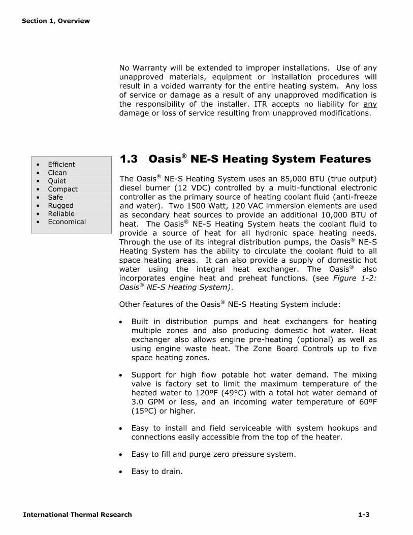
1.3 Oasis® NE-S Heating System Features
The Oasis® NE-S Heating System uses an 85,000 BTU (true output)diesel burner (12 VDC) controlled by a multi-functional electroniccontroller as the primary source of heating coolant fluid (anti-freezeand water). Two 1500 Watt, 120 VAC immersion elements are usedas secondary heat sources to provide an additional 10,000 BTU ofheat. The Oasis® NE-S Heating System heats the coolant fluid toprovide a source of heat for all hydronic space heating needs.Through the use of its integral distribution pumps, the Oasis® NE-SHeating System has the ability to circulate the coolant fluid to allspace heating areas. It can also provide a supply of domestic hotwater using the integral heat exchanger. The Oasis® alsoincorporates engine heat and preheat functions. (see Figure 1-2:Oasis® NE-S Heating System).
Other features of the Oasis® NE-S Heating System include:
Built in distribution pumps and heat exchangers for heatingmultiple zones and also producing domestic hot water. Heatexchanger also allows engine pre-heating (optional) as well asusing engine waste heat. The Zone Board Controls up to fivespace heating zones.
Support for high flow potable hot water demand. The mixingvalve is factory set to limit the maximum temperature of theheated water to 120ºF (49°C) with a total hot water demand of3.0 GPM or less, and an incoming water temperature of 60ºF(15ºC) or higher.
Easy to install and field serviceable with system hookups andconnections easily accessible from the top of the heater.
Easy to fill and purge zero pressure system.
Easy to drain.
• Efficient• Clean• Quiet• Compact• Safe• Rugged• Reliable• Economical

Section 1, Overview
1-4 The Oasis® NE-S Heating System
A high-temperature, stainless steel burner and stainless steeljacket.
14 US gallon, welded, insulated stainless steel coolant tank thatminimizes heat loss and optimizes heat recovery.
Domestic water flow switch for quick response to domestic hotwater demand.
Low coolant level switch.
Quiet operation and low power consumption.
Low pressure fuel system with built-in fuel pump.
Fuel efficient burner capable of burning a wide variety of diesel-based fuels (CSA/UL certified for diesel #1 and #2).
Exhaust has minimal smoke and smell.
Fan assisted sealed combustion chamber is designed to useoutside combustion air.
Low amperage draw ignition.
Electronically-controlled system featuring:
automatic Safety Shutdown; manual-resettable aquastats for safety overheat protection. LED indicators on the Control Panel for diagnostics. Patented, proprietary flame sensor.
Remote Operating Panel with ON/OFF switch for the dieselburner, AC elements, and engine pre-heat, if installed.
Control Panel with buttons for Power, Bypass, Reset, andindicator LED’s for operational and diagnostic information.

Section 1, Overview
International Thermal Research 1-5
Figure 1-2: Oasis® NE-S Heating System Overview
1.4 Critical Factors
THE INSTALLATION SHALL BE IN ACCORDANCE WITH THEREGULATIONS OF AUTHORITIES HAVING JURISDICTION
The key factors to keep in mind when planning and carrying out theinstallation are:
Mounting location restrictions for the Oasis® NE-S HeatingSystem and exhaust outlet (to reduce noise, vibration, heat loss,etc.).
Length, routing and sizing of fluid lines, air-flow tubing, exhaustpiping and wiring.
Unrestricted vent required to draw in 100% outside air forcombustion.
Ability for technician to easily access and service the product,especially fuel, plumbing, and electrical systems.
After installation, ability to purge water and fuel lines andinspect/test entire system using the ITR-supplied InspectionCheck Sheet.
Pay attention to thenotices of “Danger”“Warning” “Caution”and “Notice” in thismanual.

Section 1, Overview
1-6 The Oasis® NE-S Heating System
1.5 Equipment, Tools and Skills
As the user and/or installer, you must be qualified and authorized todo the installation, which requires mechanical aptitude and electricalknowledge. Make sure you comply with existing RVIA or ABYC (foryachts) industry practices, using the highest and most recentstandards and codes. Good workmanship is essential. Please referback to Section 1 – Overview, sub-Section 1.2, Protect YourWarranty.
You will need the following equipment and tools to install theheating system (not supplied). This list does not include optionalequipment and accessories:
Standard tools normally available in a well-equipped shop.
Approved fasteners for mounting the heater unit.
Steel (or stainless steel) 2” ID exhaust system piping, maximum12’ with no bends. (See Section 3 – Installing the ExhaustSystem, for details when bends are present.).
Exhaust collar.
ITR-muffler with straight-through design.
Two 2" air intake collars for connecting fresh outside air
Two 2" air intake hoses for connecting to fresh air intakes of theOasis NE-S.
1/4” supply fuel line, approved rubber or copper.
#10 sheet metal screws or wood screws to mount fan unitsinside the occupied areas.
Heater hose (to connect Oasis NE-S hose fittings to interiorfans).
Potable water hose/PEX to connect the Oasis NE-S potable waterhose/PEX fittings to the domestic water system.
Overflow tank to connect to the Oasis® Heating Module withclear plastic 5/8” hose; tank must be made of heavy-dutyplastic, vented with a screw-down cap, have an overflow outlet,and sturdy enough to mount firmly to a vertical surface.
Section 1, Overview
International Thermal Research 1-7
Up to five (5) thermostats (DC compatible) to allow temperatureregulation of the heating zones.
1.6 Testing and Inspection
After all components have been properly installed according tostandard practices, RVIA or ABYC (for yachts) standards, and therecommendations of this Installation and Operating Manual, theOasis® NE-S Heating System should be test-operated for inspectionpurposes.
For your convenience, you can use the pullout Inspection CheckSheet in this Manual. The Inspection Check Sheet is divided intoprogressive sections, allowing each phase of the inspection to becarried out systematically, and then signed off by authorizedpersons.

International Thermal Research 2-1
Mounting Oasis® NE-S HeatingSystem
2.1 Before You Begin
Plan the location of the Oasis® NE-S Heating System and all itsmajor components in advance to ensure the chosen locations arecompatible with installation requirements and within the technicalspecifications.
Consider the following factors to help you decide exactly wherebest to mount the Oasis® NE-S Heating System:
Oasis® NE-S Heating System weight when full (266 lbs).
Ventilation requirements.
Exhaust outlet location and maximum acceptable length,including all 90 degree bends. Refer to section 3.2.
Thru hull location and waterline (yachts). Refer to section3.2.
Potential for vibration and jarring.
Length of run from fuel source to heater. Refer to section4.2.
Most efficient plumbing runs.
Safe and convenient access for maintenance.
Number and location of interior fans.
Location of other equipment to be installed or connected tothe Oasis® NE-S Heating System, including the Zone ControlBox, heat exchangers, overflow tank, batteries, etc.
Section
2

Section 2, Mounting the Oasis® NE-S Heating System
2-2 The Oasis® NE-S Heating System
Make sure you are familiar with Section 1 – Overview of thisManual. If the system is not installed according to specificationsand with the correct equipment, your Oasis® NE-S Heating Systemmay not operate properly, safety may be compromised, and yourWarranty may be voided.
2.2 Identifying Your Oasis® NE-S HeatingSystem Model
As the owner, you must be fully aware of the controls andoperating features particular to your model of the Oasis® NE-SHeating System. This is essential for the proper functioning andlife of your Oasis® NE-S Heating System as well as protecting yourwarranty. Your model can be identified by locating the serialnumber label on the outside case of the Oasis® NE-S HeatingSystem. The serial number identifies the model type through thefirst series of letters and numbers.
2.3 Your Mounting Location
Your mounting location should consider the following:
Mounting location must be able to support double the grossweight of the Oasis® NE-S Heating System (i.e. 266 lbs. x 2 =532lbs. /120 KG x 2 = 240 KG) and must be of a non-combustible and non absorptive surface.
Oasis® NE-S Heating System is 15.25”H x 19.1”W x 36.1” D.(38.7 cm x 48.5 cm x 91.7 cm), see Figure 2-1: Oasis NE-SDimensions.
Oasis® NE-S Heating System must be installed in acompartment which is completely isolated from the atmosphereof living spaces.
Combustion air must be drawn from an outside source andcannot contain any combustible gases.
WARNING

Section 2, Mounting the Oasis® NE-S Heating System
International Thermal Research 2-3
Mount the unit with the front panel facing out and accessible.This mounting position simplifies installation and maintenance.Leave the left side of the unit accessible for maintenance.
The Oasis® NE Heating System must be mounted in an areathat provides unrestricted access to the front and left sidepanels. Allow space for connection to the fuel, coolant, andpotable water lines, as well as the power, exhaust, and airintake connections. The following are the minimum requiredclearances: 8” top clearance, 12" front clearance, 12" left sideclearance; 0” clearance to all other Oasis® NE Heating Systemsurfaces. Allow 1” clearance on the right side for attaching themounting brackets.
Oasis® NE-S Heating System must be mounted horizontal andlevel using eight, 1/4” through bolts and 1” diameter fenderwashers, lock washers and nuts.
Figure 2-1: Oasis® NE-S Dimensions
! DANGER

Section 2, Mounting the Oasis® NE-S Heating System
2-4 The Oasis® NE-S Heating System
Oasis® NE-S Heating System must not be installed or operated inany compartment with flammable gases.
If the Oasis® NE-S Heating System is going to be mounted in theengine compartment, check for adequate ventilation. When theengine is running this area could be under a negative pressure.Make sure the air-intake and exhaust hoses have no leaks and arewell fastened to the heater, muffler and thru-hull fitting. Assemblyparts that may cause injury through accidental contact should beprotected.
This is a direct vent system. The combustion air must be drawndirectly from the outside, without coming in contact with air thatcan infiltrate the living areas. See section 3.3.
It is recommended that a catchpan be placed under the Oasis®
NE-S Heating System to contain any unexpected leak.
Choose a sturdy surface in a location that won’t be undulyaffected by vibration and jarring from rough roads or roughseas.
Ensure that the exhaust tubing can be properly and safelyrouted to the outside. The maximum exhaust run for thesystem is 12’, including 90 degree bends. See section 3.2.
2.4 What NOT to Do
Don’t mount the Oasis® NE-S Heating System in the rear of thecoach or yacht underneath the sleeping area. The sound of theOasis® NE-S Heating System cycling on and off may disturblight sleepers.
2.5 Oasis® NE-S Mounting ProcedureAfter choosing the mounting location for the Oasis® NE-S HeatingSystem, mount the unit and ensure it is level. Secure the Oasis®
NE-S Heating System in place (against the wall, floor or amounting platform) using four (4) mounting brackets, eight (8) x
! WARNING
! DANGER

Section 2, Mounting the Oasis® NE-S Heating System
International Thermal Research 2-5
1/4” through bolts (or wood screws), and 1” diameter fenderwashers, lock washers, and nuts. (See Figure 2-2: Oasis NE-SMounting Brackets.).
Figure 2-2: Oasis® NE-S Mounting Brackets
2.6 Zone Control Board MountingProcedure
Mount the Zone Control Box (containing the Zone ControlBoard) vertically, close to the Oasis® NE-S. Allow sufficientroom to access the internal fuses as well as to view the displayLED’s on the front of the board.
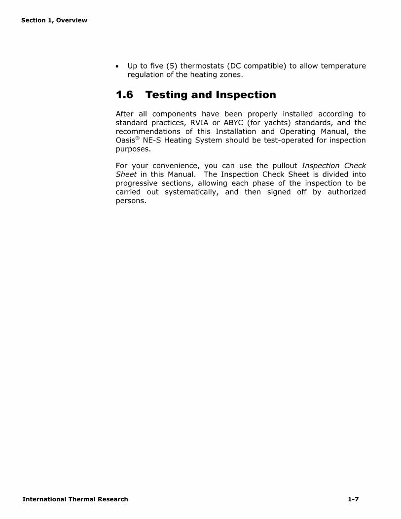
Mount the bracket against a wall using 2 flat head screws. Thedistribution module zone box will then click onto the bracket.See Figure 2-3.
Section 2, Mounting the Oasis® NE-S Heating System
2-6 The Oasis® NE-S Heating System
Figure 2-3: Zone Control Board
2.7 Remote Operating Panel MountingProcedure
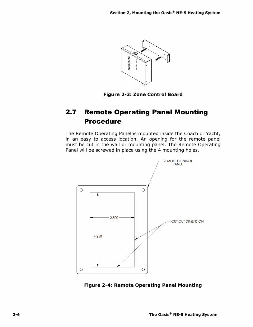
The Remote Operating Panel is mounted inside the Coach or Yacht,in an easy to access location. An opening for the remote panelmust be cut in the wall or mounting panel. The Remote OperatingPanel will be screwed in place using the 4 mounting holes.
Figure 2-4: Remote Operating Panel Mounting

International Thermal Research 3-1
Installing the Exhaust System
3.1 Before You Begin
For efficient and safe operation of the Oasis® NE-S Heating Systemfollow all recommendations for properly installing the exhaust. Anydeviations from these must be approved in advance by ITR.
Although the heater’s exhaust produces very low carbon monoxideemissions, caution is still advised:
Do not operate the Oasis® NE-S Heating System in anenclosed area unless there is adequate ventilation.
This is a direct vent system. The combustion air must bedrawn directly from the outside, without coming in contactwith air that can infiltrate the living areas. See section 3.3.
Never place any exhaust parts close to combustible material orthrough a combustible wall or ceiling without fireproof protection.The exhaust can reach high temperatures.
3.2 Mounting Location
If you can’t meet the technical specifications for mountingthe exhaust, don’t use the Oasis® NE-S Heating System. Theunit may perform poorly or become damaged if not installedaccording to specifications.
Recommended Exhaust Outlet Locations
The following is recommended for a coach exhaust outlet location:
Mount the exhaust outlet outside the coach, not inside theheater compartment. Otherwise, exhaust fumes couldinfiltrate the coach from the Oasis® NE-S Heating System.
Section
3
DANGER

Section 3, Installing the Exhaust System
3-2 The Oasis® NE-S Heating System
When mounting the Oasis® NE-S Heating System in a coach,the typical mounting location for the exhaust outlet is underthe floor of the heater compartment and out from the side ofthe coach, or out from the other side of the coach, directlyacross from the heater. The Oasis® NE-S Heating System willallow a maximum of 12' of exhaust piping, without any bends(excluding the exit bend from the heater).
Position the outlet of the exhaust pipe so that the exhaustexits out from under the side of the coach, not directlyunderneath the coach or under an opening window or vent.
If the exhaust is mounted under a slide-out, the outlet of theexhaust must be a minimum of 36" (inches) below the slide-out, including skirt and moldings.
In a yacht installation, the following is recommended for the exhaustoutlet location:
Mount the exhaust thru hull so that the exhaust fumes cannotenter or re-infiltrate any living areas.
Make sure that the thru hull is at least 30” above the waterline with a goose neck rise on the exhaust to help eliminatewater from entering the Oasis® NE-S through the exhaust. Ifthe dual exhaust air-intake thru hull is used, ensure that theair-intake is placed between 10 o’clock and 2 o’clock and alsogoose-necked to avoid water ingestion, see Figure 3-3: TheExhaust Goose Neck Configuration.
There needs to be a 1/8" air gap around the exhaust thru hull.The standard thru hull is 4" in diameter. The hole for thefitting should be 4-1/4". Make sure that the holes for themounting screws have enough material left to hold the screwsfirmly. The fitting must be centered in the hole.
Recommendation for Installation
The following applies to both a coach and yacht:
You may use sweeping bends, but each 90° bend isequivalent to two feet of exhaust piping. For example, if youuse two 90° bends, you must subtract 2' per bend from themaximum allowed 12' exhaust length. Therefore, you will berestricted to 8' of straight exhaust piping plus the two bends.Do not exceed these recommendations.

Section 3, Installing the Exhaust System
International Thermal Research 3-3
The combustion air must be drawn from outside the coach oryacht. The maximum length of each air-intake tubing is 7feet. Do not exceed this recommendation.
Use an ITR-manufactured muffler with a straight-throughdesign. No other muffler is acceptable.
Exhaust outlet is on the bottom of the Oasis® NE-S HeatingSystem, towards the back.
The exhaust and outlet are HOT and the surrounding areasmust be thermally shielded and protected from the hotsurfaces and heat build-up by insulation. Nothing can comeinto inadvertent contact with any part of the exhaust system.
Exhaust must have a minimum of 3” (7.6 cm) clearance fromall surfaces.
Ensure that the exhaust cannot be plugged or restricted.
The exhaust fitting on the Oasis® NE-S Heating System is2.0” O.D. and the exhaust pipe used must have a minimum of2.0” I.D. throughout its length.
All exhaust elbows must be of a large radius design.
The exhaust run must be supported a minimum of every 3’ ofits installed length.
The exhaust and Oasis® NE Heating System connection pointmust use appropriate clamps and sealing compound to ensurethat the connections are tight and leak free. Make sure anysealing used does not restrict the exhaust flow. The Oasis®
NE Heating System exhaust outlet pipe and the exhaust pipeitself must not be distorted or damaged during this process.
When the Oasis® NE-S Heating System is running theconnection points and the system must be checked for leaksand any found must be corrected. Periodically, check theexhaust fittings, connections, exhaust tube, and insulation forleaks and integrity; make repairs or replacements ifnecessary.
Appropriate exhaust insulation must be used to cover theentire length of any interior exhaust run.
! DANGER

Section 3, Installing the Exhaust System
3-4 The Oasis® NE-S Heating System
Solid stainless steel exhaust tubing or approved exhausttubing is recommended but an approved stainless steelflexible exhaust tubing can also be used. If flexible exhausttubing is used, the exhaust tubing must be inspectedregularly for leaks and deterioration as this type of exhaustdoes not have the life expectancy of solid tubing. U-boltclamps are recommended for joining flex and solid tubing asthey apply firm, even pressure.
In a coach, install an exhaust collar on the exhaust pipe toisolate the pipe from the coach frame. This reduces vibrationand noise and protects the coach from the effects of highexhaust temperature, see Figure 3-1: Installing the Exhaustsystem (Bottom Exhaust).
What NOT to Do
Don’t mount the exhaust pipe inside the heater compartment.
Don’t use more than 8’ of exhaust pipe if 180° of total bends arepresent, excluding the one bend at the outlet of the heater.
Don’t use any mufflers not supplied or approved by ITR.
Don’t use too much muffler cement or exhaust sealant that youblock the exhaust system.
Don’t over-tighten exhaust clamps or you may crush the Oasis®
NE-S Heating System’s exhaust outlet pipe.
3.3 Procedure
Figure 3-1: Installing the Exhaust System (Bottom Exhaust) showsa standard setup for the down exhaust.
To install the exhaust system:
1 Leave suitable air spacing to protect combustiblematerials; use an exhaust collar and metal shields whererequired.
2 Find an appropriate location for the exhaust hole of theheater. (See Figure 3-2)

Section 3, Installing the Exhaust System
International Thermal Research 3-5
3 Securely seal the exhaust piping to the Oasis® NE-SHeating System fitting using an approved exhaust clamp.
4 Connect the exhaust piping in series with the muffler,using heavy-duty exhaust clamps. If you use vibrationisolation mounts they must be high temperature.
5 Connect the flexible air-intake tubing (2” I.D.) to the air-intake fitting on top of the heater. Use a #32 gear clampto attach the tubing to this fitting.
The other end of the air-intake hose can be installed in 2configurations:
Installation of the air-intake adapters to theunderside of the RV
Locate a suitable location to mount the air-intakeadapters. Drill two, 2” holes through the floor. Insert theadapters from underneath and use 3 screws to secureeach one against floor. The air entrance of the air-intakeassembly shall be guarded or shielded to exclude rain,snow and debris. Use a #32 gear clamp to attach each air-intake tubing from the heater to each of the adapters.Ensure the run of tubing is as short as possible to facilitateair flow. See figure 3-1.
Installation of the air-intake adapter to the side ofthe RV
Locate a suitable location to mount the air-intakeadapters. Drill two, 2” holes through the side wall(minimum ¼”, maximum 2” wall thickness). Insert theadapters and use 3 screws to mount each one against sidewall. Use a #32 gear clamp to attach each air-intaketubing from the heater to each of the adapters. Ensure therun of tubing is as short as possible to facilitate air flow.See figure 3-1.
6 Secure both ends of each air-intake tubing with properlysized hose clamps to prevent air leaks.
7 Make sure the air-intake tubing and exhaust piping haveno leaks and are not touching each other.

Section 3, Installing the Exhaust System
3-6 The Oasis® NE-S Heating System
8 Protect the air-intake entrance from water and dirt with aguard or shield.
9 On a yacht, make sure the thru hull is at least 30” abovethe waterline and the exhaust must be goose-necked, seeFigure 3-3: The Exhaust Goose Neck Configuration.
This unit is not to be used with an air filter. The use of an airfilter can restrict the combustion air and result in improperand unsafe operation.
Figure 3-1: Installing the Exhaust System (Bottom Exhaust)
WARNING

Section 3, Installing the Exhaust System
International Thermal Research 3-7
Figure 3-2: The Exhaust Hole Location & Mounting Template
Figure 3-3: The Exhaust Goose Neck configuration

International Thermal Research 4-1
Installing the Fuel System
4.1 Before You Begin
For efficient and safe operation of the Oasis® NE-S Heating System,follow all recommendations for properly installing the fuel system.Any deviations from these must be approved in advance by ITR.
Use only diesel #1 and #2 in the Oasis® NE-S Heating System. DONOT USE GASOLINE, CRANKCASE OIL, OR ANY OIL CONTAININGGASOLINE.
Keep fuel lines away from any heat source above 100°F (38°C).
Keep gasoline and any equipment that uses gasoline away from theOasis® NE-S Heating System location. The Oasis® NE-S HeatingSystem is not rated for use in an explosive environment.
Never share the fuel supply to the Oasis® NE-S Heating Systemwith any other fuel-burning device.
4.2 Fuel System Installation
The fuel pump in the Oasis® NE-S Heating System has a maximumflow capacity of 32 GAL/Hr and a maximum pressure of 11.5 psi. A10 micron fuel filter is recommended. Select a fuel filter based onthese requirements.
Recommendations for Installation
The Oasis® NE-S Heating System’s fuel connections are accessedfrom the top of the heater. The fuel inlet/outlet connections arelocated on the top right of the Oasis® NE-S Heating System andconsist of 1/8” NPT threaded female fittings. The minimumrecommended size for the fuel line is ¼” I.D. The fuel return lineshould return directly to the fuel supply tank.
Section
4
! DANGER
! WARNING

Section 4, Installing the Fuel System
4-2 The Oasis® NE-S Heating System
The following is recommended for the fuel system installation:
The fuel supply from the fuel storage tank to the fuel inlet must befrom a dedicated fuel pickup on the top of the tank.
The fuel supply line should be installed with minimal rise fromthe fuel tank. The total rise from the bottom of the pickuptube to the fuel inlet on the Oasis® NE-S should not exceed60”. There are no minimum clearance requirements betweenthe fuel tank and the Oasis® NE-S.
The fuel line must be routed and secured to prevent damage,chafing and kinking during normal operation.
All fuel line connection points and hoses must use suitableclamps and/or sealant and must be checked for leaks on theinitial installation and also periodically as part of normalmaintenance.
A primary, UL and/or CSA approved fuel oil filter (notprovided) must be installed inline on the fuel supply hose,between the tank and the Oasis® NE-S, in a manner thatensures easy access for maintenance. A secondary fuel filteris mounted inside the Oasis® NE-S, just behind the fuelnozzle. Both filters must be inspected and replaced asrequired as part of normal maintenance.
Fuel line hose used must be appropriate for yourrequirements. It is strongly recommended that the hoseshave permanently installed end fittings.
4.3 What NOT to Do
Don’t allow the fuel or the fuel lines to become contaminatedwith foreign material.
Don’t allow the fuel lines to become damaged or constricted.
Ensure that fuel lines are always protected from contamination byforeign material. When installing or servicing, seal off ends toprevent contamination. After installing, you may also wish to flushthe fuel line to rid of it air and any foreign material.
NOTICE
! CAUTION
! CAUTION
Section 4, Installing the Fuel System
International Thermal Research 4-3
4.4 Procedure
To complete the fuel system installation:
1 Install an inline fuel filter. The optimal location is on acompartment wall next to the Oasis® NE-S, inline betweenthe fuel tank and the Oasis® NE-S.
2 Connect the fuel line to the dedicated fitting on the maindiesel fuel tank.
3 Inspect the supply fuel line for any loose connections ordamage. Fittings must be airtight.
4 If desired, install a shut-off valve on the tank side of thefuel filter to allow shutdown and filter service.
International Thermal Research 5-1
Installing Fan Heaters
5.1 Before You Begin
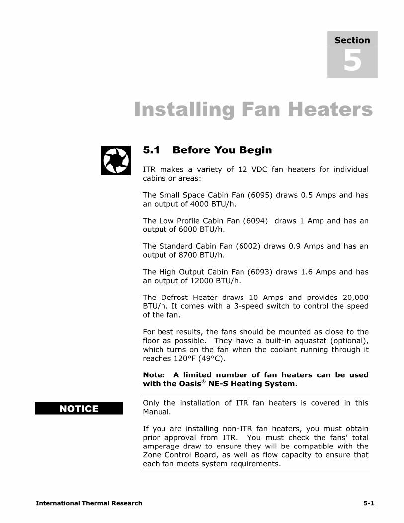
ITR makes a variety of 12 VDC fan heaters for individualcabins or areas:
The Small Space Cabin Fan (6095) draws 0.5 Amps and hasan output of 4000 BTU/h.
The Low Profile Cabin Fan (6094) draws 1 Amp and has anoutput of 6000 BTU/h.
The Standard Cabin Fan (6002) draws 0.9 Amps and has anoutput of 8700 BTU/h.
The High Output Cabin Fan (6093) draws 1.6 Amps and hasan output of 12000 BTU/h.
The Defrost Heater draws 10 Amps and provides 20,000BTU/h. It comes with a 3-speed switch to control the speedof the fan.
For best results, the fans should be mounted as close to thefloor as possible. They have a built-in aquastat (optional),which turns on the fan when the coolant running through itreaches 120°F (49°C).
Note: A limited number of fan heaters can be usedwith the Oasis® NE-S Heating System.
Only the installation of ITR fan heaters is covered in thisManual.
If you are installing non-ITR fan heaters, you must obtainprior approval from ITR. You must check the fans’ totalamperage draw to ensure they will be compatible with theZone Control Board, as well as flow capacity to ensure thateach fan meets system requirements.
Section
5
NOTICE

Section 5, Installing Fan Heaters
5-2 The Oasis® NE-S Heating System
5.2 Fan System Operation
ITR fans consist of a 12 VDC brushless fan and heater coilsimilar to a radiator.
When the heater unit comes on, the fan draws ambient airfrom the interior, blows it through the heater coil and backinto the interior through a vent. There must be an input andoutput vent for each fan unit.
Features
The Zone Control Board will not run the fans unlessthe coolant inside the Oasis® NE-S tank is above 120F.However, during the initial startup, the coolant in thelines will be lower than 120F until it has had a chanceto mix with the coolant in the tank. ITR heater fanscan be supplied with a built-in aquastat, whichprevents fan operation until the system has reachedminimum operating temperature. Figure 5-1 showshow to wire up the aquastat in a fan.
Figure 5-1: Wiring the Fan’s Aquastat
If a “passive” radiant heat system is desired (i.e.baseboard or fin and tube configurations), consult ITRfor recommended installation procedures and design.
Section 5, Installing Fan Heaters
International Thermal Research 5-3
Multiple Zone Heating
The Oasis® NE-S Heating System can supply heat up to fiveinterior zones.
Up to five thermostats (positive DC compatible) can beinstalled to allow temperature regulation of the zones. Thethermostat controls the fan heater.
For larger installations, consult ITR.
Accessories and Components Needed
In addition to the fans themselves, you will need at leastsome of the following optional accessories and equipmentwhich are not supplied but which can be purchasedseparately.
Thermostats — thermostats can be installed in theinterior. Digital or analog versions are available.
Air Outlet Vents — covers that are installed flushwith the wall to vent heat for the installed heater unit.
Fan Guards — to protect the fan blades fromdamage, recommended for fans installed in storageareas or other accessible areas where something couldcontact the fan blades.
Screws — #10 sheet metal screws or wood screws tomount the fan units. See Figure 5-2: Mounting aSpacesaver Fan.
Two-Speed Fan Switches – to enable low and high-speed settings from inside the coach or yacht; for usewith the ITR Cabin heater and Spacesaver fan.
Three-Speed Fan Switches — to enable low,medium and high-speed settings from inside the coachor yacht; for use with the ITR defrost heater.
Air Ducting — to allow you to install fans in a remotelocation (i.e. not directly adjacent to the interior spaceto be heated) and duct the heated air to its outputlocation. Also, air outlet plates to allow you toinstall ducting for one, two or three separate outlets(e.g. you can use one fan to heat two different areasby installing a dual air outlet plate).

Section 5, Installing Fan Heaters
5-4 The Oasis® NE-S Heating System
5.3 What NOT to Do Don’t install more fans that require more heat than
the Oasis® NE-S can produce. Your system will notrun effectively. If you choose to use fans that drawhigher current (more than 10 amps on zone 1, ormore than 5 amps on zones 2-5), install a relay tohandle the extra load; see Figure 5-3: Installing aRelay for Additional Fan Amperage. See section 6.4 forinformation on the Zone Control Board.
Don’t mount the return air outlet too close to thefan’s air intake source.
5.4 Mounting Locations
Carefully choose the mounting locations of your fans:
Locate the fans to evenly heat the specific zone.
Provision must be made to protect potable water linesfrom freezing.
Install fan at floor level or very near floor level, in orderto optimize circulation.
Allow a minimum 16 square inch (100 cm sq.) opening inthe fan heaters’ mounting compartment to allow sufficientintake of air.
ITR’s Cabin Fans (Low Profile Cabin Fan pictured at left) areattached to a mounting plate. They are designed to mounthorizontally on a flat surface.
The thermostat should not be mounted on walls outside ofthe zone because that could cause false temperaturereadings. Mount on interior walls and bulkheads, away fromwindows, heater vents and cabin fan heaters.
ITR can suggestoptimal fan locationsif you provide a floorplan of your coachor yacht.

Section 5, Installing Fan Heaters
International Thermal Research 5-5
5.5 Procedure
After choosing the appropriate mounting location andconfiguration:
1 Mount the fan using #10 sheet metal screws or woodscrews, see Figure 5-2: Mounting a Low Profile Cabin Fan.
2 If you are using ducting and a dual air outlet plate for anyfan, limit the total length of duct for both outlets to 36” foroptimum air output.
3 Select the appropriate mounting location for thethermostat, as well as any fan speed switches. You willwire these up to the Zone Control Board in Section 6 –Wiring The Electrical System.
4 The Zone Control Board can control up to 5 zones. Thecabin fan 1 lead (orange) can supply up to a maximum of10 Amps. The other cabin fan leads 2-5 can supply up to amaximum of 5 Amps each. The total current draw is not toexceed 18 Amps for all cabin fan leads.
5 If the system requires higher amperage draws, install aseparate relay to power the fans. This relay will use theexisting fan circuit as a signal and must be wired to asecondary power source (not the heater’s control board).See Figure 5-3: Installing a Relay for Additional FanAmperage.
6 To install plumbing lines to the fans, see Section 7 –Plumbing the System.

Section 5, Installing Fan Heaters
5-6 The Oasis® NE-S Heating System
Figure 5-2: Mounting a Low Profile Cabin Fan
Figure 5-3: Installing a Relay for Additional Fan Amperage

International Thermal Research 6-1
Wiring the Electrical System
6.1 Before You Begin
The Oasis® NE-S and its electrical Control Board (mountedinternally) are pre-wired and have been thoroughly tested togetheras a unit. To integrate the Oasis® NE-S into your system, wiring willbe required between the following system components:
120VAC Power
12VDC battery
Oasis® NE-S Heater
Oasis NE-S Remote Operating Panel
Oasis NE-S Zone Control Board
Thermostats
Cabin Fans
To review the wiring for the Oasis® NE-S Heating System, refer tothe wiring diagram shown in Figure 6-1: System Wiring.
All electrical connections and wiring must comply with normally-accepted 12 VDC and 120 VAC wiring practices, local regulations,and ABYC/RVIA standards. Only a qualified electrical installershould complete the wiring. All field wiring is to be in accordancewith CSA Standard C22.1, Canadian Electrical Code Part l or theNational Electrical Code, ANSI/NFPA 70.
The main electronic Control Board is mounted onboard the Oasis®
NE-S itself. It has no user adjustable components.
Section
6
WARNING
NOTICE

Section 6, Wiring the Electrical System
6-2 The Oasis® NE-S Heating System
Figure 6-1: System Wiring
6.2 Oasis® NE-S 12 VDC
The following apply to the 12 VDC connections of the Oasis® NE-S:
There is one paired set of 12 VDC electrical connections on thetop left of the Oasis® NE-S. They consist of the primary DCpositive (red) and negative (black) connection and are 12 gaugestranded copper wires.

Section 6, Wiring the Electrical System
International Thermal Research 6-3
Primary DC power should originate from a dedicated connection onthe house battery bank. A 30 amp fuse must be included close toand inline from the battery to the positive (red) connection on theOasis® NE-S Heating System. The primary power wire gauge mustbe sized to permit no more than a 3% voltage drop from thebattery to the Oasis® NE-S Heating System.
The 12 VDC connections to the Oasis® NE-S must be connecteddirectly to the battery (through a fuse). There should be nobattery disconnect switch between the battery and the Oasis®
NE-S. This is to prevent the burner from being shut downwithout first going through its appropriate purge period. Withouta proper purge period to cool the combustion chamber, theinternal components of the Oasis® NE-S will become damaged.Note that the power to the Zone Control Board (see section 6.5)can go through a battery disconnect switch.
A properly-shielded power system is required for safe, trouble-free operation.
6.3 Oasis® NE-S 120 VAC
The Oasis® NE-S Heating System is equipped with two 1500watt, 120 VAC (60 Hz) immersion elements. The connectionsfor the electrical supply are on the top left side of the Oasis®
NE-S Heating System, under a cover, labeled AC power.
The power wires for the AC immersion elements are 14 gaugestranded copper leads that use standard AC color code (black-hot, white–neutral, green-ground). These are to be connectedusing standard 120 VAC electrical connectors and terminals.
There are two sets of AC power wires, one set with black heatshrink (primary) and one set without heat shrink (secondary).Each individual set must be connected to a separate AC circuitbreaker. The primary set of wires is connected to the left ACelement, and the secondary set of wires is connected to theright AC element, located inside the Oasis® NE-S HeatingSystem. If only one AC circuit breaker is available, you mustconnect to the primary wire set only. Once the connections arecompleted, the wires are to be inserted back into theircompartment and the cover secured.
The ground wire (green) is shared between the two connections.
WARNING

Section 6, Wiring the Electrical System
6-4 The Oasis® NE-S Heating System
6.4 Wiring the Zone Control Board
Primary 12 VDC power to the Zone Control Board shouldoriginate after the master disconnect switch from a dedicatedconnection on the house battery bank.
A 25 amp fuse or breaker must be included inline from thepower source to the positive connection on the Zone ControlBoard. The primary power wire gauge must be sized topermit no more than a 3% voltage drop from the powersupply to the Zone Control Board.
The Oasis® NE-S and the Remote Operating Panel areconnected to the Zone Control Board through the electricalconnections located at the bottom of the Zone Control Board.
The Zone Control Board connects to the thermostats andcabin fans through a 14 pin plug, with butt connect leads.
Cabin Fan Leads
The positive (red) lead from each cabin fan is to be attachedto one of the trailing cabin fan leads, color coded for zones,from the thermostat and cabin fan connector plug.
The negative lead from each cabin fan is to be attached to aground terminal (not provided) that is connected to a batteryground.
The cabin fan 1 leads (orange) can supply up to a maximumof 10 Amps. The other cabin fan leads 2-5 can supply up to amaximum of 5 Amps each. The total current draw is not toexceed 18 Amps for all cabin fan leads.
If the system requires higher amperage draws, install aseparate relay to power the fans. This relay will use theexisting fan circuit as a signal and must be wired to asecondary power source (not the heater’s control board). SeeFigure 5-3.

Section 6, Wiring the Electrical System
International Thermal Research 6-5
Thermostat Leads
The power lead to the thermostat should be fused (1 Amp)and attached to a power terminal (not provided) that isconnected to the battery.
The return lead from each thermostat is to be attached toone of the trailing thermostat leads, color coded for zones,from the thermostat and cabin fan 14 pin connector plug onthe zone control board.
Note that the zone control board uses Heating Loop 1 tosupply coolant to Zones 1 and 2, and uses Heating Loop 2 tosupply coolant to Zones 3, 4, and 5. Zones 1 and 2 arecalling for heat, the zone control board will activate the HeatLoop 1 pump. When Zones 3, 4, and 5 are calling for heat,the zone control board will activate the Heat Loop 2 pump.
6.5 What NOT to Do
Never shut off the Oasis® NE-S Heating System power via an inlinebattery or master switch while the system is running. Neverdisconnect the battery when the Oasis® NE-S Heating System isrunning, and never disconnect the battery while the inverter ischarging. Do not wire the Oasis® NE-S Heating System through adisconnect that is used as a normal shut-down of the DC system.
Doing either will severely damage the Oasis® NE-S Heating Systembecause it fails to automatically purge the combustion chamber.Such damage is detectable upon inspection and will not be coveredunder warranty. Always shut the system off using the normalsystem controls, after it has completed its purge and cooled downthe combustion chamber.
NOTICE
International Thermal Research 7-1
Plumbing the System
7.1 Before You Begin
For efficient and safe operation of the Oasis® NE-S Heating System,follow all of the recommendations in this section for properlyinstalling the plumbing system. Any deviations from these must beapproved in advance by ITR.
The Oasis® NE-S Heating System must use a non-toxic, propyleneglycol based coolant with additives generally recognized as safe”GRAS” by the FDA. Use of non-propylene glycol based coolant canbe harmful if contamination of potable water occurs due to a leak inthe heat exchanger, which could be caused if the fresh water in thesystem is allowed to freeze.
For an efficient Oasis® NE-S Heating System operation, you must:
Minimize heat loss from the Oasis® NE-S and hoses.
Balance the heat output for each of the zones and balance theheat drawn by both space heating loops. Balancing can be doneby adjusting the number and size of the cabin fans installed ineach loop in the Oasis® NE-S Heating System. Figure 7-2:Plumbing Oasis® NE-S Heating System for Five Zones, shows atypical plumbing layout for circulating coolant from the Oasis®
NE-S to the cabin fans in the two loops, and back to the Oasis®
NE-S.
Section
7
DANGER
When heat is calledfor, the distributionpumps in the NE-Ssend heated fluid outto the cabin fans andpotable water heatexchanger.

Section 7, Plumbing the System
7-2 The Oasis® NE-S Heating System
7.2 Coolant Plumbing Installation
The plumbing installation should consider the following:
The Oasis® NE-S has an overflow fitting located on the top of theunit. Ensure a four (4) quart minimum overflow bottle isattached to the overflow fitting. The connection point should befrom the bottom of the overflow bottle.
The supply and return coolant plumbing connections are on thetop of the Oasis® NE-S Heating System. The supply fittings are1/2" NPT (female) bulkhead fittings, and the return fittings are1/2" NPT (male) fittings. The supply coolant outputs from theOasis® NE-S are labeled "Heating Loop 1 Supply" and "HeatingLoop 2 Supply". The return coolant inputs to the Oasis® NE-Sare connections labeled "Heating Loop 1 Return" and "HeatingLoop 2 Return". Ensure proper direction of flow. Refer to Figure7-1: Oasis® NE-S Overview for the location of the fittings.
Two 1/2" NPT to 3/4" hose barb fittings must be fitted into theOasis® NE-S coolant supply connections. Two 1/2" FPT to 3/4"hose barb fittings must be fitted into the Oasis® NE-S coolantreturn connections. All connections must be tightened to a leakfree condition using an appropriate thread sealant.
Hose and/or tubing used to connect to the Oasis® NE-S supplyand return connections must be heavy duty heater hose,minimum 3/4” I.D, or 5/8” PEX.
All fittings (except Heat Loop 1 & 2 return fittings) on the Oasis® NErequire two wrenches when tightening. One wrench must be placedon the bulkhead fitting and held in place to prevent this fitting frombeing overstressed. The other wrench can be used to tighten thematching half of the fitting onto it. Failure to follow this procedurewill damage the Oasis® NE-S and the fittings.
Do not operate the Oasis® NE-S Heating System until a properwater/anti-freeze solution has been added to the Oasis® NE-S andthe heating system and all trapped air has been bled. An inadequatemixture may cause system circulation problems and potentialOasis® NE-S Heating System damage and/or personal injury. Useonly a non-toxic, propylene glycol based coolant with additivesrecognized as safe “GRAS” by the FDA. Refer to the anti-freezemanufacturer recommendations for instructions for your application.
NOTICE
! DANGER

Section 7, Plumbing the System
International Thermal Research 7-3
Figure 7-1 Oasis® NE-S Heating System Overview
Figure 7-2: Plumbing Oasis® NE-S for 5 Zones

Section 7, Plumbing the System
7-4 The Oasis® NE-S Heating System
All plumbing lines must be routed and secured to preventdamage, chafing and kinking.
Ensure that the coolant flow is adequate through the Oasis® NE-S Heating System. The flow rate through each of the spaceheating loops should be at least 2.5 GPM. An indication ofinadequate flow is a large temperature difference between thefirst cabin fan and the last cabin fan in each space heating loop(when the Oasis® NE-S Heating System is running and up tonormal operating temperature). In a properly flowing system,each fan in the space heating loop will have an outlettemperature that is only a few degrees cooler than the precedingfan.
The Oasis® NE-S should be filled and flushed prior to operationto remove any foreign debris.
Use heavy-duty heater hose or PEX tubing. Slip-on foaminsulation coverings may be used over the hose fittings to reduceheat loss. Secure all hose connections with constant tensionspring clamps.
7.3 What NOT to Do
The Oasis® NE-S Heating System’s coolant distribution pumps areone of the most critical parts of the system. Never let the pumpsrun dry or damage will occur to the impellers. This is not coveredunder warranty.
Don’t use low-quality heater hose.
Don’t let the hose come into contact with solvents, which maycause it to soften and swell. If there is any risk that solvents maycontact the hose, insert it into PVC plastic tubing for protection.
NOTICE

Section 7, Plumbing the System
International Thermal Research 7-5
7.4 Coolant Plumbing InstallationProcedure
To install and connect the Oasis® NE-S and heater hose:
1 Connect two 1/2" NPT to 3/4" hose barb fittings onto theOasis® NE-S coolant supply connections. Connect two 1/2" FPTto 3/4" hose barb fittings onto the Oasis® NE-S coolant returnconnections. Tighten all connections to a leak free conditionusing an appropriate thread sealant.
2 Hose and/or tubing used to connect to the Oasis® NE-S supplyand return connections must be heavy duty heater hose,minimum 3/4” I.D, or 5/8” PEX.
Install the cabin fans for both space heating loops byconnecting the supply line to the lower port on the cabin fanand the outlet to the next fan in the series loop. Each cabinfan heater should be plumbed so that fluid supply enters thebottom of the heating core and exits from the top. This helpskeep air from being trapped in the cabin fan core. Ensureproper direction of flow. Refer to Figure 7-1: Oasis® NE-SOverview for the location of the fittings. Ensure there are nokinks or sharp bends that might restrict the fluid flow. SeeFigure 7-3: Three Approved Methods of Installing Heater Hose(Consult ITR for Alternative Methods and Products) formethods of attaching the heater hose.
3 Once the two space heating loops have been set up with thecabin fans, connect the two individual space heating loopsupply lines to the "Heating Loop 1 Supply" and "Heating Loop2 Supply" connections on the Oasis® NE-S. Connect the twospace heating return lines to the "Heating Loop 1 Return" and"Heating Loop 2 Return" connections. Note that the zone controlboard uses Heating Loop 1 to supply coolant to Zones 1 and 2,and uses Heating Loop 2 to supply coolant to Zones 3, 4, and 5.
4 The Oasis® NE-S has an overflow fitting located on the top ofthe unit. Ensure a four (4) quart minimum overflow bottle isattached to the overflow fitting. The connection point should befrom the bottom of the overflow bottle.
Section 7, Plumbing the System
7-6 The Oasis® NE-S Heating System
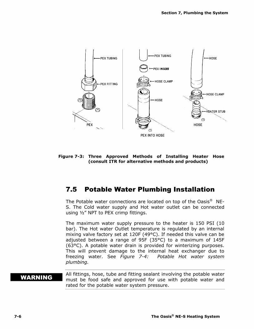
Figure 7-3: Three Approved Methods of Installing Heater Hose(consult ITR for alternative methods and products)
7.5 Potable Water Plumbing Installation
The Potable water connections are located on top of the Oasis® NE-S. The Cold water supply and Hot water outlet can be connectedusing ½” NPT to PEX crimp fittings.
The maximum water supply pressure to the heater is 150 PSI (10bar). The Hot water Outlet temperature is regulated by an internalmixing valve factory set at 120F (49°C). If needed this valve can beadjusted between a range of 95F (35°C) to a maximum of 145F(63°C). A potable water drain is provided for winterizing purposes.This will prevent damage to the internal heat exchanger due tofreezing water. See Figure 7-4: Potable Hot water systemplumbing.
All fittings, hose, tube and fitting sealant involving the potable watermust be food safe and approved for use with potable water andrated for the potable water system pressure.
WARNING

Section 7, Plumbing the System
International Thermal Research 7-7
Figure 7-4 Potable Hot Water System Plumbing
7.6 Engine Plumbing Installation
The Engine Heat Inlet/Outlet connections are located on top left(towards the back) of Oasis® NE-S. These connection points are1/2" hose. The connection can be made by placing PEX inserts intothe 1/2" PEX hose, and sliding 1/2" PEX into the hose and clampingit in place. Alternatively, a 1/2" barb to 1/2" or 3/4" barb fitting canbe used to make the connection to the engine coolant hose.
Hot coolant from the engine enters the Oasis® NE-S at the “EngineHeat Inlet”. The “Engine Heat Outlet” returns the coolant back tothe engine supply. This makes use of engine waste heat.
If the pre-heat function is installed, an additional pump is installed(inside the Oasis® NE-S) to move the engine coolant through theengine heat exchanger, when the engine is turned OFF. The pre-heat switch on the Remote Operating Panel will activate this pump.See Figure 7-5: Engine heat/pre-heat system plumbing.
It is recommended to contact the vehicle/engine manufacturer priorto proceeding with the engine plumbing installation.
Prior to operating the engine pre-heat pump, the engine coolantloop must be connected to the Oasis® NE-S and the coolant linepurged of air. The power to the engine pre-heat pump is leftdisconnected at the factory. Once the engine coolant loop has beenpurged, the side cover of the Oasis® NE-S must be removed and thepower to the engine pre-heat pump must be connected.
WARNING

Section 7, Plumbing the System
7-8 The Oasis® NE-S Heating System
Figure 7-5 Engine Heat / Pre-heat System Plumbing
7.7 Procedure For Filling/Purging TheOasis® NE-S Heating System
1 Do not operate the Oasis® NE-S Heating System until theproper water/anti-freeze solution has been added to the Oasis®
NE-S Heating System and all trapped air has been bled. Aninadequate mixture may cause system circulation problems andpotential Oasis® NE-S Heating System damage and/or personalinjury.
Use only a non-toxic, propylene glycol based coolant withadditives recognized as safe “GRAS” by the FDA. Refer to theanti-freeze manufacturer recommendations for instructions foryour application.
2 Remove the front cover of the Oasis® NE-S, and using a selfpriming pump, fill the Oasis® NE-S Heating System through thefiller port (1/2" hose barb connection) located at the bottom ofthe unit with a 50/50 mixture of propylene glycol and water.

Section 7, Plumbing the System
International Thermal Research 7-9
3 When the fluid starts to run into the overflow bottle, turn on theBypass Switch on the Zone Control Board and wait until thecoolant lines are filled and the overflow bottle fills to the"Minimum when cool" level.
4 When this level is reached, turn OFF the filler pump, and keepthe bypass switch turned ON until the system is purged of airand the coolant level in the overflow bottle does not change.
5 Once the system has been purged of air, turn OFF the BypassSwitch on the Zone Control Board. This Bypass Switch shouldremain off during normal operation. It is only used to fill andpurge the system. The shut-off valve on the filler hose must bein the closed position when the system has been filled.
Figure 7-6 Filling/Purging Oasis® NE-S Heating SystemEngine Heat / Pre-heat System Plumbing.

International Thermal Research 8-1
Operating the Oasis® NE-SHeating System
This section describes the features, operation and maintenanceof your new Oasis® NE-S Heating System. READ THESEINSTRUCTIONS AND SAVE FOR REFERENCE.
8.1 Features of Your Oasis® NE-SHeating System
The Oasis® NE-S Heating System uses an 85,000 BTU (trueoutput) diesel burner controlled by a 12 VDC multi-functionalelectronic controller as the primary source of heating coolant(anti-freeze and water). Two 1500 Watt, 120 VAC immersionelements are used as secondary heat sources to provide anadditional 10,000 BTU of heat. The Oasis® NE-S Heating Systemheats the coolant to provide a source of heat for all hydronicspace heating needs. Through the use of its integral distributionpumps, the Oasis® NE-S Heating System has the ability tocirculate the coolant to all space heating areas. It can alsoprovide a supply of domestic hot water using the integral heatexchanger. The Oasis® also incorporates engine heat and preheatfunctions. (See Figure 1-2: Oasis® NE-S Heating System).
Other features of the Heating System include:
Built in coolant distribution pumps capable of supplyingcoolant to multiple heating fans in two separate loops, locatedin up to five different zones.
An internal heat exchanger provides for production of potablehot water.
A separate internal heat exchanger provides for use of enginewaste heat and engine pre-heat (optional). For engine pre-
Section
8

Section 8, Operating the Oasis® NE-S Heating System
8-2 The Oasis® NE-S Heating System
heat, an optional engine pre-heat pump and specific remotepanel switch must be installed.
Support for high flow domestic hot water demand. Thesystem increases ground water temperature by 60F at a flowof 3.0 GPM (using only the diesel burner). The mixing valve(factory pre-set), will limit the temperature to 120F.
Easy to install and field serviceable with the Oasis® NE-SHeating System hookups and connections easily accessiblefrom the top of the heater.
Easy to fill and purge, zero pressure system.
Easy to drain.
A high-temperature, stainless steel burner and stainless steeljacket.
13.75 US gallon welded, insulated stainless steel coolant tankthat minimizes heat loss and optimizes heat recovery.
Domestic water flow switch for quick response to domestichot water demand.
Low coolant level switch on the tank.
Quiet operation and low power consumption.
Low pressure fuel system with built-in fuel pump.
Fuel efficient burner capable of burning a wide variety ofdiesel-based fuels (CSA/UL certified for diesel #1 and #2).
Exhaust has minimal smoke and smell.
Fan assisted, sealed combustion chamber is designed to useoutside combustion air.
Simple, low amperage draw ignition.
Electronically-controlled system with:
automatic Safety Shutdown; manual-resettable aquastats for safety overheat
protection. LED indicators on the Control Panel for diagnostics. Patented, proprietary flame sensor.

Section 8, Operating the Oasis® NE-S Heating System
International Thermal Research 8-3
Remote Operating Panel with ON/OFF switch for the dieselburner, AC elements, and engine pre-heat, if installed.
Control Panel buttons for Power, Bypass, Reset, and indicatorLED’s for operational and diagnostic information.
8.2 Operating Instructions for theOasis® NE-S Heating System
The Oasis® NE-S Heating System must be installed andconnections made in accordance with the recommendations inthis Installation and Operating Manual prior to operating theheater.
The Oasis® NE-S Heating System, Figure 8-1: Oasis® NE-SHeating System, heats the coolant to a preset temperatureand will automatically cycle to maintain the temperature.
Figure 8-1 Oasis® NE-S Heating System Overview
NOTICE

Section 8, Operating the Oasis® NE-S Heating System
8-4 The Oasis® NE-S Heating System
8.3 Turning the Power to the Oasis® NE-S Heating System ON
The Oasis® NE-S Heating System’s main Control Panel (Figure8-2), located on the front of the heater, contains three pushbuttons: ON/OFF power, Bypass, and Reset. The powerswitch must be pushed ON (power LED will turn ON) to turnthe DC electrical power to the main control board ON and isrequired to be left ON whenever heat is required.
The Zone Control board (Figure 8-4) will be poweredwhenever the master disconnect switch is ON. The masterdisconnect switch must be left ON whenever heat is required.
When the Oasis® NE-S Heating System is shut down for anyextended period or the season, it is recommended that thepower switch and the battery master disconnect switch beturned OFF.
Figure 8-2 Oasis® NE-S Main Control Panel

Section 8, Operating the Oasis® NE-S Heating System
International Thermal Research 8-5
Do not operate the Oasis® NE-S Heating System until a suitablewater/anti-freeze solution is in the heater and all trapped air hasbeen bled or removed.
Use only a non-toxic propylene glycol based coolant withadditives generally recognized as safe ”GRAS” by the FDA in theOasis® NE-S Heating System.
8.4 Activating the Burner (Primary) andAC Heat (Supplemental) from theRemote Operating Panel
Activating the Burner (Primary Heat Source)
The burner switch on the Remote Operating Panel controls theON/OFF of the diesel burner (primary heat source). When theburner switch is turned ON, the diesel portion of the Oasis®
NE-S will turn ON after ten seconds. The Burner LED will turnON when the diesel burner has been activated. The burnerwill continue to operate until the coolant in the Oasis® NE-Sreaches cycling temperature. At this point, the diesel burnerwill turn OFF. If the Oasis® NE-S Heating System coolantshould cool down below this temperature range, the burnerwill again commence firing and will continue until either theburner switch on the remote panel is turned OFF or cyclingtemperature is again achieved. If the burner switch on theremote panel is turned OFF, or cycling temperature isachieved, the burner stops and the Oasis® NE-S enters a twominute cool down stage prior to completely shutting down.
Activating the AC Immersion Element(s) (SupplementalHeat Source)
Place the AC power switch on the Remote Operating Panel toeither the one element or two element position. The AC Heat(green) LED will turn ON indicating the AC element(s) areenergized and the coolant is being electrically heated. Theelements will continue to operate until the coolant in theOasis® NE-S reaches cycling temperature. At this point, theelements and the AC heat LED will turn OFF. If the Oasis®
NE-S Heating System coolant should cool down below thistemperature range, the AC element(s) will again be energizedand will continue until either the AC switch on the remotepanel is placed in the OFF position or cycling temperature is
NOTICE
! DANGER

Section 8, Operating the Oasis® NE-S Heating System
8-6 The Oasis® NE-S Heating System
again achieved. If the AC element switch on the remotepanel is turned OFF, or cycling temperature is achieved, theAC elements are de-energized and the AC Heat (green) LEDturns OFF.
Activating the Burner and AC immersion Element(s)Jointly
Turn the burner switch ON and place the AC power switch onthe Remote Operating Panel to either the one element or twoelement position. The Burner and AC Heat (green) LED’s willturn ON indicating the diesel burner and AC element(s) havebeen selected.
8.5 Activating the Cabin Fan Heatersthrough the Thermostats
Burner or AC Heat or Engine Heat Source Available
Any thermostat connected to the Zone Control Board andcalling for heat will cause the cabin fan and loop pumpcontrolled by that thermostat to be enabled (only if thecoolant inside the Oasis® NE-S is above 120F). Note thatzones 1 and 2 control Loop 1 Pump. Zones 3, 4, and 5 controlLoop 2 Pump. Once the room temperature has reached thetemperature called for by the thermostat the cabin fan willturn off.
8.6 Activating the Potable Hot Water
Burner or AC Heat or Engine Heat Source Available
As long as the coolant in the Oasis® NE-S is above 120F, theunit will respond to a call for potable hot water. Ensure that aheat source has been selected (i.e. Burner, AC, Engine). Theproduction of the potable hot water is continuous when theburner is operating and limited when using AC or engineheat.
The potable water pump is not a part of, nor controlled by theOasis® NE-S Heating System.NOTICE

Section 8, Operating the Oasis® NE-S Heating System
International Thermal Research 8-7
8.7 Potable Water TemperatureAdjustment
A thermostatic mixing valve located inside the Oasis® NE-Sallows for adjusting the temperature of the potable hot water.The mixing valve is factory set to limit the maximum watertemperature to 120ºF (49°C) with a total potable hot waterdemand of 3.0 GPM or less, and an incoming water temperatureof 60ºF (15ºC) or higher. If needed this valve can be adjusted ina range from 95F (35°C) to a maximum of 145F (63°C).
The mixing valve will compensate for temperature variations ofincoming supply water and maintain the temperature to which itis set. However, in some cases, the temperature of the incomingwater and the flow-rate demand of multiple faucets may limit theability of the Oasis® NE-S to provide hot water at thetemperature setting of the mixing valve, even if the mixing valveis set to its maximum. This is a normal operating characteristic ofany on-demand, continuous hot water system that does not relyon heat retained within a stored volume of water. In thissituation the temperature of the hot water may be increased bylowering the flow at the faucet and shower head.
To adjust the mixing valve, the side cover of the Oasis® NE-Smust be removed. To access the valve, the valve cap must beremoved. The mixing valve adjustment knob is shown in Figure8-2.
Figure 8-3 Mixing Valve Location
WARNINGNOTICENOTICE

Section 8, Operating the Oasis® NE-S Heating System
8-8 The Oasis® NE-S Heating System
The parts inside the heater are HOT when in operation. Usegloves when adjusting the mixing valve.
Turning the mixing valve knob clockwise will decrease the hotwater outlet temperature and turning the knob counter-clockwisewill increase the temperature.
8.8 Activating Engine Heat & Pre-heat
Burner or AC Heat On
Pre-heating the Engine (optional)
Turn the engine preheat switch on the Remote OperatingPanel to the ON position with the burner or AC switch turnedON. The engine preheat pump and coolant distribution pumpwill be activated once the Oasis® NE-S Heating System iswithin its set operating temperature range. The engine willstart to be preheated by the Oasis® NE-S Heating System.
Engine Heat Used for Potable Water or Space Heating
Start the vehicle engine and let it come up to the normaloperating temperature. Turn the burner switch on theRemote Operating Panel to the ON position. The Oasis® NE-SHeating System will come up to the set operatingtemperature range and will cycle OFF. The heat from thevehicle engine will be transferred from the engine to thepotable water and space heating loops. The burner and/or theAC elements will remain off if enough heat is provided by theengine. If the heat transferred from the engine is notsufficient to meet the space heating and potable hot waterdemand, the burner and/or the AC elements will turn ON.
WARNING

Section 8, Operating the Oasis® NE-S Heating System
International Thermal Research 8-9
8.9 Functions of the Remote OperatingPanel
The Oasis Heating System’s Remote Operating Panel,Figure 8-4: Remote Operating Panel, contains one ON/OFFburner switch, one triple position AC element switch, oneON/OFF engine heat switch to control the optional engine pre-heat pump, and four LED’s indicating Burner activation, ACelement activation, heater fault, and zone fault.
Figure 8-4 Remote Operating Panel
Burner Switch (Primary Heat Source)
The burner switch on the remote panel controls the ON/OFF ofthe diesel burner. The Burner LED will turn on when thediesel burner has been activated, and will remain ON whilethe burner cycles on and off.

Section 8, Operating the Oasis® NE-S Heating System
8-10 The Oasis® NE-S Heating System
AC Element Switch (Supplemental Heat Source)
The triple position AC element switch controls the activationof a single 120 VAC immersion element only, dual 120 VACimmersion elements jointly, or both elements off. The ACheat LED will turn ON to indicate when the element(s) areoperating.
Engine Pre-Heat Switch (optional)
The engine pre-heat switch (optional) controls the ON/OFF ofthe engine pre-heat pump (optional). However, the enginepre-heat pump (not included) will not function unless thecoolant in the Oasis® NE-S Heating System has achieved apreset temperature.
Burner LED (Green)
When ON, indicates the diesel burner has been activated.
AC Heat LED (Green)
When ON, indicates one or both of the 120 VAC immersionelements(s) are operating.
Heating Module Fault LED (Red)
When ON, indicates the Oasis® NE-S has faulted. The specificfault can be identified by examining the Control Panel locatedon the front of the Oasis® NE-S. There are indicator LED’s onthe panel that are used for diagnostics. Refer to thedescription of the Oasis® NE-S Control Panel (section 8.10)for further details.
Zone Fault LED (Red)
When ON, indicates a space heating zone(s) has faulted. Thespecific fault can be identified by examining the Zone ControlBoard located beside the Oasis® NE-S. There are indicatorLED’s on the panel that indicate the problem. Refer to thedescription of the Zone Control Board for further details.
Section 8, Operating the Oasis® NE-S Heating System
International Thermal Research 8-11
8.10 Functions of the Oasis® NE-SControl Panel
The Oasis® NE-S Control Panel (Figure 8-2) contains threepush buttons: Power ON/OFF, Bypass, and Reset. In addition,it contains nine LED’s indicating Power, AC Heat, Compressor,Fuel Pump, Combustion Fan, Igniter, Flame Out, Voltage Faultand Low Water.
Power Button
The power button turns ON/OFF the power to the controlboard. The Power LED (green) turns ON when the power tothe control board is ON.
Bypass Button
The bypass button is for authorized service personnelonly.
Reset Button
The reset button when pressed resets the control board.
Power LED (Green)
The power LED (green) turns ON when the power to thecontrol board is ON. The LED flashes when the Oasis® NE-S isin Bypass mode.
AC Heat LED (Green)
The AC Heat LED (Green) turns ON when 120VAC isconnected to the unit and the system has not yet reached theset point operating temperature.
Compressor, Fuel Pump, Combustion Fan, Igniter (Green)
The compressor, fuel pump, combustion fan, and igniter LED’s(Green) turn ON when the component is ON, and will flash ifthe component is electrically open or shorted.
Flame Out (Red)
The Flame Out LED (Red) turns ON when a flame fault hasbeen detected.

Section 8, Operating the Oasis® NE-S Heating System
8-12 The Oasis® NE-S Heating System
Voltage Fault (Red)
The voltage fault LED (Red) turns ON when a voltage faulthas been detected.
Low Water (Red)
The Low Water LED (red) turns ON when a low coolant levelin the Oasis® NE-S has been detected.
8.11 Functions of the Zone Control Board
The Zone Control Board (Figure 8-5) contains seven greenLED’s for Power, Zone 1, 2, 3, 4 and 5 Thermostats, andPotable Water.
It also contains nine matched pairings of red/green LED’s forZone 1, 2, 3, 4 and 5 Fans, Summer Loop, Heat Loop 1, HeatLoop 2, and Engine Pre-heat Pump.
For the Zone Control Board to respond to a call for heat, thecoolant temperature inside the Oasis® NE must be above120F. When thermostats in Zones 1 or 2 call for heat, thecabin fans for those zones will turn ON, and the Heating Loop1 Pump will activate and circulate hot coolant throughout theloop. When thermostats in Zones 3, 4, or 5 call for heat, thecabin fans for those zones will turn ON, and the Heating Loop2 Pump will activate and circulate hot coolant throughout theloop.
When the Engine Pre-Heat switch is turned ON, the ZoneControl Board will turn on the Summer Pump and circulate hotcoolant through the engine heat exchanger. At the same time,the engine pre-heat pump will turn ON and circulate theengine coolant through the engine heat exchanger.
When the potable hot water is turned ON, the Zone ControlBoard will turn on the Summer Pump and circulate hot coolantthrough the internal potable water heat exchanger.
When the Burner is turned ON, the Zone Control Board willturn on the Summer Pump and circulate hot coolant throughthe internal circuit, to provide even heating in the coolanttank.

Section 8, Operating the Oasis® NE-S Heating System
International Thermal Research 8-13
Figure 8-5: Zone Control Board
Power LED (Green)
The power LED turns ON when the power to the ZoneControl Board is ON.
Zone 1, 2, 3, 4, 5 Thermostat LED’s (Green)
The Zone # LED turns ON when the thermostat in the zone iscalling for heat.
Potable Water LED (Green)
The potable water LED turns ON when there is a call forpotable hot water.
Zone 1, 2, 3, 4, 5 Fans, Summer Loop, Heat Loop 1, HeatLoop 2, Engine Pre-heat Pump Paired LED’s (Red/Green)
The nine paired LED’s indicate the functionality of thecorresponding devices. The green LED will turn ON when thedevice is operating normally. The red LED turns ON if a fusehas been blown.

Section 8, Operating the Oasis® NE-S Heating System
8-14 The Oasis® NE-S Heating System
8.12 Potable Water and Space HeatingPriority
By default, the Zone Control Board is shipped with theheating priority set for potable hot water. This means thatwhen there is a call for potable hot water, the spaceheating will shut down so all of the available heat can bedirected to the potable hot water circuit. This is done tosupport a high flow rate potable hot water demand.
If the user wishes to have potable water and space heatingfunction at the same time, with the understanding that thepotable hot water performance will drop, then a "Priority"jumper located towards the top left of the Zone ControlBoard can be set (Figure 8-5).
Figure 8-6: Zone Control Board Priority Jumper
Section 8, Operating the Oasis® NE-S Heating System
International Thermal Research 8-15
8.13 Maintenance
Customer Monthly Maintenance: Check the following andcorrect as required:
Coolant hoses and fittings for leaks and integrity.
Check coolant level in the overflow bottle (3/4 full whenhot). Fill only when the system is COLD and in smallquantities only to prevent overfilling.
Exhaust fittings, fuel fittings and connections, plumbingfittings and connections, for leaks and integrity.
Exhaust and air-intake checked for no obstructions.
Fuel lines, fittings for leaks and integrity.
External fuel filter for clogging.
Annual Service Requirements: Perform the following:
Prior to operation for the season, a factory servicetune-up of the Oasis® NE-S Heating System shouldbe performed by trained service personnel. Onlypersonnel familiar with the equipment and its operationshould perform the service tune-up. It is recommendedthat the dealer be contacted for this service or if notavailable, contact ITR for information on service resources.
As a general guide, the regular maintenance items such asthe igniter, fuel filters (nozzle filter and external filter),and air compressor filter should be replaced as opposed toinspected and cleaned. Their performance may bedeteriorating and/or their remaining service life endingwithout any apparent visual signs or operating symptoms.
The major components such as the air compressor, fuelpump, fuel nozzle, and combustion air fan should beexamined for wear and should be serviced or replaced bythe service technician as required.

Section 8, Operating the Oasis® NE-S Heating System
8-16 The Oasis® NE-S Heating System
The combustion tube should be inspected by the servicetechnician for wear and replaced if necessary. To accessthe combustion tube, the front panel of the Oasis® mustbe removed along with the burner box cover. The fuelblock must then be removed from its mounting position.Finally, the burner and counter-flow tube must be takenout by removing the nuts holding the burner box inposition. If the tube is satisfactory, a thorough cleaning ofthe tube and burner chamber should be performed byblowing out and vacuuming any ash and carbon buildup.Any build up on the surface of the burner chamber willcause the heater to lose efficiency.
Regular inspection and maintenance is the only way toensure safe, reliable and efficient operation of your heatingsystem.
8.14 Protecting the Heating System
Protect the Oasis® NE-S Heating System from temperatureextremes and any dusty, dirty, corrosive environment.
Protect the Oasis® NE-S Heating System from cold temperaturesand corrosion by using a proper mixture of anti-freeze and water.Use only a non-toxic propylene glycol based coolant withadditives generally recognized as safe “GRAS” by the FDA in theOasis® NE-S Heating System. Read and follow the anti-freezemanufacturer’s instructions for the type of anti-freeze andmixture recommended for your application.
Note that any potable water in the Oasis® NE-S will freeze in coldtemperatures and will damage the internal parts. The potablewater heat exchanger must be drained (using provided drainvalve) before freezing temperatures are encountered.Alternatively, the potable water system can be flushed withwinterizing antifreeze that is safe for use in the potable waterlines.
NOTICE
! DANGER
NOTICE
Section 8, Operating the Oasis® NE-S Heating System
International Thermal Research 8-17
8.15 General Troubleshooting
Ensure that your heating system has both sufficientbattery voltage and ground, and coolant level. The Oasis®
NE-S is designed not to allow operation if these areincorrect (indicated by a lit Voltage LED or Low Water LEDon the Oasis® NE-S Control Panel).
Burner Does Not Start Up
Oasis® NE-S connected to 12 VDC power?
Power button on Oasis® NE-S Control Panel pushed ON?Power LED lit on Oasis® NE-S Control Panel?
Burner switch on Remote Operating Panel ON? BurnerLED lit on Remote Operating Panel?
Main fuse or circuit breaker blown or tripped?
AC immersion elements do not activate
Primary Electric Element wires on Oasis® NE-S connectedto 120 VAC power?
AC switch on Remote Operating Panel placed in the one ortwo element position? AC Heat LED is lit on RemoteOperating Panel?
AC immersion elements circuit breakers tripped?
Burner Starts but Flame Faults
Fuel nozzle plugged or dirty?
Fuel supply present and adequate?
Air-intake or exhaust not blocked or obstructed?
Air in fuel line (white smoke from exhaust or poppingsound from exhaust)?
Fuel filter (external) dirty?
Restrict the fuel return line with needle valve or pinch offcompletely.

Section 8, Operating the Oasis® NE-S Heating System
8-18 The Oasis® NE-S Heating System
Burner Starts but Zone Faults
Power LED on Zone Control Board glowing green?
Component matched LED pairings all glowing green on theZone Control Board?
Fuse blown for one of the pumps or cabin fans on the ZoneControl Board?

Warranty Information
January 2016 Page 1
Attention Purchaser and Installer
General Warranty
ITR warrants the OASIS® CH50, OASIS® COMBI, NE, and NE-S (referred to as“heater(s)”) DISTRIBUTION MODULE and all accessories or other supplied componentswith the original purchase to be free of defects in materials and workmanship underdesign usage and service conditions for ONE (1) year from the heater “in-service” date.Warranty replacement parts are covered for the remainder of the heater’s warranty.
You must install the Product in compliance with the specifications, standards, andinstructions in the Installation Manual.
If you need to depart from the manual, you must first consult and obtain the writtenapproval of ITR. Otherwise, your warranty may be voided or limited.
Systems that are not installed to the published installation instructions (unless withprior written approval of ITR) will be ineligible for warranty coverage.
Fill in the enclosed Warranty Card completely. It must be signed by the Owner andreturned to ITR within 30 days of the date of the original installation. The Ownercannot transfer this warranty. Before mailing, make photocopies of the completedWarranty Card for your records. It will be a valuable reference if you need warrantyrepairs in the future.
Limited Warranty
The following warranties are in lieu of all other warranties and conditions. ITR makes noother warranties, representations, or conditions, express or implied. Expressly excludedare all implied or statutory warranties or conditions of merchantability of fitness for aparticular purpose, and those arising by statute or otherwise in law or from dealing ortrade usage.
The stated express warranties are in lieu of all liabilities or obligations for damages arisingout of or in connection with the delivery, use, performance, or licensing of the Product orin connection with any services performed. In no event whatsoever will ITR be liable forindirect, consequential, exemplary, incidental, special, or similar damages, including butnot limited to, lost profits, lost business revenue, failure to realize expected savings, othercommercial or economic loss of any kind or any claim against ITR by any other partyarising out of or in connection with the sale, delivery, use, performance, or repair of theProduct, or in connection with any services performed, even if ITR has been advised of thepossibility of such damages, whether based upon warranty, contract, or negligence. ITR’smaximum liability shall not in any case exceed the contract price for the Products claimedto be defective.
No one is authorized to increase, alter, or enlarge ITR’s responsibilities or obligationsunder these warranties.

Warranty Information International Thermal Research
Page 2 January 2016
Owner’s Responsibilities
If any warrantable failures occur before the expiration of the warranty, the Owner mustgive notice of such failures to ITR or to the authorized ITR dealer from which the Productwas originally purchased, and obtain written approval for the warranty repair.
The Owner is responsible for the following costs in case of a warrantable failure:
shipping and insurance costs to deliver the defective Product to the dealer or ITR(if necessary)
all repairs made to equipment ancillary to the Product, including the vehicle, coachengine, and other associated components of the vehicle in which the Product isinstalled
lodging, meals, and other incidental expenses incurred by the Owner as a result of awarrantable failure
“down time” expenses and all business costs and losses resulting from the warrantablefailure
Not Covered Under Warranty
Warranty will be voided or not extended in the following circumstances:
Owner fails to notify ITR or the authorized ITR dealer from which the Product wasoriginally purchased about a warrantable failure and to obtain prior written approval forwarranty repair.
Original serial number on Product or electrical control board has been removed,altered, or is unreadable.
Product has been modified or uses non-standard parts not approved by ITR.
Product has been abused (such as by dropping it), damaged, vandalized, or hasreceived improper maintenance.
Product has been run dry or operated without appropriate antifreeze, causing damageto the heat exchanger, pump seals, etc.
Product has been exposed to an environment detrimental to its effective operation,such as excessively wet, dirty, or hot areas.
Also not covered under warranty:
Parts or Products no longer within the manufacturer’s warranty period.
Parts or Products installed or used in a manner contrary to ITR’s printed instructionswithout ITR’s prior written permission.
Normal wear and tear of parts, including but not limited to, fuel filter, air filter, nozzles,fuses, ignitor, electrical motors, fuel pumps, air compressors, and carbon brushes.
Product malfunctions due to improper installation of parts or Products, including butnot limited to malfunctions causing inadequacies in air, fuel, or coolant flow; voltageproblems due to improper wiring; and shock or vibration.

International Thermal Research Warranty Information
January 2016 Page 3
Progressive damage to the engine or vehicle caused by failure of the Product or animproper installation.
Diagnosis or repairs to fix problems not directly related to the Product or due to emptyfuel tanks or poor fuel quality, fuel additives, acidic water, electrolysis, or any chemicalreactions.
Travel time and expenses by an ITR dealer.
Removal and re-installation expenses for the ITR heater.
Customer Service CallsITR warrants the ITR heater and the Dealer warrants the installation.
If you have a service problem, first check the Troubleshooting section of the Owner’sManual to determine if your problem is addressed. Also ensure you are familiar with thedesign and installation setup.
When calling ITR or the Dealer with a service problem, have the following informationready at hand:
model number and serial number of the Product a detailed description of the problem your Installation Manual and Owner’s Manual
Depending on your location, an authorized service person may be able to visit your coachor yacht to help troubleshoot problems and repair your Product. Such service calls are atthe Owner’s expense. Regardless, you must obtain written approval from ITR or the Dealerfor any warranty repair before it is undertaken. All repairs done under warranty aresubject to the terms and conditions of the flat-rate manual.
Returns
If a service call by an authorized service person is not feasible, the Owner must do thefollowing to obtain warranty service:
1. Immediately contact ITR (or your Dealer) and provide a full description of theproblem.
2. Obtain (in writing) a Return or Repair Material Authorization (RMA) number from ITRfor any warranty, return, repair, or service. ITR will refuse any return package andwill not authorize service or repairs without a RMA number. (For repairs byauthorized Dealers, the dealer must obtain an authorized RMA number from ITRbefore warranty work commences.)
3. When shipping your Product, pack securely, show the RMA and serial number of theProduct on the outside of the shipping container, and ship prepaid and insured.
4. Provide written details of the problems, date of installation, proof of purchase, and areturn address.

Warranty Information International Thermal Research
Page 4 January 2016
After repair or replacement of the Products still under warranty, ITR will pay returnshipping charges. All repairs done under warranty are subject to the terms and conditionsof the flat-rate manual.
Telephone / Email Service
Service information given over the telephone, by fax or by email is given only in good faithas an accommodation to the customer. Such information should not be relied upon withoutan independent verification of its applicability to the customer’s particular situation. Forcustomer service or other information, contact:
IN CANADA: IN THE UNITED STATES:
2431 Simpson Road 11915 NE 56th Circle, Suite B
Richmond, BC, Canada V6X 2R2 Vancouver WA USA 98682
Tel: 1-800-755-1272 or 604-278-1272 Tel: 1-800-993-4402 or 360-993-4877
Fax: 604-278-1274 Fax: 360-993-1105
Email: [email protected] Email: [email protected]
Website: http://www.itrheat.com


![OCEANIC AREA SYSTEM IMPROVEMENT STUDY (OASIS] Volume … · The Oceanic (and selected Non-dceanic) Area System Improvement Study (OASIS), conducted by SRI International under contract](https://img.dokumen.tips/doc/110x75/5f7b6372921cd33a4d72766c/oceanic-area-system-improvement-study-oasis-volume-the-oceanic-and-selected-non-dceanic.jpg)