Embed Size (px)
Citation preview

IDX GLSTOC
OAM System User’s Manual
P/N 6819-12
Natural MicroSystems Corporation100 Crossing Blvd.
Framingham, MA 01702
Send Feedback to NMS Doc Dept

IDX GLSTOC
No part of this document may be reproduced or transmitted in any form or by any means without prior written consent of Natural MicroSystems Corporation.
2000 Natural MicroSystems Corporation. All Rights Reserved.
Alliance Generation and PolicyPoint are registered trademarks of Natural MicroSystems Corporation. Natural MicroSystems, AG, CG, CX, QX, Convergence Generation, The Circuit Man Logo, Natural Access, CT Access, Natural Call Control, Natural Media, NaturalFax, NaturalRecognition, NaturalText, Fusion, NaturalEdge, Open Telecommunications, Natural Platforms and HMIC are trademarks of Natural MicroSystems Corporation. Multi-Vendor Integration Protocol (MVIP) is a registered trademark of GO-MVIP, Inc. UNIX is a registered trademark in the United States and other countries, licensed exclusively through X/Open Company, Ltd. Windows NT is a trademark, and MS-DOS, MS Word, and Windows are registered trademarks of Microsoft Corporation in the USA and other countries. All other trademarks referenced herein are trademarks of the respective owner(s) of such marks.
Every effort has been made to ensure the accuracy of this manual. However, due to the ongoing improvements and revisions to our products, Natural MicroSystems cannot guarantee the accuracy of the printed material after the date of publication, or accept responsibility for errors or omissions. Revised manuals and update sheets may be published when deemed necessary by NMS.
Revision History
Refer to the NMS web site (www.nmss.com) for product updates and for information about NMS support policies, warranty information, and service offerings.
Revision Release Date Notes1.0 February, 2000 CYF, for CT Access 4.0 beta1.1 June, 2000 CYF, for PSF 4.01.2 September, 2000 CYF, for CT Access 4.0
This manual printed: September 27, 2000
Send Feedback to NMS Doc Dept
IDX GLSTOC
Table of Contents
1 Introduction . . . . . . . . . . . . . . . . . . . . . . . . . . . . . . . . . . . . . . . . . . . . . . . . . . . . . . 71.1 Manual Overview . . . . . . . . . . . . . . . . . . . . . . . . . . . . . . . . . . . . . . . . . . . . . . 81.2 NMS OAM Overview . . . . . . . . . . . . . . . . . . . . . . . . . . . . . . . . . . . . . . . . . . 81.3 OAM Components . . . . . . . . . . . . . . . . . . . . . . . . . . . . . . . . . . . . . . . . . . . . . 9
1.3.1 OAM Supervisor. . . . . . . . . . . . . . . . . . . . . . . . . . . . . . . . . . . . . . . . . 91.3.2 Board Plug-Ins . . . . . . . . . . . . . . . . . . . . . . . . . . . . . . . . . . . . . . . . . 101.3.3 Extended Management Components (EMCs) . . . . . . . . . . . . . . . . . 10
1.4 Managed Objects . . . . . . . . . . . . . . . . . . . . . . . . . . . . . . . . . . . . . . . . . . . . . 111.4.1 The Configuration Database . . . . . . . . . . . . . . . . . . . . . . . . . . . . . . . 121.4.2 Board Identification Methods . . . . . . . . . . . . . . . . . . . . . . . . . . . . . . 13
1.5 Accessing OAM Service Functions . . . . . . . . . . . . . . . . . . . . . . . . . . . . . . . 141.5.1 oamsys . . . . . . . . . . . . . . . . . . . . . . . . . . . . . . . . . . . . . . . . . . . . . . . 151.5.2 oamcfg . . . . . . . . . . . . . . . . . . . . . . . . . . . . . . . . . . . . . . . . . . . . . . . 151.5.3 oammon . . . . . . . . . . . . . . . . . . . . . . . . . . . . . . . . . . . . . . . . . . . . . . 161.5.4 oaminfo . . . . . . . . . . . . . . . . . . . . . . . . . . . . . . . . . . . . . . . . . . . . . . . 161.5.5 OAM Service API. . . . . . . . . . . . . . . . . . . . . . . . . . . . . . . . . . . . . . . 16
1.6 Installing OAM. . . . . . . . . . . . . . . . . . . . . . . . . . . . . . . . . . . . . . . . . . . . . . . 171.7 System Configuration Overview . . . . . . . . . . . . . . . . . . . . . . . . . . . . . . . . . 18
2 Setting Up the Chassis . . . . . . . . . . . . . . . . . . . . . . . . . . . . . . . . . . . . . . . . . . . . . 192.1 Introduction . . . . . . . . . . . . . . . . . . . . . . . . . . . . . . . . . . . . . . . . . . . . . . . . . 202.2 Hot Swap Overview . . . . . . . . . . . . . . . . . . . . . . . . . . . . . . . . . . . . . . . . . . . 20
2.2.1 Hot Swap EMC. . . . . . . . . . . . . . . . . . . . . . . . . . . . . . . . . . . . . . . . . 212.2.2 Hot Swap Platform Requirements . . . . . . . . . . . . . . . . . . . . . . . . . . 22
2.3 Setting Up Hot Swap . . . . . . . . . . . . . . . . . . . . . . . . . . . . . . . . . . . . . . . . . . 232.3.1 Making Sure a Chassis Supports Hot Swap . . . . . . . . . . . . . . . . . . . 232.3.2 Setting Up Your Chassis for Hot Swap . . . . . . . . . . . . . . . . . . . . . . 23
PCI Bus Segments and Space Windows. . . . . . . . . . . . . . . . . . . . . . 23Using Leftover Allocated Space. . . . . . . . . . . . . . . . . . . . . . . . . . . . 24
2.4 Determining Bus and Slot Locations . . . . . . . . . . . . . . . . . . . . . . . . . . . . . . 272.5 Configuring the H.100 or H.110 Bus Clock. . . . . . . . . . . . . . . . . . . . . . . . . 28
2.5.1 Clock Management EMC . . . . . . . . . . . . . . . . . . . . . . . . . . . . . . . . . 28
3 Creating OAM Configuration Files . . . . . . . . . . . . . . . . . . . . . . . . . . . . . . . . . . 29
Natural MicroSystems 3
Send Feedback to NMS Doc Dept
Table of Contents OAM System User’s Manual
IDX GLSTOC
3.1 Introduction . . . . . . . . . . . . . . . . . . . . . . . . . . . . . . . . . . . . . . . . . . . . . . . . . . 303.2 Configuration File Overview. . . . . . . . . . . . . . . . . . . . . . . . . . . . . . . . . . . . . 303.3 Creating a System Configuration File . . . . . . . . . . . . . . . . . . . . . . . . . . . . . . 31
3.3.1 Specifying Configurations for Boards . . . . . . . . . . . . . . . . . . . . . . . . 32Mandatory Statements . . . . . . . . . . . . . . . . . . . . . . . . . . . . . . . . . . . . 32Specifying Keyword Files for Boards . . . . . . . . . . . . . . . . . . . . . . . . 32
3.3.2 Specifying Configurations for Non-Board Objects . . . . . . . . . . . . . . 333.3.3 Sample System Configuration File . . . . . . . . . . . . . . . . . . . . . . . . . . 34
3.4 Keyword Files . . . . . . . . . . . . . . . . . . . . . . . . . . . . . . . . . . . . . . . . . . . . . . . . 353.4.1 Keyword File Syntax . . . . . . . . . . . . . . . . . . . . . . . . . . . . . . . . . . . . . 353.4.2 Sample Keyword File . . . . . . . . . . . . . . . . . . . . . . . . . . . . . . . . . . . . 36
3.5 Keywords. . . . . . . . . . . . . . . . . . . . . . . . . . . . . . . . . . . . . . . . . . . . . . . . . . . . 373.5.1 Keyword Name/Value Pairs . . . . . . . . . . . . . . . . . . . . . . . . . . . . . . . 373.5.2 Struct Keywords . . . . . . . . . . . . . . . . . . . . . . . . . . . . . . . . . . . . . . . . 373.5.3 Array Keywords. . . . . . . . . . . . . . . . . . . . . . . . . . . . . . . . . . . . . . . . . 383.5.4 Array Keyword Expansion . . . . . . . . . . . . . . . . . . . . . . . . . . . . . . . . 39
4 Starting Hot Swap and ctdaemon . . . . . . . . . . . . . . . . . . . . . . . . . . . . . . . . . . . . 414.1 Introduction . . . . . . . . . . . . . . . . . . . . . . . . . . . . . . . . . . . . . . . . . . . . . . . . . . 424.2 Starting the Hot Swap Driver and Hot Swap Manager . . . . . . . . . . . . . . . . . 42
4.2.1 Starting Hot Swap Under Windows NT . . . . . . . . . . . . . . . . . . . . . . 424.2.2 Starting Hot Swap Under UNIX . . . . . . . . . . . . . . . . . . . . . . . . . . . . 43
4.3 Starting the CT Access Server. . . . . . . . . . . . . . . . . . . . . . . . . . . . . . . . . . . . 444.4 Verifying Hot Swap. . . . . . . . . . . . . . . . . . . . . . . . . . . . . . . . . . . . . . . . . . . . 45
5 Using oamsys . . . . . . . . . . . . . . . . . . . . . . . . . . . . . . . . . . . . . . . . . . . . . . . . . . . . . 475.1 Introduction . . . . . . . . . . . . . . . . . . . . . . . . . . . . . . . . . . . . . . . . . . . . . . . . . . 485.2 Using oamsys. . . . . . . . . . . . . . . . . . . . . . . . . . . . . . . . . . . . . . . . . . . . . . . . . 48
5.2.1 Launching oamsys . . . . . . . . . . . . . . . . . . . . . . . . . . . . . . . . . . . . . . . 48
6 Using oamcfg . . . . . . . . . . . . . . . . . . . . . . . . . . . . . . . . . . . . . . . . . . . . . . . . . . . . . 516.1 Introduction . . . . . . . . . . . . . . . . . . . . . . . . . . . . . . . . . . . . . . . . . . . . . . . . . . 526.2 oamcfg Reference . . . . . . . . . . . . . . . . . . . . . . . . . . . . . . . . . . . . . . . . . . . . . 52
6.2.1 Launching oamcfg . . . . . . . . . . . . . . . . . . . . . . . . . . . . . . . . . . . . . . . 526.2.2 Command Line Options. . . . . . . . . . . . . . . . . . . . . . . . . . . . . . . . . . . 53
6.3 oamcfg Procedures . . . . . . . . . . . . . . . . . . . . . . . . . . . . . . . . . . . . . . . . . . . . 556.3.1 Displaying Board Product Types. . . . . . . . . . . . . . . . . . . . . . . . . . . . 556.3.2 Creating a Board Managed Object. . . . . . . . . . . . . . . . . . . . . . . . . . . 55
4 Natural MicroSystems
Send Feedback to NMS Doc Dept
OAM System User’s Manual Table of Contents
IDX GLSTOC
6.3.3 Deleting a Board Managed Object . . . . . . . . . . . . . . . . . . . . . . . . . . 566.3.4 Displaying Board ID Information. . . . . . . . . . . . . . . . . . . . . . . . . . . 576.3.5 Changing Keyword Settings . . . . . . . . . . . . . . . . . . . . . . . . . . . . . . . 57
Specifying Settings in Keyword Files . . . . . . . . . . . . . . . . . . . . . . . 57Specifying Settings on the Command Line . . . . . . . . . . . . . . . . . . . 58
6.3.6 Changing Board ID Information. . . . . . . . . . . . . . . . . . . . . . . . . . . . 596.3.7 Replacing Existing Data . . . . . . . . . . . . . . . . . . . . . . . . . . . . . . . . . . 596.3.8 Starting Boards . . . . . . . . . . . . . . . . . . . . . . . . . . . . . . . . . . . . . . . . . 606.3.9 Stopping Boards . . . . . . . . . . . . . . . . . . . . . . . . . . . . . . . . . . . . . . . . 606.3.10 Testing Boards . . . . . . . . . . . . . . . . . . . . . . . . . . . . . . . . . . . . . . . . . 61
6.4 Multi-Operation Invocations . . . . . . . . . . . . . . . . . . . . . . . . . . . . . . . . . . . . 616.5 Order of Operation . . . . . . . . . . . . . . . . . . . . . . . . . . . . . . . . . . . . . . . . . . . . 62
7 Using oammon . . . . . . . . . . . . . . . . . . . . . . . . . . . . . . . . . . . . . . . . . . . . . . . . . . . 657.1 Introduction . . . . . . . . . . . . . . . . . . . . . . . . . . . . . . . . . . . . . . . . . . . . . . . . . 667.2 Launching oammon . . . . . . . . . . . . . . . . . . . . . . . . . . . . . . . . . . . . . . . . . . . 66
7.2.1 Command Line Options . . . . . . . . . . . . . . . . . . . . . . . . . . . . . . . . . . 67
8 Other Utilities . . . . . . . . . . . . . . . . . . . . . . . . . . . . . . . . . . . . . . . . . . . . . . . . . . . 698.1 Introduction . . . . . . . . . . . . . . . . . . . . . . . . . . . . . . . . . . . . . . . . . . . . . . . . . 708.2 PCI BIOS Test Utility: biostest . . . . . . . . . . . . . . . . . . . . . . . . . . . . . . . . . . 718.3 AG Board Locate Utility: blocate. . . . . . . . . . . . . . . . . . . . . . . . . . . . . . . . . 748.4 Hot Swap Manager: hsmgr. . . . . . . . . . . . . . . . . . . . . . . . . . . . . . . . . . . . . . 758.5 Hot Swap Monitor: hsmon . . . . . . . . . . . . . . . . . . . . . . . . . . . . . . . . . . . . . . 798.6 Hot Swap Driver Service (UNIX only): hssrv . . . . . . . . . . . . . . . . . . . . . . . 818.7 Board Locate Utility: pciscan. . . . . . . . . . . . . . . . . . . . . . . . . . . . . . . . . . . . 848.8 Show Switch Connections: showcx95 . . . . . . . . . . . . . . . . . . . . . . . . . . . . . 868.9 Digital Trunk Status Utility: trunkmon . . . . . . . . . . . . . . . . . . . . . . . . . . . . 87
Appendix A Configuring Clocking . . . . . . . . . . . . . . . . . . . . . . . . . . . . . . . . . . . . . 89Introduction . . . . . . . . . . . . . . . . . . . . . . . . . . . . . . . . . . . . . . . . . . . . . . . . . . . . . . 90CT Bus Clocking Overview . . . . . . . . . . . . . . . . . . . . . . . . . . . . . . . . . . . . . . . . . . 90
Clock Masters and Clock Slaves . . . . . . . . . . . . . . . . . . . . . . . . . . . . . . . . 91Timing References . . . . . . . . . . . . . . . . . . . . . . . . . . . . . . . . . . . . . . . . . . . 93NETREF. . . . . . . . . . . . . . . . . . . . . . . . . . . . . . . . . . . . . . . . . . . . . . . . . . . 94Fallback Timing References. . . . . . . . . . . . . . . . . . . . . . . . . . . . . . . . . . . . 96Secondary Clock Masters . . . . . . . . . . . . . . . . . . . . . . . . . . . . . . . . . . . . . . 97Clock Fallback Procedure. . . . . . . . . . . . . . . . . . . . . . . . . . . . . . . . . . . . . . 99
Natural MicroSystems 5
Send Feedback to NMS Doc Dept
Table of Contents OAM System User’s Manual
IDX GLSTOC
Clock Signal Summary . . . . . . . . . . . . . . . . . . . . . . . . . . . . . . . . . . . . . . . 103Configuring Clocking in your System. . . . . . . . . . . . . . . . . . . . . . . . . . . . . . . . . . 104
Configuring the Primary Clock Master . . . . . . . . . . . . . . . . . . . . . . . . . . . 104Configuring the Secondary Clock Master . . . . . . . . . . . . . . . . . . . . . . . . . 106Configuring Clock Slaves . . . . . . . . . . . . . . . . . . . . . . . . . . . . . . . . . . . . . 107
Configuring Standalone Boards. . . . . . . . . . . . . . . . . . . . . . . . . . . . 107Configuring NETREF (NETREF1) and NETREF2 . . . . . . . . . . . . . . . . . 108Example: Multi-Board System . . . . . . . . . . . . . . . . . . . . . . . . . . . . . . . . . 110
Appendix B Migration . . . . . . . . . . . . . . . . . . . . . . . . . . . . . . . . . . . . . . . . . . . . . . 113Introduction . . . . . . . . . . . . . . . . . . . . . . . . . . . . . . . . . . . . . . . . . . . . . . . . . . . . . . 114Summary of Changes . . . . . . . . . . . . . . . . . . . . . . . . . . . . . . . . . . . . . . . . . . . . . . 114agmon vs. OAM . . . . . . . . . . . . . . . . . . . . . . . . . . . . . . . . . . . . . . . . . . . . . . . . . . 115
OAM Service Utilities . . . . . . . . . . . . . . . . . . . . . . . . . . . . . . . . . . . . . . . . 116Configuration Files . . . . . . . . . . . . . . . . . . . . . . . . . . . . . . . . . . . . . . . . . . . . . . . . 116
ag2oam . . . . . . . . . . . . . . . . . . . . . . . . . . . . . . . . . . . . . . . . . . . . . . . . . . . 117Board Identification. . . . . . . . . . . . . . . . . . . . . . . . . . . . . . . . . . . . . . . . . . . . . . . . 118Hot Swap Changes . . . . . . . . . . . . . . . . . . . . . . . . . . . . . . . . . . . . . . . . . . . . . . . . 119
6 Natural MicroSystems
Send Feedback to NMS Doc Dept
IDX GLSTOC
Chapter 1
Introduction
1.1 Manual Overview 8
1.2 NMS OAM Overview 8
1.3 OAM Components 91.3.1 OAM Supervisor 91.3.2 Board Plug-Ins 101.3.3 Extended Management Components (EMCs) 10
1.4 Managed Objects 111.4.1 The Configuration Database 121.4.2 Board Identification Methods 13
1.5 Accessing OAM Service Functions 141.5.1 oamsys 151.5.2 oamcfg 151.5.3 oammon 161.5.4 oaminfo 161.5.5 OAM Service API 16
1.6 Installing OAM 17
1.7 System Configuration Overview 18
Natural MicroSystems 7
Send Feedback to NMS Doc Dept
Chapter 1 Introduction OAM System User’s Manual
IDX GLSTOC
1.1 Manual Overview
This manual describes how to set up a chassis containing NMS boards, and use NMS Operations, Administration, and Maintenance (OAM) software to configure, start (boot) and monitor the boards.
OAM functionality can be accessed in either of the following ways:
Æ Using the oamsys, oamcfg, oammon, and oaminfo utilities included with the OAM software. This manual describes how to access OAM this way.
Æ Using the OAM service API. The OAM service is a standard CT Access service, with an API similar to the APIs of other CT Access services. For more information on these utilities, refer to the OAM System User’s Manual.
This document is targeted to developers and system administrators.
1.2 NMS OAM Overview
Natural MicroSystems Operations, Administration, and Maintenance (OAM) is an extension to CT Access which performs operations on, administration of, and maintenance of NMS resources in a system. OAM can manage hardware components, such as NMS boards, or software components, such as the NMS Hot Swap and H.100/H.110 clock management processes. Since these components are being managed by OAM, they are called managed components.
Using NMS OAM, you can:
Æ Create, delete, and query the configuration of a managed component
Æ Start (boot), stop (shut down), and test a managed component
Æ Receive notifications from managed components
8 Natural MicroSystems
Send Feedback to NMS Doc Dept

OAM System User’s Manual OAM Components
IDX GLSTOC
1.3 OAM Components
OAM software is made up of the following components (see Figure 1):
Æ OAM Supervisor
Æ Board plug-ins
Æ Extended management components (EMCs)
Figure 1. NMS Components
The following sections describe each component.
1.3.1 OAM Supervisor
This component provides the main OAM logic. It does the following:
Æ Loads all board plug-ins and EMCs when it starts up
Æ Coordinates the activities of managed components
Æ Manages a database containing configuration information for managed components (described in Section 1.4.1)
OAM Supervisor
Board Plug-In Board Plug-In Hot Swap EMCClock
ManagementEMC
Boards Boards
Natural MicroSystems 9
Send Feedback to NMS Doc Dept

Chapter 1 Introduction OAM System User’s Manual
IDX GLSTOC
The OAM Supervisor is an integral part of the CT Access server process (ctdaemon). To use the OAM software, CT Access must be installed on your system, and ctdaemon must be running. To learn how to start ctdaemon, refer to Chapter 4.
1.3.2 Board Plug-Ins
OAM communicates with boards through software extensions called board plug-ins, one for each board family. The board plug-ins included with OAM support the following NMS PCI and CompactPCI board models: AG, CG, CX, and QX. TX boards are not supported.
When the Supervisor starts up, it loads all plug-ins that it finds. The Supervisor looks for these modules in the nms\bin directory (/opt/nms/lib under Unix). Plug-in files have the extension .bpi.
1.3.3 Extended Management Components (EMCs)
Extended management components (EMCs) are software modules which add functionality to OAM. The following EMCs are currently included with OAM:
Æ The Hot Swap EMC allows you to insert and extract Hot Swap-compatible CompactPCI boards without powering down the system. Hot Swap improves system availability by reducing down-time due to routine configuration changes and board replacements.
Æ The Clock Management EMC manages H.100 and H.110 bus clock configuration.
When the Supervisor starts up, it loads all EMCs that it finds. The Supervisor looks for these modules in the nms\bin directory (/opt/nms/lib under Unix). EMC files have the extension .emc.
10 Natural MicroSystems
Send Feedback to NMS Doc Dept
OAM System User’s Manual Managed Objects
IDX GLSTOC
1.4 Managed Objects
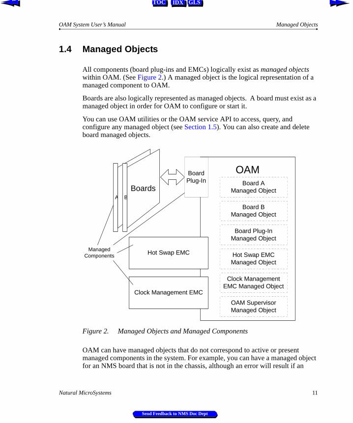
All components (board plug-ins and EMCs) logically exist as managed objects within OAM. (See Figure 2.) A managed object is the logical representation of a managed component to OAM.
Boards are also logically represented as managed objects. A board must exist as a managed object in order for OAM to configure or start it.
You can use OAM utilities or the OAM service API to access, query, and configure any managed object (see Section 1.5). You can also create and delete board managed objects.
Figure 2. Managed Objects and Managed Components
OAM can have managed objects that do not correspond to active or present managed components in the system. For example, you can have a managed object for an NMS board that is not in the chassis, although an error will result if an
A B
Boards
OAM
Clock Management EMC
BoardPlug-In
Hot Swap EMC
Board AManaged Object
Board BManaged Object
Board Plug-InManaged Object
Hot Swap EMCManaged Object
Clock ManagementEMC Managed Object
OAM SupervisorManaged Object
ManagedComponents
Natural MicroSystems 11
Send Feedback to NMS Doc Dept

Chapter 1 Introduction OAM System User’s Manual
IDX GLSTOC
attempt is made to start that component. Conversely, not all NMS resources in the system may exist as managed objects within OAM.
The OAM Supervisor has a managed object. You can access the Supervisor managed object to query and configure various system-level parameters. For more information, refer to the OAM Service Developer’s Reference Manual.
1.4.1 The Configuration Database
OAM maintains a configuration database to facilitate the management of the components under its control. Each hardware and software managed object has its own record in the database containing configuration parameters and parameter values. (See Figure 3.)
Figure 3. OAM Configuration Database
A B
Boards
OAM ConfigurationDatabase
Clock Management EMC
BoardPlug-In
Hot Swap EMC
Board AManaged Object
Board BManaged Object
Board Plug-InManaged Object
Hot Swap EMCManaged Object
Clock ManagementEMC Managed Object
BoardA
Board
Plug-In
Clock
Mgm
tH
otS
wap
OA
MS
upvB
oardB
OAM SupervisorManaged Object
Records
12 Natural MicroSystems
Send Feedback to NMS Doc Dept

OAM System User’s Manual Board Identification Methods
IDX GLSTOC
In the database, each parameter and value is expressed as a keyword name/value pair (for example, AutoStart = YES). You can query the OAM service for keyword values for any managed object. Keywords and values can be added, modified, or deleted.
1.4.2 Board Identification Methods
In the OAM system, each board is referenced using the following identifiers:
Æ A unique name.
Æ A board number. This is the typical way to identify a board in most NMS software products. Each board in a chassis has a unique board number.
Æ A unique PCI bus and slot in which the board is located.
The following secondary ID information is also available:
Æ A driver name/driver board ID combination. The driver name is unique among all driver names in the system. The driver board ID is unique among all boards accessed by a given driver. However, two boards accessed by different drivers may have the same driver board ID. The driver name/driver board ID together make up an ID for the board which is unique within the system.
Æ A serial number (if supported). This number is factory-configured, and may not be present for all boards.
Figure 4. Board Identification Options
Board
Board Number
PCI Bus:Slot
DriverName/BoardDriver ID
Serial Number
Name
Natural MicroSystems 13
Send Feedback to NMS Doc Dept

Chapter 1 Introduction OAM System User’s Manual
IDX GLSTOC
1.5 Accessing OAM Service Functions
You can access OAM functionality by using the:
Æ oamsys utility to perform system-wide configuration
Æ oamcfg utility to access individual OAM configuration functions
Æ oammon utility to perform OAM monitoring and alert notification functions
Æ oaminfo utility to retrieve and set keywords and values for a managed object
Æ OAM Service API to access all functionality programmatically
Figure 5 illustrates the relationships between these utilities and OAM:
Figure 5. OAM Utilities and OAM Service API
The following sections describe the utilities and API.
Note: To use any OAM utility, ctdaemon must be running, and must have the CT Access server started within it (see Chapter 4).
OAM ServiceAPI
OAM
oamcfgoamsys
oammon oaminfo
(customapplication)
ConfigurationDatabase
14 Natural MicroSystems
Send Feedback to NMS Doc Dept

OAM System User’s Manual oamsys
IDX GLSTOC
1.5.1 oamsys
To perform system-wide configuration and startup of managed components, use the oamsys utility. This utility creates managed objects and initializes the OAM database based on system configuration files you supply. It then attempts to start (boot) all boards which exist as managed objects.
Configuration parameter values for each managed object are listed in the system configuration file. If the managed object is a board, this information includes the board’s ID information.
oamsys completely renews the database each time it runs, and restarts all boards. Any parameters not listed in the configuration file are reset to their default settings. Thus oamsys makes it easy to track the configuration of an entire system.
Note: oamsys is a rough functional equivalent of the agmon utility. For details, see Appendix B.
To perform its tasks, the oamsys utility makes multiple calls to the oamcfg utility, described in Section 1.5.2.
1.5.2 oamcfg
oamcfg provides access to individual OAM configuration functions. Using this utility, you can cause OAM to:
Æ Create or delete managed objects for boards
Æ Specify settings for managed object parameters, either individually, or many at once using keyword files
Æ Start (boot) or stop (shut down) one or more boards
Æ Test boards (if supported)
Æ Display basic ID information for board managed objects
You can direct oamcfg to perform one or more operations for a single managed object. Alternatively, the utility can perform operations on all board managed objects in the database with one call.
oamcfg should be used for individual managed object updates. oamcfg can be cumbersome if used to update many managed objects in a complex system. Use oamsys for this purpose.
Natural MicroSystems 15
Send Feedback to NMS Doc Dept

Chapter 1 Introduction OAM System User’s Manual
IDX GLSTOC
1.5.3 oammon
The oammon utility allows access to OAM monitoring functions. Using oammon, you can:
Æ Monitor for board errors and other messages
Æ Capture these messages in a flat file
Æ Send a test alert notification message to all OAM client applications
1.5.4 oaminfo
The oaminfo utility allows you to access keywords from the command line. oaminfo can display all keywords for a managed object, or specific keywords and values. It can also search for text in keywords, and set keyword values. For more information about oaminfo, refer to the OAM Service Developer’s Reference Manual.
1.5.5 OAM Service API
You can access OAM functionality programmatically using the OAM service API. OAM is implemented as a service under the CT Access development environment. CT Access provides standard programming interfaces for hardware-independent functions. Under CT Access, logically related functions (OAM operations, for example) are divided into groups, called services, which have similar APIs.
OAM utilities make calls to the OAM service API to perform their operations.
For detailed information about programming using the OAM service API, refer to the OAM Service Developer’s Reference Manual.
16 Natural MicroSystems
Send Feedback to NMS Doc Dept

OAM System User’s Manual Installing OAM
IDX GLSTOC
1.6 Installing OAM
OAM is available as part of the Natural Access software package. This package is available on CD or on the NMS web site (www.nmss.com). To learn how to install the software, refer to the Natural Access installation booklet.
When OAM is installed, the following environment variables are set or modified automatically, unless you specify otherwise:
Under Windows NT, the following service is registered:
Æ NMS Clock Fallback Manager
Æ NMS HotSwap Manager
Note: Make sure to check the readme files included with the software for late-breaking information on all hardware and software products.
Environment Variable Setting/Modification
AGLOAD \nms\oam\cfg is appended to this variable (/opt/nms/oam/cfg in UNIX)
(UNIX only)LD_LIBRARY_PATH
/opt/nms/lib:/opt/nms/hotswap/lib (required by Hot Swap Manager)
Natural MicroSystems 17
Send Feedback to NMS Doc Dept

Chapter 1 Introduction OAM System User’s Manual
IDX GLSTOC
1.7 System Configuration Overview
Once you have installed the software, follow these steps to set up an OAM system:
Step Description Documented In...
1. Make sure that your chassis is set up properly for Hot-Swapping boards. (Required only if you are using Hot Swap.)
Chapter 2
2. Create a system configuration file describing your system. In this file, give each board a unique name and board number.
Chapter 3
3. If your system contains two or more boards connected through the H.100 or H.110 bus, configure clocking on the bus.
Appendix A
4. Start ctdaemon, if it is not already running. Also start the Hot Swap driver and manager.
Chapter 4
5. Use oamsys to create managed objects and initialize the OAM database based upon the system configuration file, and to start all installed boards.
Each configured board is now managed by OAM. To reference the board in the OAM service API or utilities, you can use either its name or its number.
Chapter 5
18 Natural MicroSystems
Send Feedback to NMS Doc Dept

IDX GLSTOC
Chapter 2
Setting Up the Chassis
2.1 Introduction 20
2.2 Hot Swap Overview 202.2.1 Hot Swap EMC 212.2.2 Hot Swap Platform Requirements 22
2.3 Setting Up Hot Swap 232.3.1 Making Sure a Chassis Supports Hot Swap 232.3.2 Setting Up Your Chassis for Hot Swap 23
PCI Bus Segments and Space Windows 23Using Leftover Allocated Space 24
2.4 Determining Bus and Slot Locations 27
2.5 Configuring the H.100 or H.110 Bus Clock 282.5.1 Clock Management EMC 28
Natural MicroSystems 19
Send Feedback to NMS Doc Dept

Chapter 2 Setting Up the Chassis OAM System User’s Manual
IDX GLSTOC
2.1 Introduction
This chapter provides a general description of how to set up your system so that:
Æ The maximum number of slots are available for Hot Swap.
Æ A CT bus clock is properly configured to synchronize communications between boards.
For specifics on configuring a particular board type, refer to the board’s documentation.
2.2 Hot Swap Overview
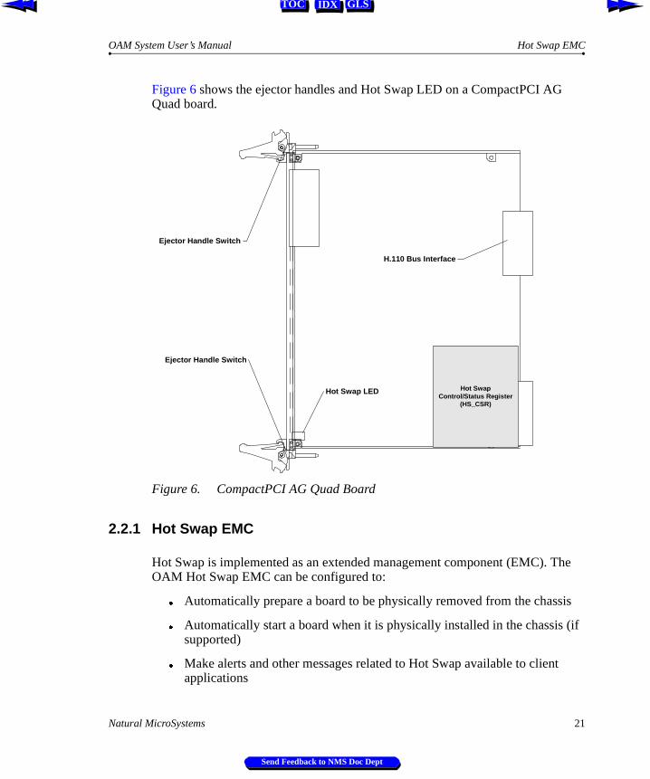
Hot Swap functionality is an integral part of OAM. Hot Swap is designed for use with CompactPCI Hot Swap-compliant boards. These boards contain a switch built into the ejector handle and a front panel Hot Swap LED. Upon insertion, the switch signals that the board is fully seated (with the handle closed) and that software connection can be initiated. Upon extraction, the switch signals that the operator is beginning to extract the board and that software disconnection should be initiated.
When lit, the Hot Swap LED informs the operator that software disconnection is complete and extraction is permitted. The operator can open the handle the rest of the way, ejecting the board.
The PCI interface for NMS Hot Swap-compatible CompactPCI boards includes the Hot Swap Control/ Status Register (HS_CSR). The PCI interface is responsible for management of the ejector handle switches and the Hot Swap LED. This interface also supports control of the hardware connection process for a High Availability system.
20 Natural MicroSystems
Send Feedback to NMS Doc Dept
OAM System User’s Manual Hot Swap EMC
IDX GLSTOC
Figure 6 shows the ejector handles and Hot Swap LED on a CompactPCI AG Quad board.
Figure 6. CompactPCI AG Quad Board
2.2.1 Hot Swap EMC
Hot Swap is implemented as an extended management component (EMC). The OAM Hot Swap EMC can be configured to:
Æ Automatically prepare a board to be physically removed from the chassis
Æ Automatically start a board when it is physically installed in the chassis (if supported)
Æ Make alerts and other messages related to Hot Swap available to client applications
Hot Swap LED
Ejector Handle Switch
Ejector Handle Switch
Hot SwapControl/Status Register
(HS_CSR)
H.110 Bus Interface
Natural MicroSystems 21
Send Feedback to NMS Doc Dept

Chapter 2 Setting Up the Chassis OAM System User’s Manual
IDX GLSTOC
The Hot Swap EMC communicates with the Hot Swap Manager and driver to perform Hot Swap operations. The Hot Swap Manager and driver must be started in order for Hot Swap operations to work. To learn how to start these components, refer to Chapter 4.
Note: Hot Swap is supported only with CompactPCI boards. Some CompactPCI boards do not support Hot Swap. To determine if a board model supports Hot Swap, refer to the documentation for the board. Note that removing a non-Hot Swap-compatible board while the system is running may cause serious damage to the board and to the system.
2.2.2 Hot Swap Platform Requirements
Hot Swap development requires an Intel or SPARC CompactPCI-compliant platform that conforms to the following specifications:
Æ PICMG 2.0 Revision 2.1 CompactPCI
Æ PICMG 2.1 Revision 1.0 CompactPCI Hot Swap (either Hot Swap or High Availability platform)
Æ PCI BIOS Revision 2.1 (PCI BIOS services are used to manage interrupt assignments for hot-inserted boards.)
Æ PICMG 2.5 Revision 1.0 CompactPCI Computer Telephony (If the H.110 bus is not present, the CompactPCI board will not power up.)
22 Natural MicroSystems
Send Feedback to NMS Doc Dept
OAM System User’s Manual Setting Up Hot Swap
IDX GLSTOC
2.3 Setting Up Hot Swap
The following sections describe how to determine if a chassis supports Hot Swap, and make sure that adequate address space is configured for the boards.
2.3.1 Making Sure a Chassis Supports Hot Swap
To determine if a chassis is compatible with Hot Swap, run the biostest utility, as follows:
1. Start biostest by entering: biostest
2. Verify that the next line in the display is:
THIS SYSTEM IS HOT SWAP COMPATIBLE
For more details on biostest, see Chapter 8.
2.3.2 Setting Up Your Chassis for Hot Swap
In order to allow hot-swapping of boards in your CompactPCI system, adequate address space must be preconfigured. To maximize the number of slots available for hot-swapping, you should:
Æ Have all slots populated at boot time, or
Æ Have no slots populated at boot time.
This section describes how space is allocated for hot-swapping.
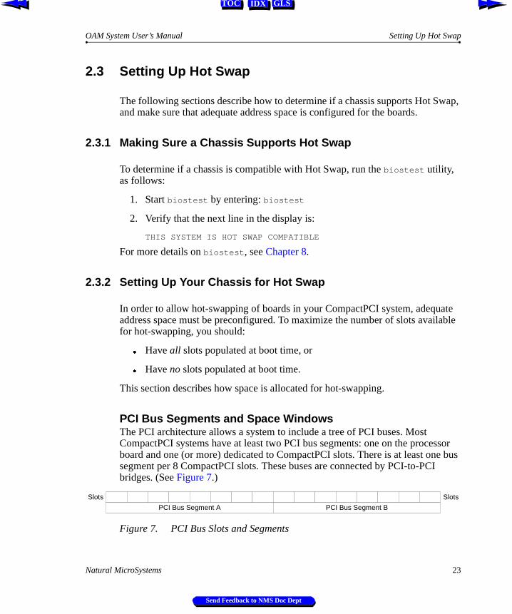
PCI Bus Segments and Space WindowsThe PCI architecture allows a system to include a tree of PCI buses. Most CompactPCI systems have at least two PCI bus segments: one on the processor board and one (or more) dedicated to CompactPCI slots. There is at least one bus segment per 8 CompactPCI slots. These buses are connected by PCI-to-PCI bridges. (See Figure 7.)
Figure 7. PCI Bus Slots and Segments
PCI Bus Segment A PCI Bus Segment B
Slots Slots
Natural MicroSystems 23
Send Feedback to NMS Doc Dept

Chapter 2 Setting Up the Chassis OAM System User’s Manual
IDX GLSTOC
Each device requires a certain amount of address space on the bridges. At boot time, the system BIOS configures address space “windows” on each bridge to define the range of addresses (that is, the bus number or memory address) that are allocated behind that bridge. (See Figure 8.)
Figure 8. Segments and Allocated Address Space on Bridge
Boards can only be hot-inserted into slots for which memory has been preallocated. Memory is usually allocated as follows:
Æ If any devices are physically installed at boot time, the bridge windows are initialized to be just big enough to span the address spaces that have been allocated to these devices behind the bridge. In this case, boards can only be hot-inserted into slots that were populated at boot time. (This is true unless the boards can fit into leftover allocated space, as described in the following section.)
Æ If no devices are physically installed at boot time, a single large bridge window is initialized that can accommodate any number of boards that can fit into it. This window is 16 MB under Windows NT; 64 MB under UNIX.
Thus to maximize the number of slots available for hot-swapping, you should have all slots populated at boot time; or have no slots populated at boot time.
Using Leftover Allocated SpaceUsually, each address space window cannot be less than 1 MB in size. If allocations to boards behind the bridge do not add up to an integral number of megabytes, some fraction of a megabyte will be available in the window and unallocated. This unallocated space is then available for insertion of additional boards whose address space requirements are small enough. For example, if a board requires two 128K memory regions, and a CompactPCI bus segment contains only one of these boards at boot time, hot-insertion of up to 3 additional boards into that segment can be accommodated (see Figure 9).
PCI Bus Segment A PCI Bus Segment B
Slots Slots
Address space on bridge, allocated to segment A Address space on bridge, allocated to segment B
24 Natural MicroSystems
Send Feedback to NMS Doc Dept

OAM System User’s Manual Setting Up Your Chassis for Hot Swap
IDX GLSTOC
Figure 9. Bus with 256K Board Inserted
However, if an 8-slot segment has 4 slots occupied at boot time with the boards, no more boards can be hot-inserted into that segment, because 4 boards occupy exactly one megabyte of address space. (See Figure 10.)
Figure 10. Bus with Four 256K Boards Inserted
PCI Bus Segment A PCI Bus Segment B
Slots Slots
Uninitialized
Address space on bridge, allocated to segment A Address space on bridge, allocated to segment B
PC
I Board X
requiring two
128K m
emory regions
256Kallocatedfor board
768K available for swapping inother boards
Setup at Boot Time
Memory at Run Time
PCI Bus Segment A PCI Bus Segment B
Slots Slots
Uninitialized
Address space on bridge, allocated tosegment A
Address space on bridge, allocated tosegment B
PC
I Board X
requiring two
128K m
emory regions
1 MB allocated for board
Setup at Boot Time
Memory at Run Time
PC
I Board X
requiring two
128K m
emory regions
PC
I Board X
requiring two
128K m
emory regions
PC
I Board X
requiring two
128K m
emory regions
Natural MicroSystems 25
Send Feedback to NMS Doc Dept

Chapter 2 Setting Up the Chassis OAM System User’s Manual
IDX GLSTOC
Some boards (such as the CG 6000C board) have an address space requirement of two 1 MB memory regions. Since this requirement exactly matches the 1 MB granularity, you cannot add more of these boards than were present at start-up without rebooting. (See Figure 11.)
Figure 11. Bus with CG 6000C Board Inserted
The biostest utility (described in Chapter 8) reports on each PCI-to-PCI bridge in a system and its memory window assignment (if any).
PCI Bus Segment A PCI Bus Segment B
Slots Slots
Address space on bridge, allocated tosegment A
Address space on bridge, allocated tosegment B
CG
6000C requiring tw
o1 M
B m
emory regions
1 MB allocated for board
Setup at Boot Time
Memory at Run Time
1 MB allocated for board
26 Natural MicroSystems
Send Feedback to NMS Doc Dept

OAM System User’s Manual Determining Bus and Slot Locations
IDX GLSTOC
2.4 Determining Bus and Slot Locations
The utility pciscan displays the logical CompactPCI or PCI bus and slot information for each NMS board installed in the system. To determine the bus and slot numbers for each board:
1. Insert a CompactPCI board into an unidentified slot.
2. Run pciscan by entering: pciscan
The pciscan output will be similar to the following:
Bus Slot NMS ID--- ---- ------ 2 11 0x50d AG CPCI Quad T1 2 13 0x6000 CG 6000 2 14 0--- ---- -- ----------------There were 3 NMS PCI board(s) detected
3. Record the CompactPCI bus and slot numbers.
4. Repeat steps 1 to 3 for each bus slot.
pciscan may also be used to flash an LED on a specific board. See Chapter 8 for complete details on pciscan.
A chart like the following is useful when mapping out the CompactPCI chassis:
Figure 12. CompactPCI Chassis Mapping
Front of Chassis
Back of Chassis
Left Right
Type
Bus
Slot
Type
Bus
Slot
Type
Bus
Slot
Type
Bus
Slot
Type
Bus
Slot
Type
Bus
Slot
Type
Bus
Slot
Type
Bus
Slot
Type
Bus
Slot
Type
Bus
Slot
Natural MicroSystems 27
Send Feedback to NMS Doc Dept

Chapter 2 Setting Up the Chassis OAM System User’s Manual
IDX GLSTOC
2.5 Configuring the H.100 or H.110 Bus Clock
If your boards are connected to each other on the H.100 or H.110 bus, a bus clock must be set up to synchronize communications between the boards connected to the bus. In addition, to provide redundant and fault-tolerant clocking between devices on the bus, alternative (fallback) clock sources can be configured to provide the clock signal if the primary source fails.
To configure the bus clock for your system:
Æ Configure a board to act as clock master, driving the bus clock.
Æ (Optional) Configure another board to act as secondary clock master, driving the clock if the primary clock master fails.
Æ Configure primary and secondary timing references for each clock master board. The timing reference for a board is an external signal from which it can derive a clock pulse.
Æ Configure all other boards as clock slaves, so they synchronize to the clock master signal.
To configure a board, modify the clocking keywords in the board’s managed object. For a general introduction to clocking, see Appendix A. For specifics on setting up clocking for your boards, refer to your board documentation.
2.5.1 Clock Management EMC
The OAM service provides H.100 and H.110 bus clock management services to boards in a chassis that are connected through the bus. This functionality is provided in the Clock Management EMC.
When the boards are started, the Clock Management EMC:
Æ Configures the clock on each board as specified in the OAM database.
Æ Makes sure that the bus clock master board (the board driving the clock) is running before any clock slave boards start up.
28 Natural MicroSystems
Send Feedback to NMS Doc Dept
IDX GLSTOC
Chapter 3
Creating OAM Configuration Files
3.1 Introduction 30
3.2 Configuration File Overview 30
3.3 Creating a System Configuration File 313.3.1 Specifying Configurations for Boards 32
Mandatory Statements 32Specifying Keyword Files for Boards 32
3.3.2 Specifying Configurations for Non-Board Objects 333.3.3 Sample System Configuration File 34
3.4 Keyword Files 353.4.1 Keyword File Syntax 353.4.2 Sample Keyword File 36
3.5 Keywords 373.5.1 Keyword Name/Value Pairs 373.5.2 Struct Keywords 373.5.3 Array Keywords 383.5.4 Array Keyword Expansion 39
Natural MicroSystems 29
Send Feedback to NMS Doc Dept

Chapter 3 Creating OAM Configuration Files OAM System User’s Manual
IDX GLSTOC
3.1 Introduction
Once you have determined the internal layout of your system, create OAM configuration files describing the layout. Then run oamsys to initialize the OAM database based on the information in the file.
This chapter describes how to create configuration files. The following chapters describe how to start CT Access and run oamsys to complete the process.
3.2 Configuration File Overview
To set up OAM, create a system configuration file. This file contains:
Æ A list of boards in the system.
Æ For each board, the name of one or more keyword files containing parameters and values to configure the board (see Figure 13). These settings are expressed as keyword name/value pairs.
Æ You can also includes sections to configure non-board managed objects (such as an EMC or the Supervisor). For more information, see Section 3.3.2.
When oamsys runs, a managed object is created for each board. A record is created for each object in the OAM database, containing default parameter settings. Then the settings in the configuration files are added to the record.
If your system contains more than one board with the same configuration, you can use the same keyword file for each of these boards.
Several sample keyword files are supplied with your hardware installation. Each of these files configures the board to use a different protocol (for example, wink start or off-premises station). You can reference these files in your system configuration file, or modify them if you wish. For more information about the sample files supplied for your hardware, refer to the hardware documentation.
30 Natural MicroSystems
Send Feedback to NMS Doc Dept

OAM System User’s Manual Creating a System Configuration File
IDX GLSTOC
Figure 13. OAM Configuration Files
3.3 Creating a System Configuration File
A system configuration file is an ASCII text file. Typically, this file is named oamsys.cfg. By default, oamsys looks for a file with this name when it starts up.
Note: The syntax of system configuration files used by oamsys is significantly different from the AG configuration files used by agmon. Configuration files are not interchangeable between oamsys and agmon. For more information about migration from agmon configuration files, refer to Appendix B.
A sample system configuration file can be found in:
Æ Windows NT: nms\oam\cfg\oamsys.cfg
Æ UNIX: /opt/nms/oam/cfg/oamsys.cfg
Statements within the system configuration file appear one to a line. Any text appearing after a pound sign (#) is a comment, and is ignored. Statements in all configuration files are case-insensitive, except where operating system conventions prevail (for example, filenames under UNIX).
System Configuration Fileoamsys.cfg
oamsys OAMConfiguration
Database
Keyword Filefilea.cfg
TCPFILE[0]=NOCCCountry=USATrunk[0-3].TrunkType=T1DSP[0-31].File[1]=toneResource[0].Name=RSC1Resource[0].Size=120Resource[0].TCPNum=1...
[Board A]Product=CG6000_QUADNumber=1Bus=0Slot=20File=filea.cfg
[Board B]Product=CG6000_QUADNumber=2Bus=0Slot=21File=fileb.cfg
[Supervisor]AutoStartEnabled=YesAutoStopEnabled=Yes
Keyword Filefileb.cfg
TCPFILE[0]=NOCCCountry=USATrunk[0-3].TrunkType=T1DSP[0-31].File[1]=toneResource[0].Name=RSC1Resource[0].Size=120Resource[0].TCPNum=1...
Natural MicroSystems 31
Send Feedback to NMS Doc Dept

Chapter 3 Creating OAM Configuration Files OAM System User’s Manual
IDX GLSTOC
3.3.1 Specifying Configurations for Boards
The system configuration file is divided into multiple sections, one for each board. Each section is headed with the name of the board, in square brackets ([ ]):
[My board]
Note: Board names must be unique.
Below each board name are statements which apply to the board. Each statement appears on its own line. Each statement consists of a keyword name, followed by an equals sign (=) and then a value:
keyword_name=value
Mandatory StatementsIn the section for each board, the following statements must appear:
Specifying Keyword Files for BoardsTo specify a keyword file for the board, use the File keyword:
File = myfile.cfg
You can specify more than one keyword file. Specify the filenames on a single line following the File keyword, separated by whitespace:
File = file1.cfg file2.cfg file3.cfg
Alternatively, you can specify multiple File keywords, one to a line:
File = file1.cfgFile = file2.cfgFile = file3.cfg
Keyword Description
Product The name of the board product. To learn how to retrieve a list of valid strings to use here, see Section 6.3.1.
Number The board number. Use any integer from 0 to 32767. Each board’s number must be unique.
Bus The PCI bus number. The bus:slot location for each board must be unique.
Slot The PCI slot number. The bus:slot location for each board must be unique.
32 Natural MicroSystems
Send Feedback to NMS Doc Dept

OAM System User’s Manual Specifying Configurations for Non-Board Objects
IDX GLSTOC
To include embedded whitespace in a filename, surround the name with quotation marks:
File = "My Configuration File.cfg"
By default, oamsys searches for the keyword files listed with this keyword in the same way it searches for the system configuration file itself (see Section 5.2.1). To reference a file in another directory, specify the directory along with the filename:
File = c:\mycyf\file1.cfg
Keywords are set in the order in which oamsys encounters them in the files. Specifying a setting for a keyword in more than one file is not recommended.
Note: In addition to (or instead of) keyword file names, you can specify keyword settings for a board directly in the board’s section in the system configuration file. Use the keyword syntax described in Section 3.5.
3.3.2 Specifying Configurations for Non-Board Objects
In addition to sections for boards, the system configuration file can include sections containing configuration information for non-board objects (such as EMCs, board plug-ins, or the OAM Supervisor).
The section for each object is headed with the object’s name, in square brackets([ ]):
[Supervisor]
The object name for the OAM Supervisor is Supervisor. The object name for a plug-in or EMC is its filename (for example, hotswap.emc).
Below each board name are keyword settings, specified as described in Section 3.5. For example:
[Supervisor]AutoStartEnabled=YesAutoStopEnabled=Yes
The File statement can also be used here, to specify a keyword file containing settings for the object:
[Supervisor]File=supvparms.cfg
To learn what keywords can be set for board plug-ins, refer to the board-specific documentation. To learn what keywords can be set for EMCs or the OAM Supervisor, refer to the OAM Service Developer’s Reference Manual.
Natural MicroSystems 33
Send Feedback to NMS Doc Dept

Chapter 3 Creating OAM Configuration Files OAM System User’s Manual
IDX GLSTOC
3.3.3 Sample System Configuration File
The following system configuration file describes two CG 6000C boards, one at bus 0, slot 20, and the other at bus 0, slot 21. The first board is assigned keyword file a6wnk.cfg, which sets up the board to use the wink start protocol. The second board uses keyword file a6ops.cfg, which sets up the board to use the off station premises protocol. Supervisor keywords are set to cause boards to auto-start when the system boots or when they are Hot Swap inserted, and to auto-stop when the system shuts down:
# This is the OAM system configuration file.# It describes all the boards in my system.
[My board]Product = CG6000_QUADNumber = 1Bus = 0Slot = 20File = a6wnk.cfg #Wink Start protocol
[My other board]Product = CG6000_QUADNumber = 2Bus = 0Slot = 21File = a6ops.cfg #Off Premises Station protocol
[Supervisor]AutoStartEnabled=YesAutoStopEnabled=Yes
34 Natural MicroSystems
Send Feedback to NMS Doc Dept

OAM System User’s Manual Keyword Files
IDX GLSTOC
3.4 Keyword Files
A keyword file contains keyword settings. When you create your system configuration file, you can reference one or more keyword files to use for the boards in your system (see Section 3.3). When you run oamsys, the utility adds the settings for each board to the OAM database.
Several sample keyword files are supplied with your hardware installation. Each of these files configures the board to use a different protocol (for example, wink start or off-premises station). You can reference these files in your system configuration file, or modify them if you wish. For more information about the sample files supplied for your hardware, refer to the hardware documentation.
For detailed descriptions of the keywords supported for your board, refer to the board-specific documentation.
Note: If your system contains more than one board with the same configuration, you can use the same keyword file for each of these boards.
3.4.1 Keyword File Syntax
A keyword file is an ASCII text file. Typically, the file has the extension .cfg.
Within the file, each statement appears on its own line. A line beginning with a pound sign (#) denotes a comment, and is ignored. If a line ends with a backslash (\), the next line is assumed to be a continuation of the line.
Note: The syntax of keyword files is significantly different from that used by agmon. Keyword files are not interchangeable between OAM and agmon. For more information about migration from agmon configuration files, refer to Appendix B.
Natural MicroSystems 35
Send Feedback to NMS Doc Dept
Chapter 3 Creating OAM Configuration Files OAM System User’s Manual
IDX GLSTOC
3.4.2 Sample Keyword File
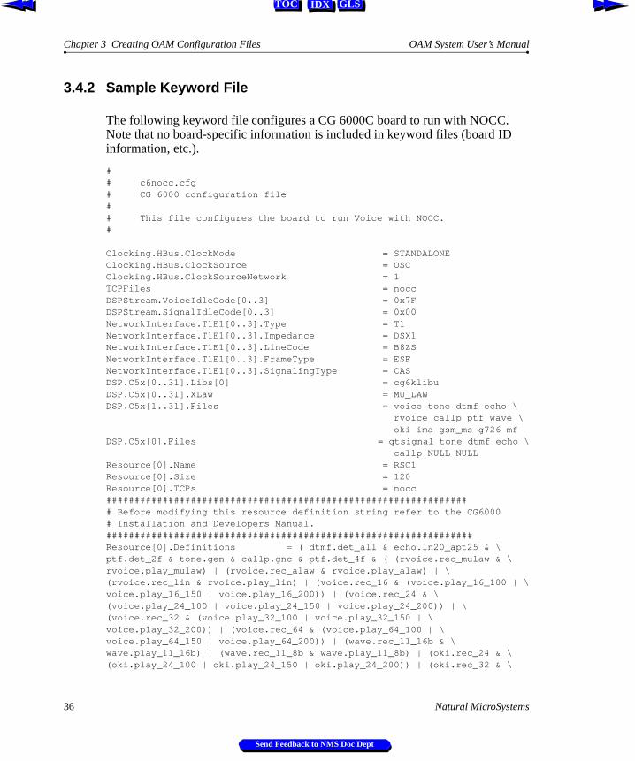
The following keyword file configures a CG 6000C board to run with NOCC. Note that no board-specific information is included in keyword files (board ID information, etc.).
## c6nocc.cfg# CG 6000 configuration file## This file configures the board to run Voice with NOCC.# Clocking.HBus.ClockMode = STANDALONEClocking.HBus.ClockSource = OSCClocking.HBus.ClockSourceNetwork = 1TCPFiles = noccDSPStream.VoiceIdleCode[0..3] = 0x7FDSPStream.SignalIdleCode[0..3] = 0x00NetworkInterface.T1E1[0..3].Type = T1NetworkInterface.T1E1[0..3].Impedance = DSX1NetworkInterface.T1E1[0..3].LineCode = B8ZSNetworkInterface.T1E1[0..3].FrameType = ESFNetworkInterface.T1E1[0..3].SignalingType = CASDSP.C5x[0..31].Libs[0] = cg6klibuDSP.C5x[0..31].XLaw = MU_LAWDSP.C5x[1..31].Files = voice tone dtmf echo \ rvoice callp ptf wave \ oki ima gsm_ms g726 mfDSP.C5x[0].Files = qtsignal tone dtmf echo \ callp NULL NULLResource[0].Name = RSC1Resource[0].Size = 120Resource[0].TCPs = nocc################################################################# Before modifying this resource definition string refer to the CG6000 # Installation and Developers Manual.#################################################################Resource[0].Definitions = ( dtmf.det_all & echo.ln20_apt25 & \ptf.det_2f & tone.gen & callp.gnc & ptf.det_4f & ( (rvoice.rec_mulaw & \rvoice.play_mulaw) | (rvoice.rec_alaw & rvoice.play_alaw) | \(rvoice.rec_lin & rvoice.play_lin) | (voice.rec_16 & (voice.play_16_100 | \voice.play_16_150 | voice.play_16_200)) | (voice.rec_24 & \(voice.play_24_100 | voice.play_24_150 | voice.play_24_200)) | \(voice.rec_32 & (voice.play_32_100 | voice.play_32_150 | \voice.play_32_200)) | (voice.rec_64 & (voice.play_64_100 | \voice.play_64_150 | voice.play_64_200)) | (wave.rec_11_16b & \wave.play_11_16b) | (wave.rec_11_8b & wave.play_11_8b) | (oki.rec_24 & \(oki.play_24_100 | oki.play_24_150 | oki.play_24_200)) | (oki.rec_32 & \
36 Natural MicroSystems
Send Feedback to NMS Doc Dept

OAM System User’s Manual Keywords
IDX GLSTOC
(oki.play_32_100 | oki.play_32_150 | oki.play_32_200)) | (ima.rec_24 & \ima.play_24) | (ima.rec_32 & ima.play_32) | (gsm_ms.frgsm_rec & \gsm_ms.frgsm_play) | g726.rec_32 | g726.play_32) )DLMFiles[0] = cg6krunDebugMask = 0x0
3.5 Keywords
This section describes the different types of keywords, and how you can specify them in configuration files.
3.5.1 Keyword Name/Value Pairs
In its simplest form, a statement consists of a keyword name, followed by an equals sign (=) and then a value:
keyword_name= value
keyword_name denotes a parameter, and value indicates the value to assign the parameter:
AutoStart = YES
For a list of valid keywords for a managed object, see the manual for the device you are configuring. OAM Supervisor keywords, Clock Management EMC keywords, and Hot Swap EMC keywords are listed in the OAM Service Developer’s Reference Manual.
3.5.2 Struct Keywords
Many keywords are organized into groups, called structs. Keywords within the struct have related functionality. Each struct has a name. The keyword name for each keyword in the struct consists of the struct name, followed by a period (.) and then the keyword (see Figure 14). The struct name within each keyword name is a Struct keyword:
Natural MicroSystems 37
Send Feedback to NMS Doc Dept

Chapter 3 Creating OAM Configuration Files OAM System User’s Manual
IDX GLSTOC
Figure 14. Struct Keyword Names
Structs can contain structs. In the following example, struct Clocking contains structs Hbus and MVIP:
Clocking.HBus.ClockMode = MASTER_AClocking.HBus.AutoFallBack = YESClocking.MVIP.ClockRef = SEC8KClocking.MVIP.AutoFallBack = NO
In this example, Clocking, Hbus, and MVIP are Struct keywords.
3.5.3 Array Keywords
Many keywords are organized into arrays: lists of items of the same type. Each element of the array can have a unique value.
The index for an array keyword appears as a suffix, surrounded by square brackets. Each index is zero-based:
TCPFile[0] = nocc
A struct can contain arrays:
DSPStream.SignalIdleCode[0] = 0x00DSPStream.VoiceIdleCode[0] = 0x00DSPStream.SignalIdleCode[1] = 0x00DSPStream.VoiceIdleCode[1] = 0x00
It is also possible to have an array of structs:
Resource[0].Name = RSC1Resource[0].Size = 120Resource[0].FileName[0] = myfile.fooResource[0].FileName[1] = myfile2.fooResource[0].SpanEnable=AUTOResource[1].Name = RSC1Resource[1].Size = 60Resource[1].FileName[0] = myfile.fooResource[1].SpanEnable=AUTO
Driver.NameDriver.BoardID
Struct keyword
Keyword name
= QX2000= 2
Value
38 Natural MicroSystems
Send Feedback to NMS Doc Dept

OAM System User’s Manual Array Keyword Expansion
IDX GLSTOC
For any array keyword xxx, xxx.Count indicates the number of elements in the array. For example:
Resource.Count=2
xxx.Count is automatically updated for each element added or removed from an array. This value cannot be set directly.
3.5.4 Array Keyword Expansion
For convenience, there is a shorthand method of assigning values to keywords in an array.
Note: oamcfg performs keyword expansion, not OAM. When specifying keywords and values using the OAM service API, do not use this keyword expansion syntax.
Multiple keyword names can be assigned the same value in a single line, as follows:
Statement Expanded Equivalent
keyword[0..2] = value keyword[0] = valuekeyword[1] = valuekeyword[2] = value
keyword[0-2] = value (same as above)
keyword[1,3,5] = value keyword[1] = valuekeyword[3] = valuekeyword[5] = value
keyword[0..3,5..7,9] = value keyword[0] = valuekeyword[1] = valuekeyword[2] = valuekeyword[3] = valuekeyword[5] = valuekeyword[6] = valuekeyword[7] = valuekeyword[9] = value
Natural MicroSystems 39
Send Feedback to NMS Doc Dept

Chapter 3 Creating OAM Configuration Files OAM System User’s Manual
IDX GLSTOC
In a keyword name consisting of multiple array keywords separated by periods, a separate range can be specified for each keyword in the name:
Multiple values for keywords in an array can be specified on a single line, separated by whitespace. To include whitespace in a value, the value is surrounded with quotation marks. Values are assigned to keywords in numerical order, starting with 0. The array keyword is specified without the square brackets or index value (for example, Resource for Resource[x]):
Statement Expanded Equivalent
kywd1[1].kywd2[1..2] = value kywd1[1].kywd2[1] = valuekywd1[1].kywd2[2] = value
kywd1[1..3].kywd2[1..2] = value kywd1[1].kywd2[1] = valuekywd1[1].kywd2[2] = valuekywd1[2].kywd2[1] = valuekywd1[2].kywd2[2] = valuekywd1[3].kywd2[1] = valuekywd1[3].kywd2[2] = value
Statement Expanded Equivalent
keyword = val1 val2 val1 val4 keyword[0] = val1keyword[1] = val2keyword[2] = val1keyword[3] = val4
keyword = val1 val2 "val 1" val4 keyword[0] = val1keyword[1] = val2keyword[2] = "val 1"keyword[3] = val4
kywd1[1..3].kywd2[1..2].list = val1 val2 kywd1[1].kywd2[1].list[0] = val1kywd1[1].kywd2[1].list[1] = val2kywd1[1].kywd2[2].list[0] = val1kywd1[1].kywd2[2].list[1] = val2kywd1[2].kywd2[1].list[0] = val1kywd1[2].kywd2[1].list[1] = val2kywd1[2].kywd2[2].list[0] = val1kywd1[2].kywd2[2].list[1] = val2kywd1[3].kywd2[1].list[0] = val1kywd1[3].kywd2[1].list[1] = val2kywd1[3].kywd2[2].list[0] = val1kywd1[3].kywd2[2].list[1] = val2
40 Natural MicroSystems
Send Feedback to NMS Doc Dept

IDX GLSTOC
Chapter 4
Starting Hot Swap and ctdaemon
4.1 Introduction 42
4.2 Starting the Hot Swap Driver and Hot Swap Manager 424.2.1 Starting Hot Swap Under Windows NT 424.2.2 Starting Hot Swap Under UNIX 43
4.3 Starting the CT Access Server 44
4.4 Verifying Hot Swap 45
Natural MicroSystems 41
Send Feedback to NMS Doc Dept

Chapter 4 Starting Hot Swap and ctdaemon OAM System User’s Manual
IDX GLSTOC
4.1 Introduction
To start up OAM, start the following components:
Æ (If your hardware supports Hot Swap) the Hot Swap driver and Hot Swap Manager. OAM Hot Swap operations require that these components be running.
Æ The CT Access server (ctdaemon). OAM will only operate if ctdaemon is running.
This chapter describes how to start these components.
4.2 Starting the Hot Swap Driver and Hot Swap Manager
The following sections describe procedures for starting the Hot Swap driver and Manager under Windows NT and UNIX. See Chapter 8 for more details on the Hot Swap Driver service (hssrv) and the Hot Swap Manager (hsmgr).
Note: If you stop the Hot Swap driver, reboot your system before starting it again.
4.2.1 Starting Hot Swap Under Windows NT
When CT Access is installed, the Hot Swap driver is installed as a Windows NT driver. The Hot Swap Manager is also installed as a Windows NT service. Both are configured to be started manually.
The Hot Swap Manager is dependent on the Hot Swap driver. Therefore, starting Hot Swap Manager as a Windows NT service automatically starts the Hot Swap driver.
To start the Hot Swap Manager, enter:
net start hsmgr
42 Natural MicroSystems
Send Feedback to NMS Doc Dept

OAM System User’s Manual Starting Hot Swap Under UNIX
IDX GLSTOC
You can set the Hot Swap Manager to start automatically using the Windows NT Control Panel Services applet. To do so:
1. Open the Services applet in the Control Panel.
2. Highlight NMS HotSwap Manager.
3. Click the Startup... button.
4. Set the startup type to Automatic.
5. Click Close.
4.2.2 Starting Hot Swap Under UNIX
When CT Access is installed, the Hot Swap Driver and Hot Swap Manager are placed in the /opt/nms/hotswap/bin directory. These services can be started as daemons or as console applications.
Note: The Hot Swap Manager requires the LD_LIBRARY_PATH variable to be set to LD_LIBRARY_PATH = /opt/nms/lib:/opt/nms/hotswap/lib.
To start the Hot Swap applications in console mode:
1. Start the Hot Swap Driver by entering:
/opt/nms/hotswap/bin/hssrv
2. Start the Hot Swap Manager by entering:
/opt/nms/hotswap/bin/hsmstart
This script sets the LD_LIBRARY_PATH variable, and starts the Hot Swap Manager in console mode.
To start the Hot Swap applications as daemons:
1. Start the Hot Swap Driver in daemon mode by entering:
/opt/nms/hotswap/bin/hssrv -d
2. Make sure the LD_LIBRARY_PATH variable is set as described above.
3. Start the Hot Swap Manager in daemon mode by entering:
/opt/nms/hotswap/bin/hsmgr -d
Natural MicroSystems 43
Send Feedback to NMS Doc Dept

Chapter 4 Starting Hot Swap and ctdaemon OAM System User’s Manual
IDX GLSTOC
To run the services in daemon mode at boot time (recommended), edit your /etc/inittab file to include lines which set the LD_LIBRARY_PATH variable and then start the Hot Swap Driver and Manager. In this case, do not include the -d command-line option. For more information about the inittab file, refer to the UNIX administrator manuals.
Note: The Hot Swap Driver service must be started before the Hot Swap Manager.
4.3 Starting the CT Access Server
Before you use OAM or any related utility, start the CT Access server (ctdaemon), as follows:
Æ (Windows NT) You can start ctdaemon in any of the following ways:
- Access a command prompt, and enter:
net start ctdaemon
- In the Windows Control Panel, double-click on Services, and start the CT Access server within this applet.
- For console interaction with the NMS ctdaemon Windows NT service, invoke ctdaemon -c from any command prompt while the service is running.
Æ (Windows NT or UNIX) Invoke ctdaemon -i from the command prompt. This method allows full console interaction with the ctdaemon.
Note: In order for the OAM Supervisor to start up within the CT Access server when it boots, the following line must appear in the [ctasys] section in cta.cfg (this line is included by default):
Service = oam, oammgr
ctdaemon must be running for OAM functions, and other Server mode operations, to be available. If ctdaemon is stopped, all dependent applications will receive an error. The service may need to be stopped and restarted for OAM functions to become available again. Note that applications accessing CT Access in Library mode only will not be affected if ctdaemon is shut down.
44 Natural MicroSystems
Send Feedback to NMS Doc Dept
OAM System User’s Manual Verifying Hot Swap
IDX GLSTOC
4.4 Verifying Hot Swap
Once you have started the Hot Swap Manager and driver, use hsmon to verify that all Hot Swap files are installed and the Hot Swap driver and the Hot Swap manager are running. To run hsmon:
1. Start hsmon by entering:
hsmon
2. If you open the ejector handles on a CompactPCI board, messages reporting the extraction are displayed. For example:
< 1,9 HSM_BOARD_EXTRACTION_CONFIGURED
3. If you insert a CompactPCI board, messages reporting the insertion are displayed. For example:
< 1,9 HSM_BOARD_CONFIGURED< 1,9 HSM_BOARD_READY
4. Press S to stop hsmon.
For more details on hsmon, see Chapter 8.
Natural MicroSystems 45
Send Feedback to NMS Doc Dept

Chapter 4 Starting Hot Swap and ctdaemon OAM System User’s Manual
IDX GLSTOC
46 Natural MicroSystems
Send Feedback to NMS Doc Dept

IDX GLSTOC
Chapter 5
Using oamsys
5.1 Introduction 48
5.2 Using oamsys 485.2.1 Launching oamsys 48
Natural MicroSystems 47
Send Feedback to NMS Doc Dept

Chapter 5 Using oamsys OAM System User’s Manual
IDX GLSTOC
5.1 Introduction
This chapter describes how to use the oamsys utility to set up the OAM database, based upon parameter values specified in a system configuration file. (To learn how to create a system configuration file, refer to Chapter 3.)
5.2 Using oamsys
To perform system-wide configuration and startup of boards, use the oamsys utility. This utility:
Æ Stops any currently operating boards.
Æ Creates managed objects, and initializes the OAM database based on a system configuration file you supply. Any existing board-specific data in the database is deleted and replaced with the contents of the system configuration file. For more information about system configuration files, see Chapter 3.
Æ Attempts to start (boot) all board managed objects.
To perform its tasks, the oamsys utility makes multiple calls to the oamcfg utility, described in Chapter 6.
To use oamsys, ctdaemon must be running. To learn how to start CT Access in this mode, refer to Chapter 2.
5.2.1 Launching oamsys
To launch oamsys, enter oamsys on the command line.
If you invoke oamsys without command line options, it searches for a file named oamsys.cfg in the current directory, and then the paths specified in the AGLOAD environment variable.
If you wish, you can specify a different filename (and path, if necessary) on the command line with the -f option:
oamsys -f c:\config\myfile.cfg
48 Natural MicroSystems
Send Feedback to NMS Doc Dept
OAM System User’s Manual Launching oamsys
IDX GLSTOC
If you omit the path, oamsys searches for the file as described above. If you specify a filename without an extension, oamsys assumes the extension to be .cfg.
Note: oamsys reads system configuration files, not keyword files. Keyword files to be added to the OAM database must be specified within the system configuration file (see Chapter 3).
When invoked with a valid filename, oamsys does the following:
Æ Checks the syntax of your system configuration file, and that all required keywords are present.
Note: oamsys checks syntax only on the system configuration file, and not on any keyword files referenced in the file.
oamsys reports all syntax errors it finds.
Æ Checks for uniqueness of board name, number and bus/slot.
Æ Shuts down all boards referenced in the OAM database (if any).
Æ Deletes all board configuration information currently stored in the OAM database (if there is any).
Æ Sets up the OAM database, and creates managed objects according to the specifications in the system configuration file.
Æ Attempts to start all boards, as described in the database.
oamsys invokes oamcfg repeatedly to perform its actions. With each invocation, the command line is displayed. For details on oamcfg, see Chapter 6.
Natural MicroSystems 49
Send Feedback to NMS Doc Dept

Chapter 5 Using oamsys OAM System User’s Manual
IDX GLSTOC
50 Natural MicroSystems
Send Feedback to NMS Doc Dept

IDX GLSTOC
Chapter 6
Using oamcfg
6.1 Introduction 52
6.2 oamcfg Reference 526.2.1 Launching oamcfg 526.2.2 Command Line Options 53
6.3 oamcfg Procedures 556.3.1 Displaying Board Product Types 556.3.2 Creating a Board Managed Object 556.3.3 Deleting a Board Managed Object 566.3.4 Displaying Board ID Information 576.3.5 Changing Keyword Settings 57
Specifying Settings in Keyword Files 57Specifying Settings on the Command Line 58
6.3.6 Changing Board ID Information 596.3.7 Replacing Existing Data 596.3.8 Starting Boards 606.3.9 Stopping Boards 606.3.10 Testing Boards 61
6.4 Multi-Operation Invocations 61
6.5 Order of Operation 62
Natural MicroSystems 51
Send Feedback to NMS Doc Dept

Chapter 6 Using oamcfg OAM System User’s Manual
IDX GLSTOC
6.1 Introduction
This chapter:
Æ Documents oamcfg command line options and syntax
Æ Provides procedures for performing various operations using oamcfg
6.2 oamcfg Reference
The OAM configuration utility, oamcfg, allows you to perform the following operations:
Æ Add, change, or delete keywords for managed objects, based upon information supplied in keyword files.
Æ Create and delete board managed objects in the OAM database.
Æ Start (boot) one or more boards.
Æ Stop (shut down) boards.
Æ Test boards (if supported by board plug-in).
Æ Display basic ID information for each board.
You can direct oamcfg to perform a given operation on a single managed object. Alternatively, the utility can configure all board managed objects in a single invocation.
Note: To use oamcfg, ctdaemon must be running. To learn how to start ctdaemon, refer to Chapter 4.
6.2.1 Launching oamcfg
To launch oamcfg, enter oamcfg on the command line, followed by zero or more command line options. Precede each option with a hyphen (-) or slash (/). If the option includes data, specify the data directly after the option on the command line. Valid options are described in Section 6.2.2.
52 Natural MicroSystems
Send Feedback to NMS Doc Dept

OAM System User’s Manual Command Line Options
IDX GLSTOC
If you invoke oamcfg without command line options, it displays its help screen and terminates.
6.2.2 Command Line Options
This section describes oamcfg command line options.
Use the -b, -l, and/or -n options to specify a board or other managed object for the operation(s). If you do not specify a board or managed object with these options, the specified operation(s) are performed for all board managed objects.
Option Description
-? Causes oamcfg to display its help screen, and terminate.
-b brdno Specifies the board number of the board to perform the specified operation(s) for. If this option, and the -l and -n options are omitted, the specified operation(s) are performed for all board managed components.
You can use this option to change the board number of the board managed component. For details, see Section 6.3.6.
-c product Creates a managed object for the specified board type product. Also creates a record in the OAM configuration database for the board, containing basic board ID information.
product is the product string for the board type.
If product is:
?
... oamcfg displays a list of all product types supported by the installed plug-ins, in alphabetical order, and then terminates.
If product is:
" "
... oamcfg chooses the first product name in this list.
-d Deletes the managed object(s) for the specified board(s). Also deletes the record(s) for the board(s) from the OAM configuration database.
-f cfgfile Adds the information from keyword file cfgfile to the database record(s) for the specified managed object(s). This option can appear more than once on a command line, to load multiple files.
Statements in the keyword file override information already in the record.
Note: oamcfg is designed to parse keyword files, not system configuration files such as those that oamsys takes as input. Also, oamcfg cannot parse AG configuration files designed for agmon.
Natural MicroSystems 53
Send Feedback to NMS Doc Dept

Chapter 6 Using oamcfg OAM System User’s Manual
IDX GLSTOC
-h Causes oamcfg to display its help screen, and terminate.
-i Used with the -p, -s, and -t options. Causes oamcfg to return immediately. By default, oamcfg does not return until it receives indications that its operations have completed (successfully or not). Use the -i option if you wish to avoid this and return immediately.
-k keyword=value Sets keyword keyword to value value in the database record for the specified managed object. This option can appear more than once on a command line, to set multiple keywords.
-l bus:slot Specifies the location (PCI bus and slot) of the board to perform the specified operation(s) for. If this option, and the -b and -n options are omitted, the specified operation(s) are performed for all board managed objects.
You can use this option to change the bus and slot location specified in the database for a board. For details, see Section 6.3.6.
-n brdname Specifies the name of the managed object to perform the specified operation(s) for. This can be the name of a board, or another managed component (such as an EMC, or the Supervisor).
If this option, and the -l and -b options are omitted, the specified operation(s) are performed for all board managed objects.
You can use this option to change the name of a board managed object. For details, see Section 6.3.6.
-p Stops (shuts down) the specified board(s).
Note: The board stops immediately, interrupting any ongoing process. To avoid problems, make sure a board is not performing any operations before stopping it.
-q Causes oamcfg to query the OAM configuration database for the board ID information for the specified board(s).
-r Used whenever configuration data in the OAM database is being changed (that is., the -f or -k option is used, or board ID information is changed). Causes oamcfg to reset to their default values all keywords (except board ID information) for the specified managed object(s). oamcfg then makes the specified changes.
If the -r option is omitted, oamcfg adds or replaces keyword values specified in the keyword file without disturbing any other settings.
-s Starts (boots) the specified board(s).
-t testopts Tests the specified board(s), if supported by the board plug-in. testopts is a numeric value indicating how to perform the test. For specifics about this operation, refer to your board documentation.
Option Description
54 Natural MicroSystems
Send Feedback to NMS Doc Dept

OAM System User’s Manual oamcfg Procedures
IDX GLSTOC
6.3 oamcfg Procedures
The following sections provide procedures for several oamcfg operations.
6.3.1 Displaying Board Product Types
When specifying board configuration information in a system configuration file, you must supply the product type for each board: a string which identifies the board type to OAM.
Different board plug-ins support different board types. To determine what strings to specify for your boards, you can query OAM for the board types supported by the installed plug-ins. To do so, enter:
oamcfg -c?
oamcfg returns a list of available board product types. Each listed product type is a valid string which you can use to identify your products in the system configuration file.
6.3.2 Creating a Board Managed Object
To create a managed object for a board, and create a record in the OAM database for the object, enter:
oamcfg -c product [-l bus:slot] [-n brdname] [-b brdno]
where:
Æ product is the product string for the board type. Section 6.3.1 describes how to retrieve a list of valid product name strings.
Æ bus and slot describe the location of a board in the system. If this option is omitted, oamcfg assumes bus 0, slot 0.
Æ brdname is the name to give the board managed object. If this option is omitted, a default name is generated.
Æ brdno is the number to give the board (0 - 15). If this option is omitted, a default number is generated.
Note: This operation does not require that the board currently be physically installed in the system.
Natural MicroSystems 55
Send Feedback to NMS Doc Dept

Chapter 6 Using oamcfg OAM System User’s Manual
IDX GLSTOC
If product is:
?
... oamcfg displays a list of all product types supported by the installed plug-ins, in alphabetical order.
If product is:
" "
... oamcfg chooses the first product name in this list.
For example, the following command adds a managed object for a CG 6000C board located in bus 0, slot 20:
oamcfg -c CG_6000C_QUAD -l 0:20
When a managed object is created for a board, it is assigned a unique name and board number, either of which you can use to refer to the board in future calls. To learn how to retrieve this information, see Section 6.3.4.
You can change the board name or number if you wish. For details, see Section 6.3.6.
6.3.3 Deleting a Board Managed Object
To delete a board managed object, and remove the record for the object from the OAM database, enter:
oamcfg -d [-l bus:slot] [-n brdname] [-b brdno]
where -l, -n, and/or -b identify the board to delete. If the board reference is omitted, all board managed objects are deleted.
Note: This operation does not require that the board be physically removed from the system.
For example, the following command deletes the managed object for the board named myboard:
oamcfg -d -n myboard
56 Natural MicroSystems
Send Feedback to NMS Doc Dept

OAM System User’s Manual Displaying Board ID Information
IDX GLSTOC
6.3.4 Displaying Board ID Information
When a managed object is created for a board, it is assigned a unique name and board number. You can use either the name or number to refer to the board in future calls. To display the ID parameters for a board, you can use the -q option:
oamcfg -q [-l bus:slot] [-n brdname] [-b brdno]
where -l, -n, and/or -b identify the board. If the board reference is omitted, all board ID parameters are retrieved from the database.
For example, the following command displays all ID parameters in the database:
oamcfg -q
You can change the board name or number if you wish. For details, see Section 6.3.6.
6.3.5 Changing Keyword Settings
To specify keyword settings with oamcfg, you can:
Æ Supply the keywords in a keyword file. oamcfg causes OAM to store the information in the OAM database.
Æ Specify the keywords directly on the oamcfg command line.
Specifying Settings in Keyword FilesUse the oamcfg -f option to specify a keyword file. You may include this option more than once, to specify more than one file:
oamcfg [-l bus:slot] [-n brdname] [-b brdno] -f fname [-f fname] [...]
where:
Æ -l, -n, and/or -b identify a board. If the component you are configuring is not a board, specify its name with the -n option.
Note: If the component reference is omitted, oamcfg loads the keyword file for all boards.
Æ fname is the name of a keyword file.
Natural MicroSystems 57
Send Feedback to NMS Doc Dept

Chapter 6 Using oamcfg OAM System User’s Manual
IDX GLSTOC
For example, the following command adds the configuration information in keyword files filea.cfg and fileb.cfg to the managed object for board 0:
oamcfg -b 0 -f filea.cfg -f fileb.cfg
If you omit the path, oamcfg searches for the specified files in the current directory, and then the paths specified in the AGLOAD environment variable.
To cause oamcfg to search elsewhere, specify the entire path along with the filename on the command line.
If you specify a filename without an extension, oamcfg assumes the extension to be .cfg.
To specify whitespace within a filename, surround it with quotation marks:
oamcfg -b 0 -f "My File.cfg"
Specifying Settings on the Command LineTo set a specific keyword, you can specify it directly on the command line using the -k option:
oamcfg [-l bus:slot] [-n brdname] [-b brdno] -k keyword=value
where:
Æ -l, -n, and/or -b identify a board. If the component you are configuring is not a board, specify its name with the -n option.
Note: If the component reference is omitted, oamcfg sets the keyword for all boards.
Æ keyword is a valid keyword name for the managed object, and value is a valid value for the keyword.
The keyword and value must be separated by an equals sign (=). For example:
oamcfg -b 0 -k DebugLevel=3
If you need to embed whitespace in a keyword/value designation, place the whole designation in quotation marks:
oamcfg -b 0 -k "DebugLevel = 3"
The -k option may appear more than once on a command line, to set multiple values. For more information about keywords and values, see Section 3.4.
58 Natural MicroSystems
Send Feedback to NMS Doc Dept
OAM System User’s Manual Changing Board ID Information
IDX GLSTOC
6.3.6 Changing Board ID Information
You can change the name, number, or bus and slot information for a board, using the -l, -n, and -b options. To do so, specify more than one of these options on the command line, where only one of the options references information that is actually true for a board currently existing as a managed object. The rest of the options should specify new board information.
oamcfg checks the database for each option. If it determines that only one option specifies current information for an existing board, it assigns that board the name, number, or bus:slot given in the other option(s).
For example, to change the name and number of the board in bus 0, slot 20, you could specify the following (assumes that board name myboard and board number 5 do not currently exist):
oamcfg -l 0:20 -n myboard -b 5
The same board identification option cannot be specified twice on the same command line. When referencing an existing board with a given identification option, you must specify two command lines to change that option. For example, to change board number 0 to 15 (assuming that board number 15 does not currently exist), you could specify the following:
oamcfg -b 0 -n temp
oamcfg -n temp -b 15
6.3.7 Replacing Existing Data
By default, when oamcfg adds, changes, or deletes information for a managed object (using the -f or -k options), or changes board ID information (as described in Section 6.3.6), it does not disturb any other settings for the board. The -r option causes oamcfg to delete all database information for the board’s managed object before adding the new information. This is useful when you want to start from a “blank slate” when changing information for a managed object:
oamcfg -b 0 -r -f filea.cfg -f fileb.cfg
Natural MicroSystems 59
Send Feedback to NMS Doc Dept

Chapter 6 Using oamcfg OAM System User’s Manual
IDX GLSTOC
6.3.8 Starting Boards
Once a board is properly configured (and is physically installed in the system), you can cause oamcfg to start the board, using the -s option:
oamcfg [-l bus:slot] [-n brdname] [-b brdno] -s
where -l, -n, and/or -b identify the board. If the board reference is omitted, oamcfg attempts to start all boards in parallel.
By default, oamcfg waits after attempting to start the boards until all board start attempts succeed or fail, reporting the results to stdout. To avoid this, you can direct oamcfg not to wait for results, using the -i option:
oamcfg -s -i
If the -i option is used, results are still available: they come asynchronously encapsulated in OAM events, which oammon can receive and display.
6.3.9 Stopping Boards
You can cause oamcfg to stop a board, using the -p option:
oamcfg [-l bus:slot] [-n brdname] [-b brdno] -p
where -l, -n, and/or -b identify the board. If the board reference is omitted, oamcfg attempts to stop all boards in parallel.
Note: The board stops immediately, interrupting any ongoing process. To avoid problems, make sure a board is not performing any operations before stopping it.
By default, oamcfg waits after attempting to stop the boards until all board stop attempts succeed or fail, reporting the results to stdout. To avoid this, you can direct oamcfg not to wait for results, using the -i option:
oamcfg -p -i
If the -i option is used, results are still available: they come asynchronously encapsulated in OAM events, which oammon can receive and display.
60 Natural MicroSystems
Send Feedback to NMS Doc Dept

OAM System User’s Manual Testing Boards
IDX GLSTOC
6.3.10 Testing Boards
You can cause oamcfg to test a board, using the -t option:
oamcfg [-l bus:slot] [-n brdname] [-b brdno] -t testopts
where -l, -n, and/or -b identify the board. If the board reference is omitted, oamcfg attempts to test all boards, in numerical order (of board numbers).
testopts is a numeric value indicating how the test will be performed. For specifics, see your board documentation.
Note: Not all board models support this operation. To learn how to test your boards, refer to your board documentation.
After attempting to start the board tests, oamcfg waits by default until all board test start attempts succeed or fail, reporting the results to stdout. To avoid this wait, you can direct oamcfg not to wait for results, using the -i option:
oamcfg -n myboard -t -i
If the -i option is used, results are still available: they come asynchronously encapsulated in OAM events, which oammon can receive and display.
6.4 Multi-Operation Invocations
You can cause a single invocation of oamcfg to perform multiple operations, by specifying more than one operation on the command line. For example, the following command line creates a managed object for a CG 6000C board in bus 0, slot 20, displays the board’s ID parameters, loads keyword file cgnocc.cfg (replacing all existing information, if any) and attempts to start the board:
oamcfg -l 0:20 -c CG6000_QUAD -q -f cgnocc.cfg -r -s
Natural MicroSystems 61
Send Feedback to NMS Doc Dept

Chapter 6 Using oamcfg OAM System User’s Manual
IDX GLSTOC
6.5 Order of Operation
Regardless of the order in which the options are specified, oamcfg always performs operations in the following order:
Note: For each operation (except -c), if no specific component is referenced on the command line with the -b, -l, or -n options, the operation is performed for all board managed objects.
1. If -c is specified, creates a managed object for the board. (This is true unless -c? is specified. In this case, oamcfg displays a list of all product types supported by the installed plug-ins, in alphabetical order, and then terminates.)
2. Assigns the board a default name, number, bus, and slot. The following defaults are used:
3. Assigns board ID information, if specified on the command line. Values specified on the command line override any values previously set.
Note: If the -r option is specified, any existing data for the board(s) is deleted when any new information is added with the -f or -k options, or if the board ID information changes (as described in Section 6.3.6).
4. In the OAM database record(s) for the managed object(s), adds the contents of any keyword file(s) specified with -f options.
5. In the OAM database record(s) for the managed object(s), sets any values specified with -k options on the command line.
The value for a given keyword specified on the command line overrides any value for that keyword previously loaded from a keyword file.
Item Default
Name The product name, followed by a space and then a numeral. For example: CG_6000_QUAD 0
Number The next unused number. For example, if board 1 exists, the next number will be board 2.
Bus 0
Slot 0
62 Natural MicroSystems
Send Feedback to NMS Doc Dept

OAM System User’s Manual Order of Operation
IDX GLSTOC
6. If -q is specified, displays the board’s name and number, or the names and numbers of all boards if no specific board is referenced on the command line.
7. If -s is specified, attempts to start the board, or all boards if no specific board is referenced on the command line.
By default, oamcfg waits until all board start or test attempts succeed or fail, unless the -i option is specified.
8. If -p is specified, stops the board(s).
9. If -t is specified, tests the board(s).
10. If -d is specified, deletes the managed object(s) for the board(s).
Natural MicroSystems 63
Send Feedback to NMS Doc Dept

Chapter 6 Using oamcfg OAM System User’s Manual
IDX GLSTOC
64 Natural MicroSystems
Send Feedback to NMS Doc Dept

IDX GLSTOC
Chapter 7
Using oammon
7.1 Introduction 66
7.2 Launching oammon 667.2.1 Command Line Options 67
Natural MicroSystems 65
Send Feedback to NMS Doc Dept

Chapter 7 Using oammon OAM System User’s Manual
IDX GLSTOC
7.1 Introduction
This chapter provides detailed information about the OAM board monitoring utility, oammon. This utility allows you to perform the following operations:
Æ Monitor for board errors and other messages
Æ Capture these messages in a flat file
Æ Send an alert notification message to all OAM client applications
7.2 Launching oammon
To launch oammon, enter oammon on the command line, followed by zero or more command line options. Precede each option with a hyphen (-) or slash (/). If the option includes data, specify the data directly after the option on the command line. Valid options are described in Section 7.2.1.
If you invoke oammon without command line options, it displays:
Ready (press Esc or q to exit)...
oammon immediately begins monitoring, and displays any messages to stdout.
For oammon to report messages, ctdaemon must be running. (To learn how to start CT Access in this mode, refer to Chapter 4.) If oammon is started before ctdaemon, it displays:
Waiting for CT Access Server...
If oammon is running and ctdaemon starts, oammon then displays its Ready prompt and begins reporting messages.
66 Natural MicroSystems
Send Feedback to NMS Doc Dept

OAM System User’s Manual Command Line Options
IDX GLSTOC
7.2.1 Command Line Options
The following table describes the oammon command line options:
Option Description
-f file Log messages to file file, as well as stdout.
-s messagetext Causes oammon to send a test alert notification message containing text messagetext to all applications currently monitoring for alert messages (for example, another instance of oammon that is monitoring). oammon then terminates.
messagetext can be any string of characters. Applications receive an OAMEVN_ALERT event containing a pointer to an OAM_MSG structure containing the message text. For more information about alert notification, refer to the OAM Service Developer’s Reference Manual.
-? Causes oammon to display its help screen, and terminate.
-h Causes oammon to display its help screen, and terminate.
Natural MicroSystems 67
Send Feedback to NMS Doc Dept

Chapter 7 Using oammon OAM System User’s Manual
IDX GLSTOC
68 Natural MicroSystems
Send Feedback to NMS Doc Dept
IDX GLSTOC
Chapter 8
Other Utilities
8.1 Introduction 70
8.2 PCI BIOS Test Utility: biostest 71
8.3 AG Board Locate Utility: blocate 74
8.4 Hot Swap Manager: hsmgr 75
8.5 Hot Swap Monitor: hsmon 79
8.6 Hot Swap Driver Service (UNIX only): hssrv 81
8.7 Board Locate Utility: pciscan 84
8.8 Show Switch Connections: showcx95 86
8.9 Digital Trunk Status Utility: trunkmon 87
Natural MicroSystems 69
Send Feedback to NMS Doc Dept

Chapter 8 Other Utilities OAM System User’s Manual
IDX GLSTOC
8.1 Introduction
This chapter describes the following programs:
Program Description
biostest Verifies that the PCI BIOS is Hot Swap-compatible.
blocate Identifies a PCI board visually.
hsmgr Hot Swap Manager.
hsmon Monitors the Hot Swap Manager.
hssrv Hot Swap Driver service (UNIX only).
pciscan Determines PCI and CompactPCI bus and slot locations.
showcx95 Displays switch connections.
trunkmon Displays the status of digital trunks.
70 Natural MicroSystems
Send Feedback to NMS Doc Dept

OAM System User’s Manual PCI BIOS Test Utility: biostest
IDX GLSTOC
8.2 PCI BIOS Test Utility: biostest
Name biostest
Purpose Displays information about the system BIOS’s compatibility with the Hot Swap specification. Used to verify that a CompactPCI BIOS is Hot Swap-compatible.
Usage The following table lists valid command line options:
Description biostest verifies the BIOS ability to get PCI routing table information and checks routing for compliance with the Compact PCI Hot Swap Specification. It also provides information about PCI-PCI bridges and memory windows behind them. If the utility finds a known PCI interrupt router like INTEL 7000(PIIX3) or 7110(PIIX4) PCI-ISA bridges, it compares the information from PCI BIOS with data from the interrupt router. biostest also provides information about pairs of interrupt lines and IRQs.
Procedure To run biostest, enter the following:
biostest -v
Options Description
-v Causes biostest to display all information.
-w Causes biostest to wait before exiting.
-h Causes biostest to display its help screen, and terminate.
Natural MicroSystems 71
Send Feedback to NMS Doc Dept

Chapter 8 Other Utilities OAM System User’s Manual
IDX GLSTOC
The following report is displayed:
BIOS Version: BIOS Date: 01/22/97
PCI 32 BIOS Interface Level: 2.10 Last PCI Bus Number: 2 Config Mechanism # 1 SupportedSpecial Cycle Support Found via Config Mechanism # 1
Verifying Ability To Obtain PCI Interrupt Routing Information
Checking GET_IRQ_ROUTING_OPTIONS PCI BIOS Function.
Displaying PCI Interrupt Routing Information
PCI Dedicated IRQ Bitmap : 0000
BUS# : 00 DEV# : 00 SLOT# : 00Interrupt A - Link Value : 00 IRQ Bit Map : 0000Interrupt B - Link Value : 00 IRQ Bit Map : 0000Interrupt C - Link Value : 00 IRQ Bit Map : 0000Interrupt D - Link Value : 00 IRQ Bit Map : 0000
BUS# : 00 DEV# : 02 SLOT# : 00Interrupt A - Link Value : 00 IRQ Bit Map : 0000Interrupt B - Link Value : 00 IRQ Bit Map : 0000Interrupt C - Link Value : 00 IRQ Bit Map : 0000Interrupt D - Link Value : 00 IRQ Bit Map : 0000
BUS# : 00 DEV# : 02 SLOT# : 00Interrupt A - Link Value : 00 IRQ Bit Map : 0000Interrupt B - Link Value : 00 IRQ Bit Map : 0000Interrupt C - Link Value : 00 IRQ Bit Map : 0000Interrupt D - Link Value : 00 IRQ Bit Map : 0000
BUS# : 00 DEV# : 02 SLOT# : 00Interrupt A - Link Value : 00 IRQ Bit Map : 0000Interrupt B - Link Value : 00 IRQ Bit Map : 0000Interrupt C - Link Value : 00 IRQ Bit Map : 0000Interrupt D - Link Value : 04 IRQ Bit Map : 0020
BUS# : 00 DEV# : 04 SLOT# : 01Interrupt A - Link Value : 01 IRQ Bit Map : 0200Interrupt B - Link Value : 02 IRQ Bit Map : 0400Interrupt C - Link Value : 03 IRQ Bit Map : 0800Interrupt D - Link Value : 04 IRQ Bit Map : 0020
BUS# : 00 DEV# : 05 SLOT# : 00
72 Natural MicroSystems
Send Feedback to NMS Doc Dept

OAM System User’s Manual PCI BIOS Test Utility: biostest
IDX GLSTOC
Interrupt A - Link Value : 02 IRQ Bit Map : 0400Interrupt B - Link Value : 00 IRQ Bit Map : 0000Interrupt C - Link Value : 00 IRQ Bit Map : 0000Interrupt D - Link Value : 00 IRQ Bit Map : 0000
BUS# : 00 DEV# : 08 SLOT# : 00Interrupt A - Link Value : 01 IRQ Bit Map : 0200Interrupt B - Link Value : 02 IRQ Bit Map : 0400Interrupt C - Link Value : 03 IRQ Bit Map : 0800Interrupt D - Link Value : 04 IRQ Bit Map : 0020
BUS# : 00 DEV# : 0A SLOT# : 02Interrupt A - Link Value : 03 IRQ Bit Map : 0800Interrupt B - Link Value : 04 IRQ Bit Map : 0020Interrupt C - Link Value : 01 IRQ Bit Map : 0200Interrupt D - Link Value : 02 IRQ Bit Map : 0400
BUS# : 00 DEV# : 0C SLOT# : 00Interrupt A - Link Value : 01 IRQ Bit Map : 0200Interrupt B - Link Value : 02 IRQ Bit Map : 0400Interrupt C - Link Value : 03 IRQ Bit Map : 0800Interrupt D - Link Value : 04 IRQ Bit Map : 0020
====== PCI-PCI BRIDGE INFO ======
PCI-PCI BRIDGE BUS# 00 DEV# 08 FUNC# 00 VEN# 1011 DEV# 0022 SEC BUS# 01BRIDGE MEMORY WINDOW 42100000 - 422FFFFF SIZE 2 MBPCI-PCI BRIDGE BUS# 00 DEV# 0C FUNC# 00 VEN# 1011 DEV# 0022 SEC BUS# 02BRIDGE MEMORY WINDOW UNINITIALIZED
====== INTERRUPT LINE INFO ======
ACCORDING TO PCI ROUTING TABLEPIRQA# -> LINK VALUE 01 -> IRQ# UNINITIALIZED PIRQB# -> LINK VALUE 02 -> IRQ# 0A PIRQC# -> LINK VALUE 03 -> IRQ# UNINITIALIZED PIRQD# -> LINK VALUE 04 -> IRQ# 05
PCI-ISA BRIDGE BUS# 00 DEV# 02 FUNC# 00 VEN# 8086 DEV# 7000
ACCORDING TO INTEL PCI-ISA BRIDGEPIRQA# -> IRQ# 09 PIRQB# -> IRQ# 0A PIRQC# -> IRQ# 0B PIRQD# -> IRQ# 05
THIS SYSTEM IS HOT SWAP COMPATIBLE
Natural MicroSystems 73
Send Feedback to NMS Doc Dept

Chapter 8 Other Utilities OAM System User’s Manual
IDX GLSTOC
8.3 AG Board Locate Utility: blocate
Name blocate
Purpose Used to visually identify a PCI board in a system.
Usage blocate [ options ]
where options are:
Description Displays the PCI bus and PCI slot number for all NMS PCI boards installed in the system. Also, flashes the red alarm LED for trunk 1 on a specified PCI board.
Note: blocate will not run if ctdaemon is running.
Procedure To run blocate, enter: blocate
The output resembles the following:
Thu Jul 10 15:51:22 There were 1 NMS PCI card(s) detectedBUS SLOT INTERRUPT00 14 0xf
The board configuration is also logged to an ASCII text file, pci_cfg.txt, with the current date and time. The file is created in the current working directory.
To flash an LED on a specific NMS PCI board, call blocate and specify the PCI bus and PCI slot locations as command-line arguments. For example:
blocate 0 14
The following is displayed:
Flashing LED for NMS PCI board on bus 0 slot 14
A board locator LED on the specified board end bracket flashes. To learn which LED flashes on your board model, refer to the board documentation.
Options Description
pci_bus pci_slot Specifies the PCI bus and slot location of the board on which to flash an LED.
74 Natural MicroSystems
Send Feedback to NMS Doc Dept

OAM System User’s Manual Hot Swap Manager: hsmgr
IDX GLSTOC
8.4 Hot Swap Manager: hsmgr
Name hsmgr
Purpose Starts the Hot Swap Manager.
Usage hsmgr [ options ]
The options are:
Description When debugging Hot Swap applications, use hsmgr to run the Hot Swap Manager in console mode to see Hot Swap Manager messages.
The Hot Swap Manager must be running in order to use the Hot Swap service. When CT Access is installed, the Hot Swap Manager is
Options Description
-h, -? Prints usage.
-b | -m Indicates the Hot Swap Manager state diagram: board driven or management driven. Default: board driven.
-o log_file Specifies an output log file for messages instead of writing to standard output.
-n Disables display of messages and states.
Windows NT Options
Description
-i Installs the Hot Swap Manager as a Windows NT service. This is done during CT Access installation.
-c Starts the Hot Swap Manager as a console application.
-u Uninstalls the Hot Swap Manager Windows NT service. This is done by removing CT Access.
Unix Options Description
-k Kills previous instance of the daemon.
-d Starts the Hot Swap Manager as a daemon.
Natural MicroSystems 75
Send Feedback to NMS Doc Dept

Chapter 8 Other Utilities OAM System User’s Manual
IDX GLSTOC
installed as a Windows NT service. The Hot Swap Manager Windows NT service is configured to be started manually.
Procedure 1. Stop hsmgr:
Under Windows NT:
Æ Select Services from the Windows NT Control Panel.
Æ Highlight Hot Swap.
Æ Stop the Hot Swap Manager by selecting Stop.
Under Unix:
Æ Run the Hot Swap Manager with the option -k, to stop any previous instance of the manager:
hsmgr -k
2. Start the Hot Swap Manager in console mode by entering:
hsmgr -c
Note: If you are running the Hot Swap Manager in console mode, ensure that the Hot Swap driver is running, otherwise startup will fail.
If the print option is on (default), messages are displayed as boards are inserted and extracted. Each message is displayed in the following format:
direction destination pci_bus, pci_slot hsmessage
Field Description
direction Indicates direction of message:
Æ > indicates an output message
Æ < indicates an input message.
destination Label given to an application (for example, hsmon) or the label for querying a board (for example, QSlotI).
pci_bus, pci_slot The CompactPCI bus and slot location.
hsmmessge Hot swap Manager message indicating the hot swap state or message.
76 Natural MicroSystems
Send Feedback to NMS Doc Dept

OAM System User’s Manual Hot Swap Manager: hsmgr
IDX GLSTOC
For example:
>QSlotI 0,9 HSM_REPLY_SLOT_BY_IDENT_DATA<QSlotI 0,0 HSM_OPEN_CONNECTION<QSlotI 0,0 HSM_QUERY_SLOT_BY_IDENT_DATA>QSlotI 0,9 HSM_REPLY_SLOT_BY_IDENT_DATA<QSlotI 0,0 HSM_CLOSE_CONNECTION<QState 0,0 HSM_OPEN_CONNECTION<QState 0,9 HSM_QUERY_HSM_STATE>QState 0,9 HSM_REPLY_HSM_STATE status HSMS_P0<QState 0,0 HSM_CLOSE_CONNECTION<OAM 0,0 HSM_OPEN_CONNECTION<OAM 0,0 HSM_CLOSE_CONNECTION<HSMON 0,0 HSM_OPEN_CONNECTION<HSMON 0,0 HSM_OPEN_CONNECTION<HSMON 0,9 HSM_QUERY_HSM_STATE>HSMON 0,9 HSM_REPLY_HSM_STATE status HSMS_P0<HSMON 0,0 HSM_CLOSE_CONNECTION<HSMON 0,0 HSM_OPEN_CONNECTION<HSMON 0,9 HSM_QUERY_SLOT_INFO>HSMON 0,9 HSM_REPLY_SLOT_INFO<HSMON 0,0 HSM_CLOSE_CONNECTION
The following error messages may also be displayed:
Error Message Description
Error: Can’t create ’hsmgr_hsd’ event object
The Hot Swap Manager cannot create the hsmgr_hsd event object. Check system resources.
Error: Can’t create ’hsmgr_hsf’ event object
The Hot Swap Manager cannot create the hsmgr_hsf event object. Check system resources.
HSMgr: initialization error This message usually follows other error messages. Check to see if another copy of the Hot Swap Manager is running.
<pci bus, slot> HSMgr internal error: Wrong transition from <old state> to <new state>
The Hot Swap Manager encountered an error transitioning between states.
<pci bus, slot> Skipped HSM_BOARD_CONFIGURED message
A board preparation application sent an unexpected message.
Natural MicroSystems 77
Send Feedback to NMS Doc Dept

Chapter 8 Other Utilities OAM System User’s Manual
IDX GLSTOC
The following informational messages may also be displayed:
Informational Message Description
Use statediagram diagram On startup, the Hot Swap Manager displays the state diagram it is using.
Changed from oldstatediagram to newstatediagram diagram
If the state diagram changes, the Hot Swap Manager displays the new diagram information.
78 Natural MicroSystems
Send Feedback to NMS Doc Dept

OAM System User’s Manual Hot Swap Monitor: hsmon
IDX GLSTOC
8.5 Hot Swap Monitor: hsmon
Name hsmon
Purpose Monitors the Hot Swap Manager.
Usage hsmon
The available commands are:
Description Traces all messages from the Hot Swap Manager. Used for installation verification and diagnostics.
Procedure 1. Make sure the Hot Swap Manager and Hot Swap driver are running.
2. To launch the Hot Swap monitor, enter: hsmon
Hot Swap Manager messages are displayed, in this format:
< destination pci_bus, pci_slot hsmessage
Commands Description
s Starts and stops the Hot Swap monitor.
i bus,slot Insert board. Initiates management-driven insertion.
e bus,slot Extract board. Initiates management-driven extraction.
g bus,slot Gets the state of the specified slot.
q Causes hsmon to terminate.
? Causes hsmon to display its help screen, and terminate.
Field Description
direction > indicates an output message and < indicates an input message.
destination Label given to an application (e.g., hsmon) or the label for querying a board (e.g., QSlotI).
pci_bus, pci_slot pci_bus and pci_slot are the CompactPCI bus and slot location.
hsmmessge Hot Swap Manager message indicating the Hot Swap state or message.
Natural MicroSystems 79
Send Feedback to NMS Doc Dept

Chapter 8 Other Utilities OAM System User’s Manual
IDX GLSTOC
3. Insert a board. The following messages are displayed:
< 1,12 HSM_BOARD_CONFIGURED< 1,12 HSM_S0_S1 Board is configured< 1,12 HSM_S1_S1I Device instance is created< 1,12 HSM_PREPARE_BOARD< 1,12 HSM_S1I_S1B Board preparation requested< 1,12 HSM_S1B_S2 Board is ready< 1,12 HSM_BOARD_READY
4. Enter s to stop the Hot Swap monitor. The following messages are displayed:
Stopping monitor...monitor stopped.
5. Enter q to quit.
80 Natural MicroSystems
Send Feedback to NMS Doc Dept

OAM System User’s Manual Hot Swap Driver Service (UNIX only): hssrv
IDX GLSTOC
8.6 Hot Swap Driver Service (UNIX only): hssrv
Name hssrv
Purpose Starts and coordinates the set of Hot Swap drivers.
Usage hssrv [ options ]
The options are:
Description The Hot Swap driver is comprised of a set of drivers that are coordinated by a user level application called the Hot Swap Driver service.
The Hot Swap Driver service must be running in order to use Hot Swap. When CT Access is installed, the Hot Swap Driver service is placed in the /opt/nms/hotswap/bin directory. You can start the service as a daemon or as a console application. To run the service at the boot time (recommended), add information about the program to the /etc/inittab file. For more information, see your UNIX administrator manual.
When debugging Hot Swap applications, use hssrv to run the Hot Swap Driver service in console mode to see Hot Swap Driver service messages.
Options Description
-h, -? Prints usage.
-mc Prints configuration related messages.
-mi Prints information messages.
-me Prints warnings and error messages.
-ma Prints all messages.
-c Starts the Hot Swap Driver service as a console application (default).
-d Starts the Hot Swap Driver service as a daemon.
-k Kills any previous instance of the daemon.
Natural MicroSystems 81
Send Feedback to NMS Doc Dept

Chapter 8 Other Utilities OAM System User’s Manual
IDX GLSTOC
Procedure To run the Hot Swap Driver service:
1. Stop OAM and any CT Access applications.
2. Stop hsmgr.
3. Run the Hot Swap Driver service with the option –k, to stop any previous instance of the service:
hssrv -k
4. Reboot the system.
5. Start the Hot Swap Driver service in console mode by entering:
hssrv -c
If the print option is on (-m[message_type]), messages are displayed as boards are inserted and extracted.
Messages are divided into three groups:
Configuration messages (messages related to a device configuration process):
hssrv: EXT ACK (1:9:0) -> S0Ehssrv: Remove 40100000-4011FFFFhssrv: Remove 40120000-4013FFFFhssrv: Connected through bridge (0:8)hssrv: BASE 0 32 bit - 128.00 KB - Configure as 40100000-4011FFFFhssrv: BASE 1 32 bit - 128.00 KB - Configure as 40120000-4013FFFFhssrv: Assign IRQ for (1: 9)hssrv: RT (2) - (0:5:0)hssrv: IRQ10 configured.hssrv: aghw - [AG PCI Board]
Error and warning messages:
hssrv: Device is not in RT table.hssrv: Warning - SetHWInt is not supportedhssrv: - Assuming that IRQ is preconfigured
82 Natural MicroSystems
Send Feedback to NMS Doc Dept

OAM System User’s Manual Hot Swap Driver Service (UNIX only): hssrv
IDX GLSTOC
Information messages:
hssrv: - hsbios (PCI BIOS Interface) - Loaded.hssrv: - hsrmgr (Resource Manager Interface) - Loaded.hssrv: - hshw (CompactPCI Hardware Interface) - Loaded.hssrv: PCI BIOS found. 3 bus(es)hssrv: IRQ routing table - 9 record(s)hssrv: Check for reserved resource manager keyshssrv: - 14 reserved key(s)hssrv: Get current system configurationhssrv: PCI IDE - Mark IRQ14 (Primary channel is in compatibility mode)hssrv: PCI IDE - Mark IRQ15 (Secondary channel is in compatibility mode)hssrv: - 8 PCI device(s) were foundhssrv: - IRQs ( 7 6 8 1 4 3 10 11 5 14 5 11 10 )hssrv: - 16.93 MB allocated by deviceshssrv: Search for PCI2PCI bridgeshssrv: - PCI2PCI bridge at (0: 8) #0 -> #1hssrv: - Memory window - 40100000-401FFFFF, 1 MBhssrv: - PCI2PCI bridge at (0:12) #0 -> #2hssrv: - Memory window - 40200000-402FFFFF, 1 MBhssrv: Shared resources 00000001 / 0000000Dhssrv: 24 Software driver(s) configured
Natural MicroSystems 83
Send Feedback to NMS Doc Dept

Chapter 8 Other Utilities OAM System User’s Manual
IDX GLSTOC
8.7 Board Locate Utility: pciscan
Name pciscan
Purpose Determines the PCI bus and slot assignments for all NMS PCI boards installed in the system.
Usage pciscan [ pci_bus pci_slot] [-a] [-l]
If you invoke pciscan without any command line options, it returns the locations of all NMS PCI boards in the system.
If you invoke pciscan with command-line arguments, the specified Hot Swap board flashes its Hot Swap LED.
The following table lists valid command line options:
Description Displays the PCI bus and PCI slot number for all NMS PCI boards installed in the system. Also, flashes the LED on a specified CompactPCI board.
Options Description
pci_bus pci_slot Specifies the PCI bus and slot location of the board on which to flash an LED.
-h, -? Causes pciscan to show help screen, and terminate.
-a Causes pciscan to return the locations for all PCI devices in the system, including NMS PCI boards.
-l Causes pciscan to log output to a file, named pci_cfg.txt.
-r Causes pciscan to show five PCI memory addresses.
-v Causes pciscan to show register values for NMS boards.
84 Natural MicroSystems
Send Feedback to NMS Doc Dept

OAM System User’s Manual Board Locate Utility: pciscan
IDX GLSTOC
Procedure To run pciscan, enter: pciscan
pciscan displays output similar to the following:
Bus Slot NMS ID--- ---- ------ 2 11 0x50d AG CPCI Quad T1 2 13 0x6000 CG 6000 2 14 0--- ---- -- ----------------There were 3 NMS PCI board(s) detected
If the -l option is specified, the board configuration is also logged to an ASCII text file with the current date and time. The log is created in a file named pci_cfg.txt, in the current working directory.
Note: If the Hot Swap driver is running, the pciscan output displays additional information such as the address and interrupt assignments. If the Hot Swap driver is not running and a board is inserted, the address and interrupt values are shown as 0 for this board.
To flash the Hot Swap LED on a specific CompactPCI board, run pciscan with the PCI bus and PCI slot locations. For example:
pciscan 0 14
The Hot Swap LED on the board will flash.
Natural MicroSystems 85
Send Feedback to NMS Doc Dept

Chapter 8 Other Utilities OAM System User’s Manual
IDX GLSTOC
8.8 Show Switch Connections: showcx95
Name showcx95
Purpose Displays switch connections.
Usage showcx95 [switching_driver]
Description Displays the switch connections for all boards by board number. If a pattern is being sent on a timeslot, the pattern value displays.
Example To run showcx95 for AG or CG boards, enter:
showcx95 agsw
The following example message would be displayed for an AG Quad board configured as board 0, with trunk channel 1 connected to local DSP resources (both voice and signaling):
agsw 0L-17:00..23 <- L-00:00..23L-01:00..23 <- L-16:00..23L-19:00..23 <- L-02:00..23L-03:00..23 <- L-18:00..23
In the showcx95 output, M indicates MVIP bus and L indicates Local bus.
The showcx95 output shows three types of connections:
Æ Pattern 0x7F is sent to timeslot Local:01:02.
L-01:02 <- 0x7f
Æ Timeslots Local:00:00..04 are writing to timeslots Local:05:00..03.
L-05:00..03 <- L-00:00..04
Æ Timeslot MVIP:00:00 is writing to timeslot Local:01:00.Timeslot Local:00:00 is writing to timeslot MVIP:01:00 (a duplex connection).
M{00/01}:00 <-> L{01/00}:00
86 Natural MicroSystems
Send Feedback to NMS Doc Dept

OAM System User’s Manual Digital Trunk Status Utility: trunkmon
IDX GLSTOC
8.9 Digital Trunk Status Utility: trunkmon
Name trunkmon
Purpose Utility to display the status of digital trunks.
Usage trunkmon [ options ]
where options are:
Description Displays the status of all trunks connected to the specified board. trunkmon continuously monitors the status of the trunks and updates the display if the data changes. When an alarm transition occurs, trunkmon beeps.
Procedure To run trunkmon for board number 0:
Enter:trunkmon
The output resembles the following:
Digital Trunk Monitor Natural MicroSystems Ver 1.1 Sep 21 1999 Press F3 or ESC to exit) BOARD # 0 ----------------------------------------------------------- Board start time: Wed Sep 21 14:02:46 1999 Trunk 0 Trunk 1 Trunk 2 Trunk 3 ---------------------------------------------------------- Alarm NO_FRM NO_FRM NONE NONE Remote alarm NONE NONE NONE NONE Errored seconds: 59 59 21 59 Failed seconds: 56 56 57 57 Code Violations: 0 0 2 7 Slips: 0 0 2 7 Frame sync: No Sgnl No Sgnl OK OK
Option Description
-b board Specifies the board to monitor. Default = 0.
-? Causes trunkmon to display its usage screen, and terminate.
Natural MicroSystems 87
Send Feedback to NMS Doc Dept

Chapter 8 Other Utilities OAM System User’s Manual
IDX GLSTOC
trunkmon displays the following for T1 and E1 trunks:
trunkmon Display Description
Alarm (T1)
RED
BLUE
NONE
Red alarm or loss of frame
Blue alarm or AIS alarm
No alarm
Alarm (E1)AIS
NO_FRM
16 AIS
NONE
All ones alarm
Loss of frame
All ones in timeslot 16
No alarm
Remote Alarm (T1)
YELLOW
NONE
Remote loss of frame
No alarm
Remote Alarm (E1)
FAULT
NO_SMF
NONE
Remote loss of frame
Remote loss of signaling multiframe
No alarm
Errored seconds One second intervals containing one or more errors
Failed seconds T1 trunks: one second intervals which were preceded by 10 consecutive Failed seconds
E1 trunks: one second intervals where loss of signal occurred, out-of-frame occurred, or excessive bit error rate was detected
Code Violations Line code violations
Slips Slips accumulator
Frame sync
OK
NoSignl
No Frm
No MF
NoCRCF
??????
Proper frame sync to the trunk
Loss of signal
Loss of frame
Loss of signaling multiframe
No CRC frame sync
Unknown framing error
88 Natural MicroSystems
Send Feedback to NMS Doc Dept
IDX GLSTOC
Appendix A
Configuring Clocking
Introduction 90
CT Bus Clocking Overview 90Clock Masters and Clock Slaves 91Timing References 93NETREF 94Fallback Timing References 96Secondary Clock Masters 97Clock Fallback Procedure 99Clock Signal Summary 103
Configuring Clocking in your System 104Configuring the Primary Clock Master 104Configuring the Secondary Clock Master 106Configuring Clock Slaves 107
Configuring Standalone Boards 107Configuring NETREF (NETREF1) and NETREF2 108Example: Multi-Board System 110
Natural MicroSystems 89
Send Feedback to NMS Doc Dept

Appendix A Configuring Clocking OAM System User’s Manual
IDX GLSTOC
Introduction
If your boards are connected to each other on the CT bus, you will need to set up a bus clock to synchronize communications between the boards connected to the bus. In addition, to provide redundant and fault-tolerant clocking on the bus, you can configure alternative (fallback) clock sources to provide the clock signal if the primary source fails.
CT bus clocking is configured for each board, using keywords.
This appendix:
Æ Describes how H.100/H.110 clocking operates
Æ Describes auto-fallback behavior
Æ Explains how to configure clocking for the boards in your system using OAM keywords
For additional information on clock configuration, refer to the Getting Started with MVIP Switching manual and the ECTF H.110 Hardware Compatibility Specification: CT Bus R1.0. For more information on retrieving and setting OAM keyword values, refer to the OAM Service Developer’s Reference Manual.
CT Bus Clocking Overview
The following section provides a comprehensive overview of CT bus clocking and auto-fallback.
This section covers H.100/H.110 clocking as described in the ECTF H.110 Hardware Compatibility Specification: CT Bus R1.0. Not all boards support this specification completely. For information on setting up clocking with a particular board type, refer to the board documentation.
Note: Hardware clocking procedures are not transparent to the application. In addition to configuring clocking, the application must monitor for various clocking situations (discussed in this appendix) and take appropriate action when required.
90 Natural MicroSystems
Send Feedback to NMS Doc Dept

OAM System User’s Manual Clock Masters and Clock Slaves
IDX GLSTOC
Clock Masters and Clock Slaves
In order to synchronize data transfer from device to device across the H.100 bus or H.110 bus, devices on the bus must be phase-locked to a high-quality 8 MHz clock and 8 kHz frame pulse. These signals together are referred to as a CT bus clock.
One board on the bus generates (drives) the clock. This board is called the clock master. All other boards use this clock as a timing reference by which they synchronize their own internal clocks. These boards are called clock slaves. (See Figure 15.)
Note: Not all boards can serve as clock masters. For specifics, refer to your board documentation.
Figure 15. Clock Master and Clock Slaves
Two CT bus clocks can run simultaneously on the bus. They are called A_CLOCK and B_CLOCK. The clock master can drive either one. When you set up CT bus clocking, choose one of these clocks for your master and slaves. The other one is a redundant signal, that can be used by a secondary clock master (see below).
Clock Master
Clock Slave
Clock Slave
Clock Slave
CT Bus
Clock pulse
Natural MicroSystems 91
Send Feedback to NMS Doc Dept

Appendix A Configuring Clocking OAM System User’s Manual
IDX GLSTOC
In Figure 16, the system is set up to use A_CLOCK:
Figure 16. System Using A_CLOCK
CT Bus
A_CLOCKB_CLOCK
Clock MasterDrives a CT busclock based on a
signal from a timingreference
Clock SlaveGets its timing
reference from a CTbus clock driven by a
clock master
Clock SlaveGets its timing
reference from a CTbus clock driven by a
clock master
Clock SlaveGets its timing
reference from a CTbus clock driven by a
clock master
Timing reference
CT bus clocks
92 Natural MicroSystems
Send Feedback to NMS Doc Dept

OAM System User’s Manual Timing References
IDX GLSTOC
Timing References
To drive its CT bus clock, a clock master takes a reference signal, extracts the frequency information, defines a phase reference at the extracted frequency, and “broadcasts” this information as A_CLOCK or B_CLOCK. This reference signal is called a timing reference. When you set up a clock master, you specify what source the board will use as its timing reference.
Note: Not all timing references are supported by all boards. For details on your board models, refer to your board-specific documentation.
The timing reference signal may originate in either of two places:
Æ It may originate within the public network, and enter the system through a digital trunk. This is called a NETWORK timing reference (See Figure 17.)
Figure 17. Timing Reference from NETWORK
Clock Master
Clock Slave
Clock Slave
Clock Slave
CT Bus
Signal from digital trunk PSTN
Natural MicroSystems 93
Send Feedback to NMS Doc Dept

Appendix A Configuring Clocking OAM System User’s Manual
IDX GLSTOC
Æ In a system with no digital telephone network interfaces, an on-board oscillator can be used as the timing reference to drive the clock signals. (See Figure 18.) This is called an OSC timing reference. OSC should be used only if there is no external clock source available.
Figure 18. Timing Reference from OSC
NETREF
The timing reference used by a clock master to drive the CT bus clock may originate from an oscillator or trunk connected to another device in the system. In this case, the timing reference signal is carried over the CT bus to the clock master, which derives the clock signal and drives the clock for the slaves. (See Figure 19.)
Figure 19. Timing Reference from Other Device
Clock Master
Clock Slave
Clock Slave
Clock Slave
CT Bus
Clock SignalClock Master
Clock Slave
Clock Slave
Clock Slave
CT Bus
94 Natural MicroSystems
Send Feedback to NMS Doc Dept

OAM System User’s Manual NETREF
IDX GLSTOC
The channel over which the timing reference signal is carried to the clock master is called NETREF. (See Figure 20.)
Figure 20. NETREF
On the H.110 bus, a second timing reference signal can be carried on a fourth channel, called NETREF2. NETREF is referred to as NETREF1 in this case. (See Figure 21.)
Figure 21. NETREF2
Note: Not all board models support NETREF or NETREF2. For details on your board models, refer to your board-specific documentation.
CT Bus
A_CLOCKB_CLOCK
Primary ClockMaster
Driving A_CLOCKbased on timing
reference signal fromNETREF
Clock SlaveDriving timing
reference signal onNETREF based on
external timingreference
Clock Slave
Timing reference(digital trunk, etc.)
CT bus clocks
NETREF
Timing referencechannel
Clock Slave
H.110 Bus
A_CLOCKB_CLOCK
Primary ClockMaster
Driving A_CLOCKbased on timing
reference signal fromNETREF1
Clock Slave
Clock SlaveDriving timing
reference signal onNETREF1 based on
external timingreference
Clock SlaveDriving timing
reference signal onNETREF2 based on
external timingreference
Timing reference(digital trunk, etc.)
CT bus clocks
Timing reference(digital trunk, etc.)
NETREF1NETREF2
Timing referencechannels
Natural MicroSystems 95
Send Feedback to NMS Doc Dept

Appendix A Configuring Clocking OAM System User’s Manual
IDX GLSTOC
Fallback Timing References
Boards can optionally be assigned a backup (fallback) timing reference, which it can use if its primary timing reference fails. For a clock master, the source for the fallback timing reference should NOT be the source currently used by the clock master for its primary timing reference. Fallback timing references are assigned at startup using keywords, or later using switching commands.
For example, if a clock master’s primary timing reference source is a NETWORK signal from one of its trunks, the fallback timing reference source can be a NETWORK signal from another one of its trunks, or a signal from NETREF1, NETREF2 (if H.110), or OSC. In Figure 22, the fallback timing reference source is NETREF1.
Figure 22. Fallback Timing Reference
The ability of a board to automatically switch to its fallback timing reference if its primary timing reference fails is called auto-fallback. This feature can be enabled or disabled.
Note: Not all boards support auto-fallback. For details on your board models, refer to your board-specific documentation.
H.110 Bus
A_CLOCKB_CLOCK
Primary ClockMaster
Ordinarily drivesA_CLOCK based ontiming reference from
digital trunk; nowusing NETREF1
Clock Slave
Clock SlaveDriving timing
reference signal onNETREF1 based on
external timingreference
Clock Slave
Non-functional digitaltrunk, ordinarily usedas primary timingreference
CT bus clocks
Timing reference(digital trunk, etc.)
NETREF1NETREF2
Timing referencechannels
96 Natural MicroSystems
Send Feedback to NMS Doc Dept

OAM System User’s Manual Secondary Clock Masters
IDX GLSTOC
Secondary Clock Masters
You can set up a second device to be used as a backup, or secondary clock master, if the primary clock master stops driving its CT bus clock (because both of its timing references failed, or it was hot-swapped out, or for some other reason). For the secondary clock master to work:
1. It must receive its primary timing reference from the CT bus clock driven by the primary clock master (either A_CLOCK or B_CLOCK).
2. It must drive the CT bus clock not driven by the primary master. For example, if the primary clock master is driving A_CLOCK, the secondary clock master must drive B_CLOCK.
3. It must have a fallback timing reference. This timing reference must be different than the primary clock master’s primary and fallback timing references.
4. All other slave boards must be set up so their fallback timing references are the CT bus clock driven by the secondary clock master.
A sample secondary clock master configuration is shown in Figure 23:
Figure 23. Fallback Timing Reference for Secondary Clock Master
Note: Not all boards can act as secondary master. For details on your board models, refer to your board-specific documentation.
H.110 Bus
A_CLOCKB_CLOCK
Primary ClockMaster
Driving A_CLOCKbased on externaltiming reference.Fallback timing
reference=NETREF1
SecondaryClock MasterDriving B_CLOCK
based on A_CLOCK.Currently acting as
slave. Fallbacktiming ref=external
Clock SlaveCurrently using
A_CLOCK.Fallback timing
reference=B_CLOCK
Clock SlaveCurrently using
A_CLOCK. Fallbackref=B_CLOCK.
Driving NETREF1based on externaltiming reference
Timing reference(digital trunk)
CT bus clocks
Timing reference(digital trunk) notcurrently being used.
Timing reference(digital trunk)
NETREF1NETREF2
Timing referencechannels
Natural MicroSystems 97
Send Feedback to NMS Doc Dept
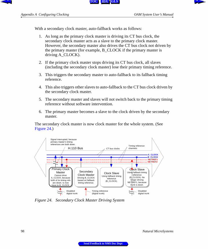
Appendix A Configuring Clocking OAM System User’s Manual
IDX GLSTOC
With a secondary clock master, auto-fallback works as follows:
1. As long as the primary clock master is driving its CT bus clock, the secondary clock master acts as a slave to the primary clock master. However, the secondary master also drives the CT bus clock not driven by the primary master (for example, B_CLOCK if the primary master is driving A_CLOCK).
2. If the primary clock master stops driving its CT bus clock, all slaves (including the secondary clock master) lose their primary timing reference.
3. This triggers the secondary master to auto-fallback to its fallback timing reference.
4. This also triggers other slaves to auto-fallback to the CT bus clock driven by the secondary clock master.
5. The secondary master and slaves will not switch back to the primary timing reference without software intervention.
6. The primary master becomes a slave to the clock driven by the secondary master.
The secondary clock master is now clock master for the whole system. (See Figure 24.)
Figure 24. Secondary Clock Master Driving System
H.110 Bus
A_CLOCKB_CLOCK
Primary ClockMaster
Cannot driveA_CLOCK, becauseboth of its timing refs
are down. Is nowslave to B_CLOCK.
SecondaryClock MasterDriving B_CLOCKbased on fallbacktiming reference.
Clock SlaveUsing fallback timing
reference(B_CLOCK).
Clock SlaveUsing fallback timing
reference(B_CLOCK). Nolonger driving
NETREF1, becausetrunk is down.
Disableddigital trunk
CT bus clocks
Timing reference(digital trunk)
NETREF1NETREF2
Timing referencechannels
Disableddigital trunk
Signal interrupted, becauseprimary master’s timingreferences are both down.
98 Natural MicroSystems
Send Feedback to NMS Doc Dept

OAM System User’s Manual Clock Fallback Procedure
IDX GLSTOC
Clock Fallback Procedure
The diagrams on the following pages illustrate the clock fallback procedures for the primary clock master, secondary clock master, and slave.
The shaded areas in the diagrams below indicate conditions and behaviors which are not strictly defined or described in the ECTF H.110 Hardware Compatibility Specification: CT Bus R1.0 specification.
Note: The diagrams describe the actions taken by most NMS board models in these situations. For specifics on a particular board, refer to the board manual.
Natural MicroSystems 99
Send Feedback to NMS Doc Dept

Appendix A Configuring Clocking OAM System User’s Manual
IDX GLSTOC
Figure 25 illustrates the role of the primary clock master in clock fallback. Note that if the primary master loses its primary timing reference and switches to its secondary reference, and then the primary reference is established again, the master switches back to the primary timing reference.
Figure 25. Clock Fallback Behavior (Primary Clock Master)
Is primaryclock master’s primary
timing referencefunctional?
Start
Yes
Primary clock master drives one ofthe two CT bus clocks (A_CLOCK or
B_CLOCK) based on its primary timingreference. All other boards are slaves to
this clock, including the secondarymaster.
No
Is primary clockmaster’s fallbacktiming reference
functional?
Yes
Primary clock master drives the sameCT bus clock, based on its fallback timingreference. All other boards continue to be
slaves to this clock, including thesecondary master.
Is primaryclock master’s auto-
fallback enabled?Yes
No
No
Primary clock master entersstandalone mode, using its internal
oscillator as its timing reference. It nolonger drives a bus clock. The board stays
in this mode until the clock is reprogrammedby the application. The board may not be
in an operable condition.
Primary clock master continues toattempt to use the bad primary timing
reference. At this point, the board may notbe in an operable condition.
Is secondary clockmaster driving a bus
clock?
No
Yes
Primary clock master becomes aslave to the secondary master. The
board stays in this mode until the clock isreprogrammed by the application or until it
loses the timing reference from thesecondary master..
Typical NMSboard behavior.Not strictly definedin ECTF spec.
100 Natural MicroSystems
Send Feedback to NMS Doc Dept

OAM System User’s Manual Clock Fallback Procedure
IDX GLSTOC
Figure 26 illustrates the role of the secondary clock master in clock fallback. The secondary master takes over only if the primary master loses both of its timing references. The secondary master continues to drive the clock for the whole system until software intervention by an application.
Figure 26. Clock Fallback Procedure (Secondary Clock Master)
Secondary master drivesthe CT bus clock not driven by the primary
master, using its fallback timing reference (e.g.,if primary master drove A_CLOCK, secondary
drives B_CLOCK). All slaves switch to this clock.
Secondary master continues as thesystem master until reset by an
application.
Start
Yes
Issecondary masterreceiving bus clocksignal from primary
master?
No
Is secondaryclock master’s fallback
timing referencefunctional?
Yes
No
Secondary master continues to actas a slave to the primary master. It alsodrives the CT bus clock not driven by theprimary master, based on the clock the
primary master is driving. All slaves usethe primary master signal.
Secondary clock master drives the clock,using its internal oscillator as its timing
reference. The board stays in this mode untilthe clock is reprogrammed by the application.The system is not in an operable condition.
Typical NMSboard behavior.Not strictly definedin ECTF spec.
Natural MicroSystems 101
Send Feedback to NMS Doc Dept
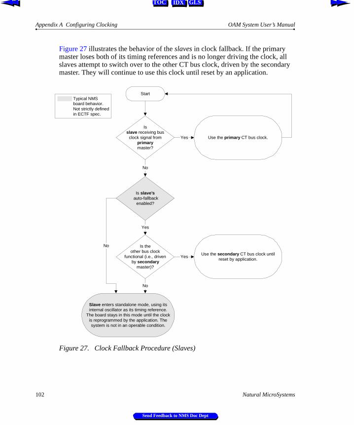
Appendix A Configuring Clocking OAM System User’s Manual
IDX GLSTOC
Figure 27 illustrates the behavior of the slaves in clock fallback. If the primary master loses both of its timing references and is no longer driving the clock, all slaves attempt to switch over to the other CT bus clock, driven by the secondary master. They will continue to use this clock until reset by an application.
Figure 27. Clock Fallback Procedure (Slaves)
Use the secondary CT bus clock untilreset by application.
Start
Yes
Isslave receiving bus
clock signal fromprimarymaster?
No
Is theother bus clock
functional (i.e., drivenby secondary
master)?
Yes
Yes
No
Is slave’s auto-fallback
enabled?
No
Use the primary CT bus clock.
Slave enters standalone mode, using itsinternal oscillator as its timing reference.
The board stays in this mode until the clockis reprogrammed by the application. Thesystem is not in an operable condition.
Typical NMSboard behavior.Not strictly definedin ECTF spec.
102 Natural MicroSystems
Send Feedback to NMS Doc Dept

OAM System User’s Manual Clock Signal Summary
IDX GLSTOC
Clock Signal Summary
The following table summarizes the reference clocks that a clock master can drive:
The following table summarizes the timing references that a clock master can use:
Note: Not all signals are supported by all boards. For details on your board models, refer to your board-specific documentation.
Clock Details
A_CLOCK The set of primary bit clocks (CT8A) and framing signals(CTFrameA). The CT8A signal is a 8 MHz clocking reference for transferring data over the CT bus. The CTFrameA provides a low going pulse signal every 1024 (8 MHz) clock cycles.
B_CLOCK The set of secondary bit clocks (CT8B) and framing signals(CTFrameB). The CT8B signal is a 8 MHz clocking reference for transferring data over the CT bus. The CTFrameB provides a low going pulse signal every 1024 (8 MHz) clock cycles.
TimingReference Details
NETWORK The timing signal from a digital trunk attached to the clock master board. Within the digital trunk interface, an 8 kHz reference is derived from the frequency of the incoming signal. The clock master is frequency-locked to this 8 kHz reference so that the long-term timing of the system matches that of the public telephone network.
Note: No timing signal is available from an analog trunk.
NETREF / NETREF1
The CTNETREF_1 signal. Can be 8 kHz, 1.544 MHz, or 8 MHz, but NMS recommends using only 8 kHz signals for most boards.
NETREF2 (H.110 only) The CTNETREF_2 signal. Can be 8 kHz, 1.544 MHz, or 8 MHz, but NMS recommends using only 8 kHz signals for most boards.
OSC Clock signal derived from an oscillator on the clock master board.
Note: Use this timing reference source only if no network timing references are available.
Natural MicroSystems 103
Send Feedback to NMS Doc Dept

Appendix A Configuring Clocking OAM System User’s Manual
IDX GLSTOC
Configuring Clocking in your System
To configure clocking in your system, specify each board’s role in the board’s managed object, using keywords. The following sections describe how to use board configuration keywords to specify clocking configurations on multiple-board systems.
Note: Not all boards can act as primary or secondary master. For details on your board models, refer to your board-specific documentation.
Configuring the Primary Clock Master
The primary clock master drives a CT bus clock used as the primary timing reference by all other boards connected to the CT bus. Use the following keywords to configure the primary clock master:
Keyword Description
Clocking.HBus.ClockMode Specifies the CT bus clock that the board drives. For the primary clock master, specify:
Æ MASTER_A for A_CLOCK
Æ MASTER_B for B_CLOCK
Clocking.HBus.ClockSource Specifies the primary timing reference for the board. For the primary clock master, set to any of the following:
Æ NETREF to use NETREF (also known as NETREF1 in H.110 parlance)
Æ NETREF2 to use NETREF2 (H.110 only)
Æ NETWORK to derive the timing from the clock pulse on a digital trunk connected to the board
Æ OSC to use the board’s on-board oscillator. Use only when no other source is available.
Clocking.HBus.ClockSourceNetwork If Clocking.HBus.ClockSource is set to NETWORK, specifies the board trunk to derive the primary timing reference from (1 to n, where n is the number of trunks on the board). Trunk numbers are zero-based (for example, specify 1 for trunk 0).
104 Natural MicroSystems
Send Feedback to NMS Doc Dept

OAM System User’s Manual Configuring the Primary Clock Master
IDX GLSTOC
Clocking.HBus.AutoFallBack Enables or disables auto-fallback on the board. When set to YES this keyword specifies that the board automatically switches to the Clocking.HBus.FallBackClockSource timing reference when the Clocking.HBus.ClockSource timing reference fails. The board continues to drive the CT bus clock using this timing reference until the first timing reference is re-established.
Clocking.HBus.FallBackClockSource Specifies the fallback timing reference for the board to use if the primary timing reference fails. The board continues to drive the CT bus clock using this timing reference until the primary timing reference is re-established. For the primary clock master, set to any of the following:
Æ NETREF to use NETREF(1)
Æ NETREF2 to use NETREF2 (H.110 only)
Æ NETWORK to derive the timing from the clock pulse on a digital trunk connected to the board
Æ OSC to use the board’s on-board oscillator. Use only when no other source is available.
The fallback timing reference should be different from the primary timing reference.
Clocking.HBus.FallBackNetwork If Clocking.HBus.FallBackClockSource is set to NETWORK, specifies the board trunk to derive the fallback timing reference from. (1 to n, where n is the number of trunks on the board). Trunk numbers are zero-based (for example, specify 1 for trunk 0).
Keyword Description
Natural MicroSystems 105
Send Feedback to NMS Doc Dept
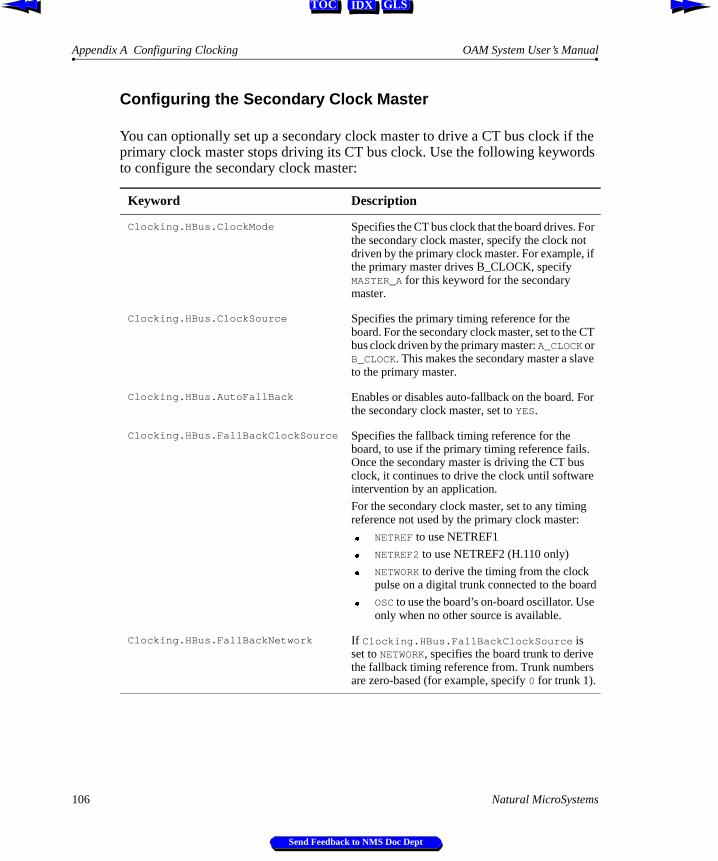
Appendix A Configuring Clocking OAM System User’s Manual
IDX GLSTOC
Configuring the Secondary Clock Master
You can optionally set up a secondary clock master to drive a CT bus clock if the primary clock master stops driving its CT bus clock. Use the following keywords to configure the secondary clock master:
Keyword Description
Clocking.HBus.ClockMode Specifies the CT bus clock that the board drives. For the secondary clock master, specify the clock not driven by the primary clock master. For example, if the primary master drives B_CLOCK, specify MASTER_A for this keyword for the secondary master.
Clocking.HBus.ClockSource Specifies the primary timing reference for the board. For the secondary clock master, set to the CT bus clock driven by the primary master: A_CLOCK or B_CLOCK. This makes the secondary master a slave to the primary master.
Clocking.HBus.AutoFallBack Enables or disables auto-fallback on the board. For the secondary clock master, set to YES.
Clocking.HBus.FallBackClockSource Specifies the fallback timing reference for the board, to use if the primary timing reference fails. Once the secondary master is driving the CT bus clock, it continues to drive the clock until software intervention by an application.
For the secondary clock master, set to any timing reference not used by the primary clock master:
Æ NETREF to use NETREF1
Æ NETREF2 to use NETREF2 (H.110 only)
Æ NETWORK to derive the timing from the clock pulse on a digital trunk connected to the board
Æ OSC to use the board’s on-board oscillator. Use only when no other source is available.
Clocking.HBus.FallBackNetwork If Clocking.HBus.FallBackClockSource is set to NETWORK, specifies the board trunk to derive the fallback timing reference from. Trunk numbers are zero-based (for example, specify 0 for trunk 1).
106 Natural MicroSystems
Send Feedback to NMS Doc Dept

OAM System User’s Manual Configuring Clock Slaves
IDX GLSTOC
Configuring Clock Slaves
Any board connected to the CT bus that is not the primary or secondary clock master should be configured as a clock slave. Each clock slave derives its primary timing reference from A_CLOCK or B_CLOCK (whichever is driven by the primary clock master).
If you have set up a secondary clock master, when the primary clock master stops driving its CT bus clock, the clock slaves can get their clocking information from the secondary clock master.
Use the following keywords to configure clock slaves:
Configuring Standalone BoardsIf you want to configure a board in standalone mode so that the board references its own timing information, set Clocking.HBus.ClockMode to STANDALONE.
In this mode, the board will not be able to make connections to the CT bus.
With some board models, specifying standalone mode causes certain default switch connections to be made on the board to route incoming information from the trunk to DSP resources. For details, see the board documentation.
Keyword Description
Clocking.HBus.ClockMode Specifies the CT bus clock that the board drives. For a clock slave, set to SLAVE to indicate that the board does not drive any CT bus clock.
Clocking.HBus.ClockSource Specifies the primary timing reference for the board. For each slave, set to the CT bus clock driven by the primary master: A_CLOCK or B_CLOCK.
Clocking.HBus.AutoFallBack Enables or disables auto-fallback on the board. If you have set up a secondary clock master, set to YES for each slave. Otherwise, set to NO.
Clocking.HBus.FallBackClockSource Specifies the fallback timing reference for the board, to use if the primary timing reference fails. If you have set up a secondary clock master, set to the timing reference driven by the secondary clock master. Once a slave switches to the secondary clock, it continues to use the clock until reset by an application.
Natural MicroSystems 107
Send Feedback to NMS Doc Dept
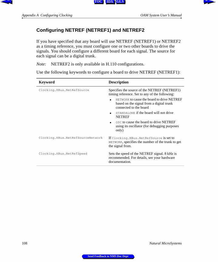
Appendix A Configuring Clocking OAM System User’s Manual
IDX GLSTOC
Configuring NETREF (NETREF1) and NETREF2
If you have specified that any board will use NETREF (NETREF1) or NETREF2 as a timing reference, you must configure one or two other boards to drive the signals. You should configure a different board for each signal. The source for each signal can be a digital trunk.
Note: NETREF2 is only available in H.110 configurations.
Use the following keywords to configure a board to drive NETREF (NETREF1):
Keyword Description
Clocking.HBus.NetRefSource Specifies the source of the NETREF (NETREF1) timing reference. Set to any of the following:
Æ NETWORK to cause the board to drive NETREF based on the signal from a digital trunk connected to the board
Æ STANDALONE if the board will not drive NETREF
Æ OSC to cause the board to drive NETREF using its oscillator (for debugging purposes only)
Clocking.HBus.NetRefSourceNetwork If Clocking.HBus.NetRefSource is set to NETWORK, specifies the number of the trunk to get the signal from.
Clocking.HBus.NetRefSpeed Sets the speed of the NETREF signal. 8 kHz is recommended. For details, see your hardware documentation.
108 Natural MicroSystems
Send Feedback to NMS Doc Dept

OAM System User’s Manual Configuring NETREF (NETREF1) and NETREF2
IDX GLSTOC
Use the following keywords to configure a board to drive NETREF2:
Note: Not all boards can drive NETREF or NETREF2. For details on your board models, refer to your board-specific documentation.
Keyword Description
Clocking.HBus.NetRef2Source Specifies the source of the NETREF2 timing reference. Set to any of the following:
Æ OSC to cause the board to drive NETREF2 using its oscillator
Æ NETWORK to cause the board to drive NETREF2 based on the signal from a digital trunk connected to the board
Æ STANDALONE if the board will not drive NETREF2.
Clocking.HBus.NetRef2SourceNetwork If Clocking.HBus.NetRefSource is set to NETWORK, specifies the number of the trunk to get the signal from.
Clocking.HBus.NetRef2Speed Sets the speed of the NETREF2 signal. 8 kHz is recommended. For details, see your hardware documentation.
Natural MicroSystems 109
Send Feedback to NMS Doc Dept

Appendix A Configuring Clocking OAM System User’s Manual
IDX GLSTOC
Example: Multi-Board System
The following example describes a system configuration (illustrated in Figure 28), where four boards reside in a single chassis. The boards are configured in the following way:
Auto-fallback is enabled on all boards. Board A, defined as the primary clock master, drives A_CLOCK. All other boards on the system connected to the CT bus use A_CLOCK as their primary timing reference. Board A derives its own timing reference from the NETREF signal driven by board D, based on a signal from one of board D’s digital trunks (trunk 4).
In addition, board A is configured to use timing signals received on one of its own digital trunks (trunk 2) as its fallback timing reference. If NETREF fails, board A continues to drive A_CLOCK based on its fallback timing reference.
Board B is set up as a backup, or secondary clock master, driving the CT bus clock not driven by the primary clock master. Board B normally receives its timing reference from A_CLOCK, which is driven by board A. This means that board B acts as a clock slave to board A. If A_CLOCK fails, board B continues driving B_CLOCK, but now uses the timing signals received from one of its digital trunks (trunk 3). All other slave boards fall back to B_CLOCK, and board B serves as the clock master. The primary master also falls back to B_CLOCK, and is now a slave to the secondary master. The system continues in this configuration until software intervention by the application.
Board Description DrivesPrimary timing reference
Fallback timing reference
A Primary clock master A_CLOCK NETREF Local digital trunk 2
B Secondary clock master B_CLOCK A_CLOCK Local digital trunk 3
C Clock slave Nothing A_CLOCK B_CLOCK
D Clock slave NETREF based on local digital trunk 4
A_CLOCK B_CLOCK
110 Natural MicroSystems
Send Feedback to NMS Doc Dept

OAM System User’s Manual Example: Multi-Board System
IDX GLSTOC
This configuration assigns the following clocking priorities:
Figure 28. Sample Board Clocking Configuration
Timing Priority Clocking Configuration
First Board A (primary master) drives A_CLOCK using its primary timing reference (board D, digital trunk 4, via NETREF). Slaves sync to A_CLOCK.
Second Board A (primary master) drives A_CLOCK using its fallback timing reference (board A, digital trunk 2). Slaves sync to A_CLOCK.
Third Board B (secondary master) drives B_CLOCK using its fallback timing reference (board B, digital trunk 3). Slaves sync to B_CLOCK.
H.110 BusA_CLOCK
B_CLOCK
NETREF
Board CClock Slave
Board BSecondary
Clock Master(Network board)
Board DClock Slave
(Network board)
Drives A_CLOCK. UsesNETREF as timingreference. Falls back tonetwork signal.
Drives B_CLOCK.Uses A_CLOCK astiming reference. Fallsback to network signal.
Does not drive a clock.Uses A_CLOCK astiming reference. Fallsback to B_CLOCK.
Drives NETREF based onnetwork signal. Uses A_CLOCKas timing reference. Falls backto B_CLOCK.
Clock source
Driving clock
Fallback clock source
A_CLOCK
B_CLOCK
NETREF
Board APrimary Clock
Master(Network board)
NETREF2NETREF2
Network(trunk
connection)
Network(trunk
connection)
Network(trunk
connection)
Natural MicroSystems 111
Send Feedback to NMS Doc Dept

Appendix A Configuring Clocking OAM System User’s Manual
IDX GLSTOC
Clock configuration keywords are set as follows for each board:
Board Role Clocking Keyword Settings
A Primary clock master Clocking.HBus.ClockMode = MASTER_AClocking.HBus.ClockSource = NETREFClocking.HBus.AutoFallBack = YESClocking.HBus.FallBackClockSource = NETWORKClocking.HBus.FallBackNetwork = 2
B Secondary clock master Clocking.HBus.ClockMode = MASTER_BClocking.HBus.ClockSource = A_CLOCKClocking.HBus.AutoFallBack = YESClocking.HBus.FallBackClockSource = NETWORKClocking.HBus.FallBackNetwork = 3
C Clock slave Clocking.HBus.ClockMode = SLAVEClocking.HBus.ClockSource = A_CLOCKClocking.HBus.AutoFallBack = YESClocking.HBus.FallBackClockSource = B_CLOCK
D Slave driving NETREF Clocking.HBus.ClockMode = SLAVEClocking.HBus.ClockSource = A_CLOCKClocking.HBus.AutoFallBack = YESClocking.HBus.FallBackClockSource = B_CLOCKClocking.HBus.NetRefSource = NETWORKClocking.HBus.NetRefSourceNetwork = 4Clocking.HBus.NetRefSpeed = 8K
112 Natural MicroSystems
Send Feedback to NMS Doc Dept
IDX GLSTOC
Appendix B
Migration
Introduction 114
Summary of Changes 114
agmon vs. OAM 115OAM Service Utilities 116
Configuration Files 116ag2oam 117
Board Identification 118
Hot Swap Changes 119
Natural MicroSystems 113
Send Feedback to NMS Doc Dept

Appendix B Migration OAM System User’s Manual
IDX GLSTOC
Introduction
This appendix discusses migration from agmon to OAM.
Summary of Changes
OAM was introduced with CT Access 4.0. This section summarizes the changes incurred with the introduction of OAM:
Æ The AG board configuration and monitoring utility, agmon, is deprecated. OAM now performs board management operations across all boards, including AG, QX, CX and CG models. Utilities included with OAM duplicate and enhance operations formerly performed by agmon.
Æ The AGM library is deprecated. OAM has a full-featured API for initializing and monitoring boards, and for performing many other tasks.
Æ The AG configuration file has been replaced by files with very different structure and syntax. Keywords used in these files are very different from AG configuration file keywords.
The ag2oam utility included with OAM translates AG configuration files into the new syntax.
Æ Previously, the only method of identifying a board in software was the board number. A new identifier, the name, can now also be used to identify each board, as well as certain software modules and other components.
Æ The HSI service is deprecated. Hot Swap functionality is implemented as an extended component of OAM. Note that the Hot Swap Manager has not changed.
Æ The QX board configuration and monitoring utility, qxload, is deprecated. OAM now performs board management operations for QX boards. For information about migrating QX applications to OAM, refer to the QX 2000 Installation and Developer’s Manual.
Æ NMS SNMP services now use OAM services. Therefore, SNMP can only provide information on boards started using the OAM service.
114 Natural MicroSystems
Send Feedback to NMS Doc Dept

OAM System User’s Manual agmon vs. OAM
IDX GLSTOC
agmon vs. OAM
agmon is deprecated as of Natural Access 2000-1. A new CT Access service, OAM, provides all functionality formerly provided by agmon. OAM differs from agmon in the following major ways:
Æ agmon is a utility program, controllable only using its command line. OAM is a bona fide CT Access service, accessible programmatically using its extensive API. Various subsets of OAM service functionality can also be accessed with the oamsys, oamcfg, and oammon utilities.
Æ agmon configures, boots, and then monitors boards, as a single operation. With OAM, configuration, board starting/stopping, and monitoring operations are all accessible separately, using the OAM utilities and API functions.
Æ With agmon, the central repository of configuration information is the AG configuration file. With OAM, configuration information is kept in a dynamic database, managed by the service. The configuration information for a given board is called the managed object for the board.
The utilities supplied with OAM use configuration files as a convenient way to supply information to the OAM database. However, when OAM starts (boots) boards, the information in the managed object for each board (not the configuration files) determines how the board will be configured.
Æ OAM provides functionality not available with agmon, such as board testing (for board models that support this operation) and alert notification. It is also extensible with extended management components (EMCs) and board plug-ins. For example, Hot Swap is now implemented as an EMC.
Æ OAM supports new board families, such as CG.
Æ OAM and agmon cannot be used simultaneously.
Natural MicroSystems 115
Send Feedback to NMS Doc Dept
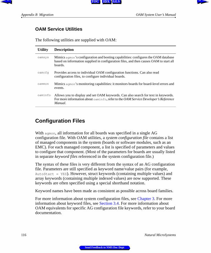
Appendix B Migration OAM System User’s Manual
IDX GLSTOC
OAM Service Utilities
The following utilities are supplied with OAM:
Configuration Files
With agmon, all information for all boards was specified in a single AG configuration file. With OAM utilities, a system configuration file contains a list of managed components in the system (boards or software modules, such as an EMC). For each managed component, a list is specified of parameters and values to configure that component. (Most of the parameters for boards are usually listed in separate keyword files referenced in the system configuration file.)
The syntax of these files is very different from the syntax of an AG configuration file. Parameters are still specified as keyword name/value pairs (for example, AutoStart = YES). However, struct keywords (containing multiple values) and array keywords (containing multiple indexed values) are now supported. These keywords are often specified using a special shorthand notation.
Keyword names have been made as consistent as possible across board families.
For more information about system configuration files, see Chapter 3. For more information about keyword files, see Section 3.4. For more information about OAM equivalents for specific AG configuration file keywords, refer to your board documentation.
Utility Description
oamsys Mimics agmon’s configuration and booting capabilities: configures the OAM database based on information supplied in configuration files, and then causes OAM to start all boards.
oamcfg Provides access to individual OAM configuration functions. Can also read configuration files, to configure individual boards.
oammon Mimics agmon’s monitoring capabilities: it monitors boards for board-level errors and events.
oaminfo Allows you to display and set OAM keywords. Can also search for text in keywords. For more information about oaminfo, refer to the OAM Service Developer’s Reference Manual.
116 Natural MicroSystems
Send Feedback to NMS Doc Dept

OAM System User’s Manual ag2oam
IDX GLSTOC
ag2oam
Included with the OAM software is a utility, ag2oam, which translates AG configuration files into system configuration files and keyword files which oamsys can process. To use ag2oam:
1. Go through the AG configuration file, and determine the product type for each board number. For example, Board 0 = AG Quad T1; Board 1 = AG Quad T1; Board 2 = AG 4000C T1.
2. Enter: ag2oam [options]
where options are:
For example, with the configuration listed in step 1 above, you would enter:
ag2oam -f myfile.cfg -p0..1=AG_Quad_T1 -p2=AG_4000C_T1
Option Description
-c Causes ag2oam to duplicate in the output files any comments it finds in the original file. If this option is not specified, comment lines are omitted.
-f filename Name (and path, if necessary) of AG configuration file to translate. Default is ag.cfg.
If no path is specified, ag2oam searches first in the current directory, and then in the paths specified with the AGLOAD environment variable.
-p[m[..n]=] product AG product type for board(s) m...n. This option can appear on the command line as many times as necessary. If you do not specify board numbers, the specified product types used for all boards.
Section 6.3.1 describes how to get a list of valid values for product.
Note: ISA boards are not supported, since they are not supported by OAM.
-? Causes ag2oam to display its help screen, and terminate.
-h Causes ag2oam to display its help screen, and terminate.
Natural MicroSystems 117
Send Feedback to NMS Doc Dept
Appendix B Migration OAM System User’s Manual
IDX GLSTOC
If the operation is successful, ag2oam returns without a message. ag2oam outputs the following files, in the same path as the source file:
Æ A system configuration file, listing all boards from your AG configuration file. This file is named oldname_oamsys.cfg, where oldname is the name of your AG configuration file, minus the extension. For example: myfile_oamsys.cfg
Æ One or more keyword files, one for each board listed in your AG configuration file. This file is named oldname_Board_n.cfg, where oldname is the name of your AG configuration file, minus the extension, and n is the number of the board as it appeared in your AG configuration file. For example: myfile_Board_0.cfg
The keyword file for each board is appropriately referenced in the system configuration file, in the section describing the board.
Note: ag2oam assumes that the input AG configuration file is valid. If errors exist in the input file, in most cases they will be propagated in the output files.
Board Identification
Previously, the board number was the only way of identifying a board in software. This number was assigned in the AG configuration file. With the OAM service, boards are also identified by board names. The board name for a board is assigned when the managed object is first created in the OAM database for the board. You can specify the name of a board in the system configuration file you supply to oamsys (see Chapter 3).
Names are also used for other types of managed objects, such as extended management components (EMCs), board plug-ins, and the OAM Supervisor itself. For details, see Chapter 1.
Most NMS API software still requires board numbers. Within OAM, boards are still assigned unique board numbers, and you can still use this method to identify them in software. Within the OAM service, you can also identify a board using its location (bus and slot), as well as with other information. For details, see Section 1.4.2.
118 Natural MicroSystems
Send Feedback to NMS Doc Dept

OAM System User’s Manual Hot Swap Changes
IDX GLSTOC
Hot Swap Changes
Previously, the Hot Swap interface to CT Access was implemented as a CT Access service (the HSI service). This interface is now implemented as an OAM extended management component (EMC). Changes to the API made as a result of the OAM implementation are listed below. For details, refer to the OAM Service Developer’s Reference Manual.
Æ The HSI service is now deprecated, and is not compatible with OAM.
Æ The information formerly returned by HSI functions hsiGetBoardInfo and hsiGetLogicalBoardInfo is now available using other means, as follows:
Æ Hot Swap events are now passed to applications using the same event handling mechanism used for OAM events. Hot Swap events and errors have not changed, except for their prefixes: Hot Swap events now have the prefix HSWEVN_, and Hot Swap error codes now have the prefix HSWERR_. They are specified in hswdef.h.
Æ Hot Swap state names have changed, to be closer to their SNMP equivalents:
Information New Source
Board information
oamBoardGetXXX and oamBoardLookupByXXX functions
Hot Swap state Board.name.State keyword in the Hot Swap EMC managed object
Old State Name New State Name
NOT PRESENT Extracted
OFFLINE OffLine
PREPARATION OnLinePending
PREPARATION FAILED Failed
RUNNING OnLine
DOWNING OffLinePending
(none -- see below) Unsupported
Natural MicroSystems 119
Send Feedback to NMS Doc Dept

Appendix B Migration OAM System User’s Manual
IDX GLSTOC
Æ A new state has been added to the state machine: Unsupported. If a board does not support Hot Swap, it is permanently in this state.
Æ The Hot Swap Developer’s Manual is now obsolete. Hot Swap runtime information is documented in the manual you are currently reading. Hot Swap developer information is in the OAM Service Developer’s Reference Manual.
120 Natural MicroSystems
Send Feedback to NMS Doc Dept

IDX GLSTOC
Index
AA_CLOCK
described 91summary 103
ag2oam utility 117–118AGLOAD 17AGM library 114agmon utility
and config files 31, 35compared to OAM 115
array keywordsdescribed 38–40determining no. of elements in 39expansion 39–40
auto-fallback. See fallback
BB_CLOCK
described 91summary 103
biostest utility 73using 23, 26, 71–73
blocate utility 74board name
assigning in config file 32changing 59default 62defined 13retrieving 57
board numberchanging 59default 62defined 13migration 118retrieving 57specifying in sys config file 32
board plug-in. See plug-ins
Natural MicroSystems
Send Feedback to NMS
board product typedisplaying types using oamcfg 55specifying in sys config file 32
boardschanging identification info 59clocking 90–112clocking. See clockingidentification methods 13monitoring 66–67retrieving identification info 57specifying in config files 32stand-alone 107starting (booting) 60stopping (shutting down) 60testing 61
bus clock. See clocking
CClock Management
EMC 10, 28fallback. See fallbackinstalled service 17managed object name 33
clock slavesconfiguring 107described 91–92
clockingconfiguration 104–112overview 90–103timing references 93–96
configuration database 12configuration files
keyword. See keyword filesmigrating to OAM 116–118overview 30system. See system configuration files
connections, switch 86CT Access server. See ctdaemon
121
Doc Dept

Index OAM System User’s Manual
IDX GLSTOC
ctdaemondefined 10starting 44
Ddriver board ID 13driver name 13driver, Hot Swap. See Hot Swap driver
EEMC
Clock Management. See Clock Managementdefined 10Hot Swap. See Hot Swapmanaged object names 33
environment variables 17extended management component. See EMC
Ffallback timing reference
configuring for clock slave 107configuring for primary master 105configuring for secondary master 106described 96
file, readme 17
HH.100/H.110 clocking. See clockingHot Swap
configuring bus address space 23–26Control/ Status Register 20determining if a chassis supports 23, 71driver. See Hot Swap driverEMC 10, 21–22keywords 37LED 20, 85managed object name 33Manager. See Hot Swap Managermigrating to OAM. See migrationoverview 20–22platform requirements 22setting up 23–26verifying 45
122
Send Feedb
Hot Swap driver 85starting 42–44utility 81–83
Hot Swap LED 20Hot Swap Manager
installed service 17monitoring 79–80starting 42–44, 75–78starting in console mode 76
HS_CSR 20HSI service 114, 119hsiGetBoardInfo 119hsiGetLogicalBoardInfo 119hsmgr utility 75–77hsmon utility
description and usage 79–80using to verify Hot Swap 45
hssrvr utility 81–83
IID, driver board 13interface, PCI 20
Kkeyword files
comments in 35continuation lines 35creating 35–37described 30sample 36sample files 30, 35syntax 35using with oamcfg 57
keywords 37–40array 38–40clocking 104–109described 13determining valid keywords for object 37file. See keyword filesHot Swap 37migration to OAM 116name/value pairs 37specifying with oamcfg 57–58struct 37–38Supervisor 37
Natural MicroSystems
ack to NMS Doc Dept
OAM System User’s Manual Index
IDX GLSTOC
LLD_LIBRARY_PATH 17LED
Hot Swap 85identifying board with 74
library, AGM 114
Mmanaged components 8managed objects
and configuration database 12creating for boards 55–56defined 11deleting 56specifying configurations for 33
migration 114–120agmon vs. OAM 115board identification 118Hot Swap changes 119–120migrating configuration files 116–118summary of changes 114
monitoring, trunk 87
NNETREF
configuring 108–109described 94–95summary 103
NETREF2configuring 108–109described 95summary 103
NETWORK timing referencedescribed 93summary 103
Natural MicroSystems
Send Feedback to NMS
OOAM
accessing 14–16API 16board ID methods 13components 9–10defined 8environment variables 17installing 17migrating to. See migrationoverview 8Supervisor. See Supervisorsystem configuration summary 18utilities 14–16
OAM Service API 16OAM Supervisor. See Supervisoroamcfg utility 52–63
changing board ID info with 59changing keyword settings with 57–58command-line options 53–55creating board managed objects with 55deleting board managed objects with 56described 15, 52displaying board ID info with 57displaying board product types with 55launching 52multi-operation invocations 61order of operation 62–63replacing existing data 59starting boards with 60stopping boards with 60testing boards with 61
oaminfo utility 16oammon utility
described 16using 66–67
oamsys utility 48–49and oamcfg 48and system configuration files 30described 15, 48launching 48
OSCdescribed 94summary 103
123
Doc Dept

Index OAM System User’s Manual
IDX GLSTOC
PPCI bus
and slot, as board identification method 13and slot, changing for a board 59and slot, default 62and slot, determining for boards 84and slot, retrieving for a board 57and slot, specifying for a board 32determining locations 27, 74segments and space windows 23–24using leftover allocated space 24–26
PCI interface 20pciscan utility 27, 84plug-ins
defined 10managed object names 33
primary clock masterconfiguring 104–105described 91–92
primary timing referenceconfiguring for clock slave 107configuring for primary master 104configuring for secondary master 106
Qqxload 114
Rreadme file 17
Ssecondary clock master
configuring 106described 97–98
serial number 13services
HSI 114, 119OAM 17registered for OAM 17
showcx95 utility 86SNMP 114struct keywords 37–38
124
Send Feedb
Supervisordescribed 9keywords 37managed object 12managed object name 33
switch connections 86system configuration files
comments in 31creating 31–34described 30example 34mandatory statements 32sample files 31specifying boards in 32specifying configs for non-board objects in 33specifying keyword files in 32–33specifying keywords directly in 33syntax 31using with oamsys 48
Ttiming references
configuring 104–109described 93–96
trunk monitoring 87trunkmon utility 87–88
Uutilities
ag2oam 117–118biostest 23, 73blocate 74hsmgr 75–77hsmon 45, 79–80hssrvr 81–83list of 116oamcfg 52, 63oammon 66–67oamsys 48–49pciscan 27, 84showcx95 86trunkmon 87–88
Natural MicroSystems
ack to NMS Doc Dept

OAM System User’s Manual Index
IDX GLSTOC
Vvariables, environment 17
Natural MicroSystems
Send Feedback to NMS
125
Doc Dept

Index OAM System User’s Manual
IDX GLSTOC
126 Natural MicroSystems
Send Feedback to NMS Doc Dept