Embed Size (px)
Citation preview

OPERATING INSTRUCTIONS
OAKTON® 35607-00
CON 10Basic Conductivity/TDS Meter
Printed in Singapore 08/00 R2
TDS/Conductivity/°C meterCON 10 Series
HOLD MODE
ONOFF
CALMEAS
ENTERRANGE
C
MEAS
µ s
CONDATC

Table of Contents
1. Introduction ............................................................................................3
2. Display and Keypad Functions ............................................................ 4-52.1 LCD display ...........................................................................................................................42.2 Keypad....................................................................................................................................5
3. Preparation ..........................................................................................6-93.1 Inserting the batteries...........................................................................................................63.2 Connecting the probe and temperature sensor ................................................................73.3 Attaching the probe holder to the meter ...........................................................................83.4 Inserting the probe into the probe holder .........................................................................83.5 Connecting the AC adapter.................................................................................................9
4. Calibration........................................................................................10-134.1 Preparing for calibration....................................................................................................104.2 Calibrating for Conductivity .............................................................................................114.3 Calibrating for TDS .......................................................................................................12-13
5. Temperature Calibration.......................................................................145.1 One-point temperature compensation.............................................................................14
6. Measurement....................................................................................15-166.1 Range Selection ...................................................................................................................156.2 Measurement using Automatic Temperature Compensation ......................................156.3 Measurement using Manual Temperature Compensation...........................................16
7. HOLD......................................................................................................17
8. Probe Care and Maintenance................................................................18
9. Probe Replacement ...............................................................................199.1 Zero calibration ...................................................................................................................199.1 Two point temperature calibration...................................................................................20
10. Troubleshooting ..................................................................................21
11. Error Messages ....................................................................................22
12. Specifications ......................................................................................23
13. Accessories...........................................................................................24
14. Addendum 1: Conductivity to TDS Conversion Factors......................25
15. Addendum 2: Calculating TDS Conversion Factors ............................26
16. Warranty .............................................................................................28
17. Return of Items ...................................................................................28
3
TDS/Conductivity/°C meterCON 10 Series
HOLD MODE
ONOFF
CALMEAS
ENTERRANGE
C
MEAS
µ s
CONDATC
1. Introduction
Thank you for selecting the Oakton® 35607-00 conductivity/TDS meter. Includedwith your meter is an epoxy-body stainless steel probe with built-in temperaturesensor and cable, a built-in four position probe attachment and a built-in meterstand.
Your meter includes electrode holders and batteries.
Please read this manual thoroughly before operating your meter.
4
2. Display and Keypad Functions
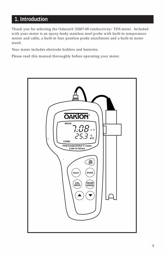
DisplayThe LCD has a primary and secondary display.
• The primary display shows the measured Conductivity or TDS reading. • The secondary display shows the temperature of the reading in °C.
The display also shows error messages, keypad functions and program functions.
C
ppmt
ATC
READY
AUTO
COND
CALMEAS
µmS
Temp
HOLD
ERRONOFF
TDS
2.1
Primary display
Secondary display
MEASurementmode indicator
READYindicator
HOLDindicator
Auto-Rangingindicator
ERRorindicator
Low batteryindicator
Conductivityor TDS modeindicator
ppm or pptindicator
µS or mSindicator
Temperaturecalibrationmode indicator
AutomaticTemperatureCompensationindicator
°C indicator
MEMory indicator
5
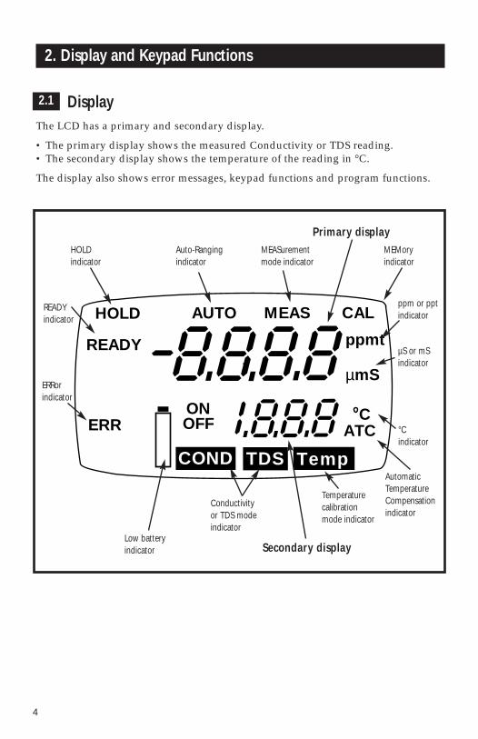
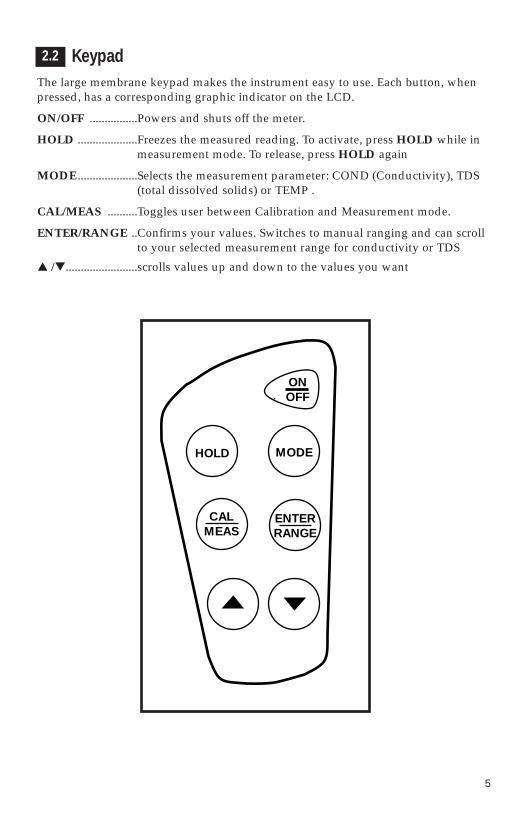
KeypadThe large membrane keypad makes the instrument easy to use. Each button, whenpressed, has a corresponding graphic indicator on the LCD.
ON/OFF ................Powers and shuts off the meter.
HOLD ....................Freezes the measured reading. To activate, press HOLD while inmeasurement mode. To release, press HOLD again
MODE ....................Selects the measurement parameter: COND (Conductivity), TDS(total dissolved solids) or TEMP .
CAL/MEAS ..........Toggles user between Calibration and Measurement mode.
ENTER/RANGE ..Confirms your values. Switches to manual ranging and can scrollto your selected measurement range for conductivity or TDS
▲ /▼........................scrolls values up and down to the values you want
2.2
HOLD MODE
ONOFF
CALMEAS
ENTERRANGE

6
3. Preparation
Inserting the BatteriesFour AAA batteries are included with your meter.
1. Use a Phillips screwdriver to remove the two screws holding the battery cover.See Figure below.
2. Lift meter stand to expose battery cover. Remove battery cover.
3. Insert batteries. Follow the diagram inside the cover for correct polarity.
4. Replace the battery cover into its original position using the two screws removed earlier.
3.1
Battery compartment
Remove thesetwo screws toaccess batterycompartment
7
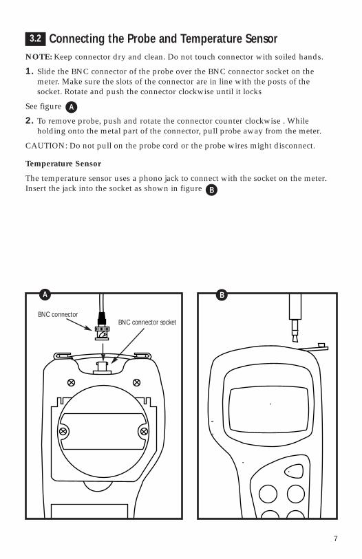
Connecting the Probe and Temperature SensorNOTE: Keep connector dry and clean. Do not touch connector with soiled hands.
1. Slide the BNC connector of the probe over the BNC connector socket on themeter. Make sure the slots of the connector are in line with the posts of the socket. Rotate and push the connector clockwise until it locks
See figure
2. To remove probe, push and rotate the connector counter clockwise . While holding onto the metal part of the connector, pull probe away from the meter.
CAUTION: Do not pull on the probe cord or the probe wires might disconnect.
Temperature Sensor
The temperature sensor uses a phono jack to connect with the socket on the meter.Insert the jack into the socket as shown in figure
3.2
BNC connector socket BNC connector
A
B
A
B
8
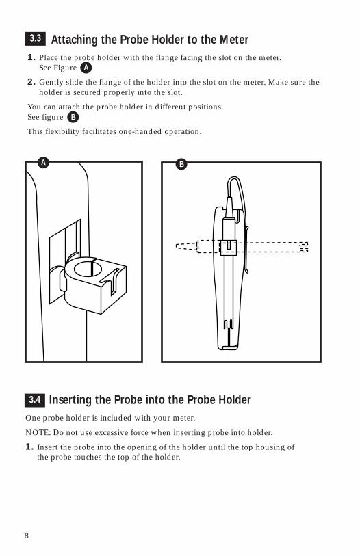
3.3 Attaching the Probe Holder to the Meter1. Place the probe holder with the flange facing the slot on the meter.
See Figure
2. Gently slide the flange of the holder into the slot on the meter. Make sure theholder is secured properly into the slot.
You can attach the probe holder in different positions. See figure
This flexibility facilitates one-handed operation.
Inserting the Probe into the Probe HolderOne probe holder is included with your meter.
NOTE: Do not use excessive force when inserting probe into holder.
1. Insert the probe into the opening of the holder until the top housing of the probe touches the top of the holder.
B
A
BA
3.4

9
Connecting the AC Adapter The AC adapter is not included with your meter; order separately on page 24.
1. Insert the AC jack as shown in figure below.
2. Switch off the meter before plugging the adapter into the power source. This safety precaution protects the software in your meter.
3. Press the ON/OFF button to switch meter on.
D
D
3.5

10
4. Conductivity/TDS Calibration
Preparing for calibration
Selecting a calibration standard
For best results, select a conductivity or TDS standard near the sample value you aremeasuring. Alternatively, use a calibration solution value that is approximately 2/3 thefull scale (F.S.) value of the measurement range you plan to use. For example, in the 0to 1999 µS range, use a 1413 µS solution for calibration.
Calibrating the meter in conductivity range(s) also calibrates the corresponding TDSrange. A calibration value in the TDS mode of a particular range replaces a prior cali-bration value in the corresponding conductivity mode if both fall in the same range,and vice versa. The following table lists the corresponding ranges:
You only need one calibration for measurement of the entire range of the meter. If arange is not calibrated, the meter automatically detects the closest range calibrated anduses that calibration information. However, only the ranges that have been calibratedhave maximum accuracy.
When to calibrate
If you are measuring in solutions with conductivity lower than 100 µS, or TDS lowerthan 50 ppm, calibrate the meter at least once a week to get specified ±1% F.S. accuracy.If you are measuring in the mid ranges, calibrate the meter at least once a month. If youmake measurements at extreme temperatures, calibrate at least once a week.
4.1
Conductivity range TDS range
0.00 to 19.99 µS 0.00 to 9.99 ppm0.0 to 199.9 µS 10.0 to 99.9 ppm
0 to 1999 µS 100 to 999 ppm0.00 to 19.99 mS 1.00 to 9.99 ppt
11
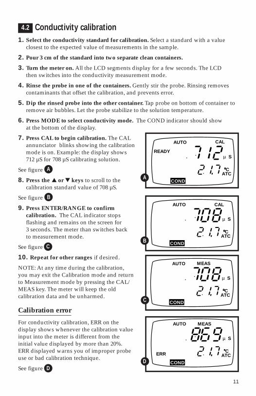
Conductivity calibration1. Select the conductivity standard for calibration. Select a standard with a value
closest to the expected value of measurements in the sample.
2. Pour 3 cm of the standard into two separate clean containers.
3. Turn the meter on. All the LCD segments display for a few seconds. The LCD then switches into the conductivity measurement mode.
4. Rinse the probe in one of the containers. Gently stir the probe. Rinsing removescontaminants that offset the calibration, and prevents error.
5. Dip the rinsed probe into the other container. Tap probe on bottom of container toremove air bubbles. Let the probe stabilize to the solution temperature.
6. Press MODE to select conductivity mode. The COND indicator should show at the bottom of the display.
7. Press CAL to begin calibration. The CALannunciator blinks showing the calibrationmode is on. Example: the display shows 712 µS for 708 µS calibrating solution.
See figure
8. Press the ▲ or ▼ keys to scroll to the calibration standard value of 708 µS.
See figure
9. Press ENTER/RANGE to confirm calibration. The CAL indicator stops flashing and remains on the screen for 3 seconds. The meter than switches back to measurement mode.
See figure
10. Repeat for other ranges if desired.
NOTE: At any time during the calibration, you may exit the Calibration mode and return to Measurement mode by pressing the CAL/MEAS key. The meter will keep the old calibration data and be unharmed.
Calibration error
For conductivity calibration, ERR on the display shows whenever the calibration valueinput into the meter is different from the initial value displayed by more than 20%. ERR displayed warns you of improper probe use or bad calibration technique.
See figure
B
C
µ S
ATC
AUTO CAL
COND
4.2
B
MEAS
C
µ S
ATC
AUTO
CONDC
C
µ S
ATCERR
AUTO MEAS
CONDDD
C
C
µ S
ATC
READY
AUTO
COND
CAL
AA
12
TDS calibration
Option 1: TDS calibration using TDS standards
1. Select the TDS standard for calibration. Our OAKTON calibration solutions have TDS values on the labels. For conversion factors other than those listed, see Addenda 1 and 2, pages 25-26.
2. Pour 3 cm of the standard into two separate clean containers.
3. Turn the meter on. All the LCD segments display for a few seconds. The LCD thenswitches into the conductivity measurement mode.
4. Rinse the probe in one of the containers. Gently stir the probe. Rinsing removescontaminants that offset the calibration, and prevents error.
5. Dip the rinsed probe into the other container. Tap probe on bottom of container toremove air bubbles. Let the probe stabilize to the solution temperature.
6. Press MODE to select TDS mode. The TDS indicator should show at the bottom of the display.
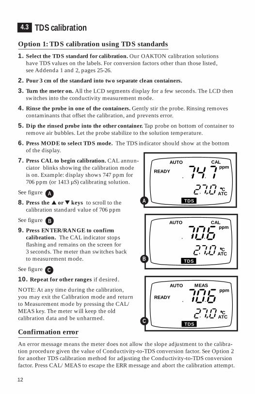
7. Press CAL to begin calibration. CAL annun-ciator blinks showing the calibration mode is on. Example: display shows 747 ppm for706 ppm (or 1413 µS) calibrating solution.
See figure
8. Press the ▲ or ▼ keys to scroll to the calibration standard value of 706 ppm
See figure
9. Press ENTER/RANGE to confirm calibration. The CAL indicator stops flashing and remains on the screen for 3 seconds. The meter than switches back to measurement mode.
See figure
10. Repeat for other ranges if desired.
NOTE: At any time during the calibration, you may exit the Calibration mode and return to Measurement mode by pressing the CAL/MEAS key. The meter will keep the old calibration data and be unharmed.
Confirmation error
An error message means the meter does not allow the slope adjustment to the calibra-tion procedure given the value of Conductivity-to-TDS conversion factor. See Option 2for another TDS calibration method for adjusting the Conductivity-to-TDS conversionfactor. Press CAL/MEAS to escape the ERR message and abort the calibration attempt.
4.3
C
ppm
ATC
AUTO CAL
TDSB
READY
MEAS
C
ppm
ATC
AUTO
TDSC
C
ppm
ATC
READY
AUTO
TDS
CAL
A
B
C
A
13
Option 2: TDS calibration using conversion factors
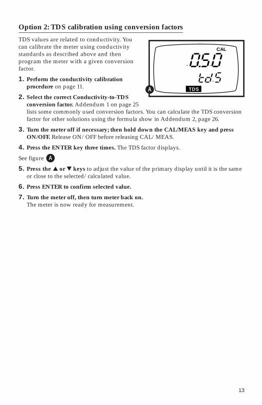
TDS values are related to conductivity. You can calibrate the meter using conductivity standards as described above and then program the meter with a given conversion factor.
1. Perform the conductivity calibration procedure on page 11.
2. Select the correct Conductivity-to-TDS conversion factor. Addendum 1 on page 25 lists some commonly used conversion factors. You can calculate the TDS conversionfactor for other solutions using the formula show in Addendum 2, page 26.
3. Turn the meter off if necessary; then hold down the CAL/MEAS key and pressON/OFF. Release ON/OFF before releasing CAL/MEAS.
4. Press the ENTER key three times. The TDS factor displays.
See figure
5. Press the ▲ or ▼ keys to adjust the value of the primary display until it is the same or close to the selected/calculated value.
6. Press ENTER to confirm selected value.
7. Turn the meter off, then turn meter back on. The meter is now ready for measurement.
TDS
CAL
A
A
14
5. Temperature Calibration
The built-in temperature sensor included in the probe is factory calibrated. Overtime, the temperature sensor response may vary. If you suspect temperature errors,calibrate your sensor using the following one-point calibration procedure.
If you purchase a replacement probe, you must complete a two-point temperaturecalibration. See section 8, Probe Replacement, for details (pages 19-20).
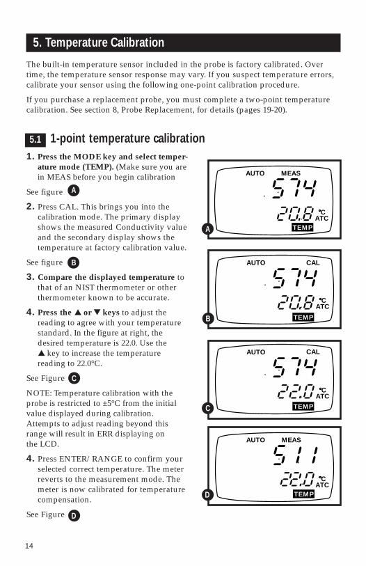
1-point temperature calibration1. Press the MODE key and select temper-
ature mode (TEMP). (Make sure you arein MEAS before you begin calibration
See figure
2. Press CAL. This brings you into the calibration mode. The primary displayshows the measured Conductivity valueand the secondary display shows thetemperature at factory calibration value.
See figure
3. Compare the displayed temperature tothat of an NIST thermometer or otherthermometer known to be accurate.
4. Press the ▲ or ▼ keys to adjust the reading to agree with your temperaturestandard. In the figure at right, thedesired temperature is 22.0. Use the ▲ key to increase the temperature reading to 22.0°C.
See Figure
NOTE: Temperature calibration with theprobe is restricted to ±5°C from the initialvalue displayed during calibration.Attempts to adjust reading beyond thisrange will result in ERR displaying on the LCD.
4. Press ENTER/RANGE to confirm yourselected correct temperature. The meterreverts to the measurement mode. Themeter is now calibrated for temperaturecompensation.
See Figure
A
TEMP
CATC
AUTO CAL
B
B
CATC
AUTO MEAS
TEMPA
TEMP
CAL
CATC
AUTO
C
TEMP
CATC
AUTO MEAS
D
C
D
5.1

15
6. Measurement
Range SelectionThe 35607-series meters will default to the auto-ranging mode. Auto-ranging deter-mines and selects the range that gives you the greatest resolution and accuracy.Alternatively, you can manually select one of four ranges using the range key. Forexample, if you prefer the meter to display a reading as 0.50 mS rather than 500 µS,while in measurement mode, select the 0 to 19.99 mS range using the range key.
NOTE: Accuracy is a percent of full-scale, so using your meter in the lowest rangethat will display your measurement will result in the greatest accuracy.
Measurement with Automatic Temperature Compensation1. Switch on the meter. The MEAS annunciator and the AUTO (Auto-ranging)annunciator display on the top center of the LCD.
See figure
2. Rinse the probe with deionized or distilled water before use to remove any impurities adhering to the electrode body.
3. Dip the probe into the sample. Make sure there are no air bubbles trapped in the slot of the probe. To remove air bubbles, give the probe a gentle shake, making sure the electrode tip is submerged.
4. Stir the probe gently in the sample to create a homogenous sample. Allow a few seconds for the temperaturereading to reach solution temperature.
5. Take readings. When the reading is stable, a READY annunciator displays.
See figure
The READY annunciator appears when the reading stabilizes within a range of ±1unit/15 seconds. The reading holds until the measured value exceeds the specifiedrange and the READY annunciator turns off.
A
B
CATC
µ S
AUTOREADY
MEAS
CONDB
CATC
µ S
AUTO MEAS
CONDA
6.1
6.2
16
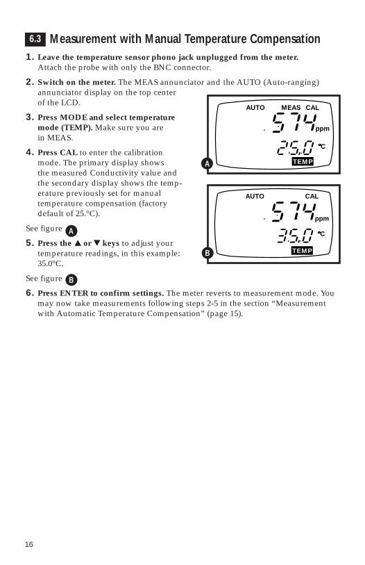
Measurement with Manual Temperature Compensation1. Leave the temperature sensor phono jack unplugged from the meter.
Attach the probe with only the BNC connector.
2. Switch on the meter. The MEAS annunciator and the AUTO (Auto-ranging)annunciator display on the top center of the LCD.
3. Press MODE and select temperature mode (TEMP). Make sure you are in MEAS.
4. Press CAL to enter the calibration mode. The primary display shows the measured Conductivity value and the secondary display shows the temp-erature previously set for manual temperature compensation (factory default of 25.°C).
See figure
5. Press the ▲ or ▼ keys to adjust your temperature readings, in this example:35.0°C.
See figure
6. Press ENTER to confirm settings. The meter reverts to measurement mode. Youmay now take measurements following steps 2-5 in the section “Measurementwith Automatic Temperature Compensation” (page 15).
A
B
TEMP
C
AUTO CAL
ppm
B
C
AUTO MEAS
TEMP
CAL
ppm
A
6.3
17
7. HOLD function
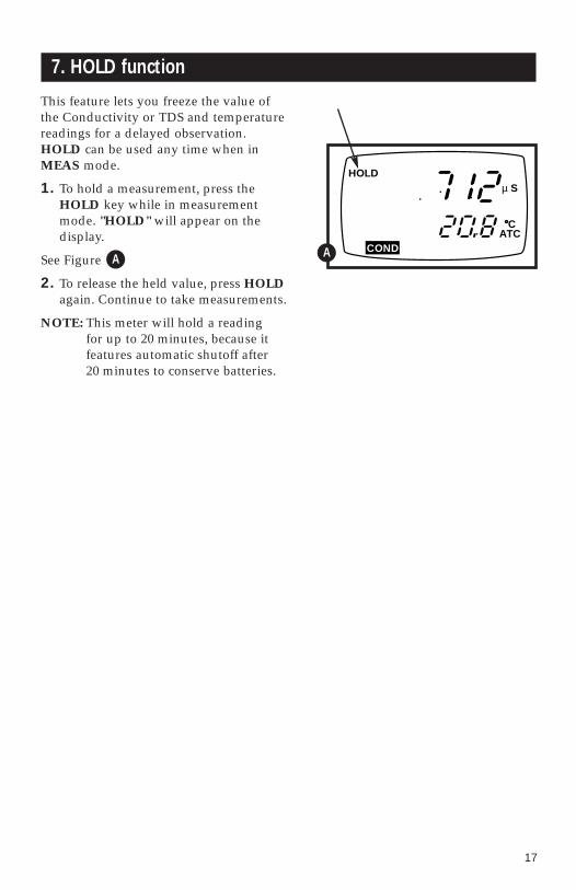
This feature lets you freeze the value of the Conductivity or TDS and temperature readings for a delayed observation. HOLD can be used any time when inMEAS mode.
1. To hold a measurement, press theHOLD key while in measurementmode. "HOLD" will appear on the display.
See Figure
2. To release the held value, press HOLDagain. Continue to take measurements.
NOTE: This meter will hold a reading for up to 20 minutes, because it features automatic shutoff after 20 minutes to conserve batteries.
CATC
µ SHOLD
CONDAA
18
8. Probe Care and Maintenance
Keep the conductivity probe clean. Rinse the probe twice, and gently swirl it whileyou take readings. For best accuracy, soak a dry probe for at least 5 to 10 minutes orlonger before calibration or taking readings. Wash the probe with deionized or tapwater before storing it. Never scratch the stainless steel portions with a hard sub-stance. Do not strike the probe against any hard surface.
Do not make continuous contact with your solutions. Readings rise over a continu-ous period of time if you soak your probe.
Do not immerse the probe in oily solutions. Clean the electrode thoroughly byimmersing it in an agitated mild detergent bath. Wipe the probe with a soft tissuepaper. Wash thoroughly in tap water and then in deionized water. Recalibrate themeter after cleaning the probe.

19
9. Probe Replacement
Your meter and probe have been factory calibrated to each other for maximum accuracy. If you notice a reduction in accuracy after replacing your probe, perform a zero calibration and two-point temperature calibration.
Zero calibrationNOTE: the probe must be dry and in air for zero adjustment.
1. Connect the BNC and phone jacks of the probe to the conductivity meter.
2. Turn the meter off.
3. Press CAL/MEAS and then press ON/OFF, while still holding downCAL/MEAS. Release ON/OFF before releasing CAL/MEAS.
4. Press ENTER three times, and then press CAL/MEAS one time. The LCD shows r1.0 on the secondary display and 0.00 µS on the primary display. The r1.0 indicatesthat you are in the first, or lowest range.
See figure
5. Press ENTER to calibrate the range or CAL/MEAS to skip calibration of the range.
6. At each of the measurement ranges, press ENTER if zero adjustment is required. Once ENTER is pressed, a value displays on the LCD. Wait until the value is low and as stable as it can be before pressing ENTER again. This step adjusts zero for the selected range.
See figure
7. Repeat step 6 for the other ranges if necessary. If you do not want to repeat this step, press CAL/MEAS to skip to the next range.
COND
CAL
B
µ S
CAL
CONDAA
B
9.1
20
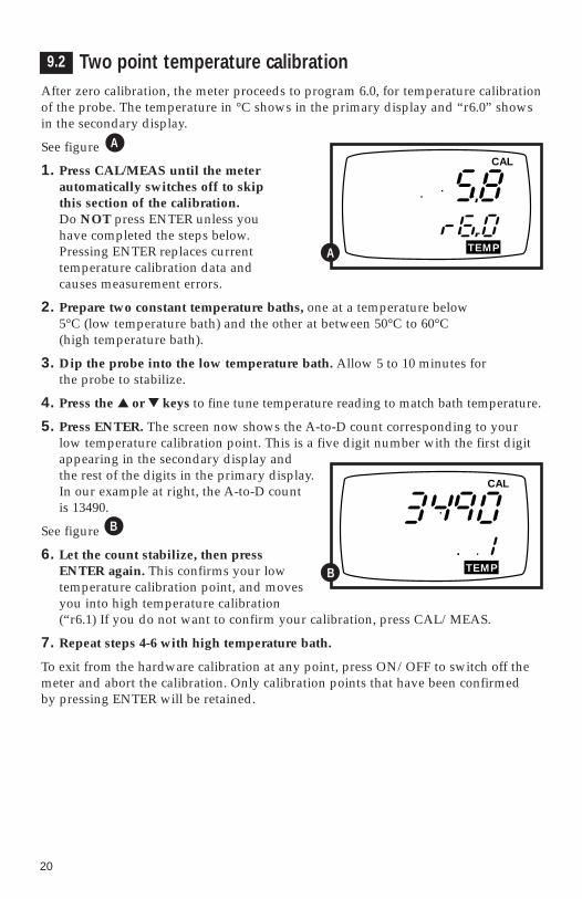
Two point temperature calibrationAfter zero calibration, the meter proceeds to program 6.0, for temperature calibrationof the probe. The temperature in °C shows in the primary display and “r6.0” showsin the secondary display.
See figure
1. Press CAL/MEAS until the meter automatically switches off to skip this section of the calibration. Do NOT press ENTER unless you have completed the steps below. Pressing ENTER replaces current temperature calibration data and causes measurement errors.
2. Prepare two constant temperature baths, one at a temperature below 5°C (low temperature bath) and the other at between 50°C to 60°C (high temperature bath).
3. Dip the probe into the low temperature bath. Allow 5 to 10 minutes for the probe to stabilize.
4. Press the ▲ or ▼ keys to fine tune temperature reading to match bath temperature.
5. Press ENTER. The screen now shows the A-to-D count corresponding to yourlow temperature calibration point. This is a five digit number with the first digitappearing in the secondary display and the rest of the digits in the primary display.In our example at right, the A-to-D count is 13490.
See figure
6. Let the count stabilize, then press ENTER again. This confirms your low temperature calibration point, and movesyou into high temperature calibration (“r6.1) If you do not want to confirm your calibration, press CAL/MEAS.
7. Repeat steps 4-6 with high temperature bath.
To exit from the hardware calibration at any point, press ON/OFF to switch off themeter and abort the calibration. Only calibration points that have been confirmed by pressing ENTER will be retained.
CAL
TEMPA
TEMP
CAL
B
A
B
9.2
21
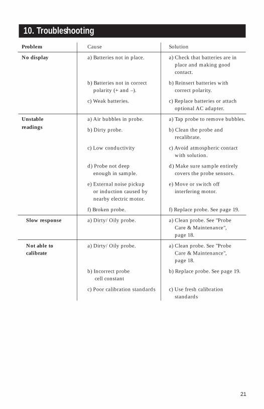
10. Troubleshooting
Problem Cause Solution
No display a) Batteries not in place. a) Check that batteries are inplace and making good contact.
b) Batteries not in correct b) Reinsert batteries withpolarity (+ and –). correct polarity.
c) Weak batteries. c) Replace batteries or attach optional AC adapter.
Unstable a) Air bubbles in probe. a) Tap probe to remove bubbles.readings b) Dirty probe. b) Clean the probe and
recalibrate.
c) Low conductivity c) Avoid atmospheric contactwith solution.
d) Probe not deep d) Make sure sample entirelyenough in sample. covers the probe sensors.
e) External noise pickup e) Move or switch offor induction caused by interfering motor.nearby electric motor.
f) Broken probe. f) Replace probe. See page 19.
Slow response a) Dirty/Oily probe. a) Clean probe. See "Probe Care & Maintenance", page 18.
Not able to a) Dirty/Oily probe. a) Clean probe. See "Probe calibrate Care & Maintenance",
page 18.
b) Incorrect probe b) Replace probe. See page 19.cell constant
c) Poor calibration standards c) Use fresh calibration standards
22
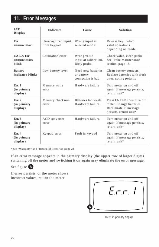
11. Error Messages
LCD Indicates Cause SolutionDisplay
Err Unrecognized input Wrong input in Release key. Select annunciator from keypad selected mode. valid operations
depending on mode.
CAL & Err Calibration error Wrong value Check value, clean probeannunciators input at calibration. See Probe Maintenanceblink Dirty probe. section, page 18.
Battery Low battery level Need new batteries Clean battery contacts.indicator blinks or battery Replace batteries with fresh
connection is bad ones, noting polarity
Err. 1 Memory write Hardware failure Turn meter on and off(in primary error again. If message persists, display) return unit*
Err. 2 Memory checksum Batteries too weak. Press ENTER, then turn off(in primary error Hardware failure. meter. Change batteries.display) Recalibrate. If message
persists, return unit*
Err. 3 ACD converter Hardware failure. Turn meter on and off(in primary error again. If message persists, display) return unit*
Err. 4 Keypad error Fault in keypad Turn meter on and off(in primary again. If message persists, display) return unit*
* See "Warranty" and "Return of Items" on page 28
If an error message appears in the primary display (the upper row of larger digits), switching off the meter and switching it on again may eliminate the error message.
See figure
If error persists, or the meter shows incorrect values, return the meter.
ERR 1 in primary display
A
A

23
12. Specifications
Mode Conductivity TDS Temperature
0.00 to 19.99 µS 0.00 to 9.99 ppm 0 to 80°C
Range 0.0 to 199.9 µS 10.0 to 99.9 ppm (epoxy body probe)0 to 1999 µS 100 to 999 ppm 0 to 100°C
0.00 to 19.99 mS 1.00 to 9.99 ppm (glass body probe)
0.01 µS 0.01 ppm
Resolution 0.1 µS 0.1 ppm 0.1 °C1 µS 1 ppm
0.01 mS 0.01 ppt
Accuracy: ±1% F.S.
Cell constant: 1
Temperature compensation: automatic (ATC) or manual
Reference temperature: factory set at 25°C.
Temperature coefficient: factory set at 2% per °C.
Operating temperature: 0 to 50°C
Power: four 1.5 V AAA batteries (included), approx. 60 hours or AC adapter (optional; order separately on page 24)
Dimensions: Meter: 7.5"L x 3.5"W x 1.75"H (19.1 cm x 8.9 cm x 4.5 cm)
Boxed: 9.2"L x 8.5"W x 2.75"H(23.3 cm x 21.6 cm x 7 cm)
Shipping weight: Meter: 1 lb (0.5 kg)Probe: 0.35 lb (0.2 kg)Complete: 2 lbs (0.9 kg)

24
13. Accessories
Replacement probes and accessories
WD-35607-02 Replacement probe for CON 10
WD-35615-07 AC adapter, 9 VDC to 110 VAC.
WD-35615-08 AC adapter, 9 VDC to 220 VAC.
WD-35615-06 Replacement probe holder.
WD-35615-75 Belt loop portable meter carrying case. Soft case with clear plasticfront panel protects your meter while allowing you to take measurements. Topand side openings let probe and probe connections remain accessible.
OAKTON calibration solutions (in pint bottles)
Conductivity solutions have ±1% accuracy at 25°C
WD-00653-23 Conductivity standard solution 23 µS
WD-00653-16 Conductivity standard solution 84 µS
WD-00653-47 Conductivity standard solution 447 µS
WD-00653-18 Conductivity standard solution 1413 µS
WD-00653-15 Conductivity standard solution 1500 µS
WD-00653-27 Conductivity standard solution 2070 µS
WD-00653-20 Conductivity standard solution 2764 µS
WD-00653-89 Conductivity standard solution 8974 µS
WD-00606-10 Conductivity standard solution 12,880 µS
WD-00653-50 Conductivity standard solution 15,000 µS
WD-00653-32 Conductivity standard solution 80 mS
OAKTON “Singles” calibration solutions
OAKTON “Singles” are convenient go-anywhere solution pouches filled with fresh,premixed calibration standard solutions. ±1% accuracy at 25°C.
WD-35653-10 “Singles” Conductivity standard solution pouches 447 µS
WD-35653-11 “Singles” Conductivity standard solution pouches 1413 µS
WD-35653-12 “Singles” Conductivity standard solution pouches 2764 µS
WD-35653-13 “Singles” Conductivity standard solution pouches 15,000 µS
WD-35653-00 “Singles” solution pouches, rinse water
To order OAKTON accessories, contact your OAKTON distributor.
25
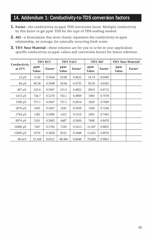
14. Addendum 1: Conductivity-to-TDS conversion factors
1. Factor—the conductivity-to-ppm TDS conversion factor. Multiply conductivity by this factor to get ppm TDS for the type of TDS reading needed.
2. 442—a formulation that most closely represents the conductivity-to-ppm relationship, on average, for naturally occurring fresh water.
3. TDS Your Material—these columns are for you to write in your application-specific conductivity-to-ppm values and conversion factors for future reference.
ConductivityTDS KCl TDS NaCl TDS 4422 TDS Your Material3
at 25°Cppm
Factor1 ppm Factor1 ppm
Factor1 ppmFactor1
Value Value Value Value
23 µS 11.60 0.5044 10.69 0.4652 14.74 0.6409
84 µS 40.38 0.5048 38.04 0.4755 50.50 0.6563
447 µS 225.6 0.5047 215.5 0.4822 300.0 0.6712
1413 µS 744.7 0.5270 702.1 0.4969 1000 0.7078
1500 µS 757.1 0.5047 737.1 0.4914 1050 0.7000
2070 µS 1045 0.5047 1041 0.5030 1500 0.7246
2764 µS 1382 0.5000 1415 0.5119 2063 0.7463
8974 µS 5101 0.5685 4487 0.5000 7608 0.8478
12880 µS 7447 0.5782 7230 0.5613 11,367 0.8825
15000 µS 8759 0.5839 8532 0.5688 13,455 0.8970
80 mS 52,168 0.6521 48,384 0.6048 79,688 0.9961

26
15. Addendum 2: Calculating TDS conversion factors
The meter can be calibrated using TDS calibration standard solutions. The calibration standard only needs to give the TDS value at a standard temperaturesuch as 25°C. To determine the Conductivity-to-TDS conversion factor use the following formula:
Factor = Actual TDS ÷ Actual Conductivity @ 25°C
Definitions:
Actual TDS: Value from the solution bottle label or as a standard you make usinghigh purity water and precisely weighed salts.
Actual Conductivity: Value measured using a properly calibrationConductivity/TDS/Temperature meter.
Both the actual TDS and the actual conductivity values must be in the same magni-tude of units. For example, if the TDS value in is ppm, the conductivity value mustbe in µS; if the TDS value is in ppt, the conductivity value must be in mS.
Check this number by multiplying the conductivity reading by the factor in theabove formula and the result is the TDS in ppm.

27
NOTES:
701-21
16. Warranty
OAKTON warrants this meter to be free from significant deviations in material and workmanship for a period of one year from date of purchase. OAKTONwarrants this probe to be free from significant deviations in material and workmanship for a period of six months from date of purchase. If repair or adjustment is necessary and has not been the result of abuse or misuse within the warrantied time period, please return—freight prepaid—and correction will be made without charge. OAKTON alone will determine if the product problem is due to deviations or customer misuse.
Out-of-warranty products will be repaired on a charge basis.
17. Return of items
Authorization must be obtained from our Customer Service Department beforereturning items for any reason. When applying for authorization, please includedata regarding the reason the items are to be returned. For your protection, itemsmust be carefully packed to prevent damage in shipment and insured against possi-ble damage or loss. We will not be responsible for damage resulting from careless orinsufficient packing. A restocking charge will be made on all unauthorized returns.
NOTE: We reserve the right to make improvements in design, construction, andappearance of products without notice.