Embed Size (px)
Citation preview

INTERNATIONAL FIRE CODE
CHAPTER 31 (2012)NYS FIRE CODE CHAPTER 24
TEMPORARY MEMBRANESTRUCTURES
PRESENTED BY INDUSTRIAL FABRICS ASSOCIATION INTERNATIONAL – TENT RENTAL DIVISION (IFAI-TRD)
NYDOS COURSE #49-6490
IFAI-TRDInformation contained herein is based upon the staking study conducted by Industrial Fabrics Association International – Tent Rental Division (IFAI-TRD). Although based on their study this presentation is not complete. To purchase the complete study you need not become a member IFAI-TRD, however if you do join you will get a copy. To purchase a copy contact IFAI-TRD at:
Jane MonteiTent Rental Division of IFAI1801 County Road BW., Roseville, MN 55113 USATelephone: 800-225-4324Fax: 651-631-9334E-mail: [email protected]
All information remains the property of IFAI-TRD. Its use remains at the sole responsibility of the user. The Presenters and IFAI make to warranties or claims as to usability and therefore no liability in its use. 2
The Presenter
Tom Markel – Owner of Bravo Events Expos Display in Buffalo, NY.
His company has installing tents for over 15 years. He is a member of IFAI-TRD and been participating on the “code committee” for over 11 years with direct involvement in the recent “ballast” study conducted by IFAI-TRD and is an instructor for the IFAI-TRD tent installer program. He is also the IFAI-TRD representative to the ICC.
Tom is also a member of the ICC, NFPA, American Rental Assoc’ (ARA) and Mid Atlantic Tent Renters Assoc’ (MATRA), and is a instructor at the Pennsylvania Amusement Ride Safety Seminar. He gives numerous seminars to the special event industry on life safety, proper electrical installation, emergency preparedness, site review and layout are among the topics he speaks on.
Chapter Contents
1. Types & Terminology of tents as the industry defines them.
2. Proper anchoring and ballasting of tents.
3. Field Inspection of installations, checking for proper assembly.
4. Code requirements from IBC, IFC, NFPA & NEC.
5. Weather related issues for tents.
CHAPTER 1
TENT TYPE & TERMINOLOGY
SCOPE
To familiarize AHJ/CEO with common types of tents, items required for proper installation and terminology use by the industry.
Chapter 1 – Tents & Terminology
For common temporary membrane structures (will call them tents) fall into three main categories:
•Pole – Where the top is help up by a series of poles inside are around the perimeter of the tent and the tent is held up by tension from the anchorage.
•Frame – Where a metal structure holds the top up and the anchorage keeps the tent in place.
•Clearspan – A heavy duty metal structure that, similar to frame but capable of larger spans.

Pole – where the fabric is held up by a series of poles around the perimeter and internally.
Pole tent come in two style, Wind rated Tension Structures and non-wind rated Party Canopies (Canopy should not be confused with the code definition).
Chapter 1 – Tents & Terminology
Tension Structure Tent
Party Canopy tent
<- Straight lines
Curved lines
Frame – where a framework of pipes and fittings is freestanding and the fabric is applied over or into a framework.
Frame tent also come in two basic types, wind rated and non-rated.
Chapter 1 – Tents & Terminology
RATED FRAME TENT
NON-RATED 2” TUBE
Clearspan –Similar to the frame tent but has a more robust structure, with box beams, requiring more precision in designing and installing.
Chapter 1 – Tents & Terminology
POLE TENTSIntegral to there structure is
the anchoring system without which the pole tent would collapse. The anchoring provides the tension to the fabric which keeps all the poles vertical. Anchoring is normally achieved with ropes tied to stakes or web guys, also known as ratchets, and stakes.
Chapter 1 – Tents & Terminology
Chapter 1 – Tents & Terminology
Side Pole >
Tied Jump Rope>
Web Guy orRatchet Strap >
Wind Rated - PoleTension Structure Tent
Wind Rated - PoleTension Structure Tent
< -- Twin Center Poles -->
or main poles
Pole tent have main pole(s) and side poles. In addition a few have quarter poles as well.
Poles must be mechanically attached to the tent using either jump ropes or other means preventing the pole from separating from the tent.
Tied Jump Rope ->
POLE TENTS
A Tension pole tent requires a large amount of tensioning in order to be properly installed. The tent normally has a wind rating generally 70 mph or more in a Type “C” (IBC) location.These tents have reinforcement to qualify for wind ratings. They require more stakes and tension. You can generally identify them by the curved lines and catenary arches, either internal or external, in order to handle the tension in the structure.
Chapter 1 – Tents & Terminology
Tension Structure Tent
Curved lines
Internal arch
External arch ->

POLE TENTSThe canopy or party canopy is a industry term not to be with the IBC and IFC. This however
doesn’t mean at installer will confuse the code or refer to a very large tent as a canopy based on the industry terminology.
These tents generally haven’t been designed with any wind ratings. They are normally installed with ropes and stakes since the ratchets will create too much tension and could tear the tent apart, therefore the tent will generally present with some slack.
This type of tent doesn’t have curved features or reinforcements. The ridge line between center poles will be very straight.
Chapter 1 – Tents & Terminology
Very little curvature >
< Ridge line between polemostly straight across
40x80 Party Canopy Tent
FRAME TENTS
Frame tents also are found with two main types; rated & unrated. Unlike pole tents however, frame tents are free standing and only require anchoring to prevent lifting and/or blowing away.
1st - Unrated frame tents, like party canopies, have no wind ratings. The framework consist of 2” diameter tube, sometime smaller, also referred to as “California Style”. Wider frame tents like 30-40’ require rafter cables.
Chapter 1 – Tents & Terminology
< Crown Fitting
< 2” Pipe
< Intermediate Hip FittingRafter Cable
v
Either steel or aluminum fittings interconnect the tubes and/or beams with fasteners. These fittings follow conventions; corner, crown, hip etc. Also these tent may require additional bracing at the legs and crowns as required by the manufacturer.
Corner Fitting>^
Intermediate Fitting
FRAME TENTS2nd – Rated frame tents, as the term implies, have some engineering to achieve a
wind rating under the IBC. These frame tents will have a beefed up structure with box beams and/or 2”x4” pipes. They also might have a “keder” track to slide the fabric in. This method of fabric installation was borrowed from the last common type of tent – Clearspan. These frame tents could also have Gable or Hip type ends.
The two main differences between Rated & Unrated frame tent are the strength of the framework and the anchoring requirements, with the rated tents having a specific requirements from the manufacturer.
Chapter 1 – Tents & Terminology
Keder Track 2x4 beam >
2x4 beam> 2x4 leg >
Wind rated frame tent
CLEARSPAN TENTSClearspan tents have a more robust structure than frame tents. Most
common are the flat or “Gable” end to these tents. Unlike pole & frame tents, Clearspan tent are anchored through the base plates holding the rafters or arches in place. They don’t require the out guying and staking like frame tents because of their more robuststructure. They can resist wind pressure through the entire structure.
Chapter 1 – Tents & Terminology
Gable End
Bay>
Bay>
CHAPTER 2HOLDING POWER OF STAKES AND
BALLAST
SCOPE
To review the IFAI-TRD industry study concerning the holding power of stakes and ballast for anchoring of tents. To inform and guide the AHJ/CEO in field inspection of tents for compliance with IFC Chapter 24.
IFC 3103.9 (2012) states the following:“Tents, canopies or membrane structures and their appurtenances shall be adequately roped, braced and anchored to withstand the elements of weather and prevent against collapsing.”
As noted in Chapter 1 of this presentation, the most common method of anchoring is using a stake. IFAI-TRD conducted a study done by the University of Illinois to methodically determine the holding power of stakes. This study indicated some basic tenets that apply to stakes and staking. It also found some of the historical practices to be less effective than many people, including long time tent installers, believed. The baseline reference for the study was a 1” diameter x 36” long smooth stake vertical installed with 2 inches exposed above the ground.
We will review the IFAI-TRD staking study based on what was found to be the most effective and less effective practices.
All stakes will resist being pulled out to some extent and will fail given enough force, the difference is how to get the most bang for the buck.
Chapter 2 – Proper Staking

The items found by the study that maximize and minimize stake holding power were:
• How do you like your stake – Is their any difference between the types of stakes.
• Size matters – The length and diameter effect holding power.• Deep Cover – How far should a stake be driven into the
ground.• The Right Angle – The effect the angle of installation has
on holding power.• All tied up – The placement of the anchor line on the holding
power of stakes.• Location, Location, Location – Where the stake is placed
can increase on decrease a stake’s ability to resist being pulled out.
• What’ya holding – How soil types and conditions effect on holding power.
• Ganging Up – Using multiple stakes, stake bars and/or plates to increase holding power.
Chapter 2 – Proper Staking
• How do you like your stake? The IFAI-TRD study found no difference between rebar (smooth or rough) or smooth tent stakes. The only difference with 1” rebar was they structurally they failed at loads above 1600 lbs., therefore the maximum capacity is limited to 1600 lbs.
• The other factors to be discussed where by far more influential in determining a stakes final holding power.
Chapter 2 – Proper Staking
• Size Matters. The diameter of the stake when driven into the ground compresses the soils around it. The larger the diameter the more compression.
• Deep cover. The longer, and therefore deeper the stake is driven increases the amount of soil (the shaded triangle above) in front of the direction of force.
Chapter 2 – Proper Staking
• The Right angle: when a stake is installed at an angle of greater the 15o
from vertical the soil wedge is reduced. This in turn reduces the holding ability of the stake even when the anchoring line is properly attached at ground level.
• All tied up. When the a stake isn’t installed entirely installed into the ground and the anchoring line is attached well above ground level; the reduced soil wedge and ground acting as a fulcrum further reduces holding power.
Chapter 2 – Proper Staking
• Location, Location, Location: For Pole and frame tents the stake should be located at between 35-40o angle from the tent. A good rule of thumb for an installer is the stake should be located no closer than one foot (1ft) less than the height of the side of the tent and no greater than the height of the side. Example: for an 8’ side height the minimum would be 7’; for a 7’ side height the minimum is 6’. Extending the stake location further from the tent increases the play (scope) in a line causing slack which will increase loss of tension and decrases down pressure on the side which, for a pole tent could cause the side pole to kick out especially when the tent is installed with sides or a frame to lift.
Chapter 2 – Proper Staking
CORRECT
• What’ya holding: Soil conditions are highly variable. Factors such as soil composition and density, geological and water tables variations and man-made disturbances effect holding power of the soil. Even pavement will vary, fresh and decayed asphalt don’t hold as well as aged, but good condition, asphalt will.
• Soils with less holding ability are: dry sand, gravel, organic and inorganic silt and loam (topsoil, mulch etc.).
• Soils with good or higher abilities are: Stiff clay, soft (moldable) clay, naturally compacted soils and hard pan (soils that don’t soften when wet).
Chapter 2 – Proper Staking

• Ganging Up: Using multiple stake to increase holding power an appropriate strategy. There are a number of different ways to gang stake. A common “old school” way is to place one stake behind the other. However if done incorrectly very little “extra”holding power is accomplished. The distance between the stakes should be about 1/3 the length or 24” for a 40-42” long stake. The primary stake is providing the greater amount of resistance.
• Using mechanical means like bars and plates will also increase holding power, however, just like the old fashion gang staking above”the additional stakes only increase resistance by 60-85% of a single stake.
Chapter 2 – Proper Staking
<- To Wide ->
The IFAI-TRD study found the following for field/soil capacity. The baseline stake was:
• Stake was a 36” x 1”,• Stake side was smooth,• Stake was driven vertically with
only 2” exposed,• The load was fasten at the
surface, load was pulled at a 45o
angle.In order for installers to have a field
reference for soil/pullout capacity the IFAI-TRD study correlated the amount a stake penetrated with the soil’s hold power. A stake is embedded 24” and struck with a 16 lb sledge hammer using a normal swing. The amount of penetration is correlated in the table below.
Chapter 2 – Proper Staking
Pullout
Capacity
in Pounds
Stake
PenetrationSoil
Consistency
2500Less than
0.2”
Hard
(Very Dense)
2003-6”Soft
(Loose)
800.05-1.5”Stiff
(Med-Dense)
100Greater than
6”Very Soft
(Very Loose)
4001.5-3”Medium
16000.2-9.5”Very Stiff
(Dense)
Estimating capacity for installation and conditions other than baseline uses the following formula:
P = Pb x Ce x Cf x Ci x Cl x Cd
P = Pullout Capacity for a single stakePb= Pullout Capacity for the baseline caseCe= Correction Factor for embedment depthCf = Correction Factor for fastening heightCi = Correction Factor for stake inclinationCl = Correction Factor for load angleCd= Correction Factor for stake diameter
Chapter 2 – Proper Staking
P= Pb x Ce x Cf x Ci x Cl x Cd
Use the tables below for the Correction Factors:
Chapter 2 – Proper Staking
Correction Factor for Embedment
Stake
Embedment (in.)
Ce
36 1.00
34 0.92
32 0.84
30 0.76
28 0.69
26 0.61
24 0.54
Correction Factor for
Fastening Height
Fastening
Height (in.) Cf
2 1.00
4 0.98
6 0.96
8 0.94
10 0.92
12 0.9
Correction Factor for
Stake Inclination
Stake
Inclination Ci0-15o 1.00
15-30o 0.77
Correction Factor for
Load Angle
Stake
Inclination Cl45o
(1H:1V)1.00
53o
(2H:3V)0.85
Correction Factor for
Stake Diameter
Stake
Diameter (in.)
Cd
1.000 1.0
1.125 1.1
Baseline Pullout Capacity (lbs)
Soil
TypeStakePenetration Pb
HardLess 0.02”
2500
Very
Stiff
0.2-
0.5”1600
Stiff0.5-1.5”
800
Med1.5-
3”400
Soft 3-6” 200
Very
Soft6”+ 100
The most common soil condition is Medium. Using the baseline for a 1” diameter stake; medium soil type, holding and correction factors for typical stake installation methods; the following can be demonstrated for their holding power.
Chapter 2 – Proper Staking
Stake inches 40 36 30 24
Baseline 920 800 608 432
2/3 Embedment1 561 432 432 112
½ Fastening2 – 2/3 Embedment1 533 415 236 110
Top Fastening3 – 2/3 Embedment1 494 389 224 106
Stake Angle 30o – ½ Fastening2 – 2/3 Embedment1 411 319 182 85
Stake Angle 30o – Top Fastening3 – 2/3 Embedment1 380 299 172 81
53o Angle - Stake Angle 30o – ½ Fastening2 – 2/3 Embedment1 349 271 154 72
53o Angle - Stake Angle 30o – Top Fastening3 – 2/3 Embedment1 323 254 72 69
1Embedment is 2/3 the length of the stake.2Fastening is affixing anchor line half way on the exposed length of the stake.3Top fastening is affixing the anchor line at the top of the exposed length of the stake.
The IFAI-TRD study also covered Gang staking. As stated earlier, Gang staking does increase holding power but doesn’t achieve 100% baseline resistance. The following table and formula were developed by IFAI-TRD to calculate the amount of holding power for gang staking.
Chapter 2 – Proper Staking
Pg = Pb x Ef
Pg – Capacity of the stake group.
Pb – Holding power of the baseline stake.
Ef – Effectiveness coefficient for the group of stakes from the table.
Group Configuration Ef
Double Staking 1.22
Three Stakes installed in a line perpendicular to direction of pull
2.76
Three Stakes installed in a line perpendicular to direction of pull, greater than 15 degree incline1 2.46
Six Stakes installed in a line perpendicular to direction of pull
4.68
Four Stakes installed in two columns & two rows connected with a gang plate
3.48
Six Stakes installed in two columns & three rows connected with a gang plate
4.56
Note: Table assumes Pb is baseline, substitute calculated holding power if baseline is not used.
1Baseline stake was substituted to demonstrate loss of holding power.

The result of gang staking can be seen in the following table:
Chapter 2 – Proper Staking
STAKE 3 STAKES IN A BAR6
STAKESGANG PLATE
LENGTH HOLDING DOUBLE VERTICAL 15> DEG IN BAR 4 STAKES 6 STAKES
COEFFICIENT > 1.22 2.76 2.46 4.68 3.48 4.56
40 920 1122 2539 2263 4306 3202 4195
36 800 976 2208 1968 3744 2784 3648
30 608 742 1678 1496 2845 2116 2772
24 432 527 1192 1063 2022 1503 1970
Note: Stiff soil holding power assumed. All except 3 stake bar with greater than 15 degree installation use baseline condition.
Keeping in mind that Manufacturer’s instructions for installation trump the following there is some common threads for staking pole and frame tents that can help guide an installer and AHJ to determine if these types of tents have been anchored sufficiently.
For non-rated pole tents 5-10 lbs/ sqft for holding power is required. For rated tents this will increase to 15-20 lbs/ sqft for holding power or higher to achieve certification.
Example and 40x60 pole (2400 sq ft) party canopy tent would require a minimum of12,000 lbs. of holding power. If we used the base line stake; 36” x 1”, at medium soil consistency; the tent would require 15 stakes for installation. If this same tent were a tension structure the calculation would increase to a minimum 36,000 lbs and 45 stakes required. If the length of the stake was 40” x 1”this would reduce the necessary amount of stakes to 13 for non-rated and 39 for a rated tent.
Chapter 2 – Proper Staking
Chapter 2 – Proper Staking Chapter 2 – Proper Staking
Sample Manufacturers staking layout.

Keeping in mind that Manufacturer’s instructions for installation trump the following there is some common threads for staking pole and frame tents that can help guide an installer and AHJ to determine if these types of tents have been anchored sufficiently.
Frame tent follow along the same line as pole tents. Although tension is used for holding the tent up, since the frame does that, they require anchorage to prevent them from lifting, being pushed or torqueing from the wind. For non-rated frame tents, using a minimum of 5-10 lbs is still best. The State of Kentucky has just modified their codes calling for a minimum of 5 lbs/ sqft.
Remember this is using the “maximum” provide by the baseline for the soil conditions. If stakes are not installed for pole and frame tents in the baseline method, more stakes will be required.
Chapter 2 – Proper Staking
38
Chapter 2 – Proper Staking
39
Chapter 2 – Proper Staking
IFAI-TRD commission a study on how to ballast a tent. This study was conducted by Clemson University. The results were far more complex than the staking study and required a “tool” be used to since the “math” is more complex than most installers or AHJ’s would be able to accomplish. The tool is available to members of IFAI-TRD and they are able to print out the result of each calculation. As the AHJ, if a tent is being ballasted, you should require proof of a calculation based on the non-rated 5-10 lbs/ sqft or manufacturer’s certified loads for the tent as entered into the tool.
Chapter 2 – Ballasting
The study revealed an number of general facts about ballasting:
•1 lb or weight never equals 1 lb of ballast.
•The tent type effect how the tent can be ballasted.
•The surface and whether its wet or dry can effect the required ballast.
•The type of ballast, like concrete or a plastic drum effects the ballast’s ability to hold a load.
•The physical profile and placement also are considered when ballasting. Multiple formulas are used to determined which condition is the most severe.
Chapter 2 – Ballasting
The study identified four ballasting methods referred to as configurations.
Chapter 2 – Ballasting
Configuration A is generally used for Clearspan tent where the ballast plate is attached to tent upright. The Fx is the lateral force to be resisted according to the Manufacturer and the Fy is the uplift. The weight, width and location of the center of the ballast is need to calculate part of the formula. The modifier is a rubber or plywood used to increase the surface friction.

Configuration B is similar to A in that a plate is attached to the upright of the tent. B is generally to be used on a frame tent where both Fy & Fx and the “T” tension also needs to be resisted by the ballast. The “T” is the outguy that would normally have to be stake but instead is attached to the ballast. The formulas take into account the ballast sliding on the plate and require more weight.
Chapter 2 – Ballasting
If the ballast is properly tethered to then the formula that predictes sliding is not used, this normally reduces the weight required.
Configuration C places the ballast directly on a surface. Water barrels and concrete blocks are commonly used this way for frame and pole tents. The formulas take into account sliding, lifting and tipping of the ballast.
Chapter 2 – Ballasting
Configuration D would be used on Pole or Frame tents that require a large amount of ballast. The rope or guy would be attached to a plate that the weight would be sitting on top of.
Chapter 2 – Ballasting
INPUT CONFIGURATION
Configuration A B C D
Surface Required Required Required Required
Horizontal – Fx Required Required --- ---
Vertical - Fy Required Required --- ---
Tension - T --- Required Required Required
Modifier Option Option N/A N/A
Ballast Type --- Required Required ---
Ballast Secured --- Option --- ---
Ballast width - w Required Required Required Required
Ballast locate - x Center Guy Guy Center
Ballast height - h --- Required Required ---
Guy height - g --- Required Required Required
Guy Angle Calculated --- Verify Verify Verify
Ballasts
Concrete blocks
Plastic barrel with water
Plastic barrel (blue) with concrete
Plastic barrel (white) with
concrete
Special plastic barrel with water
Steel drum with concrete
Ground Surfaces
Smooth Concrete(Dry & Wet)
Rough Concrete(Dry & Wet)
Asphalt(Dry & Wet)
Gravel(Dry & Wet)
Dirt(Dry & Wet)
Grass(Dry & Wet)
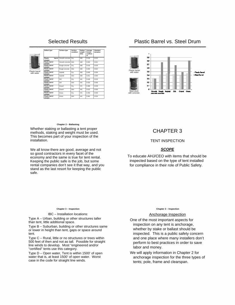
Selected Results
Ballast type Surface type Surface condition
Ballast weight (lbs)
Average friction coefficient
Standard deviation
Plastic barrel w/water
Smooth concrete Dry 460 0.318 0.013
Plastic barrel w/water
Smooth concrete Wet 460 0.263 0.021
Plastic barrel w/water
Rough concrete Dry 460 0.416 0.019
Plastic barrel w/water
Rough concrete Wet 460 0.403 0.022
Plastic barrel w/water
Asphalt Dry 460 0.449 0.004
Plastic barrel w/water
Asphalt Wet 460 0.431 0.003
Plastic barrel w/water
Dirt Dry 441 0.428 0.019
Plastic barrel w/water
Dirt Wet 441 0.420 0.049
Plastic barrel w/water
Gravel Dry 441 0.386 0.028
Plastic barrel w/water
Gravel Wet 441 0.522 0.030
Plastic barrel w/water
Grass Dry 441 0.450 0.030
Plastic barrel w/water
Grass Wet 441 0.462 0.010
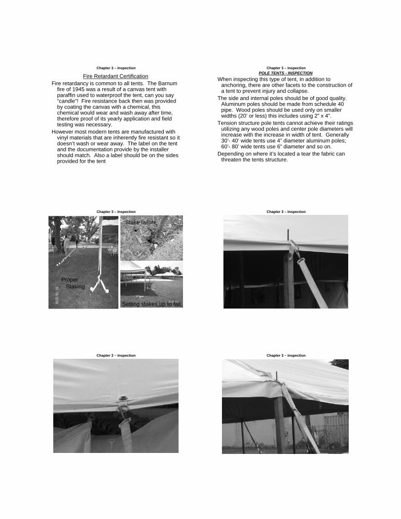
Plastic barrel with water
Plastic Barrel vs. Steel Drum
Plastic barrel with water
Steel drum with concrete
Whether staking or ballasting a tent proper methods, staking and weight must be used. This becomes part of your inspection of the installation.
We all know there are good, average and not so good contractors in every facet of the economy and the same is true for tent rental. Keeping the public safe is the job, but some rental companies don’t see it that way, and you stand as the last resort for keeping the public safe.
Chapter 2 – Ballasting
CHAPTER 3
TENT INSPECTION
SCOPE
To educate AHJ/CEO with items that should be inspected based on the type of tent installed for compliance in their role of Public Safety.
Chapter 3 – Inspection
IBC – Installation locations:Type A – Urban, building or other structures taller than tent, little additional space.Type B – Suburban, building or other structures same or lower in height than tent, gaps or space around tent.Type C – Rural, little or no structures or trees within 500 feet of then and not as tall. Possible for straight line winds to develop. Most “engineered and/or “certified” tents use this category.Type D – Open water, Tent is within 1500’ of open water that is, at least 1500’ of open water. Worst case in the code for straight line winds.
Anchorage Inspection
One of the most important aspects for inspection on any tent is anchorage, whether by stake or ballast should be inspected. This is a public safety concern and one place where many installers don’t perform to best practices in order to save labor and money.
We will apply information in Chapter 2 for anchorage inspection for the three types of tents; pole, frame and clearspan.
Chapter 3 – Inspection
Fire Retardant CertificationFire retardancy is common to all tents. The Barnum
fire of 1945 was a result of a canvas tent with paraffin used to waterproof the tent, can you say “candle”! Fire resistance back then was provided by coating the canvas with a chemical, this chemical would wear and wash away after time, therefore proof of its yearly application and field testing was necessary.
However most modern tents are manufactured with vinyl materials that are inherently fire resistant so it doesn’t wash or wear away. The label on the tent and the documentation provide by the installer should match. Also a label should be on the sides provided for the tent
Chapter 3 – Inspection
POLE TENTS - INSPECTION
When inspecting this type of tent, in addition to anchoring, there are other facets to the construction of a tent to prevent injury and collapse.
The side and internal poles should be of good quality. Aluminum poles should be made from schedule 40 pipe. Wood poles should be used only on smaller widths (20’ or less) this includes using 2” x 4”.
Tension structure pole tents cannot achieve their ratings utilizing any wood poles and center pole diameters will increase with the increase in width of tent. Generally 30’- 40’ wide tents use 4” diameter aluminum poles; 60’- 80’ wide tents use 6” diameter and so on.
Depending on where it’s located a tear the fabric can threaten the tents structure.
Chapter 3 – Inspection
Chapter 3 – Inspection
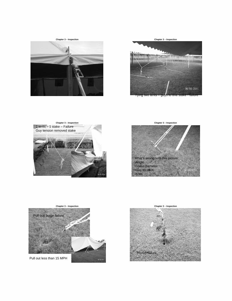
ProperStaking
Stake failure
Setting stakes up to fail
Chapter 3 – Inspection
Chapter 3 – Inspection Chapter 3 – Inspection
Chapter 3 – Inspection Chapter 3 – Inspection
Tying two tents – guys to one stake - failure
Chapter 3 – Inspection
2 tents – 1 stake – FailureGuy tension removed stake
Chapter 3 – Inspection
What’s wrong with this picture:•Angle•Stake diameter•Guy location•Knot
Chapter 3 – Inspection
Pull out less than 15 MPH
Pull out/ bulge failure
Chapter 3 – Inspection
Trench failure

Chapter 3 – Inspection
Low quality guys with only a few 100 lbs.. of capacity make bad guys.Note the stakes.
POLE TENTS - INSPECTIONAnother key requirement for pole tents are “jump ropes”. These rope attach
to the tent fabric near a point adjacent to where the pole is inserted. A properly attached rope keeps the pole from falling out, especially critical for side poles, and keeps the fabric attached to center and, if any, quarter poles should some tension be lost in the pole tent. For these taller poles their should be at least one “hitch” higher up on the pole in addition to being tied off lower down.
One practice that shouldn’t be allowed is looping over the side pole pin. The rope or guy is not attached to the fabric of the tent and if the pole should dislodge the rope or guy will disconnect from the tent.
Lastly inspecting for any of the following:Tears or other signs of weaknesses in the fabric, other than in the valance of the perimeter.Frayed ropes or web (ratchet) straps.Properly tied knots, located near or at ground level. Should not use “dog bones” for anything but a camping tent.
Chapter 3 – Inspection
Chapter 3 – Inspection Chapter 3 – Inspection
Chapter 3 – Inspection
Centerpole jump rope with “hitch”near top of pole.
Inspection item
Chapter 3 – Inspection
Open hooks not a positive attachment.

Chapter 3 – Inspection
Tying toother objects likeTree & fences notallowed
Note: both side poles have fallen out.
Chapter 3 – Inspection
Any tent should be
in reasonable shape or
“good repair”. Special attention should be
paid to where the
tents, especially pole tents, have the
guy attached.
Guy plateNot
attached
Frayedrope
Rain flapTorn – not
critical
Chapter 3 – Inspection Chapter 3 – Inspection
Chapter 3 – Inspection Chapter 3 – Inspection

Chapter 3 – Inspection Chapter 3 – Inspection
FRAME TENTS - INSPECTION
Inspecting a frame tent is different than a pole tent in many ways. Since the structure is free standing a tear in the fabric may only cause a leak but not a public danger from collapse. The real key is to look for proper assembly of the fittings and pipes or beams. Nails, undersize bolts or empty holes without pins or bolts between interlocking pieces can alert a CEO/AHJ to an improper and dangerous assembly.
Chapter 3 – Inspection
FRAME TENTS - INSPECTION
Mix and don’t match. Generally the lower part of a frame tent can be more substantial than the upper part. For example the legs and perimeter pipes are 2”x4” and the upper pipe are 2” could be a proper assembly. But if the upper pipes were 2”x4” and the legs and/or perimeter beams were only 2” then undue stress would be place on these lower structural members, and with the addition of wind and/or precipitation, could become overwhelmed and collapse.
Looking for consistency of parts and connections; a steel pipe for a leg where others are aluminum, some nails or bolts in some fittings when others have pins or clips. The problem for the CEO is that manufacturers used different methods and parts to achieve assembly of their frame.
Chapter 3 – Inspection

Chapter 3 – Inspection
40’ wide Keder track wind rated tent – Eureka TT+
Chapter 3 – Inspection
Chapter 3 – Inspection
Another good one, The leg in not pinned but resting on top of the bolt, therefore its not attached. The pipe on the eave is not a 2” tube but a EMT electrical conduit. It is also not connected to the fitting, stopped by the bolt.
Chapter 3 – Inspection
Chapter 3 – Inspection Chapter 3 – Inspection

Chapter 3 – Inspection
Tent is on water barrels. No pins in legs.
Leg removed per customer request.
Chapter 3 – Inspection
Crown fitting no pins
Chapter 3 – Inspection Chapter 3 – Inspection
No out guy staking
Chapter 3 – Inspection
20 x 20 frame push pole tent. Note the staking.
Chapter 3 – Inspection

Chapter 3 – Inspection
Only 2 stakes instead of 4 – tent can flip
Chapter 3 – Inspection
Besides the fire extinguisher, this type of tent and fitting has push
button. This type will never have a high wind rating.
Chapter 3 – Inspection Chapter 3 – Inspection
Note the water level
Chapter 3 – Inspection
How many things can you find wrong here
CLEARSPAN TENTS - INSPECTION
Clearspan or structure tents are engineered to be wind rated. If staked through the base plate it is the opposite side that resists wind uplift and pressure. If ballasted it’s the windward side.
Like frame tent they need to be bolted properly. Unlike frame tents they don’t rely on out-guying for structural stability.
This type of tent can be multi story. It can also be assembled or anchored wrong.
Chapter 3 - Inspection Chapter 3 – Inspection
Clearspan in Centennial Park - Atlanta, GA
Chapter 3 – Inspection
Clearspan drawingsNote: holes for staking
in the base plates. Cross bracing of the
bay. Clearspan’sshould have every 3
bay braced, minimum of 2 bays per tent.
Chapter 3 – Inspection
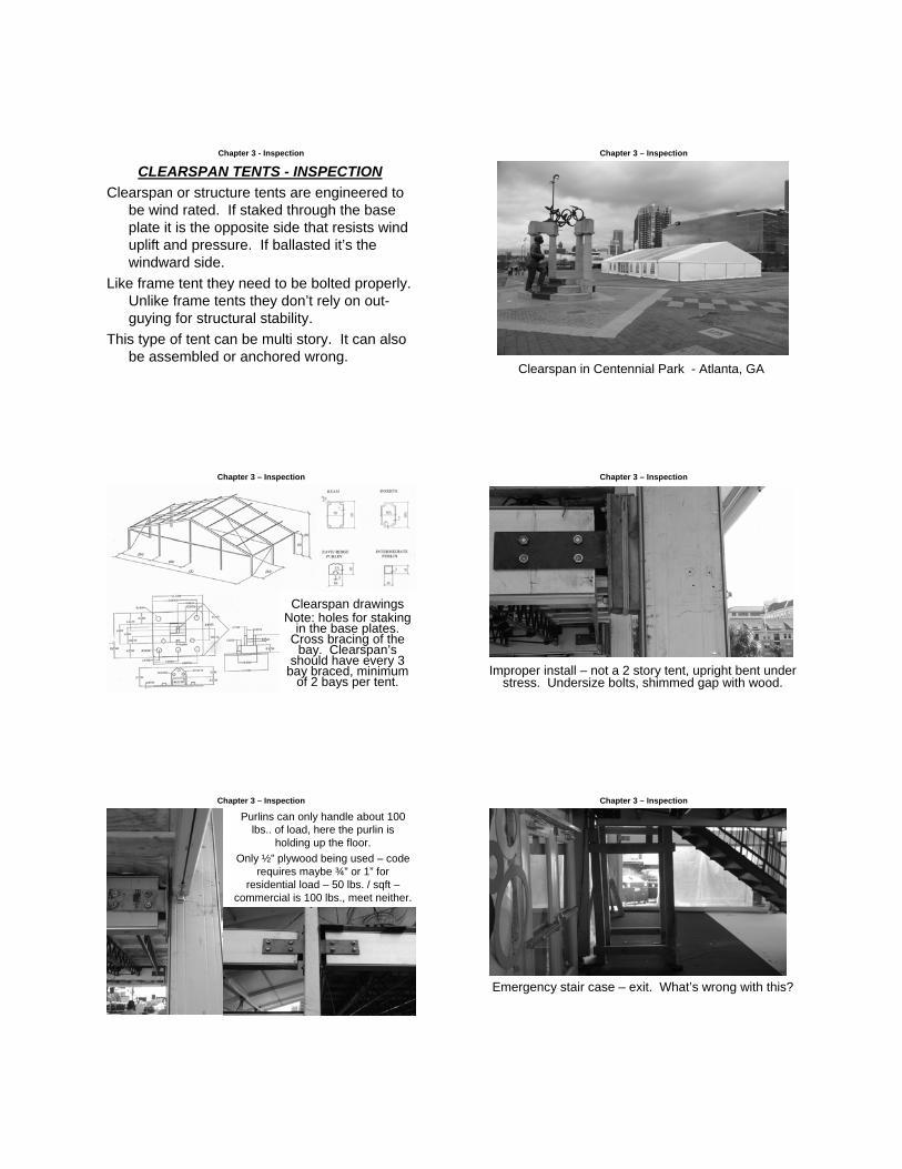
Improper install – not a 2 story tent, upright bent under stress. Undersize bolts, shimmed gap with wood.
Chapter 3 – Inspection
Purlins can only handle about 100 lbs.. of load, here the purlin is
holding up the floor.
Only ½” plywood being used – code requires maybe ¾” or 1” for
residential load – 50 lbs. / sqft –commercial is 100 lbs., meet neither.
Chapter 3 – Inspection
Emergency stair case – exit. What’s wrong with this?

Chapter 3 – Inspection
Proper anchoring of clearspans in necessary like any tent. When staked, the clearspan will resist, unlike a frame tent, on the leeward side by transferring the load through the framework.
However, when you ballast a clearspan, it’s the windward side that resists the wind loads. Plates are normally attached to the base plate or integrated into a ballast plate as covered in Chapter 2. The manufacturer will specify the amount of ballast required to prevent lift and horizontal movement. Using the IFAI-TRD ballast study the installer can calculate the amount of weight need, however under ballasted and improper techniques can cause a engineered/ certified clearspan to fail.
Chapter 3 – Inspection
The tensioner is not a proper connection point for clearspan, the 3,200 lbs. block is not enough to ballast this tent. This company lost this very same
tent in a 45 mph wind.
Chapter 3 – Inspection
Even smaller blocks (1200-1600) used
where 3,000 lbs.
is not enough. This tent
nearly suffer the same fate when the
wind got to 45 mph.
Note: This location would be considered a Type A or B.
CHAPTER 4CODE REQUIREMENTS
SCOPETo review requirements of Chapter 24 for Temporary & Permanent Tents, Canopies
& Membrane Structures.
Since the Hartford Connecticut Barnum and Bailey Brothers tent fire (July 6, 1944) a major focus has been fire protection of tents. It is not the only focus, however, the constructions methods, limiting use and occupancy have also been included in code requirements. An AHJ/CEO today solely focusing on fire retardant materials fails to accomplish their job in securing public safety. Although fire is a hazard, it is not the sole threat to the public.
This presentation will cover only tents and not Air Supported structures that are pressurized for the purpose of supporting the membrane covering.
We will review some of the critical code requirements for tents,which will include fire retardant materials, but also requirements on construction, location of services, occupancy and so on. Some of these requirements need to be met in the pre-permit and permit process then carried through to the actual installation.
However, whether there is a permit required or not, code must befollowed. The question is, do you only stop at a stop sign or light if the cop is there to give you a ticket?
Chapter 4 – Code RequirementsFor the purpose of this presentation code requirements for tents, not air support structures
will be reviewed. Code sections will be paraphrased (….) eliminating references such as tents, canopies and membrane structures for brevity.
Chapter 4 – Code Requirements
CODE SECTION COMMENTARY
107 IBC - Administration
107.1 IBC – Permits authorized with 180 day time limit unless extension approved by AHJ.
107.2 IBC – Requires conformance to requirements of Structural Strength, Fire Safety, Egress and ADA.
107.3 IBC – Temporary Power must conform to Electrical Code (NEC).
Authorizes permits for temporary structures and then defines temporary as 180 or less. An applicant must specify a time period not to exceed 180 days. This section doesn’t regulate temporary structures which is the scope of Section 3103.
Call for conformance to other IBC sections and other codes like IFC, and therefore NFPA and the NEC.
3103 IBC – Temporary Structures
3103.1 IBC – Restates the 180 day limit and requires compliance with the IFC
3103.2 IBC – Construction Documents require to include site plan with location of tent(s), egresses delineated and occupant load(s).
Most other requirement of 3103 are further outlined in the IFC.
Construction documents as defined in IBC Chapter 2 include written, graphic, pictorial documents. Also pertinent information on location, seating capacity, construction and all mechanical and electrical equipment.
This should be part of the permit process. Drawings need to ensure proper spacing for items from the tent as required by the IFC.

Chapter 4 – Code RequirementsCODE SECTION COMMENTARY
3102 IBC
Requires membrane materials to be either noncombustible or fire resistant. These materials must comply with either Section 703.4 of the IBC covering noncombustible.
These materials must comply with either Section 703.4 of the IBC for noncombustible or NFPA 701 for fire resistant materials.
Chapter 24 – IFC (2009)
Tents, Canopies and other Membrane Structures
IFC section that includes tents but also Air Supported (Dome) structures. Chapter 24 cover both temporary and permanent structures.
2402.1 IFC – Definitions
Canopy – A structure, enclosure or shelter constructed of fabric or pliable materials supported by any manner, except by air, or the contents it protects, and is open without sidewalls or drops on 50% or more of the perimeter.
This code definition should not be confused with the “party canopy” as understood in the tent industry. A party canopy could fall under this definition if 75% of the perimeter is without sidewalls or drops since the IFC definition includes free standing structure and architectural projections from an building to provide overhead weather protection, a means of identity or decoration. See IFC figure 2402.1(3).
Chapter 4 – Code RequirementsCODE SECTION COMMENTARY
2402.1 IFC – Definitions
Tent – A structure, enclosure or shelter constructed of fabric or pliable materials supported by any manner except air or the contents that it protects.
A tent is a free standing structure, either temporary or permanent. See IFC Figure 2402.1(4).
2403.2 IFC – Approval required. …. structures having an area in excess of 400 sq ft and canopies in excess of 700 sq ft shall not be erected, operated or maintained for any purpose without first obtaining a permit and approval from the fire code official.
Exceptions:
1. Recreational camping tents
2. Fabric canopies open on all sides which comply with the following:
2.1 Individual canopies having a maximum size if 700 sq ft.
2.2 Aggregate area of multiple canopies placed side by side without a fire break clearance of 12’, not exceeding 700 sq ft
2.3 A minimum clearance of 12’ to all structures and other tents.
This section sets the minimum size of a structure that requires approval.
Exception 1 covers tents normally used by families or small groups for short periods under varying condition that are difficult or impossible to police.
For Exception 2 all items must be met (2.1-2.3) to qualify.
Chapter 4 – Code RequirementsCODE SECTION COMMENTARY
2403.3 IFC – Place of Assembly
…. a place of assembly shall include a circus, carnival, tent show, theater, skating rink, dance hall or other place of assembly in or under which persons gather for any purpose.
By all means not all inclusive, this section gives examples of places of assembly. Discretion is left the code official as to whether it is a place of assembly. See NFPA Life Safety code for further examples.
2403.4 IFC – Permits shall be required as set forth in Section 105.6 & 105.7
2403.5 IFC – Use Period
… shall be used for a period of not more than 180 days within a 12 month period on a single premise”.
These sections are similar to IBC 107 requiring permits and defining what “temporary” is. The only addition to “temporary” in 2403.5 is the 12 month period at a location.
2403.6 IFC – Construction Documents
A detailed site & floor plan for tents, canopies or membrane structures with an occupant load of 50 or more shall be provided….
….floor plan shall indicate details of the means of egress facilities, seating capacity, arrangement of the seating and location and type of heating and electrical equipment.
This section is more detailed than the IBC 3103.2 with the requirements starting at occupancy loads of 50 people. This places the designer, applicant and inspector on the “same page” helping to reduce conflicts in the field during an inspection.
Chapter 4 – Code RequirementsCODE SECTION COMMENTARY
2403.7 IFC – Inspections
The entire tent….shall be inspected at regular intervals, but not less than two times per permit use period, by the permittee, owner or agent to determine that the installation is maintained in accordance with this chapter.
Exception: Permit use period of less that 30 days.
For tent installation for 30 days or greater and minimum of 2 inspections per 30 day period. The fire inspector or building code official is not require to re-inspect (unless they want to), the permit holder, owner or the tent installer acting as agent is required to carry out inspections for tents installed over 30 days.
2403.7.1 IFC – Inspection Report
When required by the fire code official, an inspection report shall be provided and shall consist of maintenance, anchors and fabric inspections.
Requirement for written documentation of the inspections in not mandatory, therefore the fire code official must inform the permit holder if they require a written report. Although it covers maintenance, anchors and fabric, the report format is left to the permit holder, owner or tent installer as agent.
2403.8.1 IFC – Access
Fire apparatus access roads shall be provided in accordance with Section 503.
This is where pre-planning is necessary. Distances should be measured beyond staking so as not to interfere with access. Also plan on sufficient area for egress in addition to access for First Responders.
Chapter 4 – Code RequirementsCODE SECTION COMMENTARY
2403.8.2 IFC – Location
…. structures shall not be located within 20 ft of lot lines, building, other tens, canopies or membrane structures, parked vehicles or internal combustion engines. For the purpose of determining required distances, support ropes and guy wires shall be considered as part of the …. Structure….
Beside setting the distance between structures and source of combustion this section specifically set the outer limits for measurement at the guys and stakes. This means that if the stake must be located 7’or 8’ from the tent it counted as part of the tent and not the distance from other structures and sources of combustion.
2403.8.2 IFC – Location – Exceptions
1. Separation distance between membrane structures … not used for cooking, is not required when the aggregate floor area does not exceed 15,000 sq ft.
2. … Structures … need not be separated from building when all of the following conditions are met:
2.1 The aggregate floor area of the building & membrane structure …. Shall not exceed the allowable floor area including increases as indicated in the IBC.
The 20’ separation is consistent with conventional structures including those the represent above-average fire hazard. Tents certainly pose that threat because the membrane would be involved the a fire and the guys would recoil possibly pulling portions of the membrane from its original position. The 20’ would reduce the likelihood that burning parts of the membrane would not endanger other structures or access.
Chapter 4 – Code RequirementsCODE SECTION COMMENTARY
2403.8.2 IFC – Location – Exceptions Con’t
2.2 The aggregate floor area of the building and …. structure shall not exceed the allowable floor area including increases as indicated in the IBC.
2.3 Required means of egress provisions are provided for both the building and …. structure, including travel distances.
2.4 Fire apparatus access roads are provided in accordance with Section 503.
In addition to 2.3, if the means of egress must flow between tents a minimum of 10’ or more plus any ropes, guys and stakes would be added to the separation required. As an example two pole tents were next to each other and staked 7’ from the tent perimeter, the space between stakes would be minimum of 10’ for egress and distance between the perimeters of the actual tent would be 24’.
Remember all four conditions (2.1-2.4) must be met for Exception 2
2403.8.3 IFC – Location of tents in excess of 15,000 sq ft.
Membrane structures having an area of 15,000 sq ft or more shall be located not less than 50’ from any other tent or structure as measured from the sidewall of the tent … unless joined together by a corridor.
The larger spacing recognizes the increased hazards for the larger structure.
Exception for structures connected by corridors considers the smaller hazard posed by the covering of the corridor. Corridors shouldn’t contain any combustible materials.
Although specifically for air-supported structures large tents like clearspan also are included.

Chapter 4 – Code RequirementsCODE SECTION COMMENTARY
2403.8.4 IFC – Connecting Corridors
Tents or membrane structures are allowed to be joined together by means of corridors. Exit doors shall be provided at each end of such corridor. On each side of such corridor and approximately opposite each other, there shall be provided opening not less than 12’ wide.
Larger Tents are connected by small tents generally referred to as Marquees. They are mostly framed in nature and therefore have set increments for length. Doors should be installed in the larger structure and not in these Marquee tents unless additional doors are installed to provide egress away from and out of the Marquee from a larger structure while providing entry for emergency response personnel.
Additional Commentary 2403.8.4 – Connecting Corridors
The above section calls for openings not less than 12’ wide. The 12’ distance is not consistence with other requirements for exits under IFC Table 2403.12.2. Further, most Marquee tents that would be use to interconnect larger test are based on either 3 meter or 10’ spacing. 12’ might allow emergency vehicles to pass if not for the top of a Marquee tent with only 7 or 8’ of height preventing passage. The intent is correct if egress from a connecting tent is required but should adhere to IFC Table 2403.12.2 not 12’.
2403.8.5 IFC – Fire Break
An unobstructed fire break passageway or fire road not less than 12’ wide & free from guy ropes or other obstructions shall be maintained on all sides of all tents …. unless otherwise approved by the fire code official.
If tents are grouped together & interconnected then access encircling the tents is critical and needs to be pre-approved by fire code officials.
Chapter 4 – Code RequirementsCODE SECTION COMMENTARY
2403.9 IFC – Anchorage Required
Tents, canopies or membrane structures & their appurtenances shall be adequately roped, braced and anchored to withstand the elements of weather & prevent collapsing. Documentation of structural stability shall be furnished to the fire code official on request.
This section give the AHJ the authority to review & approve plans & installations to ensure the tents have been erected using good engineering practices. Chapter 2 of this presentation covered proper staking methods & practices. Most tents won’t require installation plans, however proper anchoring techniques are rarely included in plans, just number, location & sometimes the size of the stakes to be used.
2403.11 IFC – Seating Arrangements
Seating in tents, canopies or membrane structures shall be in accordance with Chapter 10 (IFC).
IFC Chapter 10 cover general occupancy load requirements & calculations. Careful consideration should be given to exits & aisles since membrane structures are different than buildings as outlined in IFC 2403.12.2.
2403.12 IFC – Means of Egress
Means of egress for temporary tents, canopies & membrane structures shall be in accordance with this section.
Because to the nature of tents it is vital tat the means of egress be properly designed & installed. This section regulates the access to, number, location, markings & illumination for egress in tents.
Chapter 4 – Code RequirementsCODE SECTION COMMENTARY
2403.12.1 – Distribution (Exits)
Exits shall be spaced at approximately equal intervals, & shall be located such that all points are 100 feet or less from an exit.
The requirements for equal distribution & 100 foot travel distances are similar to requirements elsewhere in IFC & NFPA. Following these requirements is critical since the use and occupancy can vary widely. Also the number & size of exits for tent is different than Air inflated & permanent structures as outlined under IFC 2403.12.2 below.
2403.12.2 – Number (Exits)
Tents …. Or usable portions thereof shall have at least one exit & not less that the number of exits required by Table 2403.12.2. The widths of means of egress required by Tables 2403.12.2 shall be divided equally among the separate means of egress. The total width of means of egress in inches shall not be less that the total occupant load served by a means of egress multiplied by 0.2 inches per person.
The Ringling Brothers, Barnum & Bailey circus tent fire in 1944 is certainly the driving force behind this section. 167 died & 487 were injured because they were unable to escape the burning tent.
The formula given in this section allows calculation of total exit requirements for any given number of occupants.
Chapter 4 – Code Requirements
OCCUPANT LOAD MIN. NUMBER OF EXIT
MIN. WIDTH OF EXITS (INCHES)
10 – 199 2 72
200 – 499 3 72
500 – 999 4 96
1000 - 1999 5 120
2000 – 2999 6 120
3000 & OVER 7 120
IFC TABLE 2403.12.2
Because the widths between side poles and/or structural members can vary widely the minimum width make sense. The minimum width for any exit is 36 inches so a combination of openings and/or door might be required to meet the width requirement per exit location.
This table in the IFC also contains requirement for air supported structures which we are not covering in this presentation.
Chapter 4 – Code RequirementsCODE SECTION COMMENTARY
2403.12.3 – Exit opening from tents.
Exit openings from tent shall remain open unless covered by a flame-resistant curtain. The curtain shall comply with the following requirements:
1. Curtains shall be free sliding on a metal support. The support shall be a minimum of 80 inches above the floor level at the exit. The curtains shall be so arranged that, when open, no part of the curtain obstructs the exit.
2. Curtains shall be a color, or colors, that contrasts with the color of the tent.
Allowing openings to be covered with a sliding curtain allows occupant comfort against wind, precipitation, temperature extremes or to maintain HVAC while providing an easily opened alternative to doors.
Although the sections calls for a contrasting color for the curtains, a contrasting band around the exit and/or clear vinyl curtains are also acceptable in coordination with proper “Exit”designations.
2403.12.4 – Doors.
Exit doors shall swing in the direction of exit travel. (Section on air supported structures omitted) Opening force at the door edge shall not exceed 15 pounds.
This is consistent with the IBC requirements for conventional doors even though their might be nuisance opening because of wind pressure.
Chapter 4 – Code RequirementsCODE SECTION COMMENTARY
2403.12.5 Aisle.
The width of aisles without fixed seating shall be in accordance with the following:
1. In areas serving employees only, the minimum aisle width shall be 24 inches but not less than the width required by the number of employees served.
2. In public areas, smooth-surfaced, unobstructed aisles having a minimum width of not less than 44 inches shall be provided from seating areas, & aisles shall be progressively increase in width to provide, at all points, not less than 1 foot of aisle width for each 50 persons served by such aisle at that point.
Areas with employees will vary widely. The AHJ should use Chapter 10 of the IFC & IBC to guide their judgment of these areas.
The second requirement covering public occupancy; aisles sizing is based on total occupancy including employees. The AHJ should also keep in mind the approach to the exits, size & number, when reviewing designs. If the door size is 120 inches (10ft) and that is being spread between multiple doors, aisles might have to widen to accommodate access to any series of openings or doors.
2403.12.5.1 Arrangement & Maintenance.
The arrangement of aisles shall be subject to approval by the fire code official and shall be maintained clear at all times during occupancy.
The fire code official is given continued is hereby given continuing authority to inspect arrangements of tents to verify arrangements have not been changed to unacceptable configuration.

Chapter 4 – Code RequirementsCODE SECTION COMMENTARY
2403.12.6 Exit signs.
Exit shall be clearly marked. Exit signs shall be installed at required exit doorways & where otherwise necessary to indicate clearly the direction of egress when the exit serves an occupant load of 50 or more.
Exit sign requirement for tents is based on occupancy load & not on the absence of or some specific amount of side wall coverage to eliminate this requirement.
2403.12.6.1 Exit sign illumination.
Exit signs shall be of an approved self-luminous type or shall be internally or externally illuminated by fixtures supplied in the following manner:
1. Two separate circuits, one of which shall be separate from all other circuits, for occupant loads of 300 or less; or
2. Two separate sources of power, one of which shall be an approved emergency system, shall be provided when the occupant load exceeds 300. Emergency systems shall be supplied from storage batteries or from the on-site generator set, & shall be installed in accordance with the ICC Electrical Code.
Many different requirements are covered for exit signs in this section.
Additional codes calling for and covering exit and egress lighting are:
IBC Chapter 10 (1011.4), IFC Chapter 10 (1011 & 1030),NEC, NFPA 1, 7 & 101.
UL Standard 924 covers design & performance criteria for exit signs and lighting based one the above codes.
Additional commentary about sign illumination follows.
Chapter 4 – Code Requirements2403.12.6.1 Exit Sign Illumination – Additional
CommentaryThis section covers both self-luminous and powered signs.
All signs must be illuminated for no less than 90 minutes. UL standard 924 – Emergency Lighting, spells out the character powered & self-luminous signs.
Self-luminous signs require a separate light source with 5 ft. candles per sq. ft. directed at the sign. General lighting is not sufficient to produce the 5 foot candles (54 lux) nor will it give a dedicated & directed source for a “glow in the dark” sign when the lights are off. Signs should be third party listed and have instructions to remain lighted with 5 foot candles on the occupied side of the sign.
Chapter 4 – Code Requirements2403.12.6.1 Exit Sign Illumination – Additional Commentary
Many event companies use these sign because they think they are more convenient, yet actual compliance is more complicated.For signs supplied with AC and having battery backup; must use an non-GFCI circuit (both NFPA 101 & NEC), this is an exception to the power supplied in outdoor or wet locations requiring GFCI circuits. Many AC supplied signs are modified to disconnect the battery and “save” the charge. Since it can take 24-36 hours to charge a battery for 90 minutes of use this might be a good practice, however there is no way to tell if the battery has been reconnect without testing the sign. A better modification is to switch both AC & DC circuits at the same time with a double pole- single throw switch (DPST). Test the sign (battery) is always a good practice after installation and before occupancy in a tent.
Chapter 4 – Code RequirementsCODE SECTION COMMENTARY
2403.12.7 Means of egress illumination.
Means of egress shall be illuminated with light having an intensity of not less than 1 foot-candle (11lux) at floor level while the structure is occupied. Fixtures required for means of egress illumination shall be supplied from a separate circuit or source of power.
Battery operated exit signs with lights generally will suffice to meet this requirement. The exit signs require a the same specifications for a dedicated source of energy including: non-GFCI power source. and 90 minute time duration.
2403.12.8 Maintenance of means of egress.
The required width of exits, aisles & passageway shall be maintained at all times to a public way. Guy wires, guy ropes & other support members shall not cross a means of egress at a height of less than 8 ft. The surface of means of egress shall be maintained in an approved manner.
Keeping the means of egress clear applies to all structures. Plan should be carefully reviewed by code officials with attention to appurtenances like guy wires & ropes. Drawings should include these features for review.
2404 1 General Temporary & Permanent tents, canopies & membrane structures.
… both temporary & permanent, shall be in accordance with this sections. Permanent tents ….shall. Also comply with the IBC.
The intent of this section is to cover both temporary and permanent tents regardless of the length of use ; that is should be soundly designed so as not to present a hazard to personnel or the
bli d i th ti it i l
Chapter 4 – Code RequirementsCODE SECTION COMMENTARY
2404.2 Flame-resistant treatment
Before a permit is granted, the owner or agent shall file with the fire code official a certificate executed by an approved testing laboratory, certifying that the tent…and their appurtenances, sidewalls, drops & tarpaulins, floor coverings, bunting… shall be composed of flame-resistant material or…treated with flame retardant in an approved manner in accordance with NFPA 701, & that such flame resistance is effective for the period specified by the permit.
Most modern vinyl tents are inherently fire resistant under NFPA 701. Old canvas tents required treatment & re-treatment of fire retardant and therefore third party certification, a hold over from the Barnum Circus fire. The manufacturer of the tent specifies the fire retardancyof the fabric & identifies the manufacturer of the fabric in their certificate & label. See 2404.3-4
This section is consistent with IBC sections 802, 805 &3102.
2404.3 Label
Membrane structures….shall have a permanently affixed label bearing identification of the size & fabric or material type.
This label gives the fire code official important information about the fabric, the design size of the structure & the manufacturer. This label does not identify the installer. Currently there is no standardization as to the format, size or presentation of information.
Chapter 4 – Code RequirementsCODE SECTION COMMENTARY
2404.4 Certification
An affidavit or affirmation shall be submitted to the fire code official and a copy retained on the premises on which the tent…structure is located. The affidavit shall attest ot the following information relative to the flame resistance of the fabric:
1. Names & address of the owners of the tent….structure.
2. Date the fabric was last treated with flame-resistant solution.
3. Trade name or kind of chemical used in treatment.
4. Name of person or firm treating the material.
5. Name of the testing agency & tent standard by which the fabric was tested.
Again most of this was developed after the Barnum circus fire when tent were constructed of natural fabric. Fire retardant material was only accomplished through the use of chemical treatment which had to be reapplied at intervals to maintain its fire-retarding properties.
Most tents are now manufactured using some form of vinyl that meet NFPA 701 large scale standards. Documentation is provided by the tent manufacturer in the label affixed to the tent and certification documentation provided at sale from the manufacturer.

Chapter 4 – Code RequirementsCODE SECTION COMMENTARY
2404.5 Combustible materials
Hay, straw, shavings or similar combustible materials shall not be located within ant tent….structure containing an assembly occupancy, except for materials necessary for the daily feeding and care of animals. Sawdust & shavings utilized for a public performance or exhibit shall not be prohibited provided the sawdust & are kept damp. Combustible materials shall not be permitted under stands or seats at any time. The areas within & adjacent to the tent….structure shall be maintained clear of all combustibles materials or vegetation that could create a fire hazard with 20 feet from the structure. Combustible trash shall be removed at least once a day from the structure during the period the structure is occupied by the public.
The section contains a “laundry list” of unacceptable practices. Readily ignitable materials shouldn’t be used in a tent, including for displays unless they can be made fire-retardant.
Keeping areas under seating free of combustibles removes a significant fire hazard from these areas of high occupant density.
Maintaining a clear 20 ft buffer zone around & outside of the tent removes a potential fuel source from the area & minimizes the possibility of a wind-blown fire causing the structure to ignite. However, not all vegetation is a hazard. Well keep gardens, trees etc will not readily ignite. The fire official should consider this and ask about conditions during he permit process.
Keeping trash cleared both inside & out also removes potential fuel source from the area.
Chapter 4 – Code RequirementsCODE SECTION COMMENTARY
2404.6 Smoking
Smoking shall not be permitted in tents….structures. Approved “No Smoking”signs shall be conspicuously posted in accordance with Section 310.
Because no specification exist for standard signs, each jurisdiction having authority is responsible for establishing its own criteria. To be approved, signs must be large enough to be read from a distance & be worded simply & clearly.
2404.7 Open or exposed flame.
Open flame or other devices emitting flame, fire or heat or any flammable or combustible liquids, gas, charcoal or other cooking device or any other unapproved devices shall not be permitted inside or located within 20 feet of the tent….structures while open to the public unless approved by the fire code official.
The prohibition of open flames & high heat appliances fueled by flammable liquids or combustible gases & solids inside or within 20 ft of a tent removes a potential source of ignition. Small cooking appliances like ones using 8oz butane for a single burner, sternoused to heat water for chaffers or coffee pots or catalytic heaters that are located well away from the wall of the structure are examples of appliances that a code official can allow for use inside a tent.
2404.8 Fireworks
Fireworks shall not be used within 100 ft of tent….structures.
Establishing a 100ft clear zone minimizes the possibility of hot embers time to cool before they could reach the tent membrane.
Chapter 4 – Code RequirementsCODE SECTION COMMENTARY
2404.9 Spot Lighting
Spot or effect lighting shall only be by electricity, and all combustible construction located within 6 ft of such equipment shall be protected with approved noncombustible insulation not less than 9.25 inches thick.
Although incandescent lighting can generate considerable heat, new form of theatrical lighting that are based on LED (light emitting diode) or general lighting using CFL (compact florescent) are considerably cooler& don’t pose the same hazard as incandescent fixtures.
2404.11 Clearance
There shall be a minimum clearance of at least 3 ft between the fabric envelope and all contents located inside the tent….structure.
Intended to give clearance to fire fighters for immobile contents stored in a tent and prevent the stored contents from igniting the membrane, however if proper distances have been maintained between tables & tent sides fire fighters will still have access with movable seating.
2404.12 Portable Fire Extinguishers
Portable fire extinguishers shall be provided as required by Section 906.
Section 906 states that extinguishers are required in Group A occupancies or areas designated by the fire code official. Section 906 also refers to NFPA 10 for guidance on selection & placements of extinguishers. A basic rule of thumb taught to the tent industry is an approved ABC type of every required exit, which generally adheres to Section 906 & NFPA 10 & 101 requirements
Chapter 4 – Code RequirementsCODE SECTION COMMENTARY
2404.14 Occupant Load Factors
The occupant load allowed in an assembly structure, or portion thereof, shall be determined in accordance with Chapter 10.
Whether permanent or temporary, a membrane structure is treated the same way as conventional construction with the additional consideration of the guy rope or anchoring would cause blockage of egress & therefore the code official need to review plans to insure proper egress from a membrane structure.
2404.15 (Also .1) Heating & Cooking Equipment
Heating & cooking equipment shall be accordance with this section.
2404.15.2 Venting
Where vents or flues are used, all portions of the tent….structure shall not be less than 12 inches from the flue or vent.
Because of the nature of a membrane structure, equipment that could provide a source of ignition must be review & regulated. The International Mechanical and Fuel Gas Codes should be followed for installation, venting & use.
The 12 spacing between flues & membrane is intended to prevent possible point of ignition to the membrane.
2404.15.3 Location (Cooking & Heating Equipment.
Cooking & heating equipment shall not be located within 10 ft of exits or combustible materials.
This only represents clearance required from exits & other combustibles, for this type of equipment, and not the required clearances from the membrane structure being heated or one being used as dedicated for cooking.
Chapter 4 – Code RequirementsCODE SECTION COMMENTARY
2404.15.4 Operations
Operations such as warming of foods, cooking demonstrations & similar operations that use solid flammables, butane or similar devices which do not pose an ignition hazard, shall be approved.
Although these operations have authorization the fire code official should make certain they meet the requirements of other subsections within this section.
2404.15.5 Cooking Tents
Tents where cooking is performed shall be separated from other tents….structures by a minimum of 20 ft.
This separation is consistent with 2404.7 covering open or exposed flames and combustible materials.
2404.15.6 Outdoor Cooking
Outdoor cooking that produces sparks or grease-laden vapors shall not be performed within 20 ft from a tent…..structure.
Same need and requirements as 2404.15.5 above.
2404.15.7 Electrical Heating & Cooking Equipment
Electrical cooking & heating equipment shall comply with the ICC Electrical Code.
This section establishes the requirements for this type of equipment and the fire authorities ability to approve to the equipment & installation.
Chapter 4 – Code RequirementsCODE SECTION COMMENTARY
2404.15 LP-gas
The storage, handling & use of LP-gas & LP-gas equipment shall be in accordance with this section.
Because of the nature of membrane structures & possible sources of ignition, this section adds to the general requirements of Chapter 38 for LP-gas regulation.
2404.15.1 General
LP-gas equipment such as tanks, piping, hoses, fittings, valves, tubing & other related components shall be approved & in accordance with Chapter 38 and with the International Fuel Gas Code.
LP-gas installation must meet the minimum standards for conventional installation & inspection requirements.
2404.16.2 Location of Containers
LP-gas containers shall be located outside. Safety release valves shall be pointed away from the tent….structure.
Cylinders greater than 1lb would have to be located outside the tent.
2404.16.2.1 Containers 500 gallon or less
Portable LP-gas containers with a capacity of 500 gallons or less shall have a minimum separation between the container & structure not less than 10 ft.
Consistent with codes covering conventional structures.

Chapter 4 – Code RequirementsCODE SECTION COMMENTARY
2404.16.2.2 Containers more than 500 gal.
Portable LP-gas containers with a capacity of more that 500 gallons (1893 L) shall have a minimum separation between the container & structures not lee than 25 ft.
The separation of 25 ft would also be required from adjacent tents which might require increased spacing between membrane structures to accommodate the clearance. See Section & Table 3804.3 for further information.
2404.16.3 Protection & Security
Portable LP-gas containers, piping, valves & fittings which are located outside & are being used to fuel equipment inside a tent….structure shall be adequately protected to prevent tampering, damage by vehicles or other hazards & shall be located in an approved location. Portable LP-gas containers shall be securely fastened in place to prevent unauthorized movement.
LP-gas containers & equipment must be protected from impacts by vehicles or other objects that could cause damage & leakage. They must also be protected from tampering & vandalism. See IFC Section 3807 for additional guidance on protection & security. Location of container(s) should be included in site drawing for Fire Code official review & approval.
2404.17 Flammable & Combustible Liquids
The storage of flammable & combustible liquids & the use of flammable-liquid-fueled equipment shall be in accordance with this section.
Because of the nature of membrane structures, it is vital that the storage, handling & use of the hazardous materials in or around such structures be carefully regulated using Chapter 34 in general & these additional regulations.
Chapter 4 – Code RequirementsCODE SECTION COMMENTARY
2404.17.1 Use
Flammable-liquid-fueled equipment shall not be used in tents, canopies or membrane structures.
Equipment of any kind that uses a flammable liquid for fuel must not be used inside a tent because of the possibility of fuel leakage & the risk of accumulation of noxious fumes, carbon monoxide & other gases. Fluid leaks could vaporize & reach a flammable concentration. Tents don’t have a consistent ventilation of conventional structures, harmful vapors & fumes are not diluted or dispersed as in conventional structures.
2404.17.2 Flammable & Combustible Liquid Storage.
Flammable & combustible liquids shall be stored outside in an approved manner not less that 50 ft from tents…structures. Storage shall be in accordance with Chapter 34.
The general separation require here is 50 ft for storage containers of combustible liquids. This is consistent with requirements in Table 2206.2.3 for other tanks. More detailed requirements of Chapter 34 depend on whether the liquid is Class I, II or III & the quantity of the liquid being stored. Storage arrangements should be discussed in advance with the Fire Code Official to make certain all parties are in agreement.
2404.17.3 Refueling
Refueling shall be performed in an approved location not less than 20 ft from tents…structures.
This is only a general guideline for refueling station. Fire Code Officials have the authority to approve the selected location. When approving the location Chapter 34 & some sections of 2204-2206 might also apply if vehicles are being refueled.
Chapter 4 – Code RequirementsCODE SECTION COMMENTARY
2404.18 Display of Motor Vehicles
Liquid- & gas-fueled vehicles & equipment used for display within tent….structures shall be in accordance with this section.
The section & following subsections cover the additional requirements for tents when displaying vehicles.
2404.18.1 Batteries
Batteries shall be disconnected in an appropriate manner.
This section is consistent with vehicles display in conventional structures including removing a potential ignition source & possible noxious fumes.
2404.18.2 Fuel Systems
Vehicles or equipment shall not be fueled or defueled within a tent….structure.
All fuelling & defueling must take place outside a tent.
2404.18.2.1 Quantity Limit
Fuel in the fuel tank shall not exceed ¼ of the tank capacity or 5 gallons, whichever is less.
This section is consistent with vehicles display in conventional structures including leak potential & expansion of fuel in tanks causing vapor releases.
2404.18.2.2 Inspection
Fuel systems shall be inspected for leaks.
The inspection requirement is on the party displaying the vehicles or equipment. Inspection should be routine & also gives the Fire Code Official authority to inspect the facility for compliance.
Chapter 4 – Code RequirementsCODE SECTION COMMENTARY
2404.18.2.3 Closure
Fuel tank openings shall be locked & sealed to prevent the escape of vapors.
Locking & sealing fuel tanks prevents tampering & vapors from escaping.
2404.18.3 Location
The location of vehicles or equipment shall not obstruct means of egress.
Consistent with the requirements of Life Safety codes like Chapter 10 or NFPA 101.
2404.18.4 Places of Assembly
When a compressed natural gas (CNG) or liquefied petroleum gas (LP-gas) powered vehicle is parked inside a place of assembly, all of the following conditions shall be met:
1.The quarter-turn shutoff valve or other shutoff valve on the outlet of CNG or LP-gas container shall be closed & the engine shall be operated until it stops. Valves shall remain closed while the vehicle is indoors.
2.The hot lead of the battery shall be disconnected.
The requirements here deal with the specific needs of CNG or LP-gas powered vehicles & are consistent with gas powered vehicles. The same considerations should be give to hydrogen vehicles not specifically cover yet by the code.
The first requirement prevents vapor buildup in confined spaces & the engine compartment . Fuel in a warm engine will “cook off” (vaporize) after the engine is shut down. By choking off the fuel supply before shutting down the engine prevents fuel from remaining in the engine to vaporize latter & become a possible hazard.
Chapter 4 – Code RequirementsCODE SECTION COMMENTARY
2404.18.4 Places of Assembly – Continued
3. Duel-fuel vehicles equipped to operate on gasoline & CNG or LP-gas shall comply with this section & sections 2404.18.1 through 2404.18.5.3 for gasoline-powered vehicles.
The second requirement restates Section 2404.18.1 requirements.
The third requirement covers duel fueled vehicles so that requirements are the same for those powered by gasoline.
Diesel & Hydrogen fueled vehicles should also follow the same procedures even though not specifically mention in this section.
2404.18.5 Competitions & Demonstrations
Liquid- & gas Fueled vehicles & equipment used for competition or demonstrations within a tent….structure shall comply with Section 2404.18.5.1 through 2404.18.5.3
Since a tent could be used for demonstration and/or event this section restates other parts of the codes to insure compliance with use of fueled vehicles within a membrane structure.
2404.18.5.1 Fuel Storage
Fuel for vehicles or equipment shall be stored in approved containers in an approved location outside of the structure in accordance with Section 1404.17.2.
This section requires the site designer, competition manager or other responsible party must have the Fire Code Officials approval for a storage scheme. See Section 3804 & Sections 2203 & 2206 for additional information on LP-gas & CNG.
Chapter 4 – Code RequirementsCODE SECTION COMMENTARY
2404.18.5.2 Fueling
Refueling shall be performed outside of the structure in accordance with Section 2404.17.3
Reference to Section 2404.17.3 requires a 20ft separation between fueling station & tent. See section 3806 for fueling information on LP-gas & 2204,2207 & 2208 for CNG.
2404.19 Separation of Generators
Generators & other internal combustion power sources shall be separated for tents….structures by a minimum of 20ft & shall be isolated form contact with the public by fencing, enclosure or other approved method.
This section is consistent with other separation requirements for equipment driven by combustible fuels.
The isolation from the public is additionally important to prevent contact with hazardous equipment & protect the equipment from vandalism or accidental damage.
2404.20 Standby Personnel
When, in the opinion of the fire code official, it is essential, it is essential for public safety in a tent…structure used as a place of assembly or any other use where people congregate, because of the number of persons, or the nature of the performance, exhibition, display, contest or activity, the owner, agent, lessee shall employ one or more qualified persons, as required &
Having trained and/or qualified personnel or members of the Fire Safety present during large events ensures public safety. The fire code official has the authority to determine when this requirement is necessary. Although a minimum ratio is stated the fire code official can increase that number if they deem it necessary depending upon the crowd size and/or activity taking place.
Con’t

Chapter 4 – Code RequirementsCODE SECTION COMMENTARY
2404.20 Standby Personnel – Con’t
approved, to remain on duty during the times such places are open to the public, or hen such activity is being conducted.
Before each performance or the start of such activity, standby personnel shall keep diligent watch for fires during the time such place is open to the public or such activity is being conducted & take prompt measures for extinguishment of fires that occur & assist in the evacuation of the public form the structure.
There shall be trained crowd managers or crowd manager supervisors at a ratio of one crowd manager/supervisor for every 250 occupants, as approved.
The key is that personnel, other than Fire Safety, must be trained and assist in emergency egress and/or to extinguish fire; and the training procedures should be approved by the fire code official. Trained personnel can be tour guides, service , ushers etc.
Chapter 4 – Code RequirementsCODE SECTION COMMENTARY
2404.21 Vegetation removal
Combustible vegetation shall be removed from the area occupied by a tent….structure, & from areas within 30ft of such structures.
Not all vegetation is readily combustible so preplanning, pre installing site visitation should be conducted to determine if the tent will be located in an area that would contain combustible vegetation. Since weather conditions could change over time, previously acceptable vegetation might with a lack of precipitation; pose a risk at installation. Grasses , gardens might be acceptable but wood chips or hay covering landscaping might pose a risk and would need to be removed.
2404.22 Waste material
The floor surface inside tents….structures & the grounds outside & within a 30ft perimeter shall be kept clear of combustible waste. Such waste shall be stored in approved containers until removed from the premises.
This section extends the removal of trash to an area for 30ft around the outside & the inside of a tent. The increased hazard posed by the membrane structure is recognized in the 30ft perimeter requirement.
CHAPTER 5WEATHER
SCOPETo understand weather considerations and
how they relate to tents.
Wind, precipitation & lightning are the three main weather factors that effect tents.
In reverse order lighting is easy, get out tents are not a good place to be in a lighting storm.
Although you might think that grounding a tent would be a good preventative measure, it’s actually the opposite. Very few tents are hit by lighting, but grounding the metal parts of a tent might increase the chance and direct the strike onto the tent and into occupied area under a tent.
Chapter 5 – Weather
Precipitation is next. Most tents can shed some rainfall, but heavy rainfall, an 1” or more per hour is beyond there ability except for the engineered/ certified tents. Even these will have trouble with excessive rainfall.
Also for pole & frame tents, the soil becoming saturated changes the holding power of the stake as covered in Chapter 2
If you add in hail, the fabric roofs are unlikely to take much and the weight of the hail can exceed the ability of the tent to stay installed like a party canopy or a non-rated frame.
Chapter 5 – Weather
Snow load – Any non-rated tent has a zero snow load capacity. Even a rated pole or frame tents are not required to have a snow load rating for certification. Lastly clearspans have a very low snow load capacity but can be beefed up. Any tent intended to be install during the winter as a place of assembly should be reviewed for snow load if this is a consideration in the Jurisdiction.
Generally a pole tent such not be used in the winter. A good quality frame for up to 20’ widths and ever stronger for 30 & 40’ widths. A snow removal and/or heating program should be in place. Planning should also be in place for evacuation or cancellation in the event of a heavy snowfall.
Chapter 5 – Weather

Now for wind, the single biggest threat to any tent. Although the minimum IBC rating in Chapter 16 for a tent is 70 MPH or 5 min. and 90 MPH for 3 sec., most tent don’t and can’t meet that criteria.
Mother Nature has a way of finding the weakest link and wind is very often the method used. A squall of a short duration or microburst can cause a tent to fail very quickly. This is why proper installation and egress are necessary for setup.
Chapter 5 – Weather
Let’s look a wind ranges and average frequency:0-15 MPH Any time any day
15-25 MPH 7-10 days25-35 MPH 10-25 days35-45 MPH 25-45 days45-60 MPH 45-120 days60-75 MPH 120-365 daysThis doesn’t mean that when you had a 45 MPH
wind you wont have another for 45 days, could have another the very next, these are just averages.
So it really doesn’t matter if the tent is up for a day or 179, eventually you will have one up for a wind event.
Chapter 5 – Weather
Too review, its everyone’s job to work for the safety of the public and employees, however not everyone does this as we’ve seen.
Although we have directly related the presented material to emergency preparedness and event contingency planning it certainly is part of the whole picture. Preventing a tent collapse in minor winds or because of improper assembly and/or installation and being prepared for other, more serious weather events or other incidents is part of the picture.
Conclusion
You as the AHJ are becoming a more important part of all special events. Whether a private party or wedding to a large public events, from a bar in Kansas City to a air show in Huntsville, AL, each with a fatality, the importance of the material presented should help with your obligations to public safety.
Conclusion