Embed Size (px)
Citation preview

i
Numerical modeling of induction assisted subsurface
heating technology
By
Lei Zhang
A Thesis
Submit to the faculty of
WORCESTER POLYTECHNIC INSTITUTE
In partial fulfillment of the requirements for the
Degree of Master of Science
In
Manufacturing Engineering
By
__________________
Feb 2012
APPROVED:
Yiming (Kevin) Rong, Advisor
Associate Director of Manufacturing and Materials Engineering
Higgins Professor of Mechanical Engineering
Richard D. Sisson Jr.
Director of Manufacturing and Materials Engineering
George F. Fuller Professor
Dean of Graduate Studies

ii
Abstract
Nickel-based super alloys are widely employed in the aerospace industry due to their high-
temperature strength and high corrosion resistance. Because of the special application, the
superficial residual stress of the super alloy is mandatory to 100% compressive stress according
to the Federal Aviation Administration (FAA) regulations.
In manufacturing of nickel-based super alloy components, grinding processes are necessarily
applied as the final material removal step for achieving the stringent tolerance and surface finish
requirements. During the traditional grinding process of Nickel based alloy, due to the thermal
effect, tensile residual stress might be generated on the surface of the alloy. It’s critical to
transfer the tensile residual stress to compressive one which benefits on the fatigue life of alloy.
In the thesis, a novel technology is developed to generate the superficial compressive residual
stress with the method of embed a subsurface heating layer inside the workpiece to regulate the
distribution of temperature field very before mechanical process. The residual stress might be
reduced much, even transfer to compressive stress after combining the thermal effect.
The numerical model will be built in the thesis including the induction model, heat transfer
model, grinding heat model. Effects of different parameters on final subsurface heating layer will
be studied including the coil parameters, concentrator parameters, coolant parameters, feed rate
and also electromagnetic field properties such as the skin effect, proximity effect and slot effect.
The thesis creates a system combining induction heating and cooling processes to regulate the
temperature distribution in subsurface area that will be used for further stress analysis.
iii
Acknowledgement
It’s my great pleasure to thank all the people who helped me during my thesis and research work.
It’s your help encouraging me to overcome difficulties and finally finish the thesis.
First of all, I would like to express my sincere appreciation to my advisor, Prof. Yiming (Kevin)
Rong. His numerous suggestions and immense knowledge shorten my way of research and
strengthen my confidence when I bogged down. He not only helps me how to solve problem and
finish my thesis but also train my logic mind in research that will influence me much for my
future work.
And I’d like to thank Prof. Sisson for his support, guidance and encouragements throughout my
graduate studies. He teaches me a lot how to face the investigation and to deal with people.
I also thank Prof. Yan Wang for the enthusiastic service on the thesis committee.
I would also like to thank my colleagues, Dr. Liang He, Yang Ge, Zhanshu He. They contributes
a lot on the thesis, it’s my honor to work with them. I benefit a lot from the invaluable
suggestions and discussions. I would also thank the program secretary, Ms. Sue Milkman who
helps me out during my stay at WPI.
Finally, but most importantly, I would like to pay my deepest gratitude to my family members
for their love and encouraging. Words from them are always gentle, but always as heavy as gold
pushing me step forward.
iv
Table of Contents
Abstract ......................................................................................................................................................... ii
Acknowledgement ....................................................................................................................................... iii
List of Figures ............................................................................................................................................. vii
List of Tables ................................................................................................................................................ x
Chapter 1. Introduction ........................................................................................................................... 1
1.1 Research area ................................................................................................................................ 1
1.2 Problem Statement ........................................................................................................................ 1
1.3 Objective ....................................................................................................................................... 2
1.4 Impact ........................................................................................................................................... 2
1.5 Expect results ................................................................................................................................ 2
Chapter 2. Background ........................................................................................................................... 3
2.1 Residual stress control in super alloy processing .......................................................................... 3
2.2 Proposed technology ..................................................................................................................... 5
2.3 Induction heating technology ........................................................................................................ 7
2.3.1 The principle of induction ..................................................................................................... 7
2.3.2 The mathematical modeling of the electromagnetic field ..................................................... 8
2.3.3 The mathematical modeling of the thermal process ........................................................... 11
2.4 The design of coil and concentrator ............................................................................................ 12
2.4.1 Coil design .......................................................................................................................... 12
2.4.2 Concentrator design ............................................................................................................ 13

v
Chapter 3. The modeling and simulation of the novel technology ....................................................... 15
3.1 Simulation process design ........................................................................................................... 15
3.1.1 The simulation software ...................................................................................................... 15
3.1.2 The simulation process ........................................................................................................ 15
3.1.3 The timing plan for induction process ................................................................................ 16
3.1.4 The flow chart for the induction process ............................................................................. 17
3.2 The simulation conditions ........................................................................................................... 18
3.2.1 The geometry model design ................................................................................................ 18
3.2.2 The materials parameters .................................................................................................... 19
3.2.3 The properties of Inconel 718 ............................................................................................. 21
3.2.4 Grinding heat ...................................................................................................................... 24
3.3 The operation parameters ............................................................................................................ 25
Chapter 4. Simulation result ................................................................................................................. 26
4.1 The electromagnetic phenomenon simulation ............................................................................ 27
4.1.1 Skin effect ........................................................................................................................... 28
4.1.2 The distribution of AC in coil ............................................................................................. 29
4.1.3 The proximity effect............................................................................................................ 30
4.1.4 The slot effect...................................................................................................................... 30
4.2 The electromagnetic analysis ...................................................................................................... 31
4.2.1 The distribution of the magnetic field ................................................................................. 31
4.2.2 The distribution of the current ............................................................................................ 32
4.2.3 The resistive loss ................................................................................................................. 33

vi
4.2.4 The effect of current on resistive loss ................................................................................. 33
4.2.5 The effect of frequency on resistive loss and case depth .................................................... 34
4.2.6 The effect of the distance between coil and workpiece on resistive loss ............................ 35
4.2.7 The effects of concentrator on induction heating ................................................................ 36
4.3 The thermal analysis ................................................................................................................... 37
4.3.1 The temperature distribution ............................................................................................... 37
4.3.2 The effects of induction current input on peak value and depth ......................................... 39
4.3.3 The effects of induction frequency input on peak value and depth .................................... 41
4.3.4 The effects of coolant heat transfer coefficient on peak value and depth ........................... 43
4.3.5 The effect of coolant position on peak value and depth ...................................................... 44
4.3.6 The effects of feed rate on peak value and depth ................................................................ 44
4.4 Conclusion .................................................................................................................................. 45
Chapter 5. Summery and future work ................................................................................................... 46
Reference .................................................................................................................................................... 47
vii
List of Figures
Figure 1 The application of Inconel 718 ....................................................................................................... 1
Figure 2 Precision grinding process .............................................................................................................. 4
Figure 3 Residual stress employed by grinding effects ................................................................................ 4
Figure 4 The different ways how the grinding force and the grinding heat affect the residual stress .......... 6
Figure 5 Illustration of induction heating from induced eddy current .......................................................... 7
Figure 6 The typical coil design for different application........................................................................... 13
Figure 7 The COMSOL Multiphysics software .......................................................................................... 15
Figure 8 The process of induction heating .................................................................................................. 16
Figure 9 The default time chart for induction heating process ................................................................... 16
Figure 10 The flow chart of induction heating ........................................................................................... 17
Figure 11 The geometry model ................................................................................................................... 18
Figure 12 The meshing provided by COMSOL .......................................................................................... 19
Figure 13 Electric conductivity ................................................................................................................... 22
Figure 14 Heat capacity .............................................................................................................................. 23
Figure 15 Thermal conductivity .................................................................................................................. 23
Figure 16 The input of the grinding heat flux ............................................................................................. 24
Figure 17 The hardness temperature diagram for Inconel 718 ................................................................... 26
Figure 18 The distribution of the electromagnetic field .............................................................................. 27
Figure 19 The temperature field with by induction heating process ........................................................... 27
Figure 20 The skin effect ............................................................................................................................ 28
Figure 21 The distribution of the alterlating current inside the coil............................................................ 29

viii
Figure 22 The distribution of the current in the induction process ............................................................. 30
Figure 23 The slot effect ............................................................................................................................. 31
Figure 24 The magnetic field lines ............................................................................................................. 31
Figure 25 The magnetic field lines near the surface of work piece ............................................................ 32
Figure 26 The current distributes near the surface ...................................................................................... 32
Figure 27 The distribution of the resistive loss ........................................................................................... 33
Figure 28 The effect of current on resistive loss ......................................................................................... 33
Figure 29 The effect of frequency on resistive loss .................................................................................... 34
Figure 30 The effect of frequency on skin depth ........................................................................................ 34
Figure 31The effect gap between work piece and coil ............................................................................... 35
Figure 32 The effect of gap between coil and workpiece on resistive loss ................................................. 35
Figure 33 Electromagnetic lines without concentrator ............................................................................... 36
Figure 34 Electromagnetic lines with concentrator .................................................................................... 36
Figure 35 The starting of heating ................................................................................................................ 37
Figure 36 The heating process with motion ................................................................................................ 38
Figure 37 Forming of subsurface heating layer .......................................................................................... 38
Figure 38 Forming of subsurface heating layer .......................................................................................... 39
Figure 39 Subsurface heating layer with different induction heat input ..................................................... 39
Figure 40 Peak depth of the subsurface heating layer with different induction heat input ......................... 40
Figure 41 Peak value of the subsurface heating layer with different induction heat input ......................... 40
Figure 42 Temperature field with frequency input of 10kHz ..................................................................... 41
Figure 43 Temperature field with frequency input of 5kHz ....................................................................... 41
ix
Figure 44 Temperature field with frequency input of 1kHz ....................................................................... 42
Figure 45 the subsurface heating layer with different frequency input....................................................... 42
Figure 46 Heating layer with different heat transfer efficient ..................................................................... 43
Figure 47 Effect of heat transfer efficient on peak value ............................................................................ 43
Figure 48 The peak value depth verse distance between coil and cooling ................................................. 44
Figure 49 The subsurface heating layer with different feed rate ................................................................ 45
x
List of Tables
Table 1 Physical constant of Inconel 718 ..................................................................................................... 3
Table 2 The coupling coefficient at different frequency ............................................................................. 12
Table 3 Physical characteristic chart from Fluxtrol .................................................................................... 14
Table 4 Parameters of coil .......................................................................................................................... 19
Table 5 Parameters for cooling system ....................................................................................................... 20
Table 6 Parameters of concentrator ............................................................................................................ 20
Table 7 Parameters of the atmosphere ........................................................................................................ 20
Table 8 Chemical composition of Inconel 718 ........................................................................................... 21
Table 9 Parameters of the electromagnetic properties of Inconel 718 ........................................................ 22
Table 10 parameters for grinding heat ........................................................................................................ 24
Table 11 The parameters to study ............................................................................................................... 25

1
Chapter 1. Introduction
1.1 Research area
Inconel 718 which is widely employed in the aerospace industry as Figure 1 presents, due to their high-
temperature strength and high corrosion resistance. Due to the tough properties, the machining of Inconel
718 has more districts. As the finishing machining process, grinding is used as the last step for Inconel
718. As the research before, after the grinding process, tensile stress exists on the surface of the work
piece which will reduce the life of component under stress corrosion or fatigue conditions and may result
in unexpected failure. This thesis will focus on the control of the temperature distribution in the work
piece which is the primary factor of the generating of the tensile stress. Induction heating will be
employed as a controllable heating source.
Figure 1 The application of Inconel 718
1.2 Problem Statement
Compressive stresses are generally beneficial to fatigue life, creep life and resistance to stress corrosion
cracking, whereas tensile residual stresses are usually detrimental to these same properties. The regular
grinding process of Inconel 718 will generate tensile stress on the surface of parts that cannot be used as
aerospace products because the potential fatigue failure [1]. A compressive superficial residual stress with
a specific profile is mandatory to achieve certain fatigue tolerance according to the Federal Aviation
Administration regulations [FAA, 2005]. For the special material properties, cutting force, tool wear, and

2
cutting temperature are characteristic features in the machining progress [2]. Machining process will
employ compressive stress while thermal process will employ tensile one. The research [4] concludes
thermal expansion and contraction in the grinding process was the most significant factor in the
generation of tensile residual stresses [21]. A novel technology is figured out to solve the problem by
creating a pre-grinding step to affect the temperature field before grinding. This thesis will focus on the
controlling of the pre-grinding temperature with induction heating method combining cooling system.
Simulation method is applied to demonstrate the effect of different induction parameters on the
temperature distribution.
1.3 Objective
The objective of this thesis is to figure out an induction heating process to create a subsurface heating
layer as the preparation of the grinding process. The processing includes induction heating system,
concentrator system and cooling system. The effects of different parameters will be studied to embed the
pre-grinding heating layer into work piece.
1.4 Impact
The generation of the subsurface heating layer changes the condition for the grinding process and the
stress distribution. It will be a novel technology to improve the surface performance after grinding that is
strictly required by the aerospace induction. The new technology shorten the grinding manufacturing
progress by enhancing the superficial performance without short peening and other post processing
method cutting cost and improving efficiency. With the novel technology, the nickel alloy parts can be
produced with 100% superficial compressive stress without further heat treatment, cutting the cost a lot.
The technology will benefit the U.S. manufacturing industry a high performance, low cost method to
produce aerospace parts that trends to be done in developing countries because of the globalization
competition. The high-tech manufacturing technology will bring the U.S. industry new opportunity of
more working position and ability to compete in global market.
1.5 Expect results
In this thesis, a numerical model on the thermal aspect of the novel grinding process will be studied and
realized with finite element analysis software COMSOL. The parameters will be investigated to provide a
suggested recipe for novel technology that can be used for further stress analysis.
3
Chapter 2. Background
2.1 Residual stress control in super alloy processing
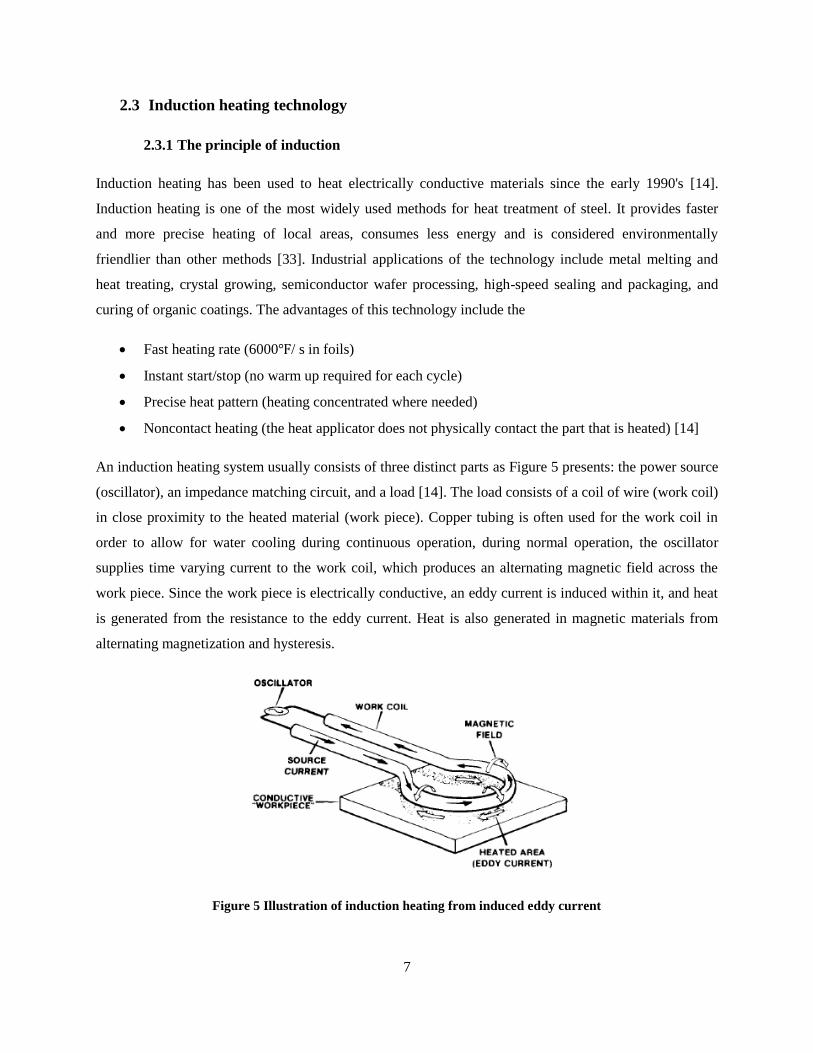
Inconel 718, a high strength, thermal resistant Nickel-based alloy presented in Table 1, has a wide range
of applications in the aircraft industries, e.g. aircraft gas turbines, stack gas reheaters, reciprocating
engines, etc. It maintains excellent mechanical properties and is corrosion resistant over a wide
temperature range (-423°to 1300°F) [1]. The superficial stress of the aerospace parts is mandatory to
achieve a certain fatigue life by Federal Aviation Administration regulations [FAA, 2005].
Table 1 Physical constant of Inconel 718
Grinding is one of the most popular methods of machining hard materials widely used to produce surfaces
of good dimensional accuracy and finish.[3] Because it is usually one of the final operations of the
technological process, properties of surface layer created in grinding influence directly the functional
properties of the work piece such as fatigue strength, abrasive and corrosion resistance, etc. On the other
hand, Inconel 718 family is one of the most difficult to cut materials because they are very stain rate
sensitive and readily work harden, and poor thermal conductivity, leading high cutting temperature at rake
face [37]. Figure 2 presents the precision grinding for complex parts as a final machining step.

4
Figure 2 Precision grinding process
Low residual stress after grinding is an important requirement for surface integrity of stress sensitive
components. If tensile residual stresses remain in the surface, the subsequent service life may be reduced
under stress corrosion or fatigue conditions. [4] Compressive stresses are generally beneficial to fatigue
life, creep life and resistance to stress corrosion cracking, whereas tensile residual stresses are usually
detrimental to these same properties. In summary, residual stresses in machining are produced as a
consequence of inhomogeneous plastic deformation induced by mechanical and thermal unit events
associated with the process of chip formation (cutting) and the interaction between the tool nose region
and the freshly machined work piece surface (squeezing). Plastic deformation due to forces parallel and
perpendicular to the surface produces compressive residual stresses, whereas plastic deformation as a
consequence of local heating shifts the balance towards tensile residual stresses. Phase transformations
can support the development of both compressive and tensile residual stresses depending on the relative
volume changes and the accompanying plastic deformations [4].
Figure 3 Residual stress employed by grinding effects
(a) Phase transformation; (b) Thermal expansion and contraction; (c) Plastic Deformation

5
Thermal expansion and contraction in the grinding process was the most significant factor in the
generation of tensile residual stresses. Cutting temperatures generally increased with cutting speed and
decreased with the increasing cooling efficiency of the cutting environment [31]. During grinding, high
temperatures are generated at the interface between the wheel and the work piece as well as in the work
sub-surface due to frictional heating and localized plastic deformation.[3]The problem of controlling
stress is transformed into the problem of controlling grinding temperature. [4] Experience indicates that
Tensile residual stresses are developed after the grinding temperature reaches a critical level at
approximately 200 which is hard to meet by regular coolant.
Various methods have so far been employed in order to improve fatigue strength, including optimization
of geometric design, stronger materials and surface processing such as shot peening[17]. Shot peening has
long been widely used as a low cost and simple method for increasing the fatigue strength of springs[24].
It is well known that shot peening a surface of a part or member creates a large compressive residual
stress on the surface. It is also well known that this compressive residual stress contributes to the
increased fatigue strength of the member. Shot peening can improve fatigue resistance by introducing a
compressive residual stress in the surface layers of the material, making the nucleation and propagation of
fatigue cracks more difficult [18]. However, shot peening cannot guarantee 100% compressive residual
stress and may damage the well finished surface.
A novel grinding technology is to be developed to generate compressive superficial stress to meet both of
the roughness and residual stress requirements.
2.2 Proposed technology
At the grinding zone, the thermal expansion of hotter material closer to the surface is partially constrained
by the cooler subsurface material. This generates compressive thermal stresses near the surface which, if
sufficiently big, cause plastic flow in compression. However during subsequent cooling, after the grinding
heat passes, the plastically deformed material tends to reduce the volume in comparison to the beneath
subsurface material, so the requirement of material continuity causes tensile stresses to develop near the
surface.
6
Grinding Wheel
Plastic
Deformation
Layer (Zone 2)
During Grinding:Plastic Deformation
Elastic Deformation
After Grinding:Plastic Deformation
Elastic Deformation
Final Stress
Distribution Copmpression
Tension
Mechanical Effect
Grinding WheelLayer Removed
(Zone 1)
During Grinding: Hot
Cold
Plastic Deformation
Elastic Deformation
After Grinding:
Cooling DownCold
Cold
Final Stress
Distribution Tension
Compression
Thermal Effect
Plastic
Deformation
Layer (Zone 2)Grinding Wheel
During Grinding:
After Grinding:
Cooling Down
Final Stress
Distribution
Compression
Improved Thermal Effect
Heat Affected
Layer (Zone 3)
Hot
Cold
Cold
Tension
Compression
Before Grinding:
Cold
Cold
Hot
Hot
Cold
Plastic Deformation
Elastic Deformation
Hot
Layer Removed
(Zone 1)Layer Removed
(Zone 1)
Plastic
Deformation
Layer (Zone 2)
(a) (b) (c)
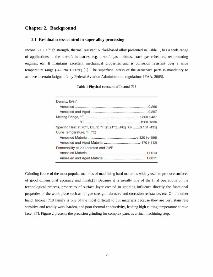
Figure 4 The different ways how the grinding force and the grinding heat affect the residual stress
(a) mechanical effect on the residual stress generation in the classic and proposed technology; (b) thermal effect
on the residual stress generation in the traditional technology; and (c) thermal effect on the residual stress generation
in the proposed technology.
In the technology, a ‘hot’ inner layer will be introduced in a controllable way before the grinding
process occurs and the general mechanism of residual stress generation [Figure 4 (a) and Figure 4(b)] is
changed during grinding process. As shown in Figure 4(c), the ‘hot’ layer exists before and during the
grinding process. Before the grinding wheel engaging with the workpiece, the subsurface layer is pre-
heated. This part of the work material experiences a higher temperature rise and intends to expand.
During the grinding process, the superficial layer experiences a higher temperature than the subsurface
layer, causing more severe plastic deformation and compressive stress than the subsurface layer. While
after the grinding wheel pass the workpiece, the workpiece surface is subjected to rapid cooling. But the
subsurface is also with a higher temperature. Both surface and subsurface material will be cooled
simultaneously at similar rates, which maintain the superficial residual stress distribution to the final
status.
7
2.3 Induction heating technology
2.3.1 The principle of induction
Induction heating has been used to heat electrically conductive materials since the early 1990's [14].
Induction heating is one of the most widely used methods for heat treatment of steel. It provides faster
and more precise heating of local areas, consumes less energy and is considered environmentally
friendlier than other methods [33]. Industrial applications of the technology include metal melting and
heat treating, crystal growing, semiconductor wafer processing, high-speed sealing and packaging, and
curing of organic coatings. The advantages of this technology include the
Fast heating rate (6000 / s in foils)
Instant start/stop (no warm up required for each cycle)
Precise heat pattern (heating concentrated where needed)
Noncontact heating (the heat applicator does not physically contact the part that is heated) [14]
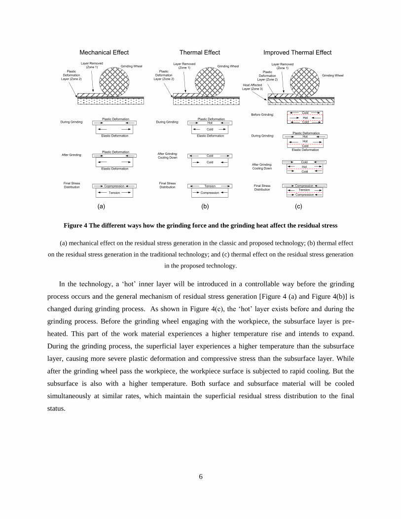
An induction heating system usually consists of three distinct parts as Figure 5 presents: the power source
(oscillator), an impedance matching circuit, and a load [14]. The load consists of a coil of wire (work coil)
in close proximity to the heated material (work piece). Copper tubing is often used for the work coil in
order to allow for water cooling during continuous operation, during normal operation, the oscillator
supplies time varying current to the work coil, which produces an alternating magnetic field across the
work piece. Since the work piece is electrically conductive, an eddy current is induced within it, and heat
is generated from the resistance to the eddy current. Heat is also generated in magnetic materials from
alternating magnetization and hysteresis.
Figure 5 Illustration of induction heating from induced eddy current

8
With regard to the fact that material properties change drastically with temperature variations during an
induction heating process and the difficulty in combining magnetic field and thermal analyses, analytical
methods are very difficult to implement. Therefore, a computer-aided numerical tool, by using the finite-
element method (FEM) is required to numerically model these coupled analyses, COMSOL Multiphysics
is chosen in thesis [38].
2.3.2 The mathematical modeling of the electromagnetic field
The technique of calculating electromagnetic field depends on the ability to solve Maxwell’s equations
[25]. For general time-varying electromagnetic fields, Maxwell’s equations in differential form can be
written as:
Ampere’s circuital law:
(1.1)
Faraday’s law of induction:
(1.2)
Gauss’s law for magnetism:
(1.3)
Gauss’s law:
(1.4)
where E is the electric field intensity, D is electric flux density, H is magnetic field intensity, B is the
magnetic flux density, J is conduction current density and is the electric charge density.
Maxwell’s equations not only have a purely mathematical meaning, they have a concrete physical
interpretation as well. Equation 1.1 says that the curl of H has always two sources: conductive (J) and
displacement currents. A magnetic field is produced whenever there are electric currents flowing in
surrounding objects. From equation 1.2, one can conclude that a time rate of change in magnetic flux
density B always produces the curling E field and induces currents in the surrounding area and therefore,
in other words it produces an electric field in the area where such changes take place. The minus sign in

9
equation 1.2 determines the direction of that induced electric field. This fundamental result can be applied
to any region in space.
The application of alternating voltage to the induction coil will result in the appearance of an alternating
current in the coil circuit. According to Eq. (1.1), an alternating coil current will produce in its
surrounding area an alternating magnetic field that will have same frequency as the source current. That
magnetic field’s strength depends on the current flowing in the induction coil, the coil geometry and the
distance from the coil. The changing magnetic field induces eddy currents in the work piece and in other
objects that are located near that coil. By Eq. (1.2), induced currents have the same frequency as the
source coil current; however, their direction is opposite that of the coil current. This is determined by the
minus sign in Eq. (1.2). According to Eq. (1.1), alternating eddy currents induced in the work piece
produce their own magnetic fields, which have opposite directions to the direction of the main magnetic
field of the coil. The total magnetic field of the induction coil is a result of the source magnetic field and
induced magnetic fields.
As one would expect from analysis of Eq. (1.1), there can be undesirable heating of tools, fasteners, or
other electrically conductive structures loaded near the induction coil.
In induction heating and heat treatment applications, an engineer should pay particular attention to such
simple relations as (1.3) and (1.4). The short notation of Eq. (1.3) has real significance in induction
heating and the heat treatment of electrically conductive body. To say the divergence of magnetic flux
density is zero is equivalent to say that B lines have no source points at which they originate or end; in
other words, B lines always form a continuous loop[25].
The above-described Maxwell’s equations are in indefinite form because the number of equations is less
than the number of unknowns. These equations become definite when the relations between the field
quantities are specified. The following constitutive relations are additional and hold true for a linear
isotropic medium.
(1.5)
(1.6)
(1.7)
where the parameters , and denote, respectively, the relative permittivity, relative magnetic
permeability, and electrical conductivity of the material; , where is electrical resistivity. and
are constants.
10
By taking Eq. 1.5 and 1.7 into account, Eq. 1 can be written as:
(1.8)
For most practical applications of the induction heating of metals, where the frequency of currents is less
than 10MHz, the induced conduction current density J is much greater than the displacement current
, so the last term on the right hand side of Eq. (1.8) can be neglected. Therefore it becomes:
(1.9)
After some vector algebra and using Eqs. (1.1), (1.2) and (1.6), it is possible to show that
(
)
(1.10)
Since the magnetic flux density B satisfies a zero divergence condition as Eq. (1.3), it can be expressed in
terms of a magnetic vector potential A as
(1.11)
And then, from Eq. (1.2) and Eq. (1.11), it follows that
(1.12)
Therefore, after integration, one can obtain
(1.13)
where is the electric scalar potential. Eq. (1.7) can be written as
(1.14)
where is the source current density in the induction coil.
Taking the material properties as being piece wise continuous and neglecting the hysteresis and magnetic
saturation it can be shown that
(1.15)

11
In induction heating problems, equation (1.15) can be solved assuming a sinusoidal time dependence of
the magnetic vector potential A and magnetic permeability values corresponding to the first harmonic of
the magnetic field intensity. With these assumptions the nonlinear electromagnetic equation can be solved
iteratively till the convergence to steady magnetic permeability values is reached [35].
2.3.3 The mathematical modeling of the thermal process
In general, the transient (time-dependent) heat transfer process in a metal workpiece can be described by
the Fourier equation:
(1.16)
where T is temperature, is the density of metal, c is the specific heat, k is the thermal conductivity of the
metal, and Q is the heat source density induced by eddy currents per unit time in a unit volume. This heat
source density is obtained by solving the electromagnetic problem.
Eq. (1.16) with suitable boundary and initial conditions, represents the three-dimensional temperature
distribution at any time and at any point in the work piece. The initial temperature condition refers to the
temperature profile within the workpiece at time t=0; therefore that condition is required only when
dealing with a transient heat transfer problem where the temperature is a function not only of the space
coordinates but also of time. The initial temperature distribution is usually uniform and corresponds to the
ambient temperature. In some cases, the initial temperature distribution is nonuniform due to the residual
heat after the previous technological process.
For most engineering induction heating problems, boundary conditions combine the heat losses due to
convection and radiation. In this case the boundary condition can be expressed as:
(
) (1.17)
where is the temperature gradient in a direction normal to the surface at point under consideration,
is the convection surface heat transfer coefficient, is the radiation heat loss coefficient, is the
surface loss and n denotes the normal to the boundary surface.
The Eq. (1.16) can be shown in Cartesian coordinates as:
(
)
(
)
(
) (1.18)

12
This equation with boundary condition Eq. (1.17) are most popular equations for mathematical modeling
of the heat transfer process in induction heating and heat treatment applications.
2.4 The design of coil and concentrator
2.4.1 Coil design
During induction heating, the relationship between time and temperature must be controlled exactly to
obtain a uniform temperature distribution over the workpiece to control the formation of the subsurface
heating layer. The coil design is very important to control the temperature accurately.
To design the coil for heating, there are several conditions should be kept in mind. The coil should be
coupled to the part as closely as feasible for maximum energy transfer. It is desirable that the largest
possible number of magnetic flux lines intersect the workpiece at the area to be heated. The denser the
flux at this point, the higher will be the current generated in the part. The greatest number of flux lines in
a solenoid coil is toward the center of the coil. The flux lines are concentrated inside the coil, providing
the maximum heating rate there. Because the flux is most concentrated close to the coil turns themselves
and decreases farther from them, the geometric center of the coil is a weak flux path. This effect is more
pronounced in high-frequency induction heating. At the point where the leads and coil join, the magnetic
field is weaker; therefore, the magnetic center of the inductor is not necessarily the geometric center. Due
to the impracticability of always centering the part in the work coil, the part should be offset slightly
toward this area [15].
In addition, the part should be rotated, if practical, to provide uniform exposure. The coil must be
designed to prevent cancellation of the magnetic field. Putting a loop in the inductor (coil at center) will
provide some inductance. The coil will then heat a conducting material inserted in the opening. The
design at the right provides added inductance and is more representative of good coil design [15].
Table 2 The coupling coefficient at different frequency

13
Because of the above principles, some coils can transfer power more readily to a load because of their
ability to concentrate magnetic flux in the area to be heated. Coupling efficiency is showed in Table 2
which is the fraction of energy delivered to the coil which is transferred to the workpiece.
There are kinds of coil designed as Figure 6 presents for different industry application, even for complex
parts [15].
Figure 6 The typical coil design for different application
2.4.2 Concentrator design
Flux concentrators are magnetic materials which are utilized to gather the flux field set up during
induction heating and thus to modify the resultant heating pattern.
Materials for flux concentrators are of two basic types: (1) packages of laminated silicon steel punchings
used at frequencies below 10k Hz and (2) ferrites or powdered iron combinations for higher frequencies,
including those in the radio-frequency range.

14
Flux concentrators, whether laminations or ferrites should be located directly in or on the coil. For
example, placement in the center of a pancake coil collapses the over-all field to provide a higher density
at the coil surface. In the same manner, insertion of a concentrator in a helical coil collapses the end flux
outside the coil center. Physical characteristic of the concentrators are presented in Table 3.
Table 3 Physical characteristic chart from Fluxtrol
15
Chapter 3. The modeling and simulation of the novel technology
3.1 Simulation process design
3.1.1 The simulation software
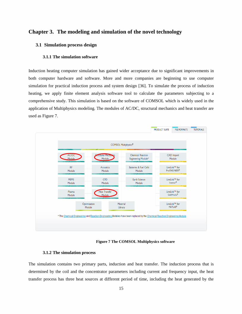
Induction heating computer simulation has gained wider acceptance due to significant improvements in
both computer hardware and software. More and more companies are beginning to use computer
simulation for practical induction process and system design [36]. To simulate the process of induction
heating, we apply finite element analysis software tool to calculate the parameters subjecting to a
comprehensive study. This simulation is based on the software of COMSOL which is widely used in the
application of Multiphysics modeling. The modules of AC/DC, structural mechanics and heat transfer are
used as Figure 7.
Figure 7 The COMSOL Multiphysics software
3.1.2 The simulation process
The simulation contains two primary parts, induction and heat transfer. The induction process that is
determined by the coil and the concentrator parameters including current and frequency input, the heat
transfer process has three heat sources at different period of time, including the heat generated by the
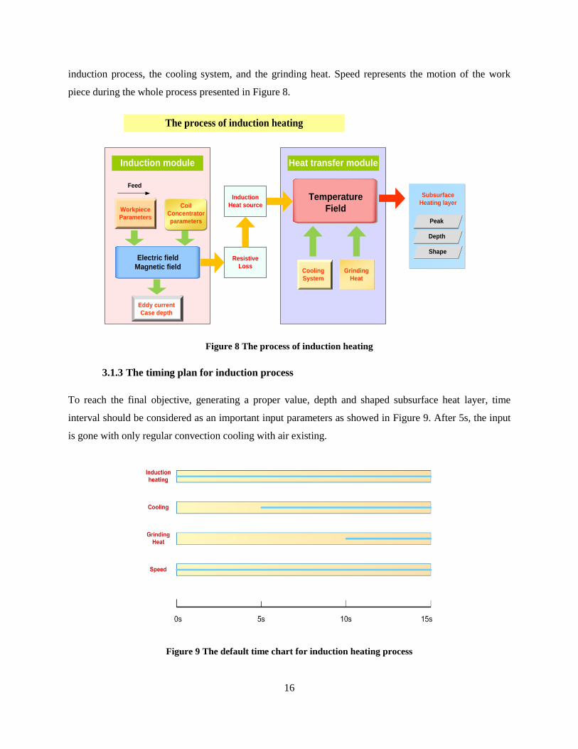
16
induction process, the cooling system, and the grinding heat. Speed represents the motion of the work
piece during the whole process presented in Figure 8.
Induction module Heat transfer module
The process of induction heating
Induction
Heat source
Resistive
Loss
Workpiece
Parameters
Electric field
Magnetic field
Coil
Concentrator
parameters
Eddy current
Case depth
Temperature
Field
Cooling
System
Grinding
Heat
Subsurface
Heating layer
Peak
Depth
Shape
Feed
Figure 8 The process of induction heating
3.1.3 The timing plan for induction process
To reach the final objective, generating a proper value, depth and shaped subsurface heat layer, time
interval should be considered as an important input parameters as showed in Figure 9. After 5s, the input
is gone with only regular convection cooling with air existing.
Figure 9 The default time chart for induction heating process
17
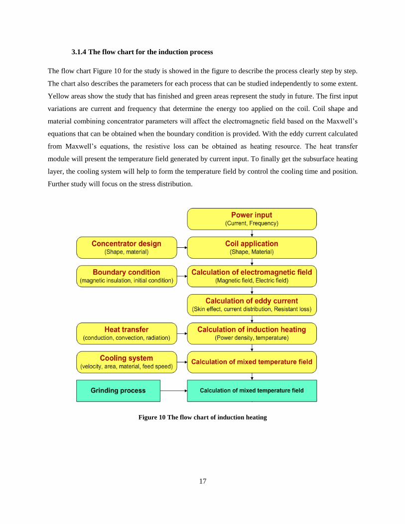
3.1.4 The flow chart for the induction process
The flow chart Figure 10 for the study is showed in the figure to describe the process clearly step by step.
The chart also describes the parameters for each process that can be studied independently to some extent.
Yellow areas show the study that has finished and green areas represent the study in future. The first input
variations are current and frequency that determine the energy too applied on the coil. Coil shape and
material combining concentrator parameters will affect the electromagnetic field based on the Maxwell’s
equations that can be obtained when the boundary condition is provided. With the eddy current calculated
from Maxwell’s equations, the resistive loss can be obtained as heating resource. The heat transfer
module will present the temperature field generated by current input. To finally get the subsurface heating
layer, the cooling system will help to form the temperature field by control the cooling time and position.
Further study will focus on the stress distribution.
Figure 10 The flow chart of induction heating

18
3.2 The simulation conditions
3.2.1 The geometry model design
To study the induction process, a 2D model is built as showed in Figure 11. 2D model is preferred to have
a better efficiency with the computer and the thickness is set to 100 mm. In the figure, A is the coil set to
the material of copper with concentrator outside that has special electric parameters, B is the workpiece
made of Inconel 718 that is prepared to grind marked with E, C represents the cooling system that has
convection heat transfer coefficient on it, D is the grinding contacting area with a width of 2mm, and F is
the air that plays a role in the propagation of electromagnetic field. The space around the elements is
assigned air parameters with a shape of circle of which center is the same with the coil center to keep the
electromagnetic lines closed.During the analysis, the position relationship for the elements in Figure 11 is
also studied, such as the gap between coil and workpiece, the gap between the coil and concentrator.
Cooling position is also studied.
Figure 11 The geometry model
Unit: mm, A: Coil, B: Workpiece, C:Cooling agent, D:Grinding heat flux, E: Concentrator
The meshing function provide by COMSOL is presented in Figure 12 in which the air area is meshed
with a large scale while the coil and workpiece is meshed with smaller elements that can be implemented
separated.
A
B
C D
E F

19
Figure 12 The meshing provided by COMSOL
The temperature profile inside the items depends on geometry configurations, the coupling of the samples
and material properties[32]. In this thesis we analyze the temperature inside the workpiece by varying
parameters, the current inside the coils, to obtain the subsurface heating layer.
3.2.2 The materials parameters
a) Coil parameters
Coil parameters are presented in Table 4. Coil and concentrator system should have its own cooling
system, so the thermal parameters are not considered in the simulation process. It was assumed that the
specimen structures were homogenized at 6003C and initially free of residual stresses [20]. The material
selected is brass. The temperature dependence of the magnetic permeability is usually neglected so that
the magnetic permeability and electric permittivity are assigned to 1 [26].
Table 4 Parameters of coil
Parameters Sign Value Unit
1 Magnetic permeability 1 H/m
2 Electric permittivity 1 F/m
3 Electric conductivity 5.95e7 S/m
4 Current J 400 A
5 Current density Js0 20000 A/m
6 Frequency f 100k Hz
20
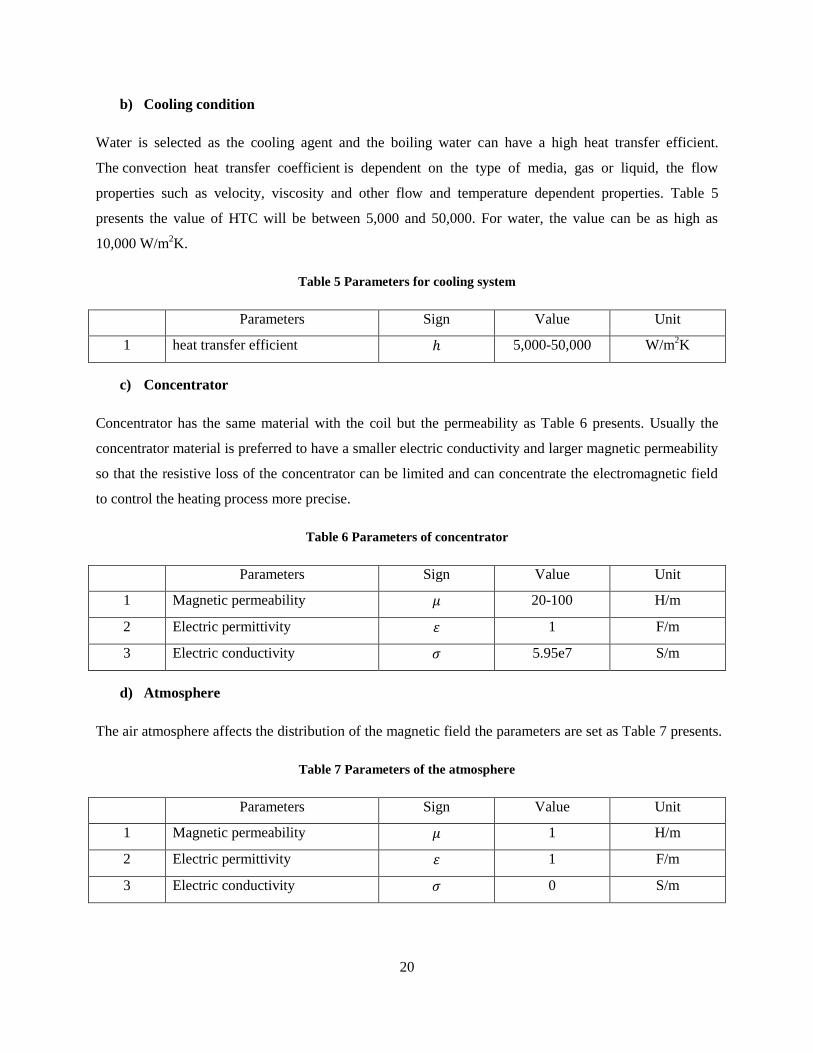
b) Cooling condition
Water is selected as the cooling agent and the boiling water can have a high heat transfer efficient.
The convection heat transfer coefficient is dependent on the type of media, gas or liquid, the flow
properties such as velocity, viscosity and other flow and temperature dependent properties. Table 5
presents the value of HTC will be between 5,000 and 50,000. For water, the value can be as high as
10,000 W/m2K.
Table 5 Parameters for cooling system
Parameters Sign Value Unit
1 heat transfer efficient 5,000-50,000 W/m2K
c) Concentrator
Concentrator has the same material with the coil but the permeability as Table 6 presents. Usually the
concentrator material is preferred to have a smaller electric conductivity and larger magnetic permeability
so that the resistive loss of the concentrator can be limited and can concentrate the electromagnetic field
to control the heating process more precise.
Table 6 Parameters of concentrator
Parameters Sign Value Unit
1 Magnetic permeability 20-100 H/m
2 Electric permittivity 1 F/m
3 Electric conductivity 5.95e7 S/m
d) Atmosphere
The air atmosphere affects the distribution of the magnetic field the parameters are set as Table 7 presents.
Table 7 Parameters of the atmosphere
Parameters Sign Value Unit
1 Magnetic permeability 1 H/m
2 Electric permittivity 1 F/m
3 Electric conductivity 0 S/m
21
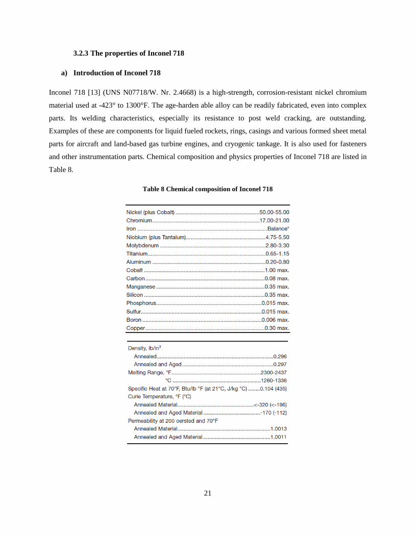
3.2.3 The properties of Inconel 718
a) Introduction of Inconel 718
Inconel 718 [13] (UNS N07718/W. Nr. 2.4668) is a high-strength, corrosion-resistant nickel chromium
material used at -423° to 1300°F. The age-harden able alloy can be readily fabricated, even into complex
parts. Its welding characteristics, especially its resistance to post weld cracking, are outstanding.
Examples of these are components for liquid fueled rockets, rings, casings and various formed sheet metal
parts for aircraft and land-based gas turbine engines, and cryogenic tankage. It is also used for fasteners
and other instrumentation parts. Chemical composition and physics properties of Inconel 718 are listed in
Table 8.
Table 8 Chemical composition of Inconel 718

22
b) The electromagnetic properties of Inconel 718
The properties of the Inconel 718 alloy are listed in Table 9, in which the temperature coefficient is used
for the calculation of the electric conductivity because it is temperature dependent.
Table 9 Parameters of the electromagnetic properties of Inconel 718
parameters sign Value Unit
1 Magnetic permeability 1 H/m
2 Electric permittivity 1 F/m
3 Electric resistive 1.754E-8
4 Temperature coefficient alpha 0.0039 K-1
The electric conductivity is varied by the temperature. =1/(r0*(1+alpha*(T-T0))) as Figure 13
Figure 13 Electric conductivity
(Unit S/m)

23
c) The heat transfer properties of Inconel 718
Thermal parameters are function of the temperature. During the process the heat capacity and thermal
conductivity are considered as Figure 14 and Figure 15.
Figure 14 Heat capacity
(Unit: J/(kg*K))
Figure 15 Thermal conductivity
(Unit: W/(w*K))

24
3.2.4 Grinding heat
Simplified as a heat flux as wide as 2mm and with a heat flux value input, it will contribute to the final
temperature field distribution. The right-angled triangle model is selected presented in The strength of the
heat source in a theoretical modeling should vary in the grinding zone and could be properly described by
a triangular profile with an adjustable apex to accommodate the effect of different grinding operations.
Inside a grinding zone there is usually much less coolant, and the coolant there may evaporate. Thus the
convection rate inside is generally lower [23]. In our model the heat flux is defined as Figure 16, a right-
angle triangle with a width of 2mm which is the contact area between grinding wheel and work piece.
The strength of the heat source in a theoretical modeling should vary in the grinding zone and could be
properly described by a triangular profile with an adjustable apex to accommodate the effect of different
grinding operations. Inside a grinding zone there is usually much less coolant, and the coolant there may
evaporate. Thus the convection rate inside is generally lower [23]. In our model the heat flux is defined as
Figure 16, a right-angle triangle with a width of 2mm which is the contact area between grinding wheel
and work piece. and the traditional heat flux will be around 1e7 as Table 10 presents [22].
Table 10 parameters for grinding heat
Parameters Sign Value Unit
1 Heat flux 1e7 W/m2
The strength of the heat source in a theoretical modeling should vary in the grinding zone and could be
properly described by a triangular profile with an adjustable apex to accommodate the effect of different
grinding operations. Inside a grinding zone there is usually much less coolant, and the coolant there may
evaporate. Thus the convection rate inside is generally lower [23]. In our model the heat flux is defined as
Figure 16, a right-angle triangle with a width of 2mm which is the contact area between grinding wheel
and work piece.
3.3 The operation parameters
The parameters that will be studied in the project are presented in Table 11 including the current input,
coil and concentrator properties and cooling system.

25
Table 11 The parameters to study
Chapter 4. Simulation result
The simulation of induction process can be divided into three steps, the electromagnetic process, the heat
transfer process and heat transfer combining the cooling system.
Each process can be studied independently. The requirement for induction is to generate a certain value
of resistive loss, which will be the main heat resource input of the heat transfer process. Based on the
resistive loss value, we can simulate the induction process by adjusting the parameters of the coil
Induction Module Parameter to study Output parameters
1 Current input
Current Electric field
Magnetic field
Case depth
Resistive loss
2 Frequency
3 Coil properties Relative permeability
4 Electric conductivity
5 Relative permittivity
6 Dimension
7 Shape
8 Distance from workpiece
9 Concentrator
properties
Relative permeability
10 Electric conductivity
11 Relative permittivity
12 Dimension
13 Shape
14 Gap between the concentrator and coil
15 Cooling system
Feed speed Temperature distribution
The highest temperature
The depth of the peak
Shape of heat layer
16 Cooling position
17 Cooling time
18 Cooling agent heat transfer coefficient
26
parameters and concentrators, besides the distance and shape information. On the other hand, the input of
current and frequency can be studied at the same time.
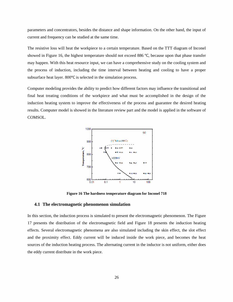
The resistive loss will heat the workpiece to a certain temperature. Based on the TTT diagram of Inconel
showed in Figure 16, the highest temperature should not exceed 886 , because upon that phase transfer
may happen. With this heat resource input, we can have a comprehensive study on the cooling system and
the process of induction, including the time interval between heating and cooling to have a proper
subsurface heat layer. 800 is selected in the simulation process.
Computer modeling provides the ability to predict how different factors may influence the transitional and
final heat treating conditions of the workpiece and what must be accomplished in the design of the
induction heating system to improve the effectiveness of the process and guarantee the desired heating
results. Computer model is showed in the literature review part and the model is applied in the software of
COMSOL.
Figure 16 The hardness temperature diagram for Inconel 718
4.1 The electromagnetic phenomenon simulation
In this section, the induction process is simulated to present the electromagnetic phenomenon. The Figure
17 presents the distribution of the electromagnetic field and Figure 18 presents the induction heating
effects. Several electromagnetic phenomena are also simulated including the skin effect, the slot effect
and the proximity effect. Eddy current will be induced inside the work piece, and becomes the heat
sources of the induction heating process. The alternating current in the inductor is not uniform, either does
the eddy current distribute in the work piece.

27
Figure 17 The distribution of the electromagnetic field
The effectiveness of the heating is related to the following items: 1) shape of the plate surface subjected to
the variable magnetic flux; 2) area of the region exposed to the magnetic flux; 3) position of the region
exposed to the magnetic flux with respect to the plate center[34].
In high-frequency induction heating, the induced current is usually not uniform throughout the workpiece
[38]. This heat sources nonuniformity causes a nonuniform temperature profile in the workpiece as Figure
18 presents. To obtain a high efficient heating effect, parameters should be well investigated. In this part,
the phenomenon is studied.
Figure 18 The temperature field with by induction heating process
4.1.1 Skin effect
When a direct current flows through a conductor that stands alone, the current distribution within the
conductor’s cross-section is uniform. However, when an alternating current flows through the same
conductor, the current distribution is not uniform. The maximum value of the current density will always
be located on the surface of the conductor and the current density will decrease from the surface of the
conductor toward its center. This phenomenon of nonuniform current distribution within the conductor
cross-section is called the skin effect, which always occurs when there is an alternating current. Therefore
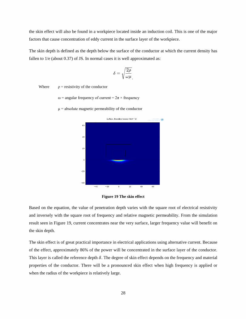
28
the skin effect will also be found in a workpiece located inside an induction coil. This is one of the major
factors that cause concentration of eddy current in the surface layer of the workpiece.
The skin depth is defined as the depth below the surface of the conductor at which the current density has
fallen to 1/e (about 0.37) of JS. In normal cases it is well approximated as:
.
Where ρ = resistivity of the conductor
ω = angular frequency of current = 2π × frequency
μ = absolute magnetic permeability of the conductor
Figure 19 The skin effect
Based on the equation, the value of penetration depth varies with the square root of electrical resistivity
and inversely with the square root of frequency and relative magnetic permeability. From the simulation
result seen in Figure 19, current concentrates near the very surface, larger frequency value will benefit on
the skin depth.
The skin effect is of great practical importance in electrical applications using alternative current. Because
of the effect, approximately 86% of the power will be concentrated in the surface layer of the conductor.
This layer is called the reference depth . The degree of skin effect depends on the frequency and material
properties of the conductor. There will be a pronounced skin effect when high frequency is applied or
when the radius of the workpiece is relatively large.

29
4.1.2 The distribution of AC in coil
The current distributed in the coil is not symmetrical but on the surface of coil due to the skin effect. The
induction process is sensitive with the distance between the coil and the workpiece, so the distribution of
the alternating current should be paied enough attention.
Figure 20 The distribution of the alterlating current inside the coil
The frequency is as low as 50Hz
The Figure 20 presents the alternating current distribution under the frequency of 50Hz which is relatively
low in the induction heating technology. The depth of the current could be calculated with same way of
skin depth. The Figure 21 presents the distribution of the current at a high frequency of 50k Hz in which
current almost becomes face current on the surface of the coil.
4.1.3 The proximity effect
The current of inside the coil will distribute close to the side of the workpiece surface due to the
proximity effect. When the current carrying conductor is placed to the workpiece, the current distribution
will concentrate in the areas facing each other when the direction of the current is different. Due to
Faraday’s law, eddy current induced within the workpiece have an opposite direction to that of the source
current of conductor. Figure 21 presents the current concentrates on the side of the surface of work piece,
the concentrator is disabled at this circumstance.
30
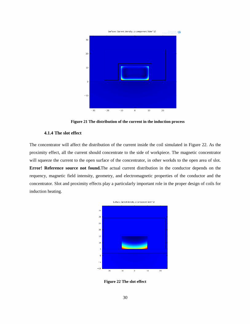
Figure 21 The distribution of the current in the induction process
4.1.4 The slot effect
The concentrator will affect the distribution of the current inside the coil simulated in Figure 22. As the
proximity effect, all the current should concentrate to the side of workpiece. The magnetic concentrator
will squeeze the current to the open surface of the concentrator, in other workds to the open area of slot.
Error! Reference source not found.The actual current distribution in the conductor depends on the
requency, magnetic field intensity, geometry, and electromagnetic properties of the conductor and the
concentrator. Slot and proximity effects play a particularly important role in the proper design of coils for
induction heating.
Figure 22 The slot effect

31
4.2 The electromagnetic analysis
4.2.1 The distribution of the magnetic field
The magnetic field is determined by the Maxwell’s equations. Based on the equations, the magnetic field
distribution is showed in Figure 23 and Figure 24 which indicate the magnetic field concentrates on the
surface area of the workpiece. The concentration finally causes the skin effect because the alternating
magnetic field generates the eddy current on the surface of the workpiece. Concentrator will benefit on
changing the distribution of the magnetic field limiting it focusing more on the surface of workpiece.
Figure 23 The magnetic field lines
From Figure 24, the magnetic field lines are concentrated near the surface of workpiece, the magnetic
field will generate current and result in the skin effect. Most of the magnetic induction line will get
through the surface of coil and the space between the coil and workpiece. The closer the coil to the
workpiece, the more magnetic induction line will get through. So the gap is also an important parameter
for induction heating process.

32
Figure 24 The magnetic field lines near the surface of work piece
4.2.2 The distribution of the current
The current exists near the surface of the workpiece as presented in Figure 25. As mentioned in 4.1, the
skin effect eventually determines current will concentrate near surface as a heating source.
Figure 25 The current distributes near the surface
Eddy current is the heat sources for the induction heating process, the concentration of eddy current will
determine the power input to a large extent. It helps to determine the current and frequency in the process.
4.2.3 The resistive loss
The resistive loss is the mainly energy for the heating process, it is calculated from the eddy current, so
the distribution seems similar with the current. These currents produce heat by Joule effect ( ). So the
resistive loss showed in Figure 26 is similar to the distribution of eddy current. The resistance of material

33
is specified by the Inconel 718 properties, so to control the energy input, the eddy current generation
should be studied systematically.
Figure 26 The distribution of the resistive loss
4.2.4 The effect of current on resistive loss
From the definition of skin effect, the current won’t change the skin depth, but as the increasing of the
current, the resistive loss increase significantly as Figure 27 presents. The increasing of the current input
will also result in the increasing of the eddy current inside the workpiece. To improve the heating speed,
improving the current input is an efficiency way, while the current needs to be controlled in certain value.
Figure 27 The effect of current on resistive loss
4.2.5 The effect of frequency on resistive loss and case depth
The frequency affects the resistive loss and determines the skin depth of workpiece as Figure 28 and
Figure 29 presents. The larger frequency will increase the resistive loss. When the frequency increases
0.00E+00
5.00E+09
1.00E+10
1.50E+10
2.00E+10
2.50E+10
3.00E+10
100 200 400 800
Re
sist
ive
loss
es
(W/m
3)
Current (A)
The effect of current on resistive loss

34
from 100kHz to 200kHz, the resistive loss is almost doubled. While when the frequency increases, the
case depth decreases which means the heat source can be deeper and will benefit on the subsurface
heating effect.
Figure 28 The effect of frequency on resistive loss
The skin depth can be as high as 5.5mm with a frequency value of 10k Hz. For induction heating process,
the frequency is large most time to keep energy input.
Figure 29 The effect of frequency on skin depth
0.00E+00
2.00E+09
4.00E+09
6.00E+09
8.00E+09
1.00E+10
1.20E+10
1.40E+10
1.60E+10
10 50 100 200
Re
sist
ive
loss
(W
/m3
)
The frequency (kHz)
The effect of frequency on resistive loss
0
1
2
3
4
5
6
10 50 100 200
Skin
de
pth
()m
m
The frequency (kHz)
The effect of frequency on skin depth

35
4.2.6 The effect of the distance between coil and workpiece on resistive loss
The distance of coil from workpiece will affect the heating efficiency. It’s obvious that the closer the coil
to the workpiece, the stronger the electromagnetic field is. At the same time, the induction current will be
larger in the workpiece as Figure 30presents.
Figure 30The effect gap between work piece and coil
Resistive loss of the workpiece varies with the gap, smaller gap will concentrate the power input well and
result in a better heating efficiency as Figure 31 presents.
Figure 31 The effect of gap between coil and workpiece on resistive loss
0.00E+00
2.00E+09
4.00E+09
6.00E+09
8.00E+09
1.00E+10
1.20E+10
0 5 10 15 20
The
re
sist
ive
loss
()W
/m3
The gap between coil and workpiece (mm)
The effect of gap between coil and workpiece on resistive loss

36
4.2.7 The effects of concentrator on induction heating
Concentrator is used to improve the induction heating in industry that helps concentrate the
electromagnetic lines forcing energy to a certain area to be heated. In Figure 32, the electromagnetic lines
distribute relatively uniform around the work piece, closer to the workpiece, the density is larger. While
in Figure 33, most of the electromagnetic lines gather inside the concentrator and the density of the lines
that also reflect the intensity of the electromagnetic filed becomes large.
Figure 32 Electromagnetic lines without concentrator
Simulation results also indicate that in same condition, the temperature of the workpiece increases from
406 to 561
Figure 33 Electromagnetic lines with concentrator
37
4.3 The thermal analysis
The objective of the research is to generate a subsurface heating layer as a preparation for the grinding
process. The induction heating will generate a temperature field inside the workpiece and the velocity
field is demanded by the process. And to avoid unnecessary factors during the novel grinding process, the
surface temperature should keep the same as usual at a relative low temperature. So the cooling system is
applied to the system following the induction heating process.
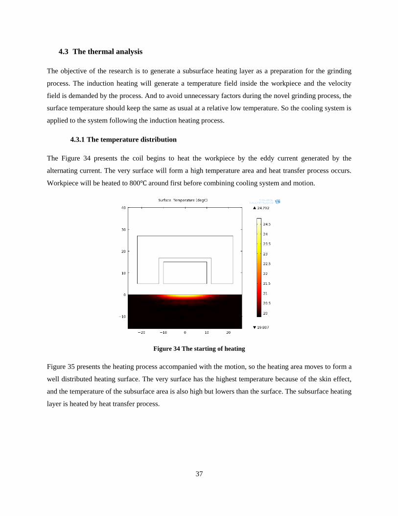
4.3.1 The temperature distribution
The Figure 34 presents the coil begins to heat the workpiece by the eddy current generated by the
alternating current. The very surface will form a high temperature area and heat transfer process occurs.
Workpiece will be heated to 800 around first before combining cooling system and motion.
Figure 34 The starting of heating
Figure 35 presents the heating process accompanied with the motion, so the heating area moves to form a
well distributed heating surface. The very surface has the highest temperature because of the skin effect,
and the temperature of the subsurface area is also high but lowers than the surface. The subsurface heating
layer is heated by heat transfer process.

38
Figure 35 The heating process with motion
Figure 36 presents after 10s, the cooling system is applied into the system, the surface of workpiece cools
down rapidly but the subsurface area is still hot because the rate of heat transfer is not as high as the
coolant. In this circumstance, at the certain position and certain time, the surface is cool but the
subsurface has a high temperature that can be used for further grinding to obtain superficial compressive
stress.
Figure 36 Forming of subsurface heating layer
The peak value and depth of the peak will be considered. The grinding process requires the surface of
workpiece with not too high temperature because it may become soft after heating. The surface after
cooling should be lower than 100 as preparation for grinding. Figure 37 presents the peak value of
330 and depth of 4.2mm.

39
Figure 37 Forming of subsurface heating layer
In the following sections, the effects of induction current input, frequency, coolant, cooling position and
feed are studied to have a comprehension understanding of the subsurface heating layer forming process.
A deeper subsurface heating layer with a higher temperature is preferred to affect the distribution of the
residual stress. To maintain the grinding process, the surface is required to limit the temperature so that
the surface will not become soft.
4.3.2 The effects of induction current input on peak value and depth
The increasing of the Max heating temperature will generate a higher temperature subsurface heating
layer and depth is a little deeper as Figure 38 presents. The corresponding currents input are I=730, 680,
630, 580A. f=10 kHz.
Figure 38 Subsurface heating layer with different induction heat input
0
50
100
150
200
250
300
0 5 10 15 20 25
Tem
pe
ratu
re /
C
Depth /mm
876 C
788 C
698 C
601 C

40
From Figure 38, the subsurface heating layer can be analysis, peak depth and peak temperature are
presented in Figure 39 and Figure 40. With a higher energy input, the peak depth can be lager, with a
current input of 730A, the peak can be as deep as 5mm with a temperature of 250 .
Figure 39 Peak depth of the subsurface heating layer with different induction heat input
Figure 40 Peak value of the subsurface heating layer with different induction heat input
0
1
2
3
4
5
6
500 600 700 800
0
50
100
150
200
250
300
500 600 700 800
Heating temperature
Pea
k d
epth
P
eak
tem
per
atu
re
Heating temperature

41
4.3.3 The effects of induction frequency input on peak value and depth
The increasing of the frequency will generate a shallower case depth but a higher temperature with same
current value input. With the same power input, smaller frequency is better for the formation of the
subsurface heating layer, comparing the Figure 41, Figure 42 and Figure 43.
F=10k, I=600A, Tmax
=590 , Skin depth=5.58mm
Figure 41 Temperature field with frequency input of 10kHz
In Figure 41, with a input current of 10kHz, 600A, before cooling, the temperature can be as high as
590 . The skin depth value is 5.58m.
F=5k, I=840A, Tmax=600 Skin depth=7.89mm
Figure 42 Temperature field with frequency input of 5kHz
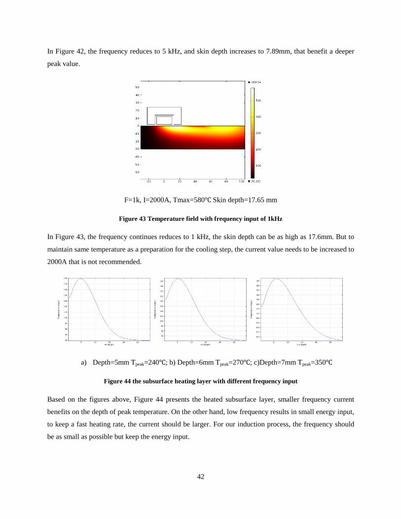
42
In Figure 42, the frequency reduces to 5 kHz, and skin depth increases to 7.89mm, that benefit a deeper
peak value.
F=1k, I=2000A, Tmax=580 Skin depth=17.65 mm
Figure 43 Temperature field with frequency input of 1kHz
In Figure 43, the frequency continues reduces to 1 kHz, the skin depth can be as high as 17.6mm. But to
maintain same temperature as a preparation for the cooling step, the current value needs to be increased to
2000A that is not recommended.
a) Depth=5mm Tpeak=240 ; b) Depth=6mm Tpeak=270 ; c)Depth=7mm Tpeak=350
Figure 44 the subsurface heating layer with different frequency input
Based on the figures above, Figure 44 presents the heated subsurface layer, smaller frequency current
benefits on the depth of peak temperature. On the other hand, low frequency results in small energy input,
to keep a fast heating rate, the current should be larger. For our induction process, the frequency should
be as small as possible but keep the energy input.

43
4.3.4 The effects of coolant heat transfer coefficient on peak value and depth
The heat transfer efficient should be exceed a certain value, or the surface temperature cannot reduce
under 100 , and with water as agent, the value cannot be more than 50000 W/m2K, usually the value is
around 10000 W/m2K. As the simulation result presents in Figure 45, high HTC coolant will take heat
away from the surface fast, the gradient between surface and subsurface layer will be larger. On the other
hand, it’s also important to limit the HTC because too high a rate of cooling leads to thermal stresses in
the product and consequently to cracks or fractures [19]. The peak value of the heating layer can be as
high as 270 with a HTC value of 50000W/m2K as Figure 46 presents.
Figure 45 Heating layer with different heat transfer efficient
As the simulation result presents in Figure 45, the heat transfer efficient don’t change the peak depth
much, so does the peak value. So the heating layer cannot be modified by the parameter of heat transfer
efficient.
Figure 46 Effect of heat transfer efficient on peak value
0
50
100
150
200
250
300
0 5 10 15 20 25
Tem
pe
ratu
re /
C
Depth /mm
5000 W/m2K
10000 W/m2K
20000 W/m2K
50000 W/m2K
150
170
190
210
230
250
270
290
0 10000 20000 30000 40000 50000
Heat transfer coefficient
Pea
k t
emp
erat
ure
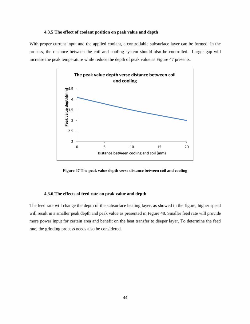
44
4.3.5 The effect of coolant position on peak value and depth
With proper current input and the applied coolant, a controllable subsurface layer can be formed. In the
process, the distance between the coil and cooling system should also be controlled. Larger gap will
increase the peak temperature while reduce the depth of peak value as Figure 47 presents.
Figure 47 The peak value depth verse distance between coil and cooling
4.3.6 The effects of feed rate on peak value and depth
The feed rate will change the depth of the subsurface heating layer, as showed in the figure, higher speed
will result in a smaller peak depth and peak value as presented in Figure 48. Smaller feed rate will provide
more power input for certain area and benefit on the heat transfer to deeper layer. To determine the feed
rate, the grinding process needs also be considered.
2
2.5
3
3.5
4
4.5
0 5 10 15 20
Pe
ak v
alu
e d
ep
th(m
m)
Distance between cooling and coil (mm)
The peak value depth verse distance between coil and cooling

45
Figure 48 The subsurface heating layer with different feed rate
4.4 Conclusion
The finite element analysis method is applied to simulate the process of the subsurface heating layer
generating. COMSOL Multphysics is selected to do the simulation. The induction phenomenon is
simulated with the software including the skin effect, proximity effect and slot effect.
Current, frequency, feed rate, coolant heat transfer coefficient is considered to regulate the subsurface
heating layer. Also the concentrator is used to concentrator the electromagnetic field and improves the
heating efficiency. More energy input or smaller feed rate will benefit on a higher peak value, and larger
coolant HTC and smaller feed rate will be used for a deeper layer.
With a feed rate of 0.01m/s, 10K heat transfer coefficient, 730A, 10 kHz current, subsurface with a peak
value around 250C, 4mm depth can be generated
0
50
100
150
200
250
300
350
0 5 10 15 20 25
Tem
pe
ratu
re /
C
Depth /mm
0.02 m/s
0.01 m/s
0.012 m/s
0.008 m/s
0.005 m/s

46
Chapter 5. Summery and future work
The numerical models of the subsurface heating technology are built in the thesis, and the models are
realized with the finite element analysis software COMSOL, and the effects of different parameters are
studied.
Skin effect, proximity effect and slot effect that will affect the performance of the induction heating.
Based on the effects, concentrator is applied to improve the heating efficiency. Proper thickness, smaller
gap, closer to workpiece is preferred for the concentrator to obtain the best heating function effect.
Subsurface heating layer is regulated by heating resource, feed rate, coolant and HTC. Heating effect is
determined directly by the current and frequency input which also determine the peak value of the. The
feed rate of the heat source and coolant HTC influence the depth of the heating layer.
The feed rate of the heat source should be well controlled to generate a moving temperature field. With
cooling system, the subsurface heating layer is generated. The shape and position of the subsurface is
determined by the temperature field generated by induction, the position of the cooling system, and the
time delay of the grinding process. With a feed rate of 0.01m/s, 10k W/m2s heat transfer coefficient,
730A, 10 kHz current input, subsurface with a peak value around 250C, 4mm depth can be generated
The stress distribution during grinding process will be studied as following research based on the
parameters from the induction heating process. The research will focus on the heat generating between the
wheel and the workpiece which will change the temperature field that have been formed combining the
induction and cooling process. To generate compressive stress is the objective of the research which is
determined mostly by the temperature field. Simulation based on the thermal stress model of COMSOL
will be applied to study the surface stress.
Suggestion for following experiment will be given based on the simulation result, including the
parameters of the coil and concentrator, also the current and frequency will be applied. To implement the
experiment well, the system should be well designed because the strict requirement of the delay time for
different procedure to create the surface stress.
47
Reference
[1] R.M. Arunachalam, M.A. Mannan, A.C. Spowage. Residual stress and surface roughness when facing age
hardened Inconel 718 with CBN and ceramic cutting tools. International Journal of Machine Tools &
Manufacture 44 (2004) 879–887
[2] Pei-lum Tso. Study on the grinding of Inconel 718. Journal of Materials Processing Technology 55 (1995)
421-426
[3] P.N. Moulik, H.T.Y. Yang, S. Chandrasekar. Simulation of thermal stresses due to grinding. International
Journal of Mechanical Sciences 43 (2001) 831-851
[4] X. Chena, W.B. Roweb, D.F. McCormack. Analysis of the transitional temperature for tensile residual
stress in grinding. Journal of Materials Processing Technology 107 (2000) 216±221
[5] Liang He, Kevin Rong. Project proposal.
[6] M. Rahman, W.K.H. Seah and T.T. Teo. The machinability of Incone1 718. Journal of materials
Processing teclmology 63 (1997) 199·204
[7] S. Malkin, C. Guo. Thermal Analysis of Grinding. Annals of the CIRP Vol. 56/2/2007
[8] H. D. Merchant, G. S. Murty, S. N. Bahadur, L.T. Dwivedi, Y. Ehrotra. Hardness-temperature relationships
in metals Journal of materials of (1973) 437 442
[9] W. Brian Rowe. Thermal analysis of high efficiency deep grinding. International journal of machine tools
& manufacture 41 (2001) 1–19
[10] K. Sadeghipour, J.A. Dopkin, K. Li. A computer aided finite element/ experimental analysis of induction
heating process of steel. Computers in Industry 28 (1996) 195-205
[11] C. Chaboudez, S. Clain, R. Glardon. Numerical modeling in induction heating for axisymmetric geometries.
IEEE transactions on. VOL. 33, NO. 1. Jan1997
[12] Bogdan W. KruszynÂski, Ryszard WoÂjcik. Residual stress in grinding. Journal of materials processing
technology 109 (2001) 254±257
[13] Inconel alloy 718. www.specialmetal.com
[14] Lawrence R. Egan and Edward P. Furlani. A computer simulation of an induction heating system. IEEE
transactions on. VOL. 21, NO. 5. Sep 1991
[15] Stanley zinn and S. L. Semiatin. Coil design and fabrication basic design and modifications. Heat treating,
June 1988
[16] H.K. Jung and C.G. Kang. An Induction heating process with coil design and solutions avoiding coarsening
phenomena of Al-6 Pct Si-3 Pct Cu-0.3 Pct Mg alloy for thixoforming. Metallurgical and materials
transactions A, Volume 30 November 1999—2967
[17] M. Kobayashi, T. Matsui , and Y. Murakamit. Mechanism of creation of compressive residual stress by
shot peening. International Journal of Fatigue, Vol. 20, No. 5, pp. 351–357, 1998
[18] M.A.S. Torres, H.J.C. Voorwald. An evaluation of shot peening, residual stress and stress relaxation on the
fatigue life of AISI 4340 steel. International Journal of Fatigue 24 (2002) 877–886
[19] M. Bamberger, B. Prinz. Determination of heat transfer coefficients during water cooling of metals.
Materials Science and Technology April 1986 Vol. 2

48
[20] S. Sen, B. Aksakal, A. Ozel. Transient and residual thermal stresses in quenched cylindrical bodies.
International Journal of Mechanical Sciences 42 (2000) 2013-2029
[21] Chen Ming, Li Xiaotian. Studies on the grinding characteristics of directionally solidified nickel-based
super alloy. International Journal of Mechanical Sciences 116 (2001) 165-169
[22] M. Mahdi, L. Zhang. Applied mechanics in grinding—VI. Residual stresses and surface hardening by
coupled thermo plasticity and phase transformation. International Journal of Machine Tools & Manufacture
38 (1998) 1289–1304
[23] M. Mahdi, L. Zhang. Applied mechanics in grinding –V. thermal residual stress. International Journal of
Machine Tools & Manufacture 37 (1997) 619–633
[24] Shengping Wang, Yongjun Li. Compressive residual stress introduced by shot peening. Journal of
Materials Processing Technology 73 (1998) 64–73
[25] K. Sadeghipour, J.A. Dopkin, K. Li. A computer aided finite element experimental analysis of
induction heating process of steel. Computers in Industry 28 (1996) 195-205
[26] Hiroki Kawaguchi, Masato Enokizono. Thermal and magnetic field analysis of induction heating problems.
Journal of Materials Processing Technology 161 (2005) 193–198
[27] A.D. Batako, W.B. Rowe, M.N. Morgan. Temperature measurement in high efficiency deep grinding.
International Journal of Machine Tools & Manufacture 45 (2005) 1231–1245
[28] M. Mahdi, L. Zhang. The finite element thermal analysis of grinding process by ADINA. Computers &
Struc/ures Vol. 56, No. Z/3, pp. 313-320, 1995
[29] Resource Guide for Induction Technology. www.fluxtrol.com.
[30] N. Biju, N. Ganesan. Frequency optimization for eddy current thermography. NDT&E International 42
(2009) 415–420
[31] E.-G. Ngl, D. W. Lee2, A. R. C. Sharmanl. High Speed Ball Nose End Milling of Inconel 718. Annals of
the ClRP Vol. 49/1/2000
[32] A. Della Savia1. Induction Heating of Samples in Vacuum Systems. Excerpt from the Proceedings of the
COMSOL Users Conference 2007 Grenoble
[33] Matej Kranjc, Anze Zupanic. Numerical analysis and thermography investigation of induction heating.
International Journal of Heat and Mass Transfer 53 (2010) 3585–3591
[34] Nikolaos Tsopelas, Nicolaos J. Siakavellas. Influence of Some Parameters on the Effectiveness of
Induction Heating. IEEE Transactions on magnetics, VOL. 44, NO. 12, Dec 2008
[35] F. Dughiero, M. Forzan. Solution of coupled electromagnetic and thermal problems in induction heating
applications. Computation in Electromagnetics, 10-12 April 1996
[36] Valentin Nemkov, Robert Goldstein. Computer simulation for fundamental study and practical solutions to
induction heating problems. The International Journal for Computation and Mathematics in Electrical and
Electronic Engineering Vol. 22 No. 1, 2003 pp. 181-191
[37] D. Dudzinski, A. Devillez. A review of developments towards dry and high speed machining of Inconel
718 alloy. International Journal of Machine Tools & Manufacture 44 (2004) 439–456
[38] Alexander Boadi, Yuji Tsuchida.Designing of suitable construction of high-frequency induction heating
coil by using finite-element method. IEEE Transactions on magnetics, Vol. 41, NO. 10, Oct 2005