Embed Size (px)
Citation preview

Nuclear Engineering and Design 51 (1979) 163-176 163 © North-Holland Publishing Company
3D ANALYSES OF SURFACE FLAWS IN THICK-WALLED REACTOR PRESSURE-VESSELS USING DISPLACEMENT-HYBRID FINITE ELEMENT METHOD *
Satya N. ATLURI and K. KATHIRESAN School of Engineering Science and Mechanics, Georgia Institute of Technology, Atlanta, Georgia 30332, USA
Received 18 May 1978
Solutions of stress intensity factors for external and internal unpressurized and pressurized surface cracks in internally pressurized thick-walled reactor pressure vessels are determined directly by a three-dimensional displacement-hybrid finite element method. The finite element method is based on a rigorous modified variational principle of the total potential energy, with arbitrary element interior displacements, interelement boundary displacements and element boundary tractions as variables. Special crack front elements, developed using the hybrid displacement model, which contain the proper square root and inverse square root variations of displacements and stresses, are used in this analysis and the three stress intensity factors, K I, KII and K m are solved directly along with the unknown nodal displacements. Stress intensity factor variations for pressurized and unpressurized semi-elliptical inner surface cracks in pressurized cylinders with crack aspect ratios of 0.2 and 1.0, crack depth to cylinder wall thickness ratios of 0.5 and 0.8 and outer to inner diameter ratios of 1.5 and 2.0, are presented. Also, for unpressurized outer surface cracks in pressurized cylinders, the solutions are presented for crack aspect ratios of 0.6 and 1.0, crack depth to cylinder wall thickness ratios of 0.4, 0.6 and 0.8, and outer to inner diameter ratio of 1.5.
1. Introduction
An important category of problems in thick-walled pressure vessels, especially those in nuclear reactor struc- tural applications, is the presence of surface flaws, mostly of semi-elliptical geometries, either inside of the pres- sure vessel or outside of the pressure vessel. Presence of such surface flaws elevates the stresses considerably, increasing the possibility of failure of the pressure vessel. Thus, the fracture analysis of such thick-walled pressure vessels is of utmost importance in assessing the structural integrety. To date, little work has been done to investi- gate such problems, although some investigators have obtained approximate solutions using, for instance, two- dimensional analogs of these problems. Clifton et al. [ 1 ] determined the critical stress-intensity factor for inter- nally pressurized thick-walled vessels. Kobayashi et al. [ 2 -4 ] investigated several inner and outer semicircular and semi-elliptical surface crack problems in internally pressurized and thermally shocked cylinders. Employing a con- ventional three-dimensional finite element program and virtual crack extension methods, Blackbrun and Hellen [5] obtained the solution for stress-intensity factors for surface cracks in blocks and cylinders. Recently Ayres [6] made an elastic three-dimensional analysis of semi-elliptical surface cracks subjected to thermal shocks and Hellen and Blackburn [7] calculated the stress-intensity factors, both using two- and three-dimensional conven- tional finite elements. Elastic analysis of radial crack in a circular ring was carried out by Bowie and Freeze [8].
It has been well established that the singularity in stresses and strains due to the presence of flaws or cracks in structural components has to be specially treated in the analysis and solution procedures. In most of the previous works mentioned, either a conventional finite element solution procedure, which proves to be more expensive and less accurate, or highly approximate solution procedures such as the alternating method [ 2 - 4 ] , with "correc- tion" of flat plate solutions by "curvature correction factors" estimated from two-dimensional analogs, are used.
* Parts of this paper were presented at the 3rd and 4th SMiRT Conferences, as papers L-7/3 and G-5/4, respectively.

164 S.N. Atluri, K. Kathiresan / 3D analysis of surface flaws in thicked-walled pressure vessels
NEAR - FIELD
r I
=1"1
t -DIRECTION TANeENTIAL TO CRACK BORDER
CRACK BORDER
Fig. 1. N o m e n c l a t u r e nea r c r a c k f r o n t .
When the crack is oblong and penetrates deeper into the thickness of the pressure vessel, a mere two-dimensional analog or a simple three-dimensional conventional finite element method may not be sufficient to assess the actual situation. In the solution procedures of Kobayashi [2-4] and Underwood [9], the effects of back surface on the crack were ignored and this may be very critical in the case of oblong cracks when the cracks penetrate deeper into the thickness of the pressure vessel wall. The solutions for stress intensity factors for inner and outer surface cracks in pressurized vessels are obtained in the present paper through a newly developed, embedded singularity, three-dimensional hybrid-displacement finite element procedure with no restrictive assumptions, and the results are presented here for various aspect ratios of the ellipse, inner to outer diameter ratios, and crack depth to thick- ness ratios. In the present procedure the stress-intensity factors are computed directly instead of computing them indirectly such as from the crack opening displacement method, etc.
2. Theoretical considerations of cracks in three dimensions
In the macroscopic (continuum) theories of fracture mechanics there are generally three types of problems: (a) the solution of the mechanics problem for the given geometry and applied loads to determine the "stress intensity factors" representing the severity of applied loads and corresponding to the conjectured modes of fracture such as brittle, ductile or quasi-ductile fracture; (b) experimental work to determine the resistance of material to fracture, quantified by parameters such as the "characteristic strength parameters"; and (c) development of an appropriate fracture criterion, which is nothing but the direct comparison of "characteristic strength parameters" to calcu- lated "stress-intensity factors" or a function of these stress-intensity factors. Consider an arbitrary-shaped flaw in an arbitrarily loaded three-dimensional structural component, as shown in fig. 1. The stress-intensity factors KI, Kn, and Kill, which may occur simultaneously in three-dimensional problems under arbitrary loading condi- tions, are defined as
Ki(t) = iim 2vr2-~Ozz(O = 0); Ku(t ) = lim ~ anz(O = 0); KUl = lim 2~v/2~-Otz(0 = 0). (1) t~'-'~ 0 r"-* 0 r'-'*O
Thus, KI, KII, and Kul may also vary from point to point along the crack border, defined by coordinate t. In terms of these factors, the asymptotic solution for displacements and stresses in the immediate neighborhood of a crack front have been shown [ 10] to be
Un 2 ~ cos~ 1 - 2 v ) + s i n 2 + KlI(2r)l12 ( l - v ) + c o s 2 + O ( r ) , (2a)

S.N. A tluri, K. Kathiresan / 3D analysis o f surface flaws in. thicked-walled pressure vessels 165
Klli(2r) 1/2 0 ut - s i n - + O ( r ) ,
ta,vq 2
-Kt(2r)l l2sin~.I2(1_ v)_ cos201 uz 2 ~ - ~
_ KI ( 0 On 4(2rrr)l/2 _3 cos-~
KI 0 ot - (2zrr)t/2 2v cos 2
Oz - 4(2zrr)l/2 cos
KIII 0 Otz (27rr)1/2 cos~+O(r ) ,
i(0 Ozn - 4(2rrr)l/2 sin ~ - sin + - -
KHI . 0 a , . - (2rrr)m sm-~ ÷ O(r),
KIl(2r)ll2cosO I(l _ 2v) _ sin2 Ol + O(r) 2#X/-~
50) KII ( O+ 5~) + O(r ) + cos -- 4(2nr)1/2 7 sin sin
KII 0 (27rr)1/2 2v sin~+ O(r) ,
KII (s inO_ sin 50) + O(r) 4(21rr) 1/2
KII (3 cos-02 + cos 50) + O(r) 4(2rrr) l/2
(2b)
(2c)
(3a)
(3b)
(3c)
(3d)
(3e)
(30
where # is the shear modulus, and v is the Poisson ratio. It can be shown [11] that using eqs. (2) and (3), the strain energy density [per unit volume, I¢ - S(O)/r] near the crack front may be written as
(16/~) S(O) - (al IK~ + 2al2KIKiI + a22K~i + aa3K~ii)flrr, (4) r
where ali = [(3 - 4v - cos 0)(1 + cos 0)] ;at2 = 2 sin 0 [cos 0 - (1 - 2v)] ;a22 = [4(1 - vX1 - cos 0) + (1 + cos 0) (3 c o s 0 - 1 ) ] ; a n d a 3 s = 4 .
It can be stated that the formulation of fracture criteria for general, mixed-mode, three-dimensional problems is still an open subject. Sih [11] has proposed such a fracture criterion based on the strain-energy-density concept, and may be stated as: (1) the crack grows in a direction, 0 = 0c, for which S(0) reaches a relative minimum, and (2) the crack growth begins when the value of S(KI, Ku, Kni) at 0 = 0 c reaches a critical value Sc, which is a ma- terial parameter.
Based on the fact that an appropriate fracture-criterion may be formulated and implemented when once the intensity factors Ki(t), Kn(t) and Kin(t) are known, the primary objective of this paper and computational frac- ture mechanics in general, is to accurately calculate the stress intensity factors for arbitrary-shaped flaws under general loading conditions.
3.1. The hybrid-displacement finite element model
In as much as the most commomly used compatible displacement finite element model with polynomial basis functions in each element cannot represent the asymptotic singular stress and strain fields in the vicinity of the crack boundary, an alternative finite element formulation is needed. In such a formulation one should be able to incorporate the exact asymptotic form of solution for singular stresses and strains in elements in a fixed region near the crack boundary (near-field), and use only regular polynomial-type basis functions in elements in the far field. Inter-element continuity of displacements and traction must also be maintained between the near-field ele- ments (with singular basis functions) and the far-field elements (with regular polynomial basis functions). One such formulation is the assumed displacement hybrid finite element model which has been previously used in two-

166 S.N. Atluri, K. Kathiresan / 3D analysis o f surface flaws in thicked-walled pressure vessels
dimensional problems of fracture-mechanics [ 12,13], and is extended in this paper to a three-dimensional formu- lation. We consider the solid to be discretized into a union of a finite number of finite-sized three-dimensional elements which have piecewise continuous boundaries at which neighboring elements join. We denote the sub- domain of each finite element by ~2 m and its boundary by ~2 m. We denote that portion of ~2 m which is com- mon to an adjacent element by Pm (inter-element boundary), that portion where tractions are prescribed by So,n, and that portion where displacements are prescribed by Sum. Thus, 3~2m = tom + So m + Sum. It may happen that, for certain elements which do not adjoin the overall boundary of g2, Sat -- Sul = 0 and hence, 8~ l = Or. While tra- versing along Pro, we arbitrarily denote the left-hand side vicinity (in the limit as Pm is approached) by superscript (+) and the right-hand side by a ( - ) . It is also worth noting that in an integral such as
f F(p) dp m
Om
to be considered below, each segment of the element boundary occurs twice because it is on the boundary of two adjacent domains, say ~'2 m and ~m+l .
With this notation suppose ~2m(m = 1 ..... n) be the elements immediately adjacent to the crack boundary as in fig. 1 (i. e. in the near field), and ~2 m (m = n + 1 ... . . M) be the elements in the far-field. Thus, singular-type strains and stresses will be assumed in the elements ~2rn(m = 1 ..... n) and regular-type strains will be assumed in elements ~rn~n = n + 1, ..., M). In constructing the general finite element model, based on assumed displacements, let ui in each ~'~m(m = 1 ..... n) be arbitrary (and this can include x/~-type functions in ~2m, m = 1 ... n) such that u~. v~ u 7 and ~ 4: TT, a priori, at Pro. Let eq = ½ (1Ai, j + Uj, i) and oi/= Eqktekt in each ~"~m. With these a priori con- ditions it can be shown [ 12-14] that the three-field variational principle governing the hybrid-displacement model is based on the modified potential energy functional
M
A(ui, r;~, ~,o) = Z3 { f ' [~EQklei/ekl-- ~ H i l a~2 f m=l
f2m Sam
P Ti(ui - -ffi) dS + J
Su m Ti(ui - ~ ) - f Tio (ui - ~,o) do } ,
Pm
(5)
where (1) u i are assumed displacements inside ~2m, (2) "ffio are independently assumed displacements on Pro, and are common to elements adjoining at Pro, and (3) Tip are Lagrange multipliers, assumed independent for each ele- ment on its boundary. The equation 8A = 0 with respect to variations in ui, Tip and "ffio can be shown to lead to the following Euler equations and boundary conditions: (a) equilibrium equation, oiL/+ Fi = 0 in ~2m; (b) trac- tion condition oiinj = Ti = Ti on Sore, (c) inter-element displacement continuity condition u~ = u[ = "ffio at Pm ; (d) inter-element traction equilibrium condition ~ = 7SYio = TFo = 77/on Pro; and (e) the displacement condition ui = ffi on Sum. The discrete approximations for each of the abive field variables can be assumed as follows:
(i) near field elements: ~'2m(m = 1 . . .n)
{Ui}----[URI{fl} +[Us ] K n ; {if/o} =[Ls]{q}; {Tio} = [ R s ] { a } ; (6) tKin)
(ii) far-field elements: ~m(rn = n + 1...M)
{ui} = [UR]{/3} ; {~iO} = [LIIq} ; {Tio} = [R]{a} . (7)
In the above [UR] are arbitrary polynomial functions, [Us] are asymptotically correct near-field solution func- tions as given by eq. (2); [Ls] are interpolates for boundary displacements of near-field elements in terms of ele- ment generalized displacement coordinates { q} at nodes on the boundary; [Rs] are arbitrary basis functions for boundary tractions on the near-field element; and similar interpretations are given for [UR], [L], and [R] perti- nent to the far-field element.

S.N. Atluri, K. Kathiresan / 319 analysis o f surface flaws in thicked-walled pressure vessels 167
It can be shown [ 15] that for the successful impelmentation of this finite element model the number of/3's in eqs. (6) and (7) should, in general, be greater than or at least equal to the number of t~'s, plus the number of rigid body modes for each element. It is also shown [ 12,13] that considerable numerical simplification would arise if number of/3's is equzd to the number of t~'s plus the number of rigid body modes for each element, and this con- dition is satisfied in the present formulation. By using eqs. (6) and (7) in eq. (5), eliminating ct's and/Ts for each element in terms of element nodal displacements, and noting the connectivity of nodal displacements of neighbor- ing elements, the functional in eq. (5) can be expressed as a function of independent global generalized displace- ments q* and the stress intensity factor vector K. The variation of A(q*, K) leads to the final algebraic equations, as shown in refs. [12,14], of the form
i K2 Ka _1 [ K Q2
from which q* and the stress-intensity factors K are directly solved for.
3. 2. Geometry o f the f ini te e lements
The geometrical shape of the element in Cartesian coordinates is a general "brick" element with six quadratic- ally curved surfaces and with twenty nodes, as shown in fig. 2a. I f x , y , z are Cartesian coordinates, we introduce curvilinear coordinates ~, r/, ~'(-1 < ~, r/, ~ < + 1) such that the relation between the two coordinates is given by
2 0 20 20
x = ~ N i (~ , r l , ~ ) x i ; y = ~ N i ( ~ , r l , ~ ) y i ; z = ~ N i ( ~ , ~ , ~ ) z i , (10) i=1 i=1 i=1
where (xi,Yi, Zi) are the Cartesian coordinates of the ith node (i = 1,20) of the element. The form of the functions Ni can readily be obtained from the well.known "isoparametric" element theory of
Zienkiewicz et al. The Jacobian of the coordinate transformation implied in eq. (10) is defined as
_ Fa(x, ,z)l [J] La(~, r~, ~')I " (11)
With the displacements u (x-direction), v (y-direction), and w (z-direction) as degrees-of-freedom at each node, the present element has 60 kinematic degrees-of-freedom.
In the subsequent sections the assumptions for ui, Tip and ~/p mentioned in sect. 3.1 are given only for the so- called "singular" elements near the crack boundary, for want of space. The construction of these singular elements
[ ~ X " "b"
|
1_9 T 18 17,37,57 7j b 12..,,,'~H *, = I 1 ~ -
o11.--,, , ,
FRONT placements in Cartes ian
Directions
Fig. 2. (a) Three-dimensional mapping. (b) Nodal displacements (cartesian).

168 S.N. Atluri, K. Kathiresan / 3D analysis of surface flaws in thicked-walled pressure vessels
with embedded singularities, is the crux of the problem; however, by omitting all the singular functions in the field variables and choosing appropriate regular functions to replace them, the "regular" elements for use in the far-field can easily be constructed [14].
3.3. Element-interior displacement field (singular element)
For a near-field ("singular") element, the [UR] {/3} part of the element displacement field {ui} as in eq. (6) is assumed as
//R ---/31 x +/32Y q- /33 Z + /34~J7/ +/357/~" +/36~'~ + ~7~ 2 + /3s'T~ 2 +/39~ 2 "l" /310~ 3 + /311 ~7~ 2 + /~121~ "2 + /313~j2n + /314"r/3
"l"/315~ 4 -I-/316~2~ " "l- /317~2~ "2 + /318~ "3 + /~19~7/~" + r igid b o d y m o d e s ,
I~R =/32 x +/320Y +/321Z +/322~7/ +/3237/~" at. /324~ + /325~ 2 + /3267/2 "1"/327~ "2 "l" J~28~ 3 "1"/329~7/2 ar/3307/4 + ~31~27/
+/3327/3 +/3337/~ "2 +/334~2r/2 +/33s7/2~ " +/336~ "3 +/337~7/~ + rigid body modes,
WR =/33 x +/321Y +/338 Z +/339~7/ +/3407/~" +/341~'~ +/342~ 2 +/3437/2 +/344~ "2 +/345~ 3 "1-/346~ "4 + /347~ "2 +/3487/2~ "2
+/3497/3 +/3sor/~ "2 +/3s1~2~ " +/3527/2~ " +/3s3~ "3 +/3s4~r/~" + rigid body modes. (12)
It is to be noted here that the terms corresponding to/31,/32,/33,/320,/321 and 13as are assumed in terms of Caresian coordinates to separate the rigid body modes completely. Thus, a total of 60 polynomial basis functions are assumed for the displacements, out of which 54 produce strains and the other 6 are rigid body modes. Care has been exercised to see that even the limiting cases, any of the 54 "straining modes" do not degenerate to rigid body modes. For the "singular" element the asymptotically correct solution as given in eq. (2) is assumed in addition, as shown in eq. (6), with the stress-intensity factors being used directly as undetermined parameters. By properly evaluating the Cartesian derivatives of the displacements given in eq. (12), the element strains are evaluated. Upon substitution for the total displacements, the element strain energy can be written as
f ½ Ei/klei/ekl d a - 1 / R R + ~ ~S.S R S [Ei/ktei/ekt ~ijklCijekl + 2Ei/kteij ekt ] d~ , Vim ~m
(13)
where the superscript R and S refer to "regular" and "singular", respectively. It can be seen that the second into- grand above has a 1/r singularity, whereas the third integrand has a l/x/7 singularity. However, since the asymp- totic displacement field u s in eq. (2) corresponds to an equilibrium solution, one can, upon application of the divergence theorem write,
S S da = f a S f s R , Eiikleiiektd~2= f T~iu R dS. (14a, b) I2 m I2 m ~2rn ~$2m
Thus, since ~ has a 1/~-variation and u s has a ~ variation, it can be seen that the r.h.s, integrand in eq. (14a) is free of singularities, whereas the r.hs. integrand in eq. (14b) has a "milder" 1/v~singularity. This facilitates accurate numerical computations.
3.4. Element boundary displacements (singular element)
As discussed in sect. 3.1, the boundary displacement ~ia should be common at Pm for neighboring elements. This is accomplished by interpolating for ~ia on a segment of am in terms of the nodal displacement coordinates on the particular segment of Pm only. Thus, considering the singular element such as ABCDEFGH in fig. (2b), the following boundary displacements are assumed.

S.N. Atluri, K. Kathiresan / 3D analysis of surface flaws in thicked-walled pressure vessels 169
3.4.1. Face ABFE (~ = - 1 )
u =ao + a l v a + a2r/+a3r+aaT12 +asvC~ + a 6 r r / + aTx/~ 2 , (15)
where r is the radius (dimensional) measured normal to the crack boundary. It can thus be seen that the displace- ments on face ABFE (plane of the crack) has the asymptotically correct X/7 variation. The parameters (a0, 41 ..... a7) are determined uniquely in terms of the relevant u-displacement coordinates on ABFE, namely ql, q2, q3, q9, qlo, q13, q 14, q ls (see fig. 2b). Thus, this boundary displacement would be the same for two singular elements joining at face ABFE. Similar interpolates are used for the other two displacements, v and w.
3.4.2. Face CDHG (~ = +1) Since this face is remote from the crack boundary, the displacements on this segment of the boundary can be
regular polynomials. Thus, for instance, the u-displacement on this face is interpolated uniquely in terms of the relevant nodal displacements q s, q6, q T, q 11, q12, q 17, q l a, q 19, as
u = qs( 1+ ~)(1 - r/)(~ - n - 1)/4 + q6(1 - ~2)(1 - rl)/2 + qT(1 - ~)(1 - r/)(-~ - n - 1)/4 + q~ 1(1 + ~)(1 - 77 2)
/2 + q12(1 - ~)(1 - r~2)/2 + q17(1 + ~)(1 + rT)(~ + r / - 1)/4 + qls(1 - ~2)(1 + r/)/2 + q19(1 - - ~)(1 + 7)
X ( - ~ + 7/+ 1)/4. (16)
Identical interpolates are used for v and w in terms of the respective nodal generalized coordinates. Eq. (16) repre- sents a unique quadratic interpolation for displacements u, v, and w on face CDHG and hence is automatically compatible with the boundary displacements of regular (far-field element) that adjoins the present singular element at surface CDGH.
3.4.3. Faces ABCD and EFGH (7? = - 1 and +1)
On these faces, which are perpendicular to the crack front, the asymptotic solution for displacements indicates not only a x/~ variation, but also a rapid variation with 0. To reflect this, for instance, the displacements on face ABCD are assumed as
u = ao + al~ + a2~ + aar + a4Vrrsin I 0(2 - 2v - cos 2 I 0) + asx/r cos I 0(1 - 2v - sin 2 1 0)
+ a6x/rcos I 0(1 - 2v + sin 2 1 0) + aTx/~sin ½ 0(2 - 2v + cos 2 -~ 0 ) , (17)
and identical displacements v and w, with (ao...aT) above, being replaced by (bo ... bT) and (Co ... c7), respectively. The parameters (ao ... 47) are uniquely found from ( q l - q s ) ; (bo ... bT) are found from (q21-q2s); and (Co ... c7) are found from (q41--q4s). An interpolate similar to that in eq. (17) is likewise used for each of the three displace- ments on face EFGH. It is clear that when other "singular" elements adjoin the present element at faces ABCD and EFGH, the inter-element displacements are compatible.
3.4.4. Face ADHE (~ = - 1 )
Similar to the interpolate on face ABFE, we assume
u = ao + a lX/~+ a2r7 + a3r + a4~/2 + asN/-rO + a6ro + aTx/~ 2 , (18)
where the constants (So ... aT) are evaluated in terms of (ql, qT, qs, qg, q12, qla, q19 and q20). Similar interpolates for v and w are assumed.
3.4.5. Face BCGH (~ = +1)
Similar to that on face CDHG, the interpolate for u is
u = q a ( 1 - r/)(1 - ~ ' ) ( - r / - ~" - 1 ) / 4 + q 4 ( l - ~'2)(1 - r / ) / 2 + q s ( 1 - r /X1 + ~ ' ) ( - r / + ~" - 1 ) / 4 + q l o ( 1 - r f l X 1 - ~')

170 S.N. Atluri, K. Kathiresan / 3D analysis o f surface flaws in thicked-walled pressure vessels
/2+q11(1- r /2 ) ( l+~ ' ) /2+q , s ( l+77) (1 ~ ' ) ( r / - ~ ' - l ) / 4 + q , 6 ( 1 - ~ ' 2 ) ( l + r / ) / 2
+q,7(1 +77)(1 + ~')(r/+ ~ ' - 1)/4.
Similar interpolates for v and w are assumed.
(19)
3.5. Element boundary tractions (singular element)
In this regard, we first note one of the relevant boundary conditions of the present variational principle, which states that the boundary tractions generated by the assumed element-interior displacements ui must match the independently assumed boundary tractions Tip at am and further that (Tip) + = Tip. This can be states precisely as
1 [giikl(Uk, l + Ul, k)n / ]+ = ZT.p = T~-ip = 1 [Eijkl(Uk, l + Ul, k ) n / ] - . (20)
Thus, since the assumed ui include a Xff-variation for the singular element, the boundary tractions generated by these ui would have a 1/V~-variation. Thus, it can be seen that for numerical accuracy the assumed tractions Tip for the singular element must also contain a 1/x/Tbehavior (from a purely mathematical point of view when Tip are Lagrange multipliers, this condition is not immediately apparent). Since the displacement field ui in addition to satisfying eq. (20) is also forced to satisfy the equilibrium equations through the variational principle, it can be seen that the better accuracy in the formulation is achieved if the assumed Tip are obtained from a (hypothetical) equilibrated stress field. Such a stress field can be obtained from the three-dimensional stress functions. To this end, we introduce the Beltrami stress function representation for stresses:
02X3 02X2 B2~l . OzXl +__02X3 _ 02t~2 . =__02X2 + B2XI _ 02~3 . Ox = ~ - + Oz 2 ayOz ' cry = Oz 2 Ox 2 OzOx ' crz Ox 2 Oy 2 OxBy '
B2XI 1 B // Or.b1 B~b2 _ - t + ÷B 31;crzx B2×2 +IL(O , t cryz = - Byb~z + -2 Bx - 8x By Bz ] OzBx 2 By \ Sx By Oz / '
B2X3 + 1 B (Bq.q +O~2 8~3] (21) crxy -- OxOy 2 O--z \ bx -Oy - 8z ] '
where (X1, X2 and XB) are Maxwell's stress functions, and (~bx, ~b2 and ~b3) are Morera's stress functions. For simpli- city, we present here only the stress function assumptions based on Maxwell's representation. Since the tractions generated from the above stress field have to be evaluated on the faces of the singular element, it is convenient to assume the stress function in terms of curvilinear coordinates ~, r/, and ~'. For reasons discussed in sect. 3.1, the three stress-functions (X, X2 and X3 ) were assumed with a total of 54 undetermined parameters in them. Out of these, 51 basis functions were of regular polynomial nature and the other 3 had a 1/Xff variation in them. Each of the 54 basis functions in the three stress-function assumptions should be such that it does not produce a stress tensor that is linearly dependent on the stress tensor produced by the other 53 basis functions. Another necessary condition in the proper choice of these stress functions is shown in [14] to be that the matrix [P1] represented in the scalar
[ ]~]T[P1]{a } = f [[JIT[uRIT[Rs]{Ot } ds (22)
a~rn
(where a are parameters in boundary tractions { Tit, } = [Rs]{ a} ) be non-singular. Thus, considerable care had to be exercised in properly choosing the stress function below such that they produce the needed stress modes, and these are given below:
X1 = OL1TI 2 + a2?/~" + O/3~'F/2 + Ot4~ "2 + O~s'F/~ "2 -F 0(6T'/2~ " + O/7~j'O~ + as'F/3~ "2 + O/9~jTI2~ " + 0~10~TI~ "2 + O~ 11T'/3~ " +Oll 2 ~ "3
+ Od13~ 3 + 0/14~2~ 2 +Oll 5'02~ 2 + Odl6~j2~ "2 + 0/17~4~ " ,

S.N. Atluri, K. Kathiresan / 3D analysis of surface flaws in thicked-walled pressure vessels 171
×2 = a l s t 2 + a 1 9 ~ + a2on~ 2 + a21~2n + a22~2~ + a 2 3 ~ 2 + '~'24~n~" + a2s~2~ 3 + a26~n~ 2 + a27~2n~ + ~ 2 s ~ 3
+ ~29~3~ " + a3o/j3r/+ ~3~r~2~ "2 + ~ 3 2 ~ "~ + ~ r / 2 + a 3 4 ~ ,
X3 = 0d35~ 2 -I- 0~36~ -I- 0/37~2~ -1- 0~38~2~ -I- 0 /39~ 2 + 0~0~2~ -1- o t41~ ~ -I- ~.42~3~ 2 -I- 0d43~2~ " q- 0~44~ 2 ~'-I- 0/45~3~
-I- 0~46~ 3 + 12~47~/3~ " + 0~48~2~ 2 Jr ~49~2~ 2 + 0~50T/2~ 2 + 0/51~4T/ . (23)
Setting, for convenience, (xt =x, x2 =y, x3 =z; and ~t = ~, ~2 = r/, ~3 = ~'), one can write
a2XIc _ OXk a2x m a2xk ox m ~Xn - - + - - (k = 1, 2, 3) ( 2 4 )
a~ia~, aXm a~ia,~i OXmOXn a~i a~j and calculate the stresses oij according to eq.(21), from which the boundary tractions are derived as Tip =oijn j. The remaining three traction modes Tip are assumed from the singular stress field given in eq. (3) wherein (KI, KH, and KII0 are replaced by cts~, t~s~, and t~s4, respectively.
The above three field functions, namely element interior displacements, boundary displacements and the bound- ary tractions, are the modified and improved versions, compared to those given in ref. [16].
4. Resu l t s a n d d i scuss ions
Some of the basic results of the "singular element" developed by the present hybrid-displacement finite element method can be found in ref. [16]. The developed "singular elements" were used successfully to analyze several three-dimensional fracture problems like surface flaws in thin plates, corner cracks emanating from holes in plates and surface flaws in pressure vessels [17-19]. In what follows a brief description of the results and discussions of several reactor pressure vessel surface flaw problems are given.
Fig. 3 gives the geometry of the internally pressurized thick-walled cylinder with semi-elliptical inner and outer surface cracks. The Poisson's ratio of the material is assumed to be 0.3. The length o f the cylinder is assumed to be such that L/2a (and L/Re)/> 3 for the t'mite element solution. Stresses Ozz, corresponding to the plane strain con-
1,'- 0 .3
RONT
NO. o f \ \~ \ \ \ \ ~ . ~ f ~ i m R i T - - ~ / NO. of Elem. = 156 D.O.F. - 2 6 7 0
~- CRACK FRONT
Fig. 3. Inner and outer semi-elliptical cracks in a pressurized cylinder (left).
Fig. 4. Finite element breakdown for inner and outer crack problems (right).

172 S.N. Atluri, K. Kathiresan / 3D analysis o f surface flaws in thicked-walled pressure vessels
dition (Ozz = --P(ORR -I- Otth0)) (where R and ¢ are the polar coordinates in the cross section of the cylinder) were imposed on the faces of the cylinder to account for the end condition of the probelm. When the crack is at the inner surface of the pressure vessel, unpressurized as well as pressurized cracks are considered. The finite element breakdowns of the cylinder with inner and outer cracks are given in fig. 4. Only one-fourth of the cylinder needs to be modeled because of symmetry. The breakdown has 156 elements and 2670 total number of degrees-of-free- dom.
4.1. Deep inner semi-circular f l aw
The solution of the variation of the stress-intensity factor for an unpressurized, deep, inner semicircular surface flaw with geometric parameters b/a = 1.0, b / ( R o - Ri) = 0.8, and R o / R i = 2 is given in fig. 5. The solution of the stress-intensity factor is normalized by the closed form solution of a completely embedded circular flaw in an infi- nite solid, the faces of which are acted on by a uniform pressure, o0, equal to the hoop stress at the inner face of the cylinder due internal pressure, p = Pi. Thus, the value of Oo is equal to pi{Ro/Ri ) 2 + l } / { ( R o / R i ) 2 - 1}. The solution in fig. 5 thus represents the actual stress-intensity factor values along the crack front but for a constant. The solution for a nearly identical problem with geometric parameters b/a = 0.98, b/(Ro - Ri) = 0.8 and R o / R i = 2.0, estimated by Kobayashi et al. [2-4] is also given in fig. 5. As can be seen in the figure, the solution obtained from the two-dimensional analog with curvature correction factors by Kobayashi et al. correlates excellently with the present solution. As the two solutions differ by about 5% it can be stated that the solution procedure adopted by Kobayashi et al. may be used with reasonable engineering confidence and judgement for obtaining the values of stress-intensity factors for surface flaw problems in pressure vessels. In the present deep semi-circular surface crack problem, the stress-intensity factor is maximum at the point where the crack meets the inner surface of the cylin- der (0 = 0 °) and the stress-intensity factor decreases with increasing 0 and the variation has a slight dip near 0 = 75 °"
The solution of stress-intensity factor variation for the same problem, except with the addition of crack sur- face pressure, is presented in fig. 6. In this case, the normalizing pressure, Oo, is giveri by 2piR2o/(R2o - R~) which corresponds to the value of the sum of the hoop stress at the inner surface of the cylinder and the pressure Pi act-
1.20] r-.-,-..,
b o b o
o96 ~I~
-,. 0.84- M
0 . ?2
0.80
b/o =1.0 , Ro /R i -2 .0
b
o:, - r ~ l ,o o j
--PRF..SENT OIRECT COMPUTATION . . . . .E.,,~I'IMATE OF KOBAYASHI ET AL [4]
FOR (b /o - 9 9 8 )
2b 4o 6i~ a'o 16o ANeLE t e ,i DE@REI[8
1.20-
I.i25.
1.05-
0975.
0.90
0.82'
0.71
blQ :I.0 , R o /R i =2.0
\ \ - . . . . co.pu T,o.
. . . . o. Ko.YA.., " , , , ~ Er A- [4] (FOR b/o.0.99)
0 ~0 40 60 80 I00
ANGlEr e I DEGRF:E8
Fig. 5. Stress-intensity solution for unpressurized inner semicircular crack in a pressurized cylinder (left).
Fig. 6. Stress-intensity solution for pressurized inner semicircular crack in a pressurized cylinder (right).
S.N. Atluri, K. Kathiresan / 3D analysis of surface flaws in thicked-walled pressure vessels
1.32 l t.2o t
b/a:l.O Ro/R i =20
b° % = P' L(Ro/Ri)=.-I ] ~11=: e C l k 0.96~
~' 0.84 "'
"~ 0 72 71 ~ P U T A T I O N
0.60 I o 2o ~ 6'o ~ ioo
ANeLE ~ e ~ OE6REE8
1.05~ ~ . 0 5 R o-R a .
0 . 9 0 0
0.e25 ~ T I O N
0.?80
0.67 0 20 40 60 eo IOO
A~IeLE, (9 , DEeREES
Fig. 7. Stress-intensity solution for unpressurized inner semicircular crack in a pressurized cylinder (left).
Fig. 8. Stress-intensity solution for pressurized inner semicircular crack in a pressurized cylinder (right).
173
ing on the crack surface. In this case also, the stress-intensity factor is maximum at the intersection of inner sur- face of the cylinder and the crack front and the stress-intensity factor decreases with increasing 0, with a slight dip at 0 = 60 °. Owing to the addition of the crack face pressure, the stress-intensity magnification factor rose about 6% at the front surface (0 = 0°). The solution estimated by Kobayashi et al. [2-4] for a nearly identical problem (with b/a = 0.98 instead of 1.0) is also given in fig. 6 and they agree to within 6% with the present pro- cedure.
4.2. Inner semi-circular flaw
Keeping all the geometric parameters the same, except for the crack depth to cylinder thickness ratio, b/(R o - Ri), of 0.5 instead of 0.8 as in the previous case, another example problem was solved. The solution of the stress-intensity factors are given in figs. 7 and 8 for unpressurized and pressurized cracks with the normalizing pressures, Oo, given by Pi{ (Ro/Ri) 2 + 1 }/{ (Ro/Ri) 2 - 1 } and 2piR2o/(R2o - R?), respectively. In this case also, the qualitative features of the solution are the same as the deep inner semi-circular flaw, i. e. the stress-intensity is maximum at the front surface (0 = 0°), and the variation has a slight dip inbetween. It is interesting to note here, from figs. 5-8 , that the stress-intensity magnification at the front surface (0 = 0 °) increases with depth ratio
b/(Ro - R i ) .
4.3. Oblong inner sembelliptical flaw
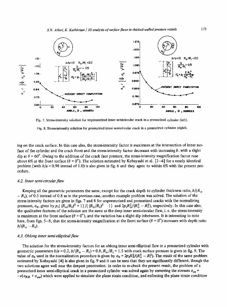
The solution for the stress-intensity factors for an oblong inner semi-elliptical flaw in a pressurized cylinder with geomertic parameters b/a = 0.2, b/(Ro - Ri) = 0.8, R o/R i = 1.5 with crack surface pressure is given in fig. 9. The value of Oo used in the normalization procedure is given by Oo = 2p~/(R2o - R ~ ) . The result of the same problem estimated by Kobayashi [4] is also given in fig. 9 and it can be seen that they are significantly different, though the two solutions agree well near the deepest penetration. In order to re-check the present result, the problem of a pressurized inner semi-elliptical crack in a pressurized cylinder was solved again by removing the stresses Ozz = --V(aRR + 0 ~ ) which were applied to simulate the plane strain condition, and enforcing the plane strain condition
174 S.N. Atluri, K. Kathiresan / 3D analysis o f surface flaws in thicked-walled pressure vessels
% 8
% +
U')
o
v
2.6- WITH CRACK PRESSURE - - - 2R? ~o=Pi R-~'~'RI = ( ~,}rl~,~.._/
' ~ - - - - - - - pLANE STRAIN / ~ ~ ) 2.~-,\ CON=rlON =~SEO \ ~ /
• , \ THROUGH DI~:q.ACEME_NT8 \ \ (WITH CRACK PRESSUI~E)
\ \ - t .\ ' ~ b/o = o.z -LI~ I
,~ Ro/Ri = 15 ;__j__j 1.4 \ ~ b/Ro-R i = 0.8
1.0
0.6 o % %
ELLIPTICAL ANGLE ~ e
WITHOUT CRACKePRESSURE ~.E~ ~. I , . r (RO/Ri ) -+ I ] \ ~ /
i \ o 'L(%/~i )=-' J
I \ R o /R i 1.5 ~J-M
1 o % %
ELLIPTICAL ANGLE I O
Fig. 9. Stress-intensity solution for oblong inner semi-elliptical crack in a pressurized cylinder (left).
Fig. 10. Stress-intensity solution for oblong inner semi-elliptical crack in a pressurized cylinder (right).
through suppressing the displacements at corresponding faces. The result obtained for this case is also given in fig. 9 by dotted lines and is very close to the result obtained by enforcing the plane strain condition through the stres- ses Ozz = - v(ORR + o ~ ) . The estimated value of stress-intensity magnification factor at the free surface (0 = 0 °) is 2.26, which is about 1.7 times higher than that of Kobayashi's [4] estimation, and at the deepest penetration (0 --- 90 °) is 1.19 with a dip at 0 = 45 °. The solution for stress-intensity factors for the same problem with no crack sur- face pressure is given in fig. 10, wherein the value of a0 used in the normalization procedure is given by o0 = Pi [ ( R o / R i ) 2 + 1]/[(Ro/Ri) 2 - 1 ]. The results are lower at all 0-locations as compared with the same problem with crack surface pressure and no comparative solution is given by Kobayashi [4].
~ 2 ,0
% 8 % + lID
1.8 b/a=l.O R o /Ri =1.5
2 Ri ~'
' , ~ ~7 7
1.4| \ I [ ~ L
"'1 , I.O l
o % % AN()LE , 0
~ 2.0-
18 bla "I,0
• ~, R o / R I = I . 5 \ "J - . , / /
" ~ O" O" I:> i RO~,_IR , , 6 \ b i I I ,,,
1'21 - \ Kolxlyallhi [4]
1.01 o % % ANGLE ~ e
Fig. 11. Stress-intensity solution for outer semicircular crack in a pressurized cylinder (left). Fig. 12. Stress-intensity solution for outer semicircular cracks in a pressurized cylinder (right).

S.N. AtluH, K. Kathiresan / 3D analysis o f surface flaws in thicked.walled pressure vessels 175
4.4. Outer semi-circular flaw
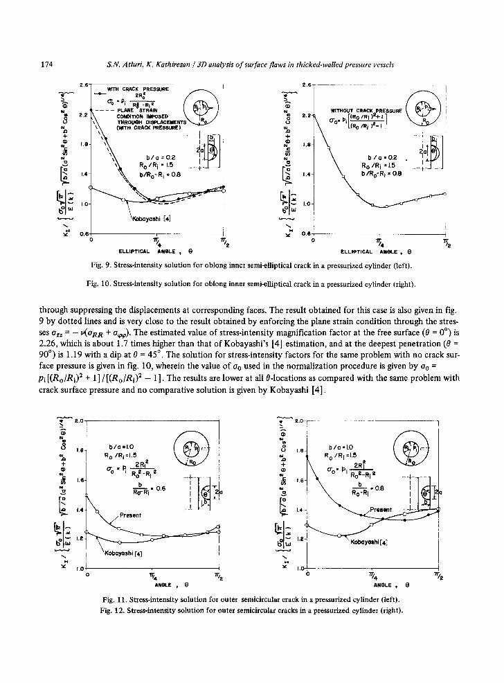
The results of the variation of stress-intensity factors for unpressurized outer semi-circular crack with geometric parameters (b/a = 1, Ro/R i = 1.5) and two depth to thickness ratios 0.6 and 0.8 are given in figs. 11 and 12, respec- tively. The value of oo used in the normalization procedure is also given by o0 = 2R?pi/(R2o - R~). The qualitative features of these two problems are also similar to the inner as well as outer semi-elliptical crack problems discussed. With all the geometric parameters kept constant, except the ratio of crack depth to the thickness of the thick- walled cylinder, one can observe the effect of increased stress-intensity magnification factor at all 0-locations for a deeper crack from figs. 11 and 12. The comparative estimates of Kobayashi [4] are also shown in figs. 11 and 12 and again were found to differ significantly for these problems.
4.5. Outer semi-elliptical flaw
The results of the variation of Kx for an unpressurized outer semi-elliptical crack with geometric parameters, (b/a = 0.6; Ro/R i = 1.5; b/(Ro - Ri) = 0.4) is shown in fig. 13. The stress-intensity factor varaiation is normalized with respect to the closed form solution of an embedded elliptical flaw, the faces of which are acted on by a uni- form pressure, Oo, equal to the hoop stress at the outer face of the cylinder due to internal pressure, Pi, namely Oo = 2R?pi/(R2o -- R~) .
The results estimated by Kobayashi [4] for an identical problem and by Blackburn and Hellen [5] for slightly different geometry (Ro/Ri = 1.461, whereas in the present case Ro/R i = 1.5) are also given in fig. 13. Again, as in case of inner surface cracks, the computed stress-intensity magnification factor is maximum at the front surface (0 = 0 °) and the magnification factor decreases continuously with increasing elliptical angle 0. The actual stress- intensity factor at 0 = 0 ° is only about 1.5% lower than the stress-intensity factor at 0 = 90 °. As can be seen from fig. 13, the present directly computed result agrees reasonably well with Blackburn's solution throughout except for first ten degrees of the elliptical angle. However, Kobayashi's solutions seems to differ significantly from the other two solutions. The 13% difference in stress-intensity magnification factor between present and Blackburn's solutions at the free surface (0 = 0 °) could be attributed to the indirect solution procedure, i. e. through the virtual
~4 g 0 % • I" 1.5
N .S oO
1.4.-
~ . = 1.3
" . 1.2"
I , I 0
• PRESENT
BLACKBURN [5]
KOBAYASHI [4 ]
b / a ': 0.6 R 0 / R i : 1.5
\ I~ 0.4 \ R°-Ri e I I I
f
ELLIPTICAL AIM(lIE t 0
Fig. 13. Stress-intensity solution for outer semi-elliptical cracks in a pressurized cylinder.

176 S.N. Atluri, K. Kathiresan / 3D analysis o f surface flaws in thicked-walled pressure vessels
crack extension method, and slight difference in the geometry of the problem in [5]. Thus, it appears that the method of estimation of stress-intensity factor in [4], through the solution for surface flaws in the flat plates modi- fied by curvature correction factor, is questionable.
5. Conclusions
The solution by the present procedure are found to be in reasonable agreement with those obtained through conventional finite element method, such as those of Blackburn and Hellen [5]. The procedure used by Kobayashi et al. [4], namely the alternating method for flat plates with "curvature corrections" to account for cylinderical geometry, gave excellent correlation with the solutions obtained by the present hybrid-displacement model in the case of pressurized and unpressurized semi-circular inner surface flaws in a pressurized cylinder [ 18]. But in the case of oblong semi-elliptical flaws and cracks penetrating deeper into the thickness, the alternating method used by Kobayashi [4] fails to yield results comparable to the present method. The procedure in [4] may not be valid for cases of crack depth in which the effects of back surface had to be considered. Again, in the alternating solution procedure of [4] the hoop stress variation along the thickness direction of the thick-walled cylinder was approxi- mated by polynomials, and since the solution of embedded elliptical crack in an infinite solid (needed in the alter- nating method) is available for only a limited class of polynomial crack pressure distributions, the above polyno- mial fitting of actual stresses may not be accurate enough. Moreover, in the case of oblong and deeper semi-elliptical surface cracks, a simple two-dimensional analog employing various curvature correction factors may not be an adequate modeling of a complex three-dimensional problem and may be questionable.
Acknowledgements
This work was supported in parts by AFOSR Grant 74-2667, NSF Grant 74-21346, and by supplemental funds from the Georgia Institute of Technology. The writers gratefully acknowledge this support.
References
[1] R.J. Clifton, E.R. Simonson, A.F. Jones and S.J. Green, SESA Paper no. 2407A (May 1975) to be published in Exp. Mech. [2] A.S. Kobayashi, N. Polvanich, A.F. Emery and W.J. Love, in: Computational Fracture Mechanics, E.F. Rybicki and S.E.
Benzley, eds. (ASME, New York, 1975) p. 121. [3] A.S. Kobayashi, A.F. Emery, N. Polvanich and W.J. Love, 3rd SMiRT Conf., London (1975) Paper G4/3. [4] A.S. Kobayashi, A.F. Emery, N. Polvanich and W.J. Love, Joint Conf. on Pressure Vessels and Pipings and Petroleum Mechan-
ical Engineering, Mexico City (1976); published in ASME Trans. [5] W.S. Blackburn and T.K. HeUen, Central Electricity Generating Board Report RD/B/N-3103 (July 1974). [6] D.J. Ayres, in: Computational Fracture Mechanics, E.F. Rybicki and S.E. Benzley, eds. (ASME, New York, 1975) p. 133. [7] T.K. Hellen and W.S. Blackburn, in: Computational Fracture Mechanics, E.F. Rybicki and S.E. Benzley, eds. (ASME, New
York, 1975)p. 103. [8] O.L. Bowie and C.E. Freese, Eng. Fracture Mech. 4 (2) (1972) 315. [9] J.H. Underwood, in: Stress Analysis and Growth of Crack, ASTM/STP 513 (1972) p. 59.
[10] M.K. Kassir and G.C. Sih, J. Appl. Mech. 33 (1966) 601. [ 11] G.C. Sih, Mechanics of Analysis and Solution of Crack Problems, vol. 1 (Noordhoff, Leydon, 1973) p. xxi. [12] S.N. Atluri, A.S, Kobayashi and M. Nakagaki, Int. J. Fracture 2 (2) (1975) 257. [13] S.N. Atluri, A.S. Kobayashi and M. Nakagaki, AIAA J. 13 (6) (1975) 734. [ 14] K. Kathiresan, PhD Dissertation, Georgia Institute of Technology (1976). [15] Pin Tong, Int. J. Numer. Methods Eng. 2 (1970) 73. [16] S.N. Atluri, K. Kathiresan and A.S. Kobayashi, Trans. 3rd SMiRT Conf., CECA/CEE/CEEA, Luxembourg, Sept. (1975)
Palaer L7/3. [17] S.N. Atluri and K. Kathiresan, AIAA/ASME 19th Structures, Structural Dynamics Conf., Bethesda, Maryland, 3-5 April 1978. [ 18] S.N. Atluri, K. Kathiresan, A.S. Kobayashi and M. Nakagaki, Proc. 3rd Int. Conf. on Pressure Vessel Technology, Part II,
(Tokyo, Japan, 1977) p. 527. [19] S.N. Atluri and K. Kathiresan, Trans. 4th SMiRT Conf., San Francisco (1977) Paper G5/4.