Embed Size (px)
Citation preview

NSB Solar Battery RangeDesigned for off grid applications
Visit our websiteTOÛNDOUTMOREwww.northstarbattery.com
NorthStar’s Solar Battery range uses advanced
OPZV tubular plate gel technology.
High capacity density and cyclic PERFORMANCE
Designed to DIN 40742
IEC 61427 solar tested
Maintenance-free and leakage-free construction
Not subject to road transport regulations (ADR)
if the conditions of special rule 598 (chapter 3.3)
are observed
Recyclable
Low self discharge
/PERATINGTEMPERATURE #TO#
YEARÜOATLIFEAT#&
/PTIONALHALOGEN FREE6/MATERIAL
/PTIONALHORIZONTALCONÛGURATION
Electrical Data and Dimensions
Type C1h
Ah
C10h
Ah
C20h
Ah
C72h
Ah
C100h
Ah
C120h
Ah
C240h
Ah
Ri 1)/®
Ik 2) kA
Length mm
Width mm
Height mm
Weight kg
Ue (100%)/Vpc 1.65 1.80 1.80 1.80 1.80 1.80 1.80
Ue (80%)/Vpc 1.74 1.91 1.91 1.91 1.91 1.91 1.91
NSB 4PVV 280 138 239 264 316 330 336 350 1.200 1.70 105 208 420 20.0
NSB 5PVV 350 167 287 316 378 394 400 417 0.960 2.15 126 208 420 23.0
NSB 6PVV 420 208 359 396 473 494 504 525 0.800 2.57 147 208 420 28.8
NSB 5PVV 550 256 444 498 573 588 594 612 0.710 2.88 126 208 535 32.0
NSB 6PVV 660 307 533 596 688 705 712 734 0.600 3.46 147 208 535 36.7
NSB 7PVV 770 346 598 668 770 786 794 816 0.510 4.04 168 208 535 41.0
NSB 6PVV 900 395 701 794 914 932 942 981 0.450 4.58 147 208 710 52.0
NSB 8PVV 1200 511 903 1,022 1,173 1,190 1,212 1,257 0.340 6.10 215 193 710 68.9
NSB 10PVV 1500 654 1,160 1,314 1,512 1,540 1,560 1,620 0.270 7.63 215 235 710 84.6
NSB 12PVV 1800 770 1,360 1,542 1,764 1,800 1,824 1,896 0.230 9.15 215 277 710 99.6
NSB 12PVV 2280 963 1,650 1,854 2,160 2,210 2,232 2,296 0.240 8.58 215 277 855 115.0
NSB 16PVV 3040 1,302 2,250 2,520 2,952 3,010 3,048 3,144 0.180 11.40 215 400 815 156.2
NSB 20PVV 3800 1,632 2,820 3,180 3,708 3,790 3,828 3,936 0.144 14.30 215 490 815 195.0
NSB 22PVV 4180 1,765 3,020 3,400 3,960 4,040 4,080 4,200 0.131 15.67 215 580 815 216.0
NSB 24PVV 4560 1,976 3,440 3,860 4,521 4,620 4,668 4,824 0.120 17.10 215 580 815 236.0
NSB 26PVV 4940 2,086 3,570 4,020 4,680 4,780 4,824 4,968 0.111 18.52 215 580 815 250.0
NSB Solar Battery Range
NorthStar in Europe, Middle East, Africa SiteTel Sweden ABStaffans Väg 6-8Box 7039, SE-192 07 Sollentuna, Stockholm, [email protected] Tel: +46 8 410 102 00Fax: +46 8 638 06 00
NorthStar in Asia-Pacific SiteTel Shanghai Co LtdBuilding 9, 1201 Gui Qiao RoadJin Qiao Export Process Zone, 201206 Shanghai, [email protected]: +86 21 5899 7610Fax: +86 21 3872 2201
NorthStar in the Americas NorthStar Battery Company LLC4000 Continental WaySpringfield, MO, 65803, United States of [email protected]: +1 417 575 8200Fax: +1 417 575 8250
!LL.3"3OLAR"ATTERIESMEETTESTSTANDARDS)%# AND)%#ANDSAFETYSTANDARDSFORventilation EN 50272-2.
www.northstarbattery.com
4ECHNICAL3PECIÛCATIONS
Terminal Positions
NSB 4PVV 280 - NSB 6 PVV 900
NSB 8PVV 1200 - NSB 12PVV 2280
NSB 16PVV 3040 NSB 20PVV 3800 - NSB 26PVV 4940
NSB SOLAR PVV SERIES
OPERATING INSTRUCTIONS
WARNINGS
Observe operating instructions and position them within sight of the battery! Work only on batteries under instruction of skilled personnel!
When working on batteries wear safety glasses and protective clothing! Comply with accident prevention rules as well as with EN 50272-2!
No smoking! Do not expose the battery to an open flame, a glowing fire or sparks as explosion and fire hazards exist.
Acid splashes in the eyes or on the skin must be washed out or off with plenty of water. Then see a doctor immediately. Clothing exposed to acid should be washed out with water without delay.
Explosion and fire hazard due to explosive gases escaping from the battery. Caution! Metal parts of the battery are always live, therefore do not place items or tools on the battery! Avoid short circuits!
The electrolyte (diluted sulphuric acid) is highly corrosive. Under normal operating conditions contact with electrolyte is prevented. In case of damage of the container contact with the gelled sulphuric acid has to be avoided. It is highly corrosive as well.
Cells are heavy! Ensure secure installation! Only use suitable transport equipment!
Dangerous voltage!
Usage of the battery which does not comply with the OPERATING INSTRUCTIONS, repairs carried out with spare parts not approved by the supplier, use of additives in the electrolyte or unauthorised interference with the battery will invalidate any claim for warranty.
Used batteries with this symbol are reusable goods and must be returned to the recycling process or must be disposed in accordance with the rules of the country concerned.
General Valve regulated lead-acid batteries must not be topped up with water through their entire life. The valves must not be opened, because access of oxygen discharges the cells. During charging the cells will release hydrogen through the valve. Observe the ventilation instruction EN 50272-2. Protect batteries from direct sunlight. For the assembly and operation of stationary battery installations EN 50272-2 applies. The battery must be installed and operated in such a way that the ambient temperature differences between the cells of one battery are < 3 K. 1. Requirements and preparations for installation 1.1 Before installation ensure that the battery room is clean and dry and is furnished with a lockable door. The battery room must be set out and marked according to DIN VDE 0510, Part 2. Particular attention must be paid to the following: - floor load-carrying capacity and nature (conveying paths and battery room) - electrolyte resistance of battery installation surface - no ignitable sources (e.g. open flame, lowing objects, electric switches) near the cell openings (500 mm thread measure) - ventilation conditions To ensure smooth operation, coordination between other persons working in the same room is necessary. 1.2. Check deliveries for completeness and damage. If necessary, clean all parts before assembling. 1.3. Observe all documentation included with the delivery (e. g. battery-, rack-, cabinet-assembly drawings). 1.4. Before renewing old batteries ensure that all electric leads are switched of (separator, fuses, switches). This must be carried out by qualified personnel. CAUTION: Do not carry out unauthorised switching! 1.5. Open-circuit voltage measurements of individual cells or block batteries. Ensure correct polarity. With unfilled, dry charged batteries these measurements can only be carried out after putting into operation. Fully charged PVV cells have an open-circuit voltages of 2.08-2.12 V/per cell at an electrolyte temperature of 20 °C. 2. Racks 2.1. Align the racks according to the installation drawing. Should an installation drawing be missing, the following minimum distances must be observed: From the wall: 100 mm on all sides for the cell or block container, or 50 mm for the rack. 1.5 meters with a nominal or component voltage > 120 V between non-insulated terminals or connectors and grounded parts (e. g. water pipes) or between the battery’s end terminals. During installation it must be ensured that DIN VDE 0510, Part 2 is adhered to (e.g. cover
NSB SOLAR PVV SERIES
electrically conductive parts with insulating mats). From ignitable sources: 500 mm (thread measure) from the nearest cell vent. From passageways: 1.5 x cell width (installation depth) but not less than 500 mm. 2.2. Align racks horizontally using the levelling parts or adjustable insulators provided. The distances of the support profiles must correspond with the cell size. Check rack stability and ensure all screw and clamp connectors are firmly seated. If stipulated, ground the rack or parts thereof. Protect screw connectors from corrosion. 2.3. Place each cell onto the rack with the correct polarity. Don’t lift the cells on the poles. With large cells it is recommended that cell installation should commence from the middle of the rack: Arrange cells or batteries plumb and level, with the correct polarity. If necessary clean the contact surface of the terminals and connectors. If necessary, fit insulating caps onto cell/block connectors and end terminals. Ensure short-circuit proof installation work. Wiring with a dielectric strength of at least 3 kV must be used, or a distance of approx. 10 mm between wiring and electrically conductive parts must be kept or the connectors must be furnished with additional insulation. Avoid mechanical stress on the cell/battery terminals. If applicable, remove transport plugs and replace with operation plugs. Measure the total voltage which should equal the total off-load voltages of the individual cells. If necessary, number through visibly the cells or block batteries (from the battery’s positive terminal to the negative terminal). Affix polarity labels for the battery connectors. After assembly completion affix nameplate integrated in operating instructions. Affix safety marking sign and operating instructions visibly. 3. Cabinets Only filled and charged cells or block batteries (vented or sealed) are built into cabinets. Assemble cabinet, place in designated location and align (observing UVV). Place cells or block batteries into the cabinet according to assembly plan and spacing specified, connect them and mark (see item 2.3). 4. Installing the battery Install the racks or cabinets provided for the installation in the correct location. Inspect all cells for mechanical damage. Cells may be operating in upright or – if ordered and designated correspondingly – in horizontal position. Having battery strings connected in parallel, care must be taken that the same thermal environment and the same electric connection resistance are applied. Therefore normally not more than 4 partial batteries are connected in parallel. Set up the cells with the correct polarity. The distance between cells should be 10 mm. If necessary the surfaces of the poles and connectors have to be cleaned. Multipole cells have to be connected using all poles with same diameter and length of connectors. The connectors have to be firmly seated by tightening the terminal screws with a torque of 22 ± 1 Nm. Cable connectors have to be secured during mounting by cable holders. 5. CE-marking From 01.01.97 an EC declaration of conformity under the low voltage regulation is required for batteries above 75 V nominal voltage with the corresponding CE labelling on the battery. The battery installer of the battery plant is responsible for issuing the declaration and affixing the CE label on or next to the battery’s nameplate. CAUTION: Before connecting to the charger ensure that all assembly work has been duly completed! 6. Commissioning Connect the battery to the DC power supply, with the charger switched off, battery fuses removed and the load disconnected, ensuring that the polarity is correct: Positive terminal of the battery to the positive terminal of the charger. If the cells have been stored for more than 4 weeks, check the open-circuit voltage (OCV) before start of charging to ascertain the optimum commissioning charge: • Charging according to 7.3c, if the cells have OCV’s > 2.08 V.
If the cells have OCV’s < 2.08 V charging according to 7.3b or 7.3d. In case of 7.3d charge one day per month storage time to equalise the state of charge of the cells.
• If cells have an OCV < 0.02 V below average, contact the battery manufacturer.
The first charge should be monitored to ensure that limits are not exceeded and that no unacceptable temperatures occur. When charging is finished switch off the charger or switch over to float charging as per 7.3c. 7. Operation 7.1 Operation modes: stand-by and buffer In this case the load, the DC power supply and the battery are connected permanently in parallel. Thereby the charging voltage is the operational voltage of the battery and also the system voltage. a) During stand-by operation (float) the DC power supply is
always able to provide the maximum load current and the battery charging current. The battery only supplies current, if the DC power supply fails. The charging voltage at 20 °C (68 °F) must be set to (2.25 V ± 1 %) x number of PVV cells.
b) During buffer operation the DC power supply is not always able to provide the maximum load current. The load current temporarily exceeds the rated current of the DC power supply. During this time the battery supplies current. Depending on the load and after having consulted the battery manufacturer, the charging voltage should be set at (2.25 - 2.30 V) x number of PVV cells.
7.2 General terms for discharging a) Discharge A battery is discharged when it supplies an electrical current by switching of the charger and connecting the load with the battery poles. During discharge, the active materials are converted to lead sulphate and water. Batteries have to be recharged immediately after a partial or complete discharge but at least within a period of one week up to 4 weeks to 100 %. b) Self discharge If the battery voltage is permanently less than float voltage (see 7.3.c) - e.g. without charge or voltage too small - the battery discharges by itself. It results in a loss of capacity and possible sulphation of the electrodes. c) Voltage drop When discharged with currents higher then I100, a fully charged battery shows a voltage drop in the beginning (about 5 %) of the discharge, followed by a voltage maximum at about 10 % of discharge time. The presence and the depth of this drop can be a fine indicator for the state of charge (SOC) before discharging. d) Discharge regimes Discharge capacities, currents and voltages are specified in the last page. For other discharge data (times, currents, capacities, end voltages, temperatures), please contact the supplier. Never discharge the battery below the specified final voltages. The end cell voltage for all discharges of 10 hours or longer is 1.8 V/cell. No more than specified capacities are to be discharged. Charge immediately after discharge as well as after partial discharge. 7.3 General terms for charging Charging must only be carried out with direct current. Chargers with IU- or IUI-characteristics according to DIN 41773 may be used. a) IU (or IUU) characteristics Starting with a given initially constant charging current (“I”) the cell or battery voltage reaches the given final value which depends on the charging requirement by the application. The charger automatically switches then to constant operating voltage (“U”, 7.1a). As long as the final voltage is not reached yet, the charging current is limited only by the charger. Typical values for constant currents are 0.5 to 2.0 times I10. Typical constant voltages are 2.25, 2.27, 2.35, 2.40 V/cell. The different voltages are given by the application. Please see exact values
NSB SOLAR PVV SERIES
in section "7.4 special cases". The IUU characteristic provides a switching point after a higher first constant voltage to operating voltage. b) IUI characteristics Very effective method in order to recharge batteries in a short time and to crack sulphations. At first, an IU characteristic is applied to the battery. After a given time held out at constant voltage, the charging method is then extended by using a reduced constant current (“I”). This current is limited to 1.5 A/100 Ah C10. The cell or battery voltage reaches values between 2.60 and 2.75 V/cell. Check if loads have to be disconnected before. If temperatures higher than 45 °C (113 °F) occur, the charging has to be interrupted. The fully charged state is reached, when the cell voltages have not risen for a period of 2 h. c) Float charge (float voltage) A battery is float charged, when the electrodes are sufficiently polarized in that quantity that the floating current compensates the self discharge rate (see 7.2b) of the battery. A fully charged battery remains at 100 % SOC while being floated. The float voltage depends on acid density. Please take the values from following table:
Floating voltage Battery type 2.25 V/cell ± 1 % PVV
d) Equalizing or boost charge Charging method with increased gassing activity at higher cell voltages (>2.33 V/cell), done with either increased constant voltage (e.g. 2.33 to 2.40 V/cell) or constant current. The application of this method shall be time (max. 72 h) and temperature limited to max. 45 °C (113 °F). When using constant currents, they are to be limited to 1.5 A/100 Ah C10. On exceeding the temperature maximum, the charging must either be stopped or proceeded with reduced current or be switched to float charge to allow the temperature to drop. The equalizing charge, when executed with constant current, is completed, when the individual cell voltages no longer increase within 2 hours. e) Ripple currents During recharging up to 2.40 V/cell the RMS value of the AC ripple current may reach temporarily max. 20 A/100 Ah C10. After recharging and at stand-by (float) or buffer operation the RMS value of the ripple current must not exceed 5 A/100 Ah C10. f) Charging with alternative power supply When using an alternative power supply, the battery charger is not always able to supply the maximum load current. The load current can exceed the nominal current of the battery charger. The battery supplies power during this period and the battery will not be fully charged. The charge voltage has, therefore, to be set at floating voltage up to 2.35 V/cell ±1 % x number of cells.
At regular discharges of less than 0.4 x C10 a charging voltage of 2.30 to 2.35 V/cell has to be used. At regular discharges from 0.4 to 0.6 x C10 the charging voltage should be 2.35 to 2.40 V/cell.
In accordance with item 7.3.d the charging time at those increased voltages shall be limited to maximum 72 h. If no discharge follows then switch to stand-by operation.
At stand-by operation without cycling the batteries should be operated at float charge with 2.25 V/cell ± 1 %. After deep discharge or after inadequate recharging an equalizing charging as per Item 7.3d is necessary. 7.4 Special cases a) Charging a new battery Can be done by using IU- or IUI-characteristics (7.3a and 7.3b) with increased voltage of 2.33 to 2.40 V/cell. Charging times:
IU IUI Min. 1 day Approx. 8 to 12 hours
b) Recharging After a discharge the battery can be recharged at operating voltage (see 7.1a). This can take weeks until months for a complete recharge.
To reduce the charging time the recharging can be carried out by using IUU-characteristics (7.3a) with increased voltage (2.33 to 2.40 V/cell) x number of cells with automatic reduction (switching point) to the operating voltage under 7.1a. Recharging times are dependant on the charging current available; as a rule they run to 12 to 24 hours at initial currents between 2xI10 to 0.5xI10. Using IUI-characteristics is also recommended. c) Equalizing charge After deep discharge or after inadequate recharging equalizing charging is necessary. See 7.3d. 7.5 Battery temperature and related charging voltage All technical data refer to the nominal temperature of 20 °C (68 °F). The recommended temperature range is 10 °C (50 °F) to 30 °C (86 °F). Higher temperatures reduce the operational life. Lower temperatures reduce the available capacity. Exceeding the temperature limit of 45 °C (113 °F) up to 55 °C (131 °F) is acceptable only for short periods. A temperature-related adjustment of the charging voltage within monthly averaged battery temperature of 10 °C (50 °F) to 45 °C (113 °F) must not be made. A decrease of the charging voltage at temperatures above 20 °C (68 °F) endangers the fully charged state of the battery. Below 10 °C (50 °F) in the monthly average the charging voltage should be increased (-0.003 V/cell/K) for a faster recharging. 8. Maintenance To avoid leakage currents and the associated risk of fire keep the battery dry and clean. Cleaning with clean water, no detergents, no solvents. Avoid electrostatic charges. During whole life time, the battery needs not to be refilled with water. The electrolyte is diluted sulphuric acid and fixed as GEL made with micro porous SiO2. To be measured and listed every 6 months: • battery voltage • voltages of some cells (pilot cells) • surface temperatures of pilot cells and the room temperature Every 12 months: • Voltages of all cells and surface temperatures of pilot cells
have to be measured and listed. • Connectors, racks and ventilation have to be visually checked
and restored if necessary. Should the float charge voltage of single cells deviate more than +0.2 V or -0.1 V from the average value (see 7.3c) and should the surface temperatures of different cells deviate more than 3 K, the customer service should be called. A service contract with the supplier or its local agent is recommended.
9. Tests Tests must be conducted according to IEC 60896-21. 10. Storage and taking out of operation Should batteries be stored or taken out of operation for extended periods, they must be stored fully charged in a dry frost-free room. To avoid damage one of the two charging methods has to be selected: a) Equalising charging every 3 months. If the room
temperatures are higher than 30 °C (86 °F), shorter intervals are necessary.
b) Float charging as under 7.3c. 11. Transport Cells/batteries are protected against short-circuit. They are no dangerous goods in accordance with the road and railway transportation regulations (ADR; RID) if they show no damage and are protected against sliding, falling over and damaging. They also have to be piled up on pallets in accordance with the ADR special rule 598 (Chap. 3.3). During sea and air transport of cells/batteries the rules of IMDG-Code or IATA-DGR must be followed.
NSB SOLAR PVV SERIES
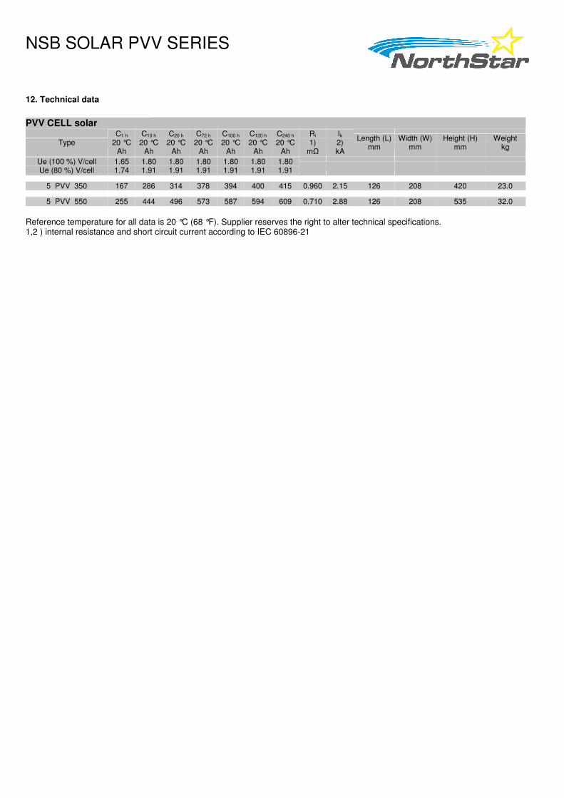
12. Technical data PVV CELL solar
Type C1 h
20 °C Ah
C10 h 20 °C
Ah
C20 h 20 °C
Ah
C72 h 20 °C
Ah
C100 h 20 °C
Ah
C120 h 20 °C
Ah
C240 h 20 °C
Ah
Ri 1)
mΩ
Ik 2) kA
Length (L) mm
Width (W) mm
Height (H) mm
Weight kg
Ue (100 %) V/cell Ue (80 %) V/cell
1.65 1.74
1.80 1.91
1.80 1.91
1.80 1.91
1.80 1.91
1.80 1.91
1.80 1.91
5 PVV 350 167 286 314 378 394 400 415 0.960 2.15 126 208 420 23.0
5 PVV 550 255 444 496 573 587 594 609 0.710 2.88 126 208 535 32.0
Reference temperature for all data is 20 °C (68 °F). Supplier reserves the right to alter technical specifications. 1,2 ) internal resistance and short circuit current according to IEC 60896-21

NSB SOLAR PVV SERIES
Contact Information
Northstar Battery Company LLC Northstar SiteTel AB
4000 Continental Way Staffans Väg 6-8
Springfield, MO 65803 Box 7039
USA SE-192 07 Sollentuna
Tel: +1 (417) 575-8200 Sweden
Fax: +1 (417) 575-8250 Tel: +46 8 410 102 00
Email: [email protected] Fax: +46 8 638 06 00
http://www.northstarbattery.com Email: [email protected]
MATERIAL SAFETY DATA SHEET
SOLAR PVV LEAD ACID BATTERY
Springfield, Missouri
Date: 03-02-10 DCR: 1644-S10 ISO Clause: 4.3.1 DCN: MSD-430-02 Page: 1 of 7
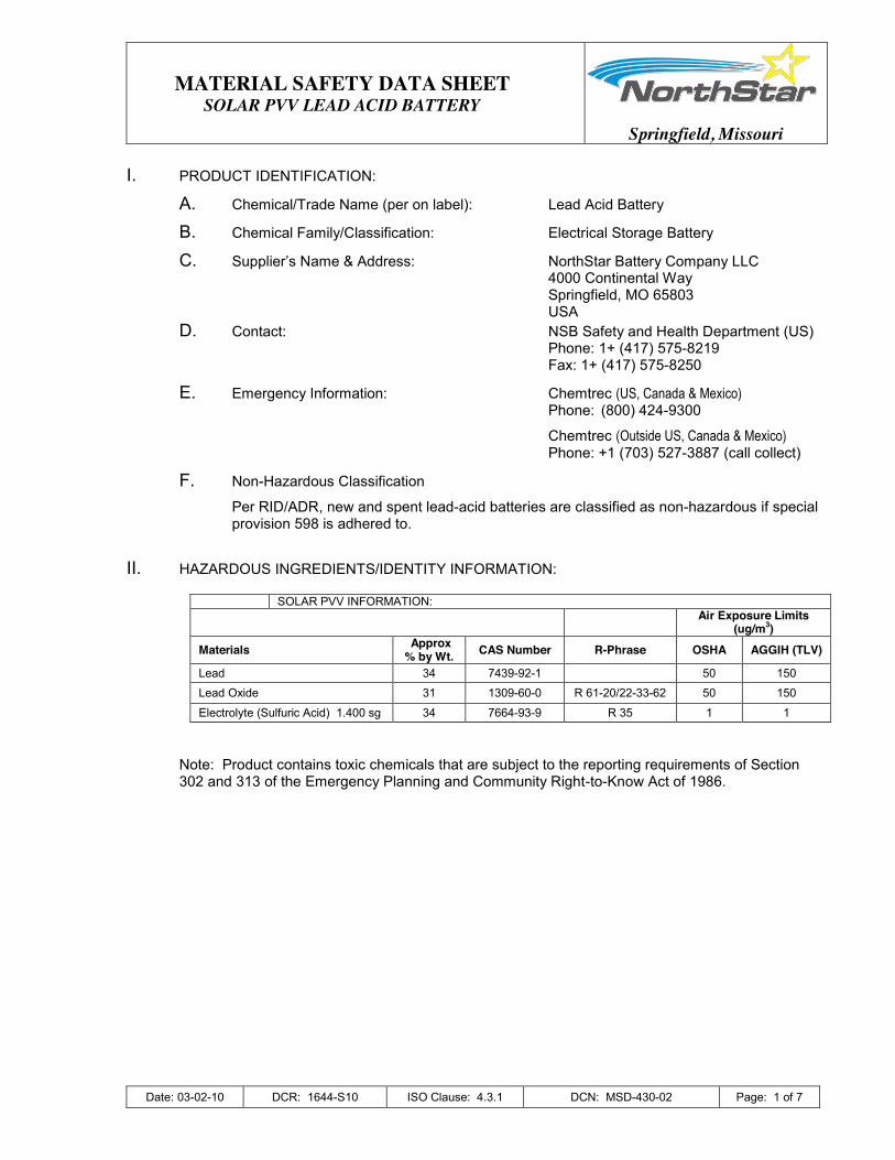
I. PRODUCT IDENTIFICATION:
A. Chemical/Trade Name (per on label): Lead Acid Battery
B. Chemical Family/Classification: Electrical Storage Battery
C. Supplier’s Name & Address: NorthStar Battery Company LLC 4000 Continental Way Springfield, MO 65803 USA
D. Contact: NSB Safety and Health Department (US) Phone: 1+ (417) 575-8219 Fax: 1+ (417) 575-8250
E. Emergency Information: Chemtrec (US, Canada & Mexico) Phone: (800) 424-9300
Chemtrec (Outside US, Canada & Mexico) Phone: +1 (703) 527-3887 (call collect)
F. Non-Hazardous Classification
Per RID/ADR, new and spent lead-acid batteries are classified as non-hazardous if special provision 598 is adhered to.
II. HAZARDOUS INGREDIENTS/IDENTITY INFORMATION:
SOLAR PVV INFORMATION: Air Exposure Limits
(ug/m3) Materials Approx
% by Wt. CAS Number R-Phrase OSHA AGGIH (TLV)
Lead 34 7439-92-1 50 150
Lead Oxide 31 1309-60-0 R 61-20/22-33-62 50 150
Electrolyte (Sulfuric Acid) 1.400 sg 34 7664-93-9 R 35 1 1
Note: Product contains toxic chemicals that are subject to the reporting requirements of Section 302 and 313 of the Emergency Planning and Community Right-to-Know Act of 1986.

MATERIAL SAFETY DATA SHEET
SOLAR PVV LEAD ACID BATTERY
Springfield, Missouri
Date: 03-02-10 DCR: 1644-S10 ISO Clause: 4.3.1 DCN: MSD-430-02 Page: 2 of 7
PHYSICAL DATA: A. Electrolyte:
1. Form: Liquid 2. Specific Gravity: 1.2 – 1.3 3. Boiling Point: 108 – 114 C (226 – 237 F) 4. Freezing Point: -35 to -60 C 5. % Volatiles By Weight: Not Applicable 6. Solubility in Water: 100% 7. Melting Point Lead: 327 C (621 F) 8. Vapor Pressure (20 C) 14.6 mbar
B. Lead:
1. Form: Solid 2. Boiling Point: 1740 C 3. Freezing Point: 327 C 4. Solubility in Water: 150 ppm
C. Appearance and Odor
1. Electrolyte is a clear liquid with an acidic odor.
III. HEALTH HAZARD INFORMATION:
Under normal operating conditions the internal material will not be hazardous to your health. Only internally exposed material during production or case breakage or extreme heat (fire) may be hazardous to your health.
A. Routes of Entry:
1. Inhalation: Acid mist from formation process may cause respiratory irritation.
2. Skin Contact: Acid may cause irritation, burns and/or ulceration.
3. Skin Absorption Not a significant route of entry.
4. Eye Contact: Acid may cause severe irritation, burns, cornea damage and/or blindness.
5. Ingestion: Acid may cause irritation of mouth, throat, esophagus and stomach.
B. Signs and Symptoms of Over Exposure:
1. Acute Effects: Over exposure to lead may lead to loss of appetite, constipation, sleeplessness and fatigue. Over exposure to acid may lead to skin irritation, corneal damage of the eyes and upper respiratory system.
2. Chronic Effects: Lead and its components may cause damage to kidneys and nervous system. Acid and its components may cause lung damage and pulmonary conditions.
MATERIAL SAFETY DATA SHEET
SOLAR PVV LEAD ACID BATTERY
Springfield, Missouri
Date: 03-02-10 DCR: 1644-S10 ISO Clause: 4.3.1 DCN: MSD-430-02 Page: 3 of 7
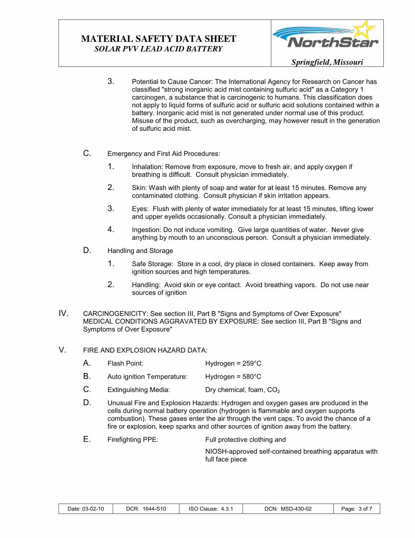
3. Potential to Cause Cancer: The International Agency for Research on Cancer has classified "strong inorganic acid mist containing sulfuric acid" as a Category 1 carcinogen, a substance that is carcinogenic to humans. This classification does not apply to liquid forms of sulfuric acid or sulfuric acid solutions contained within a battery. Inorganic acid mist is not generated under normal use of this product. Misuse of the product, such as overcharging, may however result in the generation of sulfuric acid mist.
C. Emergency and First Aid Procedures:
1. Inhalation: Remove from exposure, move to fresh air, and apply oxygen if breathing is difficult. Consult physician immediately.
2. Skin: Wash with plenty of soap and water for at least 15 minutes. Remove any contaminated clothing. Consult physician if skin irritation appears.
3. Eyes: Flush with plenty of water immediately for at least 15 minutes, lifting lower and upper eyelids occasionally. Consult a physician immediately.
4. Ingestion: Do not induce vomiting. Give large quantities of water. Never give anything by mouth to an unconscious person. Consult a physician immediately.
D. Handling and Storage
1. Safe Storage: Store in a cool, dry place in closed containers. Keep away from ignition sources and high temperatures.
2. Handling: Avoid skin or eye contact. Avoid breathing vapors. Do not use near sources of ignition
IV. CARCINOGENICITY: See section III, Part B "Signs and Symptoms of Over Exposure"
MEDICAL CONDITIONS AGGRAVATED BY EXPOSURE: See section III, Part B "Signs and Symptoms of Over Exposure"
V. FIRE AND EXPLOSION HAZARD DATA:
A. Flash Point: Hydrogen = 259°C
B. Auto ignition Temperature: Hydrogen = 580°C
C. Extinguishing Media: Dry chemical, foam, CO2
D. Unusual Fire and Explosion Hazards: Hydrogen and oxygen gases are produced in the cells during normal battery operation (hydrogen is flammable and oxygen supports combustion). These gases enter the air through the vent caps. To avoid the chance of a fire or explosion, keep sparks and other sources of ignition away from the battery.
E. Firefighting PPE: Full protective clothing and
NIOSH-approved self-contained breathing apparatus with full face piece

MATERIAL SAFETY DATA SHEET
SOLAR PVV LEAD ACID BATTERY
Springfield, Missouri
Date: 03-02-10 DCR: 1644-S10 ISO Clause: 4.3.1 DCN: MSD-430-02 Page: 4 of 7
REACTIVITY DATA: F. Stability: Stable
G. Conditions to Avoid: Sparks and other sources of ignition.
H. Incompatibility: (materials to avoid)
1. Lead/lead compounds: Potassium, carbides, sulfides, peroxides, phosphorus, sulfur.
2. Battery electrolyte (acid): Combustible materials, strong reducing agents, most metals, carbides, organic materials, chlorates, nitrates, picrates, and fulminates.
I. Hazardous Decomposition Products:
1. Lead/lead compounds: Oxides of lead and sulfur.
2. Battery electrolyte (acid): Hydrogen, sulfur dioxide, and sulfur trioxide.
J. Conditions to Avoid:
High temperature. Battery electrolyte (acid) will react with water to produce heat. Can react with oxidizing or reducing agents.
VI. CONTROL MEASURES:
A. Engineering Controls:
Store lead/acid batteries with adequate ventilation. Room ventilation is required for batteries utilized for standby power generation. Never recharge batteries in an unventilated, enclosed space.
B. Work Practices:
Do not remove vent covers. Follow shipping and handling instructions which are applicable to the battery type. To avoid damage to terminals and seals, do not double-stack industrial batteries.
C. Personal Protective Equipment:
1. Respiratory Protection: None required under normal handling conditions. During battery formation (high-rate charge condition), acid mist can be generated which may cause respiratory irritation. Also, if acid spillage occurs in a confined space, exposure may occur. If irritation occurs, wear a respirator suitable for protection against acid mist.
2. Eyes and Face: Chemical splash goggles are preferred. Also acceptable are "visor-gogs" or a chemical face shield worn over safety glasses.
3. Hands, Arms, Body: Vinyl coated, VC, gauntlet type gloves with rough finish are preferred.
4. Other Special Clothing and Equipment: Safety shoes are recommended when handling batteries. All footwear must meet requirements of ANSI Z41.1 -Rev. 1972.

MATERIAL SAFETY DATA SHEET
SOLAR PVV LEAD ACID BATTERY
Springfield, Missouri
Date: 03-02-10 DCR: 1644-S10 ISO Clause: 4.3.1 DCN: MSD-430-02 Page: 5 of 7
VII. ACCIDENTAL RELEASE MEASURES:
A. Not applicable under normal conditions.
B. In case of damage resulting in breakage of the battery container, see VI, Sec. C Personal Protective Equipment.
VIII. PRECAUTIONS FOR SAFE HANDLING AND USE:
A. Hygiene Practices: Following contact with internal battery components, wash hands thoroughly before eating, drinking, or smoking.
B. Respiratory Protection: Wear safety glasses. Do not permit flames or sparks in the vicinity of battery(s). If battery electrolyte (acid) comes in contact with clothing, discard clothing.
C. Protective Measures:
1. Remove combustible materials and all sources of ignition. Cover spills with soda ash (sodium carbonate) or quicklime (calcium oxide). Mix well. Make certain mixture is neutral, then collect residue and place in a drum or other suitable container. Dispose of as hazardous waste.
2. Wear acid-resistant boots, chemical face shield, chemical splash goggles, and acid-resistant gloves. Do not release un-neutralized acid.
D. Waste Disposal Method (*):
1. Battery electrolyte (acid): Neutralize as above for a spill, collect residue, and place in a drum or suitable container. Dispose of as hazardous waste.
2. Do not flush lead contaminated acid to sewer.
3. In case of accidental spill, utilize personal protective equipment, i.e., face shield, rubber apron, rubber safety shoes.
4. Batteries: Send to lead smelter for reclamation following applicable Federal, State and local regulations. Product can be recycled along with automotive (SLI) lead acid batteries.
5. Battery may be returned, shipping pre-paid, to NorthStar Battery or any distributor for recycling. See Section I, Part D for NSB contact information or visit our web site @ www.northstarbattery.com.
*In accordance to Local, State and Federal regulations and laws.
E. Other Handling and Storage Precautions: S-phrases
1. S – ½ Keep locked up and out of reach of children.
2. S – 26 In case of contact with eyes rinse immediately with plenty of water and seek medical advice.
3. S – 30 Never add water to this product (applies for concentrated acid only, and not for refilling the battery with water.)
4. S – 45 In case of accident or if you feel unwell seek medical advice immediately (show the label where possible.)
MATERIAL SAFETY DATA SHEET
SOLAR PVV LEAD ACID BATTERY
Springfield, Missouri
Date: 03-02-10 DCR: 1644-S10 ISO Clause: 4.3.1 DCN: MSD-430-02 Page: 6 of 7
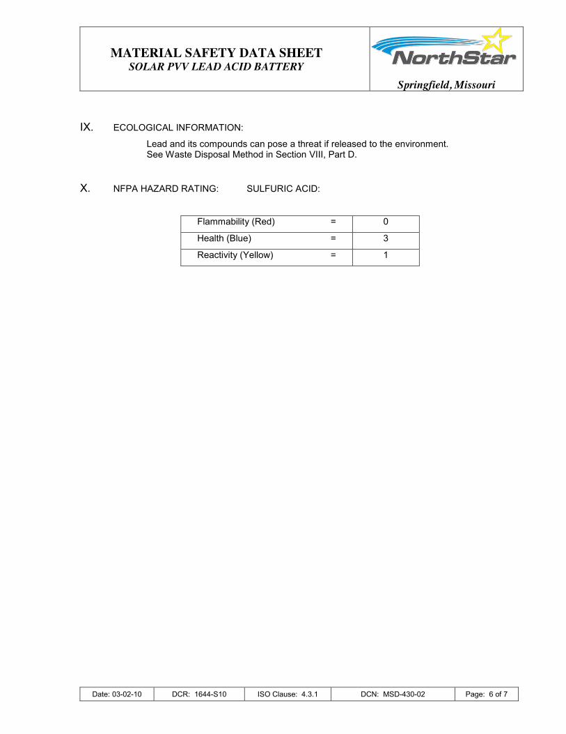
IX. ECOLOGICAL INFORMATION:
Lead and its compounds can pose a threat if released to the environment. See Waste Disposal Method in Section VIII, Part D.
X. NFPA HAZARD RATING: SULFURIC ACID:
Flammability (Red) = 0
Health (Blue) = 3
Reactivity (Yellow) = 1

MATERIAL SAFETY DATA SHEET
SOLAR PVV LEAD ACID BATTERY
Springfield, Missouri
Date: 03-02-10 DCR: 1644-S10 ISO Clause: 4.3.1 DCN: MSD-430-02 Page: 7 of 7
Technical Data (Reference temperature 20°C)
Type C1 h Ah
C10 h Ah
C20 h Ah
C72 h Ah
C100 h Ah
C120 h Ah
C240 h Ah
Ri * mΩ
Isc * kA
Length mm (in)
Width mm (in)
Height mm (in)
Weight kg (lbs)
Ue (100%) / Vpc Ue (80%) / Vpc
1.65 1.74
1.80 1.91
1.80 1.91
1.80 1.91
1.80 1.91
1.80 1.91
1.80 1.91
4 PVV 280 138 239 264 316 330 336 350 1.200 1.70 105 (4.13) 208 (8.19) 420 (16.54) 20.0 (44.1) 5 PVV 350 167 287 316 378 394 400 417 0.960 2.15 126 (4.96) 208 (8.19) 420 (16.54) 23.0 (50.7) 6 PVV 420 208 359 396 473 494 504 525 0.800 2.57 147 (5.79) 208 (8.19) 420 (16.54) 28.8 (63.5)
5 PVV 550 256 444 498 573 588 594 612 0.710 2.88 126 (4.96) 208 (8.19) 535 (21.06) 32.0 (70.5) 6 PVV 660 307 533 596 688 705 712 734 0.600 3.46 147 (5.79) 208 (8.19) 535 (21.06) 36.7 (80.9) 7 PVV 770 346 598 668 770 786 794 816 0.510 4.04 168 (6.61) 208 (8.19) 535 (21.06) 41.0 (90.4)
6 PVV 900 395 701 794 914 932 942 981 0.450 4.58 147 (5.79) 208 (8.19) 710 (27.95) 52.0 (114.6)
8 PVV 1200 511 903 1,022 1,173 1,190 1,212 1,257 0.340 6.10 215 (8.46) 193 (7.60) 710 (27.95) 68.9 (151.9) 10 PVV 1500 654 1,160 1,314 1,512 1,540 1,560 1,620 0.270 7.63 215 (8.46) 235 (9.25) 710 (27.95) 84.6 (186.5) 12 PVV 1800 770 1,360 1,542 1,764 1,800 1,824 1,896 0.230 9.15 215 (8.46) 277 (10.91) 710 (27.95) 99.6 (219.6)
12 PVV 2280 963 1,650 1,854 2,160 2,210 2,232 2,296 0.240 8.58 215 (8.46) 277 (10.91) 855 (33.66) 115.0 (253.5) 16 PVV 3040 1,302 2,250 2,520 2,952 3,010 3,048 3,144 0.180 11.40 215 (8.46) 400 (15.75) 815 (32.09) 156.2 (344.4) 20 PVV 3800 1,632 2,820 3,180 3,708 3,790 3,828 3,936 0.144 14.30 215 (8.46) 490 (19.29) 815 (32.09) 195.0 (429.9) 22 PVV 4180 1,765 3,020 3,400 3,960 4,040 4,080 4,200 0.131 15.67 215 (8.46) 580 (22.83) 815 (32.09) 216.0 (476.2) 24 PVV 4560 1,976 3,440 3,860 4,521 4,620 4,668 4,824 0.120 17.10 215 (8.46) 580 (22.83) 815 (32.09) 236.0 (520.3) 26 PVV 4940 2,086 3,570 4,020 4,680 4,780 4,824 4,968 0.111 18.52 215 (8.46) 580 (22.83) 815 (32.09) 250.0 (551.2)
*: Ri : Internal Resistance and Isc : Short Circuit Current values according to IEC 60896-21.


![Manual Nsb[1]](https://img.dokumen.tips/doc/110x75/55cf9a19550346d033a076e2/manual-nsb1.jpg)

![[Nsb] kisa 세미나자료 2016_11_17](https://img.dokumen.tips/doc/110x75/58ee4ee31a28abb7698b465f/nsb-kisa-20161117.jpg)