Embed Size (px)
Citation preview
Potential dangers from accidents during installation and use are divided into the following three categories. Closely observe these warnings, they are critical to your safety.
Prohibited DisconnectPower Ground Be sure to do
WARNING: If the information in this manual is not followed exactly, a fire or explosion may result causing property damage, personal injury or death.
NORITZ AMERICA CORPORATION Installation Manual
CONDENSING TANKLESS GAS WATER HEATERNRC663-FSV (EZTR40)
(Indoor Installation)
DANGER indicates an imminently hazardous situation which, if not avoided, will result in death or serious injury.
WARNING indicates a potentially hazardous situation which, if not avoided, could result in death or serious injury.
CAUTION indicates a potentially hazardous situation which, if not avoided, may result in minor or moderate injury.
DANGERWARNINGCAUTION
SBB809LRev. 08/14
Requests to Installers• In order to use the water heater safely, read this installation manual carefully, and follow the
installation instructions.• Failures and damage caused by erroneous work or work not as instructed in this manual are not
covered by the warranty.• Check that the installation was done properly in accordance with this Installation Manual upon completion.• After completing installation, please either place this Installation Manual in a plastic pouch and
attach it to the side of the water heater (or the inside of the pipe cover or recess box if applicable), or hand it to the customer to retain for future reference. Also, be sure to fill in all of the required items on the warranty and to hand the warranty to the customer along with the Owner's Guide.
CAUTION
FOR USE IN RESIDENTIAL APPLICATIONS.Installation must conform with local codes, or in the absence of local codes, the National Fuel Gas Code, ANSI Z223.1/NFPA 54- latest edition.Noritz America reserves the right to discontinue, or change at any time, the designs and/or specifications of its products without notice.
Low NOx Approved by
SCAQMD14 ng/J or 20 ppm(Natural Gas Only)
2
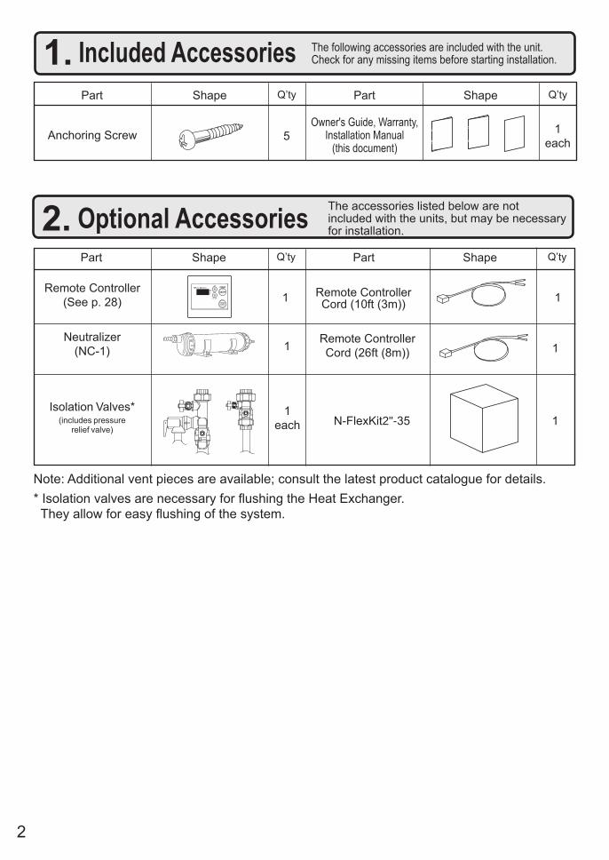
1. Included Accessories The following accessories are included with the unit.Check for any missing items before starting installation.
Q’tyShapePart
Anchoring Screw 1each
Part Shape Q’ty
5
1Remote Controller
(See p. 28)Remote Controller Cord (10ft (3m))1
2. Optional Accessories The accessories listed below are not included with the units, but may be necessary for installation.
Q’tyShapePartPart Shape Q’ty
Remote Controller Cord (26ft (8m)) 1
1each
Isolation Valves*(includes pressure
relief valve)
Owner's Guide, Warranty,Installation Manual
(this document)
1N-FlexKit2"-35
Note: Additional vent pieces are available; consult the latest product catalogue for details.
1Neutralizer
(NC-1)
* Isolation valves are necessary for flushing the Heat Exchanger. They allow for easy flushing of the system.
3
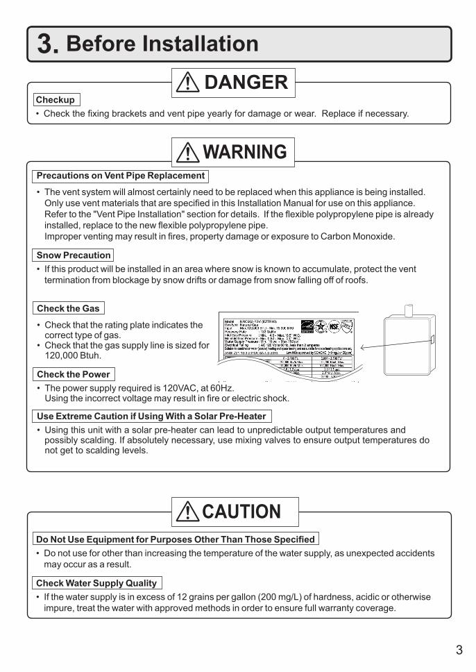
Check the Gas
• Check that the rating plate indicates the correct type of gas.• Check that the gas supply line is sized for 120,000 Btuh.
Check the Power• The power supply required is 120VAC, at 60Hz. Using the incorrect voltage may result in fire or electric shock.
Use Extreme Caution if Using With a Solar Pre-Heater• Using this unit with a solar pre-heater can lead to unpredictable output temperatures and possibly scalding. If absolutely necessary, use mixing valves to ensure output temperatures do
not get to scalding levels.
3. Before Installation
Checkup• Check the fixing brackets and vent pipe yearly for damage or wear. Replace if necessary.
DANGER
Do Not Use Equipment for Purposes Other Than Those Specified• Do not use for other than increasing the temperature of the water supply, as unexpected accidents
may occur as a result.
Check Water Supply Quality• If the water supply is in excess of 12 grains per gallon (200 mg/L) of hardness, acidic or otherwise
impure, treat the water with approved methods in order to ensure full warranty coverage.
WARNING
CAUTION
Precautions on Vent Pipe Replacement
• The vent system will almost certainly need to be replaced when this appliance is being installed. Only use vent materials that are specified in this Installation Manual for use on this appliance.
Refer to the "Vent Pipe Installation" section for details. If the flexible polypropylene pipe is already installed, replace to the new flexible polypropylene pipe. Improper venting may result in fires, property damage or exposure to Carbon Monoxide.
Snow Precaution• If this product will be installed in an area where snow is known to accumulate, protect the vent
termination from blockage by snow drifts or damage from snow falling off of roofs.
4
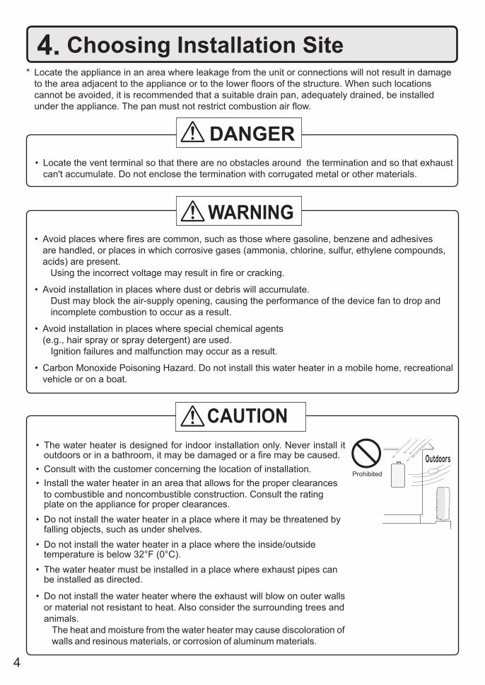
4. Choosing Installation Site* Locate the appliance in an area where leakage from the unit or connections will not result in damage
to the area adjacent to the appliance or to the lower floors of the structure. When such locations cannot be avoided, it is recommended that a suitable drain pan, adequately drained, be installed under the appliance. The pan must not restrict combustion air flow.
• Locate the vent terminal so that there are no obstacles around the termination and so that exhaust can't accumulate. Do not enclose the termination with corrugated metal or other materials.
• Avoid places where fires are common, such as those where gasoline, benzene and adhesives are handled, or places in which corrosive gases (ammonia, chlorine, sulfur, ethylene compounds, acids) are present.
Using the incorrect voltage may result in fire or cracking.
• Avoid installation in places where dust or debris will accumulate.Dust may block the air-supply opening, causing the performance of the device fan to drop and incomplete combustion to occur as a result.
• Avoid installation in places where special chemical agents (e.g., hair spray or spray detergent) are used.
Ignition failures and malfunction may occur as a result.
• Carbon Monoxide Poisoning Hazard. Do not install this water heater in a mobile home, recreational vehicle or on a boat.
• The water heater is designed for indoor installation only. Never install it outdoors or in a bathroom, it may be damaged or a fire may be caused.
• Consult with the customer concerning the location of installation.• Install the water heater in an area that allows for the proper clearances
to combustible and noncombustible construction. Consult the rating plate on the appliance for proper clearances.
• Do not install the water heater in a place where it may be threatened by falling objects, such as under shelves.
• Do not install the water heater in a place where the inside/outside temperature is below 32°F (0°C).
• The water heater must be installed in a place where exhaust pipes can be installed as directed.
• Do not install the water heater where the exhaust will blow on outer walls or material not resistant to heat. Also consider the surrounding trees and animals.
The heat and moisture from the water heater may cause discoloration of walls and resinous materials, or corrosion of aluminum materials.
DANGER
WARNING
CAUTION
Prohibited
5
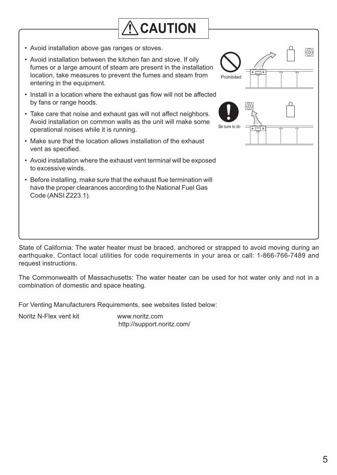
• Avoid installation above gas ranges or stoves.
• Avoid installation between the kitchen fan and stove. If oily fumes or a large amount of steam are present in the installation location, take measures to prevent the fumes and steam from entering in the equipment.
• Install in a location where the exhaust gas flow will not be affected by fans or range hoods.
• Take care that noise and exhaust gas will not affect neighbors. Avoid installation on common walls as the unit will make some operational noises while it is running.
• Make sure that the location allows installation of the exhaust vent as specified.
• Avoid installation where the exhaust vent terminal will be exposed to excessive winds.
• Before installing, make sure that the exhaust flue termination will have the proper clearances according to the National Fuel Gas Code (ANSI Z223.1).
State of California: The water heater must be braced, anchored or strapped to avoid moving during an earthquake. Contact local utilities for code requirements in your area or call: 1-866-766-7489 and request instructions.
Be sure to do
Prohibited
CAUTION
The Commonwealth of Massachusetts: The water heater can be used for hot water only and not in a combination of domestic and space heating.
For Venting Manufacturers Requirements, see websites listed below:
Noritz N-Flex vent kit www.noritz.com http://support.noritz.com/
6
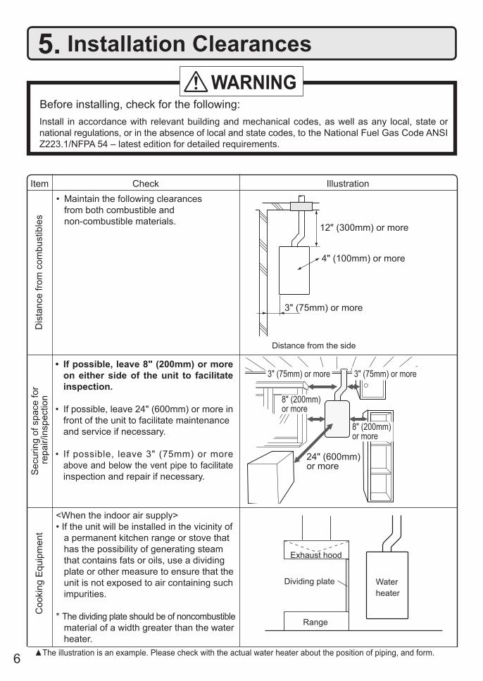
5. Installation Clearances
Before installing, check for the following:Install in accordance with relevant building and mechanical codes, as well as any local, state or national regulations, or in the absence of local and state codes, to the National Fuel Gas Code ANSI Z223.1/NFPA 54 – latest edition for detailed requirements.
WARNING
Item
Dis
tanc
e fro
m c
ombu
stib
les
• Maintain the following clearances from both combustible and non-combustible materials.
Check Illustration
• If possible, leave 8" (200mm) or more on either side of the unit to facilitate inspection.
• If possible, leave 24" (600mm) or more in front of the unit to facilitate maintenance and service if necessary.
• If possible, leave 3" (75mm) or more above and below the vent pipe to facilitate inspection and repair if necessary.S
ecur
ing
of s
pace
for
repa
ir/in
spec
tion
24" (600mm) or more
Distance from the side
12" (300mm) or more
3" (75mm) or more
4" (100mm) or more
3" (75mm) or more
8" (200mm) or more
8" (200mm) or more
<When the indoor air supply>• If the unit will be installed in the vicinity of
a permanent kitchen range or stove that has the possibility of generating steam that contains fats or oils, use a dividing plate or other measure to ensure that the unit is not exposed to air containing such impurities.
* The dividing plate should be of noncombustible material of a width greater than the water heater.
Exhaust hood
Range
Dividing plate Waterheater
Coo
king
Equ
ipm
ent
▲The illustration is an example. Please check with the actual water heater about the position of piping, and form.
3" (75mm) or more
7
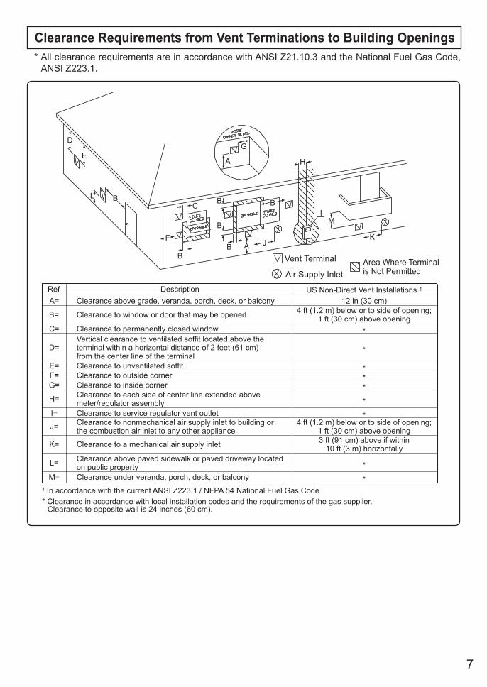
DescriptionRefA= Clearance above grade, veranda, porch, deck, or balcony
B= Clearance to window or door that may be opened
C= Clearance to permanently closed window
D=Vertical clearance to ventilated soffit located above theterminal within a horizontal distance of 2 feet (61 cm) from the center line of the terminal
E= Clearance to unventilated soffitF= Clearance to outside cornerG= Clearance to inside corner
H= Clearance to each side of center line extended abovemeter/regulator assembly
I= Clearance to service regulator vent outlet
J= Clearance to nonmechanical air supply inlet to building orthe combustion air inlet to any other appliance
K= Clearance to a mechanical air supply inlet
L= Clearance above paved sidewalk or paved driveway locatedon public propertyClearance under veranda, porch, deck, or balconyM=
1 In accordance with the current ANSI Z223.1 / NFPA 54 National Fuel Gas Code* Clearance in accordance with local installation codes and the requirements of the gas supplier.
Clearance to opposite wall is 24 inches (60 cm).
*
***
*
*
*
*
3 ft (91 cm) above if within10 ft (3 m) horizontally
*
12 in (30 cm)4 ft (1.2 m) below or to side of opening;
1 ft (30 cm) above opening
4 ft (1.2 m) below or to side of opening;1 ft (30 cm) above opening
US Non-Direct Vent Installations 1
Vent Terminal
D
E
B
B
F
B
A
G
H
IC B
M
KJ
B
B
L
Air Supply InletArea Where Terminalis Not Permitted
A
Clearance Requirements from Vent Terminations to Building Openings* All clearance requirements are in accordance with ANSI Z21.10.3 and the National Fuel Gas Code,
ANSI Z223.1.
8
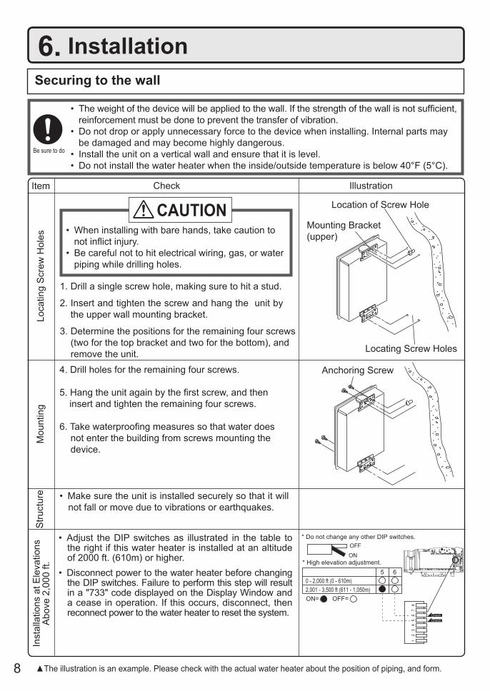
6. Installation Securing to the wall
IllustrationCheck
4. Drill holes for the remaining four screws.
5. Hang the unit again by the first screw, and then insert and tighten the remaining four screws.
6. Take waterproofing measures so that water does not enter the building from screws mounting the device.
• Make sure the unit is installed securely so that it will not fall or move due to vibrations or earthquakes.
1. Drill a single screw hole, making sure to hit a stud.
2. Insert and tighten the screw and hang the unit by the upper wall mounting bracket.
3. Determine the positions for the remaining four screws (two for the top bracket and two for the bottom), and remove the unit.
• The weight of the device will be applied to the wall. If the strength of the wall is not sufficient, reinforcement must be done to prevent the transfer of vibration.
• Do not drop or apply unnecessary force to the device when installing. Internal parts may be damaged and may become highly dangerous.
• Install the unit on a vertical wall and ensure that it is level.• Do not install the water heater when the inside/outside temperature is below 40°F (5°C).
Loca
ting
Scr
ew H
oles
Mou
ntin
gS
truct
ure
• When installing with bare hands, take caution to not inflict injury.
• Be careful not to hit electrical wiring, gas, or water piping while drilling holes.
Item
CAUTION
Be sure to do
Mounting Bracket(upper)
Location of Screw Hole
Locating Screw Holes
Inst
alla
tions
at E
leva
tions
A
bove
2,0
00 ft
.
• Adjust the DIP switches as illustrated in the table to the right if this water heater is installed at an altitude of 2000 ft. (610m) or higher.
• Disconnect power to the water heater before changing the DIP switches. Failure to perform this step will result in a "733" code displayed on the Display Window and a cease in operation. If this occurs, disconnect, then reconnect power to the water heater to reset the system.
Anchoring Screw
▲The illustration is an example. Please check with the actual water heater about the position of piping, and form.
* Do not change any other DIP switches.
* High elevation adjustment.65
2,001 - 3,500 ft (611 - 1,050m)0 - 2,000 ft (0 - 610m)
ON= OFF=
9
Filling the condensate trap with water
DANGERWhen initial start up, make sure that you perform the following procedures. This is to prevent dangerous exhaust gases from entering the building. Failure to following procedure could result in severe personal injury or death.
After installing the drain pipe, make sure that the area around the unit is well ventilated; open a window or a door if necessary. Then, operate the unit and verify that condensate is coming out of the drain pipe. (During normal use of the unit, condensate will begin to discharge from the drain pipe within 15 minutes of use. However, depending on the season and/or installation site conditions, it may take longer.)
10
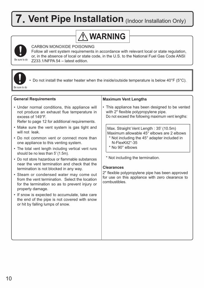
Maximum Vent Lengths
• This appliance has been designed to be vented with 2" flexible polypropylene pipe.
Do not exceed the following maximum vent lengths:
Max. Straight Vent Length : 35' (10.5m) Maximum allowable 45° elbows are 2 elbows* Not including the 45° adapter included in
N-FlexKit2"-35* No 90° elbows
* Not including the termination.
7. Vent Pipe Installation (Indoor Installation Only)
WARNING
Be sure to do
CARBON MONOXIDE POISONINGFollow all vent system requirements in accordance with relevant local or state regulation, or, in the absence of local or state code, in the U.S. to the National Fuel Gas Code ANSI Z233.1/NFPA 54 – latest edition.
• Under normal conditions, this appliance will not produce an exhaust flue temperature in excess of 149°F.
Refer to page 12 for additional requirements.• Make sure the vent system is gas tight and
will not leak.• Do not common vent or connect more than
one appliance to this venting system.• The total vent length including vertical vent runs
should be no less than 5' (1.5m).• Do not store hazardous or flammable substances
near the vent termination and check that the termination is not blocked in any way.
• Steam or condensed water may come out from the vent termination. Select the location for the termination so as to prevent injury or property damage.
• If snow is expected to accumulate, take care the end of the pipe is not covered with snow or hit by falling lumps of snow.
General Requirements
Clearances2" flexible polypropylene pipe has been approved for use on this appliance with zero clearance to combustibles.
• Do not install the water heater when the inside/outside temperature is below 40°F (5°C).
Be sure to do
11
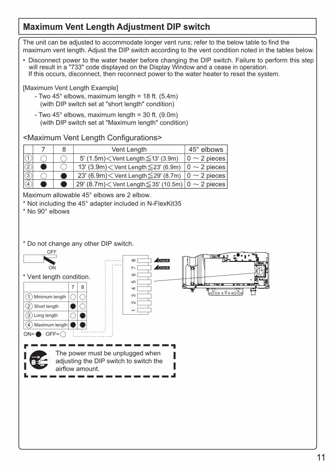
Minimum length
Short length
* Do not change any other DIP switch.
* Not including the 45° adapter included in N-FlexKit35
* No 90° elbows
Maximum allowable 45° elbows are 2 elbow.
* Vent length condition.
7
ON= OFF=
1
2
Long length
Maximum length
3
4
1
2
3
4
8
7 8 Vent Length 45° elbows
5' (1.5m) Vent Length 13' (3.9m) 0 2 pieces
13' (3.9m) Vent Length 23' (6.9m) 0 2 pieces
23' (6.9m) Vent Length 29' (8.7m) 0 2 pieces
29' (8.7m) Vent Length 35' (10.5m) 0 2 pieces
The power must be unplugged when adjusting the DIP switch to switch the airflow amount.
The unit can be adjusted to accommodate longer vent runs; refer to the below table to find the maximum vent length. Adjust the DIP switch according to the vent condition noted in the tables below.
Maximum Vent Length Adjustment DIP switch
- Two 45° elbows, maximum length = 18 ft. (5.4m) (with DIP switch set at "short length" condition)
- Two 45° elbows, maximum length = 30 ft. (9.0m) (with DIP switch set at "Maximum length" condition)
[Maximum Vent Length Example]
• Disconnect power to the water heater before changing the DIP switch. Failure to perform this step will result in a "733" code displayed on the Display Window and a cease in operation.
If this occurs, disconnect, then reconnect power to the water heater to reset the system.
<Maximum Vent Length Configurations>
12
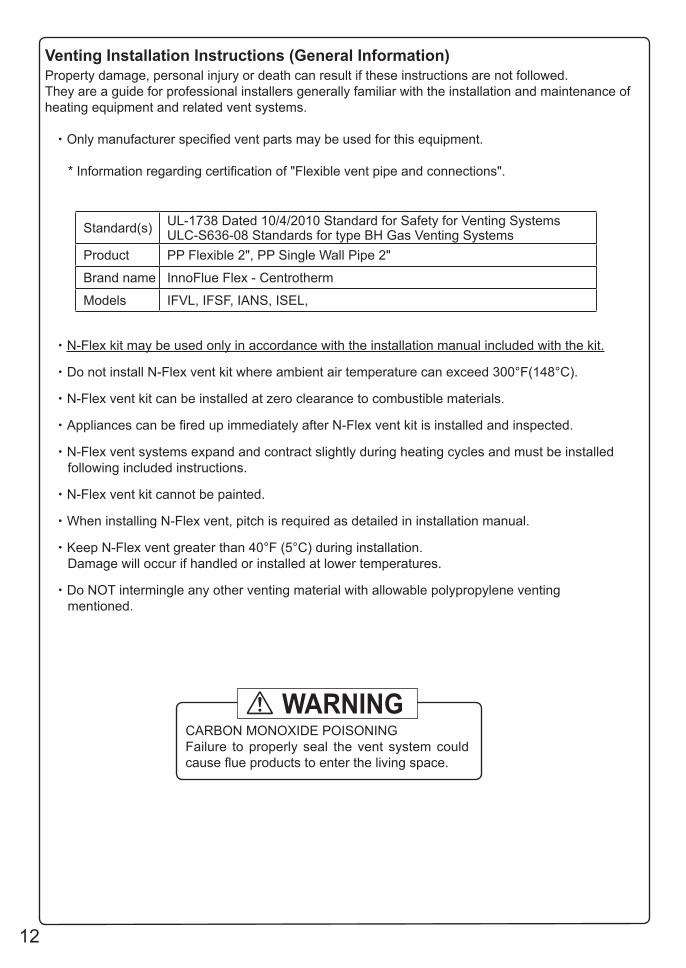
Venting Installation Instructions (General Information)Property damage, personal injury or death can result if these instructions are not followed. They are a guide for professional installers generally familiar with the installation and maintenance of heating equipment and related vent systems.
・Only manufacturer specified vent parts may be used for this equipment.
* Information regarding certification of "Flexible vent pipe and connections".
・N-Flex kit may be used only in accordance with the installation manual included with the kit.
・Do not install N-Flex vent kit where ambient air temperature can exceed 300°F(148°C).
・N-Flex vent kit can be installed at zero clearance to combustible materials.
・Appliances can be fired up immediately after N-Flex vent kit is installed and inspected.
・N-Flex vent systems expand and contract slightly during heating cycles and must be installed following included instructions.
・N-Flex vent kit cannot be painted.
・When installing N-Flex vent, pitch is required as detailed in installation manual.
・Keep N-Flex vent greater than 40°F (5°C) during installation. Damage will occur if handled or installed at lower temperatures.
・Do NOT intermingle any other venting material with allowable polypropylene venting mentioned.
Standard(s) UL-1738 Dated 10/4/2010 Standard for Safety for Venting SystemsULC-S636-08 Standards for type BH Gas Venting Systems
Product PP Flexible 2", PP Single Wall Pipe 2"
Brand name InnoFlue Flex - Centrotherm
Models IFVL, IFSF, IANS, ISEL,
CARBON MONOXIDE POISONINGFailure to properly seal the vent system could cause flue products to enter the living space.
WARNING
13
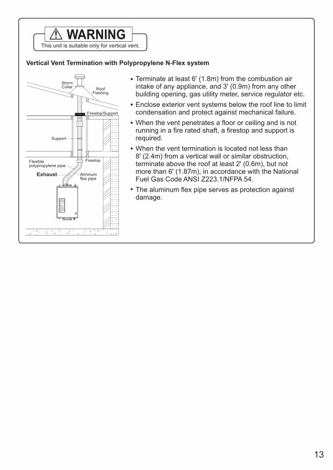
Vertical Vent Termination with Polypropylene N-Flex system
Firestop
Firestop/Support
RoofFlashing
StormCollar
Support
Alminum flex pipe
Flexiblepolypropylene pipe
•
•
•
•
•
Terminate at least 6' (1.8m) from the combustion airintake of any appliance, and 3' (0.9m) from any other building opening, gas utility meter, service regulator etc.
Enclose exterior vent systems below the roof line to limit condensation and protect against mechanical failure.
When the vent penetrates a floor or ceiling and is not running in a fire rated shaft, a firestop and support is required.
When the vent termination is located not less than 8' (2.4m) from a vertical wall or similar obstruction, terminate above the roof at least 2' (0.6m), but not more than 6' (1.87m), in accordance with the National Fuel Gas Code ANSI Z223.1/NFPA 54.
The aluminum flex pipe serves as protection against damage.
Exhaust
This unit is suitable only for vertical vent.WARNING
14
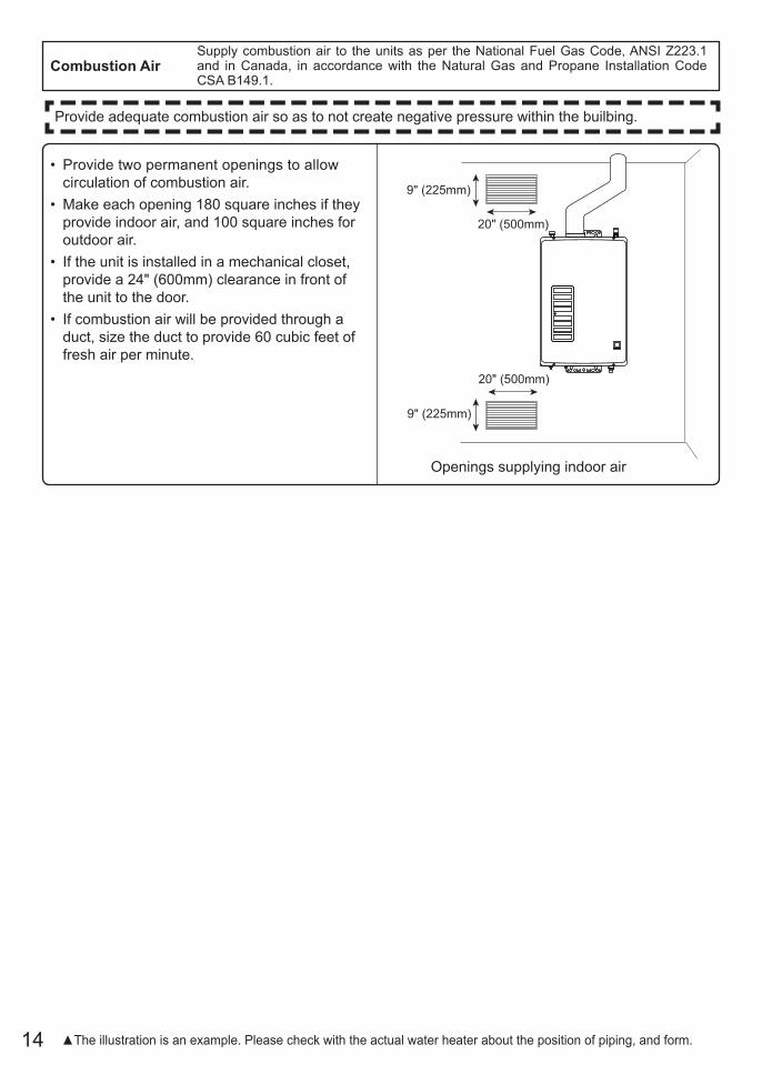
• Provide two permanent openings to allow circulation of combustion air.
• Make each opening 180 square inches if they provide indoor air, and 100 square inches for outdoor air.
• If the unit is installed in a mechanical closet, provide a 24" (600mm) clearance in front of the unit to the door.
• If combustion air will be provided through a duct, size the duct to provide 60 cubic feet of fresh air per minute.
Combustion Air
Openings supplying indoor air
9" (225mm)
20" (500mm)
9" (225mm)
20" (500mm)
▲The illustration is an example. Please check with the actual water heater about the position of piping, and form.
Supply combustion air to the units as per the National Fuel Gas Code, ANSI Z223.1 and in Canada, in accordance with the Natural Gas and Propane Installation Code CSA B149.1.
Provide adequate combustion air so as to not create negative pressure within the builbing.
15
Follow the instructions from the gas supplier.8. Gas Piping
Gas TypeThe gas type indicated on the water heater rating plate (NG or LP) must match the type of gas being supplied to the water heater.
Gas ConversionsIf the gas type supplied does not match the gas type on the rating plate, contact your water heater supplier for a replacement unit with the proper gas type. If a gas type conversion must be made, there are conversion kits available for some models. [The conversion kit shall be installed by a qualified service agency in accordance with the manufacturer’s instructions and all applicable codes and requirements of the authority having jurisdiction. The qualified service agency is responsible for the proper installation of this kit. Improper installation of this kit will void the warranty. Conversion kits will only be shipped directly to the Distributor or Agency performing the conversion.]
MeterThe gas meter must be sized properly for the water heater and other gas appliances to operate properly. Select a gas meter capable of supplying the entire btuh demand of all gas appliances in the building.
The guidelines and examples we have provided in this manual section are for reference only.The sizing and installation of the gas system for this water heater, as with any gas appliance, is the sole responsibility of the installer. The installer must be professionally trained to do such work and must always follow all local and national codes and regulations. Gas line sizing calculations must be performed for every installation. Please contact Noritz America at 866-766-7489 if you have any questions or concerns.
CAUTION
RegulatorsEnsure that all gas regulators used are operating properly and providing gas pressures within the specified range of the water heater being installed. Excess gas inlet pressure may cause serious accidents.
CAUTION
PressureCheck the gas supply pressure immediately upstream at a location provided by the gas company. Supplied gas pressure must be within the limits shown in the specifications section with all gas appliances operating. The inlet gas pressure must be within the range specified. This is for the purposes of input adjustment. Low gas pressure may cause a loss of flame or ignition failure at other appliances in the home, which may result in unburned gas in the home. Serious accidents such as fire or explosion may result.
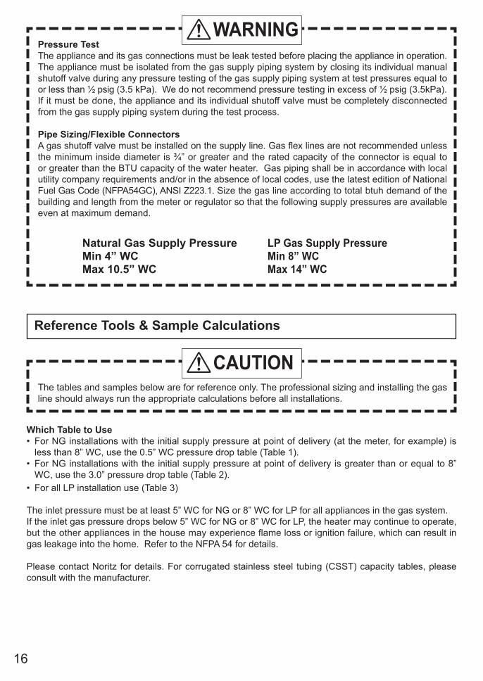
Measuring Gas PressureIn order to check the gas supply pressure to the unit, a tap is provided on the gas inlet. Remove the 9/32” hex head/Philips screw from the tap, and connect a manometer using a silicon tube. Open up at least 2 fixtures and hold in the maximum manifold pressure button on the circuit board. Please call Noritz for details.
WARNING
16
Pressure TestThe appliance and its gas connections must be leak tested before placing the appliance in operation. The appliance must be isolated from the gas supply piping system by closing its individual manual shutoff valve during any pressure testing of the gas supply piping system at test pressures equal to or less than ½ psig (3.5 kPa). We do not recommend pressure testing in excess of ½ psig (3.5kPa). If it must be done, the appliance and its individual shutoff valve must be completely disconnected from the gas supply piping system during the test process.
Pipe Sizing/Flexible Connectors A gas shutoff valve must be installed on the supply line. Gas flex lines are not recommended unless the minimum inside diameter is ¾” or greater and the rated capacity of the connector is equal to or greater than the BTU capacity of the water heater. Gas piping shall be in accordance with local utility company requirements and/or in the absence of local codes, use the latest edition of National Fuel Gas Code (NFPA54GC), ANSI Z223.1. Size the gas line according to total btuh demand of the building and length from the meter or regulator so that the following supply pressures are available even at maximum demand.
WARNING
Natural Gas Supply PressureMin 4” WCMax 10.5” WC
LP Gas Supply PressureMin 8” WCMax 14” WC
Reference Tools & Sample Calculations
The tables and samples below are for reference only. The professional sizing and installing the gas line should always run the appropriate calculations before all installations.
CAUTION
Which Table to Use• For NG installations with the initial supply pressure at point of delivery (at the meter, for example) is
less than 8” WC, use the 0.5” WC pressure drop table (Table 1). • For NG installations with the initial supply pressure at point of delivery is greater than or equal to 8”
WC, use the 3.0” pressure drop table (Table 2). • For all LP installation use (Table 3)
The inlet pressure must be at least 5” WC for NG or 8” WC for LP for all appliances in the gas system.If the inlet gas pressure drops below 5” WC for NG or 8” WC for LP, the heater may continue to operate, but the other appliances in the house may experience flame loss or ignition failure, which can result in gas leakage into the home. Refer to the NFPA 54 for details.
Please contact Noritz for details. For corrugated stainless steel tubing (CSST) capacity tables, please consult with the manufacturer.
17
Pipe Size
Length (including fittings)10' 20' 30' 40' 50' 60' 70' 80' 90' 100' 125'
(3m) (6m) (9m) (12m) (15m) (18m) (21m) (24m) (27m) (30m) (38m)3/4" 360 247 199 170 151 137 126 117 110 104 921" 678 466 374 320 284 257 237 220 207 195 173
1 1/4" 1,390 957 768 657 583 528 486 452 424 400 3551 1/2" 2,090 1,430 1,150 985 873 791 728 677 635 600 532
2" 4,020 2,760 2,220 1,900 1,680 1,520 1,400 1,300 1,220 1,160 1,0202 1/2" 6,400 4,400 4,400 3,020 2,680 2,430 2,230 2,080 1,950 1,840 1,630
3" 11,300 7,780 7,780 5,350 4,740 4,290 3,950 3,760 3,450 3,260 2,8904" 23,100 15,900 12,700 10,900 9,660 8,760 8,050 7,490 7,030 6,640 5,890
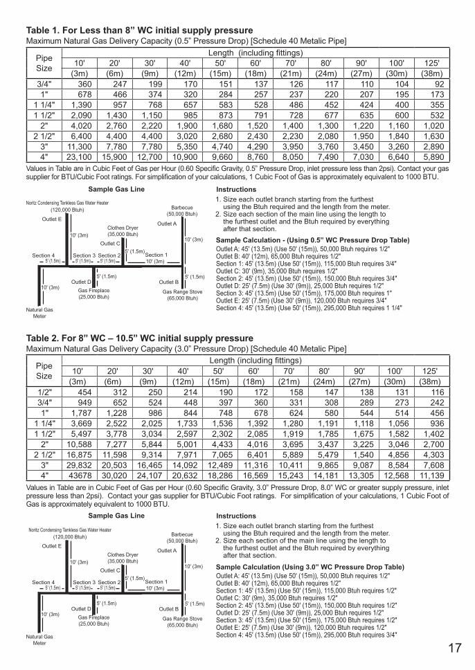
Table 1. For Less than 8” WC initial supply pressureMaximum Natural Gas Delivery Capacity (0.5” Pressure Drop) [Schedule 40 Metalic Pipe]
Values in Table are in Cubic Feet of Gas per Hour (0.60 Specific Gravity, 0.5” Pressure Drop, inlet pressure less than 2psi). Contact your gas supplier for BTU/Cubic Foot ratings. For simplification of your calculations, 1 Cubic Foot of Gas is approximately equivalent to 1000 BTU.
Instructions1. Size each outlet branch starting from the furthest using the Btuh required and the length from the meter.2. Size each section of the main line using the length to the furthest outlet and the Btuh required by everything after that section.
Sample Gas Line
Sample Calculation - (Using 0.5” WC Pressure Drop Table)Outlet A: 45' (13.5m) (Use 50' (15m)), 50,000 Btuh requires 1/2"Outlet B: 40' (12m), 65,000 Btuh requires 1/2"Section 1: 45' (13.5m) (Use 50' (15m)), 115,000 Btuh requires 3/4"Outlet C: 30' (9m), 35,000 Btuh requires 1/2"Section 2: 45' (13.5m) (Use 50' (15m)), 150,000 Btuh requires 3/4"Outlet D: 25' (7.5m) (Use 30' (9m)), 25,000 Btuh requires 1/2"Section 3: 45' (13.5m) (Use 50' (15m)), 175,000 Btuh requires 1"Outlet E: 25' (7.5m) (Use 30' (9m)), 120,000 Btuh requires 3/4"Section 4: 45' (13.5m) (Use 50' (15m)), 295,000 Btuh requires 1 1/4"Natural Gas
Meter
Noritz Condensing Tankless Gas Water Heater(120,000 Btuh)
Clothes Dryer(35,000 Btuh)
Barbecue(50,000 Btuh)
Gas Range Stove(65,000 Btuh)
10' (3m)10' (3m)
10' (3m)
10' (3m)
5' (1.5m)
5' (1.5m)5' (1.5m)
5' (1.5m)5' (1.5m) 5' (1.5m)
Gas Fireplace(25,000 Btuh)
Section 3 Section 2 Section 1
Outlet A
Outlet B
Outlet C
Outlet D
Outlet E
Section 4
Table 2. For 8” WC – 10.5” WC initial supply pressureMaximum Natural Gas Delivery Capacity (3.0” Pressure Drop) [Schedule 40 Metalic Pipe]
Values in Table are in Cubic Feet of Gas per Hour (0.60 Specific Gravity, 3.0” Pressure Drop, 8.0” WC or greater supply pressure, inlet pressure less than 2psi). Contact your gas supplier for BTU/Cubic Foot ratings. For simplification of your calculations, 1 Cubic Foot of Gas is approximately equivalent to 1000 BTU.
Natural GasMeter
Clothes Dryer(35,000 Btuh)
Barbecue(50,000 Btuh)
Gas Range Stove(65,000 Btuh)
10' (3m)10' (3m)
10' (3m)
10' (3m)
5' (1.5m)
5' (1.5m)5' (1.5m)
5' (1.5m)5' (1.5m) 5' (1.5m)
Gas Fireplace(25,000 Btuh)
Instructions1. Size each outlet branch starting from the furthest using the Btuh required and the length from the meter.2. Size each section of the main line using the length to the furthest outlet and the Btuh required by everything after that section.
Sample Gas Line
Sample Calculation (Using 3.0” WC Pressure Drop Table)Outlet A: 45' (13.5m) (Use 50' (15m)), 50,000 Btuh requires 1/2"Outlet B: 40' (12m), 65,000 Btuh requires 1/2"Section 1: 45' (13.5m) (Use 50' (15m)), 115,000 Btuh requires 1/2"Outlet C: 30' (9m), 35,000 Btuh requires 1/2"Section 2: 45' (13.5m) (Use 50' (15m)), 150,000 Btuh requires 1/2"Outlet D: 25' (7.5m) (Use 30' (9m)), 25,000 Btuh requires 1/2"Section 3: 45' (13.5m) (Use 50' (15m)), 175,000 Btuh requires 1/2"Outlet E: 25' (7.5m) (Use 30' (9m)), 120,000 Btuh requires 1/2" Section 4: 45' (13.5m) (Use 50' (15m)), 295,000 Btuh requires 3/4"
Section 3 Section 2 Section 1
Outlet A
Outlet B
Outlet C
Outlet D
Outlet E
Section 4
Noritz Condensing Tankless Gas Water Heater(120,000 Btuh)
Pipe Size
Length (including fittings)10' 20' 30' 40' 50' 60' 70' 80' 90' 100' 125'
(3m) (6m) (9m) (12m) (15m) (18m) (21m) (24m) (27m) (30m) (38m)1/2" 454 312 250 214 190 172 158 147 138 131 1163/4" 949 652 524 448 397 360 331 308 289 273 2421" 1,787 1,228 986 844 748 678 624 580 544 514 456
1 1/4" 3,669 2,522 2,025 1,733 1,536 1,392 1,280 1,191 1,118 1,056 9361 1/2" 5,497 3,778 3,034 2,597 2,302 2,085 1,919 1,785 1,675 1,582 1,402
2" 10,588 7,277 5,844 5,001 4,433 4,016 3,695 3,437 3,225 3,046 2,7002 1/2" 16,875 11,598 9,314 7,971 7,065 6,401 5,889 5,479 1,540 4,856 4,303
3" 29,832 20,503 16,465 14,092 12,489 11,316 10,411 9,865 9,087 8,584 7,6084" 43678 30,020 24,107 20,632 18,286 16,569 15,243 14,181 13,305 12,568 11,139
18
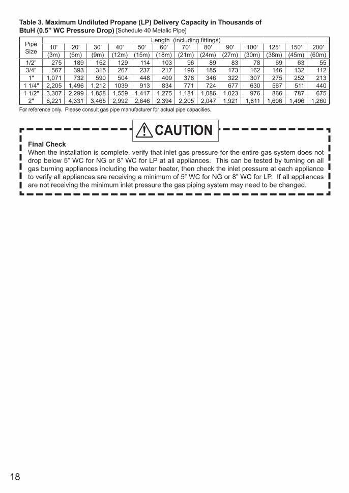
Table 3. Maximum Undiluted Propane (LP) Delivery Capacity in Thousands of BtuH (0.5” WC Pressure Drop) [Schedule 40 Metalic Pipe]
For reference only. Please consult gas pipe manufacturer for actual pipe capacities.
Final CheckWhen the installation is complete, verify that inlet gas pressure for the entire gas system does not drop below 5” WC for NG or 8” WC for LP at all appliances. This can be tested by turning on all gas burning appliances including the water heater, then check the inlet pressure at each appliance to verify all appliances are receiving a minimum of 5” WC for NG or 8” WC for LP. If all appliances are not receiving the minimum inlet pressure the gas piping system may need to be changed.
CAUTION
Pipe Size
Length (including fittings)10' 20' 30' 40' 50' 60' 70' 80' 90' 100' 125' 150' 200'
(3m) (6m) (9m) (12m) (15m) (18m) (21m) (24m) (27m) (30m) (38m) (45m) (60m)1/2" 275 189 152 129 114 103 96 89 83 78 69 63 553/4" 567 393 315 267 237 217 196 185 173 162 146 132 1121" 1,071 732 590 504 448 409 378 346 322 307 275 252 213
1 1/4" 2,205 1,496 1,212 1039 913 834 771 724 677 630 567 511 4401 1/2" 3,307 2,299 1,858 1,559 1,417 1,275 1,181 1,086 1,023 976 866 787 675
2" 6,221 4,331 3,465 2,992 2,646 2,394 2,205 2,047 1,921 1,811 1,606 1,496 1,260
19
Pipe Size
Length (including fittings)10' 20' 30' 40' 50' 60' 70' 80' 90' 100' 125' 150' 200'
(3m) (6m) (9m) (12m) (15m) (18m) (21m) (24m) (27m) (30m) (38m) (45m) (60m)1/2" 275 189 152 129 114 103 96 89 83 78 69 63 553/4" 567 393 315 267 237 217 196 185 173 162 146 132 1121" 1,071 732 590 504 448 409 378 346 322 307 275 252 213
1 1/4" 2,205 1,496 1,212 1039 913 834 771 724 677 630 567 511 4401 1/2" 3,307 2,299 1,858 1,559 1,417 1,275 1,181 1,086 1,023 976 866 787 675
2" 6,221 4,331 3,465 2,992 2,646 2,394 2,205 2,047 1,921 1,811 1,606 1,496 1,260
9. Water PipingThis appliance is suitable for combination potable water and space heating applications. It cannot be used for space heating applications only. Do not use this appliance if any part has been underwater. Immediately call a qualified service technician to inspect the appliance and replace any part of the control system and gas control which has been under water.
If the water heater is installed in a closed water supply system, such as one having a backflow preventer in the cold water supply line, means shall be provided to control thermal expansion. Contact the water supplier or a local plumbing inspector on how to control this situation.
A pressure relief valve must be installed near the hot water outlet that is rated in accordance with and complying with either The Standard for Relief Valves and Automatic Shutoff Devices for Hot Water Supply Systems, ANSI Z21.22, or The ANSI/ASME Boiler and Pressure Vessel Code, Section IV (Heating Boilers). This pressure relief valve must be capable of an hourly Btu rated temperature steam discharge of 120,000 Btuh. Multiple valves may be used. The pressure relief capacity must not exceed 150 psig. No valve shall be placed between the relief valve and the water heater. The relief valve must be installed such that the discharge will be conducted to a suitable place for disposal when relief occurs. No reducing coupling or other restriction may be installed in the discharge line. The discharge line must be installed to allow complete drainage of both the valve and the line. If this unit is installed with a separate storage vessel, the separate vessel must have its own temperature and pressure relief valve. This valve must also comply with The Standard for Relief Valves and Automatic Gas Shutoff Devices for Hot Water Supply Systems, ANSI Z21.22. (in the U.S. only). A temperature relief valve is not required, but if one is used, do not install the valve with the probe directly in the flow of water. This may cause unwarranted discharge of the valve.
Piping and components connected to the water heater shall be suitable for use with potable water.Toxic chemicals, such as those used for boiler treatment, shall not be introduced into the potable water.A water heater used to supply potable water may not be connected to any heating system or components previously used with a nonpotable water heating appliance.When water is required in one part of the system at a higher temperature than in the rest of the system, means such as a mixing valve shall be installed to temper the water to reduce the scald hazard.
Installation and service must be performed by a qualified plumber. In the Commonwealth of Massachusetts, this product must be installed by a licensed plumber or gas fitter in accordance with the Massachusetts Plumbing and Fuel Gas Code 248 CMR Sections 2.00 and 5.00. Observe all applicable codes.
• Flush water through the pipe to clean out metal powder, sand and dirt before connecting it.• Perform the following insulation measures for prevention of freezing.
- Take appropriate heat insulation measures (e.g., wrapping with heat insulation materials, using electric heaters) according to the climate of the region to prevent the pipe from freezing.
- Make sure that there are no water leaks from the cold and hot water supply pipes, then insulate the pipes completely.
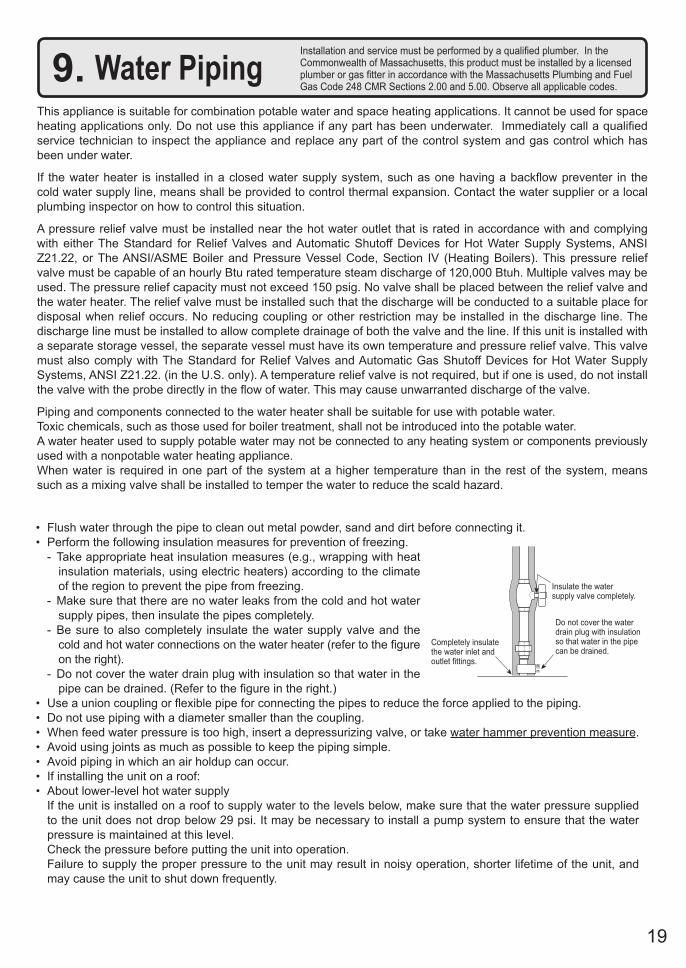
- Be sure to also completely insulate the water supply valve and the cold and hot water connections on the water heater (refer to the figure on the right).
- Do not cover the water drain plug with insulation so that water in the pipe can be drained. (Refer to the figure in the right.)
• Use a union coupling or flexible pipe for connecting the pipes to reduce the force applied to the piping.• Do not use piping with a diameter smaller than the coupling.• When feed water pressure is too high, insert a depressurizing valve, or take water hammer prevention measure.• Avoid using joints as much as possible to keep the piping simple.• Avoid piping in which an air holdup can occur.• If installing the unit on a roof:• About lower-level hot water supply If the unit is installed on a roof to supply water to the levels below, make sure that the water pressure supplied
to the unit does not drop below 29 psi. It may be necessary to install a pump system to ensure that the water pressure is maintained at this level.
Check the pressure before putting the unit into operation. Failure to supply the proper pressure to the unit may result in noisy operation, shorter lifetime of the unit, and
may cause the unit to shut down frequently.
Completely insulate the water inlet and outlet fittings.
Insulate the water supply valve completely.
Do not cover the water drain plug with insulation so that water in the pipe can be drained.
20
Supply water piping• Do not use PVC, iron, or any piping which has been
treated with chromates, boiler seal or other chemicals.• Mount a check valve and a shut off valve (near the inlet).• In order for the client to use the water heater
comfortably, 98.1 to 491 kPa (14 to 70 PSI) of pressure is needed from the water supply.
Be sure to check the water pressure. If the water pressure is low, the water heater cannot perform to its full capability, and may become a source of trouble for the client.
Drain piping• Expansion water may drop from the pressure
relief valve and wet the floor. If necessary, provide drain piping or use a drain
hose to remove the water.
Hot water piping• Do not use lead, PVC, iron or any piping which
has been treated with chromates, boiler seal or other chemicals.
• The longer the piping, the greater the heat loss. Try to make the piping as short as possible.
• Use mixing valves with low water resistance. Use shower heads with low pressure loss.
• If necessary, use a pump or other means to ensure that the supply water pressure to the inlet of the heater does not fall below 29 PSI when the maximum amount of water is being demanded. Also install a pressure meter on the inlet. If this is not done, local boiling will occur inside the water heater causing abnormal sounds and decreasing the durability of the heat exchanger.
Freeze Prevention• Do not install the water heater in a place where the inside/outside temperature is below 32°F (0°C).• Freezing is prevented within the device automatically unless the outside temperature without wind
is below 32°F (0°C). * The room temperature must be greater than 32°F (0°C) to prevent freezing and the room inside must not have negative pressure.• The freeze prevention heaters will not prevent the plumbing external to the unit from freezing.
Protect this plumbing with insulation, heat tape or electric heaters, solenoids, or pipe covers.• In order for the freeze prevention heaters to operate, the water heater must have power at all times.
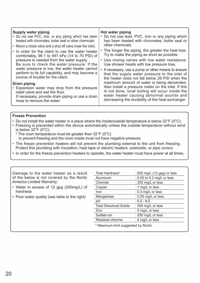
Total Hardness* : 200 mg/L (12 gpg) or lessAluminum : 0.05 to 0.2 mg/L or lessChloride : 250 mg/L or lessCopper : 1 mg/L or lessIron : 0.3 mg/L or lessManganese : 0.05 mg/L or lesspH : 6.5 - 8.5Total Dissolved Solids : 500 mg/L or lessZinc : 5 mg/L or lessSulfate ion : 250 mg/L or less Residual chlorine : 4 mg/L or less* Maximum limit suggested by Noritz.
Damage to the water heater as a result of the below is not covered by the Noritz America Limited Warranty.• Water in excess of 12 gpg (200mg/L) of
hardness • Poor water quality (see table to the right)
21
Water Treatment
Water Treatment System
City Water Supply
Hot Water to Fixtures
Shutoff ValvePressure
ReliefValve
Drain
Cold to Water
Heater
Optional Sediment
Filter
Water Treatment Device
Shutoff Valve
Type of Water Hardness Level Treatment Device* Flush Frequency**
Soft0-1 gpg
1-3 gpg
(0-17 mg/L)None None
Slightly Hard
(17-51 mg/L)None None
Moderately Hard
Hard
3-7 gpg
(51-120 mg/L)H2Flow or
ScaleShield
H2Flow or
ScaleShield
Once a Year*** or
Flashing the error code****
Once a Year*** or
Flashing the error code****
Once a Year*** or
Flashing the error code****
Once a Year*** or
Flashing the error code****
7-10 gpg
(120-171 mg/L)
Very Hard10-12 gpg
(120-200 mg/L)H2Flow or
Water Softener
H2Flow or
Water SoftenerExtremely
Hard> 12 gpg
(> 200 mg/L)
Residential Use Treatment Guidelines
NORITZCondensing
Tankless GasWater Heater
* When selecting a treatment device, you must consult with the device’s spec sheet and installation manual for guidelines and limitations. Not all water supplies are compatible - a water test may be required.
** Install Noritz Isolation Valves to allow for flushing.
*** Flushing is required if a water treatment
device is not installed.
**** The error code " " will be flashing in the
Display Window.
= 1, 2, 3, 4, F
# = 1, 2, 3, 4, 5, 6, 7, 8, 9, A, b, C, d, E, F
▲The illustration is an example. Please check with the actual water heater about the position of piping, and form.
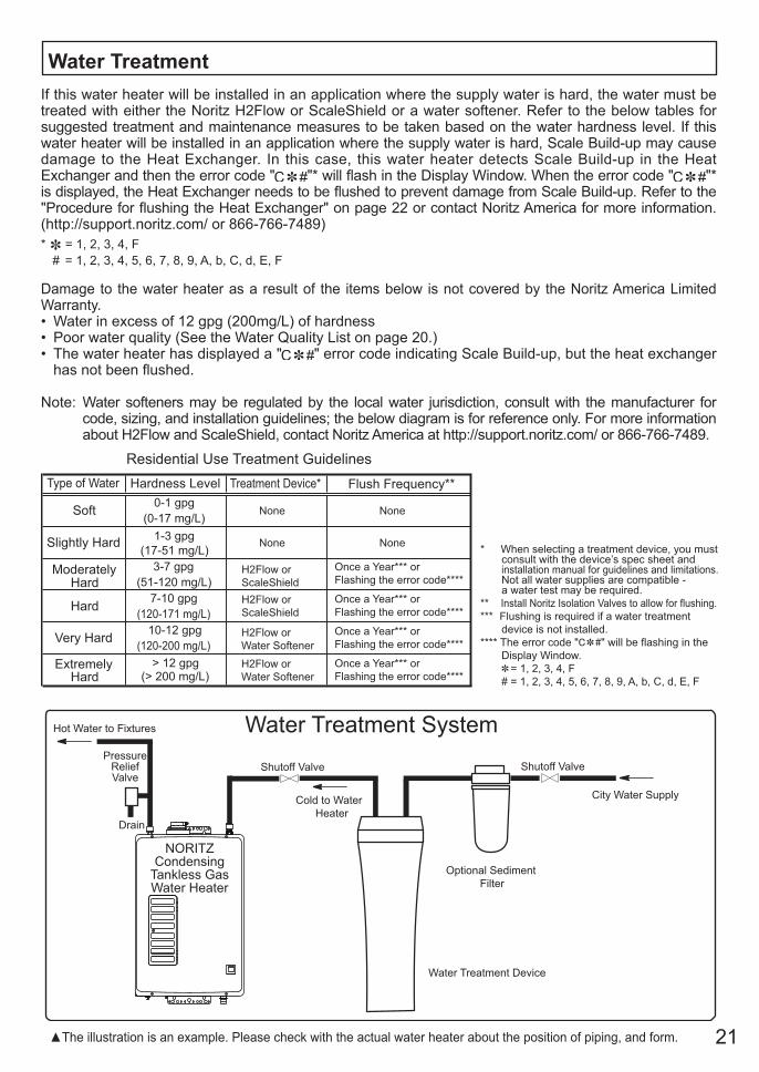
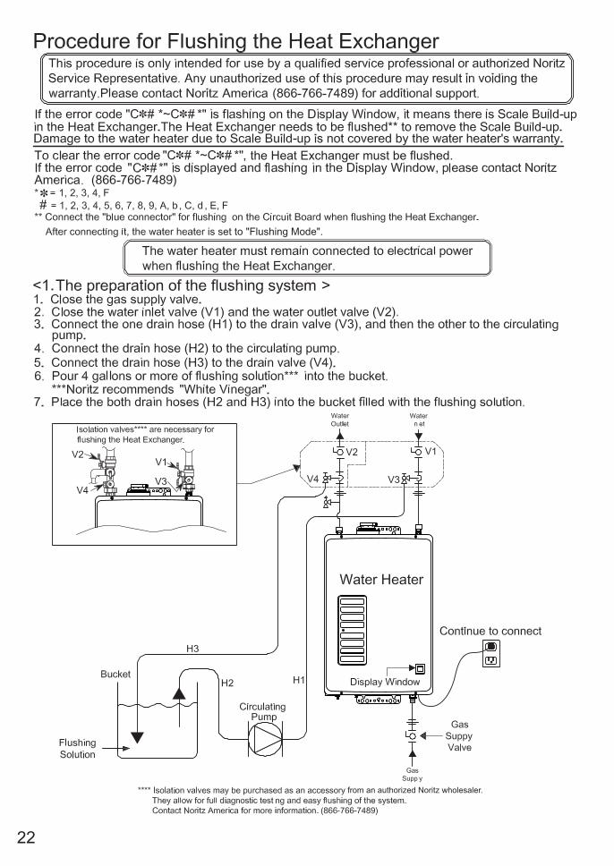
If this water heater will be installed in an application where the supply water is hard, the water must be treated with either the Noritz H2Flow or ScaleShield or a water softener. Refer to the below tables for suggested treatment and maintenance measures to be taken based on the water hardness level. If this water heater will be installed in an application where the supply water is hard, Scale Build-up may cause damage to the Heat Exchanger. In this case, this water heater detects Scale Build-up in the Heat Exchanger and then the error code " "* will flash in the Display Window. When the error code " "* is displayed, the Heat Exchanger needs to be flushed to prevent damage from Scale Build-up. Refer to the "Procedure for flushing the Heat Exchanger" on page 22 or contact Noritz America for more information. (http://support.noritz.com/ or 866-766-7489)
Damage to the water heater as a result of the items below is not covered by the Noritz America Limited Warranty.• Water in excess of 12 gpg (200mg/L) of hardness • Poor water quality (See the Water Quality List on page 20.)• The water heater has displayed a " " error code indicating Scale Build-up, but the heat exchanger
has not been flushed.
Note: Water softeners may be regulated by the local water jurisdiction, consult with the manufacturer for code, sizing, and installation guidelines; the below diagram is for reference only. For more information about H2Flow and ScaleShield, contact Noritz America at http://support.noritz.com/ or 866-766-7489.
* = 1, 2, 3, 4, F # = 1, 2, 3, 4, 5, 6, 7, 8, 9, A, b, C, d, E, F
22
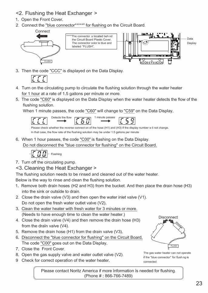
the Heat Exchanger must be flushed.
is set to "Flushing Mode".
located
from an authorized Noritz wholesaler.
23
the Heat Exchanger must be flushed.
is set to "Flushing Mode".
located
from an authorized Noritz wholesaler.
24
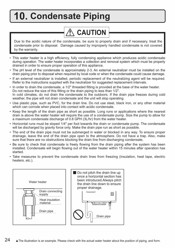
• This water heater is a high efficiency, fully condensing appliance which produces acidic condensate during operation. The water heater incorporates a collection and removal system which must be properly drained in order to ensure proper operation of this appliance.
• The pH level of the condensate is approximately 2-3. An external neutralizer must be installed on the drain piping prior to disposal when required by local code or when the condensate could cause damage.
• If an external neutralizer is installed, periodic replacement of the neutralizing agent will be required. Refer to the instructions supplied with the neutralizer for suggested replacement intervals.
• In order to drain the condensate, a 1/2" threaded fitting is provided at the base of the water heater. Do not reduce the size of this fitting or the drain piping to less than 1/2". In cold climates, do not drain the condensate to the outdoors. If the drain pipe freezes during cold
weather, the pipe will not drain condensate and the unit will stop operating.• Use plastic pipe, such as PVC, for the drain line. Do not use steel, black iron, or any other material
which can corrode when placed into contact with acidic condensate.• Keep the length of the drain pipe as short as possible. Long runs or applications where the nearest
drain is above the water heater will require the use of a condensate pump. Size the pump to allow for a maximum condensate discharge of 0.8 GPH (3L/hr) from the water heater.
• Horizontal runs must be sloped 1/4" per foot towards the drain or condensate pump. The condensate will be discharged by gravity force only. Make the drain pipe run as short as possible.
• The end of the drain pipe must not be submerged in water or blocked in any way. To ensure proper drainage, leave the end of the drain pipe open to the atmosphere. Do not have a trap. Also, make sure that there are no obstructions blocking the drain line from discharging condensate.
• Be sure to check that condensate is freely flowing from the drain piping after the system has been installed. Condensate will begin flowing out of the water heater within 15 minutes after operation has started.
• Take measures to prevent the condensate drain lines from freezing (insulation, heat tape, electric heaters, etc.).
10. Condensate Piping
Drain pipe
Drain pipe
Drain connectingsupply
Heat insulation material
Water heater
Do not pitch the drain line up once a horizontal section has been introduced.Always pitch the drain line down to ensure proper drainage.
Due to the acidic nature of the condensate, be sure to properly drain and if necessary, treat the condensate prior to disposal. Damage caused by improperly handled condensate is not covered by the warranty.
CAUTION
▲The illustration is an example. Please check with the actual water heater about the position of piping, and form.
25
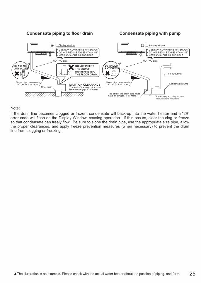
Note:If the drain line becomes clogged or frozen, condensate will back-up into the water heater and a "29" error code will flash on the Display Window, ceasing operation. If this occurs, clear the clog or freeze so that condensate can freely flow. Be sure to slope the drain pipe, use the appropriate size pipe, allow the proper clearances, and apply freeze prevention measures (when necessary) to prevent the drain line from clogging or freezing.
▲The illustration is an example. Please check with the actual water heater about the position of piping, and form.
Condensate piping to floor drain Condensate piping with pump
Slope pipe downwards 1/4" per foot. or more.
The end of the drain pipe musthave an air gap. 1” or more.
USE NON-CORROSIVE MATERIALS
DO NOT REDUCE TO LESS THAN 1/2”
KEEP AS SHORT AS POSSIBLE
1/2" PVC pipe
Display window
Floor drain* MAINTAIN CLEARANCE
DO NOT ADDANY VALVES
DO NOT INSERT THE END OFDRAIN PIPE INTO THE FLOOR DRAIN.
Slope pipe downwards 1/4" per foot. or more.
The end of the drain pipe musthave an air gap. 1” or more.
USE NON-CORROSIVE MATERIALS
DO NOT REDUCE TO LESS THAN 1/2”
KEEP AS SHORT AS POSSIBLE
1/2" PVC pipe
Display window
DO NOT ADDANY VALVES
* Install tubing according to pump
manufacturer's instructions.
3/8" ID tubing*
Condensate pump
26
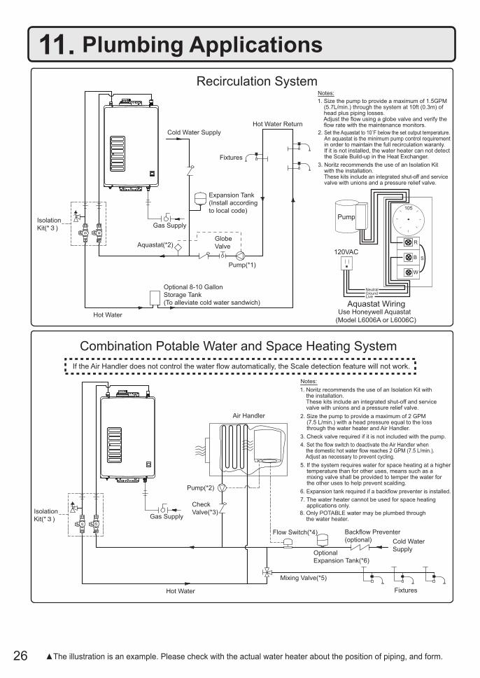
Recirculation System
Combination Potable Water and Space Heating System
If the Air Handler does not control the water flow automatically, the Scale detection feature will not work.
Cold Water Supply
Isolation
Kit(* ) Gas Supply
Aquastat(*2)
Hot Water
Optional 8-10 Gallon
Storage Tank
(To alleviate cold water sandwich)
Globe
Valve
Pump(*1)
Expansion Tank
(Install according
to local code)
Fixtures
Hot Water Return
Backflow Preventer
(optional)
Check
Valve(*3)
Cold Water
SupplyOptional
Expansion Tank(*6)
Mixing Valve(*5)
Hot Water
Pump(*2)
Flow Switch(*4)
Fixtures
Air Handler
Notes:
1. Noritz recommends the use of an Isolation Kit with the installation. These kits include an integrated shut-off and service valve with unions and a pressure relief valve.
2. Size the pump to provide a maximum of 2 GPM (7.5 L/min.) with a head pressure equal to the loss through the water heater and Air Handler.
3. Check valve required if it is not included with the pump.
4. Set the flow switch to deactivate the Air Handler when the domestic hot water flow reaches 2 GPM (7.5 L/min.). Adjust as necessary to prevent cycling.
5. If the system requires water for space heating at a higher temperature than for other uses, means such as a mixing valve shall be provided to temper the water for the other uses to help prevent scalding.
7. The water heater cannot be used for space heating applications only.
6. Expansion tank required if a backflow preventer is installed.
8. Only POTABLE water may be plumbed through the water heater.
R
B
W
Pump
120VAC
105
NeutralGroundLive
S
Notes:
Use Honeywell Aquastat
(Model L6006A or L6006C)
Aquastat Wiring
1. Size the pump to provide a maximum of 1.5GPM (5.7L/min.) through the system at 10ft (0.3m) of head plus piping losses. Adjust the flow using a globe valve and verify the flow rate with the maintenance monitors.
2. Set the Aquastat to 10˚F below the set output temperature. An aquastat is the minimum pump control requirement in order to maintain the full recirculation waranty. If it is not installed, the water heater can not detect the Scale Build-up in the Heat Exchanger.
3. Noritz recommends the use of an Isolation Kit with the installation. These kits include an integrated shut-off and service valve with unions and a pressure relief valve.
Isolation
Kit(* ) Gas Supply
11. Plumbing Applications
▲The illustration is an example. Please check with the actual water heater about the position of piping, and form.
27
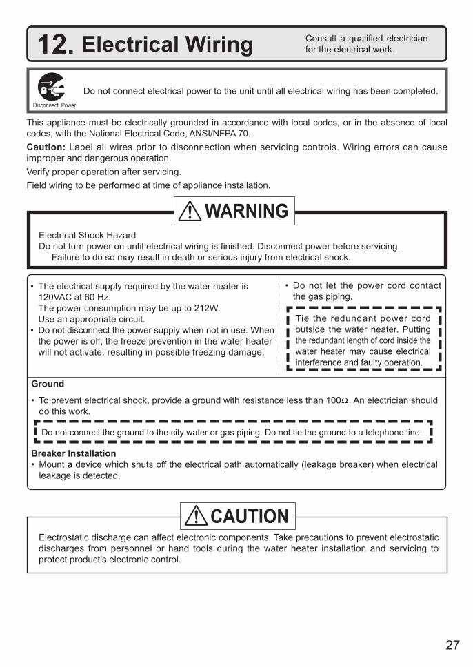
Do not connect electrical power to the unit until all electrical wiring has been completed.
Consult a qualified electrician for the electrical work.12. Electrical Wiring
This appliance must be electrically grounded in accordance with local codes, or in the absence of local codes, with the National Electrical Code, ANSI/NFPA 70.Caution: Label all wires prior to disconnection when servicing controls. Wiring errors can cause improper and dangerous operation.Verify proper operation after servicing.Field wiring to be performed at time of appliance installation.
• The electrical supply required by the water heater is 120VAC at 60 Hz.
The power consumption may be up to 212W. Use an appropriate circuit.• Do not disconnect the power supply when not in use. When
the power is off, the freeze prevention in the water heater will not activate, resulting in possible freezing damage.
• Do not let the power cord contact the gas piping.
Tie the redundant power cord outside the water heater. Putting the redundant length of cord inside the water heater may cause electrical interference and faulty operation.
Disconnect Power
Electrical Shock HazardDo not turn power on until electrical wiring is finished. Disconnect power before servicing. Failure to do so may result in death or serious injury from electrical shock.
WARNING
Electrostatic discharge can affect electronic components. Take precautions to prevent electrostatic discharges from personnel or hand tools during the water heater installation and servicing to protect product’s electronic control.
CAUTION
Ground
• To prevent electrical shock, provide a ground with resistance less than 100 . An electrician should do this work.
Do not connect the ground to the city water or gas piping. Do not tie the ground to a telephone line.
Breaker Installation• Mount a device which shuts off the electrical path automatically (leakage breaker) when electrical
leakage is detected.
28
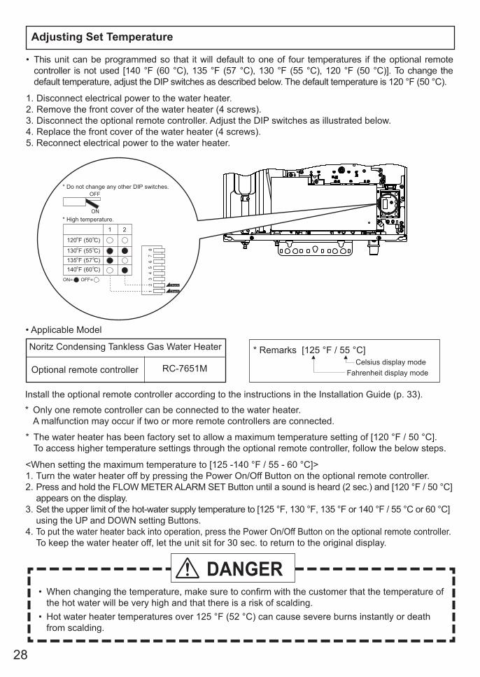
Adjusting Set Temperature
• Applicable Model
Install the optional remote controller according to the instructions in the Installation Guide (p. 33).
* Only one remote controller can be connected to the water heater. A malfunction may occur if two or more remote controllers are connected.
Optional remote controller RC-7651M
Noritz Condensing Tankless Gas Water Heater
* The water heater has been factory set to allow a maximum temperature setting of [120 °F / 50 °C]. To access higher temperature settings through the optional remote controller, follow the below steps.
<When setting the maximum temperature to [125 -140 °F / 55 - 60 °C]>1. Turn the water heater off by pressing the Power On/Off Button on the optional remote controller.2. Press and hold the FLOW METER ALARM SET Button until a sound is heard (2 sec.) and [120 °F / 50 °C]
appears on the display.3. Set the upper limit of the hot-water supply temperature to [125 °F, 130 °F, 135 °F or 140 °F / 55 °C or 60 °C]
using the UP and DOWN setting Buttons.4. To put the water heater back into operation, press the Power On/Off Button on the optional remote controller. To keep the water heater off, let the unit sit for 30 sec. to return to the original display.
• When changing the temperature, make sure to confirm with the customer that the temperature of the hot water will be very high and that there is a risk of scalding.
• Hot water heater temperatures over 125 °F (52 °C) can cause severe burns instantly or death from scalding.
DANGER
* Remarks [125 °F / 55 °C]
Fahrenheit display modeCelsius display mode
* Do not change any other DIP switches.
* High temperature.
1 2
ON= OFF=
120 F (50 C)
135 F (57 C)130 F (55 C)
140 F (60 C)
Check
Check
• This unit can be programmed so that it will default to one of four temperatures if the optional remote controller is not used [140 °F (60 °C), 135 °F (57 °C), 130 °F (55 °C), 120 °F (50 °C)]. To change the default temperature, adjust the DIP switches as described below. The default temperature is 120 °F (50 °C).
1. Disconnect electrical power to the water heater.2. Remove the front cover of the water heater (4 screws).3. Disconnect the optional remote controller. Adjust the DIP switches as illustrated below.4. Replace the front cover of the water heater (4 screws).5. Reconnect electrical power to the water heater.
29
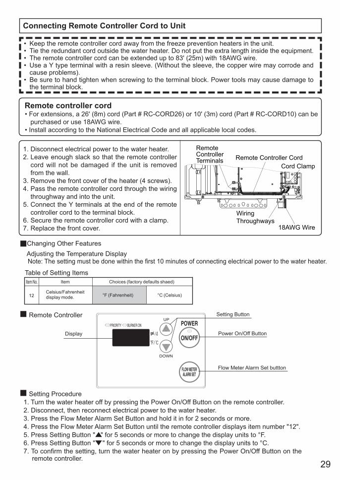
Connecting Remote Controller Cord to Unit
• Keep the remote controller cord away from the freeze prevention heaters in the unit.• Tie the redundant cord outside the water heater. Do not put the extra length inside the equipment.• The remote controller cord can be extended up to 83' (25m) with 18AWG wire.• Use a Y type terminal with a resin sleeve. (Without the sleeve, the copper wire may corrode and
cause problems).• Be sure to hand tighten when screwing to the terminal block. Power tools may cause damage to
the terminal block.
Changing Other Features Adjusting the Temperature Display Note: The setting must be done within the first 10 minutes of connecting electrical power to the water heater.
Table of Setting ItemsItem No. Item Choices (factory defaults shaed)
12Celsius/Fahrenheit display mode. °F (Fahrenheit) °C (Celsius)
Display Power On/Off Button
Flow Meter Alarm Set buttton
Setting Button
Setting Procedure1. Turn the water heater off by pressing the Power On/Off Button on the remote controller.2. Disconnect, then reconnect electrical power to the water heater.3. Press the Flow Meter Alarm Set Button and hold it in for 2 seconds or more.4. Press the Flow Meter Alarm Set Button until the remote controller displays item number "12".5. Press Setting Button " " for 5 seconds or more to change the display units to °F.6. Press Setting Button " " for 5 seconds or more to change the display units to °C.7. To confirm the setting, turn the water heater on by pressing the Power On/Off Button on the
remote controller.
Remote Controller
Remote controller cord• For extensions, a 26' (8m) cord (Part # RC-CORD26) or 10' (3m) cord (Part # RC-CORD10) can be
purchased or use 18AWG wire.• Install according to the National Electrical Code and all applicable local codes.
1. Disconnect electrical power to the water heater.2. Leave enough slack so that the remote controller
cord will not be damaged if the unit is removed from the wall.
3. Remove the front cover of the heater (4 screws).4. Pass the remote controller cord through the wiring
throughway and into the unit.5. Connect the Y terminals at the end of the remote
controller cord to the terminal block.6. Secure the remote controller cord with a clamp.7. Replace the front cover.
Remote Controller Cord
Wiring
Throughways18AWG Wire
Cord Clamp
RemoteControllerTerminals
30
(1) Open a hot water fixture and confirm that the Burner On lamp comes on, and that hot water is being produced. (If necessary, repeat until the air in the gas piping is bled out).* White smoke may be noticed from the exhaust vent during cold weather. However, this is not a
malfunction of the unit.* If an “11” error code appears on the Display Window, close a hot water fixture and then back
on again, and then open a hot water fixture again.(2) Using the optional remote controller, change the temperature setting on the remote controller and
check that the water temperature changes.
• If the water heater does not operate normally, refer to “Troubleshooting” in the Owner’s Guide.* After the trial operation, clean the filter in the cold water inlet.
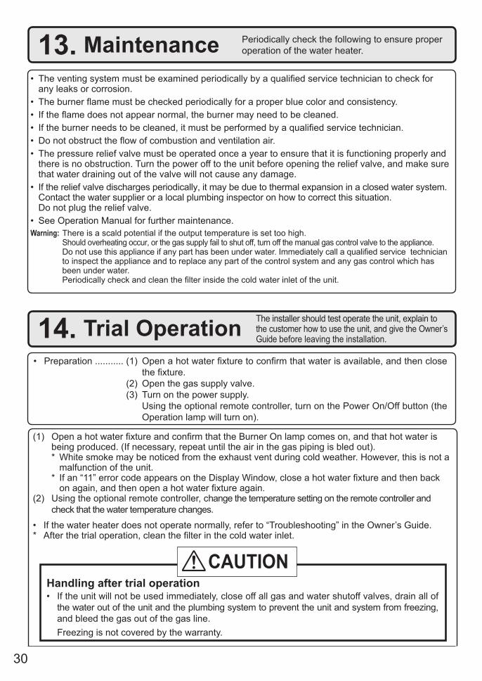
13. Maintenance Periodically check the following to ensure properoperation of the water heater.
• The venting system must be examined periodically by a qualified service technician to check for any leaks or corrosion.
• The burner flame must be checked periodically for a proper blue color and consistency. • If the flame does not appear normal, the burner may need to be cleaned.• If the burner needs to be cleaned, it must be performed by a qualified service technician.• Do not obstruct the flow of combustion and ventilation air.• The pressure relief valve must be operated once a year to ensure that it is functioning properly and
there is no obstruction. Turn the power off to the unit before opening the relief valve, and make sure that water draining out of the valve will not cause any damage.
• If the relief valve discharges periodically, it may be due to thermal expansion in a closed water system. Contact the water supplier or a local plumbing inspector on how to correct this situation.
Do not plug the relief valve.• See Operation Manual for further maintenance.Warning: There is a scald potential if the output temperature is set too high. Should overheating occur, or the gas supply fail to shut off, turn off the manual gas control valve to the appliance. Do not use this appliance if any part has been under water. Immediately call a qualified service technician
to inspect the appliance and to replace any part of the control system and any gas control which has been under water.
Periodically check and clean the filter inside the cold water inlet of the unit.
14. Trial Operation The installer should test operate the unit, explain tothe customer how to use the unit, and give the Owner’s Guide before leaving the installation.
• Preparation ........... (1) Open a hot water fixture to confirm that water is available, and then close the fixture.
(2) Open the gas supply valve. (3) Turn on the power supply. Using the optional remote controller, turn on the Power On/Off button (the
Operation lamp will turn on).
Handling after trial operation• If the unit will not be used immediately, close off all gas and water shutoff valves, drain all of
the water out of the unit and the plumbing system to prevent the unit and system from freezing, and bleed the gas out of the gas line.
Freezing is not covered by the warranty.
CAUTION
31
Lighting InstructionsThis water heater does not have a pilot. It is equipped with an ignition device that automatically lights the burner. Do not try to light the burner by hand. 1. Read the safety information in the installation manual or on the side of the water heater. 2. Turn off all electrical power to the unit. 3. Do not attempt to light the burner by hand. 4. Turn the gas control manual valve (external to the unit) clockwise to the off position. 5. Wait five minutes to clear out any gas. If the smell of gas remains, stop, and follow the instructions
on page 3 of Owner's Guide. 6. Turn the gas control manual valve counterclockwise to the on position. 7. Turn on electric power to the unit. 8. The unit will now operate whenever hot water is called for. If the unit will not operate, follow the
shutdown instructions and call a service technician.
Shutdown Instructions1. Stop any water demand.2. Turn off electric power. 3. Turn the gas control manual valve clockwise to the off position.
Should overheating occur, or the gas supply fail to shut off, turn off the manual control valve to the appliance.
A fire or explosion may result if these instructions are not followed, which may cause lose of life, personal injury or property damage.
WARNING
32
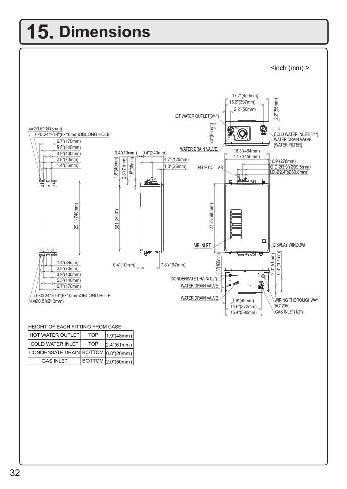
15. Dimensions
AIR INLET
FLUE COLLAR
DISPLAY WINDOW
COLD WATER INLET(3/4")
HOT WATER OUTLET(3/4")
WATER DRAIN VALVE
WATER DRAIN VALVE(WATER FILTER)
WATER DRAIN VALVE
CONDENSATE DRAIN(1/2")
WATER DRAIN VALVE
GAS INLET(1/2")
(AC120V)WIRING THOROUGHWAY
HOT WATER OUTLET TOP 1.9"(48mm)
COLD WATER INLET TOP 2.4"(61mm)
CONDENSATE DRAIN BOTTOM 0.8"(20mm)
GAS INLET BOTTOM 2.0"(50mm)
HEIGHT OF EACH FITTING FROM CASE
10.9"(278mm)
27.2
"(690m
m)
18.3"(464mm)17.7"(450mm)
I.D.Ø2.4"(Ø60.8mm)O.D.Ø3.9"(Ø99.5mm)
17.7"(450mm)
15.6"(397mm)
2.2
"(55m
m)
2.2"(56mm)
3.3
"(83m
m)
4.7"(120mm)
1.6
"(40m
m)
661
(26.0
")
0.4"(10mm)
2.8
"(71m
m)
9.4"(240mm)0.4"(10mm)
1.0"(25mm)
7.8"(197mm)
1.5"
(38m
m)
1.9"(49mm)
14.6"(372mm)
15.4"(390mm)
6.6"
(168
mm
)
2.0
"(51m
m)
6.3
"(161m
m)
29.1
"(740m
m)
1.4"(36mm)
2.8"(70mm)
3.9"(100mm)
5.5"(140mm)
6.7"(170mm)
1.4"(36mm)
2.8"(70mm)
3.9"(100mm)
5.5"(140mm)
6.7"(170mm)
6×0.24"×0.4"(6×10mm)OBLONG HOLE
6×0.24"×0.4"(6×10mm)OBLONG HOLE4×Ø0.5"(Ø13mm)
4×Ø0.5"(Ø13mm)
<inch (mm) >
33
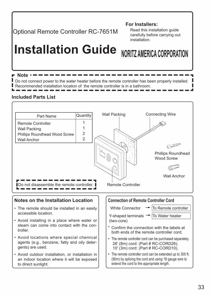
Included Parts List
Optional Remote Controller RC-7651M
Installation Guide
For Installers: Read this installation guide
carefully before carrying out installation.
NORITZ AMERICA CORPORATION
NoteDo not connect power to the water heater before the remote controller has been properly installed. Recommended installation location of the remote controller is in a bathroom.
Do not disassemble the remote controller.
Wall Packing Connecting Wire
Remote Controller
Phillips Roundhead Wood Screw
Wall Anchor
Part Name
Remote ControllerWall PackingPhillips Roundhead Wood ScrewWall Anchor
Quantity
1122
Notes on the Installation Location• The remote should be installed in an easily
accessible location.
• Avoid installing in a place where water or steam can come into contact with the con-troller.
• Avoid locations where special chemical agents (e.g., benzene, fatty and oily deter-gents) are used.
• Avoid outdoor installation, or installation in an indoor location where it will be exposed to direct sunlight.
Connection of Remote Controller Cord White Connector To Remote controller Y-shaped terminals To Water heater (two-core)
* Confirm the connection with the labels at both ends of the remote controller cord.
• The remote controller cord can be purchased separately. 26' (8m) cord: (Part # RC-CORD26). 10' (3m) cord: (Part # RC-CORD10). • The remote controller cord can be extended up to 300 ft.
(90m) by splicing the cord and using 18 gauge wire to extend the cord to the appropriate length.
34
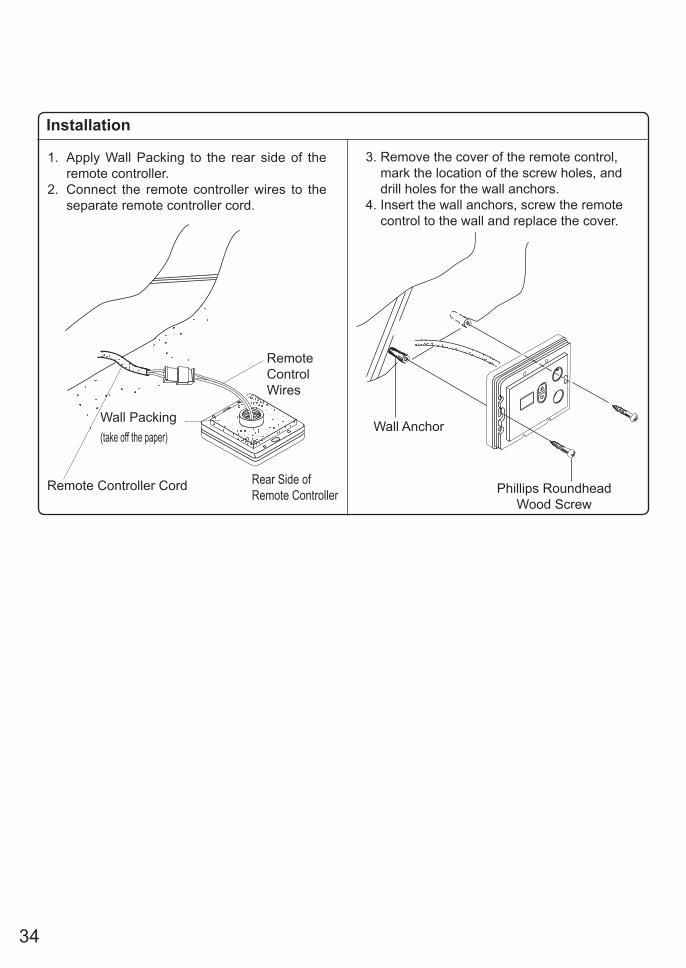
Installation
1. Apply Wall Packing to the rear side of the remote controller.
2. Connect the remote controller wires to the separate remote controller cord.
Phillips RoundheadWood Screw
Wall Anchor
3. Remove the cover of the remote control, mark the location of the screw holes, and drill holes for the wall anchors. 4. Insert the wall anchors, screw the remote control to the wall and replace the cover.
Remote Controller Cord
Wall Packing(take off the paper)
RemoteControlWires
Rear Side of Remote Controller