Embed Size (px)
Citation preview

1
LECTURE 6: Pneumatic controls, PLC's, Ladder Logic
Pneumatic Controls Pneumatic controls are very common in industrial use, primarily for applications that require a fixed distance travel of or reciprocation of objects. Examples include transfer of materials between conveyors, clamping objects for assembly or testing, punch presses etc. Compressed air is used to generate the actuating action.
Elements of pneumatic systems: (1) Valves: Valves are used to control the direction and quantity of air flow between the tubes (or lines) of a pneumatic circuit. Most valves are constructed to function in two-positions. Each position opens one or more paths for free air flow and shuts off the others. Depending upon the position, the flow of air is controlled. The two most common valves are 3/2 and 5/2 valves. The first number denotes the number of air connections, and the second number the number of air flow paths. Figure 5.1 shows a schematic representation of these valves. Each valve is represented by two abutting rectangles, and the external air connections. Moving the valve from one position to the other can be visualized by sliding the corresponding rectangle over the other one, keeping the air lines fixed. Moving valves between the two positions can be done in many different ways. Figure 5.2 shows some example schematics.
a 3/2 valve a 5/2 valve Figure 5.1. Common pneumatic valves
return spring pneumatic
push buttonfoot pedal
solenoid (electrical) roller (mechanical)
Figure 5.2. Different actuation methods for valves
NOTES______________________________________________________________

2
(2) Cylinders: are actually piston cylinder assemblies. These are the elements that cause motion, and do the real work that is to be done. The valves are merely used to create the logic, which determines the sequence in which the various cylinders move. Two common types of cylinders include spring-return type, and double-acting type. These are shown in the schematics below. The pistons move in or out. Apart from the fully extended and fully retracted positions of the piston, there is no intermediate position control in piston motion. (3) Compressors: Compressors provide the high pressure air that is delivered to the cylinders in order to make the pistons move. Most compressors are turbines that are run using electric motors. In pneumatic circuits, it is common to omit the compressor and just represent the compressed air supply by the symbol in the figure below.
•
double -acting
spring-return
air supply
vent to atmosphere (air discharge)
Figure 5.3. Cylinder and air supply symbols Pneumatic circuits are built of these basic elements to create the logic of a required set of motions. The two positions of the piston in a cylinder are usually shown by +/- signs. The sequence of desired positions of cylinders is shown as a list of symbols as in figure 5.4, which shows a simple pneumatic circuit.
NOTES______________________________________________________________

3
•
•
Start
• VA
A+A-
A- +
Figure 5.4. A Pneumatic circuit to actuate cylinder A as : START, A+, A-
The Cascade method The cascade method is a simple procedure to create pneumatic circuits involving many cylinders to generate a sequence of actions. We illustrate the method by the use of a simple example. Example: A small punch press is operated as follows. The part is clamped in position; the press punches the part; the clamp is released; and the part is removed from the table. The operations are achieved using three pneumatic cylinders, A, B, C. The operation sequence can be described as: START, A+, B+, B-, A-, C+, C- What do cylinders A, B, and C do? We describe the cascade method first, and then build the circuit for the example. (1) The cylinder action sequence is listed.
NOTES______________________________________________________________

4
(2) The sequence is partitioned into groups, such that no letter is repeated in any group. The aim is to minimize the number of groups. (3) If the last group has no letters in common with the first, it can be merged into the first group. (4) Each cylinder is double-acting. (5) Each cylinder is controlled by a 5/2 valve, actuated on both ends pneumatically (pneumatic valve actuation lines are also called pilot lines). (6) Each cylinder is associated with two limit valves, one each at the + and - positions. (7) Each group is assigned a manifold line. A manifold line is simply a tube with multiple outlets. When the group is active, the manifold line associated with it is pressurized. At all other times, it is open to the atmosphere. The manifold line connects to the limit valves associated with the cylinders. This ensures that the pilot valves (the 5/2 valves) never get contradictory signals (i.e. both the pilot lines of the valve are never at the same pressure.) (8) The air pressure in the manifolds is controlled by 5/2 valves called group valves. The total number of group valves is one less than the total number of groups. We now return to our example, where we need the sequence: START, A+, B+, B-, A-, C+, C- Break it down into groups: START, A+, B+ / B-, A-, C+ / C- GRP 1 GRP 2 GRP 3 Since GRP 3 has no letter in common with GRP 1, we can include it in GRP 1: START, A+, B+ / B-, A-, C+ / C- GRP 1 GRP 2 GRP 1 Locate the three cylinders, and draw all the required valves: Two limit valves (3/2) for each, one 5/2 actuating valve for each, one start valve (3/2), and since there are 2 groups, 2 manifold lines, and (2 -1 = 1) group valve. Note the following: • Limit valves a2, b2 and c1 get their air supply from manifold 1, while a1, b1 and c2 get their air supply from manifold 2 (according to step 7 above).
NOTES______________________________________________________________

5
• Pilot line 1 of the group valve will be activated by c2, after cylinder action C+, which marks the transition from GRP 2 to GRP 1. • Pilot line 2 of the group valve is activated by b2, after cylinder action B+ Why ? • Cylinder X is supplied actuation power via valve VX ( X = A, B, C). Note the configuration of the discharge lines in each of these valves. • Pilot line VA- is actuated via b1 (after B-). Why ? The various connections are now established to create the required logic. The final circuit is shown in figure 5.5 on the following page.
Some remarks While pneumatic actuators are very commonly used in industry, the use of purely pneumatic controls is reducing as more and more electronic controllers become popular in actuation. Most pneumatic manufacturers now produce electro-pneumatic components, such as cylinders with built-in electrical limit switches at the extreme positions, and solenoid activated multiple route valves. The logic for controlling these electro-pneumatic circuits is executed using programmable logic controllers, which we shall study next.
NOTES______________________________________________________________

6
Sta
rt
-+
-+
-+
•
•
•
•
A
a1a2
B
b1b2
C
c1c2
-+
VC+
-VB
-+
VA
1 2
21
Cas
cade
circ
uit f
or: S
TAR
T, A
+, B
+, B
-, A
-, C
+, C
-

7
NOTES______________________________________________________________
Programmable Logic Controllers The initial automation of factories was done using relays. The most complicated of control logic was simplified as far as possible (e.g. using Karnaugh maps, which we shall study later), and the resulting expressions were implemented to control shop-floor switching of actuators by using circuits of relays. A common device was relay-panels, which provided an array of relays that could be connected using wires according to the required logic. By the late 1960's, the car industries in the US were searching for alternatives to relay-panels. The reasons were simple: firstly, relay boards were bulky and cumbersome. Secondly, they were difficult to debug or modify, and time-consuming to wire and document. Thirdly, with the onset of the use of computers, there was no elegant way to link relay-panels with these expensive mini-computers that were gaining acceptance as processors of a lot of factory information (the linking of computers with equipment was mostly for data acquisition and supervisory control.) This problem was solved by the development of programmable controllers (or, more popularly, programmable logic controllers: PLC's.) The PLC's were solid-state electronic devices developed specifically to operate on the shop-floor. Apart form their advantages over relay-panels, they offered significant advantages over any other control technique. The PLC was rugged enough to perform reliably in the plant floor environment - with extreme temperatures and humidity, airborne dust and particulates, widely fluctuating voltages, and prevalence of radio-frequencies and electro-magnetic interference. Interface to a host computer was straightforward. Apart from the design advantages, the most significant reason for the tremendous success of PLC's was the programming language chosen: relay ladder logic. The close correspondence of ladder logic to relay circuits was the reason for the acceptance of PLC's on the shop-floor by control engineers, system operators and technicians. Ladder logic provided a pictorial programming interface (rather than a symbolic one like FORTRAN, or Pascal) with graphical representations for relays and switches.
To begin with, what does a PLC look like ?
It looks like a box, with many little electrical connecting points along its sides. The following schematic
sketch demonstrates a simple PLC.

8
NOTES______________________________________________________________
A/C
220Vinput 0
input 1input 2
input 3input 4
input 5input 6
Power supply wire
O u t p u t s
Box with Computer (controller)
data communication wire
Figure 5.6 Schematic sketch of a simple PLC
Some more complex PLC’s look a little different, but EVERY PLC will have the following components:
1. A set of electrical connections corresponding to INPUTS. Each connection has a unique INPUT
number.
2. A set of electrical connections, corresponding to OUTPUTS. Each connection has a unique OUTPUT
number.
3. A Controller, which is a simple form of a computer.
What can a PLC do ?
Execute logic to control equipment based on some conditions which are reported by sensors, or switches.
This needs some explanation. Consider that there is some equipment in a factory which needs to be
controlled by some actuators. For example, when a part is loaded on a machine, we would like two
pneumatic cylinders to extend and hold the part into a fixed position. Then we would like to turn on a
motor, which operates a drill to make holes in the part. When the drilling is done, we would like to switch
off the drill, and then release the cylinders, to remove the part.

9
NOTES______________________________________________________________
Imagine that when a part is put on the machine table, a photo-sensor is activated, giving us an indication
that the operation sequence described above must begin. Then we can use a PLC to operate all this
machinery.
First, the photosensor gives the signal of part arrival: it is therefore an input to our logic, indicating that
operations must begin. Such sensors are usually connected to the INPUT connections on the PLC (since
these sensors are external to the PLC, they are also called EXTERNAL INPUTS).
The logical sequence of operations: Turn Cylinder 1 ON Turn Cylinder 2 ON Turn Drill Motor ON
Wait (delay) till Drilling is done Turn Drill Motor OFF Turn Cylinder 2 OFF Turn Cylinder 1
OFF must now be executed. All this is information is very systematic, and therefore we can program it into
a computer to perform the operation. This information is then EXECUTED (just like a computer
RUNNING a PROGRAM) by the computer inside the PLC. This computer is called a CONTROLLER
(since it controls the logic).
Thus, when the EXTERNAL INPUT connected to the Photo Sensor is turned ON, the PLC controller
senses that actions must begin, and it first turns a SPECIFIED OUTPUT terminal (for example, Output 1),
ON. This means that at the electrical connection corresponding to Output 1, the voltage level, which was
0volts before, is now turned HIGH (example, 24 Volts). Of course, we had connected this Output 1
connection with a wire to a solenoid valve controlling the Cylinder 1. Thus Cylinder 1 will now turn ON.
Again, since the terminal Output 1 is connected to a device (in this case, a solenoid) outside the PLC, we
call it an EXTERNAL OUTPUT terminal.
Similarly, we had connected (external) Output 2 to a solenoid controlling Cylinder 2, and Output 3 to the
motor driving the Drilling Machine. Thus, the CONTROLLER, in sequence specified by the LOGIC
PROGRAMMED by you, controls the External Outputs to go ON and OFF. And accordingly, the different
actuators connected to the External Outputs are turned ON and OFF.
Can the PLC control many different actuators? Yes ! It can control as many actuators as it has External
Output terminals.
What kind of logical sequences of operations (including repeating actions, or loops) can the PLC control?
Many, and we will now learn these.
Example 1:

10
NOTES______________________________________________________________
Let’s start with the simplest example. In our factory is a robot, which picks up heavy metal parts from one
place, and puts them in another place. When the robot is working, it is not safe for humans to go near it,
since there could be an accident. Therefore, to warn the human operator that they are too close to the
operating robot, we need to install a warning light.
On the floor close to the Robot’s operational area, we put a pressure sensitive mat. This mat has a pressure
sensor, so when the load on top of it is increased (for example, when a human steps on the mat) then the
pressure switch is activated and turns ON.
THE LOGIC:
When Pressure_Switch is ON, turn the Warning_Light ON.
(of course, when the pressure switch turns off again, that is, when the human goes away from the robot, the
warning light must also go off.)
STEP 1:
We write this logic into a PROGRAM (since the computer can only understand programs!).
STEP 2:
We load this program into the PLC.
STEP 3:
We connect the sensor output (in this case, the Output of the Pressure sensitive switch) to the External
Input terminal. Of course, we have more than one External Input terminals. Which one do we connect ?
The one we specified in our program !
STEP 4:
We connect the PLC External Output Terminal (specified by our program) to the Warning Light.
STEP 5:
Now, we EXECUTE the logic program on the PLC.
Physically, this configuration is as follows:

11
NOTES______________________________________________________________
pressure sensitive mat
robotwarning bulb
Sensor output, connected to PLC Input: 1
to PLC Output: 1
Figure 5.7. Schematic for example 1
Earlier, we said that we can PROGRAM the PLC to execute the logic. How do we do that? By using a
programming language called LADDER LOGIC.
Ladder logic is a very simple programming language. Every programming language (e.g., Visual C++,
Java, Visual Basic) has a syntax, or grammar, to write programs. Programs are a sequence of instructions.
Similarly, Ladder logic programs are a sequence of instructions. However, there are two important
differences:
1. Other programming languages usually require programming using text. On the other hand, ladder logic
is a picture-based language. All symbols in ladder logic are simple pictures.
2. In most programming languages, the instructions that make up a typical program are executed in
sequence (one after the other), until a specific statement, e.g. HALT, or EXIT is encountered, telling the
program to stop. In Ladder logic, there is no HALT instruction -- the program runs until you physically
terminate it. Also, every instruction in the ladder logic program is executed in PARALLEL (that is, at the
same time). After executing all the statements, they are executed again (in parallel, as before), and so on....
until the program is halted by an external command.

12
NOTES______________________________________________________________
There is a third difference: Ladder logic is much simpler than most other programming languages. Every
symbol in the syntax has a direct correspondence either to simple electrical switches, or to electronic
switches like timers or counters.
Shown below is the ladder logic program for the Robot warning light:
I:0/1 O:0/1
The program has five parts:
1. A Left vertical line
2. A Right vertical line
3. One horizontal line, with two symbols:
4. The symbol -| |- which signifies a switch, called I:0/1
5. The symbol -( )- which signifies the output relay, called O:0/1
Every ladder program has a single left-side vertical line, which we will interpret as an electrical line
which is connected to HIGH voltage.
Every ladder logic program has a right-side vertical line, which we will interpret as an electrical line that
is connected to GROUND (zero volts).
Each horizontal line in the program represents one instruction. In simple terms, the instruction can be
thought of as an “IF (condition(s)) THEN (action)” statement. In our program, there is only one
instruction:
IF (input switch I:0/1 is ON) THEN (output relay O:0/1 is ON).
Let’s look at the --| |-- symbol some more. Technically, it represents a switch, and is called an “EXAMINE
IF ON’ instruction. Another name for it is “NORMALLY OPEN” switch.
Imagine that it is indeed a switch, then the left side is directly connected to the left vertical line, and is
therefore at HIGH voltage. When the switch is OFF, the right side of this switch will be a ZERO voltage.

13
NOTES______________________________________________________________
Similarly, the --( )-- symbol represents an OUTPUT RELAY (or a COIL). From your high school physics,
you know that a relay is usually made up of a coil of conducting wire, and is quite similar to a solenoid in
structure.
There are two things to understand about the --( )-- symbols.
First, when the --| |-- switch is OFF, the voltage across the coil is ZERO, and so the OUTPUT Relay is
OFF. But when the --| |-- switch is ON, then the two terminals of the switch are electrically connected,
which means that the right side of the --| |-- switch is at HIGH voltage, and therefore the voltage across the
COIL is HIGH. This means that the COIL is turned ON.
Second, why is the output a COIL ? After all, if we are going to use this connection to turn ON (or OFF)
an actuator, we could just use a switch! The reason is that a typical PLC can control many different
actuators. Typical actuators on a shop floor may include Machine tools, Conveyors, Robots etc. Each of
these equipments requires high power, which means a lot of current to operate. If we use a switch to
directly turn on such a high power line, the connections will burn out very easily (due to sparking during
switching). Also, the single power supply line to the PLC may not be able to supply such a large amount of
current. Thus, the output is a relay, which can then be used to switch on a high power line, to operate the
machinery.
We now see how the single line of PROGRAMMED LOGIC works: If the INPUT SWITCH called I:0/1 is
turned ON, then the Output Coil called O:0/1 is turned ON. If this coil is connected to the Warning Light,
then our PLC will work as required in example 1.
We finally take a look at the OUTPUT side of the PLC to understand these connections.
14
NOTES______________________________________________________________
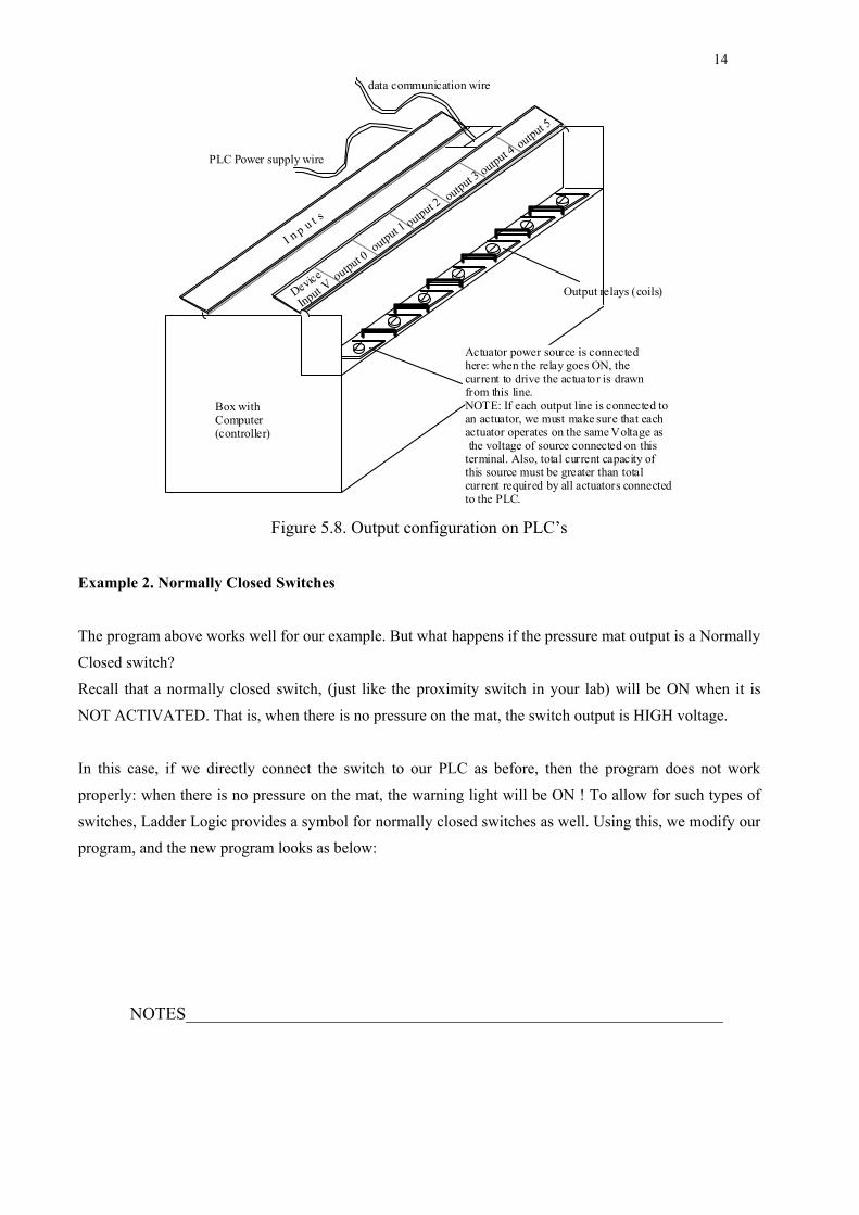
Device
Input Voutput 0
output 1 output 2output 3
output 4output 5
PLC Power supply wire
I n p u t s
Box with Computer (controller)
data communication wire
Output relays (coils)
Actuator power source is connected here: when the relay goes ON, the current to drive the actuator is drawn from this line. NOTE: If each output line is connected to an actuator, we must make sure that each actuator operates on the same Voltage as the voltage of source connected on this terminal. Also, total current capacity of this source must be greater than total current required by all actuators connected to the PLC.
Figure 5.8. Output configuration on PLC’s
Example 2. Normally Closed Switches
The program above works well for our example. But what happens if the pressure mat output is a Normally
Closed switch?
Recall that a normally closed switch, (just like the proximity switch in your lab) will be ON when it is
NOT ACTIVATED. That is, when there is no pressure on the mat, the switch output is HIGH voltage.
In this case, if we directly connect the switch to our PLC as before, then the program does not work
properly: when there is no pressure on the mat, the warning light will be ON ! To allow for such types of
switches, Ladder Logic provides a symbol for normally closed switches as well. Using this, we modify our
program, and the new program looks as below:

15
NOTES______________________________________________________________
I:0/1 O:0/1
Notice two things:
1. The physical connection of the pressure mat switch output wire is still at the same terminal on the PLC,
and so has the same name, I:0/1.
2. The symbol for the NORMALLY CLOSED (NC) switch (also called an EXAMINE IF OFF instruction)
is --|/|-- where the diagonal line going between the two vertical bars
Let’s look at how this circuit works:
Under normal conditions, when no person has stepped on the mat, the output of the pressure mat is HIGH
voltage (NC). So the terminal I:0/1 sees a high voltage, and activates the input switch I:0/1 in the ladder
program. Therefore, the right side of the Input switch is at ZERO voltage and the Output coil is OFF.
Therefore, the Warning light is OFF.
When you step on the pressure mat, the switch is activated, and so the mat output wire is at ZERO voltage.
Thus, I:0/1 sees a ZERO voltage, and since it is NC, the switch terminals are conducting. Therefore, the
Output coil O:0/1 will be subjected to HIGH voltage, and the warning light is turned ON.
Example 3. Complex Logical Conditions
The Ladder program can have more than one line. Also, the logic on each line (the “IF (conditions)” part)
can be much more complex than shown in example 1.
We want to enhance the safety of the work area. Therefore, we install two separate pressure mats around
the robot. The outer mat is the warning only area. If this mat is activated, the warning light goes ON. The
inner mat covers the area within the reach of the robot. If this mat is activated, the warning is ON, and also,
the Robot is switched off automatically. After stepping away from this mat, the person has to manually
switch the robot back ON. The figure below shows the configuration:

16
NOTES______________________________________________________________
outer pressure sensitive mat
robotto PLC Output: 1
warning bulb
Sensor output, connected to PLC Input: 1
inner pressure sensitive mat
Sensor output, connected to PLC Input: 2
to PLC Output: 2
Figure 5.9. Schematic of extended robot area example
Let us see how to construct the ladder logic program for this situation.
We now have two different actuators to control: the robot, and the light. First consider the warning light:
I:0/1 O:0/1
I:0/2
Notice how the outputs of both the pressure mats have been connected IN PARALLEL, so that if either of
the two mats is activated, the warning light will be ON. This type of a connection is called a BRANCH.
17
NOTES______________________________________________________________
Branches are used when you need to implement ‘OR’ logic in Ladder Logic Programs. Above, the logic
was: IF (I:0/1 OR I:0/2) THEN (O:0/1).
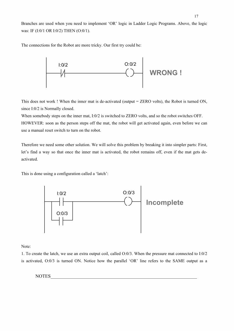
The connections for the Robot are more tricky. Our first try could be:
I:0/2 O:0/2
WRONG !
This does not work ! When the inner mat is de-activated (output = ZERO volts), the Robot is turned ON,
since I:0/2 is Normally closed.
When somebody steps on the inner mat, I:0/2 is switched to ZERO volts, and so the robot switches OFF.
HOWEVER: soon as the person steps off the mat, the robot will get activated again, even before we can
use a manual reset switch to turn on the robot.
Therefore we need some other solution. We will solve this problem by breaking it into simpler parts: First,
let’s find a way so that once the inner mat is activated, the robot remains off, even if the mat gets de-
activated.
This is done using a configuration called a ‘latch’:
IncompleteI:0/2 O:0/3
O:0/3
Note:
1. To create the latch, we use an extra output coil, called O:0/3. When the pressure mat connected to I:0/2
is activated, O:0/3 is turned ON. Notice how the parallel ‘OR’ line refers to the SAME output as a

18
NOTES______________________________________________________________
SWITCH ! Thus, when O:0/3 is turned ON, this switch is also turned ON. Now, even if I:0/2 is OFF,
O:0/3 remains ON, since it is using itself to stay ON ! This is a very common configuration, called a latch.
Now we can use this new switch O:0/3 to control the Robot:
IncompleteI:0/2 O:0/3
O:0/3
O:0/3 O:0/2
Thus, soon as the inner mat is switched, it latches O:0/3, which in turn switches the Robot OFF (from the
second line of the ladder program).
This solution is OK, except: what do we do when we want to turn the Robot back ON? Logically, we must
be able to switch O:0/3 to ZERO volts, so as to turn the robot ON. Doing this is now easy:
I:0/2 O:0/3
O:0/3
O:0/3 O:0/2
I:0/3

19
NOTES______________________________________________________________
Notice how pressing I:0/3 (which is a push-button switch to reset the Robot, connected to Input line I:0/3),
causes output coil O:0/3 to switch off (first row of program). This in turn causes the Robot to be switched
ON (row 2 of program).
We are now almost done, except for one last detail: What if one person accidentally stepped on the inner
mat, and is still standing there, but another operator press the Reset button ? This would still cause the
Robot to start -- but is not safe ! So we will ensure that the Robot only operates when the inner mat switch
is OFF. Doing this is also easy, and the final program for the entire example looks like this:
I:0/2 O:0/3
O:0/3
O:0/3 O:0/2
I:0/3
I:0/2
I:0/1 O:0/1
I:0/2Legend:
I:0/1 connected to Outer Mat Switch
I:0/2 connected to Inner Mat Switch
I:0/3 connected to Push Button for robot reset
O:0/1 connected to warning light
O:0/2 connected to robot
Switch Naming Conventions:
You may have noticed that we are using a system for giving names to the different switches and coils that
we connect wires to. All Inputs to our logic (which are usually the outputs of sensors, or manual push-
buttons) are connected on the INPUT side of the PLC. The Input terminals have specific names, to identify
which sensor is connected at which terminal. I am using the following convention. The first character
indicates the type of instruction:
‘I’ indicates an external Input terminal
‘O’ indicates and external Output terminal.

20
NOTES______________________________________________________________
The number directly after the ‘:’ indicates which “slot” of the PLC the particular switch is connected on.
For small controllers, all Inputs and Outputs are located on the same “slot”, called slot-0. On larger PLC’s,
there may be many “slots” where Input or Output terminals can be attached. Each slot has a given
identification number, which can be used to identify the switch location.
The number after the ‘/’ indicates the terminal number where the particular Input or Output wire is
connected. For each slot, the terminal numbers are fixed, and printed on the PLC. Typically, one Input or
Output slot can have between 10 to 20 terminals. If you need to control a very large factory system, with
hundreds of sensors and many actuators, you will need a large PLC with many extra ‘slots’.
In practical cases, most PLC manufacturers will allow you to give any name to your switches (and timers
and counters) – this makes it easier to debug large PLC programs.
More on Example 3: Internal Switches
As shown above, the example 3 above will work. However, we can still improve it. Notice that the Output
terminal number 3, ):0/3, is used by our program. However, that particular terminal point of the PLC is not
connected to any actuator. In effect, we are only using this Output as an “internal variable” in our program:
it is not an EXTERNAL OUTPUT. Imagine if our PLC has 6 output terminals. If we keep using External
output terminals as ‘internal variables’ in our programs, we cannot use these terminals for controlling
actuators directly. To avoid using External outputs as internal variables, all PLC’s allow you to use
INTERNAL SWITCHES. An internal switch is just the same as an output relay -- except that it is not
associated with any External terminal. In Allen-Bradley hardware, such internal switches are given names
starting with the letter ‘B’, followed by an integer.
We can therefore further improve our program as follows:

21
NOTES______________________________________________________________
I:0/2 B1
B1
B1 O:0/2
I:0/3
I:0/2
I:0/1 O:0/1
I:0/2Legend:
I:0/1 connected to Outer Mat Switch
I:0/2 connected to Inner Mat Switch
I:0/3 connected to Push Button for robot reset
O:0/1 connected to warning light
O:0/2 connected to robot
This program will work the same as the earlier one, except now the terminal O:0/3 is free to be used for
controlling another actuator.
Example 4. XOR switch
Following is a simple example of how to implement an XOR switch using Ladder Logic. Recall that A
XOR B, for two independent switches ‘A’ and ‘B’, is ON when exactly one of the switches is ON (IF (A is
ON AND B is OFF) OR (A is OFF AND B is ON). This is easily translated into a ladder logic program:
I:0/1 O:0/1
I:0/2I:0/1
I:0/2
O:0/1 = I:0/1 XOR I:0/2
Exercise: Try all combinations of values for I:0/1 and I:0/2 and check the solution.

22
NOTES______________________________________________________________
Example 5. Doing more with PLC’s: Timers
Another thing we’d like to do is time delays, and timed control of equipment. This is very useful for many
control situations. Common examples of automatic controls with time delays include door lock switches
(like the number lock for the Industrial Automation Lab door), Elevator doors (which close after a fixed
period of staying open) etc.
Let’s write a ladder logic program to control a card operated door lock. The lock is disengaged (unlocked)
by switching ON a solenoid. The solenoid is activated using two switches: (a) from outside the room door,
the signal to activate the solenoid comes from the Number-Pad, if the correct sequence of code numbers is
pressed; (b) From inside the room door, there is just a simple push button, which can be used to disengage
the lock. Upon activation, the door stays unlocked for 5 seconds, and then locks again.
There are two components in the ladder logic program for this example: First, when a ‘open door’ signal is
received, it must be latched (so that the door stays unlocked even if the push button is released). Second, a
timer instruction in the ladder logic is used to release the latch after the specified time (5 seconds). A
typical timer instruction, as used below, is called TIMER ON DELAY.
The ladder logic program is shown below:
Legend:
I:0/1 Number Pad Signal to open door
I:0/2 Push Button signal to open door
O:0/1 Solenoid to unlock door
O:0/1
T4: 1I:0/1 O:0/1
I:0/2DN
O:0/1
Preset:Accum:
Base:
ENTimer: T4: 1
0.01500
0
DN

23
NOTES______________________________________________________________
Notes:
Row 1. If either the number pad unit, or the push button activate the door open signal, then output O:0/1 is
turned ON. Also, the left side switch O:0/1 latches to this output, so even if the push button is released,
O:0/1 will stay ON.
Row 2. This is the row with the timer instruction. To program the timer, four things must be input:
• Name of the timer (in the example, T4: 1). Every timer in a program must have a unique name. For Allen
Bradley programs, all timers must have a name given by T4: [number], where [number] can be any non-
negative integer, such as 0, 1, 2, 3, 4....
• Time Base: (in the example, 0.01 sec). This shows the time duration after which the timer updates the
accumulated delay value.
• Preset: This is the number of time base increments after which the timer will switch ON. In our case, we
need a delay of 5 secs, so it’s value is 5/(time base) = 5/0.01 = 500 steps.
• Accumulated: This is the number of time increments that have currently elapsed. When the accumulated
value equals or exceeds the Preset value, a switch called the T4: 1 / DN switch turns ON. Notice the name
of the switch is the same as the Timer, with extension /DN (which is a short form for DONE).
The timer will keep counting up time when the left side (IF (conditions) of the timer row are ON. In our
example, when O:0/1 is ON, the timer starts counting, in steps of 1.0 sec (since base = 1.0 sec) time. After
5.0 seconds, Preset is equal to Accumulated value, and the T4: 1/ DN switch turns ON.
This causes the Output O:0/1 to turn OFF ( from row 1), and the door locks again.
Example 6: More on Timers
Let us now extend the timer example with two more features.
(a) When the door is unlocked, we would also like to have an indicator light to turn ON, to give us a visual
input.
(b) While the door is unlocked, if someone again activates the push button, then the door should stay
unlocked for 5 seconds starting from the new activation time of the push button.
The solution to these extensions is quite simple. For case (a), we notice that the switch O:0/1 is ON if and
only if the door is unlocked. Therefore, we can use this to turn on a light also.

24
NOTES______________________________________________________________
The second requirement uses another feature of the TIMER instruction on Ladder Logic Programs: this is
called the Timer RESET. When a particular timer switch is reset, it’s Accumulated value is set to ZERO.
Therefore, using a timer T4: 1 RESET will do what we want. Of course, we would like to use I:0/2 to reset
our timer (why ?).
The final solution is as follows:
Legend:
I:0/1 Number Pad Signal to open door
I:0/2 Push Button signal to open door
O:0/1 Solenoid to unlock door
O:0/1
T4: 1I:0/1 O:0/1
I:0/2DN
O:0/1
Preset:Accum:
Base:
ENTimer: T4: 1
0.01500
0
DN
O:0/1 O:0/2
T4: 1I:0/2RESET
O:0/2 ‘Door Unlocked’ Light Indicato
In the example, please note that the first two rows are exactly the same as for example 5. The third row
makes the indicator light to go ON when the door is unlocked. The final row shows the logic to reset the
timer. Note how the TIMER RESET instruction is programmed.

25
NOTES______________________________________________________________
Example 7. Counters
Finally, we introduce another useful feature of PLC’s, namely, COUNTERS. A counter is a device which
can be used to count the number times an EVENT happens. The word ‘EVENT’ in this definition
commonly means the following: if input switch turns ON from an OFF state that is, if it was OFF, and then
turned ON, then the event has happened one time. Thus if a switch goes: OFF -> ON -> OFF -> ON, then
exactly two event are said to have occurred. In other words, the counter counts the number of times the IF
(conditions) part of the instruction goes from false (OFF) to true (ON).
First, let us consider a simple example. In a factory, parts arrive at a workstation, one by one, on a
conveyor. A photoswitch is used to detect arriving parts. After 4 parts have arrived, the conveyor is
stopped and a light indicator switches ON. The operator then loads the arrived parts into the machine tool,
and restarts the conveyor for the next batch of parts to arrive. The following ladder program can be used to
provide the control for this problem.
Legend:
I:0/1 Photo switch
I:0/2 Operator controlled Push Button to restart conveyor
O:0/1 Conveyor belt
O:0/2 Light Indicator
I:0/0 Conveyor ON
I:0/1
CU
DN
C5:1 O:0/2
C5: 1I:0/2
RESET
Preset:Accum:
Count Up
C5: 1
40
Counter:
DN
O:0/1O:0/2I:0/0
Notice how the COUNTER is programmed. The COUNTER INSTRUCTION requires you to specify the
following things:

26
NOTES______________________________________________________________
1. Whether the counter will count UP (that is, 1..2..3..4...etc.) or DOWN (as in 4..3..2..1..0).
2. The unique name of the counter. In case of Allen Bradley PLC’s, the names assigned to counters are in
the following format: C5: <number>, where <number> is a non-negative integer.
3. The preset value, which is usually the number of EVENTS after which you need the counter to give you
a signal (output).
4. The current accumulated value. Each time the counter IF (conditions) goes from false to true, the
accumulated value is increased by 1. In our example, each time the switch I:0/1 goes ON, the counter
accumulated value increases.
Once the accumulated value is equal to or larger than the preset value, a switch is turned ON: this is the
COUNTER DONE switch; in our example, this is the C5: 1/DN switch.
Also note that the DONE switch is turned OFF when the counter is RESET (as by row 4 of the program).
Example 8. Car Wash
In an automatic car wash, when a car drives into the wash-area, a limit switch turns the washer on. The
washing is in tree subsequent phases: First, soapy water is sprayed on the car for 30 secs; Next, the car is
rinsed with a spray from the clean water pipes; Finally, automatic scrubber brushes dry the car for 15 secs.
After washing 50 cars, the scrubber brushes are changed automatically. The entire operation is controlled
using a PLC. A ladder logic that can be used to control this activity is as follows:

27
NOTES______________________________________________________________
I:0/1 I:0/2 B1
O:0/0B1 T4:0 T4:1 T4:2
O:0/1B1
O:0/2B1
O:0/3
B1
B1
B1
I:0/1 : System On I:0/2 : Emergency Stop I:0/3 : Limit Switch
O:0/0 : Soap Water On O:0/1 : Rinse On O:0/2 : Scrubber On O:0/3 : Activate Scrubber Change
Notice how B1 and the timer outputs are used to control the logic according to the required timing.
O:0/2
Preset:Accum:
T4: 1
60000
Base: 0.01
Preset:Accum:
T4: 2
75000
Base: 0.01
Preset:Accum:
T4: 0
30000
Base: 0.01
DNT4:0
DNT4:0
DN
DNT4:1
DNT4:1
DN
DNT4:2
DNT4:2
DN
Preset:Accum:
C5: 0
500
CTU
I:0/3 T4:0RES
I:0/3 T4:1RES
I:0/3 T4:2RES
O:0/3 C5:0RES
C5: 0
DN
EN
EN
EN
EN

28
NOTES______________________________________________________________
Programming a PLC
Now we know how to write Ladder Logic programs to control automation devices. We also know how to
connect the external Inputs and Outputs (I/O’s) to the sensors and actuators. But how do we input our
ladder logic program into the PLC computer ? There are two ways to do so:
Hand Held Console: this is a special device which can be connected to a PLC. It has special buttons on a
small keyboard, which represent different types of ladder logic instructions. It allows you to enter a ladder
logic program, instruction by instruction, and row by row, straightaway into the PLC. It also has special
buttons on its keyboard to execute your ladder logic program, once the program has been stored inside the
PLC.
PC interface program: The other, and better way to enter the ladder logic program into the PLC is to first
use a software program to write the ladder logic program on a Computer (PC). Once the program has been
written, and tested (debugged), it can be used on the PLC. Of course, to write a ladder logic program in a
PC, we need to use special software. In our case, we use a special program, called ‘APS’ (which stands for
‘Advanced Programming System’) to write ladder logic programs in the PC. This program is specialized to
be used for Allen Bradley PLC’s (which you use in your lab). In industry, you may work with PLC’s
manufactured by other companies -- in that case, the other company will provide you with a different
software program to write your ladder logic programs. In fact, even the instruction specifications for
different types of PLC’s may differ a little; however, the basic ideas used by any ladder logic programming
language are always the same: they are all based on Relay logic circuits, and all provide you with counters
and timers.
Now that we understand how to write ladder logic programs to control I/O based discrete event situations
in automation, lets get some more understanding of what is really happening inside a PLC when it executes
the ladder logic program.
The architecture and functioning of the PLC
The figure below shows a view of the architecture as well as functioning of a simple PLC. As indicated,
the PLC is organized internally into three basic parts.

29
NOTES______________________________________________________________
The first part is the data tables. The data tables are divided into two parts: the input table, and the output
table. Each table has a column of names of each of the input/output switches used in the ladder logic
program that is to be executed. The names are associated with the memory location where the value of the
state of the switch is stored (the registers).
The second part is the user program. The program is stored in a separate area of the PLC memory, and
the ladder logic evaluation at each step is performed by consulting the program.
The third part of the PLC is the processor itself. The processor looks at the value of each of the inputs,
executes the user program, and then updates the value of the output coils according as the results dictate.
One cycle of these evaluations and updates is called an operating cycle. Thus the operating cycle is
composed of the phases: Input scan, Program scan, Processing cycle, and Output scan.
Phase 1Phase 2
Phase 3
Program Memory
Processor
Accumulator
output register
output
30
37
30
31
32
33
34
35
36
37
input input register
00
01
02
03
04
05
06
07
08
09
10
11
00
11
Figure 5.10. Operation cycle in a PLC
Although PLC's were extremely popular and industrially successful as intelligent controlling devices in
industry, their use is now on the decline. Some of the reasons for this change include:

30
NOTES______________________________________________________________
• Modern microprocessors are becoming more and more powerful/cheap
• Increasing computer literacy of shop-floor personnel
• New demands from controlling devices including data processing, sophisticated logic control etc.
The study of PLC's however, is essential for two reasons: Firstly, the architecture of the PLC is
surprisingly close to the structure of simple microprocessors, which are the brains of any computer.
Secondly, PLC's are still ubiquitous on the shop-floors of countless industries, and quite successfully being
used to control processes. The hardware is cheap; the software (ladder logic) is easy to learn so factory
personnel can learn it quickly and inexpensively. Therefore a qualified engineer should be familiar with
their structure, functioning and programming.