Embed Size (px)
Citation preview
ii
NOTE A l l in format ion in th is manual is based on the la test product in format ion ava i lab le a t the t ime of pr in t ing. H i tach i has rev iewed the accuracy of th is manual , but assumes no respons ib i l i ty for any omiss ions or er rors which may appear . The des ign of the product is under constant rev iew and, whi le every e f for t is made to keep th is manual up to date, the r ight is reserved to change spec i f icat ions and equipment a t any t ime wi thout pr ior not ice.
PROHIBITION These products should not be used for medical , power supply, nuc lear , water supply, dra inage p lants , t ra f f ic cont ro l , mi l i ta ry, space, nor d isaster prevent ion equipment . D ivers ion and/or resa le o f these products wi thout th is manual is proh ib i ted. Reproduct ion of the contents o f th is manual in whole or in par t , wi thout wr i t ten permiss ion of H i tach i , is proh ib i ted.
TRADEMARKS HITACHI-S10/2α, S10/4α and PSEα are registered trademarks of Hitachi, Ltd.
BI-NR-HS<IC-IC> (FL-MW20)
FIRST EDITION, FEBRUARY, 1999, SAE - 3 - 131 (B) (out of print) SECOND EDITION, DECEMBER, 2000, SAE - 3 - 131 (D) (out of print)
THIRD EDITION, OCTOBER, 2001, SAE - 3 - 131 (E) (out of print) FOURTH EDITION, SEPTEMBER, 2003, SAE - 3 - 131 (F) (out of print)
FIFTH EDITION, DECEMBER, 2004, SAE - 3 - 131 (G) All Rights Reserved, Copyright © 1999, 2004, Hitachi, Ltd.

iii
H i tach i , L td . , warrants i ts products to be manufactured in accordance wi th publ ished spec i f ica t ions and f ree f rom defects in mater ia ls and/or workmanship . H i tach i , L td . , warrants i ts products against defects in par ts and workmanship for one fu l l year f rom date o f purchase. HITACHI, LTD. , MAKES NO WARRANTIES, EITHER EXPRESS OR IMPLIED EXCEPT AS PROVIDED HEREIN, INCLUDING WITHOUT LIMITATION THEREOF, WARRANTIES AS TO MARKETABILITY FOR A PARTICULAR PURPOSE OF USE, OR AGAINST INFRINGEMENT OF ANY PATENT. IN NO EVENT SHALL HITACHI BE LIABLE FOR ANY DIRECT, INCIDENTAL OR CONSEQUENTIAL DAMAGES OF ANY NATURE, OR COSTS, CHARGES, LOSSES OR EXPENSES RESULTING FROM ANY DEFECTIVE PRODUCT OR THE USE OF ANY PRODUCT.
LIMITED WARRANTY
SOFTWARE UP–TO DATE POLICY Hitachi, Ltd., constantly reviews its software so as to incorporate the latest technology. Hitachi reservesthe right to make changes to any software to improve reliability, function, or design. Hitachi cannot beheld responsible for any errors in its software.

iv
SAFETY PRECAUTIONS
Read this manual thoroughly and follow all the safety precautions and instructions given in this manual before operations such as system configuration and program creation. Keep this manual handy so that you can refer to it any time you want. If you have any question concerning any part of this manual, contact your nearest Hitachi branch office or service engineer. Hitachi will not be responsible for any accident or failure resulting from your operation in any manner not described in this manual. Hitachi will not be responsible for any accident or failure resulting from modification of software provided by Hitachi. Hitachi will not be responsible for reliability of software not provided by Hitachi. Make it a rule to back up every file. Any trouble on the file unit, power failure during file access or incorrect operation may destroy some of the files you have stored. To prevent data destruction and loss, make file backup a routine task. Furnish protective circuits externally and make a system design in a way that ensures safety in system operations and provides adequate safeguards to prevent personal injury and death and serious property damage even if the product should become faulty or malfunction or if an employed program is defective. If an emergency stop circuit, interlock circuit, or similar circuit is to be formulated, it must be positioned external to the programmable controller. If you do not observe this precaution, equipment damage or accident may occur when the programmable controller becomes defective. Before changing the program, generating a forced output, or performing the RUN, STOP, or like procedure during an operation, thoroughly verify the safety because the use of an incorrect procedure may cause equipment damage or other accident.
“RUN/STOP” SWITCH CAUTION
The “RUN/STOP” switch only stops execution of the ladder logic program or HI-FLOW program. Digital and analog outputs are left in the active state when execution stops, unless the optional rungs described in the CPU manual have been added. The “RUN/STOP” switch does not affect the operation of C-language or FA-BASIC language programs. Outputs can still be produced in response to C-language or FA-BASIC programs, or by the action of programmers typing in commands in these languages, while the “RUN/STOP” switch is in the “STOP” position. DO NOT DEPEND ON THE STOP SWITCH TO STOP MOVING PARTS OR TO PREVENT UNEXPECTED MOTION OR ENERGIZATION. USE HARDWIRED SAFETY DISCONNECT AND LOCK OUT POWER AND CONTROL VOLTAGES BEFORE WORKING ON ELECTRICAL CIRCUITS OR PARTS THAT CAN MOVE.
v
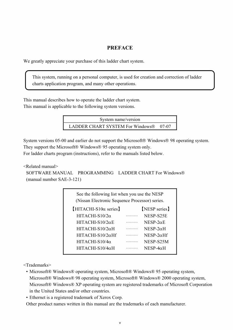
PREFACE We greatly appreciate your purchase of this ladder chart system.
This manual describes how to operate the ladder chart system. This manual is applicable to the following system versions.
System name/version LADDER CHART SYSTEM For Windows 07-07
System versions 05-00 and earlier do not support the Microsoft Windows 98 operating system. They support the Microsoft Windows 95 operating system only. For ladder charts program (instructions), refer to the manuals listed below. <Related manual>
SOFTWARE MANUAL PROGRAMMING LADDER CHART For Windows (manual number SAE-3-121)
See the following list when you use the NESP (Nissan Electronic Sequence Processor) series.
【HITACHI-S10α series】 【NESP series】 HITACHI-S10/2α HITACHI-S10/2αE HITACHI-S10/2αH HITACHI-S10/2αHf HITACHI-S10/4α HITACHI-S10/4αH
………
………
………
………
………
………
NESP-S25E NESP-2αE NESP-2αH NESP-2αHf NESP-S25M NESP-4αH
<Trademarks>
• Microsoft® Windows® operating system, Microsoft® Windows® 95 operating system, Microsoft® Windows® 98 operating system, Microsoft® Windows® 2000 operating system, Microsoft® Windows® XP operating system are registered trademarks of Microsoft Corporation in the United States and/or other countries.
• Ethernet is a registered trademark of Xerox Corp. Other product names written in this manual are the trademarks of each manufacturer.
This system, running on a personal computer, is used for creation and correction of ladder charts application program, and many other operations.

vi
Systems Supported by Windows® 2000 and Windows® XP The systems supported by Microsoft® Windows® 2000 operating system (hereafter abbreviated as Windows® 2000) and Microsoft® Windows® XP operating system (hereafter abbreviated as Windows® XP) are shown in the following table. Systems of earlier versions than those shown in the following table are not supported by Windows® 2000 and Windows® XP but supported by only Microsoft® Windows® 95 operating system (hereafter abbreviated as Windows® 95) and Microsoft® Windows® 98 operating system (hereafter abbreviated as Windows® 98). (The system names in the following table are hereafter abbreviated as each system.) <Table of Systems Supported by Windows® 2000 and Windows® XP>
No. System name Type Version Windows® 2000 Windows® XP1 S10Tools SYSTEM S-7890-01 07-05 √ √ 2 LADDER CHART SYSTEM S-7890-02 07-05 √ √ 3 HI-FLOW SYSTEM S-7890-03 07-02 √ √ 4 CPMS LOADING SYSTEM S-7890-04 07-04 √ √ 5 CPMSE LOADING SYSTEM S-7890-05 07-04 √ √ 6 CPMS DEBUGGER SYSTEM S-7890-06 07-02 √ √ 7 CPMSE DEBUGGER SYSTEM S-7890-07 07-02 √ √ 8 GP-IB LOADING SYSTEM S-7890-08 07-01 √ √ 9 BACKUP RESTORE SYSTEM S-7890-09 08-01 √ √
10 RPDP/S10 SYSTEM S-7891-10 03-03 √ (*2) ns (*1) 11 NX/Tools-S10 SYSTEM S-7890-13 07-02 √ √ 12 4α LADDER CHART SYSTEM S-7890-17 07-05 √ √ 13 4αH LADDER CHART SYSTEM S-7890-18 07-05 √ √ 14 LADDER COMMENT CONVERTER SYS S-7890-19 06-01 √ √ 15 HIGH SPEED REMOTE I/O SYSTEM S-7890-21 07-01 √ √ 16 CPU LINK SYSTEM S-7890-22 07-01 √ √ 17 4ch ANALOG PULSE COUNTER SYS S-7890-23 07-01 √ √ 18 EXTERNAL SERIAL LINK SYSTEM S-7890-24 07-02 √ √ 19 S10ET LINK SYSTEM S-7890-25 07-02 √ √ 20 J.NET SYSTEM S-7890-27 07-02 √ √ 21 OD.RING/SD.LINK SYSTEM S-7890-28 07-03 √ √ 22 ET.NET SYSTEM S-7890-29 07-01 √ √ 23 FL.NET SYSTEM S-7890-30 07-03 √ √ 24 D.NET SYSTEM S-7890-31 07-04 √ √ 25 LADDER CHART MONITOR SYSTEM S-7890-34 07-04 √ √ 26 HI-FLOW MONITOR SYSTEM S-7890-35 07-01 √ √ 27 IR.LINK SYSTEM S-7890-36 07-02 √ √ 28 Crossing C compiler
(manufactured by Mentor Graphics Corporation)
MCP68K 5.3 √ (*2) ns (*1)
√: Supported ns: Not supported (*1) Crossing C compiler (No.28) is not supported by Windows® XP. Use it on Windows® 2000. (*2) Crossing C compiler (No.28) must be a version supported by Windows® 2000 (later than version 5.3) as
a premise.

vii
<Definitions of Terms> N coil: A ladder program converted into a form that can be run on the PCs by pasting a symbol on
the sheet displayed on a PC. Process: A HI-FLOW program converted into a form that can be run on the PCs by pasting a
symbol on the sheet displayed on a PC. Compile: To convert an application program such as a ladder chart and HI-FLOW into a form (N
coil, process, etc.) that can be run on the PCs. Build: To compile only a corrected application program. Rebuild: To compile every existing application program. Sheet: Paper to prepare an application program of ladder chart and HI-FLOW, etc. This paper is
controlled on a PC. PCs: An abbreviation of Programmable Controllers.
This is a general term for PLC such as the S10α and S10mini series. PLC: An abbreviation of Programmable Logic Controller.
This is an industrial electronic device to exert sequence control, having an incorporated program. The S10α and S10mini series come under this PLC.
<Note for storage capacity calculations> Memory capacities and requirements, file sizes and storage requirements, etc. must be calculated according to the formula 2n. The following examples show the results of such calculations by 2n (to the right of the equals signs). 1 KB (kilobyte) = 1024 bytes 1 MB (megabyte) = 1,048,576 bytes 1 GB (gigabyte) = 1,073,741,824 bytes As for disk capacities, they must be calculated using the formula 10n. Listed below are the results of calculating the above example capacities using 10n in place of 2n. 1 KB (kilobyte) = 1000 bytes 1 MB (megabyte) = 10002 bytes 1 GB (gigabyte) = 10003 bytes
viii
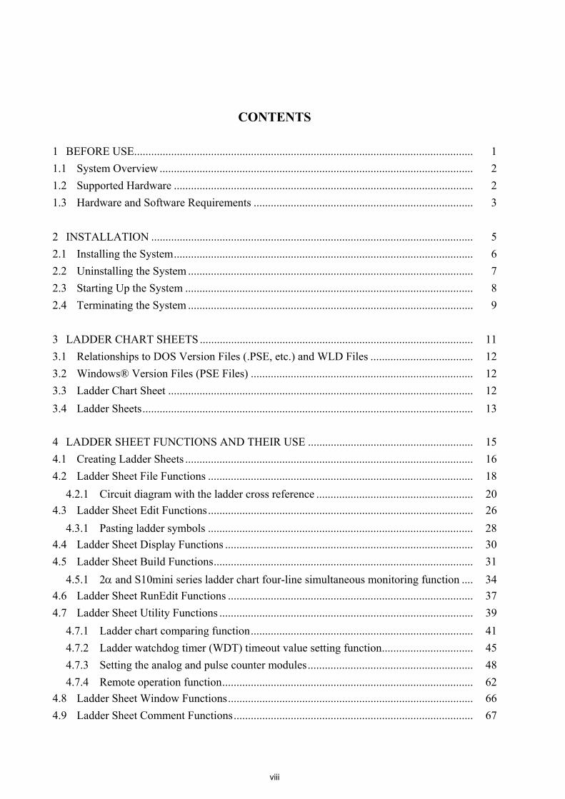
CONTENTS
1 BEFORE USE....................................................................................................................... 1 1.1 System Overview .............................................................................................................. 2 1.2 Supported Hardware ......................................................................................................... 2 1.3 Hardware and Software Requirements ............................................................................. 3 2 INSTALLATION ................................................................................................................. 5 2.1 Installing the System......................................................................................................... 6 2.2 Uninstalling the System .................................................................................................... 7 2.3 Starting Up the System ..................................................................................................... 8 2.4 Terminating the System .................................................................................................... 9 3 LADDER CHART SHEETS ................................................................................................ 11 3.1 Relationships to DOS Version Files (.PSE, etc.) and WLD Files .................................... 12 3.2 Windows® Version Files (PSE Files) .............................................................................. 12 3.3 Ladder Chart Sheet ........................................................................................................... 12 3.4 Ladder Sheets.................................................................................................................... 13 4 LADDER SHEET FUNCTIONS AND THEIR USE .......................................................... 15 4.1 Creating Ladder Sheets ..................................................................................................... 16 4.2 Ladder Sheet File Functions ............................................................................................. 18
4.2.1 Circuit diagram with the ladder cross reference ....................................................... 20 4.3 Ladder Sheet Edit Functions............................................................................................. 26
4.3.1 Pasting ladder symbols ............................................................................................. 28 4.4 Ladder Sheet Display Functions ....................................................................................... 30 4.5 Ladder Sheet Build Functions........................................................................................... 31
4.5.1 2α and S10mini series ladder chart four-line simultaneous monitoring function .... 34 4.6 Ladder Sheet RunEdit Functions ...................................................................................... 37 4.7 Ladder Sheet Utility Functions ......................................................................................... 39
4.7.1 Ladder chart comparing function.............................................................................. 41 4.7.2 Ladder watchdog timer (WDT) timeout value setting function................................ 45 4.7.3 Setting the analog and pulse counter modules.......................................................... 48 4.7.4 Remote operation function........................................................................................ 62
4.8 Ladder Sheet Window Functions...................................................................................... 66 4.9 Ladder Sheet Comment Functions.................................................................................... 67
1 BEFORE USE
1 BEFORE USE
- 2 -
This manual is intended for users who want to program a personal computer under the Windows®. 1.1 System Overview
Ladder chart For Windows® (hereinafter referred to as the ladder chart system) is used to create, correct, monitor, and debug ladder charts application program for the series and S10α series. The ladder chart system can be operated in the same way as ordinary Windows® applications are operated.
1.2 Supported Hardware
The ladder chart system supports PCs of the following three series. 2α series 4α series S10mini series
This manual covers PCs of these three series. All example screens in this manual are those actually used in the ladder chart system for the 2α and S10mini series, and some of them may differ slightly from the corresponding screens for the 4α series. Some functions supported by the 2α series are not supported by the 4α series. (See “4 LADDER SHEET FUNCTIONS AND THEIR USE.”) The Remote Operation function of the Utility function is only available for the S10mini series. It is not available for the S10/2α and S10/4α series.
1 BEFORE USE
- 3 -
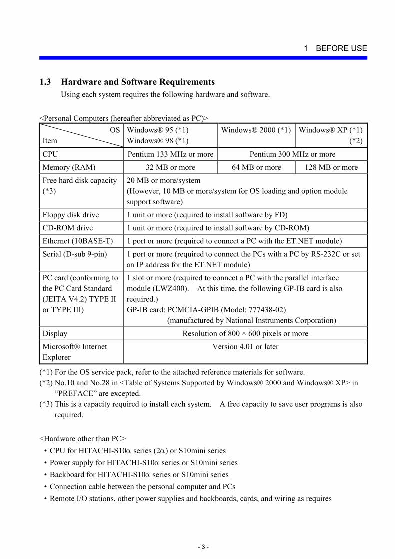
1.3 Hardware and Software Requirements Using each system requires the following hardware and software.
<Personal Computers (hereafter abbreviated as PC)>
OSItem
Windows® 95 (*1) Windows® 98 (*1)
Windows® 2000 (*1) Windows® XP (*1)(*2)
CPU Pentium 133 MHz or more Pentium 300 MHz or more
Memory (RAM) 32 MB or more 64 MB or more 128 MB or more Free hard disk capacity (*3)
20 MB or more/system (However, 10 MB or more/system for OS loading and option module support software)
Floppy disk drive 1 unit or more (required to install software by FD) CD-ROM drive 1 unit or more (required to install software by CD-ROM)
Ethernet (10BASE-T) 1 port or more (required to connect a PC with the ET.NET module) Serial (D-sub 9-pin) 1 port or more (required to connect the PCs with a PC by RS-232C or set
an IP address for the ET.NET module) PC card (conforming to the PC Card Standard (JEITA V4.2) TYPE II or TYPE III)
1 slot or more (required to connect a PC with the parallel interface module (LWZ400). At this time, the following GP-IB card is also required.) GP-IB card: PCMCIA-GPIB (Model: 777438-02)
(manufactured by National Instruments Corporation)
Display Resolution of 800 × 600 pixels or more Microsoft® Internet Explorer
Version 4.01 or later
(*1) For the OS service pack, refer to the attached reference materials for software. (*2) No.10 and No.28 in <Table of Systems Supported by Windows® 2000 and Windows® XP> in
“PREFACE” are excepted. (*3) This is a capacity required to install each system. A free capacity to save user programs is also
required. <Hardware other than PC>
• CPU for HITACHI-S10α series (2α) or S10mini series • Power supply for HITACHI-S10α series or S10mini series • Backboard for HITACHI-S10α series or S10mini series • Connection cable between the personal computer and PCs • Remote I/O stations, other power supplies and backboards, cards, and wiring as requires

1 BEFORE USE
- 4 -
NOTICE
Users of this product require knowledge of Windows® environments and user interfaces. The ladder chart system conforms to the Windows® standard. This manual is intended for users who have mastered the basic usage for Windows®.
CAUTION
This product can be used to rewrite programs or the content of internal registers while the PCs are running. However, if they are rewritten without sufficient care, a serious accident such as damage to a facility may occur. Check the condition of the facility before rewriting programs or the content of internal registers. When you use a personal computer with the suspend function, disable the function. The personal computer may malfunction if the suspend function remains enabled during execution of the ladder chart system. If RAM runs short during execution of an application program, an application error may result. When this happens, check the free memory capacity and, if the RAM needs to be extended, do it.

2 INSTALLATION
2 INSTALLATION
- 6 -
2.1 Installing the System (*) First, check if your CD is correct. To install each system, double-click the Setup.exe file saved in the DISK1 folder of the system CD. After installing it, an installed program window is not displayed. To install each system, install Microsoft® Internet Explorer 4.01 or later. If it is not installed, install each system after installing it.
NOTE
To operate each system, install Microsoft® Internet Explorer 4.01 or later. If it is not installed, each system does not operate normally. Before installing each system, be sure to terminate such a program residing in the memory as virus monitoring software. If each system is installed without terminating the program, an error may occur. In this case, uninstall the system by referring to “2.2 Uninstalling the System” and terminate all Windows® programs. Then, install each system once again. To install and uninstall each system by using Windows® 2000, set “Administrator” or “Member of Administrators” as the user account to be logged on. To install and uninstall each system by using Windows® XP, set “Computer administrator” as the user account to be logged on. If “Account with limitations” is set, each system does not operate normally.
(*) No.10 and No.28 in <Table of Systems Supported by Windows® 2000 and Windows® XP>
in “PREFACE” are excepted.

2 INSTALLATION
- 7 -
2.2 Uninstalling the System (*) To uninstall each system for version-up, observe the following procedure.
(1) Uninstalling from Windows® 95 or Windows® 98
Open [Settings] in the [Start] menu – [Control Panel]. Double-click [Add/Remove Programs], select “Each System” by the [Install/Uninstall] tab, and click the Change/Remove button. When the [Confirm File Deletion] window is displayed, click the Yes button.
(2) Uninstalling from Windows® 2000
Open [Settings] in the [Start] menu – [Control Panel]. Double-click [Add/Remove Programs], click [Change or Remove Programs], select “Each System,” and click the Change/Remove button. When the [Confirm File Deletion] window is displayed, click the Yes button.
(3) Uninstalling from Windows® XP
Open ([Settings] – ) [Control Panel] in the [Start] menu. Double-click [Add or Remove Programs], click [Change or Remove Programs], select “Each System,” and click the Change/Remove button. When the [Confirm File Deletion] window is displayed, click the Yes button. When a shortcut of each system executable file has been created on the desktop, etc. delete this shortcut.
NOTE
When the [Remove Shared File?] window is displayed while each system is uninstalled on Windows®, click No not to delete the shared file. To install and uninstall each system by using Windows® 2000, set “Administrator” or “Member of Administrators” as the user account to be logged on. To install and uninstall each system by using Windows® XP, set “Computer administrator” as the user account to be logged on. If the [Add/Remove Programs] window is locked (inoperable) when each system is uninstalled by using Windows® 2000, log off from [Shut Down] in the [Start] menu of Windows®, and then log on again on the [Log On to Windows] window.
(*) No.10 and No.28 in <Table of Systems Supported by Windows® 2000 and Windows® XP>
in “PREFACE” are excepted.

2 INSTALLATION
- 8 -
2.3 Starting Up the System (*) (1) The system to be installed by each system is automatically registered in the [Start] menu of
Windows®. From this [Start] menu, select [Programs (All Programs)] – [Hitachi S10] – “Each System” to start the system. If the logged-on user name in installing each system is different from the user name in starting each system, each system is not displayed in the [Start] menu. In this case, create a shortcut of the executable file (extension .exe) for each system shown below and then double-click this shortcut to start each system.
<Executable File Storage Directory Table> No. System name Type Executable file storage directory (*1) Executable file name
S10Ladder.exe 1 S10Tools SYSTEM S-7890-01 C:\Hitachi\S10 S10Tool.exe
2 LADDER CHART SYSTEM S-7890-02 C:\Hitachi\S10\2ALDC S10Ladder.exe 3 HI-FLOW SYSTEM S-7890-03 C:\Hitachi\S10\HF S10Tool.exe 4 CPMS LOADING SYSTEM S-7890-04 C:\Hitachi\S10\CPMS Cpms.exe 5 CPMSE LOADING SYSTEM S-7890-05 C:\Hitachi\S10\CPMSE Cpmse.exe 6 CPMS DEBUGGER SYSTEM S-7890-06 C:\Hitachi\S10\DEBUG Debugger.exe 7 CPMSE DEBUGGER SYSTEM S-7890-07 C:\Hitachi\S10\DEBUGE DebuggerE.exe 8 GP-IB LOADING SYSTEM S-7890-08 C:\Hitachi\S10\GPIB Gpib.exe 9 BACKUP RESTORE SYSTEM S-7890-09 C:\Hitachi\S10\BACKUP SysAllSaveLoad.exe
10 NX/Tools-S10 SYSTEM S-7890-13 C:\Hitachi\S10\NX NXTool.exe 11 4α LADDER CHART SYSTEM S-7890-17 C:\Hitachi\S10\4ALDC S10Ladder_4A.exe 12 4αH LADDER CHART SYSTEM S-7890-18 C:\Hitachi\S10\4AHLDC S10Ladder_4AH.exe13 LADDER COMMENT CONVERTER SYS S-7890-19 C:\Hitachi\S10\CFCONV Cfconv.exe 14 HIGH SPEED REMOTE I/O SYSTEM S-7890-21 C:\Hitachi\S10\HISRIO HiSpeedRIO.exe 15 CPU LINK SYSTEM S-7890-22 C:\Hitachi\S10\CPULINK CpuLink.exe 16 4ch ANALOG PULSE COUNTER SYS S-7890-23 C:\Hitachi\S10\ANALOG AnalogPuls.exe 17 EXTERNAL SERIAL LINK SYSTEM S-7890-24 C:\Hitachi\S10\EXLINK ExLink.exe 18 S10ET LINK SYSTEM S-7890-25 C:\Hitachi\S10\ETLINK EtherNet.exe 19 J.NET SYSTEM S-7890-27 C:\Hitachi\S10\JNET JNet.exe 20 OD.RING/SD.LINK SYSTEM S-7890-28 C:\Hitachi\S10\ODRING-SDLINK ODRing.exe 21 ET.NET SYSTEM S-7890-29 C:\Hitachi\S10\ETNET Et_Net.exe 22 FL.NET SYSTEM S-7890-30 C:\Hitachi\S10\FLNET FLnet.exe 23 D.NET SYSTEM S-7890-31 C:\Hitachi\S10\DNET DNet.exe 24 LADDER CHART MONITOR SYSTEM S-7890-34 C:\Hitachi\S10\2ALDCM S10LadderM.exe 25 HI-FLOW MONITOR SYSTEM S-7890-35 C:\Hitachi\S10\HFM S10ToolM.exe 26 IR.LINK SYSTEM S-7890-36 C:\Hitachi\S10\IRLINK IrLink.exe
(*1) Directory name when “C” is the drive name of installing destination.
(*) No.10 and No.28 in <Table of Systems Supported by Windows® 2000 and Windows® XP> in “PREFACE” are excepted.

2 INSTALLATION
- 9 -
2.4 Terminating the System To terminate the ladder chart system, select the [Application termination] from the [File] menu. When the system terminates, the Windows® screen is displayed again.

3 LADDER CHART SHEETS
3 LADDER CHART SHEETS
- 12 -
Application programs in the ladder chart system have a structure different from that of their DOS versions. Programs on the PCs are handled in the same way as in both the ladder chart system and DOS system. In the ladder chart system, however, application programs are handled as sheets on a personal computer. 3.1 Relationships to DOS Version Files (.PSE, etc.) and WLD Files
DOS version ladder files are handled as separate files with their extensions variously determined according to the functionality. Ladder chart is capable of loading DOS version files. It can also load WLD files for ladder chart versions 5.0 and earlier.
3.2 Windows Version Files (PSE Files)
The Windows version of ladder chart saves files having the same extension (.pse) as those for the DOS version. The user can change the target for such file save operations. • Sequence (management area, SQET, TUC setting, ladder program, and user
mathematical/logical function) • Sequence + data (sequence + DW register) • Sequence + fence (sequence + DW register + ladder program free space) • Sequence + work (sequence + DW register + ladder program free space + FW/BI register) • All areas (sequence + DW register + ladder program free space + FW/BI register + registers
enumerated below) (Registers saved when all areas are selected: X, Y, J, Q, G, R, M, K, T, U, C, N, P, V, E, Z, and S, of which T, U, and C are contacts.)
To save any type of file not listed above, use the FD feature of the ladder diagram system for Windows®.
3.3 Ladder Chart Sheet
The ladder chart system manages the following type of sheet. • Ladder sheet This type is specified when creating a new sheet or opening an existing sheet.
3 LADDER CHART SHEETS
- 13 -
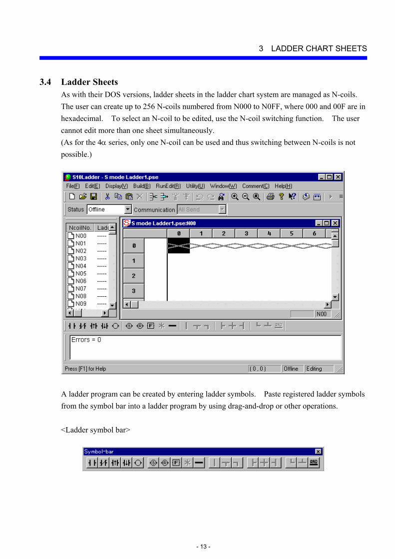
3.4 Ladder Sheets As with their DOS versions, ladder sheets in the ladder chart system are managed as N-coils. The user can create up to 256 N-coils numbered from N000 to N0FF, where 000 and 00F are in hexadecimal. To select an N-coil to be edited, use the N-coil switching function. The user cannot edit more than one sheet simultaneously. (As for the 4α series, only one N-coil can be used and thus switching between N-coils is not possible.)
A ladder program can be created by entering ladder symbols. Paste registered ladder symbols from the symbol bar into a ladder program by using drag-and-drop or other operations. <Ladder symbol bar>

4 LADDER SHEET FUNCTIONS AND THEIR USE

4 LADDER SHEET FUNCTIONS AND THEIR USE
- 16 -
This chapter outlines ladder sheet functions and how to use them. For details, refer to help for the ladder chart system. 4.1 Creating Ladder Sheets
To create a ladder sheet, select [File] menu – [New file].
To open an existing a ladder sheet, select [File] menu – [Open file].

4 LADDER SHEET FUNCTIONS AND THEIR USE
- 17 -
When a new ladder sheet is created or an existing ladder sheet is opened, the ladder sheet numbered N000 appears as the first one. One ladder sheet is available for each N-coil. To change it to another, select [Window] menu – [Change N coil]. The user can create N-coils numbered from N000 to N0FF. (As for the 4α series, only one N-coil can be used and thus switching between N-coils is not possible.) <Ladder sheet>
A ladder sheet has the following nine main menus (pull-down menus): File: Provides file-related functions including saving, reading, and printing ladder sheets. Edit: Provides edit functions for editing elements displayed in ladder circuits. Display: Provides functions related to display formats of ladder circuits. Build: Provides functions related to transmission and reception between the PCs and ladder
programs. RunEdit: Enables ladder circuits to be rewritten during running. Utility: Provides utility functions. Window: Provides functions for operations on ladder sheet windows. Comment: Provides PI/O comments. Help: Provides help. The toolbar also contains the same functions as these menus.
4 LADDER SHEET FUNCTIONS AND THEIR USE
- 18 -
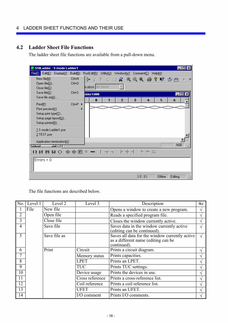
4.2 Ladder Sheet File Functions The ladder sheet file functions are available from a pull-down menu.
The file functions are described below.
No. Level 1 Level 2 Level 3 Description 4α1 File New file Opens a window to create a new program. √2 Open file Reads a specified program file. √3 Close file Closes the window currently active. √4 Save file Saves data in the window currently active
(editing can be continued). √
5 Save file as Saves all data for the window currently active as a different name (editing can be continued).
√
6 Print Circuit Prints a circuit diagram. √7 Memory status Prints capacities. √8 LPET Prints an LPET. √9 TUC Prints TUC settings. √10 Device usage Prints the devices in use. √11 Cross reference Prints a cross-reference list. √12 Coil reference Prints a coil reference list. √13 UFET Prints an UFET. √14 I/O comment Prints I/O comments. √

4 LADDER SHEET FUNCTIONS AND THEIR USE
- 19 -
No. Level 1 Level 2 Level 3 Description 4α15 Print preview Circuit Displays a print image of a circuit
diagram. √
16 Memory status Displays a print image of a system capacity.
√
17 LPET Displays a print image of an LPET. √18 TUC Displays a print image of TUC settings. √19 Device usage Displays a print image of the devices in
use. √
20 Cross reference Displays a print image of a cross reference list.
√
21 Coil reference Displays a print image of a coil reference list.
√
22 UFET Displays a print image of a UFET. √23 I/O comment Displays a print image of I/O comments. √24 Setup print type Sets details for a print job. √25 Setup page layout Sets a page layout. √26 Setup printer Sets up a printer. √27 File names 1, 2, ... Displays the names of files used
previously. √
28
File (continued from the previous page)
Application termination
Terminates the application involved. √
√: Supported LPET: Ladder program entry table TUC: Timer one-shot counter UFET: User function entry table
4 LADDER SHEET FUNCTIONS AND THEIR USE
- 20 -
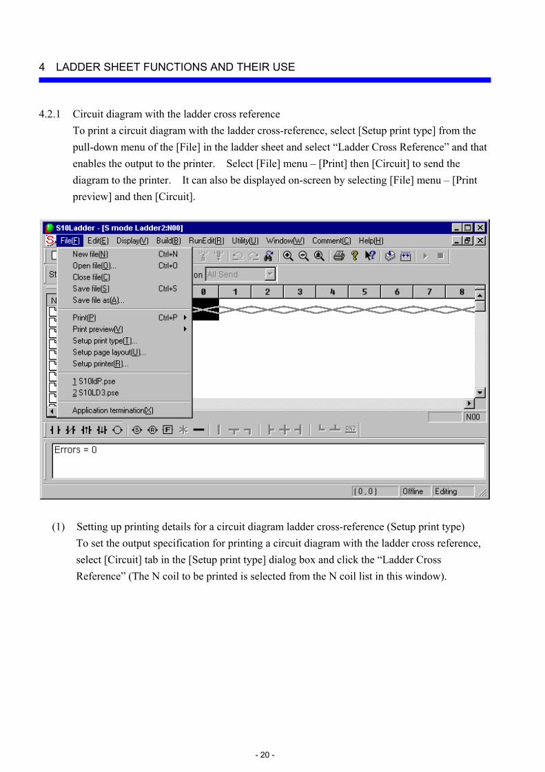
4.2.1 Circuit diagram with the ladder cross reference To print a circuit diagram with the ladder cross-reference, select [Setup print type] from the pull-down menu of the [File] in the ladder sheet and select “Ladder Cross Reference” and that enables the output to the printer. Select [File] menu – [Print] then [Circuit] to send the diagram to the printer. It can also be displayed on-screen by selecting [File] menu – [Print preview] and then [Circuit].
(1) Setting up printing details for a circuit diagram ladder cross-reference (Setup print type) To set the output specification for printing a circuit diagram with the ladder cross reference, select [Circuit] tab in the [Setup print type] dialog box and click the “Ladder Cross Reference” (The N coil to be printed is selected from the N coil list in this window).
4 LADDER SHEET FUNCTIONS AND THEIR USE
- 21 -
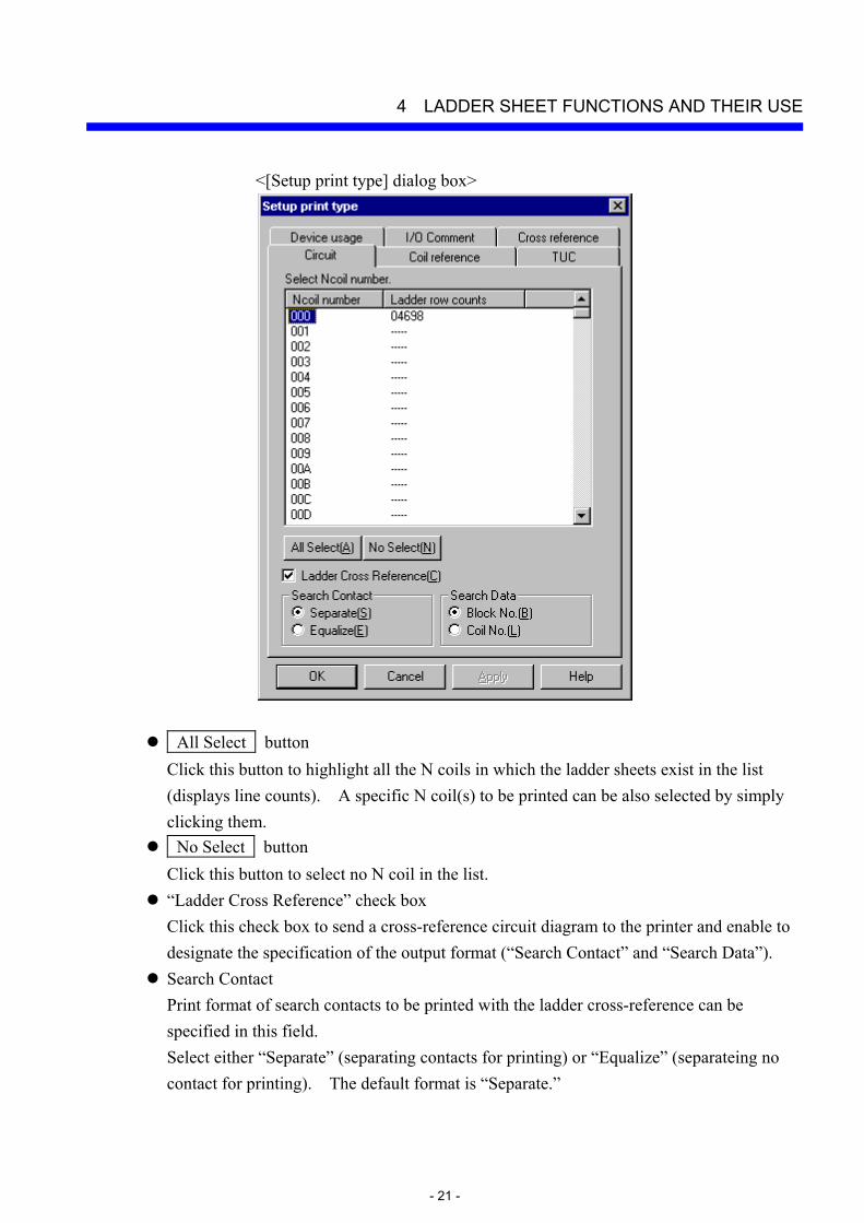
<[Setup print type] dialog box>
All Select button Click this button to highlight all the N coils in which the ladder sheets exist in the list (displays line counts). A specific N coil(s) to be printed can be also selected by simply clicking them. No Select button Click this button to select no N coil in the list. “Ladder Cross Reference” check box Click this check box to send a cross-reference circuit diagram to the printer and enable to designate the specification of the output format (“Search Contact” and “Search Data”). Search Contact Print format of search contacts to be printed with the ladder cross-reference can be specified in this field. Select either “Separate” (separating contacts for printing) or “Equalize” (separateing no contact for printing). The default format is “Separate.”
4 LADDER SHEET FUNCTIONS AND THEIR USE
- 22 -
Search Data This field specifies an outputting method of search results. Select either “Block No.” (outputting in block numbers) or “Coil No.” (outputting in coil numbers). The default output method is “Block No.”
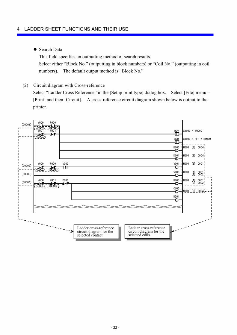
(2) Circuit diagram with Cross-reference
Select “Ladder Cross Reference” in the [Setup print type] dialog box. Select [File] menu – [Print] and then [Circuit]. A cross-reference circuit diagram shown below is output to the printer.
Ladder cross-reference circuit diagram for the selected coils
Ladder cross-reference circuit diagram for the selected contact

4 LADDER SHEET FUNCTIONS AND THEIR USE
- 23 -
(Note 1) Cross-reference items to be printed (printing to contact/coil) Cross-references to be output to the circuit diagram are corresponding to the output coils in the ladder program as listed below.
<Cross-reference items to be printed>
Symbol Printed or Not printed
: Keep Relay Reset coil Printed
: Keep Relay Set coil Printed
: Output coil (*1) Printed
: Arithmetic function Not printed
(Note 2) Cross-reference printable items (printing to coil)
A table below is a list of cross-reference printable items when printing a circuit diagram.
No. Item Print format Remarks 1 Nesting numbers using a
coil register N*** ***: 3 digits in hexadecimal
2 Type of symbols using a coil register
[A]: Contact A [C]: Coil (*2) [B]: Contact B
Arithmetic functions are not printed.
3 Block numbers using a coil register
****: 4 digits in decimal
4 Name of the output coil block using a coil register
Name of the output coil (print a register that is used in a coil and register in the following format) printed in the format below
Example:
Arithmetic functions are not printed.
(*2) Printed out when a double coil is used between the nesting (A double coil can be used in nesting).
(*1) Output coils to be printed Y: External output R: Internal register M: Extended internal register T: On-delay timer U: One-shot timer C: Up-down counter G: Global link register N: Nesting coil P: Process register E: Event register Z: Z register
R050
R
S
F

4 LADDER SHEET FUNCTIONS AND THEIR USE
- 24 -
(Note 3) Cross-reference printable items (printing to contact) The following table is a list of cross-reference printable items when printing a circuit diagram.
No. Item Print format Remarks 1 Block number (circuit
number) that uses the same register as that used by contact as a coil.
<****>: 4 digits in decimal Only the coil used by the same nesting is to be printed. (*3)
(*3) For the block number of the target coil to be displayed under the contact, the coil used by the same nesting is to be printed and the coil used by another nesting is not printed. (Note 4) Printing format for cross-references (printing to coil)
You can specify any of the following printing formats for cross-reference printing (using the [Setup print type] dialog box). Search contact print format • This function specifies a print format of search contacts to be printed with the
ladder cross-reference. • Select either “Separate” (separating contacts to print) or “Equalize” (separating
no contact to print). [Separate]
Contacts [A] and [B] of Y100 are separately printed.
Y100 N000[A]0002 [B]0010
[Equalize]
Contacts [A] and [B] of Y100 are printed as a whole.
Y100 N000 : 0002 0010

4 LADDER SHEET FUNCTIONS AND THEIR USE
- 25 -
Search Data • This field specifies an outputting method of search results. • Select either “Block No.” (outputting with block numbers) or “Coil No.”
(outputting with coil numbers). The default output method is “Block No.” [Block No.]
Y100 N000[A]0002
[B]0010
[Coil No.]
All the output coil names of the blocks with the contact points searched will be printed.
Y100 N000[A] R043 [B] Y20C
(Note 5) Printing format for cross-reference (printing to contact) The printing format is fixed as shown below. The block number (circuit number) that uses the same register as that used by the specified contact as a coil is printed in < > under the contact (contact A or contact B).
Y000
<0003>
R000
<0004>

4 LADDER SHEET FUNCTIONS AND THEIR USE
- 26 -
4.3 Ladder Sheet Edit Functions The ladder sheet edit functions are selectable from the symbol bar and a pull-down menu. The basic procedure required for using these functions is:
(1) Select a ladder symbol (such as contact A) and paste it in the desired position on a ladder sheet. (2) Set parameters for the pasted ladder symbol. (3) Perform editing by repeating Steps (1) and (2) or by specifying a line or a range of lines in the
sheet.
4 LADDER SHEET FUNCTIONS AND THEIR USE
- 27 -
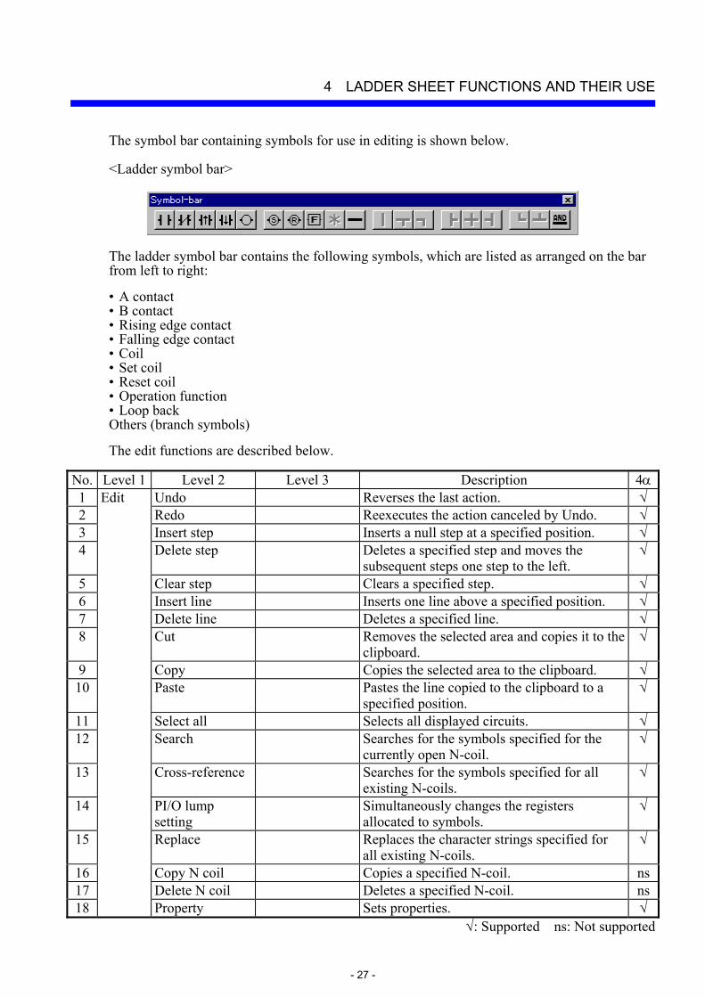
The symbol bar containing symbols for use in editing is shown below. <Ladder symbol bar>
The ladder symbol bar contains the following symbols, which are listed as arranged on the bar from left to right: • A contact • B contact • Rising edge contact • Falling edge contact • Coil • Set coil • Reset coil • Operation function • Loop back Others (branch symbols)
The edit functions are described below.
No. Level 1 Level 2 Level 3 Description 4α1 Edit Undo Reverses the last action. √2 Redo Reexecutes the action canceled by Undo. √3 Insert step Inserts a null step at a specified position. √4 Delete step Deletes a specified step and moves the
subsequent steps one step to the left. √
5 Clear step Clears a specified step. √6 Insert line Inserts one line above a specified position. √7 Delete line Deletes a specified line. √8 Cut Removes the selected area and copies it to the
clipboard. √
9 Copy Copies the selected area to the clipboard. √10 Paste Pastes the line copied to the clipboard to a
specified position. √
11 Select all Selects all displayed circuits. √12 Search Searches for the symbols specified for the
currently open N-coil. √
13 Cross-reference Searches for the symbols specified for all existing N-coils.
√
14 PI/O lump setting
Simultaneously changes the registers allocated to symbols.
√
15 Replace Replaces the character strings specified for all existing N-coils.
√
16 Copy N coil Copies a specified N-coil. ns17 Delete N coil Deletes a specified N-coil. ns18 Property Sets properties. √
√: Supported ns: Not supported

4 LADDER SHEET FUNCTIONS AND THEIR USE
- 28 -
4.3.1 Pasting ladder symbols There are several methods of pasting ladder symbols to sheets. Select the desired method.
(1) Pasting at the input cursor position with the mouse
Click the desired symbol on the symbol bar. The symbol will then be pasted at the symbol cursor position.
(2) Pasting with keys
A symbol can be pasted by a specified combination of key strokes at the symbol cursor position on the sheet. To move the symbol cursor, use the [←], [→], [↑], and [↓] arrow keys. Key strokes can be customized by selecting [Utility] menu – [Keyboard]. <[Customize the key position of symbol.] window>
4 LADDER SHEET FUNCTIONS AND THEIR USE
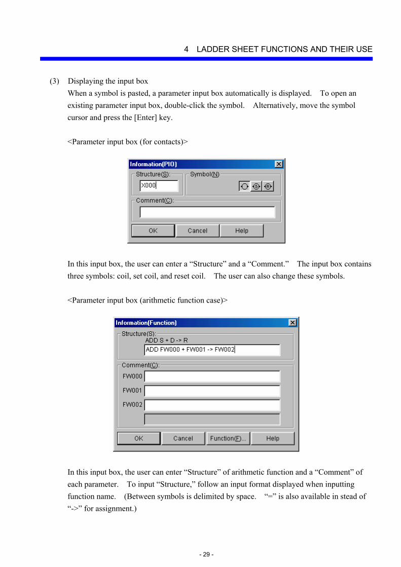
- 29 -
(3) Displaying the input box When a symbol is pasted, a parameter input box automatically is displayed. To open an existing parameter input box, double-click the symbol. Alternatively, move the symbol cursor and press the [Enter] key. <Parameter input box (for contacts)>
In this input box, the user can enter a “Structure” and a “Comment.” The input box contains three symbols: coil, set coil, and reset coil. The user can also change these symbols. <Parameter input box (arithmetic function case)>
In this input box, the user can enter “Structure” of arithmetic function and a “Comment” of each parameter. To input “Structure,” follow an input format displayed when inputting function name. (Between symbols is delimited by space. “=” is also available in stead of “->” for assignment.)
4 LADDER SHEET FUNCTIONS AND THEIR USE
- 30 -
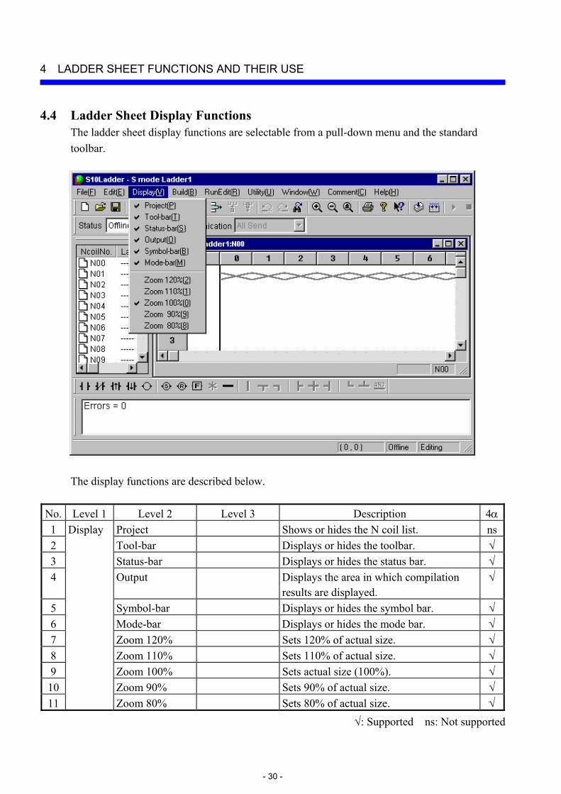
4.4 Ladder Sheet Display Functions The ladder sheet display functions are selectable from a pull-down menu and the standard toolbar.
The display functions are described below.
No. Level 1 Level 2 Level 3 Description 4α1 Display Project Shows or hides the N coil list. ns2 Tool-bar Displays or hides the toolbar. √3 Status-bar Displays or hides the status bar. √4 Output Displays the area in which compilation
results are displayed. √
5 Symbol-bar Displays or hides the symbol bar. √6 Mode-bar Displays or hides the mode bar. √7 Zoom 120% Sets 120% of actual size. √8 Zoom 110% Sets 110% of actual size. √9 Zoom 100% Sets actual size (100%). √10 Zoom 90% Sets 90% of actual size. √11 Zoom 80% Sets 80% of actual size. √
√: Supported ns: Not supported
4 LADDER SHEET FUNCTIONS AND THEIR USE
- 31 -
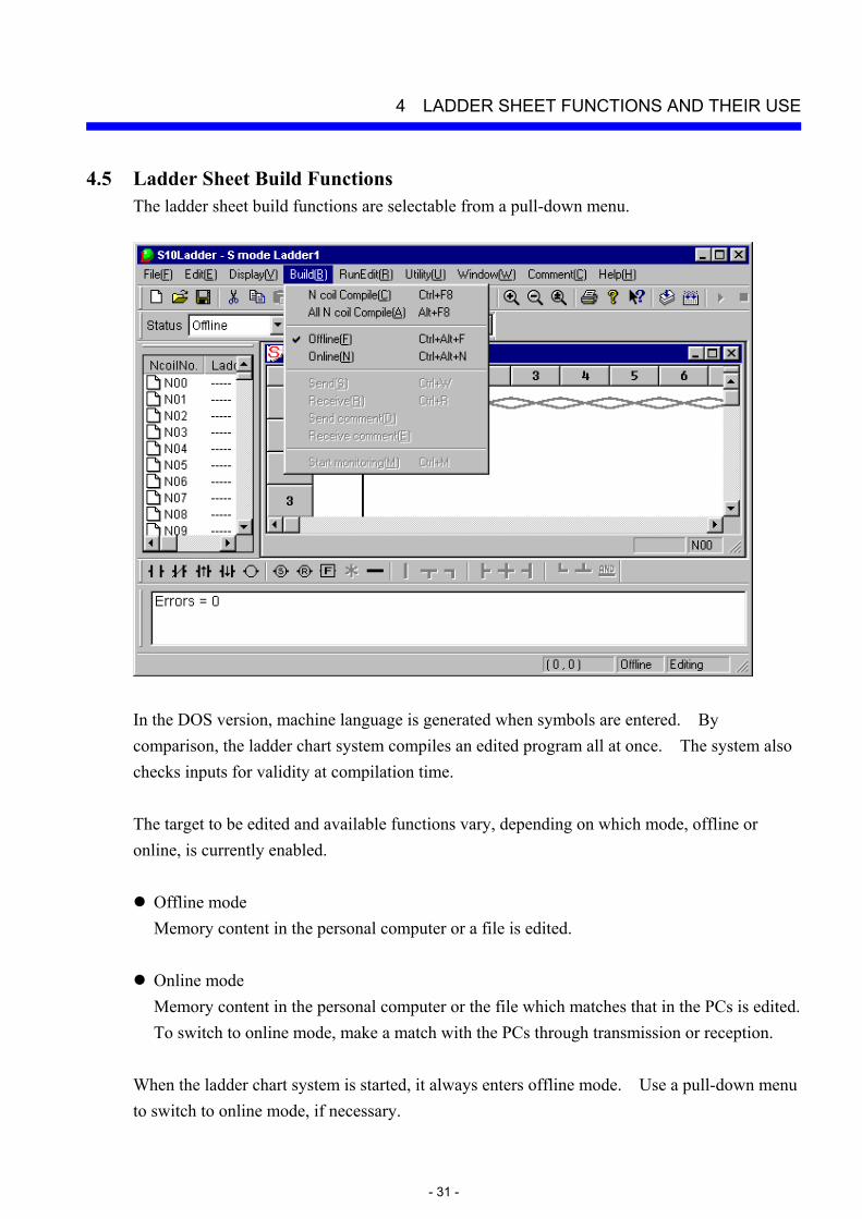
4.5 Ladder Sheet Build Functions The ladder sheet build functions are selectable from a pull-down menu.
In the DOS version, machine language is generated when symbols are entered. By comparison, the ladder chart system compiles an edited program all at once. The system also checks inputs for validity at compilation time. The target to be edited and available functions vary, depending on which mode, offline or online, is currently enabled.
Offline mode Memory content in the personal computer or a file is edited.
Online mode Memory content in the personal computer or the file which matches that in the PCs is edited. To switch to online mode, make a match with the PCs through transmission or reception.
When the ladder chart system is started, it always enters offline mode. Use a pull-down menu to switch to online mode, if necessary.
4 LADDER SHEET FUNCTIONS AND THEIR USE
- 32 -
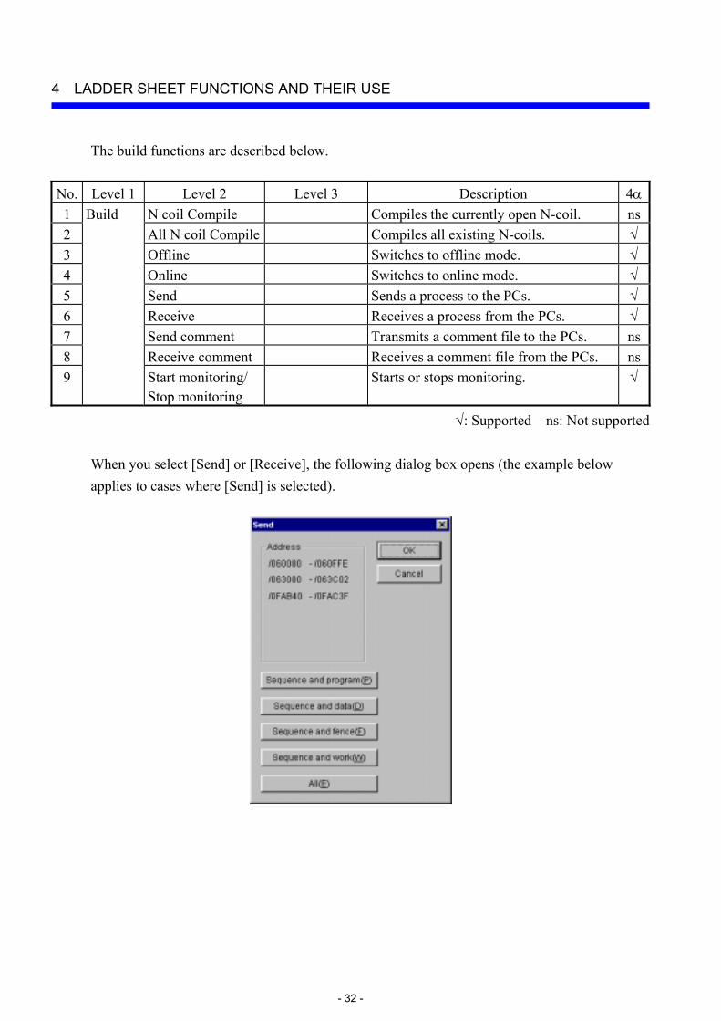
The build functions are described below. No. Level 1 Level 2 Level 3 Description 4α1 Build N coil Compile Compiles the currently open N-coil. ns2 All N coil Compile Compiles all existing N-coils. √3 Offline Switches to offline mode. √4 Online Switches to online mode. √5 Send Sends a process to the PCs. √6 Receive Receives a process from the PCs. √7 Send comment Transmits a comment file to the PCs. ns8 Receive comment Receives a comment file from the PCs. ns9 Start monitoring/
Stop monitoring Starts or stops monitoring. √
√: Supported ns: Not supported
When you select [Send] or [Receive], the following dialog box opens (the example below applies to cases where [Send] is selected).
4 LADDER SHEET FUNCTIONS AND THEIR USE
- 33 -
From the [Send] dialog box, select the area to be transmitted or received, and then click the OK button. Transmission or reception then takes place. The contents of the areas to be transmitted/received are shown below: • Sequence (ladder program, ladder management area, SQET, TUC setting, and user
mathematical/logical function) • Sequence + data (sequence + DW register) • Sequence + fence (sequence + DW register + ladder program free space) • Sequence + work (sequence + DW register + ladder program free space + FW/BI register) • All areas (sequence + DW register + ladder program free space + FW/BI register + registers
enumerated below) (Registers transmitted/received when all areas are selected: X, Y, J, Q, G, R, M, K, T, U, C, N, P, V, E, Z, and S, of which T, U, and C are contacts.)
Any ladder chart system on a network has a lock function compatible with that network. This is to prevent multiple such ladder diagram systems from accessing the same PC simultaneously. When online mode is specified, the connected PCs are locked. The locked PCs are unlocked when offline mode is specified. Online mode may be specified for the PCs that are already locked by the ladder chart system on another personal computer. When this happens, an error message is displayed and the specified online mode is invalidated. (As for the 4α series, only connection to the RS-232C interface is supported and thus the lock feature is not available.)
4 LADDER SHEET FUNCTIONS AND THEIR USE
- 34 -
4.5.1 2α and S10mini series ladder chart four-line simultaneous monitoring function Ladder chart system versions 7 and later (system floppy disk versions 07-00 and later) support the four-line simultaneous monitoring function that is exercised via an Ethernet. This function enables four personal computers to conduct simultaneous ladder chart monitoring operations with respect to one CPU unit. For the use of this feature, the monitoring ladder chart system (program product type: S-7890-34) is required in addition to the ladder chart system. This feature is not supported for the 4α series. The requirements for the use of the four-line simultaneous monitoring function are indicated below with a typical configuration.
(1) Requirements
• The version of the employed ET.NET module must be as indicated below: LWE550: Version 4, Revision 1 or later (2α series) LQE020: Version 3, Revision 1 or later (S10mini series)
• The PCs must be connected to personal computers via Ethernet (the function supporting this is not available if the RS-232C or GP-IB interface is used).
• The PCs must be connected to personal computers via a LAN (the function supporting this is not available through the use of a one-to-one direct connection).
• Up to four personal computers can be simultaneously connected to the PCs. However, only one ladder chart editing personal computer (regular ladder chart system) must be used. The other personal computers must be dedicated to monitoring (up to three monitoring ladder chart system machines can be used).
(2) Limitations
Even when two ET.NET modules (main module and submodule) are connected to one CPU unit, up to four personal computers can be connected to that CPU unit.

4 LADDER SHEET FUNCTIONS AND THEIR USE
- 35 -
(3) Typical configuration
Transceiver
S10/2α or S10mini CPU unit
Transceiver cable
CPU
10BASE-5 cable
Hub
10BASE-T cable 10BASE-T cable
Transceiver cable
ET.NET module
Ladder chart editing personal computer (Ladder chart system)
Monitoring personal computer 1 (Monitoring ladder chart system)
Monitoring personal computer 2 (Monitoring ladder chart system)
Monitoring personal computer 3 (Monitoring ladder chart system)
4 LADDER SHEET FUNCTIONS AND THEIR USE
- 36 -
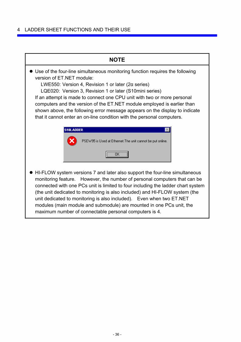
NOTE
Use of the four-line simultaneous monitoring function requires the following version of ET.NET module:
LWE550: Version 4, Revision 1 or later (2α series) LQE020: Version 3, Revision 1 or later (S10mini series)
If an attempt is made to connect one CPU unit with two or more personal computers and the version of the ET.NET module employed is earlier than shown above, the following error message appears on the display to indicate that it cannot enter an on-line condition with the personal computers.
HI-FLOW system versions 7 and later also support the four-line simultaneous monitoring feature. However, the number of personal computers that can be connected with one PCs unit is limited to four including the ladder chart system (the unit dedicated to monitoring is also included) and HI-FLOW system (the unit dedicated to monitoring is also included). Even when two ET.NET modules (main module and submodule) are mounted in one PCs unit, the maximum number of connectable personal computers is 4.
4 LADDER SHEET FUNCTIONS AND THEIR USE
- 37 -
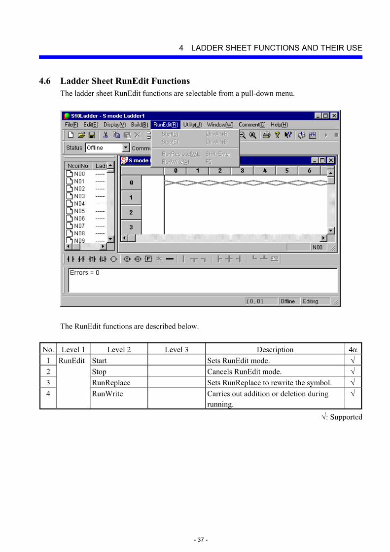
4.6 Ladder Sheet RunEdit Functions The ladder sheet RunEdit functions are selectable from a pull-down menu.
The RunEdit functions are described below.
No. Level 1 Level 2 Level 3 Description 4α1 RunEdit Start Sets RunEdit mode. √ 2 Stop Cancels RunEdit mode. √ 3 RunReplace Sets RunReplace to rewrite the symbol. √ 4 RunWrite Carries out addition or deletion during
running. √
√: Supported

4 LADDER SHEET FUNCTIONS AND THEIR USE
- 38 -
The [RunReplace] and [RunWrite] submenus are described below. RunReplace: Existing symbols (contacts and coils) are rewritten without having to stop the PCs.
Branch instructions cannot be changed. Also, circuits cannot be deleted or added. To change branch instructions or add or delete circuits, use the [RunWrite] submenu. Move the cursor to the symbol the user wants to rewrite, and select the [RunReplace] option from the pulldown menu. The input box to modify a symbol will then appear. After modifying the symbol, click the Rewrite button in the input box and thereby transmit the modified information to the PCs. <Input box for rewriting during running>
RunWrite: Existing circuits are rewritten. Branch instructions can be changed. Circuits
can also be deleted or added. After modifying a circuit, select the [RunWrite] option from the pulldown menu. The modified information will then be transmitted to the PCs. In the 2αH, 2αHf, and S10mini series, circuits are rewritten without having to stop the PCs. In the 2α, 2αE, and 4α series, the PCs are stopped while the modified information is being transmitted.

4 LADDER SHEET FUNCTIONS AND THEIR USE
- 39 -
4.7 Ladder Sheet Utility Functions The ladder sheet utility functions are selectable from a pull-down menu.
The utility functions are described below.
No. Level 1 Level 2 Level 3 Description 4α1 Keyboard Sets a shortcut for a combination of
keystrokes to enter a symbol. √
2 Setup environment
Sets the colors in which the window for each state is displayed.
√
3 Change connection of PCs
Sets a type of communication with the PCs.
√
4 Free occupancy Forcibly unlocks the PCs. ns 5 MCS Reads or writes memory in the PCs. √ 6 Time chart
monitor Displays a timing chart monitoring window.
√
7 Matrix monitor Displays the matrix monitor. √ 8
Monitor control status
Register monitor
Displays a numeric-value monitoring window.
√
9 Change capacity
Sets conditions and an environment required for execution on the PCs.
√
10 Analog counter Registers or deletes data that controls an analog counter or pulse counter.
√
11
Utility
PCs edition
Initiate PCs memory
Restores memory in the PCs to its initial condition.
√
√: Supported ns: Not supported

4 LADDER SHEET FUNCTIONS AND THEIR USE
- 40 -
No. Level 1 Level 2 Level 3 Description 4α12 FD Reads or writes a file to the floppy
disk. √
13 PRET Registers or deletes a PRET. ns 14 UFET Registers or deletes a UFET. √ 15 LPET Displays the contents of an LPET. √ 16 DIFF Compares ladder chart circuits and
displays its result. √
17 PCs status Displays the status of PCs. ns 18 Operation
history Displays the history of remote operations.
ns
19 RUN Executes a ladder program. ns 20 STOP Stops a ladder program. ns 21
Utility (continued from the previous page)
Remote operation
RESET Resets and restarts the PCs. ns √: Supported ns: Not supported
Free occupancy is related to the network-compatible function described in “4.5 Ladder Sheet Build Functions.” If the ladder chart system becomes disconnected for some reason from the PCs being locked by it, the PCs may be left locked and, as a result, may no longer be connected to any personal computer. In such a case, use the free occupancy function to forcibly release the PCs from the locked state. (As for the 4α series, the lock function is not supported, so the forcible unlock function is not supported either and thus is unavailable.)
NOTE
The free occupancy function can be executed even when another user is keeping the PCs locked. If it is executed in such a situation, the other user who has been keeping the PCs locked is not notified of the fact. This may cause multiple simultaneous accesses to the same PC in some operation. To prevent this, check for any warning message indicating that another user is keeping the PCs locked, before using the free occupancy function. If a ladder program created in the off-line state is transmitted to the PCs after the [Change capacity] or [Analog counter] setting is changed from [Utility] – [PCs edition] with the on-line state maintained with respect to the PCs, the setting entered during the off-line state overwrites the previous one. The reason is that the ladder program contains the settings for the PCs edition. If the setting is overwritten in the above manner, correct the setting in the on-line state.

4 LADDER SHEET FUNCTIONS AND THEIR USE
- 41 -
4.7.1 Ladder chart comparing function The ladder chart comparing function compares two ladder charts and displays a difference between them visually. When a ladder chart has been changed, this function permits checking different points from the previous ladder chart. The ladder chart comparing function is on the assumption that a ladder sheet is already displayed. For the display method, see “4.1 Creating Ladder Sheets” and “4.2 Ladder Sheet File Functions.” The ladder sheet that is already opened is a comparison source at comparison.
(1) Usage
To specify a file to be compared by the ladder chart comparing function, open the ladder sheet that already exists. Select [DIFF] in the [Utility] menu, and the [DIFF Setting] dialog box to open a target file to be compared will be displayed.
On the [DIFF Setting] dialog box, click the … button provided at the central right part of the window. The [Open] dialog box is displayed.
Select a target file to be compared and click the Open button.

4 LADDER SHEET FUNCTIONS AND THEIR USE
- 42 -
The selected file is displayed in the [File Name] field of the [DIFF Setting] dialog box.
Click the Cancel button, and the dialog box will be closed automatically. Select the DIFF button, and the dialog box will be closed and [Nesting DIFF List] will be displayed.
[Nesting DIFF List] displays whether any DIFF exists or not as a result of comparison for every nesting. If there is any difference for each nesting, “Different” is displayed. If not, “Identical” is displayed. To quit [Nesting DIFF List], click the × button provided at the upper right part of the window.

4 LADDER SHEET FUNCTIONS AND THEIR USE
- 43 -
In the title of [Nesting DIFF List], the file name to be compared and the total number of different nestings are displayed. The following operations permit saving the nesting DIFF list in a text-format file. ① When [Nesting DIFF List] is displayed, select [Save file] from the [File] menu, select
[Save file as] from the [File] menu, or press the [Ctrl] + [S] keys. ② The [Save file as] dialog box is displayed. ③ Specify the file and save it.
Double-clicking [Different] in [Nesting DIFF List] displays the [Circuit DIFF] window.
In the window title, the selected Nesting No., file name of comparison destination, and Different Count (comparison source: comparison target) are displayed. The number displayed at the leftmost of the window is a ladder sheet circuit number or a target file circuit number and has one of the following meanings depending on the corresponding color.
No. Comparison result Display color Circuit No. to be displayed 1 The same circuit White Comparison target circuit No.2 A circuit exists for the ladder sheet. Yellow Ladder sheet circuit No. 3 A circuit exists for the comparison target. Red Comparison target circuit No.
To quit the [Circuit DIFF] window, click the × button provided in the upper right part of the window. After quitting it, you can also possible to select another nesting in [Nesting DIFF List] to display the [Circuit DIFF] window.

4 LADDER SHEET FUNCTIONS AND THEIR USE
- 44 -
(2) Limitations While a ladder sheet is edited, this function is not available. Be sure to compile the ladder sheet and then use the ladder chart comparing function.
4 LADDER SHEET FUNCTIONS AND THEIR USE
- 45 -
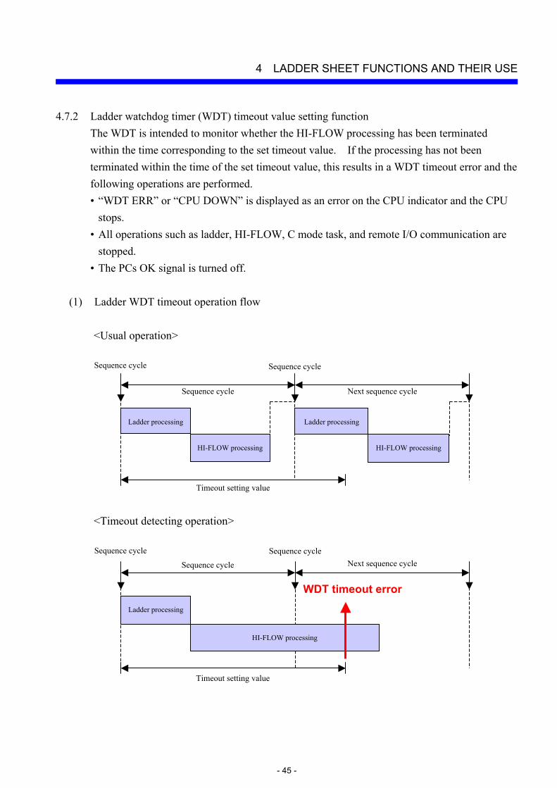
4.7.2 Ladder watchdog timer (WDT) timeout value setting function The WDT is intended to monitor whether the HI-FLOW processing has been terminated within the time corresponding to the set timeout value. If the processing has not been terminated within the time of the set timeout value, this results in a WDT timeout error and the following operations are performed. • “WDT ERR” or “CPU DOWN” is displayed as an error on the CPU indicator and the CPU
stops. • All operations such as ladder, HI-FLOW, C mode task, and remote I/O communication are
stopped. • The PCs OK signal is turned off.
(1) Ladder WDT timeout operation flow
<Usual operation>
<Timeout detecting operation>
Ladder processing
Sequence cycle
HI-FLOW processing
Next sequence cycle
Sequence cycle Sequence cycle
Ladder processing
HI-FLOW processing
Timeout setting value
Ladder processing
Sequence cycle Next sequence cycle Sequence cycle Sequence cycle
Timeout setting value
HI-FLOW processing
WDT timeout error
4 LADDER SHEET FUNCTIONS AND THEIR USE
- 46 -
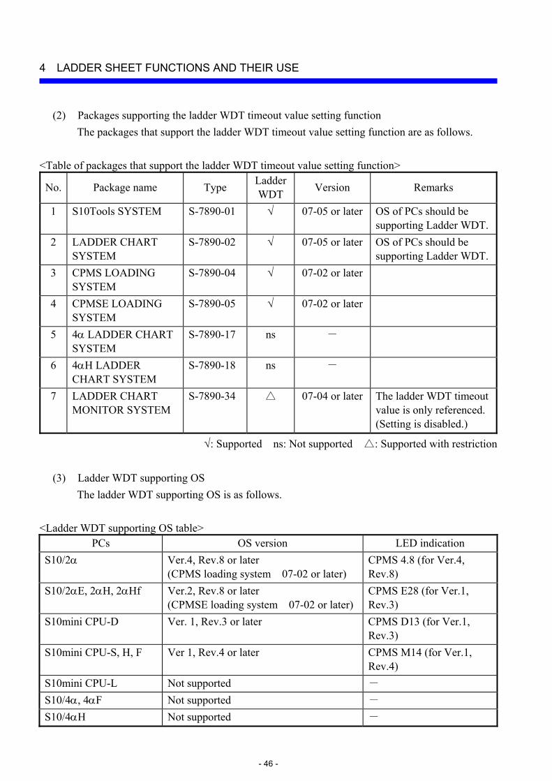
(2) Packages supporting the ladder WDT timeout value setting function The packages that support the ladder WDT timeout value setting function are as follows.
<Table of packages that support the ladder WDT timeout value setting function>
No. Package name Type LadderWDT Version Remarks
1 S10Tools SYSTEM S-7890-01 √ 07-05 or later OS of PCs should be supporting Ladder WDT.
2 LADDER CHART SYSTEM
S-7890-02 √ 07-05 or later OS of PCs should be supporting Ladder WDT.
3 CPMS LOADING SYSTEM
S-7890-04 √ 07-02 or later
4 CPMSE LOADING SYSTEM
S-7890-05 √ 07-02 or later
5 4α LADDER CHART SYSTEM
S-7890-17 ns -
6 4αH LADDER CHART SYSTEM
S-7890-18 ns -
7 LADDER CHART MONITOR SYSTEM
S-7890-34 △ 07-04 or later The ladder WDT timeout value is only referenced. (Setting is disabled.)
√: Supported ns: Not supported △: Supported with restriction
(3) Ladder WDT supporting OS The ladder WDT supporting OS is as follows.
<Ladder WDT supporting OS table>
PCs OS version LED indication S10/2α Ver.4, Rev.8 or later
(CPMS loading system 07-02 or later) CPMS 4.8 (for Ver.4, Rev.8)
S10/2αE, 2αH, 2αHf Ver.2, Rev.8 or later (CPMSE loading system 07-02 or later)
CPMS E28 (for Ver.1, Rev.3)
S10mini CPU-D Ver. 1, Rev.3 or later CPMS D13 (for Ver.1, Rev.3)
S10mini CPU-S, H, F Ver 1, Rev.4 or later CPMS M14 (for Ver.1, Rev.4)
S10mini CPU-L Not supported - S10/4α, 4αF Not supported - S10/4αH Not supported -
4 LADDER SHEET FUNCTIONS AND THEIR USE
- 47 -
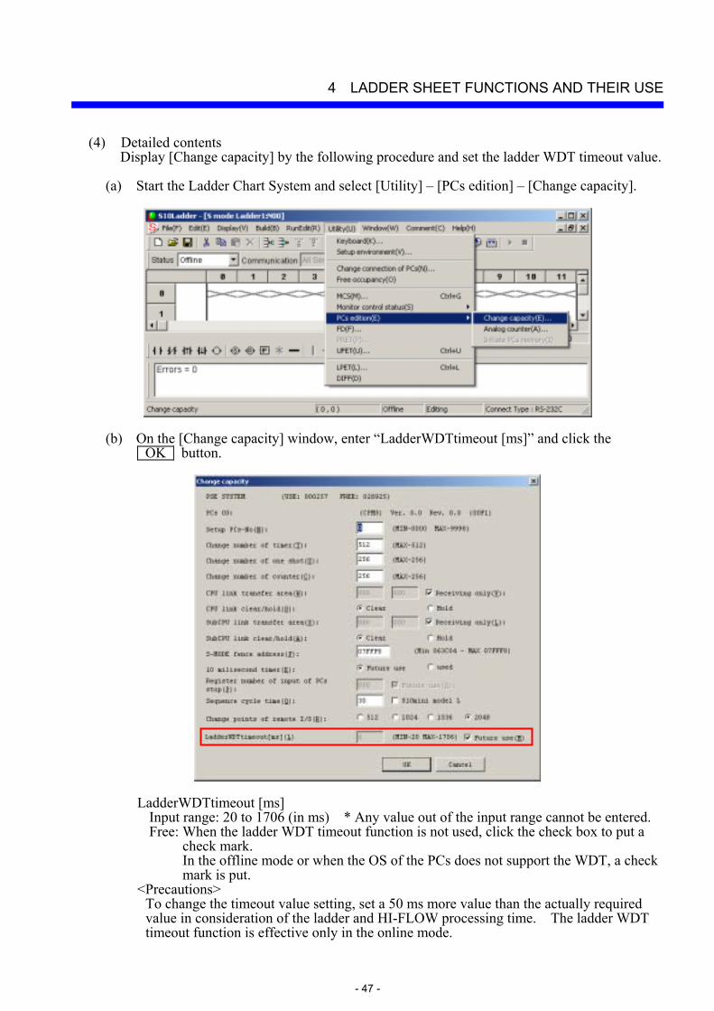
(4) Detailed contents Display [Change capacity] by the following procedure and set the ladder WDT timeout value.
(a) Start the Ladder Chart System and select [Utility] – [PCs edition] – [Change capacity].
(b) On the [Change capacity] window, enter “LadderWDTtimeout [ms]” and click the OK button.
LadderWDTtimeout [ms] Input range: 20 to 1706 (in ms) * Any value out of the input range cannot be entered. Free: When the ladder WDT timeout function is not used, click the check box to put a
check mark. In the offline mode or when the OS of the PCs does not support the WDT, a check mark is put.
<Precautions> To change the timeout value setting, set a 50 ms more value than the actually required value in consideration of the ladder and HI-FLOW processing time. The ladder WDT timeout function is effective only in the online mode.
4 LADDER SHEET FUNCTIONS AND THEIR USE
- 48 -
4.7.3 Setting the analog and pulse counter modules In some cases when a remote I/O uses a 4-ch analog I/O module, pulse counter module, or 8-ch analog input module (for the S10mini series only), you must implement a setting in the [Analog counter] window of the Ladder Chart System. (May be unnecessary, depending on the mode setting.) When information is registered in the [Analog counter] window, the system sets analog values obtained from external inputs in the EW area of PIO memory and writes the content of the EW area in external outputs.
(1) Mode setting
(a) 4-ch analog I/O module
To use a 4-ch analog I/O module in the MODE2 setting, you must register it in the [Analog counter] window of the Ladder Chart System. Conversely, to use the 4-ch analog I/O module in the MODE1 setting, you must not register it in the [Analog counter] window. For more information about the mode setting and 4-ch analog I/O module, see the manuals below.
S10/2α series and S10/4α series: HARDWARE MANUAL I/O 4 CHANNEL
ANALOG/PULSE COUNTER (manual number SAE-2-201)
S10mini series: S10mini HARDWARE MANUAL I/O MODULE (manual number SME-1-114)
(b) Pulse counter module
To use a pulse counter module, you must register it in the [Analog counter] window of the Ladder Chart System. For more information about the pulse counter module, see the manuals below.
S10/2α series and S10/4α series: HARDWARE MANUAL I/O 4 CHANNEL
ANALOG/PULSE COUNTER (manual number SAE-2-201)
S10mini series: S10mini HARDWARE MANUAL I/O MODULE (manual number SME-1-114)
(c) Scanning-type analog input module
To use a scanning-type analog input module, you must register it in the [Analog counter] window of the Ladder Chart System. For more information about the scanning-type analog input module, see “HARDWARE MANUAL I/O MODULE (manual number SME-1-114).”

4 LADDER SHEET FUNCTIONS AND THEIR USE
- 49 -
(d) 8-ch analog input module To use an 8-ch analog input module in the MODE2 or MODE4 setting, you must register it in the [Analog counter] window of the Ladder Chart System. When setting MODE2 or MODE4, select and set a module shown below in the [Analog counter] window.
<When using the module in the MODE2 setting>
<When using Channels 0 to 3 in the MODE4 setting>
Note: You cannot set to use Channels 4 to 7 without using Channels 0 to 3.
<When using Channels 0 to 7 in the MODE4 setting>
First select “LQA050, LQA150 (MODE4) (ch0 - ch3) (AI)” from the Module Name list box and set it. Then select “LQA050, LQA150 (MODE4) (ch4 - ch7) (AI)” from the Module Name list box and set it. Set “LQA050, LQA150 (MODE4) (ch4 - ch7) (AI)” immediately after the registration number of “LQA050, LQA150 (MODE4) (ch0 - ch3) (AI).”
Select this module.
Select this module.
First select and set this module.Then select and set this module.

4 LADDER SHEET FUNCTIONS AND THEIR USE
- 50 -
When “LQA050, LQA150 (MODE4) (ch4 - ch7)AI” is set for a registration number that does not immediately follow a registration number in use [for example, setting “LQA050, LQA150 (MODE4) (ch4 - ch7) (AI)” for No.4 instead of No.3 before which “LQA050, LQA150 (MODE4) (ch0 - ch3) (AI)” has been registered], the following error message dialog box appears.
For the MODE1 or MODE3 setting, you must not implement the registration in the [Analog counter] window. For more information about the mode setting, see “HARDWARE MANUAL I/O MODULE (manual number SME-1-114).” Note: This function is not available for the S10/2α series and the S10/4α series. Unlike
the conventional 8-ch analog input modules (LWA000, LWA001, LWA002, LWA003, LWA020, LWA021, and LWA022), these 8-ch analog input modules (LQA050 and LQA150) can be registered in the EW area.
When selecting this number for registration.
4 LADDER SHEET FUNCTIONS AND THEIR USE
- 51 -
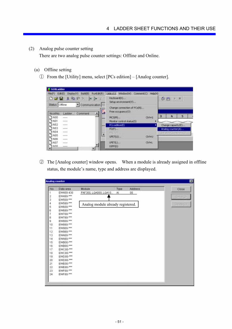
(2) Analog pulse counter setting There are two analog pulse counter settings: Offline and Online.
(a) Offline setting
① From the [Utility] menu, select [PCs edition] – [Analog counter].
② The [Analog counter] window opens. When a module is already assigned in offline status, the module’s name, type and address are displayed.
Analog module already registered.

4 LADDER SHEET FUNCTIONS AND THEIR USE
- 52 -
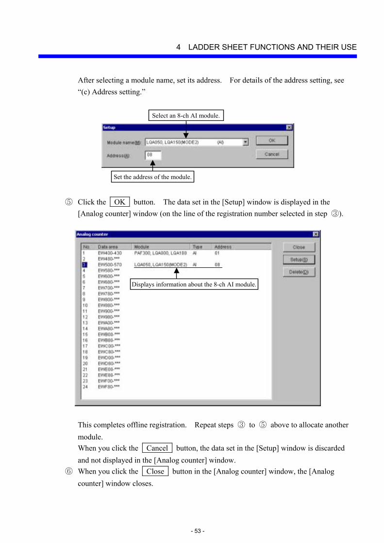
③ Select the registration number of an allocation data area in the [Analog counter] window, then click the Setup button.
④ The [Setup] window opens. Select the name of a module that you want to allocate from
the Module name list box. When you select an 8-ch analog input module as the module name, the allocation data range changes from 4-ch to 8-ch. The default allocation data area is 4-ch.
Select an allocation data area.
When clicked, the module name list opens.
4 LADDER SHEET FUNCTIONS AND THEIR USE
- 53 -
After selecting a module name, set its address. For details of the address setting, see “(c) Address setting.”
⑤ Click the OK button. The data set in the [Setup] window is displayed in the
[Analog counter] window (on the line of the registration number selected in step ③).
This completes offline registration. Repeat steps ③ to ⑤ above to allocate another module. When you click the Cancel button, the data set in the [Setup] window is discarded and not displayed in the [Analog counter] window.
⑥ When you click the Close button in the [Analog counter] window, the [Analog counter] window closes.
Displays information about the 8-ch AI module.
Set the address of the module.
Select an 8-ch AI module.
4 LADDER SHEET FUNCTIONS AND THEIR USE
- 54 -
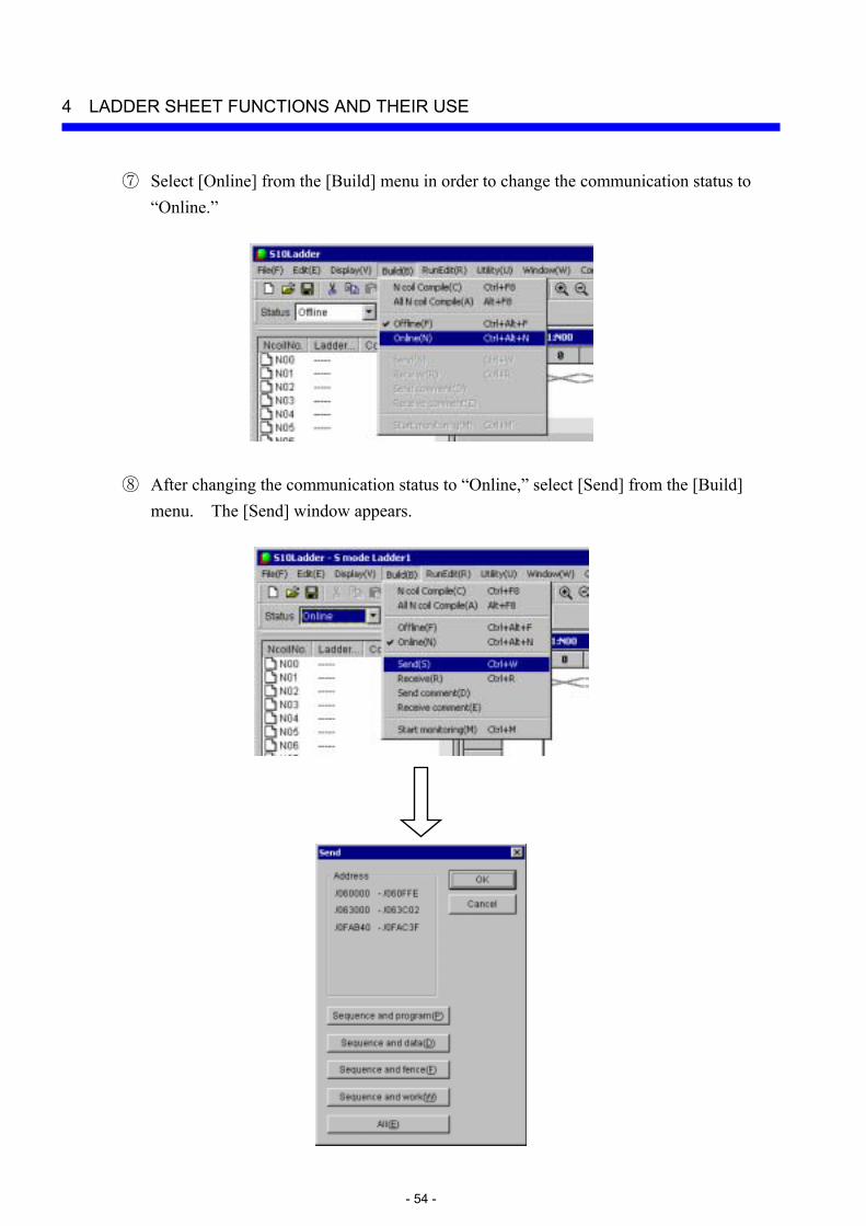
⑦ Select [Online] from the [Build] menu in order to change the communication status to “Online.”
⑧ After changing the communication status to “Online,” select [Send] from the [Build] menu. The [Send] window appears.
4 LADDER SHEET FUNCTIONS AND THEIR USE
- 55 -
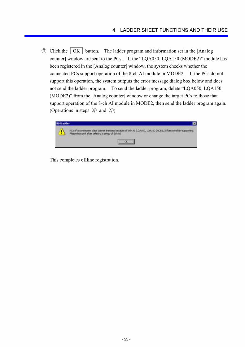
⑨ Click the OK button. The ladder program and information set in the [Analog counter] window are sent to the PCs. If the “LQA050, LQA150 (MODE2)” module has been registered in the [Analog counter] window, the system checks whether the connected PCs support operation of the 8-ch AI module in MODE2. If the PCs do not support this operation, the system outputs the error message dialog box below and does not send the ladder program. To send the ladder program, delete “LQA050, LQA150 (MODE2)” from the [Analog counter] window or change the target PCs to those that support operation of the 8-ch AI module in MODE2, then send the ladder program again. (Operations in steps ⑧ and ⑨)
This completes offline registration.
4 LADDER SHEET FUNCTIONS AND THEIR USE
- 56 -
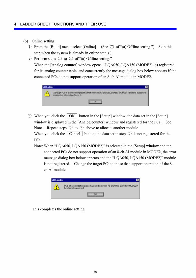
(b) Online setting ① From the [Build] menu, select [Online]. (See ⑦ of “(a) Offline setting.”) Skip this
step when the system is already in online status.) ② Perform steps ① to ④ of “(a) Offline setting.”
When the [Analog counter] window opens, “LQA050, LQA150 (MODE2)” is registered for its analog counter table, and concurrently the message dialog box below appears if the connected PCs do not support operation of an 8-ch AI module in MODE2.
③ When you click the OK button in the [Setup] window, the data set in the [Setup] window is displayed in the [Analog counter] window and registered for the PCs. See Note. Repeat steps ② to ③ above to allocate another module. When you click the Cancel button, the data set in step ② is not registered for the PCs. Note: When “LQA050, LQA150 (MODE2)” is selected in the [Setup] window and the
connected PCs do not support operation of an 8-ch AI module in MODE2, the error message dialog box below appears and the “LQA050, LQA150 (MODE2)” module is not registered. Change the target PCs to those that support operation of the 8-ch AI module.
This completes the online setting.
4 LADDER SHEET FUNCTIONS AND THEIR USE
- 57 -
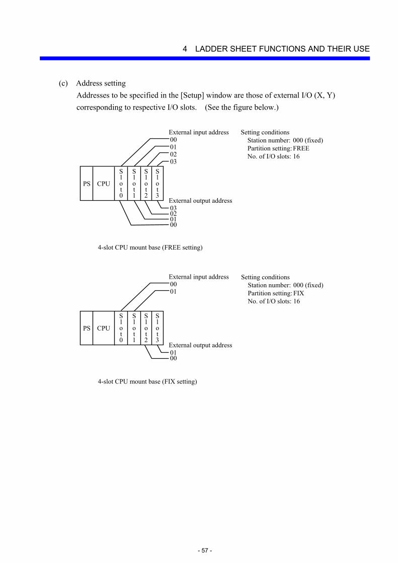
(c) Address setting Addresses to be specified in the [Setup] window are those of external I/O (X, Y) corresponding to respective I/O slots. (See the figure below.)
4-slot CPU mount base (FREE setting)
PS CPU
Slot0
03020100External input address
External output address03020100
Setting conditions Station number: 000 (fixed) Partition setting: FREE No. of I/O slots: 16
S l o t 1
S l o t 2
S l o t 3
4-slot CPU mount base (FIX setting)
PS CPU
Slot0
0100External input address
External output address0100
S l o t 1
S l o t 2
S l o t 3
Setting conditions Station number: 000 (fixed) Partition setting: FIX No. of I/O slots: 16

4 LADDER SHEET FUNCTIONS AND THEIR USE
- 58 -
The external I/O addresses are not respectively fixed to each I/O slot, but are dependent on the RI/O station numbers, I/O point settings, and partition settings (FREE or FIX). For details, see “S10mini HARDWARE MANUAL CPU (manual number SME-1-100).”
4-slot I/O mount base (FREE setting)
PS RI/O
S l o t 0
43424140External input address
External output address43424140
Setting conditions Station number: 040 (Variable) Partition setting: FREE No. of I/O slots: 16
S l o t 1
S l o t 2
S l o t 3
4-slot I/O mount base (FIX setting)
PS RI/O
S l o t 0
4140External input address
External output address4140
S l o t 1
S l o t 2
S l o t 3
Setting conditions Station number: 040 (Variable) Partition setting: FIX No. of I/O slots: 16
4 LADDER SHEET FUNCTIONS AND THEIR USE
- 59 -
(3) Deleting an analog pulse counter
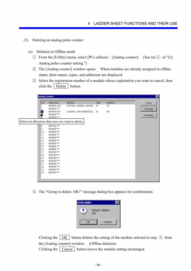
(a) Deletion in Offline mode ① From the [Utility] menu, select [PCs edition] – [Analog counter]. (See (a)-① of “(2)
Analog pulse counter setting.”) ② The [Analog counter] window opens. When modules are already assigned in offline
status, their names, types, and addresses are displayed. ③ Select the registration number of a module whose registration you want to cancel, then
click the Delete button.
④ The “Going to delete. OK?” message dialog box appears for confirmation.
Clicking the OK button deletes the setting of the module selected in step ③ from the [Analog counter] window. (Offline deletion) Clicking the Cancel button leaves the module setting unchanged.
Select an allocation data area you want to delete.
4 LADDER SHEET FUNCTIONS AND THEIR USE
- 60 -
⑤ When you click the Close button in the [Analog counter] window, the [Analog counter] window closes.
⑥ Select [Online] from the [Build] menu in order to change the communication status to “Online.” (See (a)-⑦ of “(2) Analog pulse counter setting.”)
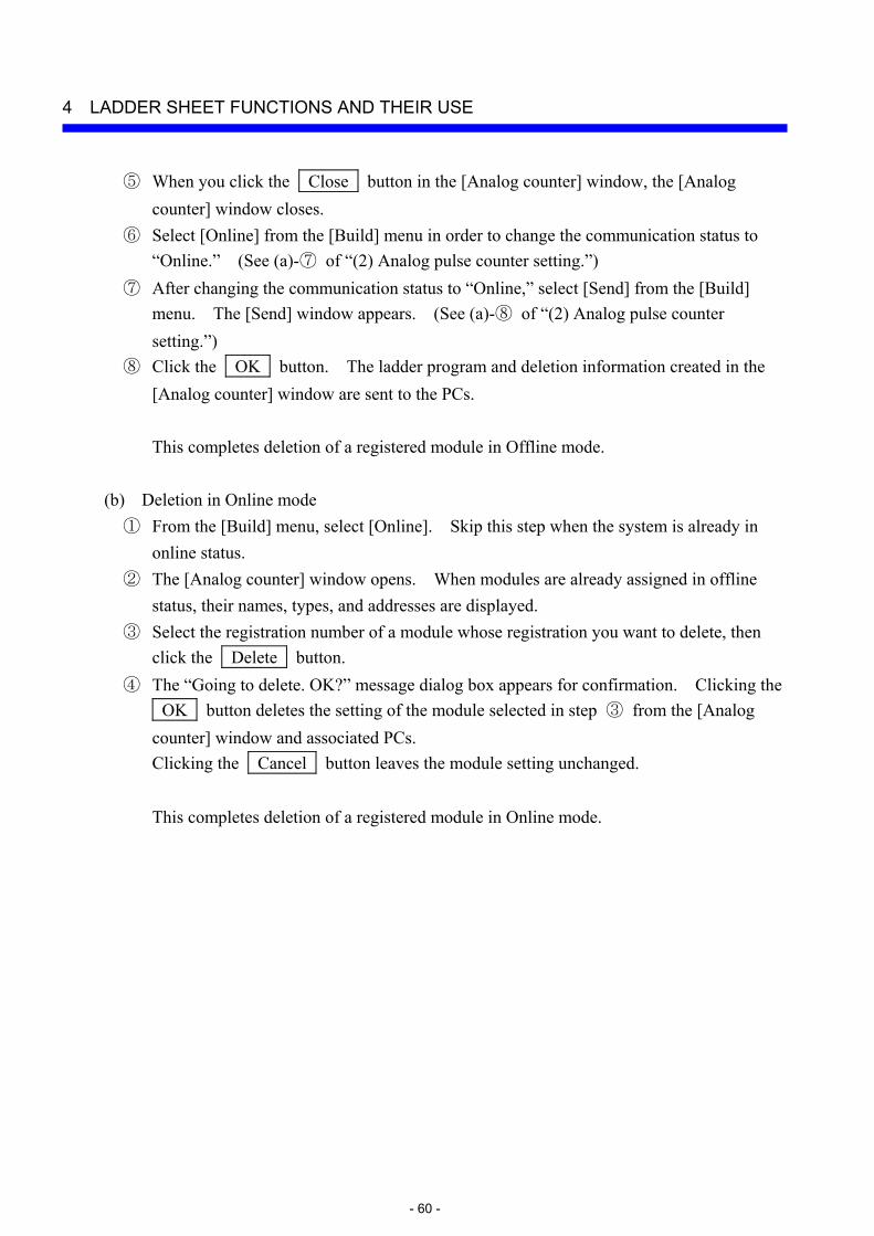
⑦ After changing the communication status to “Online,” select [Send] from the [Build] menu. The [Send] window appears. (See (a)-⑧ of “(2) Analog pulse counter setting.”)
⑧ Click the OK button. The ladder program and deletion information created in the [Analog counter] window are sent to the PCs.
This completes deletion of a registered module in Offline mode.
(b) Deletion in Online mode
① From the [Build] menu, select [Online]. Skip this step when the system is already in online status.
② The [Analog counter] window opens. When modules are already assigned in offline status, their names, types, and addresses are displayed.
③ Select the registration number of a module whose registration you want to delete, then click the Delete button.
④ The “Going to delete. OK?” message dialog box appears for confirmation. Clicking the OK button deletes the setting of the module selected in step ③ from the [Analog counter] window and associated PCs. Clicking the Cancel button leaves the module setting unchanged.
This completes deletion of a registered module in Online mode.
4 LADDER SHEET FUNCTIONS AND THEIR USE
- 61 -
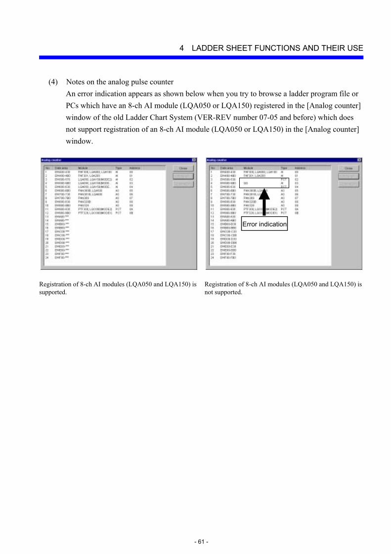
(4) Notes on the analog pulse counter An error indication appears as shown below when you try to browse a ladder program file or PCs which have an 8-ch AI module (LQA050 or LQA150) registered in the [Analog counter] window of the old Ladder Chart System (VER-REV number 07-05 and before) which does not support registration of an 8-ch AI module (LQA050 or LQA150) in the [Analog counter] window.
Registration of 8-ch AI modules (LQA050 and LQA150) is supported.
Registration of 8-ch AI modules (LQA050 and LQA150) is not supported.
Error indication
4 LADDER SHEET FUNCTIONS AND THEIR USE
- 62 -
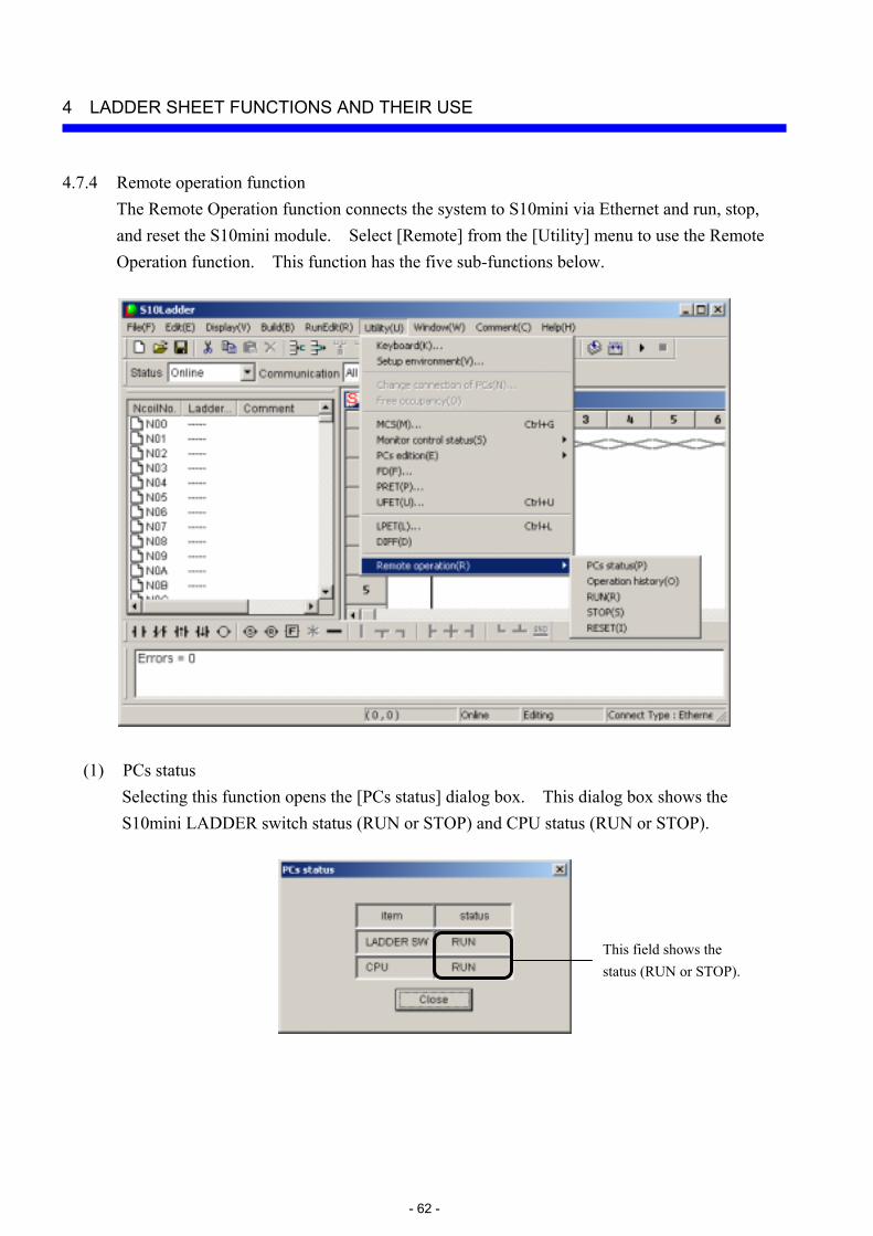
4.7.4 Remote operation function The Remote Operation function connects the system to S10mini via Ethernet and run, stop, and reset the S10mini module. Select [Remote] from the [Utility] menu to use the Remote Operation function. This function has the five sub-functions below.
(1) PCs status Selecting this function opens the [PCs status] dialog box. This dialog box shows the S10mini LADDER switch status (RUN or STOP) and CPU status (RUN or STOP).
This field shows the status (RUN or STOP).

4 LADDER SHEET FUNCTIONS AND THEIR USE
- 63 -
(2) Operation History This function shows the history of remote operation requests (up to 42 of the latest) received by the ET.NET module. A history example is shown below.
(3) RUN Selecting this function opens the dialog box below.
Click the OK button to bring the CPU into RUN status from STOP status. When the CPU enters RUN status, the dialog box below appears.

4 LADDER SHEET FUNCTIONS AND THEIR USE
- 64 -
(4) STOP Selecting this function opens the dialog box below.
Click the OK button to bring the CPU to STOP status from RUN status. When the CPU enters STOP status, the dialog box below appears.
(5) RESET Selecting this function opens the dialog box below.
Click the OK button to reset the CPU. When the CPU is reset, the dialog box below appears.

4 LADDER SHEET FUNCTIONS AND THEIR USE
- 65 -
The following explains the relationship among LADDER switch status, CPU status (RUN/STOP), and remote operations of S10mini.
Remote RUN and Remote STOP operations The CPU status can only be controlled as shown below when the LADDER switch is set to the RUN position. If you try to control the CPU status with the LADDER switch set to the STOP position, an error dialog box appears.
Remote RESET operation The remote RESET operation is always enabled independently of the LADDER switch position and CPU status.
<Notes on using the Remote Operation function>
Note the following when using the Remote Operation function: • The Remote Operation menu is displayed only on the Ladder Chart System of the 2α and
S10mini series. This menu is not displayed on the 4α and 4αH Ladder Chart Systems. • Select “Ethernet” as the type of PC communication. • To use the Remote Operation function, set “ONLINE” and confirm that Ethernet
communication is normal. • Do not set the MODE No. switch of the ET.NET module to “5” (setting of tool
communication by 10BASE-T as a submodule) to use the Remote Operation function. • The Remote Operation function is available only when using the Ethernet modules below
for connection. When other Ethernet modules are used, the respective Remote Maintenance menus are displayed as being inactive. LQE020: Module Rev R (micro program version 5.0) or later LQE520: Module Rev H (micro program version 7.0) or later
• The Ethernet modules above can be mounted on the 2α series by using an optional adapter (LWZ800), but cannot remotely operate the 2α series.
CPU RUN status
CPU STOP status
Remote STOP operation
Remote RUN operation
4 LADDER SHEET FUNCTIONS AND THEIR USE
- 66 -
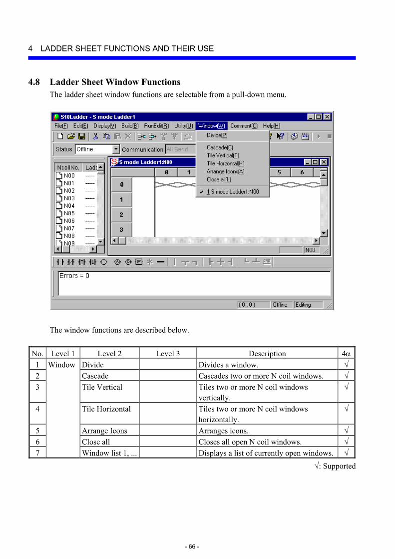
4.8 Ladder Sheet Window Functions The ladder sheet window functions are selectable from a pull-down menu.
The window functions are described below.
No. Level 1 Level 2 Level 3 Description 4α1 Window Divide Divides a window. √2 Cascade Cascades two or more N coil windows. √3 Tile Vertical Tiles two or more N coil windows
vertically. √
4 Tile Horizontal Tiles two or more N coil windows horizontally.
√
5 Arrange Icons Arranges icons. √6 Close all Closes all open N coil windows. √7 Window list 1, ... Displays a list of currently open windows. √
√: Supported

4 LADDER SHEET FUNCTIONS AND THEIR USE
- 67 -
4.9 Ladder Sheet Comment Functions The ladder sheet comment functions are selectable from a pull-down menu.
The comment functions are described below.
No. Level 1 Level 2 Level 3 Description 4α1 Comment Initial Initializes comment information. √2 Open file Opens an existing comment file. √3 Save file Saves the comment file being processed. √4 Save file as Saves the comment file being processed as
a different name. √
5 Display Nothing Hides comments. √6 16 Strings Displays a comment in 16-character mode. √7 32 Strings Displays a comment in 32-character mode. √
√: Supported