Embed Size (px)
Citation preview

Not Your Fathers Heat Pump
OR WORKING WITH VARIABLE CAPACITY
HEAT PUMPS
ENERGY STAR CERTIFIED HOMES PARTNER MEETING,
2017
1

Fun Fact!
Home Efficiency Forum
Chance Masterson
How Not to Get Snake Bit: The Design
and Installation Process
3
Sizing and selection of equipment
Commissioning and controls
System design
Deciding Ducted or Ductless

Air Source Heat Pump
Zoology

Air source heat
pump
Style
Cold Climate
Compressor type
All Heat Pumps Air source heat pump
VRF Driven
Cold Climate
Central
Mini ducted
Point source
Cassette
DHP
Floor
Non Cold Climate
Conventional
Rotary/Piston
Non Cold Climate
CentralGas Back
Up

Modern Mini-splits
All inverter systems
Variable refrigerant flow
Ducted Systems
Low profile - horizontal
Ductless Systems
Wall Cassette
Floor mount
Ceiling Cassette
6
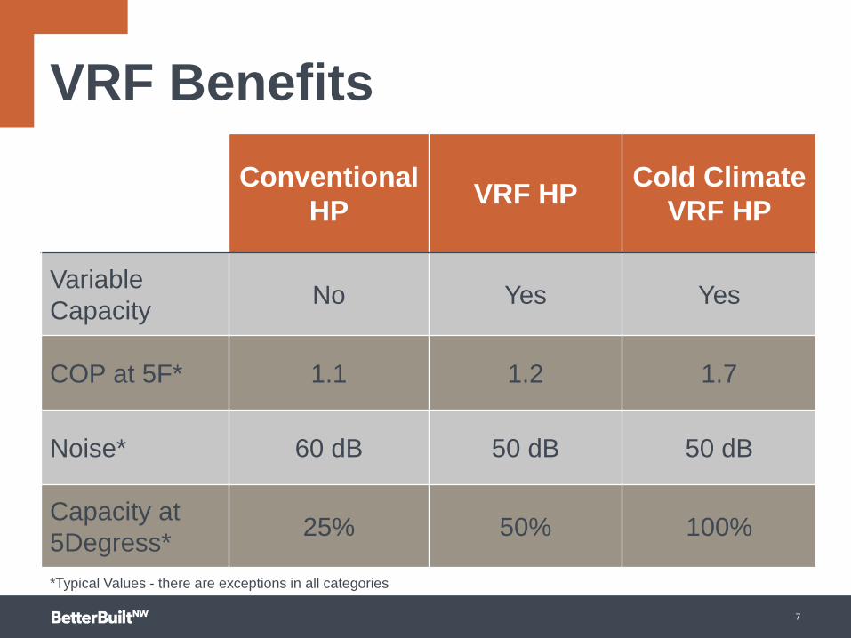
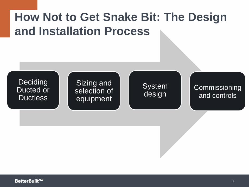
VRF Benefits
Conventional
HPVRF HP
Cold Climate
VRF HP
Variable
CapacityNo Yes Yes
COP at 5F* 1.1 1.2 1.7
Noise* 60 dB 50 dB 50 dB
Capacity at
5Degress*25% 50% 100%
7
*Typical Values - there are exceptions in all categories

Comfortable customers if you do it right!
8

Which are you thinking of?
Malort Face DHP Face
9

Alternatives to “lump on the wall”
10
Image courtesy of LG
Image courtesy of Mitsubishi

To Duct or not to Duct
That’s your first question
11

2,200 Sq. ft. House with a 12K DHP
25
35
45
55
65
75
85
02
/03
/12
15
:20
:00
.0
02
/03
/12
18
:35
:00
.0
02
/03
/12
21
:50
:00
.0
02
/04
/12
01
:05
:00
.0
02
/04
/12
04
:20
:00
.0
02
/04
/12
07
:35
:00
.0
02
/04
/12
10
:50
:00
.0
02
/04
/12
14
:05
:00
.0
02
/04
/12
17
:20
:00
.0
02
/04
/12
20
:35
:00
.0
02
/04
/12
23
:50
:00
.0
02
/05
/12
03
:05
:00
.0
02
/05
/12
06
:20
:00
.0
02
/05
/12
09
:35
:00
.0
02
/05
/12
12
:50
:00
.0
02
/05
/12
16
:05
:00
.0
02
/05
/12
19
:20
:00
.0
02
/05
/12
22
:35
:00
.0
02
/06
/12
01
:50
:00
.0
02
/06
/12
05
:05
:00
.0
02
/06
/12
08
:20
:00
.0
02
/06
/12
11
:35
:00
.0
02
/06
/12
14
:50
:00
.0
02
/06
/12
18
:05
:00
.0
02
/06
/12
21
:20
:00
.0
02
/07
/12
00
:35
:00
.0
02
/07
/12
03
:50
:00
.0
02
/07
/12
07
:05
:00
.0
02
/07
/12
10
:20
:00
.0
02
/07
/12
13
:35
:00
.0
02
/07
/12
16
:50
:00
.0
02
/07
/12
20
:05
:00
.0
02
/07
/12
23
:20
:00
.0
02
/08
/12
02
:35
:00
.0
02
/08
/12
05
:50
:00
.0
02
/08
/12
09
:05
:00
.0
02
/08
/12
12
:20
:00
.0
02
/08
/12
15
:35
:00
.0
02
/08
/12
18
:50
:00
.0
02
/08
/12
22
:05
:00
.0
02
/09
/12
01
:20
:00
.0
02
/09
/12
04
:35
:00
.0
02
/09
/12
07
:50
:00
.0
02
/09
/12
11
:05
:00
.0
02
/09
/12
14
:20
:00
.0
02
/09
/12
17
:35
:00
.0
02
/09
/12
20
:50
:00
.0
02
/10
/12
00
:05
:00
.0
02
/10
/12
03
:20
:00
.0
02
/10
/12
06
:35
:00
.0
Tem
p F
Master Guest Kitchen Office
House has low UA. Very tight. 12K ductless heat pump and low-efficiency ERV.
About 900 kWh/year for space heat.
12


Home Geometry and DHP Performance
Low Load House:
18K min-split
High Efficiency
HRV
What Could Go
Wrong?
15
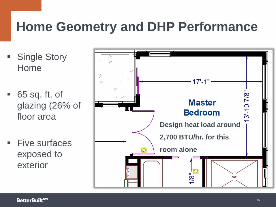
Design heat load around
2,700 BTU/hr. for this
room alone
Home Geometry and DHP Performance
Single Story
Home
65 sq. ft. of
glazing (26% of
floor area
Five surfaces
exposed to
exterior
16

POP QUIZ
Q: How much 70° F air must
you deliver to keep this room
at or set point or 68 degrees?
A: Too much
Avoid creating thermally
isolated rooms
Home Geometry and DHP Performance
17

Home Geometry and DHP Performance
Which home is best suited for a ducted inverter driven heat pump and
why?
18

SIZING AND SELECTION

Room by Room Loads
If a room has 15%
of the load, it
needs 15% of the
capacity
Without knowing
the room by room
heating and
cooling loads, you
can’t size the
system
20
0
20
40
60
80
100
120
-13 -4 5 10 17 25 30 35 40 47
% H
eating C
apacity
Outdoor Temperature F
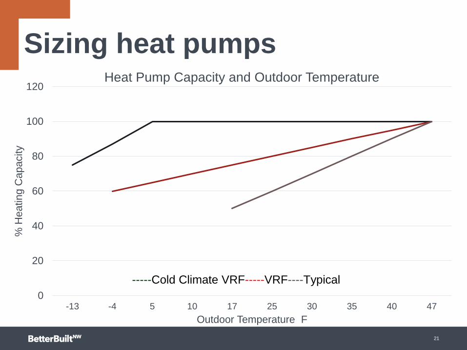
Heat Pump Capacity and Outdoor Temperature
-----Cold Climate VRF-----VRF----Typical
Sizing heat pumps
21

-
5,000
10,000
15,000
20,000
25,000
30,000
35,000
40,000
Ma
nu
fact
ure
r's
Sta
ted
He
ati
ng
Ca
pa
city
a
t 4
7 d
eg
F (
Btu
/hr)
Comparison of Nominal 2-ton DHP Models"Rated" Capacity
SIZING VARIABLE CAPACITY UNITSTurn Down Ratio: The ratio of the
highest output to the lowest output
22

0
200
400
600
800
1000
1200
1400
1600
1800
0
5000
10000
15000
20000
25000
30000
<0 0 - 9 10 to 19 20 to 24 25 to 29 30 to 35 35 to 39 40 to 44 45 to 49 50 to 54 55 to 59
H
o
u
r
s
i
n
T
e
m
p
B
i
n
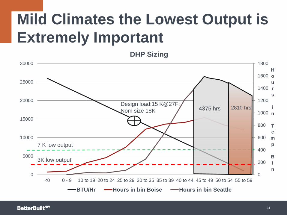
DHP Sizing
BTU/Hr Hours in bin Boise Hours in bin Seattle
Design load:24 K@9F
Nom Size 24K
10 K low output
4K low output
3300 hrs.
1529 hrs.
BOISE DHP— LOW OUTPUT SIZINGWhy Turn Down Ratios Matter
23
0
200
400
600
800
1000
1200
1400
1600
1800
0
5000
10000
15000
20000
25000
30000
<0 0 - 9 10 to 19 20 to 24 25 to 29 30 to 35 35 to 39 40 to 44 45 to 49 50 to 54 55 to 59
H
o
u
r
s
i
n
T
e
m
p
B
i
n
DHP Sizing
BTU/Hr Hours in bin Boise Hours in bin Seattle
Design load:15 K@27F:
Nom size 18K
7 K low output
3K low output
4375 hrs 2810 hrs
SEATTLE DHP— LOW OUTPUT SIZINGMild Climates the Lowest Output is
Extremely Important
24

SYSTEM DESIGN-NO DUCTS
25
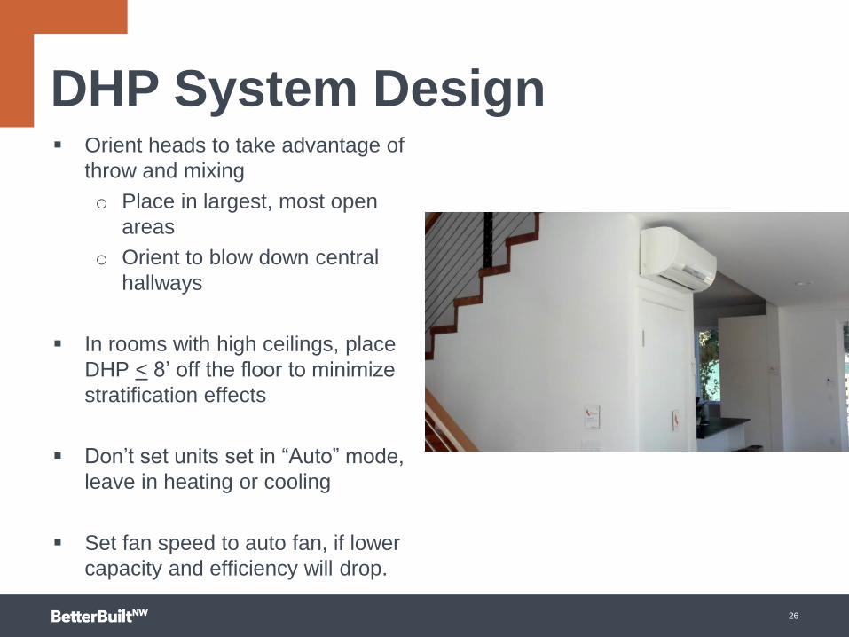
DHP System Design Orient heads to take advantage of
throw and mixing
o Place in largest, most open
areas
o Orient to blow down central
hallways
In rooms with high ceilings, place
DHP < 8’ off the floor to minimize
stratification effects
Don’t set units set in “Auto” mode,
leave in heating or cooling
Set fan speed to auto fan, if lower
capacity and efficiency will drop.
26
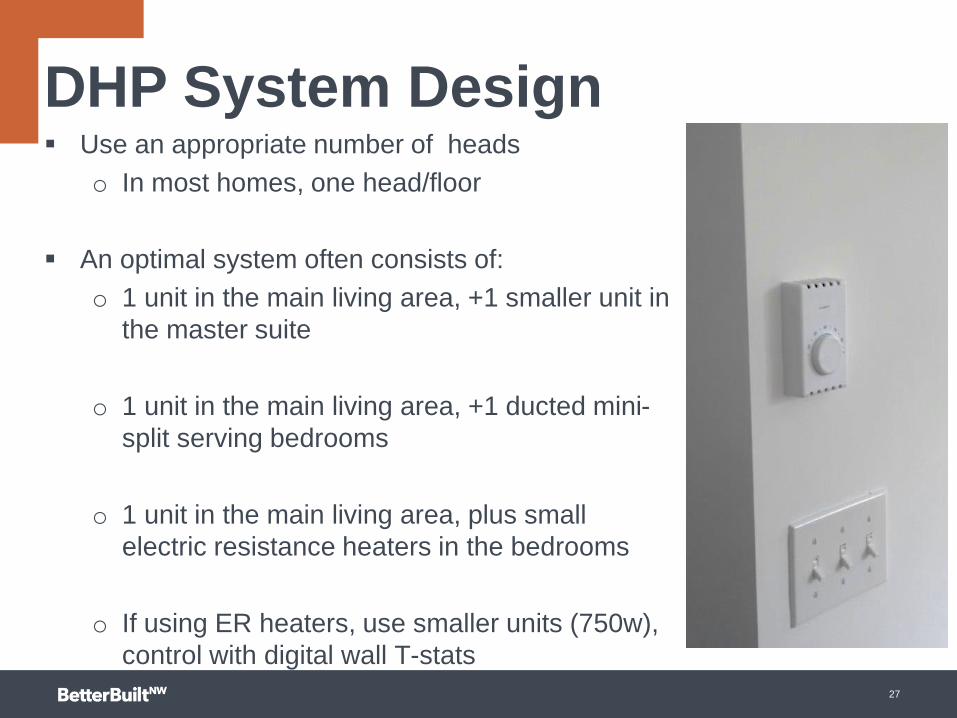
Use an appropriate number of heads
o In most homes, one head/floor
An optimal system often consists of:
o 1 unit in the main living area, +1 smaller unit in
the master suite
o 1 unit in the main living area, +1 ducted mini-
split serving bedrooms
o 1 unit in the main living area, plus small
electric resistance heaters in the bedrooms
o If using ER heaters, use smaller units (750w),
control with digital wall T-stats
27
DHP System Design

SYSTEM DESIGN-DUCTS

.50
Total ESP .50 IWC
Coil
Included in
heat pump fan
curve
Filter .12
Return
Grille.03
Supply
Grille.03
Total
Losses.18
Available
Static
Pressure
.32 IWC
The available static pressure is the amount of
pressure left over to overcome the resistance of
the duct system. Coils and filters have large
pressure drops.
29

ECMs
Are Not
Magic
Watts VS Static Pressure
0
100
200
300
400
500
600
700
800
900
0 0.2 0.4 0.6 0.8 1 1.2
Static Pressure
Watt
s PSC
ECM
30

Activity
31
What is the CFM in
the ultra low ESP
Setting at .08 I.W.C
on high speed?
What is the rated
flow?

Photo credit: http://www.masterfile.com/stock-photography/image/600-01791391/Aerial-View-
of-Freeway-Intersection-Highway-404-and-Finch-Avenue-Willowdale-Ontario-Canada
Moving air hates to make hard turns
32

Relax: We will show you a short cut
Step 1: Calculate the Total
Equivalent Length (TEL)
Step 2: Calculate the Available
Static Pressure
Step 3: Calculate the Friction
Rate
Step 4: Determine how much
air each duct section is
carrying
Step 5: Size the ducts
34
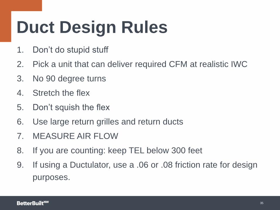
Duct Design Rules1. Don’t do stupid stuff
2. Pick a unit that can deliver required CFM at realistic IWC
3. No 90 degree turns
4. Stretch the flex
5. Don’t squish the flex
6. Use large return grilles and return ducts
7. MEASURE AIR FLOW
8. If you are counting: keep TEL below 300 feet
9. If using a Ductulator, use a .06 or .08 friction rate for design
purposes.
35
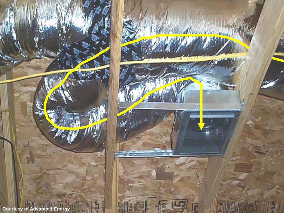
Courtesy of Advanced Energy

AVOID CONTROL
SYSTEM PITFALLS
THERMOSTATS/CONTROLLERS: NOT WHAT
YOU’RE COMFORTABLE WITH
38

jjj Setting the unit to sense
temperature at the T-stat:
Function 42 has to be set to
“01” and the t-stat icon has to
appear on the screen
High Insulation setting needs
to be activated
DUCTED MINI-SPLIT DESIGNFUNCTION 42 and Other Settings
39

Controller pitfalls explained
1. If using a wall-mounted controller, make sure it senses temperature at controller and not at air handler
2. If there is an option for efficient home, ensure it is selected.
1. Always set to high insulation setting
3. Read the manual
40

Commissioning
1. Put system in high heat or high cool mode if available
2. Measure external static pressure
3. Measure delivery at each register (if you have a flow hood)
4. Measure temperature
5. Conduct a duct leakage test if applicable
6. Check refrigerant charge against published values.
41
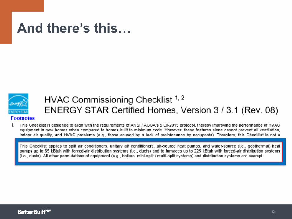
And there’s this…
42