Embed Size (px)
Citation preview

MUNICIPAL CONSULTATION FILING Connecticut General Statutes Section 16-50l (e)
FOR A
CERTIFICATE OF ENVIRONMENTAL COMPATIBILITY AND PUBLIC NEED
FOR THE
Northeast CT Reliability Project: Killingly 2G Substation
Killingly and Putnam, Connecticut
VOLUME 1 OF 2
PROJECT SUMMARY
September 2004

Table of Contents
A. SUMMARY DESCRIPTION AND LOCATION OF THE KILLINGLY 2G SUBSTATION.................................................................................................................. A-1
B. PURPOSE OF THE APPLICATION..............................................................................B-4 C. STATUTORY AUTHORITY FOR APPLICATION ................................................... C-1
C.1 Municipalities’ Participation During The Consultation Process..................... C-2 C.2 Description of Filing Contents ............................................................................ C-3
D. LEGAL NAME AND ADDRESS OF APPLICANT ..................................................... D-1 E. APPLICANT CONTACTS...............................................................................................E-1 F. DESCRIPTION OF FACILITY.......................................................................................F-1 G. NEED FOR FACILITY ................................................................................................... G-1 H. EXISTING CONDITIONS .............................................................................................. H-1
H.1. Existing Development .......................................................................................... H-1 H.2. Site Access............................................................................................................. H-1 H.3. Wetlands and Watercourses ............................................................................... H-2 H.4. Vegetation and Wildlife....................................................................................... H-3 H.5. Rare, Threatened, And Endangered Species..................................................... H-4 H.6. Water Supply Areas............................................................................................. H-5 H.7. Scenic Areas.......................................................................................................... H-6 H.8. Historic and Archaeological Resources ............................................................. H-6 H.9. Natural Resources................................................................................................ H-7 H.10. Floodplain Areas .................................................................................................. H-8 H.11. Recreational Areas............................................................................................... H-8 H.12. Seismic Areas........................................................................................................ H-8 H.13. Noise ...................................................................................................................... H-8 H.14. Lighting................................................................................................................. H-9 H.15. Other Statutory Facilities.................................................................................... H-9
I. SITE JUSTIFICATION .....................................................................................................I-1 J. SAFETY AND RELIABILITY INFORMATION.......................................................... J-1 K. EFFECTS ON THE ENVIRONMENT .......................................................................... K-1
K.1. Public Health and Safety ..................................................................................... K-1 K.2. Local, State and Federal Land Use Plans .......................................................... K-1 K.3. Existing and Future Development...................................................................... K-2 K.4. Roads..................................................................................................................... K-2 K.5. Wetlands ............................................................................................................... K-2 K.6. Wildlife and Vegetation....................................................................................... K-3 K.7. Water Supply Areas............................................................................................. K-4 K.8. Historic and Archaeological Resources ............................................................. K-5 K.9. Noise ...................................................................................................................... K-6 K.10 Floodplains............................................................................................................ K-7 K.11. Lighting................................................................................................................. K-7
L. MITIGATION MEASURES.............................................................................................L-1 M. HEALTH AND SAFETY................................................................................................ M-1
M.1 Electric and Magnetic Fields.............................................................................. M-1 M.2 Site Security......................................................................................................... M-2
N. A SCHEDULE OF THE PROPOSED PROGRAM FOR CONSTRUCTION, TESTING, AND OPERATION...................................................................................... N-1
LIST OF EXHIBITS ..................................................................................................................... I GENERAL GLOSSARY OF TERMS....................................................................................... II
i

List of Figures
Figure 1 – Location Map…………………………………………………….………………..A-3 Figure 2 – Artist Rendering……………………………………………………….………….F-3 Figure 3 – Transmission One-Line……………………………………………….………….G-2 Figure 4 – Surrounding Features…………………….…………………………..…………H-10 Figure 5 – Locations Evaluated……………………...……………………………………….I-2
ii

A. SUMMARY DESCRIPTION AND LOCATION OF THE KILLINGLY 2G
SUBSTATION
The eastern Connecticut transmission system (or “service area”) extends from the
Connecticut and Rhode Island border in a westerly direction for about 20 to 25 miles, from the
Connecticut and Massachusetts border in the north, and to Long Island Sound in the south. The
summer peak load in the area in 2004 was approximately 880 megawatts (MW). The majority of
the transmission system in the eastern Connecticut area is 115-kV with some 69-kV
transmission. Power is supplied to the area via three autotransformers and by local generation.
Two autotransformers are located at Montville (4J) Substation north of New London and the
third at Card Street (11F) Substation near Willimantic. The generation on the 115-kV lines is
connected at the Montville Substation (≈ 675MW) and an additional 100MW is located in the
vicinity of Norwich. Presently, there does not exist a connection between the 345-kV and 115-
kV transmission systems in Northeastern Connecticut. In addition, there is also no large
generator connected to the 115-kV system in Northeastern Connecticut. This is a critical
transmission system reliability concern which the proposed project would resolve.
Evaluation of the eastern Connecticut area using standard transmission planning criteria
resulted in future overloaded transmission lines, unacceptable low voltages, with the potential for
voltage collapse. In order to greatly improve transmission system reliability to the area, The
Connecticut Light and Power Company (CL&P) proposes to construct and install a new
345/115-kV substation with a 345/115-kV autotransformer. The proposed substation (to be
named “Killingly 2G Substation”) will be built on a portion of CL&P’s 33.2 acre property
located in the Towns of Putnam and Killingly. It will be built to not only improve the reliability
of the transmission system in eastern Connecticut, but it will be capable of supporting future
A-1
eastern Connecticut area load growth and other necessary 345-kV and 115-kV transmission
systems needs and expansion requirements. These may include such things as: installing a
second autotransformer, building for local area load growth, connection of Lake Road Station
generation into the 115-kV system, new 345-kV or 115-kV transmission lines, economically
beneficial projects, or other system needs or requirements.
Comprised of three separate and abutting parcels, the “Property” is identified as 193
Tracy Road (Lot 5, Map 34 in Killingly municipal assessor records) and 227-257 Park Road
(Lots 8 and 9, Map 119 in Putnam land records). Land use in the general vicinity includes a mix
of industrial, commercial and residential, and a transportation corridor (active railroad line and
Interstate 395). The Killingly 2G Substation would be located in the Town of Killingly,
northwest of the Staples warehouse distribution center. The nearest residence is located along
Park Road in Putnam approximately 1,100 feet to the east. Additional residences are located
along this road (which becomes Tracy Road in Killingly) primarily to the south. Figure 1 depicts
the location of the Property.
The northern portion of the Property is occupied by an operational 115-kV substation
(“Tracy 14M Substation”) and a former generating unit used primarily as a peaking facility
(currently two vacant, fence-enclosed concrete pads and a brick building). The peaking facility
historically operated only during high peak load demand periods and abnormal transmission
system events. Three overhead transmission lines traverse the Property, including one 345-kV
line (347) and two 115-kV lines (1505 and 1607). A number of 23-kV (Distribution) lines also
extend through portions of the Property. These 23-kV lines supply power to the local area’s
industrial, commercial and residential customers.
A-2

A-3

Once constructed, the Killingly 2G Substation would connect into the existing 345-kV overhead
transmission 347 line that inter-connects to the existing Sherman Road Substation in Rhode
Island and Lake Road Substation in Killingly, Connecticut. The Killingly 2G Substation would
also connect into the existing 115-kV overhead transmission 1607 and 1505 lines. These lines
presently inter-connect the Tracy 14M Substation in Putnam, Connecticut and the existing
Tunnel 12S Substation in Preston, Connecticut, with connections to the existing Fry Brook 13B
Substation in Plainfield, Connecticut, the Brooklyn 30Y Substation in Brooklyn, Connecticut,
and the Exeter 54N Substation in Sterling, Connecticut. Connecting to the existing 345-kV
overhead transmission line strengthens the eastern Connecticut service area transmission system,
improves reliability to withstand various system contingencies, provides capacity to serve
additional future load and allows for future system reliability and economically beneficial
projects to be built as the transmission system needs and requirements demand. The 345-kV and
115-kV transmission interconnections and associated equipment changes are a part of the
Killingly 2G Substation project. Connection of the Lake Road generation to the 115-kV system
is presently being evaluated and may become a proposed portion of this project as it proceeds
through the CSC application process.
A-4

B. PURPOSE OF THE APPLICATION
CL&P intends to apply to the Connecticut Siting Council (“CSC” or “the council”) for a
Certificate of Environmental Compatibility and Public Need (“Certificate”) for the Northeast
Connecticut Reliability Project (the “Project”), which consists primarily of the construction of
the Killingly 2G Substation and its access road in the Towns of Killingly and Putnam. The
purpose of the new Killingly 2G Substation is to provide increased transmission system
reliability for CL&P’s eastern Connecticut service area and support for future area load growth.
B-1

C. STATUTORY AUTHORITY FOR APPLICATION
Pursuant to the Public Utility Environmental Standards Act, Conn. Gen. Stat. § 16-50g
et seq., CL&P has an obligation to consult with all municipalities in which the primary or
alternative plans for a substation facility are proposed and all municipalities within 2,500 feet of
the proposed Substation facility. Specifically, Conn. Gen. Stat. § 16-50l(e) requires that:
At least sixty days prior to the filing of any application with the council, the
applicant shall consult with the municipality in which the facility may be located
and with any other municipality required to be served with a copy of the
application under subdivision (1) of subsection (b) of this section concerning the
proposed and alternative site locations of the facility. Such consultation with the
municipality shall include, but not be limited to good faith efforts to meet with the
chief elected official of the municipality. At the time of the consultation, the
applicant shall provide the chief elected official with any technical reports
concerning the public need, the site selection process and the environmental effects
of the Killingly 2G Substation. Conn. Gen. Stat. § 16-50l(e).
This municipal consultation filing (“MCF”) provides municipal leaders and residents
with information and technical reports concerning the need, site selection process, and potential
environmental effects of the Killingly 2G Substation, as required by Conn. Gen. Stat. § 16-
50l(e). The MCF process is designed to solicit public participation in the development of the
application for the Certificate from the CSC. The MCF is a key initial step in the CSC’s
comprehensive regulatory process that governs the siting of a substation. The goals of this
municipal consultation process is to:
C-1

• Provide information about the Killingly 2G Substation to residents and municipalities;
and
• Obtain input and feedback from the public and municipal officials concerning the
Killingly 2G Substation.
The public can obtain information about the Killingly 2G Substation at its municipal
offices and local public libraries, or from the NU Transmission website (refer to page D-1 of
this document).
C.1 Municipalities’ Participation During The Consultation Process
Conn. Gen. Stat. § 16-50l(e) outlines the duties and roles of a municipality during the
consultation process preceding an applicant’s filing with the CSC for a Certificate. Once the
applicant submits the MCF:
[t]he municipality may conduct public hearings and meetings as it deems necessary
for it to advise the applicant of its recommendations concerning the primary facility.
Within sixty days of the initial consultation, the municipality shall issue its
recommendations to the applicant. No later than fifteen days after submitting the
application to the council, the applicant shall provide to the council all materials
provided to the municipality and a summary of the consultations with the
municipality including all recommendations issued by the municipality. Conn.
Gen. Stat. § 16-50l(e).
The filing of the MCF with the Chief Elected Official of the municipality begins the sixty
day review process.
C-2

CL&P is providing this MCF for review and comment by the municipalities of Killingly
and Putnam. During the municipal consultation process, CL&P hopes to receive additional input
from representatives of each of the municipalities and from the interested public for
consideration in its Application to the CSC. This approach enables CL&P to have a full
understanding of municipal concerns prior to submitting its formal Application.
C.2 Description of Filing Contents
The contents of this filing are provided in two volumes. This volume (Volume 1)
presents information concerning the Applicant, existing conditions at the Property, and the
proposed Killingly 2G Substation, including:
• its location and design;
• the various alternatives considered to date and the process by which the proposed Site
was identified;
• the need for its construction and operation; and,
• its potential effects on the environment.
Volume 2, Exhibits, includes technical data, reports, drawings, and maps of the Killingly
2G Substation that were used to prepare the information contained in Volume 1.
C-3

D. LEGAL NAME AND ADDRESS OF APPLICANT
The Connecticut Light and Power Company (a specially chartered Connecticut corporation) 107 Selden Street Berlin, CT 06037 Mailing Address: CL&P P.O. Box 270 Hartford, CT 06141-0270 Telephone: (860) 665-5000 Internet Address: Northeast Utilities Transmission website www.transmission-nu.com
D-1

E. APPLICANT CONTACTS
Correspondence and other communications with regard to the Killingly 2G Substation
should be addressed to, and notices, orders and other papers should be served upon the
following:
Mr. Roger C. Zaklukiewicz, Vice President Transmission Projects Northeast Utilities Service Company P.O. Box 270 Hartford, CT 06141-0270 Telephone: (860) 665-6885 FAX: (860) 665-6717 E-mail address: [email protected]
Elizabeth A. Maldonado, Esq. Northeast Utilities Service Company, Legal Department 107 Selden St. Berlin, CT 060377 Telephone: (860) 665-5513 E-Mail: [email protected]
E-1

F. DESCRIPTION OF FACILITY
The CL&P Property on which the Killingly 2G Substation would be located was
identified and purchased as a future substation site in 1968 in anticipation of area load growth
and potential long term limitations of the existing Tracy 14M Substation. The Killingly 2G
Substation would be accessible from Park Road in Putnam, just north of the Killingly town line.
The location of the Killingly 2G Substation is within an existing utility corridor, currently
occupied by one 345-kV and two 115-kV overhead transmission lines. The CL&P Property will
accommodate the construction and operation of the Killingly 2G Substation without need to
purchase any additional property. The Killingly 2G Substation would have a service life of
approximately 50 years.
Once constructed, the Killingly 2G Substation would connect into the existing 345-kV
overhead transmission 347 line that inter-connects to the existing Sherman Road Substation in
Rhode Island and Lake Road Substation in Killingly, Connecticut. The Killingly 2G Substation
would also connect into the existing 115-kV overhead transmission 1607 and 1505 lines. These
lines presently inter-connect the Tracy 14M Substation in Putnam, Connecticut and the existing
Tunnel 12S Substation in Preston, Connecticut, with connections to the existing Fry Brook 13B
Substation in Plainfield, Connecticut, the Brooklyn 30Y Substation in Brooklyn, Connecticut and
the Exeter 54N Substation in Sterling, Connecticut.
The connections would be accomplished by installing new termination structures (i.e.,
support towers), some of which would be located within the fenced boundary of the Killingly 2G
Substation. In order to maintain proper vertical sag for the existing transmission lines, additional
termination structures would be required in areas outside of the fenced area. The new
termination structures would range from a minimum height of 45 feet to a maximum height of
F-1

110 feet (including lightning protection) and would be a combination of steel monopoles and A-
frame lattice towers.
To provide increased reliability to the eastern Connecticut service area, the Killingly 2G
Substation would include both 345-kV and 115-kV equipment including multiple circuit
breakers, motor and manually operated switches, transformers, line traps, surge arresters, and
other associated equipment. The 345-kV and 115-kV portions of the Killingly 2G Substation
would share a common electrical control equipment enclosure (“the enclosure”) measuring
approximately thirty feet wide by seventy feet long with an eleven foot wall height sloping up to
a 13’-6” peak height. The enclosure would house the control, relaying and metering systems, as
well as the AC and DC station service systems and other facilities. To provide access to the
Killingly 2G Substation, a 20 foot wide, paved access road would be constructed.
Development of the Killingly 2G Substation requires protective upgrades to four other
existing substations (Tracy, Lake Road, Sherman Road, and Card Street). These upgrades would
also include the installation of fiber optic communication systems between Lake Road and
Killingly substations and between Killingly and Tracy substations. Two independent Fiber Optic
Shield Wires (FOSW) are being considered between each of the substations. The proposed
project would require the installation of an additional 345-kV circuit breaker at Card Street
Substation in Lebanon, Connecticut. These upgrades are required for the safe and proper
operation of the proposed Killingly 2G Substation. Therefore, the 345-kV and 115-kV
transmission interconnections and facilities upgrades are part of this Project.
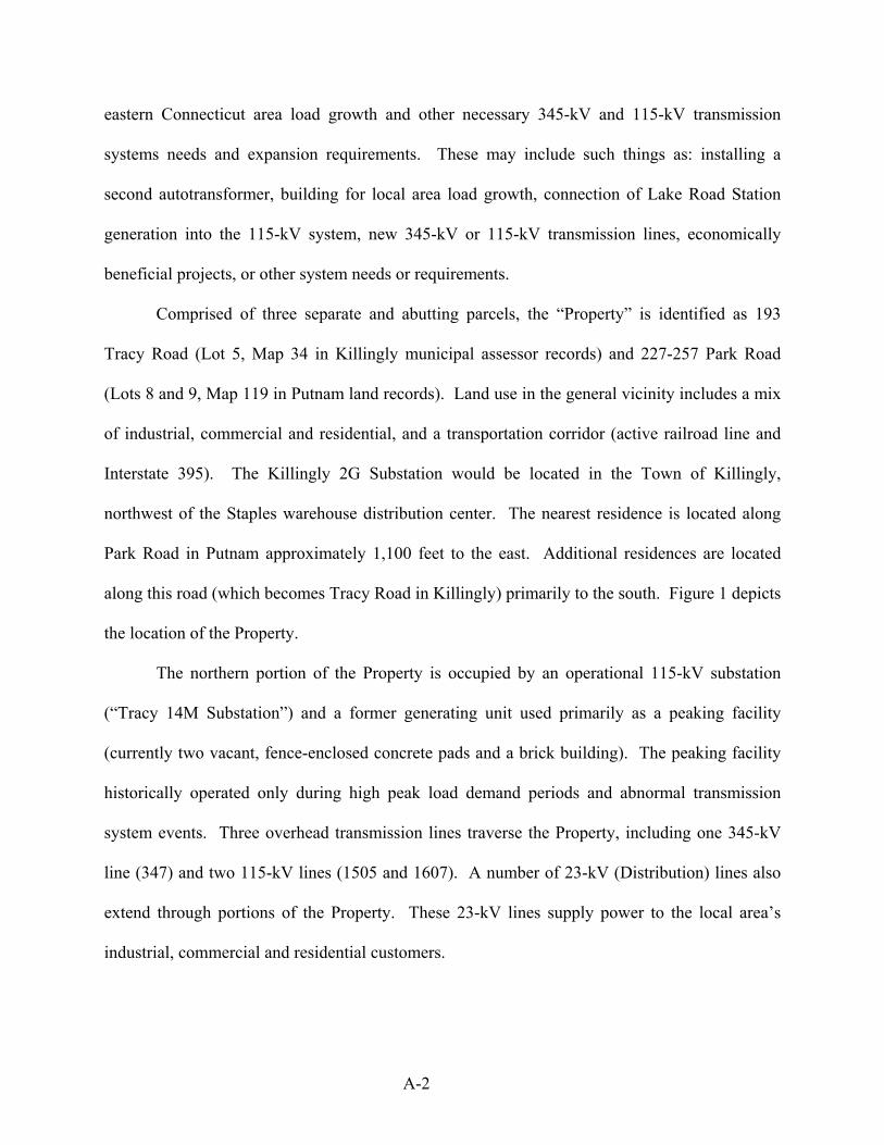
An artist rendering of the Killingly 2G Substation is provided as Figure 2. Technical
specifications and related information are presented in Exhibit 1 (Site Plan Drawings) and
Exhibit 2 (Description of Facility Statement).
F-2
F-3

G. NEED FOR FACILITY
CL&P’s transmission system is an integral part of the bulk power system delivering
power to customers in the northeast region of the United States. In order to maintain integrity of
the bulk power system, it is necessary to ensure adequate transmission and generation sources
are available to meet projected load requirements. As a transmission provider, CL&P must
operate and maintain its system consistent with the reliability standards and criteria developed by
the Northeast Power Coordinating Council (“NPCC”), the New England Power Pool and the
New England Independent System Operator (“NEPOOL” and “ISO-NE,” respectively). These
criteria are established under the purview of the North American Electric Reliability Council
(“NERC”), which establishes the standards for electric power transmission for all of North
America. The criteria set by NPCC and NEPOOL/ISO-NE expressly require transmission
operators to plan, design, test and operate their transmission systems to withstand representative
contingencies in order to provide a reliable transmission network which meets national reliability
standards. If CL&P’s transmission system does not have sufficient capability to serve forecasted
load under the conditions outlined in the NPCC and NEPOOL/ISO-NE criteria, CL&P must plan
for and implement system modifications to address the identified inadequacies.
In this case, CL&P is proposing to install the Killingly 2G Substation to alleviate
transmission-capacity constraints and improve system reliability in the eastern Connecticut
service area (see Figure 3). Northeast Utilities (NU) evaluated the reliability of the existing
eastern Connecticut service area transmission system to withstand various system contingencies
as prescribed by NPCC and NEPOOL/ISO-NE criteria. Based on these criteria, NU’s analytical
results show many normal planning criteria contingencies result in overloaded transmission lines,
G-1

G-2

unacceptable low voltages including the potential of voltage collapse. Additionally, many of
these overloads would result in transmission lines being tripped; they could also result in voltage
collapse if significant load is not shed. Such events could start to occur beginning in 2006.
These conditions are due to a combination of factors, including load growth, limitations in
existing transmission infrastructure, and generator availability. Given these factors, NU
anticipates that problems would continue to emerge and worsen, unless changes to the existing
system configuration are implemented in the near future. CL&P’s Killingly 2G Substation
would alleviate these problems by increasing transmission capacity at a point on the system that
requires reinforcement in order to meet future load requirements in the area.
Two design alternatives were considered for the Killingly 2G Substation: a low profile air
insulated substation (AIS) and a sulfur hexafluoride (SF6) gas insulated substation (GIS).
Several factors were considered in determining the proper design alternative for the Killingly 2G
Substation, including:
• Disturbance of Statutory Facilities
• Existing overhead 345-kV and 115-kV transmission line connections and the 345/115-kV
autotransformer connection requirements
• Maintainability and spare parts availability
• Future expansion capabilities
• Earthwork requirements based on existing topography
• Economic considerations
Considering these factors, CL&P determined the AIS design alternative to be preferable
to GIS. Normally, the costs of constructing GIS can be two to six times that of AIS. In general,
G-3

utilities justify the use of GIS where there are severe weather concerns, contaminated
atmospheres, or location and/or physical constraints. Such limitations do not exist on this
Project.
Exhibit 3, Need Statement for the Proposed Killingly 2G Substation, provides detailed
information regarding the necessity of the Killingly 2G Substation, including a review of the
criteria and standards applicable to the transmission planning process, the methodologies used in
the contingency analysis, a demonstration of need, and studies indicating that the Killingly 2G
Substation would eliminate problems due to the transmission overloads and low voltages
projected to occur beginning in 2006.
G-4

H. EXISTING CONDITIONS
An Existing Conditions Map, depicting current conditions on the Property, its access,
abutting properties, and several key features discussed herein, is provided as Exhibit 4. The
purpose of this section is to describe conditions on the Property as they exist today. A detailed
discussion of the Killingly 2G Substation’s effects on the environment is provided in Section K
of this document.
H.1. Existing Development
CL&P’s Property is located in a mixed industrial, commercial and residential area of
northeast Connecticut. The Property is bound by a truck service facility and a residence/small
business to the north, an active rail line to the west, a Staples distribution facility to the south,
and Park Road (Putnam) and a residential property to the east. Residences exist across Tracy
Road in Killingly and on Park Road in Putnam (Park Road in Putnam becomes Tracy Road in
Killingly). The nearest residence is located approximately 1,100 feet from the proposed
Substation. The I-395 transportation corridor extends south to north approximately 800 feet to
the west of the Property.
H.2. Site Access
A short paved road provides vehicular access to the existing Tracy 14M Substation and
the northern portion of the Property. Vehicular access to the remainder of the Property is via
unpaved roads within the existing utility corridors. These roads can be accessed from the east
via an existing curb cut and a gated entrance off Park Road in Putnam. A secondary entrance
farther south (along Tracy Road) is currently and will remain blocked to vehicles, restricting
unauthorized access from this location.
H-1
H.3. Wetlands and Watercourses
Wetlands located on the Property were delineated in the field by a Certified Professional
Soil Scientist, flagged, and subsequently surveyed and mapped. The limits of the wetlands and
their respective identifiers are shown on the Existing Conditions Map (Exhibit 4). Details of the
investigation can be found in the Wetlands Delineation Report provided in Exhibit 5.
Three wetland systems were identified and are isolated to the northern portion of the
Property within the Town of Putnam. No wetland or watercourse areas are located on the
portions of the Property located in the Town of Killingly.
Wetland C17 is a palustrine hillside seep system containing forested and scrub/shrub
vegetative cover types located in the northeastern corner of the Property. The wetland originates
from a hillside seep system located off the subject Property northeast of Park Road, drains under
Park Road picking up storm water drainage, then enters a forested wetland system located on the
Property along its eastern boundary. An interior intermittent watercourse (IWC-17) drains the
wetland, forming a relatively narrow corridor with bordering wetland habitat as it crosses one of
the unpaved maintenance roads. As the wetland flows in a westerly direction, the vegetation
cover transitions into a scrub/shrub habitat with young saplings before the wetland boundary
terminates with the intermittent watercourse channel that drains the wetland in a southwesterly
direction. This channel flows through an existing culvert associated with the maintenance road
and continues down slope for a few hundred feet before the defined channel banks diminish into
sheet flow.
Wetland 1 is a small disturbed hillside seep, palustrine forested wetland located between
the existing Tracy 14M Substation and the former peaking station. An intermittent watercourse
drains Wetland 1 through a constructed riprap channel, along the northern boundary of the
H-2

existing Tracy 14M Substation, through two culverts under the two access drives entering the
Substation, eventually draining into Wetland 2.
Wetland 2 is a hillside seep, palustrine forested wetland located west of the existing
Tracy 14M Substation. The southern extent of this wetland contains a small palustrine emergent
marsh community, distinguished by its hummock hollow topography, shallow inundation and
dominance of herbaceous vegetation.
H.4. Vegetation and Wildlife
Vegetation on the Property is common to post agricultural early- and mid-successional
growth with areas manipulated by vegetation maintenance activities underlying the existing
overhead electrical transmission lines. The Property contains a variety of upland habitat covers
including low shrub, young pine forest, young mixed forest, mature pine forest, old field, and
developed areas (former generation peaking facility and the existing Tracy 14M Substation), in
addition to the three wetland systems previously described. Detailed descriptions of these
vegetative habitats are provided in the attached Wildlife Habitat Survey (Exhibit 6). The
majority of these habitats have been altered by existing development, ongoing vegetation
maintenance activities, and unauthorized all-terrain vehicle (ATV) trespassing. Numerous trails
have been cut throughout the Property by ATVs causing erosion and habitat alterations in several
areas.
Wildlife habitats associated with the Property were assessed by conducting field
inventories to identify herpetofauna, avian, and mammal species present, taking into account the
habitat conditions present within each resource area. Habitat variables considered in the wildlife
evaluation included the size of the vegetative communities, the plant cover types present, the
degree of habitat disturbance, interspersion of cover types, the abundance and diversity of fruit
H-3

and seed-bearing plants, the size (average diameter) and abundance of tree snags and ground
debris, and surrounding land uses. These vegetative communities were evaluated for their
capacities to provide cover, foraging, and breeding habitats. The results of the field inventories
and assessment of the wildlife conditions indicate that most of the Property contributes moderate
value wildlife habitat. Wildlife habitat values associated with the Property are limited by the
existing development (Tracy 14M Substation, former generation peaking facility and overhead
transmission lines), surrounding industrial development and proximity to the railroad, I-395 and
Park and Tracy Roads.
H.5. Rare, Threatened, and Endangered Species
The Property is not within a listed area as shown on the Connecticut Department of
Environmental Protection (“CTDEP”) Natural Diversity Data Base (“NDDB”) map. A letter
was sent to the CTDEP to confirm that no effects would be anticipated as a result of this Project.
The CTDEP responded that the Property may support suitable habitat for whip-poor-will
(Caprimulgus vociferus) populations, a Connecticut Species of Special Concern. According to
the CTDEP, the whip-poor-will favors open, mixed hardwood forests and are also found in
sapling-stage early successional areas, scrubby immature forests or areas of re-growth following
disturbance in more mature forests. The whip-poor-will lays its eggs on the ground in shady
woods often near the edge of clearings or on relatively dry sandy soils that suppress vegetation
and promote an open canopy. These birds are found in Connecticut only during the nesting
season (late May through June). It is during this period that the species is most susceptible to
disturbances in habitat. No direct observations of whip-poor-will were made during field
inventory activities on the Property, which took place on July 13 and 15, 2004.
H-4

Although not identified by the CTDEP, Brown Thrasher (Toxostoma rufum), another
Connecticut Species of Special Concern, was observed on the subject Property during field
inventory activities. Brown Thrasher is a migratory avian breeder that is fairly common in
suitable habitat, which consists of old fields and brushy pastures. Brown Thrasher prefers open
areas with patches of bare ground on which to feed and nest in suburban and rural areas,
particularly in brushy thickets and woodland edges. Similar habitat exists throughout the
Property and the utility corridor as it extends beyond the Property limits, primarily the result of
CL&P’s habitat management initiatives that have been incorporated into vegetation maintenance
practices.
H.6. Water Supply Areas
Groundwater below and near the Property is classified by the CTDEP as a GA
groundwater area. The GA classification indicates groundwater within the area of existing
private water supply wells or an area with the potential to provide water to public or private
water supply wells. CTDEP presumes that groundwater in such an area is, at a minimum,
suitable for drinking or other domestic uses without treatment.
The closest public water supply wells are part of the Park Road Well Field, located
approximately one mile to the north of the Property, in the Town of Putnam. The Town of
Putnam provides public water service along Park Road and Crystal Water provides public water
along Tracy Road in Killingly.
The Property is within a state designated Preliminary Aquifer Protection Zone.
Connecticut’s Aquifer Protection Program has been developed to protect the water quality of the
state’s highest yielding public water supply wells by establishing Aquifer Protection Areas
(APA) around those wells. The location of these APA is determined through preliminary
H-5

mapping (Level B) and later final mapping (Level A). The mapping is performed by the water
companies who own the wells and is approved by the CTDEP. Land Use Regulations to be
implemented in these areas have been adopted at the state level. However, the Land Use
Regulations that would protect these areas cannot go into effect at the local level until the final
mapping is completed and approved by CTDEP and the municipal program is implemented.
Final mapping has not been completed and the municipal program has not been developed. At
this time, the APA is without special protection under CTDEP regulations. However, substations
and other utility electrical equipment are exempt from APA restrictions.
H.7. Scenic Areas
No State or locally designated scenic roads are located in the vicinity of the Property. In
addition, there are no designated scenic areas in the vicinity. The nearest designated scenic road
to the Property is an approximate four-mile long portion of Route 97 (from Route 44 to Route
169) that is located nearly four miles away.
H.8. Historic and Archaeological Resources
Analysis of the history of the Property was conducted by synthesizing background data
related to prehistoric use of the area, historic occupation of the region, and the natural setting of
the area encompassing the proposed Project items. Preliminary results identified one potential
archaeological site and one potential historic standing structure on the Property.
The archaeological site is located in the southern portion of the Property, within and
immediately adjacent to the existing overhead transmission line corridor. Subsurface testing of
the archaeological site resulted in collection of two historic period and 14 prehistoric artifacts,
75% of which were recovered either at the surface or from disturbed soil contexts (i.e., within the
H-6

plow zone). Excavation of numerous, additional shovel tests throughout the archaeological site
area did not reveal any evidence of cultural features, substantial numbers of artifacts, or
temporally diagnostic materials.
The standing structure (associated with the former peaking station) represents early- to
mid-twentieth century construction. The building was constructed with a concrete foundation,
brick walls, large windows encased in metal frames, copper gutters, and roof clad in composite
shingles. The building, which also contains large metal doors and a loading dock area, was once
used as the main substation building for the local electrical utilities.
The activities and results of the survey are documented in the Management Summary for
Phase I Cultural Resources Reconnaissance Survey of the Proposed Killingly 2G Substation
Project, Killingly and Putnam, Connecticut, a copy of which is included in Exhibit 7.
H.9. Natural Resources
According to the Bedrock Geological Map of Connecticut compiled by John Rogers in
1985, bedrock geology underlying the general vicinity consists of fine-grained, well-layered
schist and granofels and/or gray to dark-gray, medium-grained, well-layered gneiss. A bedrock
core collected in the southern portion of the Property revealed that this area is underlain by the
gneiss formation. Depth to bedrock at this location was measured at approximately 16 feet
below existing grade.
According to the Surficial Materials Map of Connecticut dated 1992, surficial geology of
the eastern portion of the Property consists of thin glacial till (generally less than 10 to 15 feet
thick) while sand and gravel overlying sand and fines deposits occupy the western portion of the
Property. Soils derived from these parent materials were generally field confirmed by a
professional soil scientist at the subject Property.
H-7

H.10. Floodplain Areas
According to Flood Insurance Rate Map, Community-Panel Numbers 090136 0002 B and
090194 0004 B, January 3, 1985 and October 18, 1988, there are no flood hazard areas on the
subject Property. The nearest floodplain is associated with the Quinebaug River located
approximately 1,000 feet west of the Property across I-395. The 100-year base flood elevation in
this location is approximately elevation 220 feet above mean sea level (AMSL). The lowest
elevation on the subject Property is approximately 242 feet ALMS.
H.11. Recreational Areas
There are no recreational areas proximate to the Property. The nearest recreational area
to the Property is the Airline State Park Trail (Northern Section), which extends generally in a
north to south direction approximately 1.5 miles to the east. Quaddick State Forest is located
approximately two miles to the northeast of the Property.
H.12. Seismic Areas
There are no seismic areas on the Property or in its immediate vicinity. A mapped fault
zone, know as the Lake Char Fault, is located approximately 0.75 mile to the east.
H.13. Noise
A noise monitoring program was conducted to determine existing sound levels at the
Property. Noise monitoring was conducted at two locations, including the southern Property line
and the nearest residential area to the east along Tracy Road. The noise measurements were
conducted during the nighttime period (10:00 p.m. to 7:00 a.m.) to represent the lowest
H-8

background sound levels that occur near the Property. The Property is located in a mixed
industrial, commercial and residential area, east of Park and Tracy Roads, west of an active
railroad line, and about 800 feet from Interstate 395. The sound measurements included typical
nighttime sources, such as rooftop mechanical equipment, building operations, and vehicle
traffic.
The results of the noise monitoring program indicate that existing noise levels at the two
receptor locations monitored are below the CTDEP’s noise control regulations (Regulations of
Connecticut State Agencies RCSA, Title 22a, Section 22a-69-1 to 22a-69-7.4). A copy of the
Noise Impact Analysis is provided in Exhibit 8.
H.14. Lighting
The existing Tracy 14M Substation is not normally lit. However, it does have lighting
capabilities throughout its yard area to allow work at night under emergency conditions.
H.15. Other Statutory Facilities
There are no other Statutory Facilities in the proximity of the Property. Figure 4,
Surrounding Features, depicts the nearest locations of Statutory Facilities, including those
discussed above and the following:
• Settled areas
• Schools and daycare centers (schools: over 3 miles to south and northwest - daycare: over
one mile to the west)
• Hospitals (Health Care center nearly one mile east; Hospital 2 miles northeast)
• Group homes (2 miles northwest)
• Hunting or wildlife management areas (none within 3 miles of the Property)
• There are no tidal wetlands or costal zone management areas involved
H-9

H-10

I. SITE JUSTIFICATION
The Property was identified and purchased as a viable future substation site in 1968 in
anticipation of area load growth and potential long term limitations of the existing Tracy 14M
Substation. It is located within an area zoned for industrial uses in the Towns of Killingly and
Putnam. CL&P evaluated this Property and other sites to determine the best location for the
Killingly 2G Substation. Based on this review and evaluation the Property was deemed the most
viable for this development. The following major criteria were considered:
• Proximity to the customer load
• Proximity to the existing overhead 345-kV transmission line east of Lake Road Substation
• Proximity to the existing overhead 115-kV transmission lines or Tracy 14M Substation
• Environmental effects
• Zoning and present land use
• Earthwork requirements based on existing topography
Four locations were identified for further evaluation, including three on the Property and
one on an adjacent, separate parcel to the east. These locations are discussed below and depicted
on Figure 5.
Location 1 (Proposed Killingly 2G Substation Site; the “Site”)
• Close proximity to the customer load.
• Very close proximity to the existing 345-kV overhead transmission 347 line and
technically simple to connect.
• Very close proximity to the existing 115-kV overhead transmission 1505 and 1607 lines
and technically simple to connect.
I-1

I-2

Location 1 (Proposed Killingly 2G Substation Site; the “Site”) (con’t)
• Minimal environmental effects.
• Minimal visual impact to residents; however the Killingly 2G Substation would be visible
to motorists traveling on I-395.
• No zoning or land use changes are required.
• Minor to moderate earthwork required.
The Site is located within close proximity (700+ feet) to the existing Tracy 14M
Substation. The Site would allow the Killingly 2G Substation to easily connect into the existing
345-kV and 115-kV overhead transmission lines via a simple loop through design. The
connections to these lines can be made without any changes to the line profile beyond the
Property limits and without any modifications to the existing utility transmission corridor limits.
The Killingly 2G Substation can be constructed on the Site without any effects to the existing
inland wetlands. There would be minimal visibility to the existing residents; however, the
Killingly 2G Substation would be visible to motorists traveling on I-395. The Killingly 2G
Substation would fit within the existing Property limits, and would also fit within the nominal
280’ elevation topographic contour, thus requiring minimal disturbance to the existing
topography. It also would not require any zoning or land use changes.
Location 2 (South of Park Road in the area of the former peaking station)
• Close proximity to the customer load.
• Close proximity (within approximately 500 feet) to the existing 345-kV overhead
transmission 347 line, however, connection to the 347 line would be complicated by the
need to underground a portion of the connection.
I-3

• Close proximity (1,000 ft.) to the existing 115-kV 1505 and 1607 lines, however, new
lines and associated transmission structures and equipment would be required to
accommodate this connection.
• The Killingly 2G Substation would have environmental effects by encroaching into
existing wetlands and create a much greater visual impact.
• No zoning and land use changes are required.
• Moderate to heavy earthwork is required.
This location lies approximately 150 feet to the northeast of the existing Tracy 14M
Substation and would allow the proposed Substation to connect into the existing 345-kV
overhead transmission 347 line. However, it would require a short 345-kV overhead and
underground connection along with the construction of two new 115-kV lines to allow
connection into the existing Tracy 14M Substation. This location does not have the necessary
area available for the Facility being considered. Even if this location was acceptable, it would
still require significant construction and extension to the existing Tracy 14M Substation. The
connection could be made without any changes to the line profile off the Property limits and
without any modifications to the existing utility corridor limits. This location would encroach
into existing inland wetlands if constructed and would also create a greater visual impact to the
existing residential neighbors and motorists on Park Road. This location would not require any
zoning or land use changes.
I-4

Location 3 (South of Existing Tracy 14M Substation)
• Very close proximity to the customer load.
• Close proximity (approximately 650 feet) to the existing 345-kV transmission 347 line,
however, connection to this line would be more complicated and less reliable due to the
need to underground a portion of the connection.
• Very close proximity to the existing 115-kV.
• The Killingly 2G Substation would have environmental effects, as the connection to the
existing 345-kV overhead transmission 347 line would encroach on existing inland
wetlands, and its construction would also affect existing storm water drainage.
• It would have minor visual impact to residents.
• No zoning or land use changes are required.
• Extensive earthwork and fill are required.
This location lies immediately south of the existing Tracy 14M Substation and would
allow the Killingly 2G Substation to connect into the existing 345-kV overhead transmission 347
line and both the existing 115-kV overhead transmission (1505 and 1607) lines located on the
Property. However, the connection to the 345-kV would be more complicated and less reliable
due to the need to underground a portion of the connection. All 345-kV and 115-kV line
connections could be made without any changes to the line profile off the Property limits and
without any modifications to the existing utility corridor limits. The Killingly 2G Substation
would have significant environmental effects at this location. It would encroach upon at least
two of the existing inland wetlands and would require extensive filling and grading throughout
the area to level the existing topographic contours to accommodate the Facility. This location
I-5

would have a minor visual impact to existing residential neighbors. It would not require any
zoning or land use changes.
Location 4 (North of Park Road – Map 119, Lots 8 and 9)
• Close proximity to the customer load.
• Very close proximity to the existing 345-kV overhead transmission 347 line.
• Close proximity (1,500 ft.) to the existing 115-kV lines and substation, however, new
lines and associated structures and equipment would be required.
• This location would have environmental significant effects, requiring extensive
vegetation and tree removal. In addition, development on these parcels would also
encroach upon the existing inland wetlands on the subject Property across the street.
• It would have a significant visual impact on residents and anyone traveling along Park
and Tracy Roads.
• It would require zoning and land use changes.
• Extensive earthwork and fill would be required.
This 20.8-acre property is also owned by CL&P, is reasonably close to the existing Tracy
14M Substation and would allow the Killingly 2G Substation to connect into the existing 345-kV
overhead transmission 347 line. However, this location would require two new 115-kV
overhead transmission lines to be constructed over Park Road in order to connect to the existing
115-kV transmission system. This location would also have a significant effect on the
environment because the Killingly 2G Substation would require extensive tree and vegetative
clearing. It would also encroach on the existing inland wetland on CL&P’s adjacent Property
across Park Road to the west. The Killingly 2G Substation would fit within the existing Property
I-6

limits, but would require extensive grading and fill to level the existing topographic contours to
accommodate the Killingly 2G Substation. This location would have a significant visual impact
to both the existing residential neighbors and to those traveling along Park Road due to the
location of the proposed Substation and the construction of the two new 115-kV overhead
transmission lines and associated structures that would be required. Unlike the three locations
previously discussed, this location is not in an area zoned for industrial use.
I-7

J. SAFETY AND RELIABILITY INFORMATION
The Killingly 2G Substation would be designed to continue to serve the customer load
even during a system or equipment failure. This would be achieved by incorporating “loop
through” design configurations for the existing 345-kV and 115-kV overhead transmission lines,
autotransformer protection, and redundant automatic protective relaying equipment. The 345-kV
portion of the Substation would include one circuit breaker to facilitate the “loop through” design
configuration. In the event of a 345-kV line fault or failure of the autotransformer, the circuit
breaker would operate to isolate the faulted equipment.
The 115-kV portion of the Substation would include eight circuit breakers in a standard
breaker and one-half configuration. A pair of circuit breakers would be used to protect each of
the incoming 115-kV overhead transmission lines (1505 and 1607) and each of the outgoing 115-
kV overhead transmission lines (1405 and 1621). In the event of a 1505 or 1607 line fault, the
respective pair of circuit breakers would isolate the faulted 115-kV line, thus preserving one of
the two incoming 115-kV lines which connect to the Killingly 2G Substation. The same
situation would occur for a fault on the 1405 or 1621 line, thus preserving one of the two
outgoing 115-kV lines which supply the Tracy 14M Substation. With the installation of the
autotransformer, as long as one incoming (1505 or 1607) and one outgoing (1405 or 1621) 115-
kV line remains in service, CL&P can maintain system reliability to the eastern Connecticut
service area.
Protective relaying equipment would be provided to automatically detect abnormal
system conditions (e.g., a faulted overhead transmission line) and would send a protective trip
signal to the respective circuit breaker(s) to isolate the faulted section of the transmission system.
The protective relaying schemes would include fully redundant primary and backup equipment
J-1

so that a failure of one scheme does not require the portion of the transmission system being
monitored by the protective relaying equipment to be removed from service. The protective
relaying and associated equipment, along with a System Control and Data Acquisition (SCADA)
system for remote control and equipment monitoring by the Convex System Operator, would be
housed in the weatherproof, environmentally-controlled electrical enclosure.
The electrical control enclosure would have fire extinguishers installed along with smoke
and heat detectors and would be monitored from a remote location. Other various devices would
constantly monitor the Substation equipment to alert CL&P of any abnormal or emergency
situations. The facility would be fenced with a seven foot high chain link fence topped with
barbed wire to control unauthorized entry.
The 345/115-kV autotransformer would have fire walls installed in between the inside
phases to prevent a fire in one single phase unit from cascading into an adjacent single phase
unit. Also, each phase of the autotransformer is built with a PVC containment sump to control
and contain any oil release.
J-2

K. EFFECTS ON THE ENVIRONMENT
The development of the proposed Killingly 2G Substation in the southern portion of the
Property would not have any significant, long-term adverse effects on the existing environment
and ecology, nor would it impact the scenic, historic and recreational values of the vicinity. A
Proposed Conditions Map is included as Exhibit 9.
K.1. Public Health and Safety
The Killingly 2G Substation would be designed to all applicable CL&P, Industry, State,
and Local Codes and Standards and would not pose any safety or health hazards to any persons
or Property. The Killingly 2G Substation does not have any rotating machinery, does not
consume any raw materials, does not produce any by-products and would be un-manned during
normal operating conditions.
K.2. Local, State And Federal Land Use Plans
The Killingly 2G Substation Project is consistent with local, state, and federal land use
plans. Local land use application processes do not specifically apply to this Project. However,
the Project has been designed to meet the intent of local land use regulations. According to the
Zoning Regulations for the Towns of Putnam and Killingly, the Property lies within an area
zoned for Industrial uses. The Town of Killingly’s Plan of Development (dated April 1987)
identifies the location of the Property as being within a secondary recharge area (a land area
adjacent to the primary recharge area from which groundwater moves down-gradient into an
aquifer). The Town of Putnam is in the process of developing a State Plan of Conservation and
Development map, which is not at a stage where it is available for consideration at this time.
K-1

K.3. Existing And Future Development
The Killingly 2G Substation would have the effect of supporting existing development by
providing improved electrical service to the area and encouraging additional development
through enhanced reliability and the capacity to serve additional future load.
K.4. Roads
An existing entrance along Park Road would be upgraded and incorporated into a new
1,200+ foot long drive that would extend southwestward to the Site. During construction, the
access road would be stabilized with stone to prevent tracking of mud onto local streets. Upon
completion of the Facility, the road would be paved. This would be an unmanned Facility and
therefore, after construction is completed, approximately three to four vehicular trips per month
to the Property are anticipated.
K.5. Wetlands
Three wetlands were identified on the Property, all located within the Town of Putnam.
Development of the Killingly 2G Substation would not directly impact any wetlands. The Town
of Putnam Inland Wetlands and Watercourses Commission does not regulate a specific upland
review area but evaluates each development on a case-by-case basis. The Commission appears
to have a policy of a 50-foot upland review area to wetlands and watercourses. This policy will
be addressed with the town during the MCF process. Limited site work associated with the
proposed access drive would occur within the 50-foot upland review area, however, no work is
proposed that would directly impact wetlands. The orientation of the existing access drive that
crosses Intermittent Watercourse C17 (IWC C17) would be altered to improve the roadway
geometry. This would result in an upgrade of the existing culvert and temporary disturbance of
K-2

approximately 20 linear feet of IWC C17. The existing culvert section of IWC C17 would be
restored to natural channel characteristics, thereby resulting in minimal cumulative disturbance
to the intermittent watercourse. Disturbances near the wetland are necessary to improve the
existing access drive and would include minor grade adjustments and realignment. The
disturbed area near the wetland would be dressed with topsoil and seeded with a New England
conservation/wildlife mix, providing a permanent cover of grasses, forbs, wildflowers and
legumes to provide both erosion control and enhanced wildlife habitat value.
K.6. Wildlife and Vegetation
The Killingly 2G Substation Site would occupy what is currently a mix of low shrub,
young pine forest, mature pine forest, and old field habitats located in the southwestern portion
of the Property. The proposed access drive would generally follow the route of an existing
maintenance road starting off Park Road and extending primarily through old field habitat. The
Killingly 2G Substation and access drive development areas are located within and in close
proximity to existing utility corridors occupied by overhead electrical transmission lines. This
corridor generally extends off the Property in a northeast to southwest direction for numerous
miles. Therefore, the proposed Project is not anticipated to have a significant impact on wildlife
due to existing development and the Site’s immediate proximity to similar habitats that would
allow for natural relocation of potential wildlife from the construction zone. Further, once
operable, the Killingly 2G Substation would be un-manned.
To provide additional value for wildlife, vegetative screening planned for the southeast
and northeast sides of the Facility would consist of coniferous tree species and re-vegetation
along its northern side would incorporate native shrubs. Additional slope stabilization efforts
K-3

further north of the Killingly 2G Substation, where excessive soil erosion is currently taking
place, would also utilize native shrubs, further enhancing the Property’s potential habitat value.
K.6.1. Rare, Threatened, and Endangered Species
Brown Thrasher (Toxostoma rufum), a Connecticut Species of Special Concern, was
identified on the subject Property during the wildlife habitat survey. Although the Killingly 2G
Substation would occupy potential habitat for Brown Thrasher, similar habitat immediately
adjoins the proposed development area allowing for easy relocation of potentially displaced
individuals. Therefore, the proposed development would not adversely affect Brown Thrasher
habitat. Similar habitat preferred by another Connecticut Species of Special Concern, the whip-
poor-will, also exists on other portions of the Property and extends beyond its boundary along
the overhead transmission lines corridors.
Conversations with Jenny Dickson, Wildlife Biologist with the CTDEP, indicated that
future construction activities at the Property could incorporate mitigation measures that would
enhance surrounding habitat to support the two Species of Special Concern. Suggested
mitigation measures will be included in the CTDEP’s letter of “no effect”, which will be
provided as Exhibit 10. It is CL&P’s intent to continue to provide suitable habitat for these
species.
K.7. Water Supply Areas
Construction and operation of the proposed Killingly 2G Substation would not impact
water supply areas. The closest public water supply wells are located approximately one mile
away. The Property is situated within a state designated Preliminary Aquifer Protection Zone,
which has likely been established to protect those wells. Currently, no specific restrictions are
K-4

imposed on development in this Zone. Transformers at the Killingly 2G Substation would use
insulating oil fluids; however, the equipment would have secondary containment and accidental
spill prevention provisions in place. Based on these design considerations and the physical
distance of the water supply wells to the Killingly 2G Substation, the project would have no
adverse environmental effect on the aquifer.
The Town of Putnam provides public water service along Park Road in Putnam and
Crystal Water provides water service along Tracy Road in Killingly. CL&P intends to bring
water service underground into the Facility from Park Road to the east, generally following the
proposed access road route.
K.8. Historic And Archaeological Resources
Initial coordination with the Deputy State Historic Preservation Officer (SHPO) resulted
in a recommendation to conduct a Phase I Cultural Resources Reconnaissance Survey of the
Property. This recommendation was based on the Deputy SHPO’s opinion that portions of the
Property may possess moderate to high sensitivity for prehistoric and historic archaeological
resources. Heritage Consultants, LLC performed the survey and produced the required technical
report, consistent with the Environmental Review Primer for Connecticut’s Archaeological
Resources.
The archaeological site located in the southern portion of the Property falls within the
eastern footprint of the Killingly 2G Substation. Based on results of the field survey, it was
determined that both the historic and prehistoric components of the archaeological site retained
little, if any, research potential. As a result, components of the archaeological site were assessed
as not significant, applying the National Register of Historic Places criteria for evaluation (36
CFR 60.4 [a-d]). No additional investigation of this area was recommended.
K-5

Similarly, the standing structure associated with the former peaking station is not
considered significant, applying the National Register criteria (36 CFR 60.4 [a-d]). Its setting
would not be impacted adversely by the proposed Project and no additional recording of this
standing structure was recommended.
Detailed information regarding the Phase I Cultural Resources Reconnaissance Survey is
contained in a Management Summary for Phase I Cultural Resources Reconnaissance Survey of
the Proposed Killingly 2G Substation Project, Killingly and Putnam, Connecticut (see Exhibit
7), which was submitted for review to the SHPO at the State of Connecticut Commission on
Culture and Tourism, Historic Preservation and Museum Division. The results of the survey
indicate that no significant impacts would occur to historic or cultural resources as a result of the
proposed Killingly 2G Substation and its associated access road. After review of the
Management Summary report, the SHPO concurred with its findings and issued a letter of “no
effect”. A copy of the SHPO’s determination letter is included in (Exhibit 11).
K.9. Noise
A noise analysis was conducted to evaluate potential noise impacts associated with the
installation of the Killingly 2G Substation. The noise analysis evaluated both existing and future
sound levels that would occur at the Property. The existing condition sound levels were
determined by a noise monitoring program. The Killingly 2G Substation’s sound levels were
calculated using manufacturer’s sound data and the principles of acoustical propagation of sound
over distance, incorporating combined existing noise conditions and sound levels.
Noise monitoring was conducted at two locations during the nighttime period; at the
southern Property line and the nearest residential area to the Proposed Killingly 2G Substation
east of Tracy Road. These monitoring locations were selected because they represent the
K-6

locations of maximum potential impact. Anticipated future sound levels were compared to the
CTDEP noise control regulations (Regulations of Connecticut State Agencies RCSA, Title 22a,
Section 22a-69-1 to 22a-69-7.4). Under CTDEP regulations, the new Killingly 2G Substation is
allowed to have a noise level of up to 51 dBA at night time and 61 dBA during the day time at its
Property line. The results of the noise analysis demonstrate that development and operation of
the Killingly 2G Substation would not violate the applicable nighttime and daytime noise control
standards and there is no significant increase over existing noise level (See Exhibit 8, Noise
Impact Analysis). In order to minimize the effect on noise, CL&P is proposing to install a
special low noise design autotransformer for this project.
K.10 Floodplains
The Killingly 2G Substation would be constructed at an elevation of approximately 280
feet AMSL, well above the Quinebaug River’s 100-year base flood elevation of 220 feet AMSL.
The Quinebaug River is located approximately 1,000 feet west of the Property across I-395.
K.11. Lighting
The Killingly 2G Substation yard would not normally be lit at night, but lighting
capability would exist throughout the yard to allow work at night under abnormal or emergency
conditions. The building security and safety light fixtures needed for occasional visits to the
Facility would be full cutoff or recessed luminaries. These would minimize degradation of the
night-time visual environment while preventing glare, light trespass, or light pollution.
K-7

K.12. Natural Resources
Soils identified within the proposed Substation footprint are classified as Merrimac sandy
loam and Hinckley gravelly sandy loam. Merrimac is a somewhat excessively drained,
moderately coarse textured, friable glacial till soil. Hinckley is an excessively drained, gravelly,
coarse textured, loose glacial fluvial (outwash) soil. Soils identified along the proposed access
drive route are classified as Charlton-Chatfield fine sandy loam, Merrimac and Hickley.
Charlton-Chatfield are deep and moderately deep to bedrock, well drained and somewhat
excessively drained, moderately coarse textured, friable glacial till soils. This field classification
is generally consistent with published information for the area (Soil Survey of Windham County,
Connecticut, USDA SCS, November 1970 and updated digital soil information available from
the Natural Resources Conservation Service). Minor to moderate earthwork is required to
accommodate the Killingly 2G Substation at the Site.
K-8

L. MITIGATION MEASURES
After construction is complete, the Killingly 2G Substation would have no permanent
adverse effects on the environment. The 345/115-kV autotransformer within the Killingly 2G
Substation would contain insulating oil. The transformer would have secondary containment
consisting of an underlying and surrounding polyvinyl-lined sump. The systems would be
designed to hold 110% of the transformers’ capacities.
Construction activities associated with the proposed access road would have no impact to
the existing wetlands. A 20 foot wide, paved access road would be constructed with
approximately eight inches of crushed stone base, including a final surface of two inches of
asphalt concrete pavement (post-construction). Construction of the access road includes work
within the 50-foot upland review area; however, no work within wetlands would occur.
Disturbances near the wetland are necessary to improve the existing access drive and would
include minor grade adjustments and realignment. CL&P would establish and maintain effective
erosion and sediment controls, in conformance with the 2002 Connecticut Guidelines for Soil
Erosion and Sediment Control, during construction to avoid the potential for impacts. Disturbed
areas near the wetland would be dressed with topsoil and seeded with a New England
conservation/wildlife mix, providing a permanent cover of grasses, forbs, wildflowers and
legumes to provide both erosion control and wildlife habitat value. The existing culvert section
of Intermittent Water Course C17 would be upgraded and restored to natural channel
characteristics, thereby resulting in minimal cumulative disturbance to this intermittent
watercourse.
L-1

Grading for the Killingly 2G Substation yard would provide surface runoff. A minimum
slope of 1/100 within the Facility’s foot print would control the storm water runoff and provide
adequate drainage. The Site drainage facilities would be designed for the flow resulting from a
100-year, 24-hour rainfall. Hay bales and/or geotextile silt fence (GSF) would be installed and
maintained to the limits of the grading contours to temporarily control sedimentation runoff until
permanent and effective erosion controls are established after construction is completed. All
disturbed areas and stockpiled materials would be provided with a GSF or equivalent erosion
control measures.
The proposed Substation yard would be graded to drain away from the northeast side of
the Facility, ultimately discharging into an existing depression at the toe of the slope in the west-
central portion of the Property. Because the yard would be covered with a pervious surface of
six inches of crushed trap rock, concentrated flows are not expected. All disturbed areas would
be covered with either riprap (for slopes steeper than 2:1) or topsoil and seeded. Several areas
would also be planted with native shrubs and/or trees. A detailed landscape plan will be
provided during the CSC Application process as part of the development and management plan.
Preservation of wildlife habitat would be accomplished primarily by preventing impacts
to the wetland by erosion and sediment control during and after construction. Any disturbed
areas on embankments would be planted with native shrubs that provide food and cover for
wildlife. In addition to the seeding and shrub plantings, plantings of evergreen trees are planned
for the northeastern and southeastern portions of the Site to provide screening and enhanced
wildlife value. A Landscape Plan would be prepared to provide details for erosion control,
screening and wildlife enhancement plantings as part of the CSC application process.
L-2

The proposed Site location and configuration provides sufficient setback from the road to
allow a natural tree buffer to be maintained. Existing wooded buffers on the eastern, western and
northern portions of the Property would be retained for screening. The nearest residence to the
Site is located approximately 1,100 feet to the east; this home does not have direct views to the
proposed Site because of an established vegetative buffer between it and the Property. Enhanced
screening would be proposed along the southern portion of the Killingly 2G Substation. Since
homes to the north and east are well screened from the Site by existing vegetation and
topography that are to remain unchanged, no planting of vegetation is needed. The Landscape
Plan (to be prepared in the future) would incorporate comments and suggestions resulting from
consultation with the municipalities, neighbors and other interested parties.
L-3

M. HEALTH AND SAFETY
M.1 Electric And Magnetic Fields
The strength of an electric field at a given location depends on two factors — the level of
voltage applied to the conductor (in this case, the transmission lines) and the distance from it.
Magnetic fields are produced where electric current is present. The strength of a magnetic field
at a given location depends on the level of current flowing in the conductor or wire and the
distance from it.
At and beyond the Property boundaries, the dominant source of electric and magnetic
field (EMF) levels before and after activation of the Killingly 2G Substation are and would be
the transmission lines. The Substation itself would not significantly add to the existing field
levels because the lines are the dominant source of EMF on the Property. Three transmission
lines currently cross the Property: two 115-kV lines (lines 1505 and 1607) and one 345-kV line
(line 347). No additional lines would be constructed in association with the Killingly 2G
Substation development.
An EMF analysis was conducted at the Property to evaluate the effect that construction of
the Killingly 2G Substation would have on EMF emissions. Given that the voltages on the lines
would remain constant (i.e., the development of the Killingly 2G Substation would not alter the
current voltages), the electric field at the Property boundaries would remain essentially
unchanged. The maximum electric and magnetic fields along the Property boundaries are
generated by the 345-kV line. Further, the maximum fields along the 345-kV line are at its
westernmost portion (adjacent to the railroad and undeveloped land). Projected line loads after
activation of the Killingly 2G Substation show a reduction in load along the western portion of
the 345-kV line. This would result in a reduction of the magnetic fields along the southern
Property boundary near the Staples building, the nearest neighbor. Projected line loadings along
M-1

the eastern portion of the 345-kV line show a marginal increase during peak load periods and no
increase during normal load periods. Therefore, magnetic fields along the eastern portion of this
line would remain essentially the same as presently exist.
Projected loadings on the 115-kV lines show an increase from present current levels. The
115-kV lines are located closer to the center of the Property. Considering these factors, the
dominant source of magnetic fields on the Property would continue to be the 345-kV line.
Results of the EMF analysis reveal the following:
• The Substation itself would not significantly add to the existing field levels because the
lines are the dominant source of EMFs
• Electric fields remain essentially unchanged because they are dependant on voltages on
the transmission lines (that would not change)
• There would be a reduction in some magnetic field levels because the line loads are
decreased along portions of the 345-kV line
Even with project increased loadings on the 115-kV lines, magnetic fields beyond the
transmission corridors are consistent with established guidelines as outlined in the EMF Analysis
Report, which is provided as Exhibit 12. To the extent applicable, CL&P will adhere to the
Connecticut Siting Council’s Electric and Magnetic Field Best Management Practices.
M.2 Site Security
A seven foot high chain link fence with one foot of barbed wire (consisting of three
separate strands) on top would surround the entire perimeter of the Killingly 2G Substation yard.
A remotely monitored camera security system would be installed within the Killingly 2G
Substation to provide additional security. The access road would be gated and locked at its
entrance along Park Road.
M-2

N. A SCHEDULE OF THE PROPOSED PROGRAM FOR CONSTRUCTION,
TESTING, AND OPERATION
Once constructed the Killingly 2G Substation would be an unmanned Facility and would
operate on a 24-hour basis. Facility equipment would be monitored remotely, which would
minimize the number of maintenance trips to a few times per month.
Construction activities associated with the Facility are expected to occur over an
approximate 18 month period. The proposed construction schedule for the Killingly 2G
Substation is attached as Exhibit 13.
N-1

LIST OF EXHIBITS
1. Site Plans
2. Description of Facility
3. Need Statement
4. Existing Conditions Map
5. Wetlands Report
6. Wildlife Habitat Survey
7. Archaeological Survey
8. Noise Analysis
9. Proposed Conditions Map
10. CTDEP NDDB Correspondence
11. SHPO Letter
12. EMF Analysis Report
13. Project Schedule
Exhibits-I

GENERAL GLOSSARY OF TERMS (Not all terms are used in this document) 115-kV: 115 kilovolts or 115,000 volts. 345-kV: 345 kilovolts or 345,000 volts. AC: (alternating current) An electric current which reverses its direction of flow periodically.
(In the United States this occurs 60 times a second-60 cycles or 60 Hertz.) This is the type of current supplied to homes and business.
Ampere (Amp): A unit measure for the flow (current) of electricity. A typical home service
capability (i.e., size) is 100 amps; 200 amps are required for homes with electric heat. Arrester: Protects lines, transformers and equipment from lightning and other voltage surges by
carrying the charge to ground. Arresters serve the same purpose on a line as a safety valve on a steam boiler.
Bundle: (circuit) Two or more parallel 3-conductor circuits joined together to operate as one
single circuit. Bundle: (conductor) Two or more phase conductors or cables joined together to operate as a
single phase. Cable: A fully insulated conductor usually installed underground but in some circumstances can
be installed overhead. CTDEP: Connecticut Department of Environmental Protection. CELT: NEPOOL, Annual Capacity, Energy, Load and Transmission report. CGS: Connecticut General Statutes. Circuit: A system of conductors (three conductors or three bundles of conductors) through
which an electrical current is intended to flow and which may be supported above ground by transmission structures or placed underground.
Circuit Breaker: A switch that automatically disconnects power to the circuit in the event of a
fault condition. Located in substations. Performs the same function as a circuit breaker in a home.
CL&P: The Connecticut Light & Power Company. CMEEC: Connecticut Municipal Electric Energy Cooperative, Inc. Conductor: A metallic wire busbar, rod , tube or cable which serves as a path for electric flow.
Glossary-II

Conduit: Pipes, usually PVC plastic, typically encased in concrete, for underground power
cables. Conversion: Change made to an existing transmission line for use at a higher voltage,
sometimes requiring the installation of more insulators. (Lines are sometimes pre-built for future operation at the higher voltage.)
CSC: Connecticut Siting Council. Convex: Connecticut Valley Exchange. dBA: Decibel, on the A-weighted scale. DC: (direct current): Electricity that flows continuously in one direction. A battery produces
DC power. Demand: The total amount of electricity required at any given time by an electric supplier’s
customers. Distribution: Line, system. The facilities that transport electrical energy from the transmission
system to the customer. D&M Plan: Development & Management Plan. DPUC: (Connecticut) Department of Public Utility Control. Duct: Pipe or tubular runway for underground power cables (see also Conduit). Duct Bank: A group of ducts or conduit usually encased in concrete in a trench. Electric Field: Result of voltages applied to electrical conductors and equipment. Electric Transmission: The facilities (69-kV+) that transport electrical energy from generating
plants to distribution substations. EMF: Electric and magnetic fields. Fault: A failure or interruption in an electrical circuit (short circuit). FEMA: Federal Emergency Management Agency. Fiber Optic Shield Wire (FOSW): See Lightning Shield Wire G: Gauss; 1G = 1000 mG (milligauss); the unit of measure for magnetic fields.
Glossary-III

GIL: Gas Insulated Transmission using sulfur hexaflouride (SF6). GIS: Gas insulated substation. Glacial till: These deposits are predominantly nonsorted, nonstratified sediment and are
deposited directly by glaciers. These deposits consist of boulders, gravel, sand silt, and clay mixed in various proportions.
Gneiss: Light and dark, medium- to coarse-grained metamorphic rock characterized by
compositional banding of light and dark minerals, typically composed of quartz, feldspar and various amount of dark minerals.
Granofels: Light to dark, medium- to coarse-grained, massively to poorly layered metamorphic
rock composed primarily of quartz and feldspar; lacking the compositional banding of gneiss.
Ground Wire: Cable/wire used to connect wires and metallic structure parts to the earth.
Sometimes used to describe the lightning shield wire. H-frame Structure: A wood or steel structure constructed of two upright poles with a
horizontal cross-arm and bracings. Hz: Hertz, a measure of frequency; one cycle/second. ISO: Independent System Operator. ISO-NE: ISO New England, Inc. New England’s independent system operator. kcmil: 1000 circular mils, approximately 0.0008 sq. in. kV: kilovolt, equals 1000 volts. kV/m: Electric field measurement (kilovolts/meter). Lattice-type Structure: Transmission or substation structure constructed of lightweight steel
members. Lightning Shield Wire: Electric cable intended to prevent lightning from striking transmission
circuit conductors. May contain glass fibers for communication use, “Fiber Optic Shield Wire”, or “FOSW”.
Line: A series of overhead transmission structures which support one or more circuits; or in the
case of underground construction, a single electric circuit.
Glossary-IV

Load: Amount of power delivered as required at any point or points in the system. Load is created by the power demands of customers' equipment (residential, commercial, and industrial).
LOLE: Loss of Load Expectation; a measure of bulk power system reliability. Magnetic Field: Produced by the flow of electric current; strength measured as magnetic flux
density in units called gauss (G) or milligauss (mG) – 1/1000Gauss. Magnetic Flux Density: Strength of magnetic field mG: milligauss (see Magnetic Field) – 1/1000Gauss. MOD: Motor-Operated Disconnect switch. MVA: (Megavolt Ampere) Measure of electrical capacity equal to the product of the voltage
times the current. Electrical equipment capacities are sometimes stated in MVA. MW: (Megawatt) Megawatt equals 1 million watts, measure of the work electricity can do. NDDB: Natural Diversity Data Base (CTDEP). NEPOOL: New England Power Pool. NERC: North American Electric Reliability Council. NESC: National Electrical Safety Code. NPCC: Northeast Power Coordinating Council. NU: Northeast Utilities. OH (Overhead): Electrical facilities installed above the surface of the earth. Palustrine: Marshy, wetland areas described as palustrine include marches, swamps and bogs. Peaking Facility: A generating station that runs when demand on the grid exceeds base load
generation capacity in the region. Phases: Transmission (and some distribution) AC circuits are comprised of three phases that
have a voltage differential between them. PUESA: Public Utility Environmental Standards Act. Reinforcement: Any of a number of approaches to improve the capacity of the transmission
system, including rebuild, reconductor, conversion and bundling methods.
Glossary-V

Rebuild: Replacement of an existing overhead transmission line with new structures and
conductors generally along the same route as the replaced line. Reconductor: Replacement of existing conductors with new conductors, but with little if any
replacement or modification of existing structures. Right of way: ROW; corridor. Riprap: A permanent erosion-resistant ground cover of large, loose, angular stone with filter
fabric or granular underlining used to protect soil from the erosion fences of concentrated runoff.
ROW: Right of way; corridor. RTE: Rare, threatened and endangered. RTEP: Regional Transmission Expansion Plan prepared by ISO-NE. SCADA: System Control and Data Acquisition system – A system installed at the substation
which allows control and monitoring from a remote location. Schist: Light, silvery to dark, coarse- to very coarse-grained, strongly to very strongly layered
metamorphic rock whose layering is typically defined by parallel alignment of micas. Primarily composed of mica, quartz and feldspar; occasionally spotted with conspicuous garnets.
SF6: Sulfur hexaflouride, an insulating gas used in GIS substations and circuit breakers. Shield Wire: See Lightning Shield Wire. SHPO: State Historic Preservation Officer (State of Connecticut Commission on Culture and
Tourism, Historic Preservation and Museum Division). Statutory Facilities: Environmental , ecological, scenic, historic, recreational or other resources
identified by the Connecticut Siting Council in its Electric Substation Facility Application Guidelines, section VII, items H and K (CGS Section 16-50l (a) (1).
Substation: A fenced-in yard containing switches, transformers, line terminal structures, and
other equipment enclosures and structures. Adjustments of voltage, monitoring of circuits and other service functions take place in this installation.
Switching Station: A fenced-in yard containing switches, line terminal structures and other
equipment, enclosures and structures. Switching of circuits and other service functions take place in this installation.
Glossary-VI

Steel Lattice Tower: See Lattice-Type Structure. Steel Monopole Structure: Transmission structure consisting of a single tubular steel column
with horizontal arms to support insulators and conductors. Step-down Transformer: See Transformer. Step-up Transformer: See Transformer. Switchgear: General term covering electrical switching and interrupting devices. Device used
to close or open, or both, one or more electric circuits. Terminal Points: The substation or switching station at which a transmission line terminates. Terminal Structure: Structure typically within a substation that ends a section of transmission
line. Terminator: A flared pot-shaped insulated fitting used to connect underground cables to
overhead lines. Transformer: A device used to transform voltage levels to facilitate the efficient transfer of
power from the generating plant to the customer. A step-up transformer increases the voltage while a step-down transformer decreases it.
Transmission Line: Any line operating at 69,000 or more volts. Upgrade: See Reinforcement. USGS: United States Geological Survey (U.S. Department of the Interior). V/m: volts per meter; kilovolt per meter; 1000 V/m = 1-kVm. Voltage: A measure of the push or force which transmits electricity. Watercourse: Rivers, streams, brooks, waterways, lakes, ponds, marshes, swamps, bogs, and
all other bodies of water, natural or artificial, public or private. Wetland: Land, including submerged land, which consists of any of the soil types designated as
poorly drained, very poorly drained, alluvial or flood plain by the U.S. Department of Agriculture, Natural Resources Conservation Service. Connecticut jurisdictional wetlands are based solely on soil type; federal jurisdictional wetlands are classified based on a combination of soil type, wetland plants, and hydrologic regime.
Wire: See Conductor
Glossary-VII