Embed Size (px)
Citation preview

Noise Figure AnalyzersNFA Series
Programmer’s Reference
Manufacturing Part Number: N8972-90081
May 2001
© Copyright 2001 Agilent Technologies
Safety NoticesThe information contained in this document is subject to change without notice.
Agilent Technologies makes no warranty of any kind with regard to this material, including but not limited to, the implied warranties of merchantability and fitness for a particular purpose. Agilent Technologies shall not be liable for errors contained herein or for incidental or consequential damages in connection with the furnishing, performance, or use of this material.
WARNING Warning denotes a hazard. It calls attention to a procedure which, if not correctly performed or adhered to, could result in injury or loss of life. Do not proceed beyond a warning note until the indicated conditions are fully understood and met.
CAUTION Caution denotes a hazard. It calls attention to a procedure that, if not
correctly performed or adhered to, could result in damage to or destruction of the instrument. Do not proceed beyond a caution sign until the indicated conditions are fully understood and met.
NOTE Note calls out special information for the user’s attention. It provides
operational information or additional instructions of which the user should be aware.
ii
WarrantyThis Agilent Technologies instrument product is warranted against defects in material and workmanship for a period of three years from date of shipment. During the warranty period, Agilent Technologies Company will, at its option, either repair or replace products which prove to be defective.
For warranty service or repair, this product must be returned to a service facility designated by Agilent Technologies. Buyer shall prepay shipping charges to Agilent Technologies and Agilent Technologies shall pay shipping charges to return the product to Buyer. However, Buyer shall pay all shipping charges, duties, and taxes for products returned to Agilent Technologies from another country.
Agilent Technologies warrants that its software and firmware designated by Agilent Technologies for use with an instrument will execute its programming instructions when properly installed on that instrument. Agilent Technologies does not warrant that the operation of the instrument, or software, or firmware will be uninterrupted or error-free.
LIMITATION OF WARRANTYThe foregoing warranty shall not apply to defects resulting from improper or inadequate maintenance by Buyer, Buyer-supplied software or interfacing, unauthorized modification or misuse, operation outside of the environmental specifications for the product, or improper site preparation or maintenance.
NO OTHER WARRANTY IS EXPRESSED OR IMPLIED. AGILENT TECHNOLOGIES SPECIFICALLY DISCLAIMS THE IMPLIED WARRANTIES OF MERCHANTABILITY AND FITNESS FOR A PARTICULAR PURPOSE.
iii
EXCLUSIVE REMEDIESTHE REMEDIES PROVIDED HEREIN ARE BUYER’S SOLE AND EXCLUSIVE REMEDIES. AGILENT TECHNOLOGIES SHALL NOT BE LIABLE FOR ANY DIRECT, INDIRECT, SPECIAL, INCIDENTAL, OR CONSEQUENTIAL DAMAGES, WHETHER BASED ON CONTRACT, TORT, OR ANY OTHER LEGAL THEORY.
Where to Find the Latest Information
Documentation is updated periodically. For the latest information about Agilent Noise Figure Analyzers, including firmware upgrades and application information, please visit the following Internet URL:
http://www.agilent.com/find/nf/
iv

Contents
1. Programming Fundamentals
Creating Valid Commands . . . . . . . . . . . . . . . . . . . . . . . . . . . . . . . . . . . . .3
Command Notation Syntax. . . . . . . . . . . . . . . . . . . . . . . . . . . . . . . . . . . . .4
Special Characters in Commands. . . . . . . . . . . . . . . . . . . . . . . . . . . . . . . .5
Parameters in Commands. . . . . . . . . . . . . . . . . . . . . . . . . . . . . . . . . . . . . .7
SCPI Termination and Separator Syntax . . . . . . . . . . . . . . . . . . . . . . . . .9
Improving the NFA’s Performance . . . . . . . . . . . . . . . . . . . . . . . . . . . . . .10Measurement Speed . . . . . . . . . . . . . . . . . . . . . . . . . . . . . . . . . . . . . . . .10Copying Commands . . . . . . . . . . . . . . . . . . . . . . . . . . . . . . . . . . . . . . . .10
2. IEEE 488.2 Common Commands
IEEE 488.2 Common Commands . . . . . . . . . . . . . . . . . . . . . . . . . . . . . . .12Instrument Calibration Query. . . . . . . . . . . . . . . . . . . . . . . . . . . . . . . .12Clear Status . . . . . . . . . . . . . . . . . . . . . . . . . . . . . . . . . . . . . . . . . . . . . .12Event Status Enable Register . . . . . . . . . . . . . . . . . . . . . . . . . . . . . . . .13Event Status Register Query. . . . . . . . . . . . . . . . . . . . . . . . . . . . . . . . .14Instrument Identification Query . . . . . . . . . . . . . . . . . . . . . . . . . . . . . .15Learn String Query . . . . . . . . . . . . . . . . . . . . . . . . . . . . . . . . . . . . . . . .15Operation Complete . . . . . . . . . . . . . . . . . . . . . . . . . . . . . . . . . . . . . . . .16State Recall. . . . . . . . . . . . . . . . . . . . . . . . . . . . . . . . . . . . . . . . . . . . . . .16Instrument Reset . . . . . . . . . . . . . . . . . . . . . . . . . . . . . . . . . . . . . . . . . .16State Save . . . . . . . . . . . . . . . . . . . . . . . . . . . . . . . . . . . . . . . . . . . . . . . .17Service Request Enable . . . . . . . . . . . . . . . . . . . . . . . . . . . . . . . . . . . . .17Status Byte Query . . . . . . . . . . . . . . . . . . . . . . . . . . . . . . . . . . . . . . . . .18Trigger. . . . . . . . . . . . . . . . . . . . . . . . . . . . . . . . . . . . . . . . . . . . . . . . . . .18Self Test Query . . . . . . . . . . . . . . . . . . . . . . . . . . . . . . . . . . . . . . . . . . . .19Wait . . . . . . . . . . . . . . . . . . . . . . . . . . . . . . . . . . . . . . . . . . . . . . . . . . . . .19
5

Contents
3. CALCulate Subsystem
Limit Line Commands . . . . . . . . . . . . . . . . . . . . . . . . . . . . . . . . . . . . . . . 22Number Of Points . . . . . . . . . . . . . . . . . . . . . . . . . . . . . . . . . . . . . . . . . 22Limit Line Data. . . . . . . . . . . . . . . . . . . . . . . . . . . . . . . . . . . . . . . . . . . 23Display Control . . . . . . . . . . . . . . . . . . . . . . . . . . . . . . . . . . . . . . . . . . . 24Limit Test Control. . . . . . . . . . . . . . . . . . . . . . . . . . . . . . . . . . . . . . . . . 24Limit Type . . . . . . . . . . . . . . . . . . . . . . . . . . . . . . . . . . . . . . . . . . . . . . . 25
4. CALibration Subsystem
Calibration Commands . . . . . . . . . . . . . . . . . . . . . . . . . . . . . . . . . . . . . . 28Auto Alignment Control . . . . . . . . . . . . . . . . . . . . . . . . . . . . . . . . . . . . 28Auto Alignment Mode . . . . . . . . . . . . . . . . . . . . . . . . . . . . . . . . . . . . . . 28Frequency Calibration Source Query. . . . . . . . . . . . . . . . . . . . . . . . . . 29Frequency Calibration Coarse Adjustment . . . . . . . . . . . . . . . . . . . . . 29Frequency Calibration Fine Adjustment . . . . . . . . . . . . . . . . . . . . . . . 29Calibrate YIG Tuned Filter . . . . . . . . . . . . . . . . . . . . . . . . . . . . . . . . . 30Store YIG Tuned Filter Calibration Results . . . . . . . . . . . . . . . . . . . . 30
5. DISPlay Subsystem
Display Commands . . . . . . . . . . . . . . . . . . . . . . . . . . . . . . . . . . . . . . . . . 32Adjust Viewing Angle . . . . . . . . . . . . . . . . . . . . . . . . . . . . . . . . . . . . . . 32Turn Display On or Off . . . . . . . . . . . . . . . . . . . . . . . . . . . . . . . . . . . . . 32Turn Full Screen On or Off . . . . . . . . . . . . . . . . . . . . . . . . . . . . . . . . . 33Display Format . . . . . . . . . . . . . . . . . . . . . . . . . . . . . . . . . . . . . . . . . . . 33Date Display Format. . . . . . . . . . . . . . . . . . . . . . . . . . . . . . . . . . . . . . . 34Clock Display Control . . . . . . . . . . . . . . . . . . . . . . . . . . . . . . . . . . . . . . 34Result Display Units. . . . . . . . . . . . . . . . . . . . . . . . . . . . . . . . . . . . . . . 35Corrected Result Display Control . . . . . . . . . . . . . . . . . . . . . . . . . . . . 36Select Result For Display . . . . . . . . . . . . . . . . . . . . . . . . . . . . . . . . . . . 37
Graphical Display Format Commands . . . . . . . . . . . . . . . . . . . . . . . . . . 38
6
Contents
Graph Annotation Control . . . . . . . . . . . . . . . . . . . . . . . . . . . . . . . . . . .38Graph Graticule Control . . . . . . . . . . . . . . . . . . . . . . . . . . . . . . . . . . . .38Graph Window Zoom . . . . . . . . . . . . . . . . . . . . . . . . . . . . . . . . . . . . . . .39Combined Graph Display. . . . . . . . . . . . . . . . . . . . . . . . . . . . . . . . . . . .39Reference Level Value . . . . . . . . . . . . . . . . . . . . . . . . . . . . . . . . . . . . . .40Reference Level Control . . . . . . . . . . . . . . . . . . . . . . . . . . . . . . . . . . . . .41Graph Scale Per Division . . . . . . . . . . . . . . . . . . . . . . . . . . . . . . . . . . . .42Graph Lower Limit. . . . . . . . . . . . . . . . . . . . . . . . . . . . . . . . . . . . . . . . .43Graph Upper Limit. . . . . . . . . . . . . . . . . . . . . . . . . . . . . . . . . . . . . . . . .44
6. HCOPy Subsystem
Hardcopy Commands . . . . . . . . . . . . . . . . . . . . . . . . . . . . . . . . . . . . . . . .46Abort Printout . . . . . . . . . . . . . . . . . . . . . . . . . . . . . . . . . . . . . . . . . . . .46Printer Type . . . . . . . . . . . . . . . . . . . . . . . . . . . . . . . . . . . . . . . . . . . . . .46Print Command . . . . . . . . . . . . . . . . . . . . . . . . . . . . . . . . . . . . . . . . . . .47Printer Color Control . . . . . . . . . . . . . . . . . . . . . . . . . . . . . . . . . . . . . . .47Form Feed . . . . . . . . . . . . . . . . . . . . . . . . . . . . . . . . . . . . . . . . . . . . . . . .47Page Orientation. . . . . . . . . . . . . . . . . . . . . . . . . . . . . . . . . . . . . . . . . . .48Prints Per Page . . . . . . . . . . . . . . . . . . . . . . . . . . . . . . . . . . . . . . . . . . . .48
7. INPut Subsystem
Input Commands . . . . . . . . . . . . . . . . . . . . . . . . . . . . . . . . . . . . . . . . . . . .50Maximum RF Attenuator Setting . . . . . . . . . . . . . . . . . . . . . . . . . . . . .50Minimum RF Attenuator Setting . . . . . . . . . . . . . . . . . . . . . . . . . . . . .50Maximum Microwave Attenuator Setting . . . . . . . . . . . . . . . . . . . . . .51Minimum Microwave Attenuator Setting . . . . . . . . . . . . . . . . . . . . . . .51
8. MEASure Subsystem
FETCh Commands . . . . . . . . . . . . . . . . . . . . . . . . . . . . . . . . . . . . . . . . . .55
Fetch Swept Frequency Results . . . . . . . . . . . . . . . . . . . . . . . . . . . . . . . .56
7
Contents
Gain Measurement . . . . . . . . . . . . . . . . . . . . . . . . . . . . . . . . . . . . . . . . 56Corrected Noise Figure Measurement . . . . . . . . . . . . . . . . . . . . . . . . . 56Corrected Cold Power Measurement . . . . . . . . . . . . . . . . . . . . . . . . . . 57Corrected Hot Power Measurement. . . . . . . . . . . . . . . . . . . . . . . . . . . 57Corrected Effective Temperature Measurement . . . . . . . . . . . . . . . . . 58Tcold Values. . . . . . . . . . . . . . . . . . . . . . . . . . . . . . . . . . . . . . . . . . . . . . 58Uncorrected Noise Figure Measurement. . . . . . . . . . . . . . . . . . . . . . . 59Uncorrected Cold Power Measurement . . . . . . . . . . . . . . . . . . . . . . . . 59Uncorrected Hot Power Measurement. . . . . . . . . . . . . . . . . . . . . . . . . 60Uncorrected Effective Temperature Measurement. . . . . . . . . . . . . . . 60Y-Factor Measurement . . . . . . . . . . . . . . . . . . . . . . . . . . . . . . . . . . . . . 61
Fetch Fixed Frequency Results . . . . . . . . . . . . . . . . . . . . . . . . . . . . . . . . 62Gain Measurement . . . . . . . . . . . . . . . . . . . . . . . . . . . . . . . . . . . . . . . . 62Corrected Noise Figure Measurement . . . . . . . . . . . . . . . . . . . . . . . . . 62Corrected Cold Power Measurement . . . . . . . . . . . . . . . . . . . . . . . . . . 63Corrected Hot Power Measurement. . . . . . . . . . . . . . . . . . . . . . . . . . . 63Corrected Effective Temperature Measurement . . . . . . . . . . . . . . . . . 64Tcold Value . . . . . . . . . . . . . . . . . . . . . . . . . . . . . . . . . . . . . . . . . . . . . . 64Uncorrected Noise Figure Measurement. . . . . . . . . . . . . . . . . . . . . . . 65Uncorrected Cold Power Measurement . . . . . . . . . . . . . . . . . . . . . . . . 65Uncorrected Hot Power Measurement. . . . . . . . . . . . . . . . . . . . . . . . . 66Uncorrected Effective Temperature Measurement. . . . . . . . . . . . . . . 66Y-Factor Measurement . . . . . . . . . . . . . . . . . . . . . . . . . . . . . . . . . . . . . 67
READ Commands. . . . . . . . . . . . . . . . . . . . . . . . . . . . . . . . . . . . . . . . . . . 68
Read Swept Frequency Results . . . . . . . . . . . . . . . . . . . . . . . . . . . . . . . . 69Gain Measurement . . . . . . . . . . . . . . . . . . . . . . . . . . . . . . . . . . . . . . . . 69Corrected Noise Figure Measurement . . . . . . . . . . . . . . . . . . . . . . . . . 69Corrected Cold Power Measurement . . . . . . . . . . . . . . . . . . . . . . . . . . 70Corrected Hot Power Measurement. . . . . . . . . . . . . . . . . . . . . . . . . . . 70Corrected Effective Temperature Measurement . . . . . . . . . . . . . . . . . 71
8
Contents
Tcold Values . . . . . . . . . . . . . . . . . . . . . . . . . . . . . . . . . . . . . . . . . . . . . .71Uncorrected Noise Figure Measurement . . . . . . . . . . . . . . . . . . . . . . .72Uncorrected Cold Power Measurement. . . . . . . . . . . . . . . . . . . . . . . . .72Uncorrected Hot Power Measurement . . . . . . . . . . . . . . . . . . . . . . . . .73Uncorrected Effective Temperature Measurement . . . . . . . . . . . . . . .73Y-Factor Measurement . . . . . . . . . . . . . . . . . . . . . . . . . . . . . . . . . . . . . .74
Read Fixed Frequency Results . . . . . . . . . . . . . . . . . . . . . . . . . . . . . . . . .75Gain Measurement. . . . . . . . . . . . . . . . . . . . . . . . . . . . . . . . . . . . . . . . .75Corrected Noise Figure Measurement . . . . . . . . . . . . . . . . . . . . . . . . .75Corrected Cold Power Measurement. . . . . . . . . . . . . . . . . . . . . . . . . . .76Corrected Hot Power Measurement . . . . . . . . . . . . . . . . . . . . . . . . . . .76Corrected Effective Temperature Measurement . . . . . . . . . . . . . . . . .77Tcold Values . . . . . . . . . . . . . . . . . . . . . . . . . . . . . . . . . . . . . . . . . . . . . .77Uncorrected Noise Figure Measurement . . . . . . . . . . . . . . . . . . . . . . .78Uncorrected Cold Power Measurement. . . . . . . . . . . . . . . . . . . . . . . . .78Uncorrected Hot Power Measurement . . . . . . . . . . . . . . . . . . . . . . . . .79Uncorrected Effective Temperature Measurement . . . . . . . . . . . . . . .79Y-Factor Measurement . . . . . . . . . . . . . . . . . . . . . . . . . . . . . . . . . . . . . .80
9. MMEMory Subsystem
Mass Memory Subsystem . . . . . . . . . . . . . . . . . . . . . . . . . . . . . . . . . . . . .82
Load Commands . . . . . . . . . . . . . . . . . . . . . . . . . . . . . . . . . . . . . . . . . . . .83Load Limit Line . . . . . . . . . . . . . . . . . . . . . . . . . . . . . . . . . . . . . . . . . . .83Load Instrument State. . . . . . . . . . . . . . . . . . . . . . . . . . . . . . . . . . . . . .83Load ENR Table . . . . . . . . . . . . . . . . . . . . . . . . . . . . . . . . . . . . . . . . . . .84Load Frequency List. . . . . . . . . . . . . . . . . . . . . . . . . . . . . . . . . . . . . . . .84Load Loss Compensation Table . . . . . . . . . . . . . . . . . . . . . . . . . . . . . . .85
File Management Commands . . . . . . . . . . . . . . . . . . . . . . . . . . . . . . . . . .86Catalogue Device . . . . . . . . . . . . . . . . . . . . . . . . . . . . . . . . . . . . . . . . . .86Delete File. . . . . . . . . . . . . . . . . . . . . . . . . . . . . . . . . . . . . . . . . . . . . . . .86
9
Contents
Copy File . . . . . . . . . . . . . . . . . . . . . . . . . . . . . . . . . . . . . . . . . . . . . . . . 87Store Data In File . . . . . . . . . . . . . . . . . . . . . . . . . . . . . . . . . . . . . . . . . 87
Store Commands . . . . . . . . . . . . . . . . . . . . . . . . . . . . . . . . . . . . . . . . . . . 88Store Limit Line . . . . . . . . . . . . . . . . . . . . . . . . . . . . . . . . . . . . . . . . . . 88Store Screen Image . . . . . . . . . . . . . . . . . . . . . . . . . . . . . . . . . . . . . . . . 89Store Loss Compensation Table . . . . . . . . . . . . . . . . . . . . . . . . . . . . . . 90Store Instrument State. . . . . . . . . . . . . . . . . . . . . . . . . . . . . . . . . . . . . 90Store ENR Table . . . . . . . . . . . . . . . . . . . . . . . . . . . . . . . . . . . . . . . . . . 91Store Frequency List. . . . . . . . . . . . . . . . . . . . . . . . . . . . . . . . . . . . . . . 91Store Trace Data . . . . . . . . . . . . . . . . . . . . . . . . . . . . . . . . . . . . . . . . . . 92
10. OUTPut Subsystem
OUTPut Commands . . . . . . . . . . . . . . . . . . . . . . . . . . . . . . . . . . . . . . . . . 94Noise Source Control . . . . . . . . . . . . . . . . . . . . . . . . . . . . . . . . . . . . . . 94
11. SENSe Subsystem
Configure Commands. . . . . . . . . . . . . . . . . . . . . . . . . . . . . . . . . . . . . . . . 96Select DUT Type . . . . . . . . . . . . . . . . . . . . . . . . . . . . . . . . . . . . . . . . . . 96DUT LO Mode . . . . . . . . . . . . . . . . . . . . . . . . . . . . . . . . . . . . . . . . . . . . 97System Downconverter Control . . . . . . . . . . . . . . . . . . . . . . . . . . . . . . 97Downconverter Fixed IF Frequency. . . . . . . . . . . . . . . . . . . . . . . . . . . 98Downconverter Fixed LO Frequency . . . . . . . . . . . . . . . . . . . . . . . . . . 98Downconverter LO Offset . . . . . . . . . . . . . . . . . . . . . . . . . . . . . . . . . . . 99System IF Fixed Frequency . . . . . . . . . . . . . . . . . . . . . . . . . . . . . . . . . 99System LO Mode . . . . . . . . . . . . . . . . . . . . . . . . . . . . . . . . . . . . . . . . . 100System LO Fixed Frequency . . . . . . . . . . . . . . . . . . . . . . . . . . . . . . . 101System LO Offset . . . . . . . . . . . . . . . . . . . . . . . . . . . . . . . . . . . . . . . . 101Upconverter Fixed IF Frequency . . . . . . . . . . . . . . . . . . . . . . . . . . . . 102Upconverter Fixed LO Frequency . . . . . . . . . . . . . . . . . . . . . . . . . . . 102Upconverter LO Offset . . . . . . . . . . . . . . . . . . . . . . . . . . . . . . . . . . . . 103
10

Contents
Correction, ENR Commands. . . . . . . . . . . . . . . . . . . . . . . . . . . . . . . . . .104Auto Load ENR Table . . . . . . . . . . . . . . . . . . . . . . . . . . . . . . . . . . . . .104ENR Mode. . . . . . . . . . . . . . . . . . . . . . . . . . . . . . . . . . . . . . . . . . . . . . .104Spot ENR Value . . . . . . . . . . . . . . . . . . . . . . . . . . . . . . . . . . . . . . . . . .105ENR Spot Mode . . . . . . . . . . . . . . . . . . . . . . . . . . . . . . . . . . . . . . . . . .105ENR Thot Value . . . . . . . . . . . . . . . . . . . . . . . . . . . . . . . . . . . . . . . . . .106Calibration ENR Table Data . . . . . . . . . . . . . . . . . . . . . . . . . . . . . . . .106Calibration ENR Table ID . . . . . . . . . . . . . . . . . . . . . . . . . . . . . . . . . .107Calibration ENR Table Serial Number . . . . . . . . . . . . . . . . . . . . . . . .107Load Calibration ENR Table From SNS Noise Source . . . . . . . . . . .108Number of Entries in Calibration ENR Table . . . . . . . . . . . . . . . . . .108Common ENR Table Control . . . . . . . . . . . . . . . . . . . . . . . . . . . . . . . .109Measurement ENR Table Data . . . . . . . . . . . . . . . . . . . . . . . . . . . . . .109Measurement ENR Table ID . . . . . . . . . . . . . . . . . . . . . . . . . . . . . . . .110Measurement ENR Table Serial Number . . . . . . . . . . . . . . . . . . . . . .110Load Calibration ENR Table From SNS Noise Source . . . . . . . . . . .111Number Of Entries In calibration ENR Table . . . . . . . . . . . . . . . . . .111
Correction, Loss Compensation Commands. . . . . . . . . . . . . . . . . . . . . .112Before DUT Loss Compensation Control . . . . . . . . . . . . . . . . . . . . . .112Before DUT Loss Compensation Mode . . . . . . . . . . . . . . . . . . . . . . . .112Before DUT Loss Compensation Fixed Value . . . . . . . . . . . . . . . . . . .113Before DUT Loss Compensation Table Data . . . . . . . . . . . . . . . . . . .113Number of Entries In Before DUT Loss Compensation Table. . . . . .114Number of Entries In After DUT Loss Compensation Table . . . . . . .114After DUT Loss Compensation Control . . . . . . . . . . . . . . . . . . . . . . .115After DUT Loss Compensation Mode . . . . . . . . . . . . . . . . . . . . . . . . .115After DUT Loss Compensation Fixed Value . . . . . . . . . . . . . . . . . . . .116After DUT Loss Compensation Table Data. . . . . . . . . . . . . . . . . . . . .116Before DUT Temperature . . . . . . . . . . . . . . . . . . . . . . . . . . . . . . . . . .117After DUT Temperature. . . . . . . . . . . . . . . . . . . . . . . . . . . . . . . . . . . .117
11

Contents
Correction, Calibration Commands. . . . . . . . . . . . . . . . . . . . . . . . . . . . 118Initiate a User Calibration . . . . . . . . . . . . . . . . . . . . . . . . . . . . . . . . . 118
Correction, Tcold Commands. . . . . . . . . . . . . . . . . . . . . . . . . . . . . . . . . 119Automatically Read Tcold From SNS Noise Source . . . . . . . . . . . . . 119Set User Tcold Value From SNS Noise Source . . . . . . . . . . . . . . . . . 119User Tcold Value . . . . . . . . . . . . . . . . . . . . . . . . . . . . . . . . . . . . . . . . . 120User Tcold Control . . . . . . . . . . . . . . . . . . . . . . . . . . . . . . . . . . . . . . . 120
Frequency Commands . . . . . . . . . . . . . . . . . . . . . . . . . . . . . . . . . . . . . . 121Center Frequency Value . . . . . . . . . . . . . . . . . . . . . . . . . . . . . . . . . . . 121Frequency Span Value . . . . . . . . . . . . . . . . . . . . . . . . . . . . . . . . . . . . 122Start Frequency Value . . . . . . . . . . . . . . . . . . . . . . . . . . . . . . . . . . . . 123Stop Frequency Value . . . . . . . . . . . . . . . . . . . . . . . . . . . . . . . . . . . . . 124Frequency Mode . . . . . . . . . . . . . . . . . . . . . . . . . . . . . . . . . . . . . . . . . 125Fixed Frequency Value . . . . . . . . . . . . . . . . . . . . . . . . . . . . . . . . . . . . 126Frequency List Data . . . . . . . . . . . . . . . . . . . . . . . . . . . . . . . . . . . . . . 127Number Of Entries In Frequency List. . . . . . . . . . . . . . . . . . . . . . . . 127
Sweep Commands . . . . . . . . . . . . . . . . . . . . . . . . . . . . . . . . . . . . . . . . . 128Number Of Points In Swept Measurement . . . . . . . . . . . . . . . . . . . . 128
Averaging Commands . . . . . . . . . . . . . . . . . . . . . . . . . . . . . . . . . . . . . . 129Average Number . . . . . . . . . . . . . . . . . . . . . . . . . . . . . . . . . . . . . . . . . 129Average Mode . . . . . . . . . . . . . . . . . . . . . . . . . . . . . . . . . . . . . . . . . . . 130Averaging Control . . . . . . . . . . . . . . . . . . . . . . . . . . . . . . . . . . . . . . . . 131
Measurement Bandwidth Commands. . . . . . . . . . . . . . . . . . . . . . . . . . 132Measurement Bandwidth . . . . . . . . . . . . . . . . . . . . . . . . . . . . . . . . . . 132
Manual Measurement Commands . . . . . . . . . . . . . . . . . . . . . . . . . . . . 133Accept Manual Measurement Reading . . . . . . . . . . . . . . . . . . . . . . . 133Manual Measurement Calibration Control . . . . . . . . . . . . . . . . . . . . 133Manual Measurement IF Mode . . . . . . . . . . . . . . . . . . . . . . . . . . . . . 134Manual Measurement RF Mode. . . . . . . . . . . . . . . . . . . . . . . . . . . . . 135
12
Contents
Manual Measurement Control . . . . . . . . . . . . . . . . . . . . . . . . . . . . . .136Manual Measurement Point Select . . . . . . . . . . . . . . . . . . . . . . . . . . .136Manual Measurement Power Query . . . . . . . . . . . . . . . . . . . . . . . . . .137Manual Measurement Fixed RF Attenuator Value . . . . . . . . . . . . . .137Manual Measurement Fixed Microwave Attenuator Value . . . . . . . .138Manual Measurement Fixed IF Attenuator Value . . . . . . . . . . . . . . .138
12. SOURce Subsystem
Source Commands . . . . . . . . . . . . . . . . . . . . . . . . . . . . . . . . . . . . . . . . . .140Noise Source Preference. . . . . . . . . . . . . . . . . . . . . . . . . . . . . . . . . . . .140
13. STATus Subsystem
Operation Condition Register Commands . . . . . . . . . . . . . . . . . . . . . . .142Operation Status Condition Register . . . . . . . . . . . . . . . . . . . . . . . . .142Operation Status Enable Register. . . . . . . . . . . . . . . . . . . . . . . . . . . .143Operation Status Event Register . . . . . . . . . . . . . . . . . . . . . . . . . . . .143Operation Status Negative Transition Register . . . . . . . . . . . . . . . . .144Operation Status Positive Transition Register. . . . . . . . . . . . . . . . . .144
Questionable Correction Status Register . . . . . . . . . . . . . . . . . . . . . . . .145Questionable Correction Condition Register . . . . . . . . . . . . . . . . . . .145Questionable Correction Enable Register . . . . . . . . . . . . . . . . . . . . . .146Questionable Correction Event Register. . . . . . . . . . . . . . . . . . . . . . .146Questionable Correction Negative Transition Register . . . . . . . . . . .147Questionable Correction Positive Transition Register . . . . . . . . . . . .147
Questionable Frequency Status Register . . . . . . . . . . . . . . . . . . . . . . . .148Questionable Frequency Condition Register . . . . . . . . . . . . . . . . . . .148Questionable Frequency Enable Register . . . . . . . . . . . . . . . . . . . . . .149Questionable Frequency Event Register. . . . . . . . . . . . . . . . . . . . . . .149Questionable Frequency Negative Transition Register . . . . . . . . . . .150Questionable Frequency Positive Transition Register . . . . . . . . . . . .150
13
Contents
Questionable Status Register . . . . . . . . . . . . . . . . . . . . . . . . . . . . . . . . 151Questionable Status Condition Register . . . . . . . . . . . . . . . . . . . . . . 151Questionable Status Enable Register . . . . . . . . . . . . . . . . . . . . . . . . 152Questionable Status Event Register . . . . . . . . . . . . . . . . . . . . . . . . . 153Questionable Status Negative Transition Register . . . . . . . . . . . . . 153Questionable Status Positive Transition Register . . . . . . . . . . . . . . 154
Questionable Integrity Status Register . . . . . . . . . . . . . . . . . . . . . . . . 155Questionable Integrity Condition Register . . . . . . . . . . . . . . . . . . . . 155Questionable Integrity Enable Register . . . . . . . . . . . . . . . . . . . . . . 156Questionable Integrity Event Register . . . . . . . . . . . . . . . . . . . . . . . 156Questionable Integrity Negative Transition Register . . . . . . . . . . . 157Questionable Integrity Positive Transition Register . . . . . . . . . . . . 157
Status Preset . . . . . . . . . . . . . . . . . . . . . . . . . . . . . . . . . . . . . . . . . . . . . 158Status Preset . . . . . . . . . . . . . . . . . . . . . . . . . . . . . . . . . . . . . . . . . . . . 158
14. SYSTem Subsystem
External LO Control . . . . . . . . . . . . . . . . . . . . . . . . . . . . . . . . . . . . . . . 160External LO control . . . . . . . . . . . . . . . . . . . . . . . . . . . . . . . . . . . . . . 160External LO Type . . . . . . . . . . . . . . . . . . . . . . . . . . . . . . . . . . . . . . . . 160External LO Auxiliary Command . . . . . . . . . . . . . . . . . . . . . . . . . . . 161External LO Frequency Prefix . . . . . . . . . . . . . . . . . . . . . . . . . . . . . . 161External LO Frequency Suffix . . . . . . . . . . . . . . . . . . . . . . . . . . . . . . 162External LO Power Prefix . . . . . . . . . . . . . . . . . . . . . . . . . . . . . . . . . 162External LO Power Suffix. . . . . . . . . . . . . . . . . . . . . . . . . . . . . . . . . . 163External LO Maximum Frequency . . . . . . . . . . . . . . . . . . . . . . . . . . 163External LO Minimum Frequency. . . . . . . . . . . . . . . . . . . . . . . . . . . 164External LO Power Level . . . . . . . . . . . . . . . . . . . . . . . . . . . . . . . . . . 164External LO Settling Time. . . . . . . . . . . . . . . . . . . . . . . . . . . . . . . . . 165External LO Multiplier. . . . . . . . . . . . . . . . . . . . . . . . . . . . . . . . . . . . 165
14
Contents
GPIB and LO GPIB Commands . . . . . . . . . . . . . . . . . . . . . . . . . . . . . . .166Instrument GPIB Address . . . . . . . . . . . . . . . . . . . . . . . . . . . . . . . . . .166External LO GPIB Address . . . . . . . . . . . . . . . . . . . . . . . . . . . . . . . . .166LO GPIB Interface Address . . . . . . . . . . . . . . . . . . . . . . . . . . . . . . . . .167
Power ON State Commands . . . . . . . . . . . . . . . . . . . . . . . . . . . . . . . . . .168Power On State. . . . . . . . . . . . . . . . . . . . . . . . . . . . . . . . . . . . . . . . . . .168Instrument Preset . . . . . . . . . . . . . . . . . . . . . . . . . . . . . . . . . . . . . . . .168Preset Persistent State. . . . . . . . . . . . . . . . . . . . . . . . . . . . . . . . . . . . .169Preset Type . . . . . . . . . . . . . . . . . . . . . . . . . . . . . . . . . . . . . . . . . . . . . .169Save User Preset State . . . . . . . . . . . . . . . . . . . . . . . . . . . . . . . . . . . .169Time Since Instrument Was Switched On . . . . . . . . . . . . . . . . . . . . .170Time Since Instrument Was Switched On For First Time. . . . . . . . .170
Remote Interface Command . . . . . . . . . . . . . . . . . . . . . . . . . . . . . . . . . .171Communication Port Select . . . . . . . . . . . . . . . . . . . . . . . . . . . . . . . . .171
Serial Port Commands . . . . . . . . . . . . . . . . . . . . . . . . . . . . . . . . . . . . . .172Serial Port DTR Control. . . . . . . . . . . . . . . . . . . . . . . . . . . . . . . . . . . .172Serial Port RTS Control . . . . . . . . . . . . . . . . . . . . . . . . . . . . . . . . . . . .172Serial Port Baud Rate . . . . . . . . . . . . . . . . . . . . . . . . . . . . . . . . . . . . .173Serial Port Receive Pacing . . . . . . . . . . . . . . . . . . . . . . . . . . . . . . . . . .173Serial Port Transmit Pacing . . . . . . . . . . . . . . . . . . . . . . . . . . . . . . . .173
System Configuration Commands . . . . . . . . . . . . . . . . . . . . . . . . . . . . .174Hardware Configuration Query. . . . . . . . . . . . . . . . . . . . . . . . . . . . . .174System Configuration Query . . . . . . . . . . . . . . . . . . . . . . . . . . . . . . . .174Instrument Options Query . . . . . . . . . . . . . . . . . . . . . . . . . . . . . . . . .175SCPI Version Query . . . . . . . . . . . . . . . . . . . . . . . . . . . . . . . . . . . . . . .175SCPI Commands Query . . . . . . . . . . . . . . . . . . . . . . . . . . . . . . . . . . . .175Error Queue Query. . . . . . . . . . . . . . . . . . . . . . . . . . . . . . . . . . . . . . . .176System Date . . . . . . . . . . . . . . . . . . . . . . . . . . . . . . . . . . . . . . . . . . . . .176System Time . . . . . . . . . . . . . . . . . . . . . . . . . . . . . . . . . . . . . . . . . . . . .177Set Instrument State . . . . . . . . . . . . . . . . . . . . . . . . . . . . . . . . . . . . . .177
15
Contents
15. TRACe Subsystem
Trace Commands . . . . . . . . . . . . . . . . . . . . . . . . . . . . . . . . . . . . . . . . . . 180Corrected Trace Amplitude Query . . . . . . . . . . . . . . . . . . . . . . . . . . . 180Corrected Trace Maximum Query . . . . . . . . . . . . . . . . . . . . . . . . . . . 181Corrected Trace Minimum Query . . . . . . . . . . . . . . . . . . . . . . . . . . . 182Corrected Trace Peak To Peak Query . . . . . . . . . . . . . . . . . . . . . . . . 183Corrected Trace Delta Query . . . . . . . . . . . . . . . . . . . . . . . . . . . . . . . 184Uncorrected Trace Amplitude Query . . . . . . . . . . . . . . . . . . . . . . . . . 185Uncorrected Trace Maximum Query . . . . . . . . . . . . . . . . . . . . . . . . . 186Uncorrected Trace Minimum Query . . . . . . . . . . . . . . . . . . . . . . . . . 187Uncorrected Trace Peak To Peak Query . . . . . . . . . . . . . . . . . . . . . . 188Uncorrected Trace Delta Query . . . . . . . . . . . . . . . . . . . . . . . . . . . . . 189
16. TRIGger Subsystem
Trigger Commands. . . . . . . . . . . . . . . . . . . . . . . . . . . . . . . . . . . . . . . . . 192Abort Measurement . . . . . . . . . . . . . . . . . . . . . . . . . . . . . . . . . . . . . . 192Continuous Measurement Control. . . . . . . . . . . . . . . . . . . . . . . . . . . 192Initiate a Measurement . . . . . . . . . . . . . . . . . . . . . . . . . . . . . . . . . . . 193
A. Error Messages
Error Messages. . . . . . . . . . . . . . . . . . . . . . . . . . . . . . . . . . . . . . . . . . . . 196
Informational Messages. . . . . . . . . . . . . . . . . . . . . . . . . . . . . . . . . . . . . 197
Error Queues . . . . . . . . . . . . . . . . . . . . . . . . . . . . . . . . . . . . . . . . . . . . . 200
Error Message Format . . . . . . . . . . . . . . . . . . . . . . . . . . . . . . . . . . . . . . 202
Error Message Types . . . . . . . . . . . . . . . . . . . . . . . . . . . . . . . . . . . . . . . 203
No Error . . . . . . . . . . . . . . . . . . . . . . . . . . . . . . . . . . . . . . . . . . . . . . . . . 205Error 0 . . . . . . . . . . . . . . . . . . . . . . . . . . . . . . . . . . . . . . . . . . . . . . . . . 205
Query Errors. . . . . . . . . . . . . . . . . . . . . . . . . . . . . . . . . . . . . . . . . . . . . . 206
16
Contents
Errors -499 to -400 . . . . . . . . . . . . . . . . . . . . . . . . . . . . . . . . . . . . . . . .206
Command Errors . . . . . . . . . . . . . . . . . . . . . . . . . . . . . . . . . . . . . . . . . . .208Errors -199 to -100 . . . . . . . . . . . . . . . . . . . . . . . . . . . . . . . . . . . . . . . .208
Device-Specific Errors . . . . . . . . . . . . . . . . . . . . . . . . . . . . . . . . . . . . . . .214Errors -399 to -300 . . . . . . . . . . . . . . . . . . . . . . . . . . . . . . . . . . . . . . . .214Errors 201 to 799 . . . . . . . . . . . . . . . . . . . . . . . . . . . . . . . . . . . . . . . . .215
Execution Errors . . . . . . . . . . . . . . . . . . . . . . . . . . . . . . . . . . . . . . . . . . .231Errors -299 to -200 . . . . . . . . . . . . . . . . . . . . . . . . . . . . . . . . . . . . . . . .231
B. NFA Status Registers
Using the Analyzer Status Registers . . . . . . . . . . . . . . . . . . . . . . . . . . .234Why Would You Use the Status Registers?. . . . . . . . . . . . . . . . . . . . .234Using the Status Registers . . . . . . . . . . . . . . . . . . . . . . . . . . . . . . . . .235Setting and Querying the Registers . . . . . . . . . . . . . . . . . . . . . . . . . .236Using the Service Request (SRQ) Method . . . . . . . . . . . . . . . . . . . . .237
Overall Status Byte Register System. . . . . . . . . . . . . . . . . . . . . . . . . . .239Status Byte Register . . . . . . . . . . . . . . . . . . . . . . . . . . . . . . . . . . . . . .240Summary Status Bits. . . . . . . . . . . . . . . . . . . . . . . . . . . . . . . . . . . . . .243Standard Event Status Register . . . . . . . . . . . . . . . . . . . . . . . . . . . . .244Operation Status Register . . . . . . . . . . . . . . . . . . . . . . . . . . . . . . . . . .247Questionable Status Register . . . . . . . . . . . . . . . . . . . . . . . . . . . . . . .251Questionable Status Frequency Register . . . . . . . . . . . . . . . . . . . . . .255Questionable Status Integrity Register . . . . . . . . . . . . . . . . . . . . . . .259Questionable Correction Register . . . . . . . . . . . . . . . . . . . . . . . . . . . .263
17

Contents
18

1 Programming Fundamentals
This chapter serves as a reminder of SCPI (Standard Commands for Programmable Instruments) fundamentals to those who have previous experience in programming SCPI. Note that this chapter is not intended to teach you everything about the SCPI programming language.
1

Programming Fundamentals
The SCPI Consortium or IEEE can provide detailed information on the subject of SCPI programming. Refer to IEEE Standard 488.1-1987, IEEE Standard Digital Interface for Programmable Instrumentation. New York, NY, 1987, or to IEEE Standard 488.2-1992, IEEE Standard Codes, Formats, Protocols and Common Commands for Use with ANSI/IEEE Std 488.1-1987. New York, NY, 1992.
Topics included in this chapter are:
• “Creating Valid Commands” on page 3
• “Command Notation Syntax” on page 4
• “Special Characters in Commands” on page 5
• “Parameters in Commands” on page 7
• “SCPI Termination and Separator Syntax” on page 9
NOTE The commands in this chapter are used for the purpose of illustrating certain key concepts related to SCPI and may not be available on your particular instrument.
2 Chapter 1

Programming FundamentalsCreating Valid Commands
Creating Valid CommandsCommands are not case sensitive and there are often many different ways of writing a particular command. These are examples of valid commands for a given command syntax:
Command Syntax Sample Valid Commands
[:SENSe]:BANDwidth[:RESolution] <freq>
• :Sense:Band:Res 1700
• :BANDWIDTH:RESOLUTION 1.7e3
• :sens:band 1.7KHZ
• :SENS:band 1.7E3Hz
• :band 1.7kHz
• :bandwidth:RES 1.7e3Hz
[:SENSe]:CORRection:ENR:MODE TABLe|SPOT
• CORR:ENR:MODE TABL
• :SENSe:CORRection:ENR:MODE TABLe
:INITiate:CONTinuous OFF|ON|0|1 • :INIT:CONT ON
• :init:continuous 1
Chapter 1 3
Programming FundamentalsCommand Notation Syntax
Command Notation SyntaxA typical command is made up of keywords separated by colons. The keywords are followed by parameters that can be followed by optional units.
Example: DISPlay:ANNotation:CLOCk:DATE:FORMat MDY|DMY
The instrument does not distinguish between upper and lower case letters. In the documentation, upper case letters indicate the short form of the keyword. The upper and lower case letters, together, indicate the long form of the keyword. Either form may be used in the command.
Example: Disp:Ann:Cloc:Date:Form MDY|DMY is the same as display:annotation:clock:date:format mdy|dmy.
The command DISPL:Annotation:Clock:Date:Form MDY|DMY is not valid because DISPL is neither the long, nor the short form of the command.
4 Chapter 1
Programming FundamentalsSpecial Characters in Commands
Special Characters in Commands
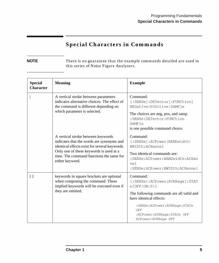
NOTE There is no guarantee that the example commands detailed are used in this series of Noise Figure Analyzers.
Special Character
Meaning Example
| A vertical stroke between parameters indicates alternative choices. The effect of the command is different depending on which parameter is selected.
Command: [:SENSe]:DETector[:FUNCtion] NEGative|POSitive|SAMPle
The choices are neg, pos, and samp. :SENSe:DETector:FUNCtion SAMPleis one possible command choice.
A vertical stroke between keywords indicates that the words are synonyms and identical effects exist for several keywords. Only one of these keywords is used at a time. The command functions the same for either keyword.
Command: [:SENSe]:ACPower:BANDwidth|BWIDth:ACHannel
Two identical commands are: :SENSe:ACPower:BANDwidth:ACHannel :SENSe:ACPower:BWIDth:ACHannel
[ ] keywords in square brackets are optional when composing the command. These implied keywords will be executed even if they are omitted.
Command: [:SENSe]:ACPower:AVERage[:STATe]OFF|ON|0|1
The following commands are all valid and have identical effects:
:SENSe:ACPower:AVERage:STATe OFF:ACPower:AVERage:STATe OFFACPower:AVERage OFF
Chapter 1 5

Programming FundamentalsSpecial Characters in Commands
< > Angle brackets around a word, or words, indicates they are not to be used literally in the command. They represent the needed item.
Command::SENSe:ACPower:CSPacing <freqency>
In this command example the word <freqency> should be replaced by an actual frequency: :SENSe:ACPower:CSPacing 9.7MHz
{ } Braces, or curly brackets, indicate an optional repeating sequence and are used to enclose one or more parameters that may be included zero or more times.
Command:[SENSe:]CORRection:CSET[1]|2|3|4:DATA:MERGe <frequency>,<rel_ampl>{,<frequency>,<rel_ampl>}
A valid form of this command is:[SENSe:]CORRection:CSET1:DATA:MERGe 740000,.94 1250000,.31 3320000,1.7
Special Character
Meaning Example
6 Chapter 1
Programming FundamentalsParameters in Commands
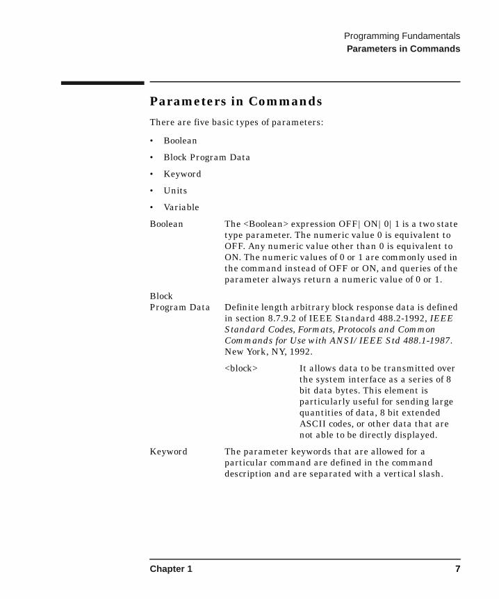
Parameters in CommandsThere are five basic types of parameters:
• Boolean
• Block Program Data
• Keyword
• Units
• Variable
Boolean The <Boolean> expression OFF|ON|0|1 is a two state type parameter. The numeric value 0 is equivalent to OFF. Any numeric value other than 0 is equivalent to ON. The numeric values of 0 or 1 are commonly used in the command instead of OFF or ON, and queries of the parameter always return a numeric value of 0 or 1.
Block Program Data Definite length arbitrary block response data is defined
in section 8.7.9.2 of IEEE Standard 488.2-1992, IEEE Standard Codes, Formats, Protocols and Common Commands for Use with ANSI/IEEE Std 488.1-1987. New York, NY, 1992.
<block> It allows data to be transmitted over the system interface as a series of 8 bit data bytes. This element is particularly useful for sending large quantities of data, 8 bit extended ASCII codes, or other data that are not able to be directly displayed.
Keyword The parameter keywords that are allowed for a particular command are defined in the command description and are separated with a vertical slash.
Chapter 1 7

Programming FundamentalsParameters in Commands
Units Numerical variables may include units. The valid units for a command depends on the variable type being used. If no units are sent, the indicated default units will be used. Units can follow the numerical value with, or without, a space.
Variable Anything that appears in angle brackets < > after a command or query header represents a User supplied parameter.
8 Chapter 1

Programming FundamentalsSCPI Termination and Separator Syntax
SCPI Termination and Separator SyntaxA terminator must be provided when an instrument is controlled using RS-232. There are several issues to be understood about choosing the proper SCPI terminator and separator when this is the case. There is no current SCPI standard for RS-232. Although one intent of SCPI is to be interface independent, <END> is only defined for IEEE 488 operation. At the time of this writing, the RS-232 terminator issue was in the process of being addressed in IEEE standard 1174.
A semicolon (;) is not a SCPI terminator, it is a separator. The purpose of the separator is to queue multiple commands or queries in order to obtain multiple actions and/or responses. Make sure that you do not attempt to use the semicolon as a terminator when using RS-232 control.
Basically all binary trace and response data is terminated with <NL><END>, as defined in Section 8.5 of IEEE Standard 488.2-1992, IEEE Standard Codes, Formats, Protocols and Common Commands for Use with ANSI/IEEE Std 488.1-1987. New York, NY, 1992.
Chapter 1 9
Programming FundamentalsImproving the NFA’s Performance
Improving the NFA’s Performance
Measurement Speed
Disabling the Noise Figure Analyzer display increases the measurement response time and as a result makes the remote command processing faster.
See “Turn Display On or Off” on page 32 for an explanation of this feature.
Copying Commands
If you want to cut and paste the command text when programming, there is a file on the CD-ROM called Commands.txt this is provided for this purpose.
10 Chapter 1
2 IEEE 488.2 Common Commands
The common commands are as specified in IEEE 488.2.
11

IEEE 488.2 Common CommandsIEEE 488.2 Common Commands
IEEE 488.2 Common Commands
Instrument Calibration Query
*CAL?
This command is included for compatibility reasons only. It has no effect. The return value is always 0.
Clear Status
*CLS
Clears the status byte. It does this by emptying the error queue and clearing all bits in all of the event registers.
See *STB?
12 Chapter 2

IEEE 488.2 Common CommandsIEEE 488.2 Common Commands
Event Status Enable Register
*ESE <integer>
Sets the bits in the standard event status enable register. This register monitors GP-IB errors and synchronization conditions such as operation complete, request control, query error, device dependent error, execution error, command error and power on. A summary bit is generated on execution of the command.
Valid input range
Integer, 0 to 255
Query command
*ESE?
Query returns the state of the standard event status enable register.
The bits defined in this register are:
Table 2-1 Standard event status enable register bits
Bit Meaning when bit asserted
0 Operation complete
2 Query error
3 Device dependent error
4 Execution error
5 Command error
6 User request
7 Power on
Chapter 2 13

IEEE 488.2 Common CommandsIEEE 488.2 Common Commands
Event Status Register Query
*ESR?
Queries and clears the standard event status register. (This is a destructive read.)
Valid input range
Integer, 0 to 255
Table 2-2 Standard event status register
Bit Meaning when bit asserted
0 Operation complete
1 Request bus control
2 Query control
3 Device dependent error
4 Execution error
5 Command error
6 User request (not used)
7 Power on
14 Chapter 2

IEEE 488.2 Common CommandsIEEE 488.2 Common Commands
Instrument Identification Query
*IDN?
Returns an instrument identification information string to GP-IB. The string will contain the model number, serial number and firmware revision. The response is organized into four fields separated by commas. The field definitions are as follows:
• Manufacturer
• Model
• Serial number
• Firmware version
For example:
Agilent Technologies, N8975A, GB40390000, A.04.06
Learn String Query
*LRN?
Returns current instrument state data. The information is in a machine readable format only. Sending the query returns the following:
SYST:SET #NMMM<state_data>
You can set the state by sending this block of data to the instrument:
SYST:SET #NMMM<state_data>
Chapter 2 15

IEEE 488.2 Common CommandsIEEE 488.2 Common Commands
Operation Complete
*OPC
Supports operations within the operation status register by setting bit 0 in the standard event status register to ‘1’ when all pending operations have finished.
Query command
*OPC?
The query stops any new commands from being processed until the current processing is complete. Then it returns a ‘1’, and the program continues. This query can be used to synchronize events of other instruments on the external bus.
State Recall
*RCL <register>
This command recalls the instrument state from the specified instrument memory register.
Valid input range
Integer, 2 to 99
Instrument Reset
*RST
This command presets the instrument to a factory pre-defined condition.
16 Chapter 2
IEEE 488.2 Common CommandsIEEE 488.2 Common Commands
State Save
*SAV <register>
This command saves the instrument state to the specified instrument memory register.
Valid input range
Integer, 2 to 99
Service Request Enable
*SRE <integer>
This command sets the value of the service request enable register. Setting a bit in this register means that the corresponding bit in the Status Byte causes a service request when set.
Valid input range
Integer, 0 to 63 and 128 to 191
Query command
*SRE?
The query returns the value of the register.
Chapter 2 17
IEEE 488.2 Common CommandsIEEE 488.2 Common Commands
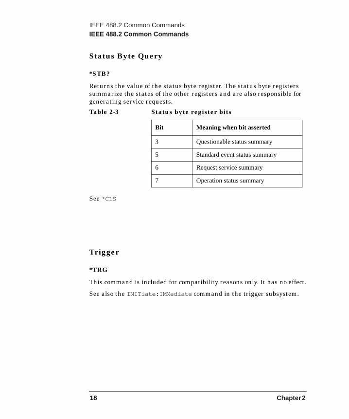
Status Byte Query
*STB?
Returns the value of the status byte register. The status byte registers summarize the states of the other registers and are also responsible for generating service requests.
See *CLS
Trigger
*TRG
This command is included for compatibility reasons only. It has no effect.
See also the INITiate:IMMediate command in the trigger subsystem.
Table 2-3 Status byte register bits
Bit Meaning when bit asserted
3 Questionable status summary
5 Standard event status summary
6 Request service summary
7 Operation status summary
18 Chapter 2

IEEE 488.2 Common CommandsIEEE 488.2 Common Commands
Self Test Query
*TST?
This query runs the instrument self-test and returns the results.
The returned value is a bitmask:
A return value of 0 means that all self tests passed.
NOTE See “Initiate a Measurement” on page 193 for an explanation on the command needed to be sent after the *TST? command has been executed in order to restart the sweep.
Wait
*WAI
This command causes the instrument to wait until all pending commands are completed before executing any additional commands.
Table 2-4 Bit Meaning when bit asserted
Bit Meaning
0 IF gain out of range.
1 IF attenuator value(s) out of range.
2 RF attenuator value(s) out of range.
3 ADC test failure.
Chapter 2 19
IEEE 488.2 Common CommandsIEEE 488.2 Common Commands
20 Chapter 2
3 CALCulate Subsystem
The CALCulate Subsystem commands are used to perform post-acquisition data processing. In effect, the collection of new data triggers the CALCulate subsystem. In the Noise Figure Analyzer, the primary functions in this subsystem are limits.
21
CALCulate SubsystemLimit Line Commands
Limit Line Commands
Number Of PointsCALCulate:LLINe[1]|2|3|4:COUNt?
Description Returns the number of points in the selected limit line.
Valid return range 0 to 201 points
Query command CALCulate:LLINe2:COUNt?
22 Chapter 3

CALCulate SubsystemLimit Line Commands
Limit Line DataCALCulate:LLINe[1]|2|3|4:DATA<frequency>,<ampl>,<connected>,<frequency>,<ampl>,<connected>{,<frequency>,<ampl>,<connected>}
Description Defines limit line values.
The amplitude values of the limit lines have no units of their own. Instead they take on the units of the graph to which the limit line is applied. If the units of the graph are changed then the limit line values take on the new units without rescaling.
• <frequency> - is a frequency in Hz. Frequency values do not allow units (e.g. MHz) to be specified, they are always in Hz.
• <ampl> - amplitude values are unitless.• <connected> - connected values are either 0 or 1. A 1 means this
point is connected to the previously defined point to define the limit line. A 0 means this is a point of discontinuity and is not connected to the preceding point.
Limit lines 1 and 2 apply to the trace that is displayed in the upper graph. Limit lines 3 and 4 apply to the trace that is displayed in the lower graph.
Valid input range 1 to 201 points
Default Limit lines are empty.
Query command CALCulate:LLINe[1]|2|3|4:DATA?
Chapter 3 23
CALCulate SubsystemLimit Line Commands
Display ControlCALCulate:LLINe[1]|2|3|4:DISPlay[:STATe]OFF|ON|0|1
NOTE Limit lines are only valid for graphical displays.
Description Controls whether or not the given limit line is displayed.
Default Off
Query command CALCulate:LLINe[1]|2|3|4:DISPlay[STATe]?
Limit Test ControlCALCulate:LLINe[1]|2|3|4[:STATe]OFF|ON|0|1
Description This command turns the limit testing on or off for the given limit line. The results of the limit testing can be obtained from the Questionable Integrity Status Register.
Default Off
Query command CALCulate:LLINe[1]|2|3|4[:STATe]?
24 Chapter 3

CALCulate SubsystemLimit Line Commands
Limit TypeCALCulate:LLINe[1]|2|3|4:TYPE UPPer|LOWer
Description Sets the limit line type. An upper line will be used as the maximum allowable value when comparing with the data. A lower limit line defines the minimum allowable value.
Default UPPer
Query command CALCulate:LLINe1:TYPE?
Chapter 3 25

CALCulate SubsystemLimit Line Commands
26 Chapter 3
4 CALibration Subsystem
The CALibration Subsystem commands control the self-alignment and self-diagnostic processes.
27

CALibration SubsystemCalibration Commands
Calibration Commands
Auto Alignment ControlCALibration:AUTO[:STATe] OFF|ON|0|1
Description Turns the automatic alignment routines on and off. These are run in the background. See also “Auto Alignment Mode”.
Default On
Query command CALibration:AUTO[:STATe]?
Auto Alignment ModeCALibration:AUTO:MODE POINt|SWEep
Description The automatic alignment routines run in the background. This allows you to choose when an alignment occurs.
• POINt - after each point in a sweep or between successive measurements when making fixed frequency measurements.
• SWEep - at start of each sweep. This is equivalent to POINt when making fixed frequency measurements.
Default SWEep
Query command CALibration:AUTO:MODE?
28 Chapter 4

CALibration SubsystemCalibration Commands
Frequency Calibration Source QueryCALibration:FREQuency:REFerence?
Description Returns the source of the active calibration frequency reference.
The following can be returned:
• INT — the source is internal
• EXT — the source is external
Frequency Calibration Coarse AdjustmentCALibration:FREQuency:REFerence:COARse <integer>
Description Performs the frequency calibration DAC coarse adjustment.
Valid input range 0 to 255
Default value Factory set
Query command CALibration:FREQuency:REFerence:COARse?
Frequency Calibration Fine AdjustmentCALibration:FREQuency:REFerence:FINE <integer>
Description Performs the frequency calibration DAC fine adjustment.
Valid input range 0 to 255
Default value Factory set
Query command CALibration:FREQuency:REFerence:FINE?
Chapter 4 29
CALibration SubsystemCalibration Commands
NOTE YTF settings are only applicable to models N8974A and N8975A.
Calibrate YIG Tuned FilterCALibration:YTF
Description Performs an alignment of the YIG tuned filter. The results are not permanently stored by this command and will not survive a power cycle.
NOTE To save the results run the command CALibration:YTF:STORe
.
Store YIG Tuned Filter Calibration ResultsCALibration:YTF:STORe
Description Permanently stores the current set of YIG tuned filter results so that they will survive a power cycle.
30 Chapter 4
5 DISPlay Subsystem
The DISPlay Subsystem controls the selection and presentation of the measurement results.
31
DISPlay SubsystemDisplay Commands
Display Commands
Adjust Viewing AngleDISPlay:ANGLe <integer>
Description Changes the viewing angle for better viewing in different environments.
Valid input range 1 to 7
Default 4
Query command DISPlay:ANGLe?
Turn Display On or OffDISPlay:ENABle[:STATe] OFF|ON|0|1
Description Turns the display on or off. Turning off the display prolongs its life.
Default On
Query command DISPlay:ENABle[:STATe]?
32 Chapter 5
DISPlay SubsystemDisplay Commands
Turn Full Screen On or OffDISPlay:FULLscreen[:STATe] OFF|ON|0|1
Description Turns the full screen display on and off.
Default Off
Query command DISPlay:FULLscreen[:STATe]?
Display FormatDISPlay:FORMat GRAPh|TABLe|METer
Description Sets the format of the display to either graph, table or meter.
Default GRAPh
Query command DISPlay:FORMat?
Chapter 5 33

DISPlay SubsystemDisplay Commands
Date Display Format
DISPlay:ANNotation:CLOCk:DATE:FORMat MDY|DMY
Description Allows you to set the format in which the date is displayed. To set the date refer to “System Date” on page 176.
Default MDY
Query command DISPlay:ANNotation:CLOCk:DATE:FORMat?
Clock Display Control
DISPlay:ANNotation:CLOCk[:STATe] OFF|ON|0|1
Description Used to turn the date and time display on and off.
Default On
Query command DISPlay:ANNotation:CLOCk[:STATe]?
34 Chapter 5

DISPlay SubsystemDisplay Commands
Result Display Units
DISPlay:DATA:UNITs <result>,<units>
Description Set the units with which the given measurement is reported. The set of applicable units depends on the measurement, they are:
Query command DISPlay:DATA:UNITs?<result>
Table 5-1 Set of applicable measurement units
DATA <result> <units> Default
Noise Figure NFIGure DB|LINeara DB
Gain GAIN DB|LINear DB
Y Factor YFACtor DB|LINear DB
Effective Temp.b TEFFective K|CEL|FAR K
Hot Power Densityc PHOT DB|LINear DB
Cold Power Densityc PCOLd DB|LINear DB
a. Linear noise measurements are also known as noise factor.b. CEL and FAR represent °C and °F respectively.c. Hot and cold power values represent a value proportional to input
power.
Chapter 5 35
DISPlay SubsystemDisplay Commands
Corrected Result Display ControlDISPlay:DATA:CORRections[:STATe] OFF|ON|0|1
Description Enables or disables the display of corrected data.
Until a user calibration has been performed then attempting to turn corrections on results in the SCPI error -221, Settings conflict.
Default Off
Query command DISPlay:DATA:CORRections[:STATe]?
36 Chapter 5

DISPlay SubsystemDisplay Commands
Select Result For Display
DISPlay:DATA:TRACe[[1]|2] <result>
NOTE Trace 1 and trace 2 must not be set to show the same result.
Description Sets the selected result to be displayed in the selected trace. Trace 1 is the upper trace in graph mode, the center column in table mode and the center value in meter mode. Trace 2 is the lower trace in graph mode, the right-hand column in table mode and the right-hand value in meter mode.
Result The result can be one off:
• NFIGure — Noise Figure
• GAIN — Gain
• YFACtor — Y Factor
• TEFFective — Effective temperature
• PHOT — Hot power density
• PCOLd — Cold power density
Default TRACe1 is NFIGure
TRACe2 is GAIN
Query command DISPlay:DATA:TRACe[[1]|2]?
Chapter 5 37
DISPlay SubsystemGraphical Display Format Commands
Graphical Display Format CommandsThe commands in this section are specific to the graphical display format.
The graph limits and levels affect the data display only and do not affect the measurement process or results. The applicable range depends on the selected measurement.
Graph Annotation ControlDISPlay:ANNotation[:STATe] OFF|ON|0|1
Description Turns the screen annotation on or off.
Default On
Query command DISPlay:ANNotation[:STATe]?
Graph Graticule ControlDISPlay:GRATicule[:STATe] OFF|ON|0|1
Description Turns the graticule on or off.
Default On
Query command DISPlay:GRATicule[:STATe]?
38 Chapter 5

DISPlay SubsystemGraphical Display Format Commands
Graph Window Zoom
DISPlay:ZOOM:WINDow OFF|UPPer|LOWer
Description Expands the selected window to fill the whole display. The windows correspond to the upper and lower graphs in the dual graph display.
Options • OFF — Returns the display to dual graph.
• UPPer — Zoom the upper window.
• LOWer — Zoom the lower window.
Default Off
Query command DISPlay:ZOOM:WINDow?
The query returns one of the three options detailed above.
Combined Graph DisplayDISPlay:TRACe:COMBined[:STATe] OFF|ON|0|1
Description Enables or disables combined graph display when in graph display mode. When enabled (On), the combined graph display combines the two displayed traces into the same graph. When disabled (Off) returns any zoomed display back to dual graph format.
Default Off
Query command DISPlay:TRACe:COMBined[:STATe]?
Chapter 5 39
DISPlay SubsystemGraphical Display Format Commands
Reference Level ValueDISPlay:TRACe:Y[:SCALe]:RLEVel:VALue <result>,<value>
Description Sets the value of the display reference level. The result value can be one of the following:
NOTE The reference level is limited to the current scale upper and lower limit values.
• NFIGure — Noise Figure
• GAIN — Gain
• YFACtor — Y-Factor
• TEFFective — Effective Temp
• PHOT — Hot Power Density
• PCOLd — Cold Power Density
Valid input range The valid input range for each result is as follows:
• Noise Figure — -100.0 to 100.0dB
• Gain — -100.0 to 100.0dB
• Y Factor — -100.0 to 100.0dB
• Effective Temp — -100000000 to 100000000K
• Hot Power Density — -100.0 to 100.0dB
• Cold Power Density — -100.0 to 100.0dB
Default • Noise Figure — 4.0dB
• Gain — 15.000dB
• Y Factor — 5.000dB
• Effective Temp — 1000.0 K
• Hot Power Density — 5.000dB
• Cold Power Density — 5.000dB
Query command DISPlay:TRACe:Y[:SCALe]:RLEVel:VALue? <result>
40 Chapter 5

DISPlay SubsystemGraphical Display Format Commands
Reference Level ControlDISPlay:TRACe:Y[:SCALe]:RLEVel[:STATe]<result>,OFF|ON|0|1
Description Determines whether or not the specified result’s reference level line will be shown when the result is displayed graphically.
Default OFF
Query command DISPlay:TRACe:Y[:SCALe]:RLEVel[:STATe]? <result>
Chapter 5 41
DISPlay SubsystemGraphical Display Format Commands
Graph Scale Per DivisionDISPlay:TRACe:Y[:SCALe]:PDIVision <result>,<value>
Description Sets the per-division display scaling for the selected result. The options available are as follows:
• NFIGure — Noise Figure
• GAIN — Gain
• YFACtor — Y-Factor
• TEFFective — Effective Temp
• PHOT — Hot Power Density
• PCOLd — Cold Power Density
Valid input range • Noise Figure — 0.001 to 20.0dB
• Gain — 0.001 to 20.0dB
• Y Factor — 0.001 to 20.0dB
• Effective Temp — 0.1 to 20000000K
• Hot Power Density — 0.001 to 20.0dB
• Cold Power Density — 0.001 to 20.0dB
Default • Noise Figure — 1.0dB
• Gain — 5.0dB
• Y Factor — 1.0dB
• Effective Temp — 200K
• Hot Power Density — 1.0dB
• Cold Power Density — 1.0dB
Query command DISPlay:TRACe:Y[:SCALe]:PDIVision? <result>
42 Chapter 5
DISPlay SubsystemGraphical Display Format Commands
Graph Lower LimitDISPlay:TRACe:Y[:SCALe]:LOWer <trace>,<value>
Description Sets the lower limit for the selected trace. The options available are as follows:
• NFIGure — Noise Figure
• GAIN — Gain
• YFACtor — Y-Factor
• TEFFective — Effective Temp
• PHOT — Hot Power Density
• PCOLd — Cold Power Density
Valid input range • Noise Figure — -100 to 99.99dB
• Gain — -100 to 99.99dB
• Y Factor — -100 to 99.99dB
• Effective Temp — -100000000 to 99990000K
• Hot Power Density — -100 to 99.99dB
• Cold Power Density — -100 to 99.99dB
Default • Noise Figure — -1.0dB
• Gain — -10.0dB
• Y Factor — 0.0dB
• Effective Temp — 0.0K
• Hot Power Density — 0.0dB
• Cold Power Density — 0.0dB
Query command DISPlay:TRACe:Y[:SCALe]:LOWer? <trace>
Chapter 5 43
DISPlay SubsystemGraphical Display Format Commands
Graph Upper LimitDISPlay:TRACe:Y[:SCALe]:UPPer <trace>,<value>
Description Sets the upper limit for the selected trace. The options available are as follows:
• NFIGure — Noise Figure
• GAIN — Gain
• YFACtor — Y-Factor
• TEFFective — Effective Temp
• PHOT — Hot Power Density
• PCOLd — Cold Power Density
Valid input range • Noise Figure — -99.99 to 100.0dB
• Gain — -99.99 to 100.0dB
• Y Factor — -99.99 to 100.0dB
• Effective Temp — -99990000 to 100000000K
• Hot Power Density — -99.99 to 100.0dB
• Cold Power Density — -99.99 to 100.0dB
Default • Noise Figure — 9.0dB
• Gain — 40.0dB
• Y Factor — 10.0dB
• Effective Temp — 2000.0K
• Hot Power Density — 10.0dB
• Cold Power Density — 10.0dB
Query command DISPlay:TRACe:Y[:SCALe]:UPPer? <trace>
44 Chapter 5
6 HCOPy Subsystem
The HCOPy subsystem controls the setup of printing to an external device.
45
HCOPy SubsystemHardcopy Commands
Hardcopy Commands
Abort PrintoutHCOPy:ABORt
Description The HCOPy:ABORt command aborts hard copy printout of results. This is equivalent to pressing the ESC hardkey when a print is in progress.
Printer TypeHCOPy:DEVice:TYPE AUTO|CUSTom|NONE
Description The HCOPy:DEVice:TYPE command sets up the printer by selecting the printer type. The following options are available:
• AUTO - the instrument queries the printer to determine it’s type and automatically sets itself for that printer
• CUSTom - allows you to select a printer type if your printer is not auto-configurable.
• NONE - tells the instrument that the hardcopy output device is not a printer
Query command HCOPy:DEVice:TYPE?
Default AUTO
46 Chapter 6
HCOPy SubsystemHardcopy Commands
Print CommandHCOPy[:IMMediate]
Description The HCOPy[:IMMediate] command initiates printing of the current display data.
Printer Color ControlHCOPy:IMAGe:COLor[:STATe] OFF|ON|0|1
Description HCOPy:IMAGe:COLor[:STATe] selects between color and monochrome mode for hardcopy output.
Default ON
Query command HCOPy:IMAGe:COLor[:STATe]?
Form FeedHCOPy:ITEM:FFEed[:IMMediate]
Description Sends the printer a form feed command.
Chapter 6 47
HCOPy SubsystemHardcopy Commands
Page OrientationHCOPy:PAGE:ORIentation LANDscape|PORTrait
Description Specifies the orientation of the print.
Default LANDscape
Query command HCOPy:PAGE:ORIentation?
Prints Per PageHCOPy:PAGE:PRINts <integer>
Description HCOPy:PAGE:PRINts sets the number of display print outputs sent to print on one piece of paper, before a form feed is sent.
Valid input range Integer, 1 or 2
Default 1
Query command HCOPy:PAGE:PRINts?
48 Chapter 6
7 INPut Subsystem
The INPut subsystem allows you to set maximum and minimum values of selected attenuators used when calibrating the NFA.
49
INPut SubsystemInput Commands
Input Commands
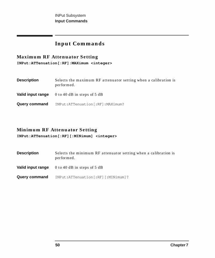
Maximum RF Attenuator SettingINPut:ATTenuation[:RF]:MAXimum <integer>
Description Selects the maximum RF attenuator setting when a calibration is performed.
Valid input range 0 to 40 dB in steps of 5 dB
Query command INPut:ATTenuation[:RF]:MAXimum?
Minimum RF Attenuator SettingINPut:ATTenuation[:RF][:MINimum] <integer>
Description Selects the minimum RF attenuator setting when a calibration is performed.
Valid input range 0 to 40 dB in steps of 5 dB
Query command INPut:ATTenuation[:RF][:MINimum]?
50 Chapter 7

INPut SubsystemInput Commands
NOTE Microwave (MWAVe) attenuation settings are only applicable to models N8974A and N8975A.
Maximum Microwave Attenuator SettingINPut:ATTenuation:MWAVe:MAXimum <integer>
Description Selects the maximum microwave attenuator setting when a calibration is performed.
Valid input range 0 to 30 dB in 15 dB steps
Default 0 dB
Query command INPut:ATTenuation:MWAVe:MAXimum?
Minimum Microwave Attenuator SettingINPut:ATTenuation:MWAVe[:MINimum] <integer>
Description Selects the minimum microwave attenuator setting when a calibration is performed.
Valid input range 0 to 30 dB in 15 dB steps
Default 0 dB
Query command INPut:ATTenuation:MWAVe[:MINimum]?
Chapter 7 51

INPut SubsystemInput Commands
52 Chapter 7
8 MEASure Subsystem
The MEASure Subsystem allows you to retrieve measurement data from the NFA.
53

MEASure Subsystem
NOTE Commands in this subsystem use the SCPI NAN value (9.91E+37) to indicate that there has been a problem in performing the calculation of the requested result. This typically happens when an attempt is made to retrieve corrected data without first performing a user calibration.
54 Chapter 8
MEASure SubsystemFETCh Commands
FETCh CommandsFETCh commands retrieve results for the most recently completed fixed frequency or swept measurement. When no result is available, but a measurement is in progress, the command will not return until the measurement completes.
When no result is available and there is no measurement in progress, no data is returned and error -230,”Data corrupt or stale” is placed in the error queue.
Sweep results are returned as a list of comma separated values, one value for each measurement frequency.
FETCh output is terminated with the ASCII NL character.
Chapter 8 55
MEASure SubsystemFetch Swept Frequency Results
Fetch Swept Frequency Results
Gain Measurement
FETCh[:ARRay][:DATA]:CORRected:GAIN? [DB|LINear]
Description Return the gain values from the most recently completed swept frequency measurement. The returned values are in the specified units. If no units are specified then the default units are used.
Default dB
Example FETC:CORR:GAIN? LIN
Corrected Noise Figure Measurement
FETCh[:ARRay][:DATA]:CORRected:NFIGure? [DB|LINear]
Description Return the corrected noise figure values from the most recently completed swept frequency measurement. The returned values are in the specified units. If no units are specified then the default units are used.
Default dB
Example FETC:CORR:NFIG?
56 Chapter 8
MEASure SubsystemFetch Swept Frequency Results
Corrected Cold Power Measurement
FETCh[:ARRay][:DATA]:CORRected:PCOLd? [DB|LINear]
Description Return the corrected cold power values from the most recently completed swept frequency measurement. The returned values are in the specified units. If no units are specified then the default units are used.
The instrument makes cold power measurements with the noise source switched off. The reported value is a power level which is relative to the power at the input.
Default dB
Example FETC:CORR:PCOL?
Corrected Hot Power Measurement
FETCh[:ARRay][:DATA]:CORRected:PHOT [DB|LINear]
Description Return the corrected hot power values from the most recently completed swept frequency measurement. The returned values are in the specified units. If no units are specified then the default units are used.
The instrument makes hot power measurements with the noise source switched on. The reported value is a power level which is relative to the power at the input.
Default dB
Example FETC:CORR:PHOT? DB
Chapter 8 57

MEASure SubsystemFetch Swept Frequency Results
Corrected Effective Temperature Measurement
FETCh[:ARRay][:DATA]:CORRected:TEFFecive [K|CEL|FAR]
Description Return the corrected effective temperature values from the most recently completed swept frequency measurement. The returned values are in the specified units. If no units are specified then the default units are used.
Default K
Example FETC:CORR:TEFF? CEL
Tcold Values
FETCh[:ARRay][:DATA]:TCOLD? [K|CEL|FAR]
Description Return the Tcold values used in calculating swept measurement results. The returned values are in the specified units. If no units are specified then the default units are used.
Default K
Example FETC:TCOLD?
58 Chapter 8
MEASure SubsystemFetch Swept Frequency Results
Uncorrected Noise Figure Measurement
FETCh[:ARRay][:DATA]:UNCorrected:NFIGure? [DB|LINear]
Description Return the uncorrected noise figure values from the most recently completed swept frequency measurement. The returned values are in the specified units. If no units are specified then the default units are used.
Default dB
Example FETC:UNC:NFIG?
Uncorrected Cold Power Measurement
FETCh[:ARRay][:DATA]:UNCorrected:PCOLd? [DB|LINear]
Description Return the uncorrected cold power values from the most recently completed swept frequency measurement. The returned values are in the specified units. If no units are specified then the default units are used.
The instrument makes cold power measurements with the noise source switched off. The reported value is a power level which is relative to the power at the input.
Default dB
Example FETC:UNC:PCOL?
Chapter 8 59

MEASure SubsystemFetch Swept Frequency Results
Uncorrected Hot Power Measurement
FETCh[:ARRay][:DATA]:UNCorrected:PHOT [DB|LINear]
Description Return the uncorrected hot power values from the most recently completed swept frequency measurement. The returned values are in the specified units. If no units are specified then the default units are used.
The instrument makes hot power measurements with the noise source switched on. The reported value is a power level which is relative to the power at the input.
Default dB
Example FETC:UNC:PHOT? DB
Uncorrected Effective Temperature Measurement
FETCh[:ARRay][:DATA]:UNCorrected:TEFFecive [K|CEL|FAR]
Description Return the uncorrected effective temperature values from the most recently completed swept frequency measurement. The returned values are in the specified units. If no units are specified then the default units are used.
Default K
Example FETC:UNC:TEFF? CEL
60 Chapter 8
MEASure SubsystemFetch Swept Frequency Results
Y-Factor Measurement
FETCh[:ARRay][:DATA]:UNCorrected:YFACtor? [DB|LINear]
Description Return the Y-factor values from the most recently completed swept frequency measurement. The returned values are in the specified units. If no units are specified then the default units are used.
Default dB
Example FETC:CORR:YFAC? LIN
Chapter 8 61

MEASure SubsystemFetch Fixed Frequency Results
Fetch Fixed Frequency Results
Gain Measurement
FETCh:SCALar[:DATA]:CORRected:GAIN? [DB|LINear]
Description Return the gain value from the most recently completed fixed frequency measurement. The returned value is in the specified units. If no units are specified then the default units are used.
Default dB
Example FETC:SCAL:CORR:GAIN? LIN
Corrected Noise Figure Measurement
FETCh:SCALar[:DATA]:CORRected:NFIGure? [DB|LINear]
Description Return the corrected noise figure value from the most recently completed fixed frequency measurement. The returned value is in the specified units. If no units are specified then the default units are used.
Default dB
Example FETC:SCAL:CORR:NFIG?
62 Chapter 8

MEASure SubsystemFetch Fixed Frequency Results
Corrected Cold Power Measurement
FETCh:SCALar[:DATA]:CORRected:PCOLd? [DB|LINear]
Description Return the corrected cold power value from the most recently completed fixed frequency measurement. The returned value is in the specified units. If no units are specified then the default units are used.
The instrument makes cold power measurements with the noise source switched off. The reported value is a power level which is relative to the power at the input.
Default dB
Example FETC:SCAL:CORR:PCOL?
Corrected Hot Power Measurement
FETCh:SCALar[:DATA]:CORRected:PHOT [DB|LINear]
Description Return the corrected hot power value from the most recently completed fixed frequency measurement. The returned value is in the specified units. If no units are specified then the default units are used.
The instrument makes hot power measurements with the noise source switched on. The reported value is a power level which is relative to the power at the input.
Default dB
Example FETC:SCAL:CORR:PHOT? DB
Chapter 8 63
MEASure SubsystemFetch Fixed Frequency Results
Corrected Effective Temperature Measurement
FETCh:SCALar[:DATA]:CORRected:TEFFecive [K|CEL|FAR]
Description Return the corrected effective temperature value from the most recently completed fixed frequency measurement. The returned value is in the specified units. If no units are specified then the default units are used.
Default K
Example FETC:SCAL:CORR:TEFF? CEL
Tcold Value
FETCh:SCALar[:DATA]:TCOLD? [K|CEL|FAR]
Description Return the Tcold value used in calculating fixed frequency measurement results. The returned value is in the specified units. If no units are specified then the default units are used.
Default K
Example FETC:SCAL:TCOLD?
64 Chapter 8

MEASure SubsystemFetch Fixed Frequency Results
Uncorrected Noise Figure Measurement
FETCh:SCALar[:DATA]:UNCorrected:NFIGure? [DB|LINear]
Description Return the uncorrected noise figure value from the most recently completed fixed frequency measurement. The returned value is in the specified units. If no units are specified then the default units are used.
Default dB
Example FETC:SCAL:UNC:NFIG?
Uncorrected Cold Power Measurement
FETCh:SCALar[:DATA]:UNCorrected:PCOLd? [DB|LINear]
Description Return the uncorrected cold power value from the most recently completed fixed frequency measurement. The returned value is in the specified units. If no units are specified then the default units are used.
The instrument makes cold power measurements with the noise source switched off. The reported value is a power level which is relative to the power at the input.
Default dB
Example FETC:SCAL:UNC:PCOL?
Chapter 8 65

MEASure SubsystemFetch Fixed Frequency Results
Uncorrected Hot Power Measurement
FETCh:SCALar[:DATA]:UNCorrected:PHOT [DB|LINear]
Description Return the uncorrected hot power value from the most recently completed fixed frequency measurement. The returned value is in the specified units. If no units are specified then the default units are used.
The instrument makes hot power measurements with the noise source switched on. The reported value is a power level which is relative to the power at the input.
Default dB
Example FETC:SCAL:UNC:PHOT? DB
Uncorrected Effective Temperature Measurement
FETCh:SCALar[:DATA]:UNCorrected:TEFFecive [K|CEL|FAR]
Description Return the uncorrected effective temperature value from the most recently completed fixed frequency measurement. The returned value is in the specified units. If no units are specified then the default units are used.
Default K
Example FETC:SCAL:UNC:TEFF? CEL
66 Chapter 8

MEASure SubsystemFetch Fixed Frequency Results
Y-Factor Measurement
FETCh:SCALar[:DATA]:UNCorrected:YFACtor? [DB|LINear]
Description Return the Y-factor value from the most recently completed fixed frequency measurement. The returned value is in the specified units. If no units are specified then the default units are used.
Default dB
Example FETC:SCAL:UNC:YFAC? LIN
Chapter 8 67
MEASure SubsystemREAD Commands
READ CommandsThe READ commands initiate a measurement and retrieve the results.
Sweep results are returned as a list of comma separated values, one value for each measurement frequency.
READ output is terminated with the ASCII NL character.
68 Chapter 8

MEASure SubsystemRead Swept Frequency Results
Read Swept Frequency Results
Gain Measurement
READ[:ARRay][:DATA]:CORRected:GAIN? [DB|LINear]
Description Initiate a swept frequency measurement and return the gain results. The returned values are in the specified units. If no units are specified then the default units are used.
Default dB
Example READ:CORR:GAIN? LIN
Corrected Noise Figure Measurement
READ[:ARRay][:DATA]:CORRected:NFIGure? [DB|LINear]
Description Initiate a swept frequency measurement and return the corrected noise figure results. The returned values are in the specified units. If no units are specified then the default units are used.
Default dB
Example READ:CORR:NFIG?
Chapter 8 69
MEASure SubsystemRead Swept Frequency Results
Corrected Cold Power Measurement
READ[:ARRay][:DATA]:CORRected:PCOLd? [DB|LINear]
Description Initiate a swept frequency measurement and return the corrected cold power results. The returned values are in the specified units. If no units are specified then the default units are used.
The instrument makes cold power measurements with the noise source switched off. The reported value is a power level which is relative to the power at the input.
Default dB
Example READ:CORR:PCOL?
Corrected Hot Power Measurement
READ[:ARRay][:DATA]:CORRected:PHOT [DB|LINear]
Description Initiate a swept frequency measurement and return the corrected hot power results. The returned values are in the specified units. If no units are specified then the default units are used.
The instrument makes hot power measurements with the noise source switched on. The reported value is a power level which is relative to the power at the input.
Default dB
Example READ:CORR:PHOT? DB
70 Chapter 8
MEASure SubsystemRead Swept Frequency Results
Corrected Effective Temperature Measurement
READ[:ARRay][:DATA]:CORRected:TEFFecive [K|CEL|FAR]
Description Initiate a swept frequency measurement and return the corrected effective temperature results. The returned values are in the specified units. If no units are specified then the default units are used.
Default K
Example READ:CORR:TEFF? CEL
Tcold Values
READ[:ARRay][:DATA]:TCOLD? [K|CEL|FAR]
Description Initiate a swept frequency measurement and return the Tcold values used in calculating measurement results. The returned values are in the specified units. If no units are specified then the default units are used.
Default K
Example READ:TCOLD? CEL
Chapter 8 71

MEASure SubsystemRead Swept Frequency Results
Uncorrected Noise Figure Measurement
READ[:ARRay][:DATA]:UNCorrected:NFIGure? [DB|LINear]
Description Initiate a swept frequency measurement and return the uncorrected noise figure results. The returned values are in the specified units. If no units are specified then the default units are used.
Default dB
Example READ:UNC:NFIG?
Uncorrected Cold Power Measurement
READ[:ARRay][:DATA]:UNCorrected:PCOLd? [DB|LINear]
Description Initiate a swept frequency measurement and return the uncorrected cold power results. The returned values are in the specified units. If no units are specified then the default units are used.
The instrument makes cold power measurements with the noise source switched off. The reported value is a power level which is relative to the power at the input.
Default dB
Example READ:UNC:PCOL?
72 Chapter 8
MEASure SubsystemRead Swept Frequency Results
Uncorrected Hot Power Measurement
READ[:ARRay][:DATA]:UNCorrected:PHOT [DB|LINear]
Description Initiate a swept frequency measurement and return the uncorrected hot power results. The returned values are in the specified units. If no units are specified then the default units are used.
The instrument makes hot power measurements with the noise source switched on. The reported value is a power level which is relative to the power at the input.
Default dB
Example READ:UNC:PHOT? DB
Uncorrected Effective Temperature Measurement
READ[:ARRay][:DATA]:UNCorrected:TEFFecive [K|CEL|FAR]
Description Initiate a swept frequency measurement and return the uncorrected effective temperature results. The returned values are in the specified units. If no units are specified then the default units are used.
Default K
Example READ:UNC:TEFF? CEL
Chapter 8 73

MEASure SubsystemRead Swept Frequency Results
Y-Factor Measurement
READ[:ARRay][:DATA]:UNCorrected:YFACtor? [DB|LINear]
Description Initiate a swept frequency measurement and return the Y-factor results. The returned values are in the specified units. If no units are specified then the default units are used.
Default dB
Example READ:CORR:YFAC? LIN
74 Chapter 8

MEASure SubsystemRead Fixed Frequency Results
Read Fixed Frequency Results
Gain Measurement
READ:SCALar[:DATA]:CORRected:GAIN? [DB|LINear]
Description Initiate a fixed frequency measurement and return the gain results. Return the gain values from the most recently completed fixed frequency measurement. The returned value is in the specified units. If no units are specified then the default units are used.
Default dB
Example READ:SCAL:CORR:GAIN? LIN
Corrected Noise Figure Measurement
READ:SCALar[:DATA]:CORRected:NFIGure? [DB|LINear]
Description Initiate a fixed frequency measurement and return the corrected noise figure result. The returned value is in the specified units. If no units are specified then the default units are used.
Default dB
Example READ:SCAL:CORR:NFIG?
Chapter 8 75

MEASure SubsystemRead Fixed Frequency Results
Corrected Cold Power Measurement
READ:SCALar[:DATA]:CORRected:PCOLd? [DB|LINear]
Description Initiate a fixed frequency measurement and return the corrected cold power result. The returned value is in the specified units. If no units are specified then the default units are used.
The instrument makes cold power measurements with the noise source switched off. The reported value is a power level which is relative to the power at the input.
Default dB
Example READ:SCAL:CORR:PCOL?
Corrected Hot Power Measurement
READ:SCALar[:DATA]:CORRected:PHOT [DB|LINear]
Description Initiate a fixed frequency measurement and return the corrected hot power result. The returned value is in the specified units. If no units are specified then the default units are used.
The instrument makes hot power measurements with the noise source switched on. The reported value is a power level which is relative to the power at the input.
Default dB
Example READ:SCAL:CORR:PHOT? DB
76 Chapter 8

MEASure SubsystemRead Fixed Frequency Results
Corrected Effective Temperature Measurement
READ:SCALar[:DATA]:CORRected:TEFFecive [K|CEL|FAR]
Description Initiate a fixed frequency measurement and return the corrected effective temperature result. The returned value is in the specified units. If no units are specified then the default units are used.
Default K
Example READ:SCAL:CORR:TEFF? CEL
Tcold Values
READ:SCALar[:DATA]:TCOLD? [K|CEL|FAR]
Description Initiate a fixed frequency measurement and return the Tcold value used in calculating measurement results. The returned value is in the specified units. If no units are specified then the default units are used.
Default K
Example READ:SCAL:TCOLD?
Chapter 8 77
MEASure SubsystemRead Fixed Frequency Results
Uncorrected Noise Figure Measurement
READ:SCALar[:DATA]:UNCorrected:NFIGure? [DB|LINear]
Description Initiate a fixed frequency measurement and return the uncorrected noise figure result. The returned value is in the specified units. If no units are specified then the default units are used.
Default dB
Example READ:SCAL:UNC:NFIG?
Uncorrected Cold Power Measurement
READ:SCALar[:DATA]:UNCorrected:PCOLd? [DB|LINear]
Description Initiate a fixed frequency measurement and return the uncorrected cold power result. The returned value is in the specified units. If no units are specified then the default units are used.
The instrument makes cold power measurements with the noise source switched off. The reported value is a power level which is relative to the power at the input.
Default dB
Example READ:SCAL:UNC:PCOL?
78 Chapter 8
MEASure SubsystemRead Fixed Frequency Results
Uncorrected Hot Power Measurement
READ:SCALar[:DATA]:UNCorrected:PHOT [DB|LINear]
Description Initiate a fixed frequency measurement and return the uncorrected hot power result. The returned value is in the specified units. If no units are specified then the default units are used.
The instrument makes hot power measurements with the noise source switched on. The reported value is a power level which is relative to the power at the input.
Default dB
Example READ:SCAL:UNC:PHOT? DB
Uncorrected Effective Temperature Measurement
READ:SCALar[:DATA]:UNCorrected:TEFFecive [K|CEL|FAR]
Description Initiate a fixed frequency measurement and return the uncorrected effective temperature result. The returned value is in the specified units. If no units are specified then the default units are used.
Default K
Example READ:SCAL:UNC:TEFF? CEL
Chapter 8 79
MEASure SubsystemRead Fixed Frequency Results
Y-Factor Measurement
READ:SCALar[:DATA]:UNCorrected:YFACtor? [DB|LINear]
Description Initiate a fixed frequency measurement and return the Y-factor result. The returned value is in the specified units. If no units are specified then the default units are used.
Default dB
Example READ:SCAL:UNC:YFAC? LIN
80 Chapter 8
9 MMEMory Subsystem
The MMEMory subsystem provides access to mass storage devices.
81
MMEMory SubsystemMass Memory Subsystem
Mass Memory SubsystemThere are two types of mass storage device:
• the 3.5 inch disk drive (high-density, 2.0 MBytes) specified by A:
• an area of flash memory, specified by C:
The mass storage device is included at the beginning of the filename, for example, ’C:STATE1.STA’ . Mass storage device and file names are represented by strings and therefor must be enclosed in quotation marks.
82 Chapter 9

MMEMory SubsystemLoad Commands
Load Commands
Load Limit LineMMEMory:LOAD:LIMit LLINe1|LLINe2|LLINe3|LLINe4,<file_name>
Description Load a limit line from the specified file.
The filename extension is .LIM. Specifying a different filename extension results in SCPI error +776,"Incorrect filename, allowable extension LIM".
Example MMEM:LOAD:LIM LLINe2,’c:mylimit.lim’
Load Instrument StateMMEMory:LOAD:STATe 1,<file_name>
Description The contents of the file are loaded into the current instrument state. As well as instrument parameter values, the state information includes user calibration data and, if present, the reference (memory) trace.
The filename extension is .STA . Specifying a different filename extension results in SCPI error +777,"Incorrect filename, allowable extension STA ".
NOTE Register 1 represents the active instrument settings.
Valid input range The only permissible register number is 1.
Example MMEM:LOAD:STATE 1,’c:mystate.sta’
Chapter 9 83
MMEMory SubsystemLoad Commands
Load ENR TableMMEMory:LOAD:ENR CALibration|MEASurement,<file_name>
Description Load an ENR table, from the specified file to either the calibration or measurement ENR tables. The filename extension is.ENR. Specifying a different filename extension results in SCPI error +770,"Incorrect filename, allowable extension ENR".
Example MMEM:LOAD:ENR MEAS,’c:myenr.enr’
Load Frequency ListMMEMory:LOAD:FREQuency <file_name>
Description Load the frequency table from the specified file.
The filename extension is.LST . Specifying a different filename extension results in SCPI error +773,"Incorrect filename, allowable extension LST ".
Example MMEM:LOAD:FREQuency ’c:mylist.lst’
84 Chapter 9
MMEMory SubsystemLoad Commands
Load Loss Compensation TableMMEMory:LOAD:LOSS BEFore|AFTer,<file_name>
Description Load the specified file as the Before or After DUT loss compensation table.
The filename has the extension LOS. Specifying a different filename extension results in SCPI error +781,"Incorrect filename, allowable extension LOS". A file that is corrupt or is not formatted correctly results in SCPI error +779,"Failed to load Loss Data".
Example MMEM:LOAD:LOSS AFT,’a:myloss.los’
Chapter 9 85
MMEMory SubsystemFile Management Commands
File Management CommandsThe commands in this section are house keeping commands for the memory system.
Catalogue DeviceMMEMory:CATalog? <msus>
Description List all files in the given mass storage device. <msus> is the mass storage device. The return data will be of the format:<memory used>,<memory free> {,<file details>}
Each <file details> indicates the name and size of one file: "<file_name>,,<file_size>"
Example MMEM:CATalog? ’C:’
Delete FileMMEMory:DELete <file_name>
Description Delete a file.
Example MMEM:DEL ’C:source.enr’
86 Chapter 9

MMEMory SubsystemFile Management Commands
Copy FileMMEMory:COPY <file_name1>,<file_name2>
Description Copy the contents of file <file_name1> to file <file_name2>.
Example MMEM:COPY ’A:oldname.sta’,’A:newname.sta’
Store Data In FileMMEMory:DATA <file_name>,<data>
Description The command stores definite length arbitrary block data in the named file. The file is created if it does not exist.
Query command MMEMory:DATA? <file_name>
The query returns the contents of the specified file as a definite length arbitrary block.
Chapter 9 87

MMEMory SubsystemStore Commands
Store Commands
Store Limit LineMMEMory:STORe:LIMit LLINe1|LLINe2|LLINe3|LLINe4,<file_name>
Description Store a limit line to the specified file.
The filename extension is .LIM. Specifying a different filename extension results in SCPI error +776,"Incorrect filename, allowable extension LIM".
Example MMEM:STOR:LIM LLIN2,’a:mylimit.lim’
88 Chapter 9
MMEMory SubsystemStore Commands
Store Screen ImageMMEMory:STORe:SCReen [NORMal|REVerse,]<file_name>
Description Stores the current instrument screen image to a specified file. The available formats are:
• GIF - Unisys’ Graphics Interchange Format
• WMF - Microsoft Windows Metafile Format.
The filename extension is .GIF or .WMF to match the specified graphics format. Specifying a different filename extension results in SCPI error +763,"Incorrect filename, allowable extensions are GIF or WMF".
The optional first parameter is used to control the mapping of black and white information on the graphics portion of the display. REVerse causes black and white to be reversed. NORMal, the default, leaves the image unaltered.
Example 1 MMEM:STOR:SCR ’c:myscreen.gif’
Example 2 MMEM:STOR:SCR REV,’a:myscreen.wmf’
Chapter 9 89

MMEMory SubsystemStore Commands
Store Loss Compensation TableMMEMory:STORe:LOSS BEFore|AFTer,<filename>
Description Store the Before or After DUT loss compensation table in the specified file.
The filename requires the extension LOS. Specifying a different filename extension results in SCPI error +781,"Incorrect filename, allowable extension LOS". A file that is corrupt or not formatted correctly results in SCPI error +780,"Failed to save Loss Data".
Example MMEM:STOR:LOSS BEF,’c:myloss.los’
Store Instrument StateMMEMory:STORe:STATe 1,<file_name>
Description Store the current instrument state to the named file. The state information includes user calibration data and, if present, the reference (memory) trace.
The file_name extension is .STA . Specifying a different filename extension results in SCPI error +777,"Incorrect filename, allowable extension STA ".
NOTE MMEMory:STORe:STATe always stores instrument state from register 1.
Example MMEM:STOR:STAT 1, ’c:mystate.sta’
90 Chapter 9

MMEMory SubsystemStore Commands
Store ENR TableMMEMory:STORe:ENR CALibration|MEASurement,<file_name>
Description Store the calibration or measurement ENR table to the specified file. The filename extension is .ENR. Specifying a different filename extension results in SCPI error .+770,"Incorrect filename, allowable extension ENR".
Example MMEM:STOR:ENR CAL,’c:myenr.enr’
Store Frequency ListMMEMory:STORe:FREQuency <file_name>
Description Stores the frequency table to a file in memory.
The file_name extension is .LST . Specifying a different filename extension results in SCPI error +773,"Incorrect filename, allowable extension LST ".
Example MMEM:STOR:FREQ ’a:mylist.lst’
Chapter 9 91
MMEMory SubsystemStore Commands
Store Trace DataMMEMory:STORe:TRACe TRACE1|TRACE2|ALL,<file_name>
Description Stores the specified trace to a file as a list of comma separated values. The list of values are frequency amplitude pairs.
The file_name extension is .CSV. Specifying a different filename extension results in SCPI error +762, Incorrect filename, allowable extension CSV.
Example MMEM:STOR:TRAC TRACE1,’c:mytrace.csv’
92 Chapter 9

10 OUTPut Subsystem
The OUTPut Subsystem allows you to manually turn the noise select on and off.
93

OUTPut SubsystemOUTPut Commands
OUTPut Commands
Noise Source Control
OUTPut:MANual:NOISe[:STATe] OFF|ON|0|1
Description Turn the noise source ON and OFF.
A settings conflict is occurs if manual measurement mode is OFF.
Default Off
Query OUTPut:MANual:NOISe[:STATe]?
Example OUTP:MAN:NOIS ON
94 Chapter 10
11 SENSe Subsystem
The SENSe Subsystem commands control measurement specific parameters.
95

SENSe SubsystemConfigure Commands
Configure Commands
Select DUT Type[:SENSe]:CONFigure:MODE:DUT AMPLifier|DOWNconv|UPConv
Description Select the type of DUT to be measured.
Options • AMPLifier — the DUT is an amplifier
• DOWNconv — the DUT shifts frequencies down
• UPConv — the DUT shifts frequencies up
Default AMPlifier
Query command [:SENSe]:CONFigure:MODE:DUT?
96 Chapter 11

SENSe SubsystemConfigure Commands
DUT LO Mode[:SENSe]:CONFigure:MODE:DUT:LOSCillator FIXed|VARiable
NOTE This command is only used when measuring a frequency converting DUT.
Description States whether the LO in the frequency converting DUT is to be fixed or variable frequency. Note that having a fixed LO frequency implies that the IF frequency is variable, and having a variable LO frequency implies that the IF frequency is fixed.
Options • FIXed - The LO frequency is to remain constant.
• VARiable - The LO is to be varied.
Default FIXed
Query command [:SENSe]:CONFigure:MODE:DUT:LOSCillator?
System Downconverter Control[:SENSe]:CONFigure:MODE:SYSTem:DOWNconv[:STATe]OFF|ON|0|1
Description Select whether or not there is a system downconverter.
Options • OFF or 0 - There is no system downconverter.
• ON or 1- There is a system downconverter.
Default OFF
Query command [:SENSe]:CONFigure:MODE:SYSTem:DOWNconv[:STATe]?
Chapter 11 97
SENSe SubsystemConfigure Commands
Downconverter Fixed IF Frequency[:SENSe]:CONFigure:MODE:DOWNconv:IF:FREQuency <frequency>
Description Set the downconverter fixed IF frequency.
Valid input range • N8972A — 10 MHz to 1.5 GHz
• N8973A — 10 MHz to 3.0 GHz
• N8974A — 10.0 MHz to 6.7 GHz
• N8975A —10.0 MHz to 26.5 GHz
Default 30 MHz
Query command [:SENSe]:CONFigure:MODE:DOWNconv:IF:FREQuency?
Downconverter Fixed LO Frequency[:SENSe]:CONFigure:MODE:DOWNconv:LOSCillator:FREQuency <frequency>
Description Set the downconverter fixed LO frequency.
Valid input range 1 Hz to 300 GHz
Default • N8972A — 5.0 GHz
• N8973A — 10.0 GHz
• N8974A — 20.0 GHz
• N8975A — 30.0 GHz
Query command [:SENSe]:CONFigure:MODE:DOWNconv:LOSCillator:FREQuency?
98 Chapter 11

SENSe SubsystemConfigure Commands
Downconverter LO Offset[:SENSe]:CONFigure:MODE:DOWNconv:LOSCillator:OFFSet DSB|LSB|USB
Description Sets the frequency offset for the downconverter.
Options • DSB - Double Sideband (no offset)
• LSB - Lower Sideband (Signal frequency < LO frequency)
• USB - Upper Sideband (Signal frequency > LO frequency)
Default LSB
Query command [:SENSe]:CONFigure:MODE:DOWNconv:LOSCillator:OFFSet?
System IF Fixed Frequency[:SENSe]:CONFigure:MODE:SYSTem:IF:FREQuency <frequency>
Description Set the system IF frequency.
Valid input range • N8972A - 10 MHz to 1.5 GHz
• N8973A - 10 MHz to 3.0 GHz
• N8974A - 10 MHz to 6.7 GHz
• N8975A - 10 MHz to 26.5 GHz
Default 30 MHz
Query command [:SENSe]:CONFigure:MODE:SYSTem:IF:FREQuency?
Chapter 11 99

SENSe SubsystemConfigure Commands
System LO Mode[:SENSe]:CONFigure:MODE:SYSTem:LOSCillator FIXed|VARiable
NOTE This command is only used when the measurement system contains a system downconverter.
Description States whether the system LO is to be fixed or variable frequency.
Note that having a fixed LO frequency implies that the IF frequency is variable, and having a variable LO frequency implies that the IF frequency is fixed.
Options • FIXed — the LO frequency is to remain constant
• VARiable — the LO is to be varied
Default FIXed
Query command [:SENSe]:CONFigure:MODE:SYSTem:LOSCillator?
100 Chapter 11

SENSe SubsystemConfigure Commands
System LO Fixed Frequency[:SENSe]:CONFigure:MODE:SYSTem:LOSCillator:FREQuency <frequency>
Description Sets the system fixed LO frequency.
Valid input range 1 Hz to 300 GHz
Default • N8972A — 5.0 GHz
• N8973A — 10.0 GHz
• N8974A — 20.0 GHz
• N8975A — 30.0 GHz
Query command [:SENSe]:CONFigure:MODE:SYSTem:LOSCillator:FREQuency?
System LO Offset[:SENSe]:CONFigure:MODE:SYSTem:LOSCillator:OFFSet DSB|LSB|USB
Description Sets the system LO offset.
Valid input range • DSB - Double Sideband (no offset)
• LSB - Lower Sideband (Signal frequency < LO frequency)
• USB - Upper Sideband (Signal frequency >LO frequency)
Default LSB
Query command [:SENSe]:CONFigure:MODE:SYSTem:LOSCillator:OFFSet?
Chapter 11 101

SENSe SubsystemConfigure Commands
Upconverter Fixed IF Frequency[:SENSe]:CONFigure:MODE:UPConv:IF:FREQuency <frequency>
Description Sets the upconverter fixed IF frequency.
Valid input range • N8972A — 10 MHz to 1.5 GHz
• N8973A — 10 MHz to 3.0 GHz
• N8974A — 10 MHz to 6.7 GHz
• N8975A — 10 MHz to 26.5 GHz
Default 30.0 MHz
Query command [:SENSe]:CONFigure:MODE:UPConv:IF:FREQuency?
Upconverter Fixed LO Frequency[:SENSe]:CONFigure:MODE:UPConv:LOSCillator:FREQuency <frequency>
Description Sets the upconverter fixed LO frequency.
Valid input range 1 Hz to 300 GHz
Default • N8972A — 5.0 GHz
• N8973A — 10.0 GHz
• N8974A — 20.0 GHz
• N8975A — 30.0 GHz
Query command [:SENSe]:CONFigure:MODE:UPConv:LOSCillator:FREQuency?
102 Chapter 11
SENSe SubsystemConfigure Commands
Upconverter LO Offset[:SENSe]:CONFigure:MODE:UPConv:LOSCillator:OFFSet DSB|LSB|USB
Description Sets the frequency offset for the upconverter.
Valid input range • LSB - Lower Sideband (Signal frequency < LO frequency)
• USB - Upper Sideband (Signal frequency >LO frequency)
Default LSB
Query command [:SENSe]:CONFigure:MODE:UPConv:LOSCillator:OFFSet?
Chapter 11 103
SENSe SubsystemCorrection, ENR Commands
Correction, ENR Commands
Auto Load ENR Table[SENSe:]CORRection:ENR:AUTO[:STATe] OFF|ON|0|1
Description When set to ON the measurement ENR table and associated data is loaded from an SNS noise source at the following times:
• when the SNS is first attached,• on power up if a SNS is detected, or• if an SNS is attached when this command is set ON.
Reset state When set OFF, ENR data is not automatically loaded.
Default Off
Query command [SENSe:]CORRection:ENR:AUTO[STATe] OFF|ON|0|1?
ENR Mode[:SENSe]:CORRection:ENR:MODE TABLe|SPOT
Description Selects between spot and table ENR operation.
Options • TABLe - ENR values are taken from the ENR table(s).
• SPOT - a single ENR value is applied at all frequencies.
Default TABLe
Query command [:SENSe]:CORRection:ENR:MODE?
104 Chapter 11
SENSe SubsystemCorrection, ENR Commands
Spot ENR Value[:SENSe]:CORRection:ENR:SPOT <value>
Description Set the ENR value used when spot ENR is enabled.
The ENR data can be entered in units of dB, Kelvin (K), degrees Celsius (CEL) or degrees Fahrenheit (FAR). The default unit is dB.
For Thot values below 290K see the commands in “ENR Spot Mode” on page 105 and “ENR Thot Value” on page 106.
Valid input range -7 to 50 dB
Default 15.20 dB
Query command [:SENSe]:CORRection:ENR:SPOT?
ENR Spot Mode[:SENSe]:CORRection:SPOT:MODE ENR|THOT
Description The command “Spot ENR Value” on page 105 cannot be used to enter values below 290K. The command “ENR Thot Value” on page 106 can enter temperature values below 290K. This command selects which value is used in making measurements.
Options • ENR - the value entered via the SENSe:CORRection:ENR:SPOT command is used.
• THOT - the value entered via the SENSe:CORRection:ENR:THOT command is used.
Default ENR
Query command [:SENSe]:CORRection:SPOT:MODE?
Chapter 11 105
SENSe SubsystemCorrection, ENR Commands
ENR Thot Value[:SENSe]:CORRection:ENR:THOT
Description Set the ENR value used when spot ENR is enabled.
The ENR data can be entered in units of Kelvin (K), degrees Celsius (CEL) or degrees Fahrenheit (FAR). The default unit is Kelvin.
This command would normally be used to enter ENR values below 290K. See the commands under “Spot ENR Value” on page 105 and “ENR Thot Value” on page 106.
Default 9892.8K (equivalent to the Spot ENR default of 15.2 dB)
Calibration ENR Table Data[:SENSe]:CORRection:ENR:CALibration:TABLe:DATA<frequency>,<value>{,<frequency>,<value>}
Description Enters data into the current calibration ENR table. Once entered the table can be stored in a file.
It is not possible to specify units with this command and values are taken to be in Hz and dB. The query returns values in Hz and dB.
Valid input range 1 to 81 entries
Default units Hz and dB
Query command [:SENSe]:CORRection:ENR:CALibration:TABLe:DATA?
106 Chapter 11
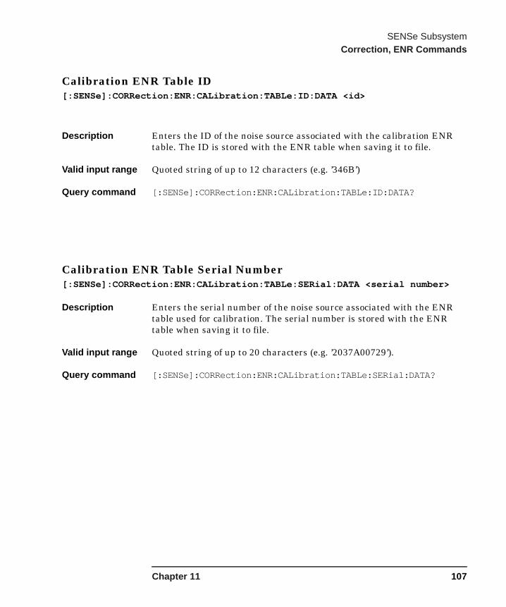
SENSe SubsystemCorrection, ENR Commands
Calibration ENR Table ID[:SENSe]:CORRection:ENR:CALibration:TABLe:ID:DATA <id>
Description Enters the ID of the noise source associated with the calibration ENR table. The ID is stored with the ENR table when saving it to file.
Valid input range Quoted string of up to 12 characters (e.g. ’346B’)
Query command [:SENSe]:CORRection:ENR:CALibration:TABLe:ID:DATA?
Calibration ENR Table Serial Number[:SENSe]:CORRection:ENR:CALibration:TABLe:SERial:DATA <serial number>
Description Enters the serial number of the noise source associated with the ENR table used for calibration. The serial number is stored with the ENR table when saving it to file.
Valid input range Quoted string of up to 20 characters (e.g. ’2037A00729’).
Query command [:SENSe]:CORRection:ENR:CALibration:TABLe:SERial:DATA?
Chapter 11 107

SENSe SubsystemCorrection, ENR Commands
Load Calibration ENR Table From SNS Noise Source[:SENSe]:CORRection:ENR:CALibration:TABLe:SNS
Description Causes the NFA to load ENR data into its calibration ENR table from the attached SNS noise source. Any measurement that is underway when the ENR data is loaded is restarted.
This command gives a settings conflict when no SNS noise source is connected.
Number of Entries in Calibration ENR Table[:SENSe]:CORRection:ENR:CALibration:TABLe:COUNt?
Description Returns the number of entries in the calibration ENR table.
Return value 0 to 81 entries
Query command [:SENSe]:CORRection:ENR:CALibration:TABLe:COUNt?
108 Chapter 11
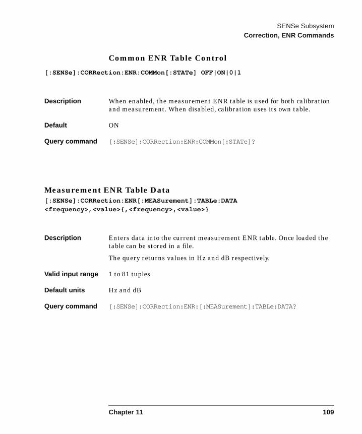
SENSe SubsystemCorrection, ENR Commands
Common ENR Table Control
[:SENSe]:CORRection:ENR:COMMon[:STATe] OFF|ON|0|1
Description When enabled, the measurement ENR table is used for both calibration and measurement. When disabled, calibration uses its own table.
Default ON
Query command [:SENSe]:CORRection:ENR:COMMon[:STATe]?
Measurement ENR Table Data[:SENSe]:CORRection:ENR[:MEASurement]:TABLe:DATA <frequency>,<value>{,<frequency>,<value>}
Description Enters data into the current measurement ENR table. Once loaded the table can be stored in a file.
The query returns values in Hz and dB respectively.
Valid input range 1 to 81 tuples
Default units Hz and dB
Query command [:SENSe]:CORRection:ENR:[:MEASurement]:TABLe:DATA?
Chapter 11 109

SENSe SubsystemCorrection, ENR Commands
Measurement ENR Table ID
[:SENSe]:CORRection:ENR[:MEASurement]:TABLe:ID:DATA <ID>
Description Enters the ID of the noise source associated with the measurement ENR table. The ID is stored with the ENR table when saving it to file.
Valid input range Quoted string of up to 12 characters (e.g. ’346B’).
Query command [:SENSe]:CORRection:ENR[:MEASurement]:TABLe:ID:DATA?
Measurement ENR Table Serial Number[:SENSe]:CORRection:ENR[:MEASurement]:TABLe:SERial:DATA <serial number>
Description Enters the serial number of the noise source associated with the measurement ENR table. The serial number is stored with the ENR table when saving it to file.
Valid input range Quoted string of up to 20 characters (e.g. ’2037A00729’)
Query command [:SENSe]:CORRection:ENR:[MEASurement]:TABLe:SERial:DATA?
110 Chapter 11

SENSe SubsystemCorrection, ENR Commands
Load Calibration ENR Table From SNS Noise Source
[:SENSe]:CORRection:ENR[:MEASurement]:TABLe:SNS
Description Causes the NFA to load ENR data into its measurement ENR table from the attached SNS. Any measurement that is underway when the ENR data is loaded is restarted.
This command gives a settings conflict when no SNS is connected.
Number Of Entries In calibration ENR Table[:SENSe]:CORRection:ENR[:MEASurement]:TABLe:COUNt?
Description Returns the number of entries in the measurement ENR table.
Return value 0 to 81
Query command [:SENSe]:CORRection:ENR[:MEASurement]:TABLe:COUNt?
Chapter 11 111
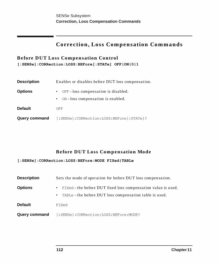
SENSe SubsystemCorrection, Loss Compensation Commands
Correction, Loss Compensation Commands
Before DUT Loss Compensation Control[:SENSe]:CORRection:LOSS:BEFore[:STATe] OFF|ON|0|1
Description Enables or disables before DUT loss compensation.
Options • OFF - loss compensation is disabled.
• ON - loss compensation is enabled.
Default OFF
Query command [:SENSe]:CORRection:LOSS:BEFore[:STATe]?
Before DUT Loss Compensation Mode
[:SENSe]:CORRection:LOSS:BEFore:MODE FIXed|TABLe
Description Sets the mode of operation for before DUT loss compensation.
Options • FIXed - the before DUT fixed loss compensation value is used.
• TABLe - the before DUT loss compensation table is used.
Default FIXed
Query command [:SENSe]:CORRection:LOSS:BEFore:MODE?
112 Chapter 11
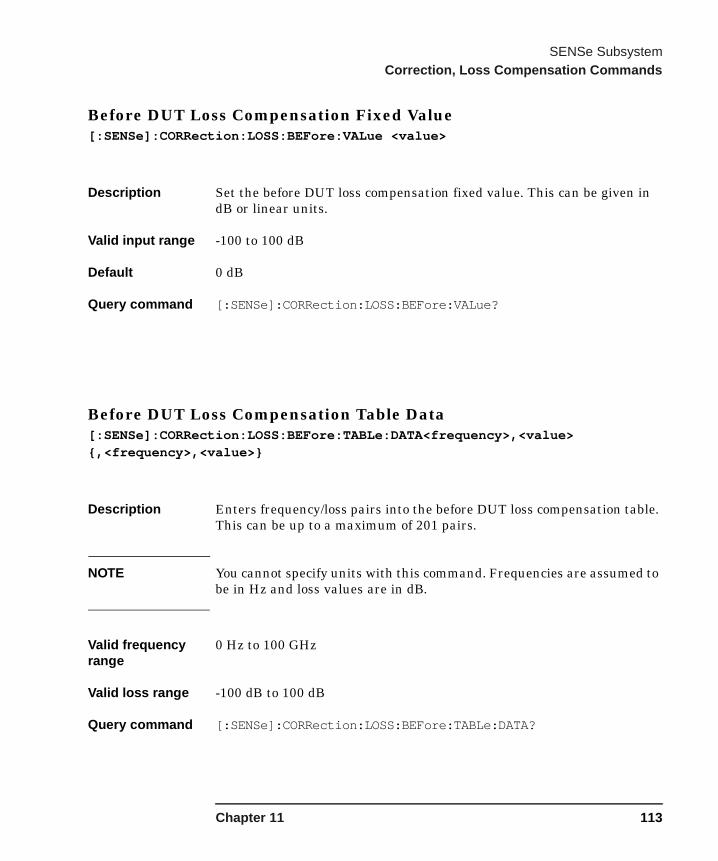
SENSe SubsystemCorrection, Loss Compensation Commands
Before DUT Loss Compensation Fixed Value[:SENSe]:CORRection:LOSS:BEFore:VALue <value>
Description Set the before DUT loss compensation fixed value. This can be given in dB or linear units.
Valid input range -100 to 100 dB
Default 0 dB
Query command [:SENSe]:CORRection:LOSS:BEFore:VALue?
Before DUT Loss Compensation Table Data[:SENSe]:CORRection:LOSS:BEFore:TABLe:DATA<frequency>,<value>{,<frequency>,<value>}
Description Enters frequency/loss pairs into the before DUT loss compensation table. This can be up to a maximum of 201 pairs.
NOTE You cannot specify units with this command. Frequencies are assumed to be in Hz and loss values are in dB.
Valid frequency range
0 Hz to 100 GHz
Valid loss range -100 dB to 100 dB
Query command [:SENSe]:CORRection:LOSS:BEFore:TABLe:DATA?
Chapter 11 113
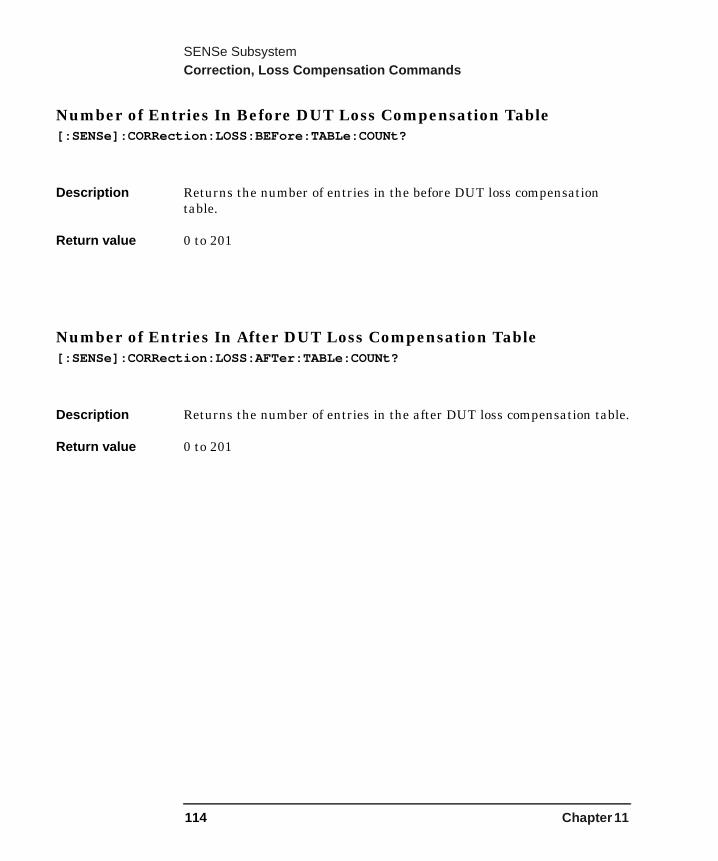
SENSe SubsystemCorrection, Loss Compensation Commands
Number of Entries In Before DUT Loss Compensation Table[:SENSe]:CORRection:LOSS:BEFore:TABLe:COUNt?
Description Returns the number of entries in the before DUT loss compensation table.
Return value 0 to 201
Number of Entries In After DUT Loss Compensation Table[:SENSe]:CORRection:LOSS:AFTer:TABLe:COUNt?
Description Returns the number of entries in the after DUT loss compensation table.
Return value 0 to 201
114 Chapter 11

SENSe SubsystemCorrection, Loss Compensation Commands
After DUT Loss Compensation Control
[:SENSe]:CORRection:LOSS:AFTer[:STATe] OFF|ON|0|1
Description Enables or disables after DUT loss compensation.
Options • OFF - loss compensation is disabled.
• ON - loss compensation is enabled.
Default OFF
Query command [:SENSe]:CORRection:LOSS:AFTer[:STATe]?
After DUT Loss Compensation Mode
[:SENSe]:CORRection:LOSS:AFTer:MODE FIXed|TABLe
Description Sets the mode of operation for after DUT loss compensation.
Options • FIXed - the after DUT fixed loss compensation value is used.
• TABLe - the after DUT loss compensation table is used.
Default FIXed
Query command [:SENSe]:CORRection:LOSS:AFTer:MODE?
Chapter 11 115
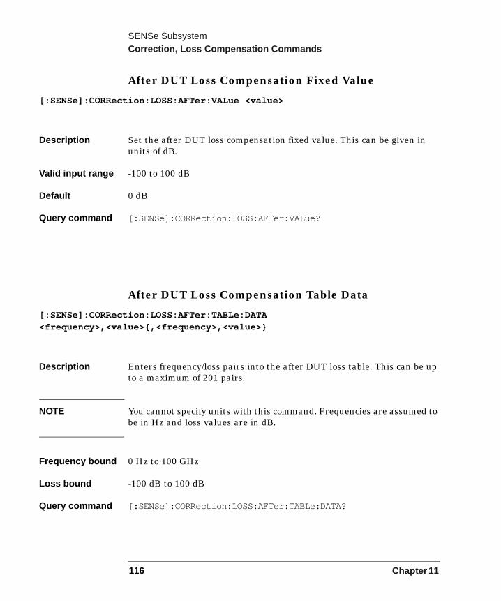
SENSe SubsystemCorrection, Loss Compensation Commands
After DUT Loss Compensation Fixed Value
[:SENSe]:CORRection:LOSS:AFTer:VALue <value>
Description Set the after DUT loss compensation fixed value. This can be given in units of dB.
Valid input range -100 to 100 dB
Default 0 dB
Query command [:SENSe]:CORRection:LOSS:AFTer:VALue?
After DUT Loss Compensation Table Data
[:SENSe]:CORRection:LOSS:AFTer:TABLe:DATA <frequency>,<value>{,<frequency>,<value>}
Description Enters frequency/loss pairs into the after DUT loss table. This can be up to a maximum of 201 pairs.
NOTE You cannot specify units with this command. Frequencies are assumed to be in Hz and loss values are in dB.
Frequency bound 0 Hz to 100 GHz
Loss bound -100 dB to 100 dB
Query command [:SENSe]:CORRection:LOSS:AFTer:TABLe:DATA?
116 Chapter 11

SENSe SubsystemCorrection, Loss Compensation Commands
Before DUT Temperature
[:SENSe]:CORRection:TEMPerature:BEFore <temperature>
Description Sets the before DUT temperature in units of Kelvin (K), degrees Celsius (CAL) or degrees Fahrenheit (FAR).
Valid input range 0K to 29650000K
Default 0K
Query command [:SENSe]:CORRection:TEMPerature:BEFore?
The query returns the value in K.
After DUT Temperature[:SENSe]:CORRection:TEMPerature:AFTer <temperature>
Description Sets the after DUT temperature in units of Kelvin (K), degrees Celsius (CAL) or degrees Fahrenheit (FAR).
Valid input range 0K to 29650000K
Default 0K
Query command [:SENSe]:CORRection:TEMPerature:AFTer?
The query returns the value in K.
Chapter 11 117

SENSe SubsystemCorrection, Calibration Commands
Correction, Calibration Commands
Initiate a User Calibration[:SENSe]:CORRection:COLLect[:ACQuire] STANdard
Description Initiates a user calibration.
118 Chapter 11

SENSe SubsystemCorrection, Tcold Commands
Correction, Tcold Commands
Automatically Read Tcold From SNS Noise Source[SENSe:]CORRection:TCOLd:SNS[:STATe] OFF|ON|0|1
Description When ON, the NFA periodically obtains Tcold values from the attached SNS noise source.
When OFF, either a user specified value or a the default is used.
This command is disabled when no SNS is connected and any attempt to set this command under these circumstances generates a settings conflict.
Query command [SENSe:]CORRection:TCOLd:SNS[:STATe] OFF|ON|0|1?
Set User Tcold Value From SNS Noise Source[SENSe:]CORRection:TCOLd:USER:SET
Description Reads a Tcold value from the attached SNS noise source and uses the value obtained the User Tcold value. See “User Tcold Value” on page 120.
This command is disabled when no SNS is connected. Any attempt to use this command under these circumstances generates a settings conflict.
Chapter 11 119
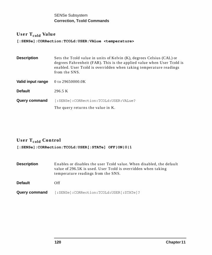
SENSe SubsystemCorrection, Tcold Commands
User Tcold Value[:SENSe]:CORRection:TCOLd:USER:VALue <temperature>
Description Sets the Tcold value in units of Kelvin (K), degrees Celsius (CAL) or degrees Fahrenheit (FAR). This is the applied value when User Tcold is enabled. User Tcold is overridden when taking temperature readings from the SNS.
Valid input range 0 to 29650000.0K
Default 296.5 K
Query command [:SENSe]:CORRection:TCOLd:USER:VALue?
The query returns the value in K.
User Tcold Control[:SENSe]:CORRection:TCOLd:USER[:STATe] OFF|ON|0|1
Description Enables or disables the user Tcold value. When disabled, the default value of 296.5K is used. User Tcold is overridden when taking temperature readings from the SNS.
Default Off
Query command [:SENSe]:CORRection:TCOLd:USER[:STATe]?
120 Chapter 11
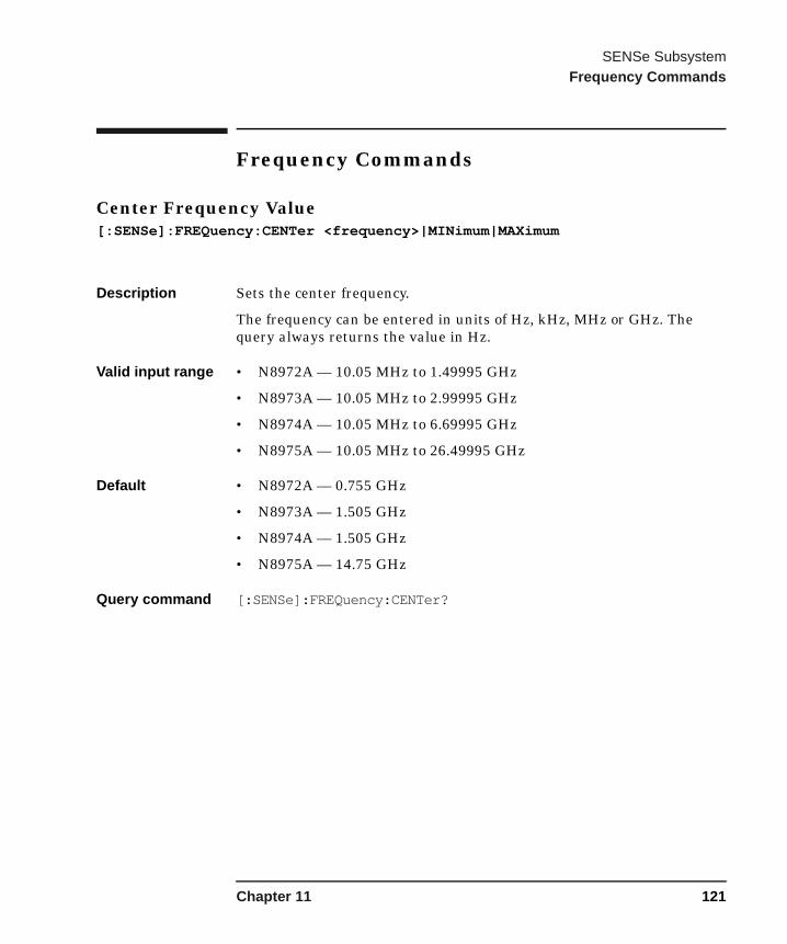
SENSe SubsystemFrequency Commands
Frequency Commands
Center Frequency Value[:SENSe]:FREQuency:CENTer <frequency>|MINimum|MAXimum
Description Sets the center frequency.
The frequency can be entered in units of Hz, kHz, MHz or GHz. The query always returns the value in Hz.
Valid input range • N8972A — 10.05 MHz to 1.49995 GHz
• N8973A — 10.05 MHz to 2.99995 GHz
• N8974A — 10.05 MHz to 6.69995 GHz
• N8975A — 10.05 MHz to 26.49995 GHz
Default • N8972A — 0.755 GHz
• N8973A — 1.505 GHz
• N8974A — 1.505 GHz
• N8975A — 14.75 GHz
Query command [:SENSe]:FREQuency:CENTer?
Chapter 11 121
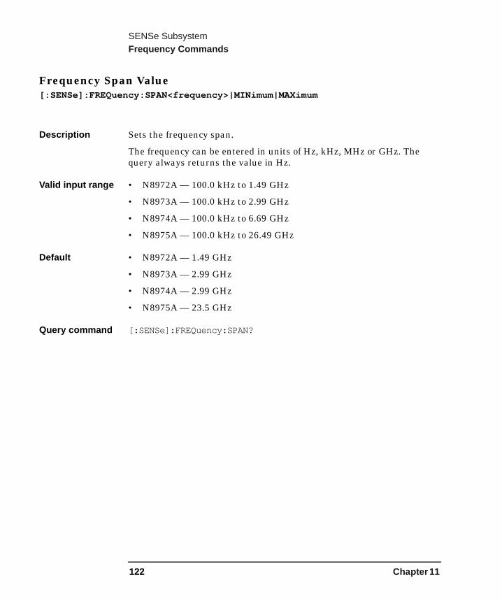
SENSe SubsystemFrequency Commands
Frequency Span Value[:SENSe]:FREQuency:SPAN<frequency>|MINimum|MAXimum
Description Sets the frequency span.
The frequency can be entered in units of Hz, kHz, MHz or GHz. The query always returns the value in Hz.
Valid input range • N8972A — 100.0 kHz to 1.49 GHz
• N8973A — 100.0 kHz to 2.99 GHz
• N8974A — 100.0 kHz to 6.69 GHz
• N8975A — 100.0 kHz to 26.49 GHz
Default • N8972A — 1.49 GHz
• N8973A — 2.99 GHz
• N8974A — 2.99 GHz
• N8975A — 23.5 GHz
Query command [:SENSe]:FREQuency:SPAN?
122 Chapter 11
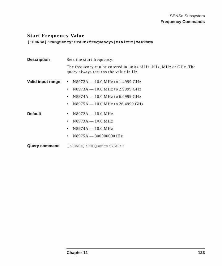
SENSe SubsystemFrequency Commands
Start Frequency Value[:SENSe]:FREQuency:STARt<frequency>|MINimum|MAXimum
Description Sets the start frequency.
The frequency can be entered in units of Hz, kHz, MHz or GHz. The query always returns the value in Hz.
Valid input range • N8972A — 10.0 MHz to 1.4999 GHz
• N8973A — 10.0 MHz to 2.9999 GHz
• N8974A — 10.0 MHz to 6.6999 GHz
• N8975A — 10.0 MHz to 26.4999 GHz
Default • N8972A — 10.0 MHz
• N8973A — 10.0 MHz
• N8974A — 10.0 MHz
• N8975A — 3000000001Hz
Query command [:SENSe]:FREQuency:STARt?
Chapter 11 123

SENSe SubsystemFrequency Commands
Stop Frequency Value[:SENSe]:FREQuency:STOP<frequency>|MINimum|MAXimum
Description Sets the sweep stop frequency.
The frequency can be entered in units of Hz, kHz, MHz or GHz. The query always returns the value in Hz.
Valid input range • N8972A — 10.1 MHz to 1.5 GHz
• N8973A — 10.1 MHz to 3.0 GHz
• N8974A — 10.1 MHz to 6.7 GHz
• N8975A — 10.1 MHz to 26.5 GHz
Default • N8972A — 1.50 GHz
• N8973A — 3.00 GHz
• N8974A — 3.00 GHz
• N8975A — 26.5 GHz
Query command [:SENSe]:FREQuency:STOP?
124 Chapter 11
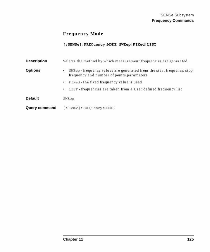
SENSe SubsystemFrequency Commands
Frequency Mode
[:SENSe]:FREQuency:MODE SWEep|FIXed|LIST
Description Selects the method by which measurement frequencies are generated.
Options • SWEep - frequency values are generated from the start frequency, stop frequency and number of points parameters
• FIXed - the fixed frequency value is used
• LIST - frequencies are taken from a User defined frequency list
Default SWEep
Query command [:SENSe]:FREQuency:MODE?
Chapter 11 125
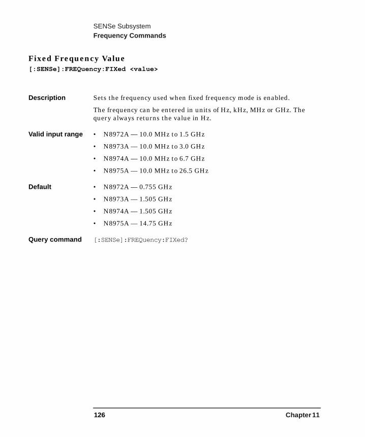
SENSe SubsystemFrequency Commands
Fixed Frequency Value[:SENSe]:FREQuency:FIXed <value>
Description Sets the frequency used when fixed frequency mode is enabled.
The frequency can be entered in units of Hz, kHz, MHz or GHz. The query always returns the value in Hz.
Valid input range • N8972A — 10.0 MHz to 1.5 GHz
• N8973A — 10.0 MHz to 3.0 GHz
• N8974A — 10.0 MHz to 6.7 GHz
• N8975A — 10.0 MHz to 26.5 GHz
Default • N8972A — 0.755 GHz
• N8973A — 1.505 GHz
• N8974A — 1.505 GHz
• N8975A — 14.75 GHz
Query command [:SENSe]:FREQuency:FIXed?
126 Chapter 11

SENSe SubsystemFrequency Commands
Frequency List Data
[:SENSe]:FREQuency:LIST:DATA <frequency>,<frequency>{,<frequency>}
Description Enters frequency values into the frequency table. The frequency table can hold up to 401 values and you must specify at least 2 values. Once loaded the table can be stored in a file.
You cannot specify units with this command and values are assumed to be Hz. The query returns values in Hz.
Valid input range 2 to 401 entries
Default units Hz
Query command [:SENSe]:FREQuency:LIST:DATA?
Number Of Entries In Frequency List[:SENSe]:FREQuency:LIST:COUNt?
Description Returns the number of entries in the frequency list.
Return value 0 to 401
Query command [:SENSe]:FREQency:LIST:COUNt?
Chapter 11 127

SENSe SubsystemSweep Commands
Sweep Commands
Number Of Points In Swept Measurement[:SENSe]:SWEep:POINts <number>
Description Sets the number of points in a sweep.
Valid input range 2 to 401
Default 11
Query command [:SENSe]:SWEep:POINts?
128 Chapter 11
SENSe SubsystemAveraging Commands
Averaging Commands
Average Number[:SENSe]:AVERage:COUNt <integer>
Description Specifies the number of times each measurement is sampled during averaging. If the count is 1 then no averaging is performed.
Valid input range 1 to 999
Default 1
Query command [:SENSe]:AVERage:COUNt?
Chapter 11 129
SENSe SubsystemAveraging Commands
Average Mode[:SENSe]:AVERage:MODE POINt|SWEep
Description Averaging can be carried out by either averaging each point within a sweep, or by averaging each point over successive sweeps.
NOTE This command is not available in the N8972A Noise Figure Analyzer.
Options • POINt - the selected number of averages are measured at each point before moving to the next point in the sweep. The masurement is complete after one sweep.
• SWEep - a single average is measured at each point in the sweep. The result at each point is built up by averaging the results of multiple sweeps until the selected number of averages have been measured at each point.
Default POINt
Query command [:SENSe]:AVERage:MODE?
130 Chapter 11
SENSe SubsystemAveraging Commands
Averaging Control[:SENSe]:AVERage[:STATe] OFF|ON|0|1
Description Enables or disables averaging.
Options • OFF or 0 - averaging is disabled
• ON or 1 - averaging is enabled
NOTE If averaging is enabled and the number of averages is set to 1, no averaging will take place.
Default OFF
Query command [:SENSe]:AVERage[:STATe]?
Chapter 11 131
SENSe SubsystemMeasurement Bandwidth Commands
Measurement Bandwidth Commands
Measurement Bandwidth[:SENSe]:BANDwidth|BWIDth[:RESolution]100kHz|200kHz|400kHz|1MHz|2MHz|4MHz
Description Specifies the measurement bandwidth.
NOTE This command is not available in the N8972A Noise Figure Analyzer.
Default 4MHz
Query command [:SENSe]:BANDwidth|BWIDth[:RESolution]?
132 Chapter 11

SENSe SubsystemManual Measurement Commands
Manual Measurement Commands
Accept Manual Measurement Reading[:SENSe]:MANual:ACCept
Description Used to inform the NFA that the reading is settled and the current hot or cold power can be stored.
This command gives a settings conflict when manual measurement mode is OFF.
Manual Measurement Calibration Control[:SENSe]:MANual:CALibration[:STATe] OFF|ON|0|1
Description When ON calibration is performed, and when OFF measurement is performed.
This command gives a settings conflict when manual measurement mode is OFF.
Default Off
Reset Off
Query command [:SENSe]:MANual:CALibration[:STATe]?
Chapter 11 133

SENSe SubsystemManual Measurement Commands
Manual Measurement IF Mode[:SENSe]:MANual:IF:MODE AUTO|HOLD|FIXed
Description Used to control the IF attenuator setting as follows:
• When set to AUTO, the IF attenuator auto-ranging is enabled.
• When set to HOLD, the current IF attenuator setting is held until the selection is changed.
• When set to FIXed, the value specified in IF Attenuator Fixed Value is used.
Query command [:SENSe]:MANual:IF:MODE?
Default Auto
134 Chapter 11
SENSe SubsystemManual Measurement Commands
Manual Measurement RF Mode[:SENSe]:MANual:RF:MODE AUTO|HOLD|FIXed
NOTE Microwave attenuators are not applicable to N8972A and N8973A models of NFA.
Description Used to control the RF and microwave attenuator setting as follows:
• when set to AUTO, the RF (or microwave) attenuator auto-ranging is enabled
• when set to HOLD, the current RF attenuator setting is held until the selection is changed
• when set to FIXed, one of the values specified in RF Attenuator Fixed Value or Microwave Attenuator Fixed Value
Default Auto
Query command [:SENSe]:MANual:RF:MODE?
Chapter 11 135

SENSe SubsystemManual Measurement Commands
Manual Measurement Control
[:SENSe]:MANual[:STATe] OFF|ON|0|1
Description Enables and disables Manual Measurement Mode.
When set to ON, the steps required to make a measrement are controlled by the other manual measurement commands.
When set to OFF, all manual measurement remote commands give a settings conflict.
Default Off
Query command [:SENSe]:MANual[STATe]?
Manual Measurement Point Select[:SENSe]:MANual:POINt <integer>
Description Allows the user to specify the measurement point at which to make the manual measurement. The point referred to is that derived from the sweep points and frequency settings. This item is not applicable when fixed frequency is selected as this selection, or manual measurement mode being OFF, causes a settings conflict.
Range Lower bound is 1 while the upper bound is dependant on the number of measurement points.
Default 1
Query command [:SENSe]:MANual:POINt?
136 Chapter 11

SENSe SubsystemManual Measurement Commands
Manual Measurement Power Query
[:SENSe]:MANual:POWer[:LEVel]?
Description Read the current Phot or Pcold value.
Comparing successive results allows you to determine whether the manual power result is a Phot or a Pcold reading.
This command gives a settings conflict when manual measurement mode is OFF.
Query command [:SENSe]:MANual:POWer[:LEVel]?
Manual Measurement Fixed RF Attenuator Value[:SENSe]:MANual:RF:FIXed <ampl>
Description Allows you to specify the fixed RF attenuator setting in dB. The specified value is applied when the RF/Microwave Attenuator Control is set to FIXed and the frequency is less than or equal to 3 GHz.
Valid input range 0 to 40 dB in steps of 5 dB
Default 0 dB
Query command [:SENSe]:MANual:RF:FIXed?
Chapter 11 137
SENSe SubsystemManual Measurement Commands
Manual Measurement Fixed Microwave Attenuator Value[:SENSe]:MANual:MWAVe:FIXed <ampl>
NOTE Microwave attenuators are not applicable to N8972A and N8973A models of NFA.
Description Allows you to specify the fixed microwave attenuator setting. The specified value is applied when FIXed is set and the frequency is above 3 GHz.
Valid input range 0 to 30 dB in steps of 15 dB
Default 0 dB
Query command [:SENSe]:MANual:MWAVe:FIXed?
Manual Measurement Fixed IF Attenuator Value[:SENSe]:MANual:IF:FIXed <ampl>
Description Allows you to specify the fixed IF attenuator setting. When FIXed is set the specified value is applied.
Valid input range 0 to 70 dB
Default 59 dB
Query command [:SENSe]:MANual:IF:FIXed?
138 Chapter 11
12 SOURce Subsystem
The SOURce Subsystem allows you to select the type of noise source used.
139
SOURce SubsystemSource Commands
Source Commands
Noise Source Preference
SOURce:NOISe[:PREFerence] NORMal|SNS
Description A NORMAL noise source and a SNS noise source can both be connected to the NFA at the same time. The NFA can only drive one of these sources at any one time. This function allows you to specify which noise source to use.
When set to NORMAL the BNC Noise Source Drive Output is used.
This command gives a settings conflict when no SNS is connected.
Options • NORMal — selects the normal noise source.• SNS — selects the SNS noise source if attached, otherwise the normal
noise source is used.
Query command SOURce:NOISe[:PREFerence]?
140 Chapter 12

13 STATus Subsystem
The STATus subsystem controls the SCPI defined status register hierarchy. For details on the NFA status registers, see Appendix B , “NFA Status Registers,” on page 233.
141
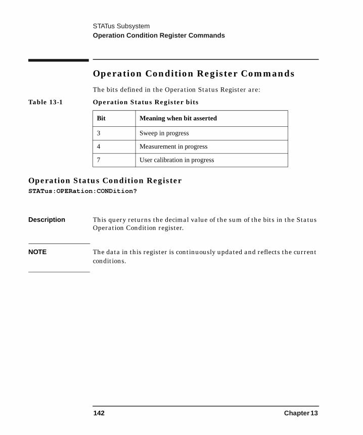
STATus SubsystemOperation Condition Register Commands
Operation Condition Register Commands
The bits defined in the Operation Status Register are:
Operation Status Condition RegisterSTATus:OPERation:CONDition?
Description This query returns the decimal value of the sum of the bits in the Status Operation Condition register.
NOTE The data in this register is continuously updated and reflects the current conditions.
Table 13-1 Operation Status Register bits
Bit Meaning when bit asserted
3 Sweep in progress
4 Measurement in progress
7 User calibration in progress
142 Chapter 13
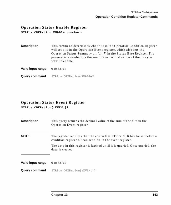
STATus SubsystemOperation Condition Register Commands
Operation Status Enable RegisterSTATus:OPERation:ENABle <number>
Description This command determines what bits in the Operation Condition Register will set bits in the Operation Event register, which also sets the Operation Status Summary bit (bit 7) in the Status Byte Register. The parameter <number> is the sum of the decimal values of the bits you want to enable.
Valid input range 0 to 32767
Query command STATus:OPERation:ENABle?
Operation Status Event RegisterSTATus:OPERation[:EVENt]?
Description This query returns the decimal value of the sum of the bits in the Operation Event register.
NOTE The register requires that the equivalent PTR or NTR bits be set before a condition register bit can set a bit in the event register.
The data in this register is latched until it is queried. Once queried, the data is cleared.
Valid input range 0 to 32767
Query command STATus:OPERation[:EVENt]?
Chapter 13 143
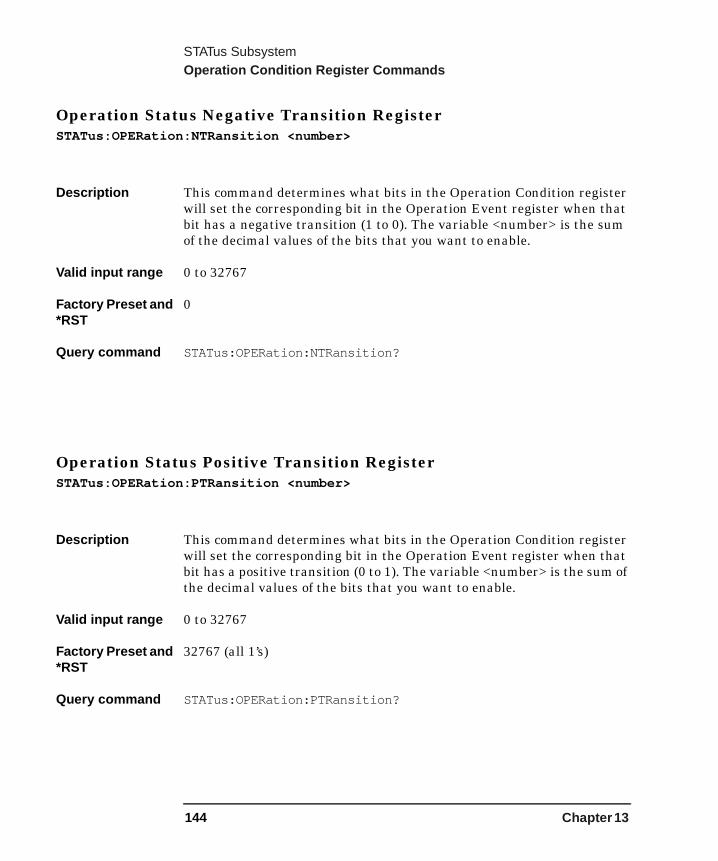
STATus SubsystemOperation Condition Register Commands
Operation Status Negative Transition RegisterSTATus:OPERation:NTRansition <number>
Description This command determines what bits in the Operation Condition register will set the corresponding bit in the Operation Event register when that bit has a negative transition (1 to 0). The variable <number> is the sum of the decimal values of the bits that you want to enable.
Valid input range 0 to 32767
Factory Preset and *RST
0
Query command STATus:OPERation:NTRansition?
Operation Status Positive Transition RegisterSTATus:OPERation:PTRansition <number>
Description This command determines what bits in the Operation Condition register will set the corresponding bit in the Operation Event register when that bit has a positive transition (0 to 1). The variable <number> is the sum of the decimal values of the bits that you want to enable.
Valid input range 0 to 32767
Factory Preset and *RST
32767 (all 1’s)
Query command STATus:OPERation:PTRansition?
144 Chapter 13

STATus SubsystemQuestionable Correction Status Register
Questionable Correction Status RegisterThe bits defined in the Questionable Correction Status register are:
Questionable Correction Condition RegisterSTATus:QUEStionable:CORRection:CONDition?
Description This query returns the decimal value of the sum of the bits in the Questionable Correction Condition register.
NOTE The data in this register is continuously updated and reflects the current conditions.
Table 13-2 Questionable Correction Status Register bits
Bit Meaning when bit asserted
0 User calibration required
1 User calibration failed
2 Uncorrected measurement data
3 User calibration interpolated
Chapter 13 145

STATus SubsystemQuestionable Correction Status Register
Questionable Correction Enable RegisterSTATus:QUEStionable:CORRection:ENABle <number>
Description This command determines what bits in the Questionable Correction Condition Register will set bits in the Questionable Correction Event register, which also sets the Correction Summary bit (bit 10) in the Questionable Status Register. The variable <number> is the sum of the decimal values of the bits you want to enable.
Valid input range 0 to 32767
Factory Preset and *RST
32767 (all 1’s)
Query command STATus:QUEStionable:CORRection:ENABle?
Questionable Correction Event RegisterSTATus:QUEStionable:CORRection[:EVENt]?
Description This query returns the decimal value of the sum of the bits in the Questionable Correction Event register.
NOTE The register requires that the equivalent PTR or NTR bits be set before a condition register bit can set a bit in the event register.
The data in this register is latched until it is queried. Once queried, the data is cleared.
146 Chapter 13

STATus SubsystemQuestionable Correction Status Register
Questionable Correction Negative Transition RegisterSTATus:QUEStionable:CORRection:NTRansition <number>
Description This command determines what bits in the Questionable Correction Condition register will set the corresponding bit in the Questionable Correction Event register when that bit has a negative transition (1 to 0). The variable <number> is the sum of the decimal values of the bits that you want to enable.
Valid input range 0 to 32767
Factory Preset and *RST
0
Query command STATus:QUEStionable:CORRection:NTRansition?
Questionable Correction Positive Transition RegisterSTATus:QUEStionable:CORRection:PTRansition <number>
Description This command determines what bits in the Questionable Correction Condition register will set the corresponding bit in the Questionable Correction Event register when that bit has a positive transition (0 to 1). The variable <number> is the sum of the decimal values of the bits that you want to enable.
Valid input range 0 to 32767
Factory Preset and *RST
32767 (all 1’s)
Query command STATus:QUEStionable:CORRection:PTRansition?
Chapter 13 147
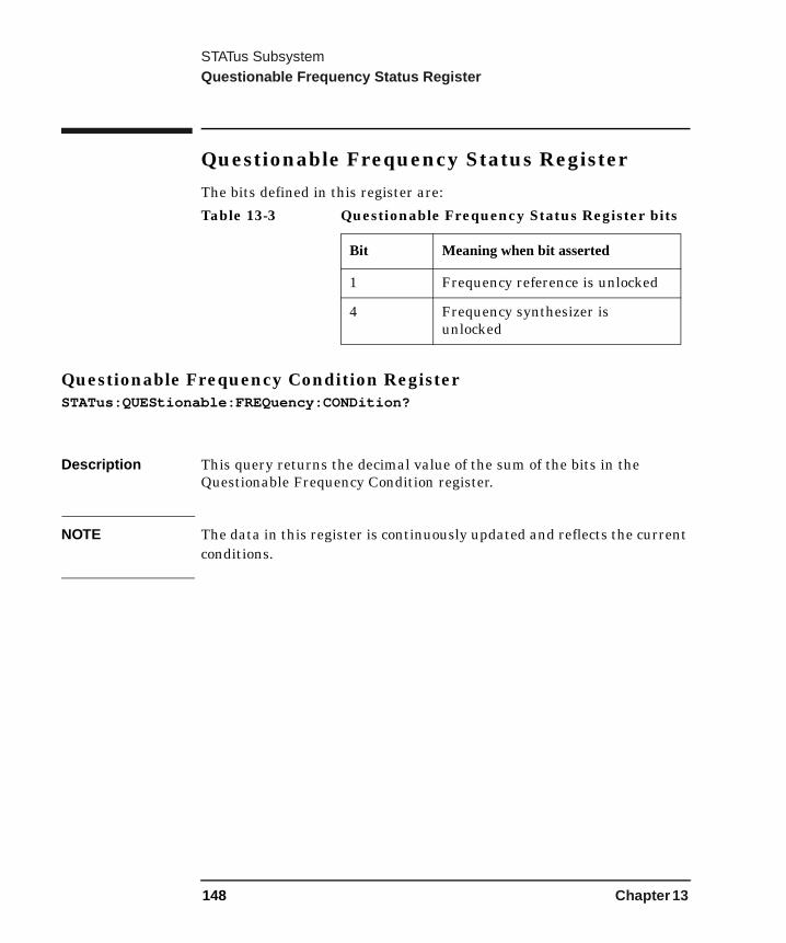
STATus SubsystemQuestionable Frequency Status Register
Questionable Frequency Status RegisterThe bits defined in this register are:
Questionable Frequency Condition RegisterSTATus:QUEStionable:FREQuency:CONDition?
Description This query returns the decimal value of the sum of the bits in the Questionable Frequency Condition register.
NOTE The data in this register is continuously updated and reflects the current conditions.
Table 13-3 Questionable Frequency Status Register bits
Bit Meaning when bit asserted
1 Frequency reference is unlocked
4 Frequency synthesizer is unlocked
148 Chapter 13

STATus SubsystemQuestionable Frequency Status Register
Questionable Frequency Enable RegisterSTATus:QUEStionable:FREQuency:ENABle <number>
Description This command determines what bits in the Questionable Frequency Condition Register will set bits in the Questionable Frequency Event register, which also sets the Frequency Summary bit (bit 5) in the Questionable Status Register. The variable <number> is the sum of the decimal values of the bits you want to enable.
Factory Preset and *RST
32767 (all 1’s)
Query command STATus:QUEStionable:FREQuency:ENABle?
Questionable Frequency Event RegisterSTATus:QUEStionable:FREQuency[:EVENt]?
Description This query returns the decimal value of the sum of the bits in the Questionable Frequency Event register.
NOTE The register requires that the equivalent PTR or NTR bits be set before a condition register bit can set a bit in the event register.
The data in this register is latched until it is queried. Once queried, the data is cleared.
Chapter 13 149

STATus SubsystemQuestionable Frequency Status Register
Questionable Frequency Negative Transition RegisterSTATus:QUEStionable:FREQuency:NTRansition <number>
Description This command determines what bits in the Questionable Frequency Condition register will set the corresponding bit in the Questionable Frequency Event register when that bit has a negative transition (1 to 0).
The variable <number> is the sum of the decimal values of the bits that you want to enable.
Factory Preset and *RST
0
Query command STATus:QUEStionable:FREQuency:NTRansition?
Questionable Frequency Positive Transition RegisterSTATus:QUEStionable:FREQuency:PTRansition <number>
Description This command determines what bits in the Questionable Frequency Condition register will set the corresponding bit in the Questionable Frequency Event register when that bit has a positive transition (0 to 1).
The variable <number> is the sum of the decimal values of the bits that you want to enable.
Factory Preset and *RST
32767 (all 1’s)
Query command STATus:QUEStionable:FREQuency:PTRansition?
150 Chapter 13

STATus SubsystemQuestionable Status Register
Questionable Status Register
The bits defined in the Questionable Status Register are:
Questionable Status Condition RegisterSTATus:QUEStionable:CONDition?
Description This query returns the decimal value of the sum of the bits in the Questionable Status Condition register.
NOTE The data in this register is continuously updated and reflects the current conditions.
Table 13-4 Questionable Status Register bits
Bit Meaning when bit asserted
5 Questionable Frequency Event Register bit(s) set
9 Questionable Integrity Event Register bit(s) set
10 Questionable Correction Event Register bit(s) set
Chapter 13 151

STATus SubsystemQuestionable Status Register
Questionable Status Enable Register
STATus:QUEStionable:ENABle <number>
Description This command determines what bits in the Questionable Status Condition Register will set bits in the Questionable Status Event register, which also sets the Questionable Status Summary bit (bit3) in the Status Byte Register. The variable <number> is the sum of the decimal values of the bits you want to enable.
NOTE The preset condition is to have all bits in this enable register set to 0. To have any Questionable Events reported to the Status Byte Register, 1 or more bits need to be set to 1. It is recommended that all bits be enabled in this register. The Status Byte Event Register should be queried after each measurement to check the Questionable Status Summary (bit 3). If it is equal to 1, there was some kind of condition during the test, that might make the test results invalid. If it is equal to 0, this indicates that no hardware problem, or measurement problem was detected by the analyzer that affected the result.
Valid input range 0 to 32767
Factory Preset and *RST:
0
Query command STATus:QUEStionable:ENABle?
152 Chapter 13

STATus SubsystemQuestionable Status Register
Questionable Status Event RegisterSTATus:QUEStionable[:EVENt]?
Description This query returns the decimal value of the sum of the bits in the Questionable Status Event register.
NOTE The register requires that the equivalent PTR or NTR bits be set before a condition register bit can set a bit in the event register.
The data in this register is latched until it is queried. Once queried, the data is cleared.
Questionable Status Negative Transition RegisterSTATus:QUEStionable:NTRansition <number>
NOTE This command determines what bits in the Questionable Status Condition register will set the corresponding bit in the Questionable Status Event register when that bit has a negative transition (1 to 0). The variable <number> is the sum of the decimal values of the bits that you want to enable.
Valid input range 0 to 32767
Factory Preset and *RST
0
Query command STATus:QUEStionable:NTRansition?
Chapter 13 153
STATus SubsystemQuestionable Status Register
Questionable Status Positive Transition RegisterSTATus:QUEStionable:PTRansition <number>
Description This command determines what bits in the Questionable Status Condition register will set the corresponding bit in the Questionable Status Event register when that bit has a positive transition (0 to 1). The variable <number> is the sum of the decimal values of the bits that you want to enable.
Valid input range 0 to 32767
Factory Presetand *RST:
32767 (all 1’s)
Query command STATus:QUEStionable:PTRansition?
154 Chapter 13
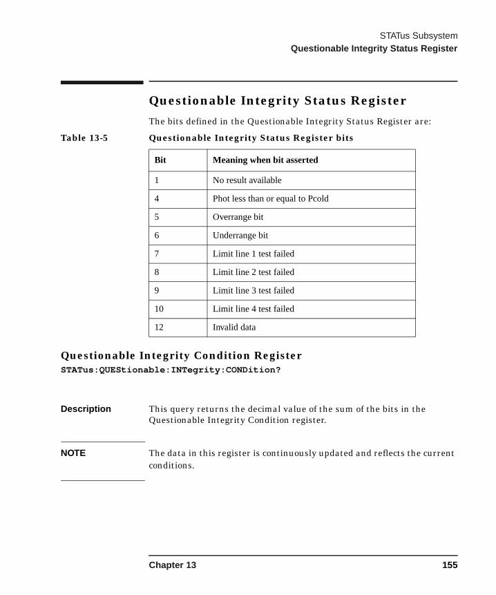
STATus SubsystemQuestionable Integrity Status Register
Questionable Integrity Status RegisterThe bits defined in the Questionable Integrity Status Register are:
Questionable Integrity Condition RegisterSTATus:QUEStionable:INTegrity:CONDition?
Description This query returns the decimal value of the sum of the bits in the Questionable Integrity Condition register.
NOTE The data in this register is continuously updated and reflects the current conditions.
Table 13-5 Questionable Integrity Status Register bits
Bit Meaning when bit asserted
1 No result available
4 Phot less than or equal to Pcold
5 Overrange bit
6 Underrange bit
7 Limit line 1 test failed
8 Limit line 2 test failed
9 Limit line 3 test failed
10 Limit line 4 test failed
12 Invalid data
Chapter 13 155

STATus SubsystemQuestionable Integrity Status Register
Questionable Integrity Enable RegisterSTATus:QUEStionable:INTegrity:ENABle <number>
Description This command determines what bits in the Questionable Integrity Condition Register will set bits in the Questionable Integrity Event register, which also sets the Integrity Summary bit (bit 9) in the Questionable Register. The variable <number> is the sum of the decimal values of the bits you want to enable.
Valid input range 0 to 32767
Factory Preset and *RST
32767 (all 1’s)
Query command STATus:QUEStionable:INTegrity:ENABle?
Questionable Integrity Event RegisterSTATus:QUEStionable:INTegrity[:EVENt]?
Description This query returns the decimal value of the sum of the bits in the Questionable Integrity Event register.
NOTE The register requires that the equivalent PTR or NTR bits be set before a condition register bit can set a bit in the event register.
The data in this register is latched until it is queried. Once queried, the data is cleared.
156 Chapter 13
STATus SubsystemQuestionable Integrity Status Register
Questionable Integrity Negative Transition RegisterSTATus:QUEStionable:INTegrity:NTRansition <number>
Description This command determines what bits in the Questionable Integrity Condition register will set the corresponding bit in the Questionable Integrity Event register when that bit has a negative transition (1 to 0) The variable <number> is the sum of the decimal values of the bits that you want to enable.
Valid input range 0 to 32767
Factory Preset and *RST
0
Query command STATus:QUEStionable:INTegrity:NTRansition?
Questionable Integrity Positive Transition RegisterSTATus:QUEStionable:INTegrity:PTRansition <number>
Description This command determines what bits in the Questionable Integrity Condition register will set the corresponding bit in the Questionable Integrity Event register when that bit has a positive transition (0 to 1) The variable <number> is the sum of the decimal values of the bits that you want to enable.
Valid input range 0 to 32767
Factory Preset and *RST
0
Query command STATus:QUEStionable:INTegrity:PTRansition?
Chapter 13 157

STATus SubsystemStatus Preset
Status Preset
Status PresetSTATus:PRESet
Description Sets bits in the enable and transition registers to their default state. It presets all the Transition Filters, Enable Registers, and the Error/Event Queue Enable. It has no effect on Event Registers, Error/Event QUEue, IEEE 488.2 ESE, and SRE Registers.
158 Chapter 13
14 SYSTem Subsystem
The SYSTem Subsystem sets the controls and parameters associated with overall system communication. These functions are not related to instrument performance. Examples include functions for performing general housekeeping and global configuration settings.
159
SYSTem SubsystemExternal LO Control
External LO Control
External LO controlSYSTem:CONFigure:LOSCillator:CONTrol[:STATe] OFF|ON|0|1
Description Enables or disables external LO control.
Default 0
Query command SYSTem:CONFigure:LOSCillator:CONTrol[:STATe]?
External LO TypeSYSTem:CONFigure:LOSCillator:TYPE SCPI|CUSTom
Description Selects whether the LO is a SCPI device or it requires a custom setup.
Default SCPI
Query command SYSTem:CONFigure:LOSCillator:TYPE?
160 Chapter 14

SYSTem SubsystemExternal LO Control
External LO Auxiliary CommandSYSTem:CONFigure:LOSCillator:COMMand:AUXiliary ’<command> ’
Description Defines the LO auxiliary command.
Valid input range Quoted string of up to 79 characters
Default ’OUTP:STAT ON’
Query command SYSTem:CONFigure:LOSCillator:COMMand:AUXiliary?
External LO Frequency PrefixSYSTem:CONFigure:LOSCillator:COMMand:FREQuency:PREFix ’<prefix>’
Description Defines the LO frequency command where the prefix precedes the frequency value to be sent to the LO.
Valid input range Quoted string of up to 79 characters
Default ’FREQ’
Query command SYSTem:CONFigure:LOSCillator:COMMand:FREQuency:PREFix?
Chapter 14 161
SYSTem SubsystemExternal LO Control
External LO Frequency Suffix
SYSTem:CONFigure:LOSCillator:COMMand:FREQuency:SUFFix ’<suffix>’
Description Defines the LO frequency command where the suffix is appended to the frequency value to be sent to the LO.
Valid input range Quoted string of up to 79 characters
Default ’ HZ’
Query command SYSTem:CONFigure:LOSCillator:COMMand:FREQuency:SUFFix?
External LO Power PrefixSYSTem:CONFigure:LOSCillator:COMMand:POWer:PREFix ’<prefix>’ ’
Description Defines the LO power command prefix where the prefix precedes the power value to be sent to the LO.
Valid input range Quoted string of up to 79 characters
Default ’POW’
Query command SYSTem:CONFigure:LOSCillator:COMMand:POWer:PREFix?
162 Chapter 14
SYSTem SubsystemExternal LO Control
External LO Power Suffix
SYSTem:CONFigure:LOSCillator:COMMand:POWer:SUFFix ’<suffix>’
Description Defines the LO power command suffix where the suffix is appended to the power value to be sent to the LO.
Valid input range Quoted string of up to 79 characters
Default ’ DBM’
Query command SYSTem:CONFigure:LOSCillator:COMMand:POWer:SUFFix?
External LO Maximum FrequencySYSTem:CONFigure:LOSCillator:PARameter:MAXimum[:FREQuency] <frequency>
Description Defines the maximum LO frequency.
The value can be given in units of Hz, kHz, MHz or GHz.
Valid input range 10.001 kHz to 300 GHz
Default 40.0 GHz
Query command SYSTem:CONFigure:LOSCillator:PARameter:MAXimum[:FREQuency]?
The query always returns the value in Hz.
Chapter 14 163

SYSTem SubsystemExternal LO Control
External LO Minimum Frequency
SYSTem:CONFigure:LOSCillator:PARameter:MINimum[:FREQuency] <frequency>
Description Defines the minimum LO frequency. The value can be given in units of Hz, kHz, MHz or GHz.
Valid input range 1 Hz to 299.99999 GHz
Default 10.0 MHz
Query command SYSTem:CONFigure:LOSCillator:PARameter:MINimum[:FREQuency]?
The query always returns the value in Hz.
External LO Power LevelSYSTem:CONFigure:LOSCillator:PARameter:POWer[:LEVel] <ampl>
Description Defines the LO power level in dBm.
Valid input range -100 dBm to 100 dBm
Default 0.0 dBm
Query command SYSTem:CONFigure:LOSCillator:PARameter:POWer[:LEVel]?
164 Chapter 14
SYSTem SubsystemExternal LO Control
External LO Settling Time
SYSTem:CONFigure:LOSCillator:PARameter:SETTling[:TIME] <time>
Description Defines the LO settling time in seconds.
Valid input range 0 to 100 seconds
Default 100.0 milliseconds
Query command SYSTem:CONFigure:LOSCillator:PARameter:SETTling[:TIMe]?
External LO MultiplierSYSTem:CONFigure:LOSCillator:PARameter:MULTiplier <integer>
Description Defines the LO frequency multiplier value.
Valid input range Integer, 1 to 1000000000
Default 1
Query command SYSTem:CONFigure:LOSCillator:PARameter:MULTiplier?
Chapter 14 165
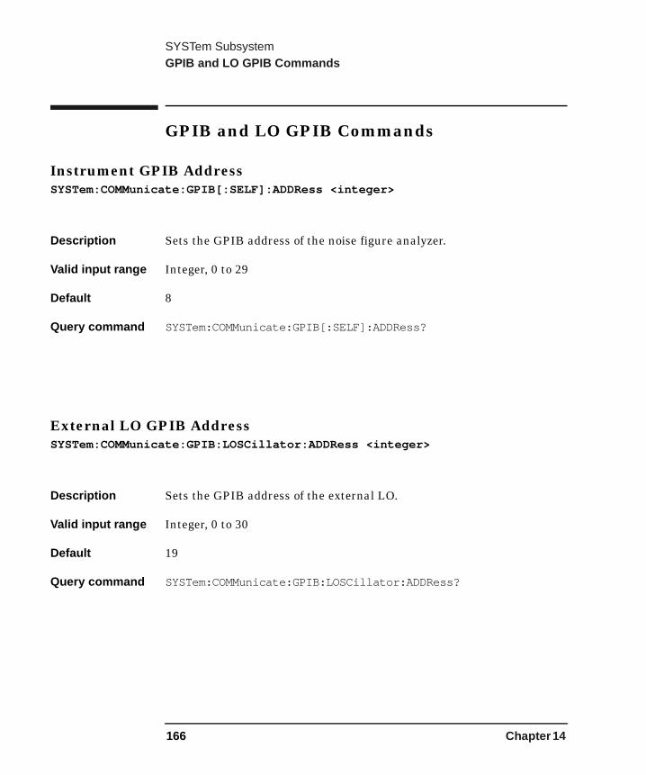
SYSTem SubsystemGPIB and LO GPIB Commands
GPIB and LO GPIB Commands
Instrument GPIB AddressSYSTem:COMMunicate:GPIB[:SELF]:ADDRess <integer>
Description Sets the GPIB address of the noise figure analyzer.
Valid input range Integer, 0 to 29
Default 8
Query command SYSTem:COMMunicate:GPIB[:SELF]:ADDRess?
External LO GPIB AddressSYSTem:COMMunicate:GPIB:LOSCillator:ADDRess <integer>
Description Sets the GPIB address of the external LO.
Valid input range Integer, 0 to 30
Default 19
Query command SYSTem:COMMunicate:GPIB:LOSCillator:ADDRess?
166 Chapter 14
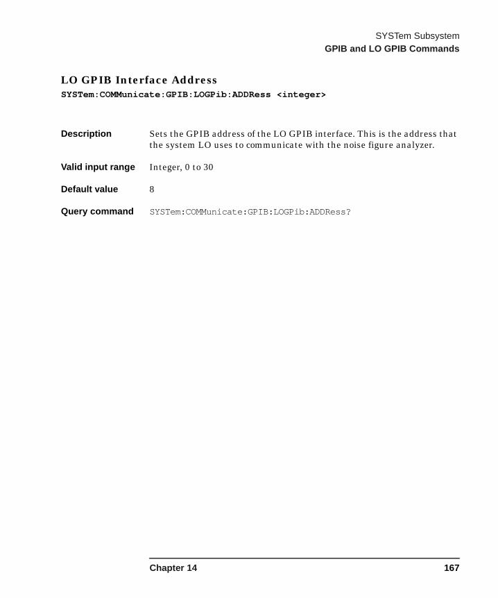
SYSTem SubsystemGPIB and LO GPIB Commands
LO GPIB Interface AddressSYSTem:COMMunicate:GPIB:LOGPib:ADDRess <integer>
Description Sets the GPIB address of the LO GPIB interface. This is the address that the system LO uses to communicate with the noise figure analyzer.
Valid input range Integer, 0 to 30
Default value 8
Query command SYSTem:COMMunicate:GPIB:LOGPib:ADDRess?
Chapter 14 167
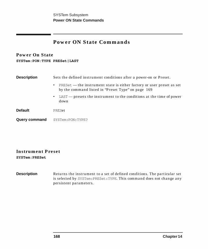
SYSTem SubsystemPower ON State Commands
Power ON State Commands
Power On StateSYSTem:PON:TYPE PRESet|LAST
Description Sets the defined instrument conditions after a power-on or Preset.
• PRESet — the instrument state is either factory or user preset as set by the command listed in “Preset Type” on page 169
• LAST — presets the instrument to the conditions at the time of power down
Default PRESet
Query command SYSTem:PON:TYPE?
Instrument PresetSYSTem:PRESet
Description Returns the instrument to a set of defined conditions. The particular set is selected by SYSTem:PRESet:TYPE. This command does not change any persistent parameters.
168 Chapter 14
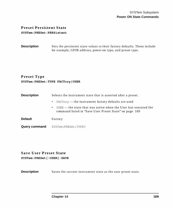
SYSTem SubsystemPower ON State Commands
Preset Persistent StateSYSTem:PRESet:PERSistent
Description Sets the persistent state values to their factory defaults. These include for example, GPIB address, power-on type, and preset type.
Preset TypeSYSTem:PRESet:TYPE FACTory|USER
Description Selects the instrument state that is asserted after a preset.
• FACTory — the instrument factory defaults are used
• USER — the state that was active when the User last executed the command listed in “Save User Preset State” on page 169
Default Factory
Query command SYSTem:PRESet:TYPE?
Save User Preset StateSYSTem:PRESet[:USER]:SAVE
Description Saves the current instrument state as the user preset state.
Chapter 14 169
SYSTem SubsystemPower ON State Commands
Time Since Instrument Was Switched OnSYSTem:PON:TIME?
Description Returns the number of seconds since the instrument was last powered on.
Time Since Instrument Was Switched On For First TimeSYSTem:PON:ETIMe?
Description Returns the number of seconds since the instrument was powered on for the very first time.
170 Chapter 14
SYSTem SubsystemRemote Interface Command
Remote Interface Command
Communication Port SelectSYSTem:COMMunicate:PORT GPIB|SERial
Description Sets the remote interface communications port.
NOTE The settings take effect after the next power cycle (instrument power off, then power on).
Default value GPIB
Query command SYSTem:COMMunicate:PORT?
Chapter 14 171

SYSTem SubsystemSerial Port Commands
Serial Port Commands
Serial Port DTR ControlSYSTem:COMMunicate:SERial:CONTrol:DTR OFF|ON|IBFull
Description Controls the serial port DTR line.
Command options • OFF - DTR is de-asserted (i.e. disable serial port)
• ON - DTR is asserted - (i.e. enable serial port)
• IBFull - DTR is used for receive data pacing
Default OFF
Query command SYSTem:COMMunicate:SERial:CONTrol:DTR?
Serial Port RTS ControlSYSTem:COMMunicate:SERial:CONTrol:RTS OFF|ON|IBFull
Description Controls the serial port RTS line.
Command options • OFF — RTS is de-asserted (i.e. no transmission pending).
• ON — RTS is asserted (i.e. transmission pending).
• IBFull — RTS is used for receive data pacing.
Default OFF
Query command SYSTem:COMMunicate:SERial:CONTrol:RTS?
172 Chapter 14

SYSTem SubsystemSerial Port Commands
Serial Port Baud RateSYSTem:COMMunicate:SERial[:RECeive]:BAUD <integer>
Description Specifies the serial port baud rate
Valid input 1200|2400|4800|9600|19200|38400
Default 9600
Query command SYSTem:COMMunicate:SERial[:RECeive]:BAUD?
Serial Port Receive PacingSYSTem:COMMunicate:SERial[:RECeive]:PACE XON|NONE
Description Enable or disable XON/XOFF receive pacing.
Default Persistent State with factory default XON
Query command SYSTem:COMMunicate:SERial[:RECeive]:PACE?
Serial Port Transmit PacingSYSTem:COMMunicate:SERial:TRANsmit:PACE XON|NONE
Description Enable or disable XON/XOFF transmit pacing.
Default Persistent State with factory default of XON
Query command SYSTem:COMMunicate:SERial:TRANsmit:PACE?
Chapter 14 173

SYSTem SubsystemSystem Configuration Commands
System Configuration Commands
Hardware Configuration QuerySYSTem:CONFigure:HARDware?
Description Returns string of information about the current hardware in the instrument.
System Configuration QuerySYSTem:CONFigure[:SYSTem]?
Description Returns a fixed length arbitrary data block containing information about the current system settings of the instrument. The following is an example of what you should see:
• Product Number: N8975A
• Serial Number: GB40390000
• Firmware Revision: A.01.00
• Revision Date: Nov 17 2000 15:36:10
• Bootrom Revision:310
• ROM Size: 16777216
174 Chapter 14
SYSTem SubsystemSystem Configuration Commands
Instrument Options Query
SYSTem:OPTions?
Description Returns a quoted string containing a comma separated list of the options that are currently installed.
It is a comma separated list such as: “1DS,1D6,UTA,A4H,A4J,1DN”
SCPI Version Query
SYSTem:VERSion?
Description Returns the SCPI version number with which the instrument complies.
SCPI Commands Query
SYSTem:HELP:HEADers?
Description Outputs a fixed length arbitrary data block containing the list of SCPI commands that the instrument understands.
Chapter 14 175
SYSTem SubsystemSystem Configuration Commands
Error Queue Query
SYSTem:ERRor[:NEXT]?
Description This command queries the earliest entry to the error queue and then deletes that entry. *CLS clears the entire error queue.
System DateSYSTem:DATE <year>,<month>,<day>
Description • Year is a 4-digit integer
• Month is an integer 1 to 12
• Day is an integer 1 to 31 (depending on the month)
Sets the date of the real-time clock of the instrument.
Query command SYSTem:DATE?
176 Chapter 14

SYSTem SubsystemSystem Configuration Commands
System Time
SYSTem:TIME <hour>,<min>,<sec>
Description Sets the time of the real-time clock of the instrument in hours, minutes and seconds.
Valid input range • Hour — integer, 0 to 23
• Minute — integer, 0 to 59
• Second — integer, 0 to 59
Query command SYSTem:TIME?
Set Instrument State
SYSTem:SET <state>
Description Sets the instrument state from the given state information. The command and state information are generated by the *LRN? command.
Chapter 14 177

SYSTem SubsystemSystem Configuration Commands
178 Chapter 14

15 TRACe Subsystem
179
TRACe SubsystemTrace Commands
Trace Commands
Corrected Trace Amplitude QueryTRACe[:DATA]:CORRected:AMPLitude[:VALue]? <trace>,<frequency>[,<units>]
Description Return the amplitude value of the given trace at the specified frequency.
If the optional units parameter is supplied then the amplitude value will be returned in those units. If the units parameter is omitted then the amplitude value will be in the default units for the given trace.
Options Parameter <trace> is one of:
• NFIGure - the units applicable to the noise figure trace are DB or LINear. The default unit is DB.
• GAIN - the units applicable to the gain trace are DB or LINear. The default unit is DB.
• PHOT - the units applicable to the hot power trace are DB or LINear. The default unit is DB.
• PCOLd - the units applicable to the cold power trace are DB or LINear. The default unit is DB.
• TEFFective - the units applicable to the effective temperature trace are K (Kelvin), CEL (celsius) or FAR (fahrenheit). The default unit is K.
180 Chapter 15

TRACe SubsystemTrace Commands
Corrected Trace Maximum Query
TRACe[:DATA]:CORRected:AMPLitude:MAXimum? <trace>[,<units>]
Description Returns the maximum amplitude of the given trace and the frequency at which it occurs. The returned values are comma separated and the amplitude value precedes the frequency.
If the optional units parameter is supplied then the amplitude value will be returned in those units. If the units parameter is omitted then the amplitude value will be in the default units for the given trace.
The returned frequency value is in Hz.
Options Parameter <trace> is one of:
• NFIGure - the units applicable to the noise figure trace are DB or LINear. The default unit is DB.
• GAIN - the units applicable to the gain trace are DB or LINear. The default unit is DB.
• PHOT - the units applicable to the hot power trace are DB or LINear. The default unit is DB.
• PCOLd - the units applicable to the cold power trace are DB or LINear. The default unit is DB.
• TEFFective - the units applicable to the effective temperature trace are K (Kelvin), CEL (celsius) or FAR (fahrenheit). The default unit is K.
Chapter 15 181
TRACe SubsystemTrace Commands
Corrected Trace Minimum Query
TRACe[:DATA]:CORRected:AMPLitude:MINimum? <trace>[,<units>]
Description Returns the minimum amplitude of the given trace and the frequency at which it occurs. The returned values are comma separated and the amplitude value precedes the frequency.
If the optional units parameter is supplied then the amplitude value will be returned in those units. If the units parameter is omitted then the amplitude value will be in the default units for the given trace.
The returned frequency is value is in Hz.
Options Parameter <trace> is one of:
• NFIGure - the units applicable to the noise figure trace are DB or LINear. The default unit is DB.
• GAIN - the units applicable to the gain trace are DB or LINear. The default unit is DB.
• PHOT - the units applicable to the hot power trace are DB or LINear. The default unit is DB.
• PCOLd - the units applicable to the cold power trace are DB or LINear. The default unit is DB.
• TEFFective - the units applicable to the effective temperature trace are K (Kelvin), CEL (celsius) or FAR (fahrenheit). The default unit is K.
182 Chapter 15
TRACe SubsystemTrace Commands
Corrected Trace Peak To Peak Query
TRACe[:DATA]:CORRected:PTPeak? <trace>[,<units>]
Description Returns the difference between the maximum and minimum amplitude values on the given trace and the frequency difference between the two frequencies where the maximum and minimum amplitudes occur. The returned values are comma separated and the amplitude value precedes the frequency value.
If the optional units parameter is supplied then the amplitude value will be returned in those units. If the units parameter is omitted then the amplitude value will be in the default units for the given trace.
Options Parameter <trace> is one of:
• NFIGure - the units applicable to the noise figure trace are DB or LINear. The default unit is DB.
• GAIN - the units applicable to the gain trace are DB or LINear. The default unit is DB.
• PHOT - the units applicable to the hot power trace are DB or LINear. The default unit is DB.
• PCOLd - the units applicable to the cold power trace are DB or LINear. The default unit is DB.
• TEFFective - the units applicable to the effective temperature trace are K (Kelvin), CEL (celsius) or FAR (fahrenheit). The default unit is K.
Chapter 15 183
TRACe SubsystemTrace Commands
Corrected Trace Delta Query
TRACe[:DATA]:CORRected:DELTa? <trace>,<frequency1>,<frequency2>[,<units>]
Description Returns the value obtained by subtracting the amplitude at frequency1 from that at frequency2.
If the optional units parameter is supplied then the amplitude value will be returned in those units. If the units parameter is omitted then the amplitude value will be in the default units for the given trace.
Options Parameter <trace> is one of:
• NFIGure - the units applicable to the noise figure trace are DB or LINear. The default unit is DB.
• GAIN - the units applicable to the gain trace are DB or LINear. The default unit is DB.
• PHOT - the units applicable to the hot power trace are DB or LINear. The default unit is DB.
• PCOLd - the units applicable to the cold power trace are DB or LINear. The default unit is DB.
• TEFFective - the units applicable to the effective temperature trace are K (Kelvin), CEL (celsius) or FAR (fahrenheit). The default unit is K.
184 Chapter 15
TRACe SubsystemTrace Commands
Uncorrected Trace Amplitude Query
TRACe[:DATA]:UNCorrected:AMPLitude[:VALue]? <trace>,<frequency>[,<units>]
Description Returns the amplitude value of the given trace at the specified frequency.
If the optional units parameter is supplied then the amplitude value will be returned in those units. If the units parameter is omitted then the amplitude value will be in the default units for the given trace.
Options Parameter <trace> is one of:
• NFIGure - the units applicable to the noise figure trace are DB or LINear. The default unit is DB.
• PHOT - the units applicable to the hot power trace are DB or LINear. The default unit is DB.
• PCOLd - the units applicable to the cold power trace are DB or LINear. The default unit is DB.
• TEFFective - the units applicable to the effective temperature trace are K (Kelvin), CEL (celsius) or FAR (fahrenheit). The default unit is K.
• YFACtor - the units applicable to the y-factor trace are DB or LINear. The default unit is DB.
Chapter 15 185

TRACe SubsystemTrace Commands
Uncorrected Trace Maximum Query
TRACe[:DATA]:UNCorrected:AMPLitude:MAXimum? <trace>[,<units>]
Description Returns the maximum amplitude of the given trace and the frequency point at which it occurs. The returned values are comma separated and the amplitude value precedes the frequency.
If the optional units parameter is supplied then the amplitude value will be returned in those units. If the units parameter is omitted then the amplitude value will be in the default units for the given trace.
Options Parameter <trace> is one of:
• NFIGure - the units applicable to the noise figure trace are DB or LINear. The default unit is DB.
• PHOT - the units applicable to the hot power trace are DB or LINear. The default unit is DB.
• PCOLd - the units applicable to the cold power trace are DB or LINear. The default unit is DB.
• TEFFective - the units applicable to the effective temperature trace are K (Kelvin), CEL (celsius) or FAR (fahrenheit). The default unit is K.
• YFACtor - the units applicable to the y-factor trace are DB or LINear. The default unit is DB.
186 Chapter 15

TRACe SubsystemTrace Commands
Uncorrected Trace Minimum Query
TRACe[:DATA]:UNCorrected:AMPLitude:MINimum? <trace>[,<units>]
Description Returns the minimum amplitude of the given trace and the frequency point at which it occurs. The returned values are comma separated and the amplitude value precedes the frequency.
If the optional units parameter is supplied then the amplitude value will be returned in those units. If the units parameter is omitted then the amplitude value will be in the default units for the given trace.
Options Parameter <trace> is one of:
• NFIGure - the units applicable to the noise figure trace are DB or LINear. The default unit is DB.
• PHOT - the units applicable to the hot power trace are DB or LINear. The default unit is DB.
• PCOLd - the units applicable to the cold power trace are DB or LINear. The default unit is DB.
• TEFFective - the units applicable to the effective temperature trace are K (Kelvin), CEL (celsius) or FAR (fahrenheit). The default unit is K.
• YFACtor - the units applicable to the y-factor trace are DB or LINear. The default unit is DB.
Chapter 15 187
TRACe SubsystemTrace Commands
Uncorrected Trace Peak To Peak Query
TRACe[:DATA]:UNCorrected:PTPeak? <trace>[,<units>]
Description Returns the difference between the maximum and minimum amplitude values on the given trace and the frequency difference between the two frequency points where the maximum and minimum occur. The returned values are comma separated and the amplitude value precedes the frequency.
If the optional units parameter is supplied then the amplitude value will be returned in those units. If the units parameter is omitted then the amplitude value will be in the default units for the given trace.
Options Parameter <trace> is one of:
• NFIGure - the units applicable to the noise figure trace are DB or LINear. The default unit is DB.
• PHOT - the units applicable to the hot power trace are DB or LINear. The default unit is DB.
• PCOLd - the units applicable to the cold power trace are DB or LINear. The default unit is DB.
• TEFFective - the units applicable to the effective temperature trace are K (Kelvin), CEL (celsius) or FAR (fahrenheit). The default unit is K.
• YFACtor - the units applicable to the y-factor trace are DB or LINear. The default unit is DB.
188 Chapter 15
TRACe SubsystemTrace Commands
Uncorrected Trace Delta Query
TRACe[:DATA]:UNCorrected:DELTa? <trace>,<frequency1>,<frequency2>[,<units>]
Description Returns the value obtained by subtracting the amplitude at frequency1 from that at frequency2.
If the optional units parameter is supplied then the amplitude value will be returned in those units. If the units parameter is omitted then the amplitude value will be in the default units for the given trace.
Options Parameter <trace> is one of:
• NFIGure - the units applicable to the noise figure trace are DB or LINear. The default unit is DB.
• PHOT - the units applicable to the hot power trace are DB or LINear. The default unit is DB.
• PCOLd - the units applicable to the cold power trace are DB or LINear. The default unit is DB.
• TEFFective - the units applicable to the effective temperature trace are K (Kelvin), CEL (celsius) or FAR (fahrenheit). The default unit is K.
• YFACtor - the units applicable to the y-factor trace are DB or LINear. The default unit is DB.
Chapter 15 189

TRACe SubsystemTrace Commands
190 Chapter 15

16 TRIGger Subsystem
191
TRIGger SubsystemTrigger Commands
Trigger Commands
Abort Measurement
ABORt
Description Stops any measurement in progress.
If INITiate:CONTinuous is OFF (single measurement mode), then INITiate:IMMediate will start a new single measurement. If INITiate:CONTinuous is ON (continuous measurement mode), a new measurement begins immediately.
Continuous Measurement Control
INITiate:CONTinuous[:ALL] OFF|ON|0|1
Description Selects whether a continuous measurement is initiated or not.
When set to ON, after each measurement another measurement is immediately initiated.
When set to OFF, the instrument remains in an “idle” state until CONTinuous is set to ON or an INITiate[:IMMediate] command is received. On receiving the INITiate[:IMMediate] command, the NFA will complete a single measurement and then return to the “idle” state.
Factory preset Continuous
Query command INITiate:CONTinuous[:ALL]?
192 Chapter 16
TRIGger SubsystemTrigger Commands
Initiate a Measurement
INITiate[:IMMediate]
Description Initiate a measurement.
If the instrument is measuring when this command is issued then the command is ignored and error -213,”Init ignored” is placed in the error queue.
See also “Trigger” on page 18 and “Initiate a User Calibration” on page 118.
Chapter 16 193

TRIGger SubsystemTrigger Commands
194 Chapter 16

A Error Messages
This chapter contains a description of each status and error message. Note that the messages are listed in alphabetical order.
195
Error MessagesError Messages
Error Messages
The analyzer can generate various messages that appear on the display during operation. There are three types of messages.
• Informational Messages provide information that requires no intervention. These messages appear in the status line at the bottom of the display, in green if you have a color display. The message remains until you preset the analyzer, press ESC, or another message is displayed in the status line.
• User Error Messages appear when an attempt has been made to set a parameter incorrectly or an operation has failed (such as saving a file). These messages are often generated during remote operation when an invalid programming command has been entered. These messages appear in the status line at the bottom of the display, in yellow if you have a color display. The message will remain until you preset the analyzer, press ESC, or another message is displayed in the status line. A summary of the last 10 error messages may be viewed by pressing, System then Show Errors. When generated by activity on the remote interface, the messages are output to the remote bus. When output to the remote interface, they are preceded by an error number. Note that the error number is not displayed under the System, Show Errors key sequence.
• Pop-up Messages indicate a condition that may require intervention. They display in the middle of the display in a framed box. The message remains until the appropriate intervention has taken place or the condition is corrected.
196 Appendix A

Error MessagesInformational Messages
Informational Messages
The following messages provide information that requires no intervention. The information provided in brackets, for example <filename> or <name> is a variable that represents a specific input provided previously.
<filename> file loaded
The filename indicated has been successfully loaded.
<filename> file saved
The filename indicated has been successfully saved.
<filename> file copied
The filename indicated has been successfully copied.
<filename> file deleted
The filename indicated has been successfully deleted.
<filename1> file renamed to <filename2>
Filename1 has been successfully renamed to filename2.
Volume <name> formatted
The indicated disk has been successfully formatted.
Zoom active in graph mode only
The key is only active when display format is set to Graph.
Appendix A 197
Error MessagesInformational Messages
Zoom inactive when showing combined graph
The key is not active if the display format is set to Combined.
User cal now valid
Previously invalidated user cal is now valid due to change of instrument parameter(s).
ENR table will be extrapolated
The measurement requires ENR values beyond the limits of the existing ENR table.
User cal will be interpolated
For a corrected measurement, the measurement frequencies do not coincide with the user cal frequencies.
Memory trace invalidated
A change of instrument parameter has caused the memory trace to be invalidated (removed from screen and no longer selectable).
Maximum number of entries in table reached
The maximum number of entries in the ENR table, frequency list or limit line table has been reached.
198 Appendix A
Error MessagesInformational Messages
Duplicate frequency entered in table, old entry replaced
A duplicate entry was made in either the ENR table, frequency list, limit line table or loss table. The previous entry is replaced with the new entry.
Each result type selected must differ from all others
An attempt was made to select the same result type for both of the two displayed result types.
Appendix A 199
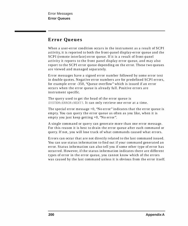
Error MessagesError Queues
Error Queues
When a user-error condition occurs in the instrument as a result of SCPI activity, it is reported to both the front-panel display-error queue and the SCPI (remote interface) error queue. If it is a result of front-panel activity it reports to the front panel display error queue, and may also report to the SCPI error queue depending on the error. These two queues are viewed and managed separately.
Error messages have a signed error number followed by some error text in double quotes. Negative error numbers are for predefined SCPI errors, for example error -350, “Queue overflow” which is issued if an error occurs when the error queue is already full. Positive errors are instrument specific.
The query used to get the head of the error queue is SYSTEM:ERROR:NEXT?. It can only retrieve one error at a time.
The special error message +0, “No error” indicates that the error queue is empty. You can query the error queue as often as you like, when it is empty you just keep getting +0, “No error”.
A single command or query can generate more than one error message. For this reason it is best to drain the error queue after each command or query. If not, you will lose track of what commands caused what errors.
Errors can occur that are not directly related to the last command issued. You can use status information to find out if your command generated an error. Status information can also tell you if some other type of error has occurred. However, if the status information indicates there are different types of error in the error queue, you cannot know which of the errors was caused by the last command unless it is obvious from the error itself.
200 Appendix A
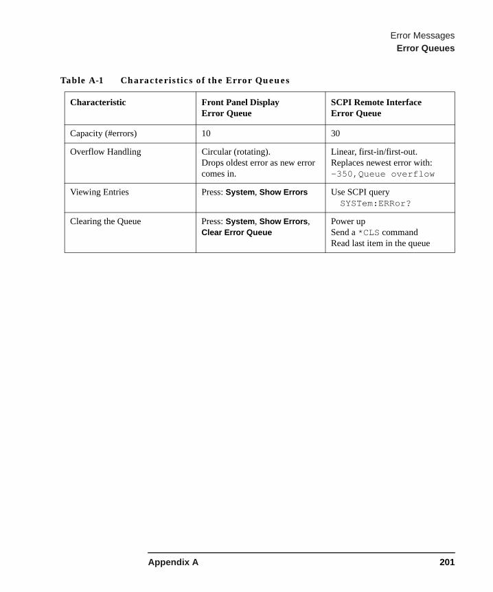
Error MessagesError Queues
Table A-1 Characteristics of the Error Queues
Characteristic Front Panel DisplayError Queue
SCPI Remote InterfaceError Queue
Capacity (#errors) 10 30
Overflow Handling Circular (rotating).Drops oldest error as new error comes in.
Linear, first-in/first-out.Replaces newest error with: -350,Queue overflow
Viewing Entries Press: System, Show Errors Use SCPI querySYSTem:ERRor?
Clearing the Queue Press: System, Show Errors,Clear Error Queue
Power upSend a *CLS commandRead last item in the queue
Appendix A 201
Error MessagesError Message Format
Error Message FormatThe system-defined error numbers are chosen on an enumerated (“1 of N”) basis. The error messages are listed in alphabetical order within each error message type section.
In this chapter, an explanation is included with each error to further clarify its meaning. The last error described in each class (for example, -400, -300, -200, -100) is a “generic” error.
Error messages appear at the bottom of the display.
202 Appendix A
Error MessagesError Message Types
Error Message TypesEvents do not generate more than one type of error. For example, an event that generates a query error will not generate a device-specific, execution, or command error.
Errors -499 to -400 These errors indicate that the instrument output queue control has detected a problem with the message exchange protocol described in IEEE 488.2, Chapter 6. Errors in this class set the query error bit (bit 2) in the event status register (IEEE 488.2, section 11.5.1). These errors correspond to message exchange protocol errors described in IEEE 488.2, 6.5. In this case:
• Either an attempt is being made to read data from the output queue when no output is either present or pending, or
• data in the output queue has been lost.
Errors -199 to -100 These errors indicate that the instrument parser detected an IEEE 488.2 syntax error. Errors in this class set the command error bit (bit 5) in the event status register (IEEE 488.2, section 11.5.1). In this case:
• Either an IEEE 488.2 syntax error has been detected by the parser (a control-to-device message was received that is in violation of the IEEE 488.2 standard. Possible violations include a data element which violates device listening formats or whose type is unacceptable to the device.), or
• an unrecognized header was received. These include incorrect device-specific headers and incorrect or unimplemented IEEE 488.2 common commands.
Errors 201 to 799 These errors indicate that a device operation did not properly complete, possibly due to an abnormal hardware or firmware condition. These codes are also used for self-test response errors. Errors in this class set the device-specific error bit (bit 3) in the event status register (IEEE 488.2, section 11.5.1).
The <error_message> string for a positive error is not defined by SCPI.
Appendix A 203

Error MessagesError Message Types
Errors -299 to -200 These errors indicate that an error has been detected by the instrument’s execution control block. The occurrence of any error in this class shall cause the execution error bit (bit 4) in the event status register (IEEE 488.2, section 11.5.1) to be set. One of the following events has occurred:
• A <PROGRAM DATA> element following a header was evaluated by the device as outside of its legal input range or is otherwise inconsistent with the device’s capabilities.
• A valid program message could not be properly executed due to some device condition.
Execution errors shall be reported by the device after rounding and expression evaluation operations have taken place. Rounding a numeric data element shall not be reported as an execution error. Events that generate execution errors shall not generate Command errors, device-specific errors, or Query errors.
204 Appendix A
Error MessagesNo Error
No Error
Error 0
0 No error
The queue is empty. Every error in the queue has been read or the queue was purposely cleared by power-on or *CLS.
Appendix A 205
Error MessagesQuery Errors
Query Errors
Errors -499 to -400
The instrument output queue control has detected a problem with the message exchange protocol described in IEEE 488.2, Chapter 6. Errors in this class set the query error bit (bit 2) in the event status register (IEEE 488.2, section 11.5.1). These errors correspond to message exchange protocol errors described in IEEE 488.2, 6.5.
In this case, either an attempt is being made to read data from the output queue when no output is either present or pending, or data in the output queue has been lost.
-440 Query UNTERMINATED after indefinite response
Indicates that a query was received in the same program message after a query requesting an indefinite response was executed (see IEEE 488.2, 6.3.7.5).
-430 Query DEADLOCKED
Indicates that a SCPI output queue has filled, preventing further SCPI command execution, and there is no more room left in the corresponding SCPI input queue to accept a query to read from the output queue. The system automatically discards output to correct the deadlock.
-420 Query UNTERMINATED
Indicates that a condition causing an UNTERMINATED query error occurred (see IEEE 488.2, 6.3.2.2). For example, the device was addressed to talk and an incomplete program message was received.
206 Appendix A
Error MessagesQuery Errors
-410 Query INTERRUPTED
Indicates that a condition causing an INTERRUPTED query error occurred (see IEEE 488.2, 6.3.2.7). For example, a query was followed by DAB or GET before a response was completely sent.
-400 Query Error
This is a generic query error for devices that cannot detect more specific errors. The code indicates only that a query error as defined in IEEE 488.2, 11.5.1.1.7 and 6.3 has occurred.
Appendix A 207

Error MessagesCommand Errors
Command Errors
Errors -199 to -100
The instrument parser detected an IEEE 488.2 syntax error. Errors in this class set the command error bit (bit 5) in the event status register (IEEE 488.2, section 11.5.1). In this case:
• Either an IEEE 488.2 syntax error has been detected by the parser(a control-to-device message was received that is in violation of the IEEE 488.2 standard. Possible violations include a data element which violates device listening formats or whose type is unacceptable to the device.), or
• an unrecognized header was received. These include incorrect device-specific headers and incorrect or unimplemented IEEE 488.2 common commands.
-178 Expression data not allowed
A legal expression data was encountered, but was not allowed by the device at this point in parsing.
-171 Invalid expression
The expression data element was invalid (see IEEE 488.2, 7.7.7.2). For example, unmatched parentheses or an illegal character.
-170 Expression error
This error, as well as error -178, is generated when parsing an expression data element. This particular error message is used if the device cannot detect a more specific error.
208 Appendix A
Error MessagesCommand Errors
-168 Block data not allowed
A legal block data element was encountered, but not allowed by the device at this point in the parsing.
-161 Invalid block data
A block data element was expected, but was invalid (see IEEE 488.2, 7.7.6.2). For example, an END message was received before the end length was satisfied.
-160 Block data error
This error, as well as error -168, is generated when parsing a block data element. This particular error message is used if the device cannot detect a more specific error.
-158 String data not allowed
A string data element was encountered, but not allowed by the device at this point in the parsing.
-151 Invalid string data
A string data element was expected, but was invalid (see IEEE 488.2, 7.7.5.2). For example, an END message was received before the terminal quote character.
-150 String data error
This error, as well as error -158, is generated when parsing a string data element. This particular error message is used if the device cannot detect a more specific error.
-148 Character data not allowed
A legal character data element was encountered where prohibited by the device.
Appendix A 209
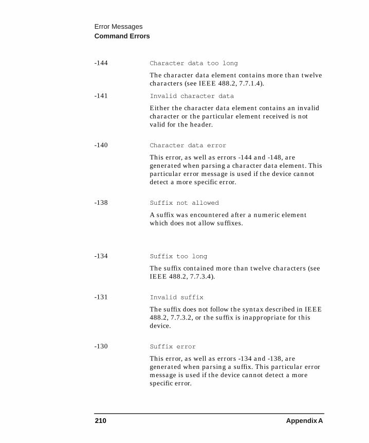
Error MessagesCommand Errors
-144 Character data too long
The character data element contains more than twelve characters (see IEEE 488.2, 7.7.1.4).
-141 Invalid character data
Either the character data element contains an invalid character or the particular element received is not valid for the header.
-140 Character data error
This error, as well as errors -144 and -148, are generated when parsing a character data element. This particular error message is used if the device cannot detect a more specific error.
-138 Suffix not allowed
A suffix was encountered after a numeric element which does not allow suffixes.
-134 Suffix too long
The suffix contained more than twelve characters (see IEEE 488.2, 7.7.3.4).
-131 Invalid suffix
The suffix does not follow the syntax described in IEEE 488.2, 7.7.3.2, or the suffix is inappropriate for this device.
-130 Suffix error
This error, as well as errors -134 and -138, are generated when parsing a suffix. This particular error message is used if the device cannot detect a more specific error.
210 Appendix A
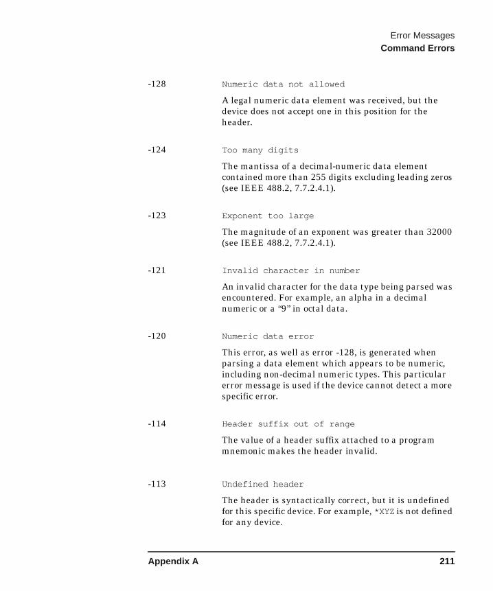
Error MessagesCommand Errors
-128 Numeric data not allowed
A legal numeric data element was received, but the device does not accept one in this position for the header.
-124 Too many digits
The mantissa of a decimal-numeric data element contained more than 255 digits excluding leading zeros (see IEEE 488.2, 7.7.2.4.1).
-123 Exponent too large
The magnitude of an exponent was greater than 32000 (see IEEE 488.2, 7.7.2.4.1).
-121 Invalid character in number
An invalid character for the data type being parsed was encountered. For example, an alpha in a decimal numeric or a “9” in octal data.
-120 Numeric data error
This error, as well as error -128, is generated when parsing a data element which appears to be numeric, including non-decimal numeric types. This particular error message is used if the device cannot detect a more specific error.
-114 Header suffix out of range
The value of a header suffix attached to a program mnemonic makes the header invalid.
-113 Undefined header
The header is syntactically correct, but it is undefined for this specific device. For example, *XYZ is not defined for any device.
Appendix A 211
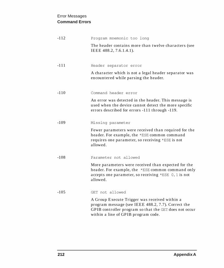
Error MessagesCommand Errors
-112 Program mnemonic too long
The header contains more than twelve characters (see IEEE 488.2, 7.6.1.4.1).
-111 Header separator error
A character which is not a legal header separator was encountered while parsing the header.
-110 Command header error
An error was detected in the header. This message is used when the device cannot detect the more specific errors described for errors -111 through -119.
-109 Missing parameter
Fewer parameters were received than required for the header. For example, the *ESE common command requires one parameter, so receiving *ESE is not allowed.
-108 Parameter not allowed
More parameters were received than expected for the header. For example, the *ESE common command only accepts one parameter, so receiving *ESE 0,1 is not allowed.
-105 GET not allowed
A Group Execute Trigger was received within a program message (see IEEE 488.2, 7.7). Correct the GPIB controller program so that the GET does not occur within a line of GPIB program code.
212 Appendix A
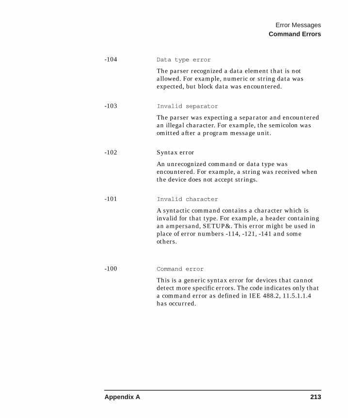
Error MessagesCommand Errors
-104 Data type error
The parser recognized a data element that is not allowed. For example, numeric or string data was expected, but block data was encountered.
-103 Invalid separator
The parser was expecting a separator and encountered an illegal character. For example, the semicolon was omitted after a program message unit.
-102 Syntax error
An unrecognized command or data type was encountered. For example, a string was received when the device does not accept strings.
-101 Invalid character
A syntactic command contains a character which is invalid for that type. For example, a header containing an ampersand, SETUP&. This error might be used in place of error numbers -114, -121, -141 and some others.
-100 Command error
This is a generic syntax error for devices that cannot detect more specific errors. The code indicates only that a command error as defined in IEE 488.2, 11.5.1.1.4 has occurred.
Appendix A 213
Error MessagesDevice-Specific Errors
Device-Specific Errors
Errors -399 to -300
Some device operations did not properly complete, possibly due to an abnormal hardware or firmware condition. These codes are also used for self-test response errors. Errors in this class set the device-specific error bit (bit 3) in the event status register (IEEE 488.2, section 11.5.1).
The <error_message> string for a positive error is not defined by SCPI.
-350 Queue Overflow
There is no room in the error queue and an error occurred but was not recorded.
-330 Self-Test Failed
A self-test error occurred due to one of the following reasons:
• IF filter offset x out of range
• IF gain out of range
• IF pad[x][y] value out of range
• Microwave range change x to y
• RF amp[x] floor too high
• RF cal x out of range amp[y]
• RF gain (x) out of range
• RF pad[x] value out of range
• Tuner EEPROM cal value out of range
214 Appendix A
Error MessagesDevice-Specific Errors
Errors 201 to 799
216 Invalid baud rate
Attempt to use invalid baud rate. Refer to User’s Guide for valid rates.
217 RS-232 Interface Error
An error occurred on the serial interface due to one of the following reasons:
• Input data overrun
An error occurred on the serial interface.
• Input data parity
An error occurred on the serial interface.
• Input data framing
An error occurred on the serial interface.
• Output data timeout
An error occurred on the serial interface
• Command input timeout
An error occurred on the serial interface.
219 Command not valid in this model
Indicates that the command sent from the remote interface does not apply to this model number.
300 IF autorange failed
The IF section could not be autoranged because of one of the following:
• RF att. is fixed
The IF section could not be autoranged because the RF front-end attenuation is fixed.
Appendix A 215
Error MessagesDevice-Specific Errors
• RF att. limit reached
The IF section could not be autoranged because the RF front-end attenuation limit is reached.
301 LO GPIB error
An LO GPIB error occurred because of one of the following:
• Did not become system controller
An attempt to become system controller failed, possibly because another controller is present on the LO GPIB bus.
• Need to be system controller
To perform the required action, the NFA needs to be the system controller on the LO GPIB bus and is not because a prior attempt to become the system controller failed.
• Controller collision
Another controller on the LO GPIB has attempted to use the bus concurrently with the NFA.
• Address bus timeout
Attempted to address bus and failed — check cabling connections.
• Write command timeout
Attempt to write command to device failed — check device address is correct.
• Read response timeout
Attempt to read response from device failed - check device address is not the same as the LO GPIB address.
216 Appendix A
Error MessagesDevice-Specific Errors
302 IF PLD error;Power detector read timed out
A read of the IF section power detector timed out.
303 User cal invalidated
The existing user cal has been invalidated because of one of the following reasons:
• Meas mode changed
The existing user cal has been invalidated because the measurement mode has been changed from that used for user cal.
• Freq outside cal range
The existing user cal has been invalidated because the current measurement frequencies lie partially or wholly outside the range of frequencies used for user cal.
• Fixed IF changed
The existing user cal has been invalidated because the fixed IF frequency has been changed from that used for user cal.
• Fixed LO changed
The existing user cal has been invalidated because the fixed LO frequency has been changed from that used for user cal.
• Sideband changed
The existing user cal has been invalidated because the sideband has been changed from that used for user cal.
Appendix A 217

Error MessagesDevice-Specific Errors
304 Alignment failed
The alignment failed because of one of the following reasons:
• Noise greater than signal
The reading at the IF detector was greater when only the noise floor of the instrument was present compared to when the alignment CW signal was present.
• Gain less than 0
During alignment, the measured value of the IF section gain was less than 0.
305 Mode setup error
A mode setup error occurred because of one of the following:
• System input frequency out of range
One or more system input frequencies are out of range. If using a frequency list, check that all entries are valid for current measurement mode.
• External LO frequency out of range
One or more external LO frequencies are out of range. Check that the LO frequency limits are set correctly and check the entered measurement frequencies and measurement mode.
• Stop freq must be less than fixed LO freq
The current measurement mode requires that the stop frequency must be less than the fixed LO frequency.
• Start freq must be greater than start IF freq
The current measurement mode requires that the start RF (input to DUT) frequency must be greater than the start IF (output from DUT) frequency.
218 Appendix A
Error MessagesDevice-Specific Errors
• LO - Stop freq must be >= min system input freq
The current measurement mode requires that the stop RF (input to DUT) frequency must be more than the minimum system input frequency away from the fixed LO frequency.
• Start freq must be greater than fixed LO freq
The current measurement mode requires that the start frequency must be greater than the fixed LO frequency.
• Stop IF freq must be less than fixed LO freq
The current measurement mode requires that the stop IF (output to DUT) frequency must less than the fixed LO frequency.
• Start - LO freq must be >= min system input freq
The current measurement mode requires that the start RF (input to DUT) frequency must be more than the minimum system input frequency away from the fixed LO frequency.
• Stop freq must be less than stop RF freq
The current measurement mode requires that the stop IF (output to DUT) frequency must be less than the stop RF (input to DUT) frequency.
• Start freq must be greater than start RF freq
The current measurement mode requires that the start IF (output to DUT) frequency must be greater than the start RF (input to DUT) frequency.
Appendix A 219

Error MessagesDevice-Specific Errors
• Stop RF freq must be less than fixed LO freq
The current measurement mode requires that the stop RF (input to DUT) frequency must be less than the fixed LO frequency.
• Start freq must be greater than fixed IF freq
The current measurement mode requires that the start RF (input to DUT) frequency must be greater than the fixed IF frequency.
• Start LO freq must be greater than fixed IF freq
The current measurement mode requires that the start LO frequency must be greater than the fixed IF frequency.
• Stop freq must be less than fixed IF freq
The current measurement mode requires that the stop RF (input to DUT) frequency must be less than the fixed IF frequency.
• Stop freq must be less than stop LO freq
The current measurement mode requires that the stop RF (input to DUT) frequency must be less than the stop LO frequency.
306 Invalid input attenuation
An attempt was made to set an invalid RF front-end attenuation limit for calibration.
307 Input attenuation x dB not calibrated
Corrected measurements have been requested and the required RF front-end attenuation setting of x dB has not been calibrated.
220 Appendix A

Error MessagesDevice-Specific Errors
308 Invalid frequency list for measurement mode
A frequency within the frequency list cannot be used to make a measurement in the current mode.
309 No entries in frequency list
A measurement was attempted with List frequency mode or a SCPI query of the frequency list table was made and the frequency list table is empty.
310 No entries in ENR table
A measurement was attempted or a SCPI query of an ENR table was made and there were no entries in the relevant ENR table (Common, Meas or Cal).
311 No entries in limit line table
An attempt is made to either display or test against a limit line table, which has no entries.
312 RF re-range required: Meas. restarted
During a continuous measurement, a change of RF front-end attenuation was required. To do this the measurement needs to be restarted.
313 IF over range req. RF re-range: Meas. restarted
During a continuous measurement, a IF section over range condition occurred, requiring a change of RF front-end attenuation. To do this the measurement needs to be restarted.
Appendix A 221
Error MessagesDevice-Specific Errors
314 No entries in loss table
A measurement is attempted or a SCPI query of a before of after loss table is made and there are no entries in the relevant loss table.
315 Microwave input attenuation x dB not calibrated
Corrected measurements have been requested and the required microwave front-end attenuation setting of x dB has not been calibrated.
316 Thot must be greater than Tcold
A spot Thot has been specified which is not greater than Tcold.
500 Hardware config error
A hardware configuration error occurred due to one of the following reasons:
• Unknown product number
During start-up, an attempt to match the hardware found against the NFA's product number could not be made because the product number was unknown. This is a fatal hardware configuration error.
• HW ID x in slot y not required
A card with ID x was found in slot y but for this product number is not required. This is a non-fatal hardware configuration error.
• HW ID x is missing
A card with ID x was expected for this product number but was not found. This is a fatal hardware configuration error.
222 Appendix A
Error MessagesDevice-Specific Errors
• HW ID x must be in slot y, not z
A card with ID x was found in slot z but was expected to be found in slot y for this product number. This is a fatal hardware configuration error.
• Measurement not possible
An attempt was made to perform a measurement but a previous fatal hardware configuration error has occurred, preventing measurements.
• Option ’X’ not installed
Software option ’X’ must be enabled for this product number, but was not installed. This is a fatal hardware configuration error.
501 SNS read failure
An attempt to read from the SNS failed. This could be due to SNS cable problems such as poor connection or disconnection while reading.
502 SNS write failure
An attempt to write to the SNS failed. This could be due to SNS cable problems such as poor connection or disconnection while reading.
603 Illegal MSDOS name given
An invalid file name has been specified. Use filenames with a maximum of 8 characters (letters and digits only) and use a 3 character extension. Note that lowercase and uppercase are perceived as the same.
604 File already exists
Attempt to store to a file that already exists. Delete or rename the old file and try again.
Appendix A 223

Error MessagesDevice-Specific Errors
605 Media is protected
A store was attempted to a write-protected device.
606 Media is not writable
A store was attempted to a read-only device.
607 File name error
An invalid file name has been specified. Use filenames with a maximum of 8 characters (letters and digits only) and use a 3 character extension. Note that lowercase and uppercase are perceived as the same.
610 File access is denied
The file is protected or hidden and cannot be accessed.
612 File does not exist
The file you were trying to recall could not be found.
614 Bad or missing disk
The floppy is not inserted or the directory could not be read. Insert a known good disk and try again.
615 Corrupted file
The file that you were trying to load is corrupt.
224 Appendix A

Error MessagesDevice-Specific Errors
660 YTF align error
A YIG tuned filter alignment error has occurred because of one of the following reasons:
• Peak power too low
During a YIG tuned filter alignment a peak was found but its level was below the expected threshold. If this error occurs then the quality of the YIG tuned filter alignment is questionable.
• Peak/floor too small
During a YIG tuned filter alignment the level of a peak above the noise floor was too small. If this error occurs then the quality of the YIG tuned filter alignment is questionable.
• Image/floor too small
During a YIG tuned filter alignment the level of an image response above the noise floor was too small. If this error occurs then the quality of the YIG tuned filter alignment is questionable.
700 No printer response
An attempt to identify the printer failed.
701 Invalid printer response
In attempting to identify the printer an invalid response was received. Check that you are using a supported printer. Be sure you are using the proper cable and that it is securely fastened.
Appendix A 225
Error MessagesDevice-Specific Errors
702 Unsupported printer
A printer which is recognized, but known to be unsupported was identified. This printer cannot be used with the NFA. For example, a printer only supported by Microsoft Windows will generate this error.
704 Printer interface error
An error occurred while trying to print. Make sure the printer is turned on and properly connected.
703 Unknown printer
In attempting to identify the printer, a valid response was received but the printer is not known to the analyzer. Use the Define Custom printer menu under Print Setup to configure the printer.
705 Printer type is none
The current printer type is set to None, so no print operations are possible. Change the type in the Print Setup menu and try again.
751 Instrument state may be corrupt, state reset to initial values
An attempt was made to load a possibly corrupt state. The instrument state will be reset to the state prior to the attempt to load. If the state load was for a user preset, then the instrument state will be reset to the factory state.
752 Unable to load state from file
An attempt to load a state from the File Manager or through MMEM:LOAD:STAT failed. Preceding error messages may indicate the cause of failure.
226 Appendix A
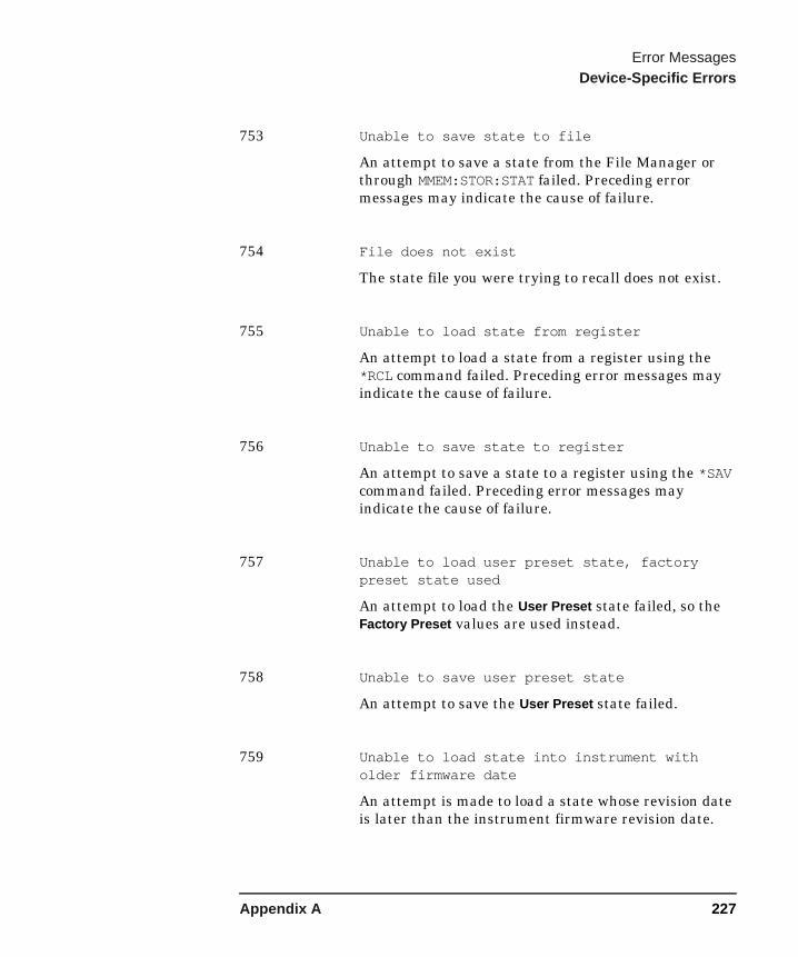
Error MessagesDevice-Specific Errors
753 Unable to save state to file
An attempt to save a state from the File Manager or through MMEM:STOR:STAT failed. Preceding error messages may indicate the cause of failure.
754 File does not exist
The state file you were trying to recall does not exist.
755 Unable to load state from register
An attempt to load a state from a register using the *RCL command failed. Preceding error messages may indicate the cause of failure.
756 Unable to save state to register
An attempt to save a state to a register using the *SAV command failed. Preceding error messages may indicate the cause of failure.
757 Unable to load user preset state, factory preset state used
An attempt to load the User Preset state failed, so the Factory Preset values are used instead.
758 Unable to save user preset state
An attempt to save the User Preset state failed.
759 Unable to load state into instrument with older firmware date
An attempt is made to load a state whose revision date is later than the instrument firmware revision date.
Appendix A 227
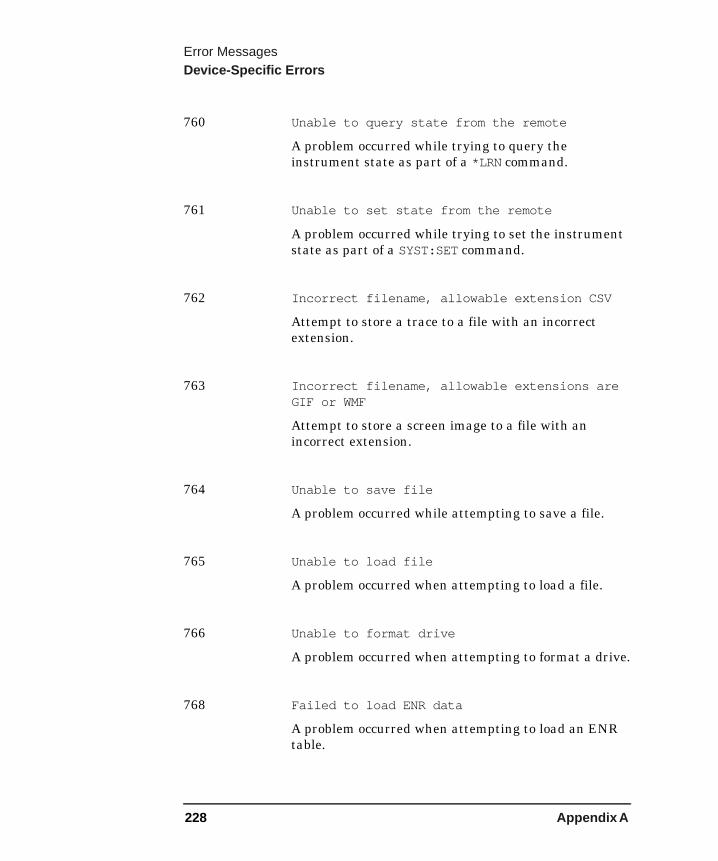
Error MessagesDevice-Specific Errors
760 Unable to query state from the remote
A problem occurred while trying to query the instrument state as part of a *LRN command.
761 Unable to set state from the remote
A problem occurred while trying to set the instrument state as part of a SYST:SET command.
762 Incorrect filename, allowable extension CSV
Attempt to store a trace to a file with an incorrect extension.
763 Incorrect filename, allowable extensions are GIF or WMF
Attempt to store a screen image to a file with an incorrect extension.
764 Unable to save file
A problem occurred while attempting to save a file.
765 Unable to load file
A problem occurred when attempting to load a file.
766 Unable to format drive
A problem occurred when attempting to format a drive.
768 Failed to load ENR data
A problem occurred when attempting to load an ENR table.
228 Appendix A

Error MessagesDevice-Specific Errors
769 Failed to store ENR data
A problem occurred when attempting to store an ENR table.
770 Incorrect filename, allowable extension ENR
Attempt to store an ENR table to a file with an incorrect extension.
771 Failed to load Freq list
A problem occurred when attempting to load a frequency list.
772 Failed to store Freq list
A problem occurred when attempting to store a frequency list.
773 Incorrect filename, allowable extension LST
Attempt to store frequency list data to a file with an incorrect extension.
774 Failed to load Limit line
A problem occurred when attempting to load a limit line.
775 Failed to store Limit line
A problem occurred when attempting to store a limit line.
776 Incorrect filename, allowable extensions LIM
Attempt to store limit line data to a file with an incorrect extension.
Appendix A 229
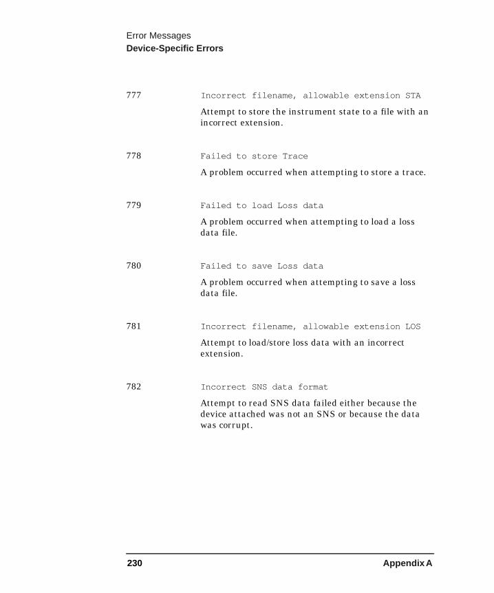
Error MessagesDevice-Specific Errors
777 Incorrect filename, allowable extension STA
Attempt to store the instrument state to a file with an incorrect extension.
778 Failed to store Trace
A problem occurred when attempting to store a trace.
779 Failed to load Loss data
A problem occurred when attempting to load a loss data file.
780 Failed to save Loss data
A problem occurred when attempting to save a loss data file.
781 Incorrect filename, allowable extension LOS
Attempt to load/store loss data with an incorrect extension.
782 Incorrect SNS data format
Attempt to read SNS data failed either because the device attached was not an SNS or because the data was corrupt.
230 Appendix A
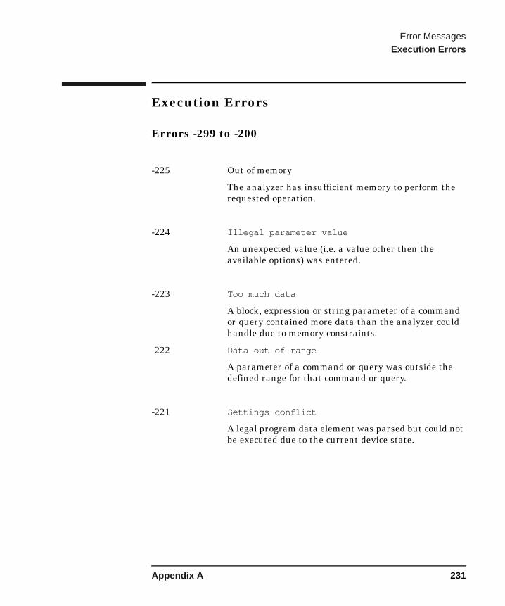
Error MessagesExecution Errors
Execution Errors
Errors -299 to -200
-225 Out of memory
The analyzer has insufficient memory to perform the requested operation.
-224 Illegal parameter value
An unexpected value (i.e. a value other then the available options) was entered.
-223 Too much data
A block, expression or string parameter of a command or query contained more data than the analyzer could handle due to memory constraints.
-222 Data out of range
A parameter of a command or query was outside the defined range for that command or query.
-221 Settings conflict
A legal program data element was parsed but could not be executed due to the current device state.
Appendix A 231

Error MessagesExecution Errors
232 Appendix A

B NFA Status Registers
This appendix describes what status registers are and how to use them. Also provided is a comprehensive description of all bits of the registers in NFA Noise Figure Analyzers.
233

NFA Status RegistersUsing the Analyzer Status Registers
Using the Analyzer Status RegistersThe status system is comprised of multiple registers which are arranged in a hierarchical order. The lower-priority status registers propagate their data to the higher-priority registers in the data structures by means of summary bits. The status byte register is at the top of the hierarchy and contains the general status information for the Noise Figure Analyzer events and conditions. All other individual registers are used to determine the specific events or conditions.
You can determine the state of certain Noise Figure Analyzer hardware and firmware events and conditions by programming the status register system. The diagram on page 239 shows all the Noise Figure Analyzer status registers and their hierarchy.
Why Would You Use the Status Registers?
Your program often needs to be able to detect and manage error conditions or changes in Noise Figure Analyzer status. There are two methods you can use to programmatically access the information in status registers:
• The polling method
• The service request (SRQ) method
In the polling method, the Noise Figure Analyzer has a passive role. It only tells the controller that conditions have changed when the controller asks the right question. In the SRQ method, the Noise Figure Analyzer takes a more active role. It tells the controller when there has been a condition change without the controller asking. Either method allows you to monitor one or more conditions.
The polling method works well if you do not need to know about changes the moment they occur. The SRQ method should be used if you must know immediately when a condition changes. To detect a change using the polling method, the program must repeatedly read the registers.
Use the SRQ method when:
— you need time-critical notification of changes— you are monitoring more than one device which supports SRQs— you need to have the controller do something else while waiting
234 Appendix B

NFA Status RegistersUsing the Analyzer Status Registers
— you can’t afford the performance penalty inherent to polling
Use polling when:
— your programming language/development environment does not support SRQ interrupts
— you want to write a simple, single-purpose program and don’t want the added complexity of setting up an SRQ handler
To monitor a condition:
1. Determine which register contains the bit that reports the condition.2. Send the unique SCPI query that reads that register.3. Examine the bit to see if the condition has changed.
Using the Status Registers
Most monitoring of the Noise Figure Analyzer conditions is done at the highest level using the IEEE common commands indicated below. Complete command descriptions are available in Chapter 2 , “IEEE 488.2 Common Commands,” on page 11:
*CLS (clear status) clears the status byte by emptying the error queue and clearing all the event registers.
*ESE, *ESE? (event status enable) sets and queries the bits in the enable register part of the standard event status register.
*ESR? (event status register) queries and clears the event register part of the standard event status register.
*OPC, *OPC? (operation complete) sets the standard event status register to monitor the completion of all commands. The query stops any new commands from being processed until the current processing is complete, then returns a ‘1’.
*SRE, *SRE? (service request enable) sets and queries the value of the service request enable register.
*STB? (status byte) queries the value of the status byte register without erasing its contents.
Individual status registers can be set and queried using the commands in the STATus subsystem of the language reference. A “status register” is actually composed of five physical registers: a condition register, two transition registers, an event enable register and an event register. You can use the :STATus commands to:
Appendix B 235

NFA Status RegistersUsing the Analyzer Status Registers
• Check the Noise Figure Analyzer hardware and firmware status.
Do this by querying the condition registers which continuously monitor status. These registers represent the current state of the Noise Figure Analyzer. Bits in a condition register are updated in real time. When the condition monitored by a particular bit becomes true, the bit is set to 1. When the condition becomes false, the bit is reset to 0.
• Monitor a particular bit (condition), or bits.
Once you have enabled a bit, using the event enable register, the Noise Figure Analyzer will monitor that particular bit. If the bit becomes true in the event register, it will stay set until the event register is cleared. Querying the event register allows you to detect that this condition occurred even if the condition no longer exists. The event register can only be cleared by querying it or sending the *CLS command, which clears all event registers.
• Monitor a change in the condition of a particular bit, or bits.
Once you have enabled a bit, the Noise Figure Analyzer will monitor it for a change in its condition. The transition registers are preset to register the conditions going from 0 to 1, positive transitions. This can be changed so that the selected bit is detected if it goes from true to false (negative transition), or if either transition occurs. Querying the event register allows you to detect that a change in this condition occurred. The event register can only be cleared by querying it or sending the *CLS command, which clears all event registers.
Setting and Querying the Registers
Each bit in a register is represented by a numerical value based on its location. See Figure B-1 below. This number is sent with the command, to enable a particular bit. If you want to enable more than one bit, you would send the sum of all the bits that you are interested in.
For example, to enable bit 0 and bit 6 of standard event status register, you would send the command *ESE 65 (1 + 64 = 65).
The results of a query are evaluated in a similar way. If the *STB? command returns a decimal value of 140, (140 = 128 + 8 + 4) then the bit 7 is true, bit 3 is true and bit 2 is true.
236 Appendix B
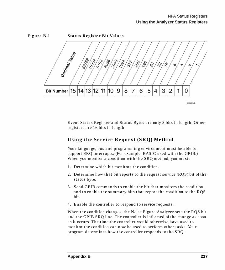
NFA Status RegistersUsing the Analyzer Status Registers
Figure B-1 Status Register Bit Values
Event Status Register and Status Bytes are only 8 bits in length. Other registers are 16 bits in length.
Using the Service Request (SRQ) Method
Your language, bus and programming environment must be able to support SRQ interrupts. (For example, BASIC used with the GPIB.) When you monitor a condition with the SRQ method, you must:
1. Determine which bit monitors the condition.
2. Determine how that bit reports to the request service (RQS) bit of the status byte.
3. Send GPIB commands to enable the bit that monitors the condition and to enable the summary bits that report the condition to the RQS bit.
4. Enable the controller to respond to service requests.
When the condition changes, the Noise Figure Analyzer sets the RQS bit and the GPIB SRQ line. The controller is informed of the change as soon as it occurs. The time the controller would otherwise have used to monitor the condition can now be used to perform other tasks. Your program determines how the controller responds to the SRQ.
Bit Number 789101112131415 6 5 4 3 2 1 0
2048
512
32
16 48 1
16384
8192
4096
1024
128
256
64
Decim
alValu
e
32768
2
ck730a
Appendix B 237

NFA Status RegistersUsing the Analyzer Status Registers
Generating a Service Request
To use the SRQ method, you must understand how service requests are generated. Bit 6 of the status byte register is the request service (RQS) bit. The RQS bit is set whenever something (that it has been configured to report using *SRE) changes. It is cleared when the status byte register is queried using *SRE? (with a serial poll.) It can be queried without erasing the contents with *STB?.
When a register set causes a summary bit in the status byte to change from 0 to 1, the analyzer can initiate the service request (SRQ) process. However, the process is only initiated if both of the following are true:
• The corresponding bit of the service request enable register is set to 1.
• The analyzer has no service request pending. (A service request is considered to be pending between the time the analyzer SRQ process is initiated and the time the controller reads the status byte register.)
The SRQ process sets the GPIB SRQ line true. It also sets the status byte request service (RQS) bit to 1. Both actions are necessary to inform the controller that the Noise Figure Analyzer requires service. Setting the SRQ line, only informs the controller that some device on the bus requires service. Setting the RQS bit allows the controller to determine which device requires service.
If your program enables the controller to detect and respond to service requests, it should instruct the controller to perform a serial poll when the GPIB SRQ line is set true. Each device on the bus returns the contents of its status byte register in response to this poll. The device whose RQS bit is set to 1 is the device that requested service.
NOTE When you read the status byte register with a serial poll, the RQS bit is reset to 0. Other bits in the register are not affected.
Restarting a measurement (:INITiate command) can cause the measuring bit to pulse low, which causes an SRQ if the status register is configured to SRQ on end-of-measurement. To avoid this:
• Set :INITiate:CONTinuous off.
• Set/enable the status registers.
• Restart the measurement (send :INITiate).
238 Appendix B

NFA Status RegistersOverall Status Byte Register System
Overall Status Byte Register System
Appendix B 239
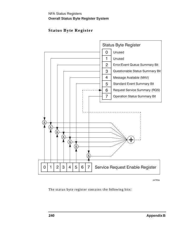
NFA Status RegistersOverall Status Byte Register System
Status Byte Register
The status byte register contains the following bits:
ck763a
+
&
&
&
&
&
&
&
Unused
Status Byte Register
Unused
Error/Event Queue Summary Bit
Questionable Summary BitStatus
Message Available (MAV)
Standard Event Summary Bit
Request Service Summary (RQS)
Operation Summary BitStatus
0
0
1
1
2
2
3
3
4
4
5
5
6
6
7 Service Request Enable Register
7
240 Appendix B
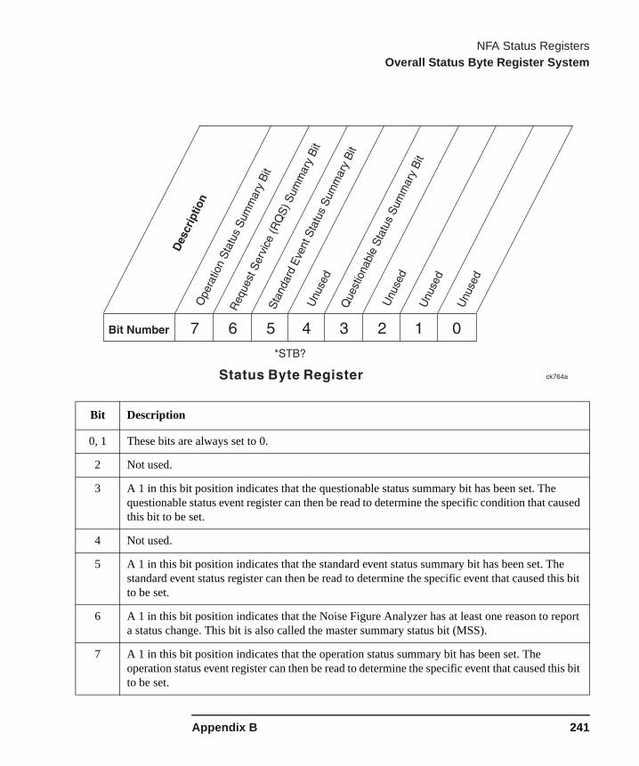
NFA Status RegistersOverall Status Byte Register System
Bit Description
0, 1 These bits are always set to 0.
2 Not used.
3 A 1 in this bit position indicates that the questionable status summary bit has been set. The questionable status event register can then be read to determine the specific condition that caused this bit to be set.
4 Not used.
5 A 1 in this bit position indicates that the standard event status summary bit has been set. The standard event status register can then be read to determine the specific event that caused this bit to be set.
6 A 1 in this bit position indicates that the Noise Figure Analyzer has at least one reason to report a status change. This bit is also called the master summary status bit (MSS).
7 A 1 in this bit position indicates that the operation status summary bit has been set. The operation status event register can then be read to determine the specific event that caused this bit to be set.
Appendix B 241

NFA Status RegistersOverall Status Byte Register System
To query the status byte register, send the command *STB? The response will be the decimal sum of the bits which are set to 1. For example, if bit number 7 and bit number 3 are set to 1, the decimal sum of the 2 bits is 128 plus 8. So the decimal value 136 is returned.
The status byte service request enable register lets you choose which bits in the Status Byte Register will trigger a service request. Send the command *SRE <number> where <number> is the sum of the decimal values of the bits you want to enable plus the decimal value of bit 6. For example, assume that you want to enable bit 7 so that whenever the operation status summary bit is set to 1 it will trigger a service request. Send the command *SRE 192 (128 + 64). You must always add 64 (the numeric value of RQS bit 6) to your numeric sum when you enable any bits for a service request. The command *SRE? returns the decimal value of the sum of the bits previously enabled with the *SRE <number> command.
Bit Number
Dec
imal
Val
ue
128
64 32 16 8 4 2 1
7 6 5 4 3 2 1 0
ck726aService Request Enable Register
*SRE <num>
*SRE?
242 Appendix B

NFA Status RegistersOverall Status Byte Register System
Summary Status Bits
Status registers (except for the Status Byte Register) consist of registers whose contents are programmed in order to produce status summary bits. These summary bits are then manipulated as follows:
The condition register passes summary bits to the negative and positive transition filters, after which they are stored in the event register. The contents of the event register are logically ANDed with the contents of the event enable register and the result is logically ORed to produce a status summary bit. The status summary bit is then passed to the Status Byte Register directly, or through the Questionable Status register and then to the Status Byte Register.
Condition Register A condition register continuously monitors the
hardware and firmware status of the Noise Figure Analyzer. There is no latching or buffering for a condition register. It is updated in real time.
Negative Transition Register A negative transition register specifies the bits in the
condition register that will set corresponding bits in the event register when the condition bit changes from 1 to 0.
Positive Transition Register A positive transition register specifies the bits in the
condition register that will set corresponding bits in the event register when the condition bit changes from 0 to 1.
Event Register An event register latches transition events from the
condition register as specified by the positive and negative transition filters. Bits in the event register are latched, and once set, they remain set until cleared by either querying the register contents or sending the *CLS command.
Event Enable Register An enable register specifies the bits in the event
Appendix B 243
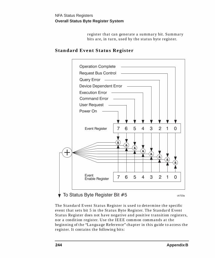
NFA Status RegistersOverall Status Byte Register System
register that can generate a summary bit. Summary bits are, in turn, used by the status byte register.
Standard Event Status Register
The Standard Event Status Register is used to determine the specific event that sets bit 5 in the Status Byte Register. The Standard Event Status Register does not have negative and positive transition registers, nor a condition register. Use the IEEE common commands at the beginning of the “Language Reference” chapter in this guide to access the register. It contains the following bits:
+
To Status Byte Register Bit #5
&&
&&
&&
&
&
Request Bus Control
Operation Complete
Query Error
Device Dependent Error
Execution Error
Command Error
User Request
Event Register
EventEnable Register
Power On
ck723a
01234567
01234567
244 Appendix B

NFA Status RegistersOverall Status Byte Register System
ent
CPI
on.
To query the Standard Event Status Register, send the command *ESR?.
Bit Description
0 A 1 in this bit position indicates that all pending operations were completed following execution of the *OPC command.
1 This bit is always set to 0. (The Noise Figure Analyzer does not request control.)
2 A 1 in this bit position indicates that a query error has occurred. Query errors have SCPI error numbers from −499 to –400.
3 A 1 in this bit position indicates that a device dependent error has occurred. Device dependerrors have SCPI error numbers from –399 to –300 and 1 to 32767.
4 A 1 in this bit position indicates that an execution error has occurred. Execution errors haveSCPI error numbers from –299 to –200.
5 A 1 in this bit position indicates that a command error has occurred. Command errors have Serror numbers from –199 to –100.
6 Not used.
7 A 1 in this bit position indicates that the Noise Figure Analyzer has been turned off and then
Appendix B 245

NFA Status RegistersOverall Status Byte Register System
The response will be the decimal sum of the bits which are set to 1. For example, if bit number 7 and bit number 3 are set to 1, the decimal sum of the 2 bits is 128 plus 8. So the decimal value 136 is returned.
The event enable register in the Standard Event Status Register lets you choose which bits will set the summary bit (bit 5 of the Status Byte Register) to 1. Send the command *ESE <number> where <number> is the sum of the decimal values of the bits you want to enable. For example, to enable bit 7 and bit 6 so that whenever either of those bits is set to 1, the standard event status summary bit of the Status Byte Register will be set to 1, send the command *ESE 192 (128 + 64). The command *ESE? returns the decimal value of the sum of the bits previously enabled with the *ESE <number> command.
Bit Number
Dec
imal
Val
ue
128
64 32 16 8 4 2 1
7 6 5 4 3 2 1 0
ck728aStandard Event Status Enable Register
*ESE <num>
*ESE?
246 Appendix B

NFA Status RegistersOverall Status Byte Register System
Operation Status Register
Figure B-2 Status Operation Register
Appendix B 247

NFA Status RegistersOverall Status Byte Register System
The Operation Status Register is used to determine the specific event that sets bit 7 in the Status Byte Register. The Operation Status Register consists of the following registers:
Operation Status condition registerOperation Status positive transition filterOperation Status negative transition filterOperation Status event registerOperation Status event enable register
The Operation Status Condition Register contains the following bits:
Figure B-3 Status Operation Condition
Bit Description
0-2 Unused. These bits are always set to 0.
3 A 1 in this bit position indicates that a sweep is in progress.
4 A 1 in this bit position indicates that a measurement is in progress.
5,6 Not used.
7 Indicates that a user calibration is in progress.
248 Appendix B

NFA Status RegistersOverall Status Byte Register System
r,
The Operation Status Register continuously monitors the operational status of the Noise Figure Analyzer, and is read-only. To query the register, send the command :STATus:OPERation:CONDition? The response will be the decimal sum of the bits which are set to 1. For example, if bit number 9 and bit number 3 are set to 1, the decimal sum of the 2 bits is 512 plus 8. So the decimal value 520 is returned.
The transition filter specifies which types of bit state changes in the condition register will set corresponding bits in the event register. The changes may be positive (from 0 to 1) or negative (from 1 to 0). Send the command :STATus:OPERation:NTRansition <num> (negative transition) or :STATus:OPERation:PTRansition <num> (positive transition) where <num> is the sum of the decimal values of the bits you want to enable.
The Operation Status Event Register latches transition events from the condition register as specified by the transition filters. Event registers are destructive read-only. Reading data from an event register will clear the content of that register. To query the event register, send the command :STATus:OPERation[:EVENt]?
8–14 Reserved. These bits are not used by the Noise Figure Analyzebut are for future use with other Agilent products.
15 Always Zero (0).
Bit Description
Appendix B 249

NFA Status RegistersOverall Status Byte Register System
Figure B-4 Status Opration Enable
The Operation Status event enable register lets you choose which bits will set the Operation Status Summary bit (bit 7) of the Status Byte Register to 1. Send the command :STATus:OPERation:ENABle <num> where <num> is the sum of the decimal values of the bits you want to enable. For example, to enable bit 9 and bit 3 so that whenever either of those bits is set to 1, the operation status summary bit of the Status Byte Register will be set to 1, send the command :STATus:OPERation:ENABle 520 (512 + 8). The command :STATus:OPERation:ENABle? returns the decimal value of the sum of the bits previously enabled with the :STATus:OPERation:ENABle <num> command.
Bit Number 789101112131415 6 5 4 3 2 1 02048
512
32
16 48 1
16384
8192
4096
1024
128
256
64
Decim
alValu
e
32768
2
ck767aOperation Event Enable RegisterStatus
STATus:OPERation:ENABle <num>
STATus:OPERation:ENABle?
250 Appendix B
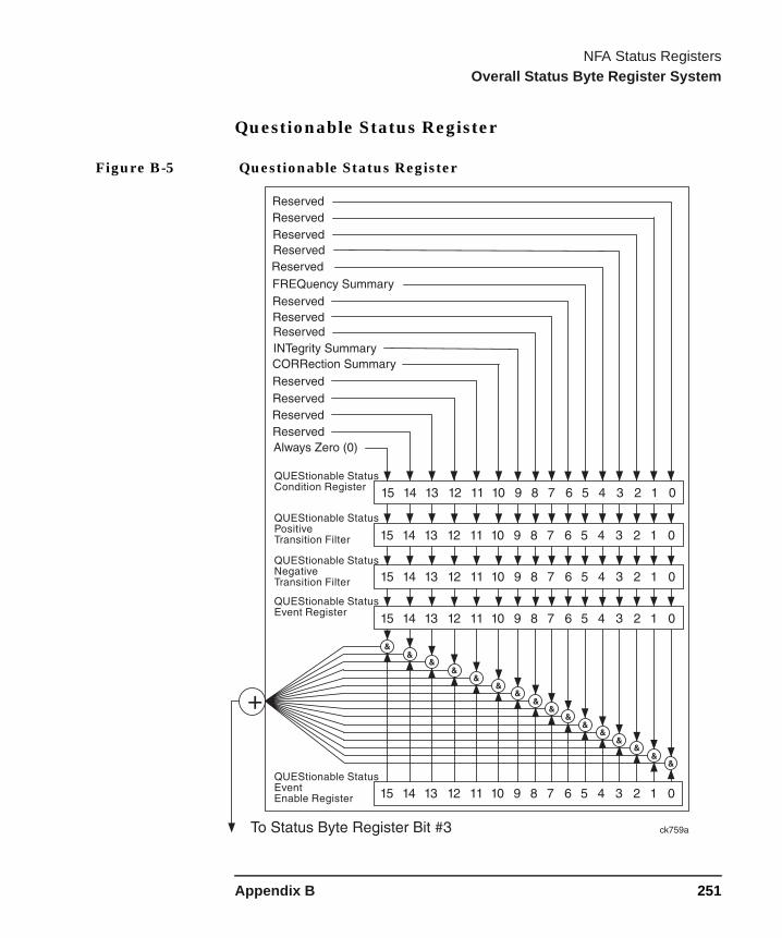
NFA Status RegistersOverall Status Byte Register System
Questionable Status Register
Figure B-5 Questionable Status Register
Appendix B 251
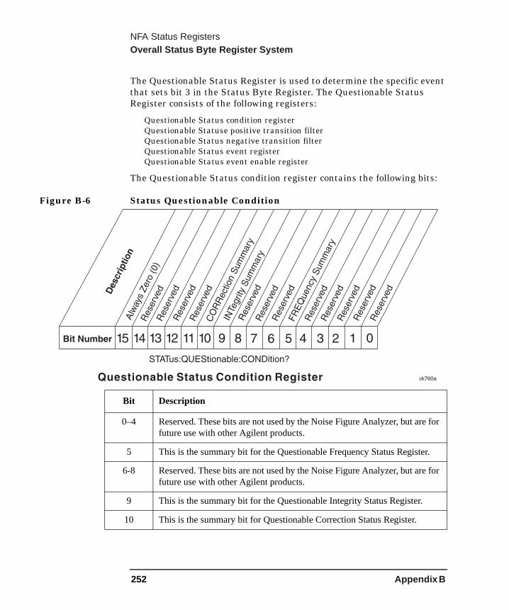
NFA Status RegistersOverall Status Byte Register System
for
.
for
The Questionable Status Register is used to determine the specific event that sets bit 3 in the Status Byte Register. The Questionable Status Register consists of the following registers:
Questionable Status condition registerQuestionable Statuse positive transition filterQuestionable Status negative transition filterQuestionable Status event registerQuestionable Status event enable register
The Questionable Status condition register contains the following bits:
Figure B-6 Status Questionable Condition
Bit Description
0–4 Reserved. These bits are not used by the Noise Figure Analyzer, but arefuture use with other Agilent products.
5 This is the summary bit for the Questionable Frequency Status Register
6-8 Reserved. These bits are not used by the Noise Figure Analyzer, but arefuture use with other Agilent products.
9 This is the summary bit for the Questionable Integrity Status Register.
10 This is the summary bit for Questionable Correction Status Register.
252 Appendix B
NFA Status RegistersOverall Status Byte Register System
for
The Questionable Status condition register continuously monitors the hardware and firmware status of the Noise Figure Analyzer. Condition registers are read-only. To query the condition register, send the command :STATus:QUEStionable:CONDition? The response will be the decimal sum of the bits which are set to 1. For example, if bit number 9 and bit number 3 are set to 1, the decimal sum of the 2 bits is 512 plus 8. So the decimal value 520 is returned.
The transition filter specifies which types of bit state changes in the condition register will set corresponding bits in the event register. The changes may be positive (from 0 to 1) or negative (from 1 to 0). Send the command :STATus:QUEStionable:NTRansition <num> (negative transition) or :STATus:QUEStionable:PTRansition <num> (positive transition) where <num> is the sum of the decimal values of the bits you want to enable.
The Questionable Status event register latches transition events from the condition register as specified by the transition filters. Event registers are destructive read-only. Reading data from an event register will clear the content of that register. To query the event register, send the command :STATus:QUEStionable[:EVENt]?
11–14 Reserved. These bits are not used by the Noise Figure Analyzer, but arefuture use with other Agilent products.
15 Always Zero (0).
Bit Description
Appendix B 253
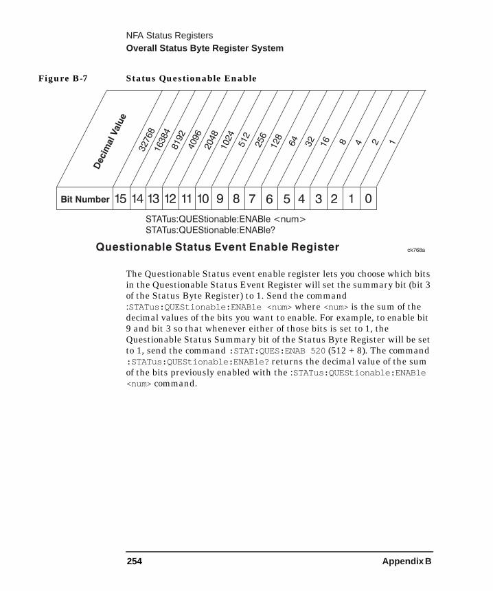
NFA Status RegistersOverall Status Byte Register System
Figure B-7 Status Questionable Enable
The Questionable Status event enable register lets you choose which bits in the Questionable Status Event Register will set the summary bit (bit 3 of the Status Byte Register) to 1. Send the command :STATus:QUEStionable:ENABle <num> where <num> is the sum of the decimal values of the bits you want to enable. For example, to enable bit 9 and bit 3 so that whenever either of those bits is set to 1, the Questionable Status Summary bit of the Status Byte Register will be set to 1, send the command :STAT:QUES:ENAB 520 (512 + 8). The command :STATus:QUEStionable:ENABle? returns the decimal value of the sum of the bits previously enabled with the :STATus:QUEStionable:ENABle <num> command.
Bit Number 789101112131415 6 5 4 3 2 1 02048
512
32
16 48 1
16384
8192
4096
1024
128
256
64
Decim
alValu
e
32768
2
ck768aQuestionable Event Enable RegisterStatus
STATus:QUEStionable:ENABle <num>
STATus:QUEStionable:ENABle?
254 Appendix B
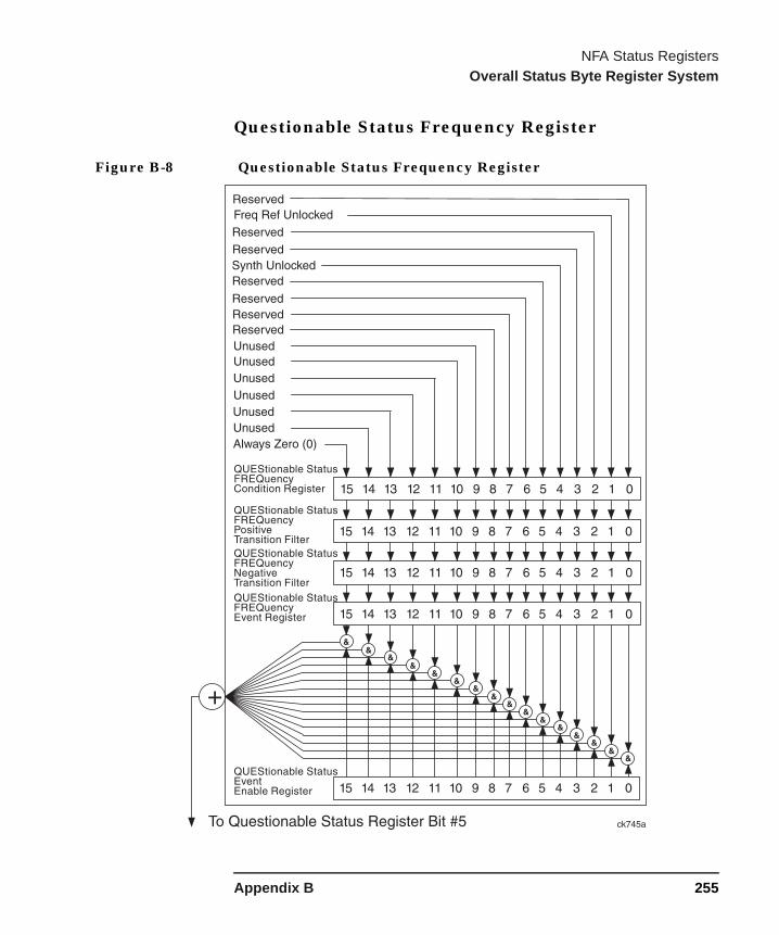
NFA Status RegistersOverall Status Byte Register System
Questionable Status Frequency Register
Figure B-8 Questionable Status Frequency Register
Appendix B 255
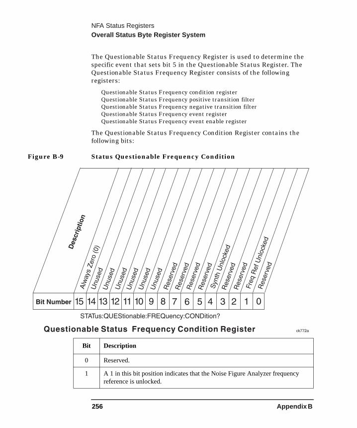
NFA Status RegistersOverall Status Byte Register System
The Questionable Status Frequency Register is used to determine the specific event that sets bit 5 in the Questionable Status Register. The Questionable Status Frequency Register consists of the following registers:
Questionable Status Frequency condition registerQuestionable Status Frequency positive transition filterQuestionable Status Frequency negative transition filterQuestionable Status Frequency event registerQuestionable Status Frequency event enable register
The Questionable Status Frequency Condition Register contains the following bits:
Figure B-9 Status Questionable Frequency Condition
Bit Description
0 Reserved.
1 A 1 in this bit position indicates that the Noise Figure Analyzer frequency reference is unlocked.
256 Appendix B

NFA Status RegistersOverall Status Byte Register System
or
The Questionable Status Frequency condition register continuously monitors output frequency status of the Noise Figure Analyzer. Condition registers are read-only. To query the condition register, send the command :STATus:QUEStionable:FREQuency:CONDition? The response will be the decimal sum of the bits which are set to 1.
The negative and positive transition filters specify which types of bit state changes in the condition register will set corresponding bits in the event register. The changes may be positive (from 0 to 1) or negative (from 1 to 0). Send the command :STATus:QUEStionable:FREQuency:NTRansition <num> (negative transition) or :STATus:QUEStionable:FREQuency:PTRansition <num> (positive transition) where <num> is the sum of the decimal values of the bits you want to enable.
The Questionable Status Frequency event register latches transition events from the condition register as specified by the transition filters. Event registers are destructive read-only. Reading data from an event register will clear the content of that register. To query the event register, send the command :STATus:QUEStionable:FREQuency[:EVENt]?
2,3 Reserved. These bits are not used by the Noise Figure Analyzer, but are for future use with other Agilent products.
4 A 1 in this bit position indicates that the Noise Figure Analyzer synthesizer is unlocked.
5–8 Reserved. These bits are not used by the Noise Figure Analyzer, but are ffuture use with other Agilent products.
9–14 Unused. These bits are always set to 0.
15 Always Zero (0).
Bit Description
Appendix B 257
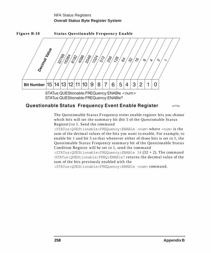
NFA Status RegistersOverall Status Byte Register System
Figure B-10 Status Questionable Frequency Enable
The Questionable Status Frequency event enable register lets you choose which bits will set the summary bit (bit 5 of the Questionable Status Register) to 1. Send the command :STATus:QUEStionable:FREQuency:ENABle <num> where <num> is the sum of the decimal values of the bits you want to enable. For example, to enable bit 1 and bit 5 so that whenever either of those bits is set to 1, the Questionable Status Frequency summary bit of the Questionable Status Condition Register will be set to 1, send the command :STATus:QUEStionable:FREQuency:ENABle 34 (32 + 2). The command :STATus:QUEStionable:FREQ:ENABle? returns the decimal value of the sum of the bits previously enabled with the :STATus:QUEStionable:FREQuency:ENABle <num> command.
Bit Number 789101112131415 6 5 4 3 2 1 02048
512
32
16 48 1
16384
8192
4096
1024
128
256
64
Decim
alValu
e
32768
2
ck773aQuestionable Frequency Event Enable RegisterStatus
STATus:QUEStionable:FREQuency:ENABle <num>
STATus:QUEStionable:FREQuency:ENABle?
258 Appendix B
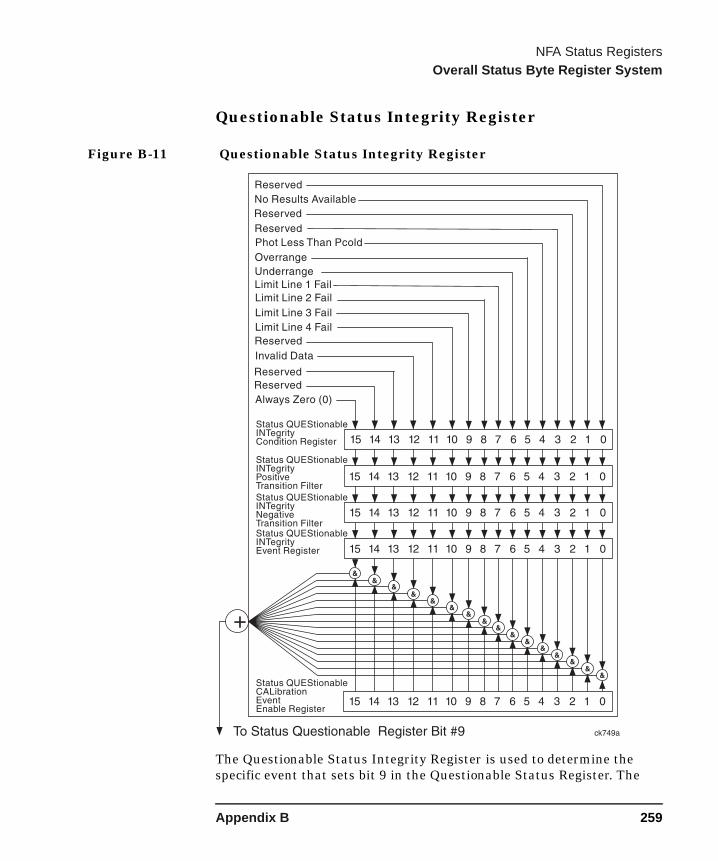
NFA Status RegistersOverall Status Byte Register System
Questionable Status Integrity Register
Figure B-11 Questionable Status Integrity Register
The Questionable Status Integrity Register is used to determine the specific event that sets bit 9 in the Questionable Status Register. The
Appendix B 259
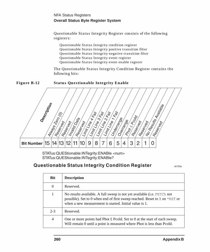
NFA Status RegistersOverall Status Byte Register System
.
Questionable Status Integrity Register consists of the following registers:
Questionable Status Integrity condition registerQuestionable Status Integrity positive transition filterQuestionable Status Integrity negative transition filterQuestionable Status Integrity event registerQuestionable Status Integrity event enable register
The Questionable Status Integrity Condition Register contains the following bits:
Figure B-12 Status Questionable Integrity Enable
Bit Description
0 Reserved.
1 No results available. A full sweep is not yet available (i.e. FETCh not possible). Set to 0 when end of first sweep reached. Reset to 1 on *RST or when a new measurement is started. Initial value is 1.
2-3 Reserved.
4 One or more points had Phot £ Pcold. Set to 0 at the start of each sweepWill remain 0 until a point is measured where Phot is less than Pcold.
260 Appendix B

NFA Status RegistersOverall Status Byte Register System
The Questionable Status Integrity Condition Register continuously monitors the status of the measurement results. Condition registers are read-only. To query the condition register, send the command :STATus:QUEStionable:INTegrity:CONDition? The response will be the decimal sum of the bits which are set to 1.
The transition filter specifies which types of bit state changes in the condition register will set corresponding bits in the event register. The changes may be positive (from 0 to 1) or negative (from 1 to 0). Send the command :STATus:QUEStionable:INTegrity:NTRansition <num> (negative transition) or :STATus:QUEStionable:INTegrity:PTRansition <num> (positive transition) where <num> is the sum of the decimal values of the bits you want to enable.
The Questionable Status Integrity Event Register latches transition events from the condition register as specified by the transition filters. Event registers are destructive read-only. Reading data from an event register will clear the content of that register. To query the event register, send the command
5 RF or IF overrange occurred at one or more points. Set to 0 at the start of each sweep. Will remain zero until a point is measured where either an RF or IF over range occurs.
6 RF or IF under range occurred at one or more points. Set to zero at the start of each sweep. Will remain zero until a point is measured where either an RF or IF under range occurs.
7-10 Limit line 1, 2, 3 or 4 has failed test (bits 7, 8, 9 or 10 respectively). Set to 1 at end of sweep if test fails. Remains set to 1 until measurement restarted or limit line type or test on/off state changed or limit line edited.
11 Reserved.
12 One or more points had an invalid measurement result. Set to zero at the start of each sweep/redisplay of data. Will remain zero until a point is measured where the required result type gives an invalid result e.g. log() of a negative number.
13,14 Reserved.
15 Always Zero (0).
Bit Description
Appendix B 261

NFA Status RegistersOverall Status Byte Register System
:STATus:QUEStionable:INTegrity[:EVENt]?
Figure B-13 Questionable Integrity Status Enable
The Questionable Status Integrity event enable register lets you choose which bits will set the integrity summary bit (bit 9) of the Questionable Status Register to 1. Send the command :STATus:QUEStionable:INTegrity:ENABle <num> where <num> is the sum of the decimal values of the bits you want to enable. For example, to enable bit 12 and bit 3 so that whenever either of those bits is set to 1, the Questionable Status Integrity summary bit of the Questionable Status condition register will be set to 1, send the command :STATus:QUEStionable:INTegrity:ENABle 5104 (4096 + 8). The command :STATus:QUEStionable:INTegrity:ENABle? returns the decimal value of the sum of the bits previously enabled with the :STATus:QUEStionable:INTegrity:ENABle <num> command.
Bit Number 789101112131415 6 5 4 3 2 1 0
2048
512
32
16 48 1
16384
8192
4096
1024
128
256
64
Decim
alValu
e
32768
2
ck756aStatus Questionable Integrity Event Enable Register
STATus:QUEStionable:INTegrity:ENABle <num>
STATus:QUEStionable:INTegrity:ENABle?
262 Appendix B
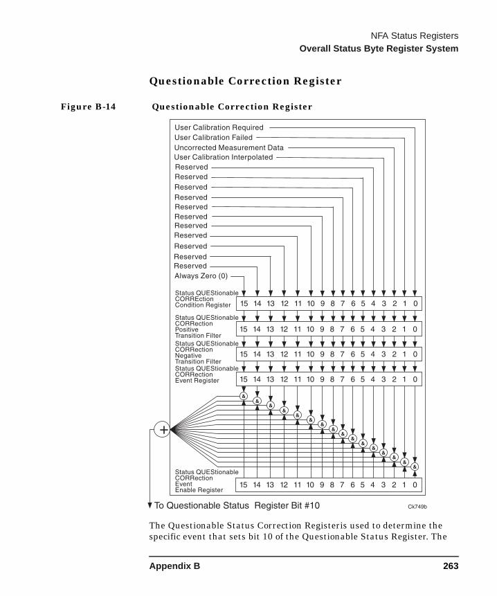
NFA Status RegistersOverall Status Byte Register System
Questionable Correction Register
Figure B-14 Questionable Correction Register
The Questionable Status Correction Registeris used to determine the specific event that sets bit 10 of the Questionable Status Register. The
Appendix B 263

NFA Status RegistersOverall Status Byte Register System
Questionable Status Correction Register consists of the following registers:
Questionable Status Correction condition registerQuestionable Status Correction positive transition filterQuestionable Status Correction negative transition filterQuestionable Status Correction event registerQuestionable Status Correction event enable register
The Questionable Correction Register contains the following bits:
Figure B-15 Questionable Correction Status Condition
Bit Description
0 User calibration is required (i.e. not done, or setup changed). Will remain 1 until a user calibration is done. Set to 1 at the start of a user calibration. It will go to 0 at the end of a user calibration only if at least all points on one range have been calibrated. Initial value is 1.
264 Appendix B
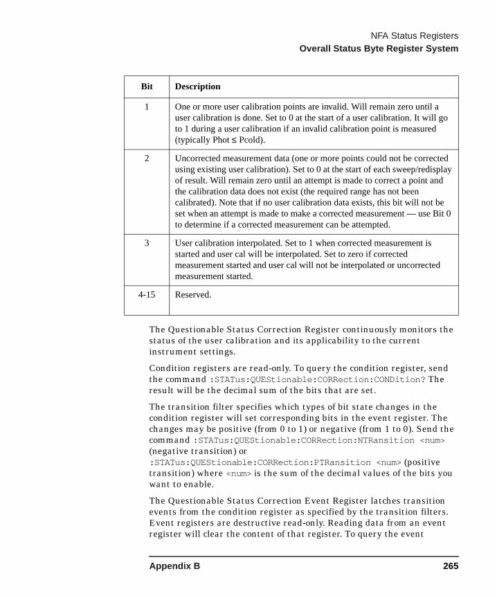
NFA Status RegistersOverall Status Byte Register System
it 0
The Questionable Status Correction Register continuously monitors the status of the user calibration and its applicability to the current instrument settings.
Condition registers are read-only. To query the condition register, send the command :STATus:QUEStionable:CORRection:CONDition? The result will be the decimal sum of the bits that are set.
The transition filter specifies which types of bit state changes in the condition register will set corresponding bits in the event register. The changes may be positive (from 0 to 1) or negative (from 1 to 0). Send the command :STATus:QUEStionable:CORRection:NTRansition <num> (negative transition) or :STATus:QUEStionable:CORRection:PTRansition <num> (positive transition) where <num> is the sum of the decimal values of the bits you want to enable.
The Questionable Status Correction Event Register latches transition events from the condition register as specified by the transition filters. Event registers are destructive read-only. Reading data from an event register will clear the content of that register. To query the event
1 One or more user calibration points are invalid. Will remain zero until a user calibration is done. Set to 0 at the start of a user calibration. It will go to 1 during a user calibration if an invalid calibration point is measured (typically Phot ≤ Pcold).
2 Uncorrected measurement data (one or more points could not be corrected using existing user calibration). Set to 0 at the start of each sweep/redisplay of result. Will remain zero until an attempt is made to correct a point and the calibration data does not exist (the required range has not been calibrated). Note that if no user calibration data exists, this bit will not be set when an attempt is made to make a corrected measurement — use Bto determine if a corrected measurement can be attempted.
3 User calibration interpolated. Set to 1 when corrected measurement is started and user cal will be interpolated. Set to zero if corrected measurement started and user cal will not be interpolated or uncorrectedmeasurement started.
4-15 Reserved.
Bit Description
Appendix B 265
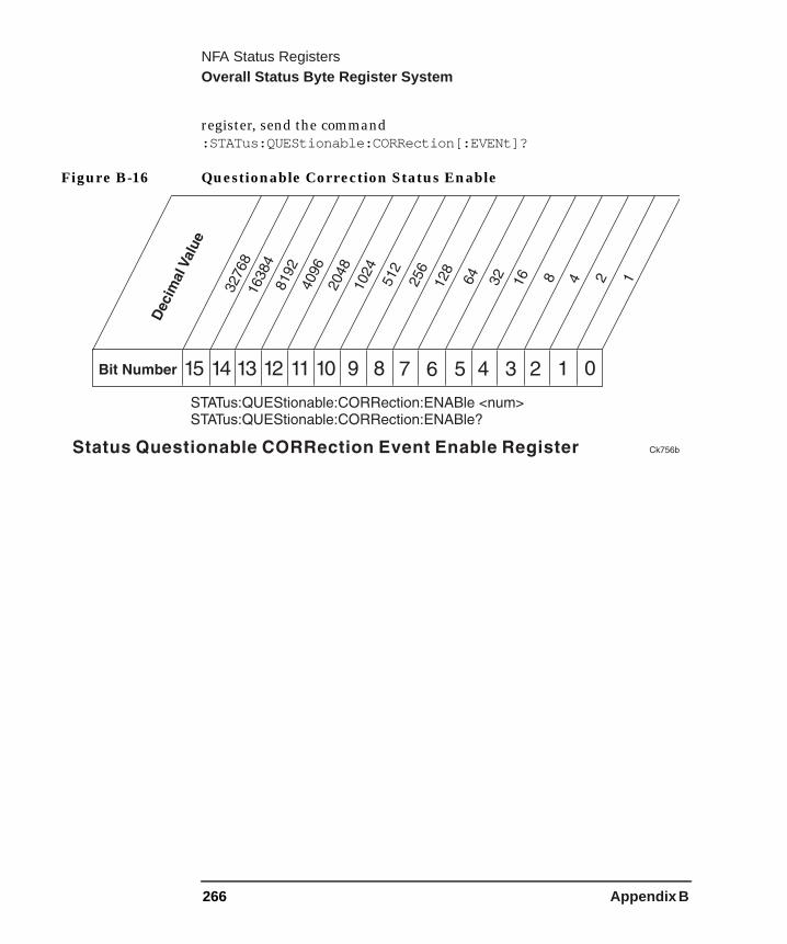
NFA Status RegistersOverall Status Byte Register System
register, send the command :STATus:QUEStionable:CORRection[:EVENt]?
Figure B-16 Questionable Correction Status Enable
266 Appendix B