Embed Size (px)
Citation preview

NATIONAL RADIO ASTRONOMY OBSERVATORY
GREEN BANK, WEST VIRGINIA
ELECTRONICS DIVISION INTERNAL REPORT No. 240
L-BAND RECEIVER:
INITIAL TESTS AT 18 cm AND 21 cm
H. E. PAYNE
DECEMBER 1983
NUMBER OF COPIES: 150
L-BAND RECEIVERINITIAL TESTS AT 18 cm AND 21 cm
H. E. Payne
TABLE OF CONTENTS
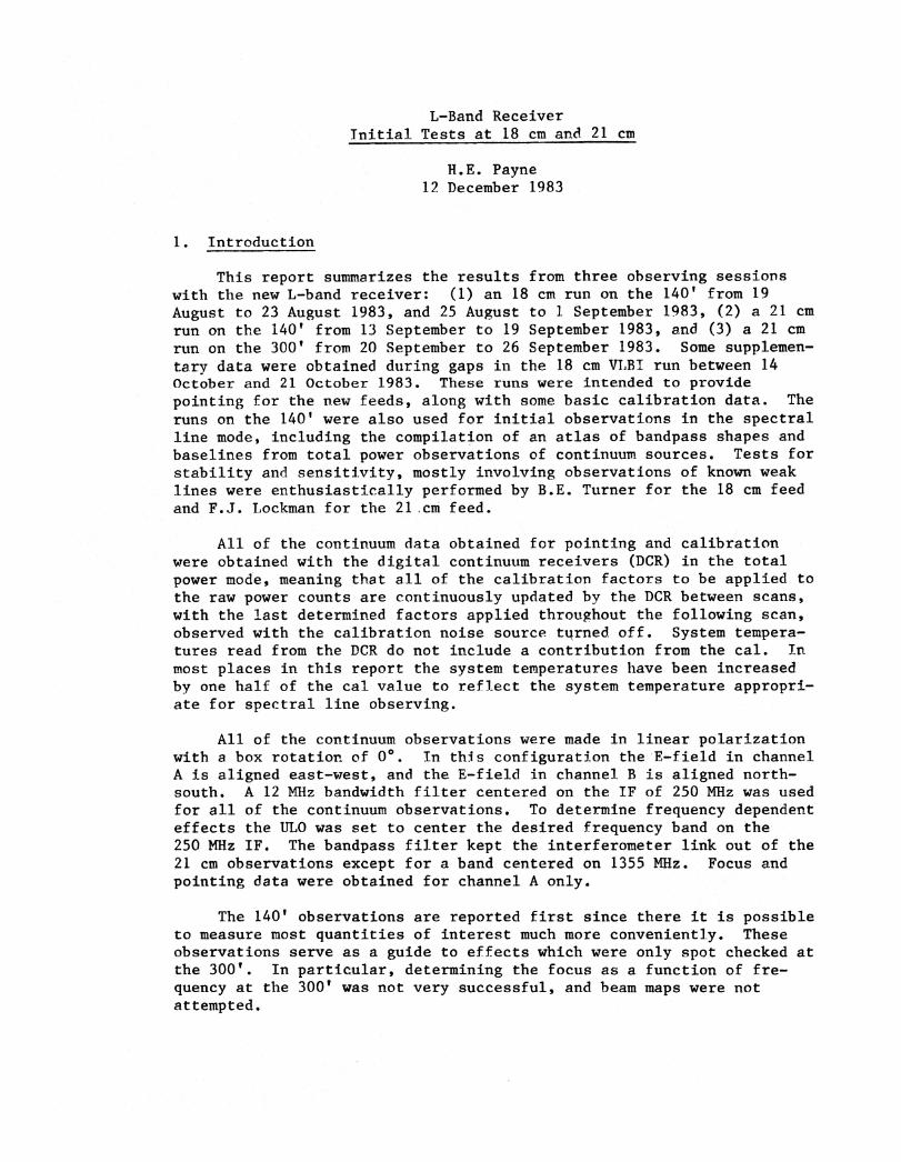
1. Introduction
2. 140' Observations
2.1. Pointing2.2. 21 cm Observations
2.2.1. 21 cm focus versus frequency2.2.2. 21 cm system temperature at zenith versus frequency2.2.3. 21 cm aperture efficiency versus frequency
2.3. 18 cm observations2.3.1. 18 cm focus versus frequency2.3.2. 18 cm system temperature at zenith versus frequency2.3.3. 18 cm aperture efficiency versus frequency2.3.4. 18 cm beam maps
3. 300' 21 cm Observations
3.1. Focus versus frequency3.2. Declination pointing3.3. System temperature at zenith versus frequency3.4. System temperature versus declination3.5. Aperture efficiency versus declination3.6. Beamwidth versus declination3.7. Aperture efficiency versus hour angle3.8. Sample results
L-Band ReceiverInitial Tests at 18 cm and 21 cm
H.E. Payne12 December 1983
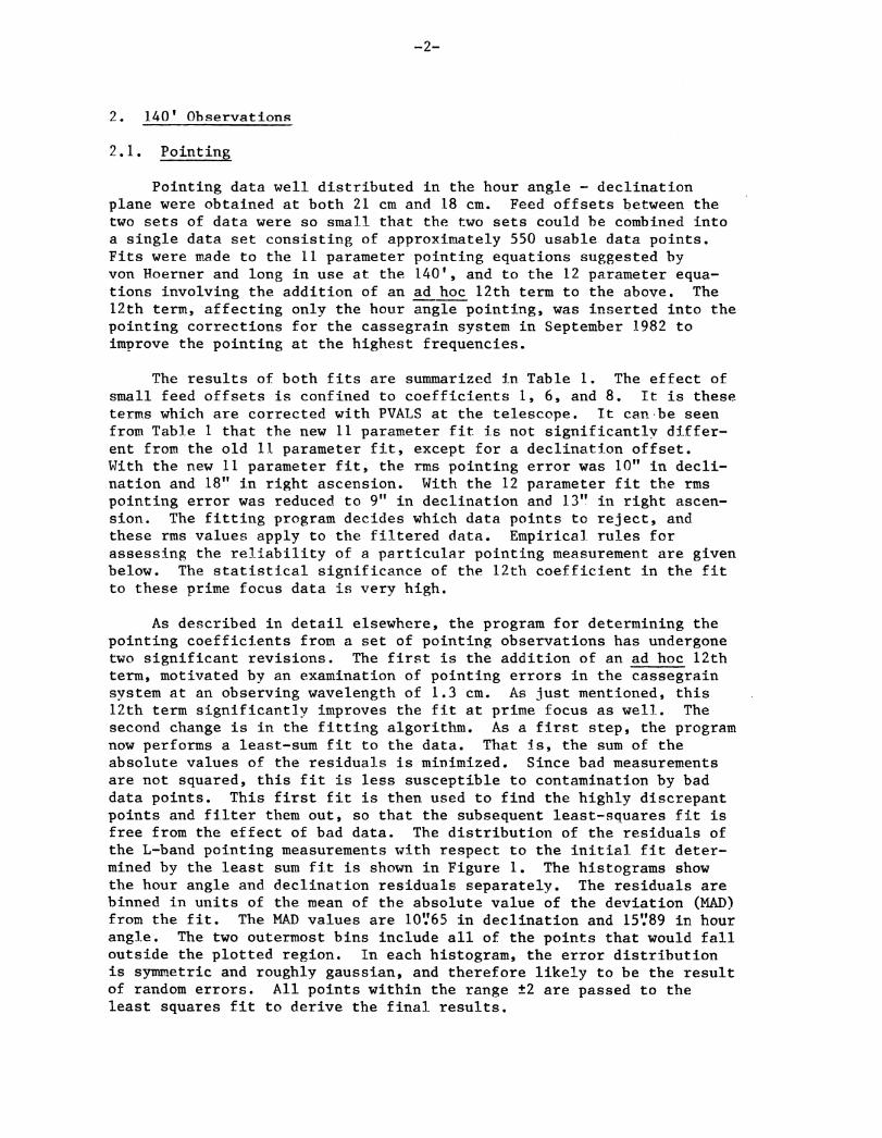
1. Introduction
This report summarizes the results from three observing sessionswith the new L-band receiver: (1) an 18 cm run on the 140' from 19August to 23 August 1983, and 25 August to 1 September 1983, (2) a 21 cmrun on the 140' from 13 September to 19 September 1983, and (3) a 21 cmrun on the 300' from 20 September to 26 September 1983. Some supplemen-tary data were obtained during gaps in the 18 cm VLBI run between 14October and 21 October 1983. These runs were intended to providepointing for the new feeds, along with some basic calibration data Theruns on the 140' were also used for initial observations in the spectralline mode, including the compilation of an atlas of bandpass shapes andbaselines from total power observations of continuum sources. Tests forstability and sensitivity, mostly involving observations of known weaklines were enthusiastically performed by B.E. Turner for the 18 cm feedand F.J. Lockman for the 21 .cm feed.
All of the continuum data obtained for pointing and calibrationwere obtained with the digital continuum receivers (DCR) in the totalpower mode, meaning that all of the calibration factors to be applied tothe raw power counts are continuously updated by the DCR between scans,with the last determined factors applied throughout the following scan,observed with the calibration noise source turned off. System tempera-tures read from the DCR do not include a contribution from the cal. Inmost places in this report the system temperatures have been increasedby one half of the cal value to reflect the system temperature appropri-ate for spectral line observing.
All of the continuum observations were made in linear polarizationwith a box rotation of O. In this configuration the E-field in channelA is aligned east-west, and the E-field in channel B is aligned north-south. A 12 MHz bandwidth filter centered on the IF of 250 MHz was usedfor all of the continuum observations. To determine frequency dependenteffects the ULO was set to center the desired frequency band on the250 MHz IF. The bandpass filter kept the interferometer link out of the21 cm observations except for a band centered on 1355 MHz. Focus andpointing data were obtained for channel A only.
The 140' observations are reported first since there it is possibleto measure most quantities of interest much more conveniently. Theseobservations serve as a guide to effects which were only spot checked atthe 300'. In particular, determining the focus as a function of fre-quency at the 300' was not very successful, and beam maps were notattempted.
-2-
2. 140' Observations
2.1. Pointing
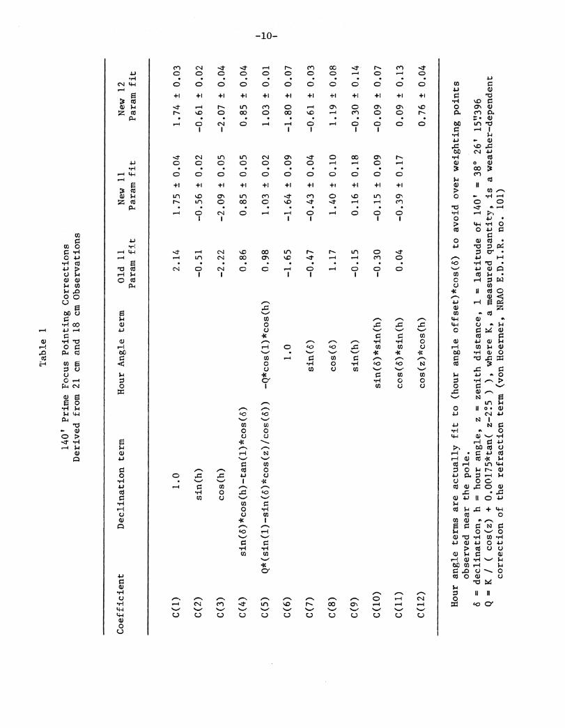
Pointing data well distributed in the hour angle - declinationplane were obtained at both 21 cm and 18 cm. Feed offsets between thetwo sets of data were so small that the two sets could be combined intoa single data set consisting of approximately 550 usable data points.Fits were made to the 11 parameter pointing equations suggested byvon Hoerner and long in use at the 140', and to the 12 parameter equa-tions involving the addition of an ad hoc 12th term to the above. The12th term, affecting only the hour angle pointing, was inserted into thepointing corrections for the cassegrain system in September 1982 toimprove the pointing at the highest frequencies.
The results of both fits are summarized in Table 1. The effect ofsmall feed offsets is confined to coefficients 1, 6, and 8. It is theseterms which are corrected with PVALS at the telescope. It can . be seenfrom Table 1 that the new 11 parameter fit is not significantly differ-ent from the old 11 parameter fit, except for a declination offset.With the new 11 parameter fit, the rms pointing error was 10" in decli-nation and 18" in right ascension. With the 12 parameter fit the tinspointing error was reduced to 9" in declination and 13" in right ascen-sion. The fitting program decides which data points to reject, andthese rms values apply to the filtered data. Empirical rules forassessing the reliability of a particular pointing measurement are givenbelow. The statistical significance of the 12th coefficient in the fitto these prime focus data is very high.
As described in detail elsewhere, the program for determining thepointing coefficients from a set of pointing observations has undergonetwo significant revisions. The first is the addition of an ad hoc 12thterm, motivated by an examination of pointing errors in the cassegrainsystem at an observing wavelength of 1.3 cm. As just mentioned, this12th term significantly improves the fit at prime focus as well. Thesecond change is in the fitting algorithm. As a first step, the programnow performs a least-sum fit to the data. That is, the sum of theabsolute values of the residuals is minimized. Since bad measurementsare not squared, this fit is less susceptible to contamination by baddata points. This first fit is then used to find the highly discrepantpoints and filter them out, so that the subsequent least-squares fit isfree from the effect of bad data. The distribution of the residuals ofthe L-band pointing measurements with respect to the initial fit deter-mined by the least sum fit is shown in Figure 1. The histograms showthe hour angle and declination residuals separately. The residuals arebinned in units of the mean of the absolute value of the deviation (MAD)from the fit. The MAD values are 10'.'65 in declination and 15'.'89 in hourangle. The two outermost bins include all of the points that would falloutside the plotted region. In each histogram, the error distributionis symmetric and roughly gaussian, and therefore likely to be the resultof random errors. All points within the range t2 are passed to theleast squares fit to derive the final results.

Since the program decides which data points to reject, an ex-amination of the rejected data gives a guide to the reliability ofpointing data This is especially useful for measuring PVALS, since asmall number of points is usually taken. Examination yields theseempirical rules:
An L-band pointing measurement for PVALS should be rejectedif:
1) you do not see the source in the scan, any of the fourprinted widths or heights is wildly different from theothers, or any other obvious deficiency,
2) the elevation is less than 10° for any source, if theelevation is less than 20
0 for all but the strongest
sources, and if the elevation is less than 300 for a weak
source,
3) if the two beamwidths measured by the right ascensionscans differ by more than 107,
4) if the two beamwidths measured by the declination scansdiffer by more than 107,
5) if the average of the two heights measured by the decscans is more than 10% lower than the average of the twoheights measured by the right ascension scans, or
6) if the average of the two heights measured by the decscans is more than 1/3 higher than the average of the twoheights measured by the right ascension scans.
2.2. 21 cm Observations
2.2.1. 21 cm focus versus frequency
Measured values of the nominal focus as a function of frequency areshown in Figure 2. Measurements refer only to channel A. The focus wasdetermined by the operator at each frequency in the usual way, which isto peak up on a strong continuum source, to record the total powerversus focus on the strip chart and then determine the midpoint betweentwo focus settings equally far down on the steep part of this curve.The measurements are repeatable to about -±1 mm. The source 3C 295 wasused for these measurements. The solid curve in the figure is not a fitto the data but simply a smooth curve drawn through the points. Thefigure is intended only to show the trend of focus versus frequencysince the focus should be checked for the frequency and bandwidth of aparticular observation.
-4-
2.2.2. 21 cm system temperature at zenith versus frequency
The system temperature at zenith as a function of frequency isshown in Figure 3. The system temperature in each channel varies byt2 K or roughly 8% across the observed frequency range. The systemtemperatures shown include one half of the cal value, as appropriate forspectral line observations. The cal values are shown if temperaturesappropriate to total power continuum observations are desired. Thefrequency of galactic HI lies near the minimum system temperature inboth channels.
2.2.3. 21 cm aperture efficiency versus frequency
The aperture efficiency n A is computed from the relationshipbetween flux density S and antenna temperature T
A for a point source:
nA = ( 2k/ A )*( T
A/S ),
where k is Boltzmann's constant and A is the physical aperture of thetelescope. For the 140', 2k/A is 1.930. The aperture efficiency as afunction of frequency is shown in Figure 4. The measurements arederived from observations of 3C 295, assuming the spectrum fitted byBaars et al. (1977, Astron.Astrophys. 61, 99), and assuming that thereis no variation in aperture efficiency with hour angle. Antenna temper-atures were derived from declination scans through the source as part ofthe peaking up procedure, after the proper focus had been determined.These aperture efficiencies are accurate to ±0.005 or better, but willvary with frequency and bandwidth. An aperture efficiency of 0.58corresponds to a gain of 0.30 K/Jy.
The shapes of the curves in Figure 4 closely mimic those of systemtemperature versus frequency. In particular, galactic HI falls near theminimum efficiency. That the efficiency rises toward the edges of thefeed bandpass may indicate a mismatch. The sensitivity to a pointsource, computed as the ratio of aperture efficiency to system tempera-ture, is shown as a function of frequency in Figure 5. This ratio isindependent of the assumed cal value, and since this figure is aimed atcontinuum observers, the system temperatures used do not include a calcontribution. There is little variation across the band but channel Bis about 15% less sensitive than channel A across most of the band. Forthe 140', if the ratio of aperture efficiency to system temperatureequals 0.025, then the time-bandwidth product necessary for a one sigmadetection of a one Jy source is 6000. An equivalent statement is thatthe difference between two ten second integrations, on and off a weakcontinuum source with a 20 MHz bandwidth, gives a flux density measure-ment with three sigma errors of 23 mJy.
1.1.0 ON.
2.3 . 18 cm observations
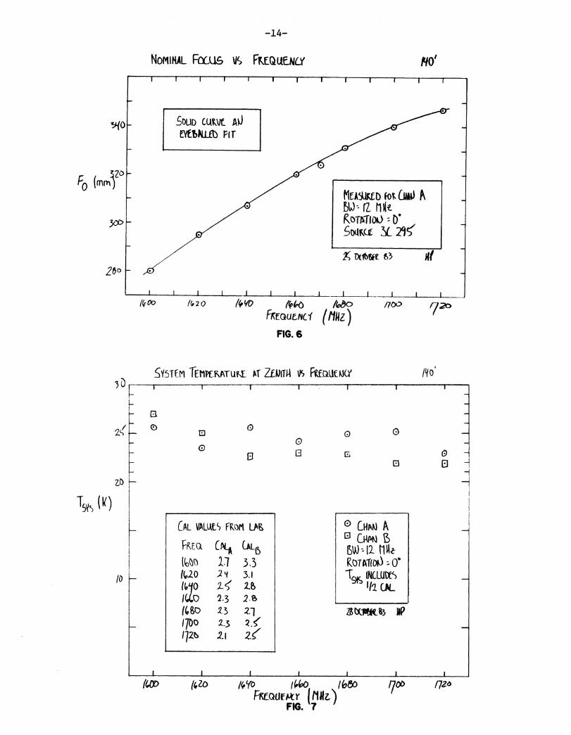
2.3.1. 18 cm focus versus frequency
The variation of nominal focus with frequency at 18 cm is shown inFigure 6. These measurements were made in an identical manner to thoseat 21 cm, even to the point of being measured on the same source. Inparticular, only channel A was measured, and the solid curve in thefigure is not a fit but simply a smooth curve drawn through the data.
2.3.2. 18 cm system temperature at zenith versus frequency
The system temperature at zenith as a function of frequency at18 cm is shown in Figure 7. The system temperatures shown include halfthe cal value. Channel B shows a larger variation across the band,about t2.5 K or t107.
2.3.3. 18 cm aperture efficiency versus frequency
The aperture efficiency at 18 cm shows little variation withfrequency, as shown in Figure 8, except for a decrease at the highfrequency edge of the band. Both curves vary around a value near 58%.That the system temperature and aperture efficiency versus frequencycurves are not as smooth as those at 21 cm may reflect largeruncertainties in the cal values. The cal value independent ratios ofaperture efficiency to system temperature (without a cal contribution)are shown in Figure 9, and are quite smooth. At the OH main linefrequency, channel B is about 10% more sensitive to a point source.
2.3.4. 18 cm beam maps
Beam maps were made at a frequency of 1660 MHz, with a bandwidth of12 MHz. Two contour maps, Figures 10 and 11, show the inner sidelobestructure measured against the very strong continuum source 3C 274.Contours are plotted at 2 db intervals. The vertical bar in the figuresis 1° in length. Scans across the source were spaced by 9', and 10scans were used to obtain the figures shown. The contour plottingroutine only compares neighboring scans, rather than fitting a surfacethrough the data, and this gives rise to the horizontal edges whichappear in the figures. The sidelobes form a cloverleaf pattern alongdiagonals through the field. The sidelobes are about 18 db down fromthe peak of the main beam, and are separated by about 28' from the peakof the main beam. A weak plateau joining the two northern sidelobes,and another joining the two southern sidelobes is found in channel A.In channel B the plateaus are in the east-west directions. The po-sitions of the sidelobes themselves are not very different between thetwo channels. In channel A the main beam measures about 19.1' EW by16.8' NS, so that the main beam is narrower in the directions where theplateaus are evident. In channel B the main beam measures about17.0' EW by 19.0' NS.
-6-
3. 300' 21 cm Observations
3.1. Focus versus frequency
An attempt to confirm the focus versus frequency behavior observedon the 140' was not very successful. I sought that focus which min-imized the east-west half-power beamwidth measured by drift scans acrosspoint sources within about 25° of the zenith. The first measurementswere at 1405 MHz, and gave -305 mm in channel A and -380 mm in channelB. The accuracy of these measurements is perhaps t25 mm, poor comparedto the 140'. The channel B data seemed somewhat better, so a compromiseof -360 mm was used for the pointing run. Measurements at 1365 MHz and1385 MHz gave about the same results. The data at 1425 MHz were poorand the results inconclusive.
Measurements by R. Giovanelli and M. Haynes in November 1983, againonly in channel A, do confirm the trend measured on 140' over the rangeof 1370 to 1400 MHz. Their measurements would indicate that the bestfocus at the 300' is roughly 740 mm lower than shown in Figure 2.
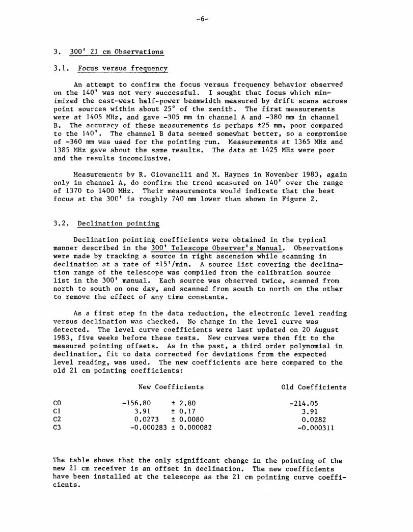
3.2. Declination pointing
Declination pointing coefficients were obtained in the typicalmanner described in the 300' Telescope Observer's Manual. Observationswere made by tracking a source in right ascension while scanning indeclination at a rate of ±15'/min. A source list covering the declina-tion range of the telescope was compiled from the calibration sourcelist in the 300' manual. Each source was observed twice, scanned fromnorth to south on one day, and scanned from south to north on the otherto remove the effect of any time constants.
As a first step in the data reduction, the electronic level readingversus declination was checked. No change in the level curve wasdetected. The level curve coefficients were last updated on 20 August1983, five weeks before these tests. New curves were then fit to themeasured pointing offsets. As in the past, a third order polynomial indeclination, fit to data corrected for deviations from the expectedlevel reading, was used. The new coefficients are here compared to theold 21 cm pointing coefficients:
New Coefficients Old Coefficients
CO -156.80 t 2.80 -214.05Cl 3.91 t 0.17 3.91C2 0.0273 t 0.0080 0.0282C3 -0.000283 ± 0.000082 -0.000311
The table shows that the only significant change in the pointing of thenew 21 cm receiver is an offset in declination. The new coefficientshave been installed at the telescope as the 21 cm pointing curve coeffi-cients.

_7_
3.3. System temperature at zenith versus frequency
The variation of system temperature at zenith with frequency isshown in Figure 12. The shape of the dependence for each receiver issimilar to that found on the 140', shown in Figure 3. Note, however,that the range of plotted temperatures in Figure 12 is 10 K to 40 K, incontrast to 0 K to 30 K in Figure 3. The system temperature in channelA is roughly 9 K higher than measured on the 140' in the middle of thefeed bandwidth, and the system temperature in channel B is roughly 5 Khigher. The behavior at the edges of the feed bandwidth is slightlydifferent. Especially noticeable is a large increase in the systemtemperature for channel A at 1435 MHz.
Giovanelli and Haynes measured the system temperature during theNovember 1983 installation and found much lower values, about 23 K,assuming a slightly smaller aperture efficiency, resulting in slightlysmaller cal values. Using the cal values measured in the lab, as duringmy tests, would give temperatures around 25 to 26 K. The system temper-atures were determined from spectral line observations with a 10 MHzbandwidth. During the November installation, R. Norrod measured 27 to29 K, using the DCR and adding one half of the cal. It appears that thediscrepancy between these system temperatures and those T measuredearlier is due to a change in the receiver between installations. Thecal values measured in the lab did not change between the two instal-lations.
3.4. System temperature versus declination
The system temperature data shown in Figure 13 were obtained byscanning the telescope in declination, recording the system temperaturecalculated by the DCR on the chart recorder. Declination marks were puton the record. The data shown are actually a composite of two suchscans, widely separated in time, one of which saw the galactic plane athigh declinations, and the other of which saw the galactic plane at lowdeclinations. There was, however, an offset of about 1 K between thetwo scans, perhaps due to an error in setting up the chart recorder.Also, the measured points need to be raised by about 1.2 K to intersectthe system temperature versus frequency curves of Figure 12.
3.5. Aperture efficiency versus declination
As described above, the aperture efficiency nA can be determinedfrom antenna temperature measurements of point sources with known fluxdensity. Antenna temperatures were determined from drift scans across aset of sources spanning the declination range of the 300°. Sourcepositions and fluxes were taken from an Appendix to the 300' Telescope Observer's Manual. The ratio ( 2k/A ) is 0.4203 for the 300'. Theresults for channel A are shown in Figure 14, and those for channel Bare shown in Figure 15. In each case the solid curve is the best fitquadratic polynomial in declination. To allow comparison, the two fitsare shown together in Figure 16. The top curve is channel B. The twofits are

-8-
Channel A:A = 0.434 + 0.00430*6 - 0.0000565*62
Channel B: 71A = 0.499 + 0.00289*6 0.0000431*62
In contrast to observations on the 140', the aperture efficiency ishigher in channel B than in A. The peak efficiency in each channel islower than it is on the 140'. On the 300', an aperture efficiency of0.54 corresponds to a gain of 1.28 K/Jy.
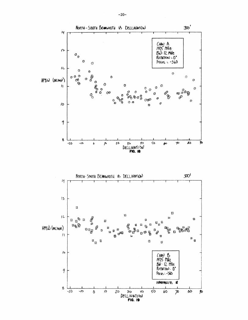
3.6. Beamwidth versus declination
Since beam mapping is quite tedious on the 300', the only conve-nient measure of the beam shape is the half-power width of the main beamobtained by scans across the source. North-south scans used for decli-nation pointing and east-west drift scans used for aperture efficiencymeasurements provide a large sample of such data. The results forchannel A are shown in Figures 17 and 18 and the results for channel Bare shown in Figures 19 and 20. Above 10° of declination all fourcurves are flat, yielding beam shapes of 9.6' EW by 10.4' NS for channelA and 8.9' EW by 11.3' NS for channel B. The beam in channel A degradesat declinations below 10°, as confirmed by the more rapid loss ofaperture efficiency shown in Figure 16.
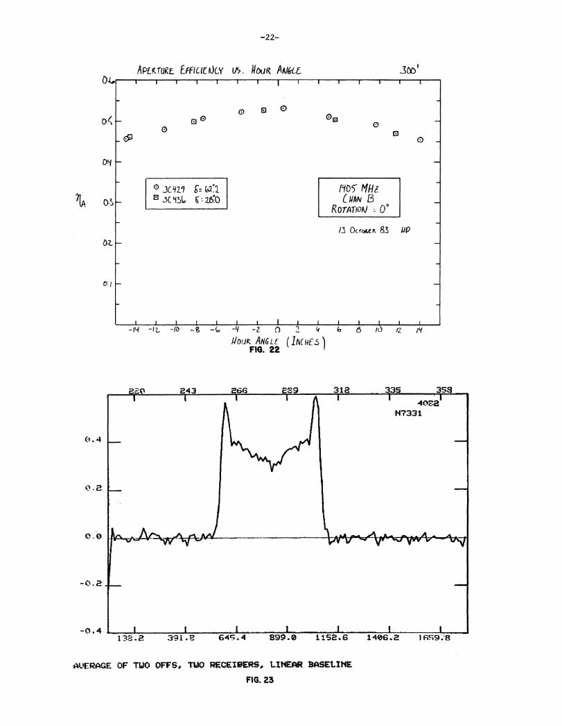
3.7. A erture efficienc versus hour angle
Aperture efficiency as a function of hour angle was something thatwe were able to measure, using the DCR and the strip chart recorder,while the off-line computer was down. While tracking in hour angle, theoperator (R. Davis -- thanks Rick) dialed in a declination rate to drivealternately north and south across the source while I used a battery anda switch to put hour angle marks on the strip chart. By measuring theheight and position of the peaks in the resultant strip chart record theantenna temperature, and therefore aperture efficiency as a function ofhour angle can be determined. The tracking in hour angle was slowenough that any time delay in the detectors and recorders was negligi-ble. We made measurements on a single receiver channel at a time. Foreach channel we tracked two sources, fortuitously at roughly symmetricalpositions on the aperture efficiency versus declination curves. Theresults are shown in Figure 21 for channel A and Figure 22 for channelB. As better shown in Figure 22, the aperture efficiency at the travellimits of the Sterling mount drops to about 85% of its on axis value.
3.8. Sam le results
To demonstrate the properties of the receiver during actual obser-vations, I observed a small subset of the Tully-Fisher sample of gal-axies. The recent compilation of spectra from their survey served as abasis for comparison. Sample results for NGC 7331, NGC 7721, andNGC 7218 are shown in Figures 23 to 25. Each of these galaxies wasobserved with a 10 MHz bandwidth. Total power off scans were obtainedboth before and after the op source scan, and were averaged together.

The results shown are the average of both polarizations. A linearbaseline has been removed, but there was very little slope in the rawbaseline, as well as no noticeable curvature. A cal value of 4.00 K wasused for all of the observations, which is an overestimate. In thefigures, heliocentric velocity is shown on the horizontal scale.
Tab
le 1
140' P
rim
e F
ocu
s P
oin
ting C
orr
ecti
ons
Der
ived
fro
m 2
1 c
m a
nd 1
8 c
m O
bse
rvat
ion
s
Co
effi
cien
tD
ecli
nat
ion
ter
mH
our
Ang
le t
erm
Old
11
New
11
New
12
Par
am f
itP
aram
fit
Par
am f
it
C(1
)1.
02.
141
.75
± 0
.04
1.7
4 ±
0.0
3
C(2
)si
n(h
)-0
.51
-0.5
6 ±
0.0
2-0
.61
± 0
.02
C(3
)co
s(h)
-2.2
2-2
.09
± 0
.05
-2.0
7 ±
0.0
4
C(4
)si
n(0
*co
s(h
)-ta
n(1
)*co
s(d
)0.
860
.85
± 0
.05
0.8
5 ±
0.0
4
C(5
)Q
*(s
in(1
)-si
n(6
)*co
s(z)
/co
s(6
)) -
Q*
cos(
1)*
cos(
h)
0.98
1.0
3 ±
0.0
21
.03
± 0
.01
C(6
)1.
0-1
.65
-1.6
4 ±
0.0
9-1
.80
± 0
.07
C(7
)si
n(6
)-0
.47
-0.4
3 ±
0.0
4-0
.61
± 0
.03
C(8
)co
s(6)
1.17
1.4
0 ±
0.1
01
.19
± 0
.08
C(9
)si
n(h
)-0
.15
0.1
6 ±
0.1
8-0
.30
± 0
.14
C(1
0)si
n(d
)*si
n(h
)-0
.30
-0.1
5 ±
0.0
9-0
.09
± 0
.07
C(1
1)co
s(5)*
sin(h
)0.
04-0
.39
± 0
.17
0.0
9 ±
0.1
3
C(1
2)co
s(z)
*co
s(h)
0.7
6 ±
0.0
4
Hour
angle
term
s are
actu
all
y f
it t
o (
hour
angle
off
set)
*cos(
) to
avoid
over
weig
hti
ng p
oin
tso
bse
rved
nea
r th
e p
ole
.d =
decli
nati
on, h =
hour
angle
, z =
zenit
h d
ista
nce, I
= l
ati
tude o
f 140' =
38°
26' 1
5'.'
396
Q =
K /
( c
os(
z) +
0.0
01
75
*ta
n(
z-2
°5 )
),
wh
ere
K,
a m
easu
red
qu
anti
ty,
is a
wea
ther
-dep
end
ent
corr
ecti
on o
f th
e re
frac
tio
n t
erm
(v
on
Ho
ern
er,
NR
AO
E.D
.I.R
. n
o. 1
01
)

hCU
R A
NG
LE R
ESID
UALS
rECLI
NATIO
N R
ESIO
LALS
IN U
NIT
S C
F P
EAN
AeSCLU
TE D
EVIA
TIC
NIN
WIT
S 2
P Y
EAN
AFSCLU
TE D
EVIA
TIC
N
I____I_
___I_
___I_
___I_
___I_
___I_
___1____I_
___I_
___I
..*******************************************
I*************
1**
1***********
1***
****
-********
i***
*1*
****
**I*
*************
I*********
-*******
-1************
1 *************
I*****************
1 *********************
.-***********
i***
****
****
*i*
****
****
****
****
i***
****
****
**1*
****
****
****
****
****
-***********************
-1*
****
****
****
****
****
**I*****************************
1*******************************************
I*******************************
....**************************************************-
1*************4:*
**********************
1**************************************
1******************************************
1 **************************
-***
****
****
****
****
****
.-I*
****
****
****
****
****
****
**i*
****
****
****
****
****
***4
:**
i***
****
****
****
****
****
****
****
*i*
****
****
****
****
*-*
****
****
****
*1 *
***********
1. ********t'-e
***
I********
1***
***'
**-*
**
1 **
1**
2.5
0 ..*
******************
----
I____A____1,....-
.71--
7-1
-717.-
--1-_
__
-71
35-2
.50 -
********************.*
**
****
-26
111*
**I
.. 3
21*
**i
39
i****
1..
4b
I*******
I7
7-2
.00
. •..
......
......
......
......
......
......
......
......
......
......
......
......
......
......
......
......
......
......
......
......
......
......
......
......
......
......
......
......
.... -
......
......
...'5
41*
**I
36
1***
*I
4.12
1***
****
I7
91*
**.*
*I
56
-1.5
0 -
*****
_5
10i*
*****
I' 6
11i*
***********
I:11
141*************
I12
17f*
***********
111
9-1
.01 -
*******************
-17
10f*
*****************
4-16
141*
***.
****
****
**1
1.311
1******************.*
*1
1817
i************************.*
******
• 1...
2819
-c.5
0 -
*********.*
*************.*
***
-24
1Gi*
********.*
******.*
***.*
*****
123
24i*
***************************
125
351*.*
******************
*************
131
25i*
************************************.*
*1
.3.5
4Cc.
00 -
**********************t*
****************.*
********-
4430
1****************.*
************
126
31i*
******.*
:*************************
..13C
341*************
***************:*
****
131
211*
*******.*
****.*
******
119
IG0.5
1 -
******************.*
********
-24
22
te.:
.***
*'**
****
****
****
*-**
*I
212
21*******************
117
.26
i********.*
************
IIC
15[4
,***
****
****
**...
113
121.0
0 -
*******
-7
lc1*
.**.
**1
512
1.************
111
71.*
***********.*
*1
137
i********
1IC
31.5
0 -
******.*
*****
-11
4i*
***.*
*****
I9
tI
I4
31*
**I
3-
21:
::I
1.a
.2.0
0 -
*-
1. I
1**
I2
.. 2
1-**
I2
2I..
'I
c
oi*
.I
116
- ..
••2.. ..50. -*
*************************
-23
1_-
___1_1.---
1--
--1--1
----
1--
__I-_
_-1
-_--
____1
-2.5
0
-2.0
0
-1.5
0
-1.0
0
-0.5
0
0.0
0
0.5
0
1.0
0
1.5
0
2.0
0
FIG
UR
E 1

SoLID Vf- A14elf_fiLL HT
tiasuriD Gok)12_ Mt
Kt-rAnoo,Qb
Coack 3C 2)
s outwit n
/37b Noo IN
RENEW& ( MOFIG. 2
IVeo1
/YIN/Y.50370 /380
-12-
NOMINAL FOC,u5 v5 Ftto.UNC?
r D (nip.)
_SYSTEM TEMPLKAfUKE AT ZENITH I/5 REQUOWY
El B
1:1
‘-)
CuANL=I- Cum BKwrtitioo = 0[SW = 12 111-1TMS INCLUDES 1/2 CAL
/3 Data 83 JIP _
P120 /y30 Ny0
f:f rc.I(ALA ( ILt
LN5 . Dr) )./375 3.B9 5. 6113B 3.72 q.101375 3.7 L1.17
/LIDS 75 .312
1 q 15 3 62 3.8337t
193 5.114 1.14)
lyso (sip rico ntoFREQUENCY (NH?)
FIG. 3

—13—
NO/APERTURE EFFICIEACi 1h. ktUtt.NLY
CI
0■•■•■■I
0 I
64
•■•■■•••1
o3
01
1.■••
o CHAR A
• C4AtiEV-- 12 MAZROTATNI = 0°
ig caw
BASED ON 065f(VA11005 Of 3C. 2.1SFLUX V5. FIC14 ROA 8API6 ff AL.1171 fk5it%). N51 CYN‘)(7. 611(11
NEll FLUX (Ji)
13 6C I22. LI
13 g5 2253
1515'IW
2-Z.1SN? 22 Nl'Ff; 21.
•■••••
1301
06 /Y10FKEDUENCY (MO%
FIG. 4 •
iyzo ry_50 /60
POItiT .SoURcE _SENSITIVITY V5. FREQUENCY0 03
00
0 El0 E3 O II
0 oz_
.)1A/T.5Y5
0,01
° CRAN AHAN B
B\A) 2 MHz.ROTATION z- 00
DDE5 NOTINCLUDE A CALCORSI oN
LE., TOTAL RUM
/8 aron a5 tie
t ypo two /so / 7() /yo6 i‘YtoFREQUENCY 141-1Z )
iy2o typo
9{0
mor
260
SDUD ant AOMINA) PIT
CY51(11 TEMPERATuf\E AT ZLIKI4 Vs RECILIOJCII NO'
El
•■■■■■•1
CAL 01_4,5 EOM LAE
RED, (ALA bat
(UP /I 3.3t 2O 24 3.1
2.< 2.61140 2-3 2.B
MD 23 2.11700 2.3 2.<112b 2.1 2.(
CHAm ACAKI
1SW--12.OTATOOT Mitts
119.
2801otit IW
••■■••1
1
-14-
NOMINAL FOC,U6 11') FREQUENCY
MEASUKED foT, (JIM)bti-- 12 M.Konfrio0 = 0°_Coo&ce 24‹
Dttrit 63 iii
I
As 2 0 /4.1/0 to‘Po , /(obo‘Frroutsvci ( /111z )
FIG.6
_L____ 1 I I j J I 1
/700
W(I) tkv0REGILIF r (Mit
FIG. 7
ZO 0780 1706 1726

1
0
0El
/7207
Ltio0 AtJ Cpioli8t,) -- 12 mitKo-rAnbA A
imciacins
I 1 1 1
&co /4020 /470 1446 , , 480krQuENLY ilni
FIG. e
1 i_.. 1. .1_ I
O.
O'S
o,(
BASED ON 0165tVATINIS IX _1215Falk VS,FICECL bPARs Ei AL
1117, A5KtO ASIKONS. CA, 11,
RE.o, n_ux (JY
ib001OPHo tto 11.qt166 /1 211680 1/ 071700 18 81
1726 /6 66
isro /449FKEQufoicrFIG. 9
/ 80 170o zo/ co
APE UTE Erf Oel kV) Fic EINE OCY
POINT (.3,)0KCE SE135Iiltilr( VS FqQ0CAte
ElEl
0
0 Caw AEl Cutio19A - 12 hittRoTATI00 obT5,6 Doe-, AXT
1NCLUDL ACM,
CoknKtf-mooki
2B
'OS
0.

-16-
b i 212A.
N /3 4 4
N 12 47
37.81334 120 91 77 63
11•11MINI.
ONNINOMIN.
1.2 30 PS_ ■■••••••••■
18 cm
-
N 13 21249gg 37 81E34
N /3 4 44_A
0N 12 47 I?
12 30 P
120 101E? 91
■•■••••■■■
18 cm
12 31 13. 30 4. 28 54. 27 44.RIGHT ASCENSION
Channel B: 2 dB contours, lowest is -24 dB.
FIG. II
77 63
25 24.26 34.
•■•••••■
12 31 13 . 3e) 4 . 28 54 . 27 44. 26 34. 25 24.VIRGO RIGHT ASCENSION
Channel A: 2 dB contours, lowest is -24 dB.FIG. 10

CI
° CHAN ACHAN a
1 b1P -TioN r)-T5 se5 Ji 1/2 CAL
Oc1on r e1/4 61
CI
)01
-ZO —to x) 3O qo
DEcutJt-no0FIG. 13
-17-
LtOSYSTEM TEMPEKATURE AT ZENITH V. PREQUEACY 3001
I I
0
)6(c() 1 7 iS do oo l oo iy.fo #Y0
FkEati F NC ( MHZ \\
FIG. 12
SYSTEm TEIIPM146_ DiatiARDO
1.0
0-10
0 0o
0
00
® CHAO A
El CUAU
11105
13W-- (2_ NitKOTATIDO-_
Ty5 tAtLItSI/2 CAL-
31 tx_IONEB Ve
T(K)

0.‘
0 k
0.
P/0
71A
APERTURE EFFICIENCY \IS DECLINATIONI 0 (°' I g
0 °
300/
SOLID CURVE 15 BEY( FITMIADKATIC POLYNOMIAL
IN DECLINATION
CHAN e)1q
05 MHz.Mid iz z.
ROTATIN 0°
—18—
3001APERTURE EFFICIENCY V5 DECLINATION
SOLID LURVE 15 THE UST AT
QUADRATIC_ POLmoNsit IN
DECLINARON
Oal1405 tlfiaBld 12 Mtg
o-rAimJ Ob
bLibbelk al 4f
I 1 I I I _i_____ I I i 1 I
--zo -JO 0 0 2) 30 yo co 0
DECLINATIONFIG. 14
03
6 z
0
Ds(
0 'I
- 13 NTOESEK 83 ge
•■•■11
11A 03
02
0.1
I I I I I i I I I I I —tob lb 2ks 36 IP 56 0 -X. 80
DECLINATIONFIG. 15

1 I I
0000
_ 0000
00 0
o 0
0
0
CuA))
no) MitISO - IL 144t
Kg tti Y
itLUS , -56O
ttAtt4bit63
0
0
64,0
c9or ccP6 cf3° o
-19-
3C01APERTURE EFFICIENCY V.S. DECLINATION
CUM CS
CRAM A
jLf MI-lz13W MkROTATION 0°
D.3Q',1Ars)RATIC F(T5 77) DATA:
A 11A=
L.1.50.63‘ -
1,■■••••13: /IA = 9.31.10-4
XTWER 65 UP
0 (
1 1 I J t 1 1 1
lb zo 60 70 80
DELLMAT (ONFIG. 16
1
-20
EACI Vit t .1 15040 1 D-fa us 1 t1t_WAT1o0
I I i I t r r I I 1
-ID /0 20 3t• Yo So (;t5 7, 8 P
DECLIPKINFIG. I'T
0
t731:1
1:1 65)
rib (a)0 (30
ca (?3 0 o
Go (43 apD
0 Do as, or, 0
-20-
NaTa-Satru Lb/4MM I/5 DrC/ mletrib01,1
oo
Cully AP1KttBO, IZ.fideK0TAT100 Ob
FOcus c
0
00
0 o 0 o,o o 00 0 o (Pa, co 0 w9
o °93(60g ° co o(Zo) 0 or)
0 0 0) oo
11M (fiukI))\i
ID
0
S I I I I I I 1 I I 1 t
-10 '10 6 ft. Z 6
3.b. fD CO Oo r SO
DECLI VATS 6IJFIG. 18
NOUN - SNITIt BEAmmula DEctiOg
ior) 300
)3
1-11t6 (AtOs.ut3)
80ArtVikt.% ifI I I
-2,0 -to 6 )0 Zo ,t7 Y co 0 70 66DE(1,10P/o0
FIG. 19

0 0000000 a9
•
'D 0O °0
0
0 '1
71A
e 4i6• 1.107
0.2
1 1/05 MHzCHAO tA
R 071vifOiki = 0°
12
n5ft
-21-
EAS1 - WEST 6EAWItYill v DECLI At AT 01J
I 1
3CO'I `t
5
i t
Cou
NY- IL MkKoTATI00'fouv,
IN (wool)bleDtti,53
ti
10k 0 oo
0.6
0Cf
w19, agcco
-ro "D 10 So ito
Decui3-no0FIG. 20
APEkT-LIKt yty HOU& ANGLE
--T 1
0
çt
0 o(43 0
4,0 70 qt5
3001
0.•0
0,1
I I I I I L L__L t j t I I I I -N -8 -L -Li -2, 0 2_ 1-1 C. O i0 lz 14
HOUK. ARGLE (INCLIE
FIG. 21
00.<
° 3012.1ti 3C LIIL E z0
0
0
//05" MHzCuttry B
ROTATIDN = 0°
/3 OCCOAE it 83 IV
62_
o.t
ra /Y/2-z n 2 4
ii0C/K ANGLE (11CiE5)FIG. 22
2E0 243 266 312 33S 353I
,......._r- .4(y2'
117331
. 4
2
0.0
-0. 2
1■•••■••■
-0.4 I I I _
138.2 391.8 645.4 S99.0 1152.6 1406.2 16s9.13
£39
-22-
APEK TORE EffICIE OLY th liOuR AWE 3601
AVERAGE OF TWO OFFS, TWO RECEIBERS, LINEAR BASELINE
FIG. 23

335220 243 266 289 312
-23-
0.16
. t-8
0. 4 0
1505.9 1760.5 2015.0 2269.5 2-24.1
0.,.
-0 . t. 4
OVERAGE OF TWO OFFS, AVERAGE OF TWO RECEIVERS, LINEAR BASELINEFIG. 24
220 243 2136 imp 312 335 358r4079
N7218
. . . .E9;4 . 3 11E3.5 140.'1.7 1662.0 1916.2 2170.5 i7:4a4.7
AVERAGE OF TWO OFFS, WO RECEIVERS, LINEAR BASELINEFIG. 25