Embed Size (px)
Citation preview

No. 121 SPRING 2018

Compete at a higher level.
In an industry where success is about profits as well as performance, you want to trust a partner who can lift you to the next level.
Grace custom catalyst solutions, co-developed with you, are about more than chemistry. They’re designed to lift your financial performance.
In some cases, the difference between our refinery customers’ financial return on Grace technologies versus the alternative has reached into eight figures.
If you’re ready to finish on top, call us to show you how we can help.
Tested. Proven. Valued.
grace.com
At Grace, value is all about our customers’ financial success.
Learn more at grace.com/value.

grace.com | 1
Better Hydrotreating Catalysts through CollaborationAndré Lanning, Managing Director, Advanced Refining Technologies, LLC (ART)
In the refining industry, market conditions are evolving with new regulatory requirements, global demand shifts, and the use of heavier feedstocks among other factors. Flexibility is key, which is why Advanced Refining Technologies, LLC (ART), Grace’s joint venture with Chevron, works closely with customers to adapt to these changes.
The feature article in this issue of Catalagram offers you more information about the latest development in ART’s hydrotreating catalysts. The future of the global refining industry is our top priority, which is why ART invests in new technology, manufacturing processes, and logistics management to anticipate our customer’s needs today.
“We take considerable time to understand refinery objectives using performance data and experience.”
André Lanning Managing Director,
Advanced Refining Technologies
How do we do that? First, we dive into your operations to see where ART can add value. Refiners around the world know that to enhance profitability, you make your operations more efficient. ART’s technical service teams work with refiners to measure and optimize their operations. Our refinery expertise, plus the resources available from our joint-venture partner Chevron, allows us to fully understand your operations and deliver practical advice to help improve it. We use testing and modeling to discover the technology that is the “best fit” to convert feeds into valuable products. ART catalyst systems are designed to provide refiners maximum performance in hydroprocessing units.
We take considerable time to understand refinery objectives using performance data and experience. Whether a customer wants to improve overall refinery profitability, achieve greater run lengths, or process lower cost feedstocks, we work as part of their team to make sure they achieve those goals. Our hydroprocessing expertise is based on first-hand knowledge of refinery operations and Chevron’s experience operating its own refineries.
Then, we build strong relationships based, in part, on the trust earned by our parent companies. Since the beginning of our joint venture in 2001, we have developed better solutions for customers through this unique collaboration. With Chevron’s history in fixed-bed resid, hydrocracking, and lubes hydroprocessing and Grace’s ebullating-bed and distillate hydroprocessing technology, our R&D teams focus on innovations in global locations from Richmond, California to Hitachi, Japan. In fact, it is our customers’ requirements that drive the development pipeline. We innovate as market conditions change.
So, I invite you to read about our most recent innovation on page 10. As always, we welcome your feedback and look forward to more ways in which we can work together.
EDITORIAL

7500 Grace Drive Columbia, MD 21044 USA 410.531.4000 grace.com
EDITOR-IN-CHIEF:Scott Purnell
MANAGING EDITOR:Shelly DeButts
EDITORIAL BOARD:Eboni Adams Shelly DeButts Julie Ellis Scott Purnell Bob Riley Maria Sargenti
CONTRIBUTORS:Michael Federspiel Jifei Jia Theo Maesen Cecelia Radlowski Henry Saternus Lyle Schoellkopf
GRAPHIC DESIGN:Rebecca Huynh
IN THIS ISSUE of Catalagram®, our experts demonstrate the value of doing
business with Grace. From improved product performance to increased profitability, Grace’s FCC catalysts and additives and ART’s hydroprocessing catalysts and catalysts systems deliver significant value in today’s challenging refining environment.
What’s Inside
IN THE NEWS
4 GRACE AND KMG ROMPETROL DISCUSS INCREASING PROFITABILITY AT THE ERTC
4 GRACE TO ACQUIRE POLYOLEFIN CATALYSTS BUSINESS
5 GRACE DONATES $100,000 TO HURRICANE HARVEY RELIEF
5 INDONESIAN STATE OIL AND GAS COMPANY VISITS GRACE IN GERMANY
6 GRACE SIGNS INVESTMENT FRAMEWORK TO SUPPORT FCC REFINING INDUSTRY IN KAZAKHSTAN
7 ART SHARES EXPERTISE WITH CUSTOMERS AT RESIDHYDROTREAT 2017
8 ART EXPERTS CONDUCT HYDROPROCESSING WORKSHOP
8 ALUMINA WORKSHOP STRENGTHENS RELATIONSHIPS, BUILDS KNOWLEDGE
SUCCESS STORIES
9 HYDROCRACKER PRETREAT CATALYST DEVELOPMENT
ASK THE EXPERTS
13 Q&A FROM THE 2017 AFPM OPERATIONS AND PROCESS TECHNOLOGY SUMMIT
© Copyright 2018 W. R. Grace & Co.
WHAT'S INSIDE

IN THE NEWS

4 | Catalagram® No. 121 | Spring 2018
Grace and KMG Rompetrol Discuss Increasing Profitability at the ERTCAt the 22nd Annual European Refining Technology Conference November 13–15, 2017 in Athens, Greece, Grace collaborated with KMG Rompetrol to provide an overview of how refineries can increase the profitability of their Fluid Catalytic Cracking (FCC) operation by maximizing the production of propylene.
Using ACHIEVE® technology, Grace has helped the refinery to sustain its profitability and maintain or improve competitive position. Like many refineries, KMG Rompetrol chooses an integrated approach to meet market challenges by turning to downstream integration with petrochemicals. In this scheme, the FCC unit plays key role in maximizing propylene production. Results of above 11 wt.% have ranked the refinery among the top five propylene producers in EMEA.
To achieve this goal Grace closely monitored FCC unit operation, in conjunction with catalyst pilot plant
testing, both of which were important for the quantification and verification of actual FCC performance. Grace’s early catalyst evaluations in our pilot plant were paramount to the project’s
success. Specific attention focused on how to design proactively a strategy that addresses the market demands and allows companies to realize the full value of FCC units.
Grace to Acquire Polyolefin Catalysts BusinessIn December 2017, Grace signed an agreement to acquire the Polyolefin Catalysts business of Albemarle Corporation (NYSE:ALB) for $416 million. The transaction is expected to close in the first quarter of 2018, subject to regulatory approvals and other customary closing conditions.
The Polyolefin Catalysts business is a global leader in proprietary and custom-manufactured single-site catalysts as well as metallocenes and activators. The acquisition also includes a comprehensive series of highly optimized Ziegler-Natta catalysts for polyethylene production.
The acquisition significantly strengthens Grace’s catalysts technology portfolio, commercial relationships, and manufacturing network. Approximately 175 employees will join Grace’s global team. The two manufacturing operations in Baton Rouge, Louisiana and Yeosu, South Korea add important flexibility to the company’s global catalysts manufacturing network, enhancing Grace’s ability to meet customer needs across multiple regions.
“This transaction aligns perfectly with our strategy to expand our leadership position in polyolefin catalysts,” said Grace Chairman and Chief Executive Officer Fred Festa. “I am excited about the opportunities created by adding
the talent, Advanced technology, and manufacturing capabilities of the business. Both the catalysts and activators product lines are tied to high-growth applications and the manufacturing assets bring important scale and capital synergies.”
A leader in polyolefin catalysts and licensing, Grace has the world’s broadest portfolio of polypropylene and polyethylene catalyst technologies used to produce thermoplastic resins for a variety of applications. A leading innovator and strategic partner to its customers, Grace supplies catalyst solutions for all polyolefin processes, as well as polypropylene process technology and process controls.
GRACE IN THE NEWS
From left: George Valentin Nilca, FCC Unit Process Engineer, Rompetrol Rafinare; Ljubica Simic, Technical Sales Manager, Central & Eastern Europe; and Daniel McQueen, General Sales Manager, Europe.

grace.com | 5
Grace Donates $100,000 to Hurricane Harvey ReliefWithin weeks after a devastating hurricane impacted the Texas and Louisiana Gulf Coasts, Grace announced that its philanthropic organization, W. R. Grace Foundation, Inc., would donate $100,000 to support the victims of Hurricane Harvey through the American Red Cross Disaster Relief Fund.
Mark Shelnitz, Chairman of the W. R. Grace Foundation, said, “Our
support for Hurricane Harvey relief through the Red Cross reflects our concern for the safety and security of our employees and their families, the communities where they live, and our many friends and neighbors in the region.”
Grace had a number of employees in the affected areas, operating facilities in Houston and Pasadena, TX; and Lake Charles and Norco, LA, none of which sustained damage.
Established in 1961, W. R. Grace Foundation, Inc. makes grants to non-profit organizations in the areas of education, health and human services, environmental stewardship, and cultural programs.
Indonesian State Oil and Gas Company Visits Grace in GermanyOn October 12, 2017 a delegation from Pertamina, Indonesia’s state-owned oil and gas company, visited Grace’s Worms, Germany site. The catalyst selection team, led by Refinery Director Mr. Toharso, was in Worms for a one-day visit that included a tour of Grace’s manufacturing and laboratory facilities. The visit highlighted the benefits of establishing a long-term partnership between refineries and Grace as FCC catalyst supplier. Grace provides value to many refiners by working in close partnership to help improve profitability by gaining a deep understanding of their manufacturing processes and formulations. Grace demonstrated to Pertamina how products are tailored to meet unique customer performance specifications.
“Our customers inspire our innovation,” said Maria Luisa Sargenti, Marketing Manager in Worms.
GRACE IN THE NEWS
From left, Tow-Foon Lim, Grace Business Director; Budi Santoso Syarif, Senior Vice President, Business Development & Performance Excellence; Allvick Yusuf, Senior Supervisor, Procurement RU-VI; Joko Widi Wijayanto, General Manager, Refinery RU-VI; Stefan Brandt, Grace Director of Evaluations and Tech Support; Toharso, Director, Refinery; Aqwamus Shoif, Catalyst Expert, Process & Facility; Budi Yuhanto, President Director, PT Kharima Bestari.

6 | Catalagram® No. 121 | Spring 2018
Grace Signs Investment Framework to Support FCC Refining Industry in KazakhstanGrace has signed an investment framework agreement with KazMunayGas (KMG), Kazakhstan’s national operator for exploration, production, refining, and transportation of hydrocarbons, representing the state in Kazakhstan’s petroleum sector; and United Chemical Company LLP, operator of Kazakhstan’s State Program on Accelerated Industrial and Innovative Development in the chemical industry.
Under the framework, Grace will provide FCC catalysts and technical services to the refineries operated by KazMunayGas as well as investments to construct a catalysts logistics terminal and an FCC catalysts laboratory in Kazakhstan.
Because of modernization of KMG refineries, new downstream units will significantly improve deep oil conversion and production of motor fuels, leveraging Grace products and technology. The total economic value of the agreement could deliver over $200 million in catalysts, technical services, and facilities over the proposed seven-year initial term.
According to Grace Chairman and Chief Executive Officer Fred Festa, “We are pleased to move forward with this agreement, which reflects the commitment of Kazakhstan’s leaders to strengthen the capabilities and value of the country’s petrochemical infrastructure and economy. It also demonstrates Grace’s commitment
to serve customers around the world as the leader in FCC and polyolefin catalysts.”
KazMunayGas Executive Vice President for Oil Transportation, Refining and Marketing Daniyar Tiyessov said, “We are pleased that Grace supports KMG initiatives related to refinery modernization and we are excited to partner with Grace to ensure that the revitalized Kazakhstan refining industry is made stronger with state-of-the-art technology.”
Zhenis Osserbay, Chairman and Chief Executive Officer of United Chemical Company (UCC), said, “This agreement with Grace will accelerate the development of Kazakhstan’s downstream petrochemical sector.”
GRACE IN THE NEWS
Left to right: Arman Saulebay, Director of Directorate of Projects, KMG; Kuat Karbuzov, Deputy Director, UCC; Leonid Leznik, General Sales Manager, CIS and Russia, Grace; Daniyar Tiyessov, Executive Vice President of Oil Transportation, Refining, and Marketing, KMG; Fred Festa, Chairman and CEO, Grace; Tom Petti, President, Refining Technologies, Grace; and Vladimir Jegorov, Refining Technologies, Promotion Manager, Grace.

grace.com | 7
ART Shares Expertise With Customers at ResidHydroTreat 2017Advanced Refining Technologies (ART) and Chevron Lummus Global (CLG) were proud to be Diamond Sponsors of ResidHydroTreat 2017, the first International Symposium on Residue Hydrotreating, hosted by KNPC in November 2017 in Kuwait. The symposium brought together leaders from the oil refining industry to discuss trends in residue hydrotreating, catalyst improvements and innovations, and advances in residue processing technologies.
Ashok Krishna, Chevron Energy Technology Company’s Vice President of Downstream Technology and Services and a member of both the ART and CLG Boards of Directors, was a featured keynote speaker. Dr. Krishna discussed ART and CLG’s hydroprocessing catalyst innovations and process technology to deliver superior technical solutions to
allow refiners to convert poorer quality feeds into valuable products to meet ever-rising environmental standards, such as the more stringent Marpol sulfur requirement, which will be effective in 2020.
Rong He, ART Fixed Bed Resid Product Line R&D Manager, presented ART’s latest advance in resid hydrotreating catalyst technology.
The new catalyst, ICR® 196, has better HDV activity, enhanced metals removal function and better protection for deep conversion catalyst, and higher metals tolerance suitable for challenging operations. The new addition to our family of residuum hydrotreating catalysts provides more flexibility in customizing catalyst systems to meet extended run lengths and improve operations from middle-of-run to end-of-run.
Robert Wade, recently appointed as ART Fixed Bed Resid Global Technology Manager, presented the latest advances in improving resid bottoms upgrading utilizing CLG’s Up Flow Reactor (UFR) technology. CLG’s long history of innovating RDS and VRDS technologies has allowed refiners to significantly improve performance and operations.
Also, ART and CLG jointly held a breakout session for an audience of refiners only and drew the largest crowd among the technology providers participating at the symposium. Both ART and CLG look forward to continued successful relationships with residue processors to provide technology and catalyst solutions to improve overall refinery economics and operations.
GRACE IN THE NEWS
ART and CLG panel of technical experts discuss catalysts innovations and process technology during the breakout session. From left to right, Bruno Tombolesi, Bharat Srinivasan, Chris Dillon, Gerrit Polhaar, Rong He, and Fred Lam.
ART Presents at BBTC MENABalbir Lakhanpal, Global Technology Lead, EB Resid Catalysts, and Theo Maesen, ART R&D Director, were featured speakers at the BBTC MENA 2017 Bottom of the Barrel Technology Conference. The conference was held on December 4 and 5 in Bahrain. Their presentation, titled “Synergy in Residue Hydrocracking and Post Hydrotreating for the Production of Transportation Fuels,” discussed ART’s superior catalyst technology and advanced technical support as key factors to achieve high profitability in the EB Resid Hydrocracking process.

8 | Catalagram® No. 121 | Spring 2018
ART Experts Conduct Hydroprocessing WorkshopAdvanced Refining Technologies (ART) technical experts conducted a hydroprocessing workshop in Calgary on September 6 and 7, 2017 designed to share methods ART experts use to solve complex refinery operational issues such as improving yields. Participants from Canada’s top oil companies including CNRL, Husky Energy, Consumers Coop, Cenovus Energy, Imperial Oil, and Suncor Energy attended the workshop.
The workshop covered twelve topics related to ART, DHT, and HCR catalyst portfolios, the fundamentals of hydroprocessing, catalyst design, and chemistry, as well as unit troubleshooting and Advanced unit monitoring. In addition, a technical expert from Chevron Lummus Global (CLG) discussed licensing process technologies and internals for application in hydroprocessing units.
The event culminated in a discussion about the value that ART catalysts, technology, and technical service has generated for refiners.
During the workshop, the ART team received valuable input from customers that will assist in future product development activities and deeper customer relationships, translating into increased HCR and DHT sales in the future.
Alumina Workshop Strengthens Relationships, Builds KnowledgeOn Sept. 27–28, approximately 50 employees from Grace's global FCC and ART businesses met in Columbia, MD for Alumina Workshop 2017, organized by Udayshankar Singh, Principal R&D Engineer.
Alumina production experts from FCC and ART who work across the
company spent their time covering the fundamentals of alumina, socializing, and networking to build better working relationships. The workshop included a manufacturing overview and discussions about production bottlenecks, ongoing productivity projects, critical-to-quality control plans, and ideation projects for new product development.
Through interactive presentations and discussions, the group leveraged its shared alumina knowledge in functional areas such as R&D, Process Technology, and Operations to drive productivity, improve quality, share best practices, and generate leads for new products.
GRACE IN THE NEWS

SUCCESS STORY

10 | Catalagram® No. 121 | Spring 2018
Hydrocracker Pretreat Catalyst DevelopmentJifei Jia, Senior Research Engineer, ART
Cecelia Radlowski, New Product Development Manager, ART
Henry Saternus, Senior Black Belt, ART
Theo Maesen, Director, ART R&D
Since its inception in 2001 Advanced Refining Technologies (ART) has offered world class hydrotreating catalyst technology to the refining industry. In 2013 the addition of Chevron Lummus Global’s (CLG’s) hydrocracking and lubes hydroprocessing catalyst and process technologies significantly enhanced ART’s technology portfolio.
ART is now well positioned to provide state-of-the-art technology to help refiners meet the ongoing challenges created by the current refinery environment. These continue to demand the transformation of opportunity crudes into fuels and lubes that need to meet ever more stringent environmental standards.
ART has been one of the preeminent catalyst vendors of hydrocracking (HCR) catalyst systems to refineries. Such an HCR catalyst system is typically comprised of a hydrotreating section to clean the feedstock through hydrogenation followed by a hydrocracking section to move the boiling range of the feedstock into the desired range for transportation fuel.
This paper focusses on the latest development in ART’s hydrotreating catalysts.
Deep hydrogenation is the primary function of the catalyst system preceding the hydrocracking catalyst section. The purpose of this deep saturation is to remove aromatic coke precursors and organic nitrogen poisons to maximize the efficacy of the hydrocracking catalyst downstream from the pre-treat section as both coke precursors and organic nitrogen compounds are detrimental to the performance of the downstream hydrocracking catalyst. The efficacy of the hydrogenation process is typically evaluated using organic nitrogen content as a proxy for the degree of hydrogenation. This is meaningful because the rate limiting step in the hydrodenitrification (HDN) reaction pathway of the last remaining nitrogen compounds typically involves compounds in which
nitrogen is part of aromatic ring structures. The development of an improved HDN catalyst therefore needs to focus on the properties that enhance aromatic ring saturation and that open these rings. One of the key considerations in this endeavor is maximizing the pore volume in desired pore size range. ART has had a sustained effort directed toward improving this technology, and the latest Advancedment in this area has resulted in the newest generation HCR pretreat catalyst, ICR® 514.
Figure 1 illustrates the steady and sustained performance improvement of ART’s hydrocracker pretreat catalysts over the years. The high activity of the latest generation catalyst, makes this ICR® 514 catalyst ideal for the most demanding applications where it can provide high aromatics hydrogentation combined with superior removal of organic nitrogen and sulfur. The optimized pore structure and very high HDN activity of ICR® 514 makes it an excellent fit for applications processing challenging feeds, such as those containing synthetic crude oils.
HD
N A
ctiv
ity
Imp
rove
men
t, °
F
ICR 178
ICR 179
ICR 511
ICR 513
ICR 514
ICR 512
Figure 1: Generations of ART® Hydrocracker Pretreat Catalysts
HYDROCRACKER PRETREAT CATALYST DEVELOPMENT

grace.com | 11
A comparison of ICR® 514 with its predecessor, ICR® 513, using a feed that contained 50% synthetic crude illustrates the performance improvement available to ART’s customers (Table 1). ICR® 514 exhibits 10°F higher HDN/HDS and 4+ ring aromatic saturation activities compared to ICR® 513. Based on commercial experiences like these, ICR® 514 has been selected for use over 25 commercial hydrocracking units. It has shown excellent performance in several high severity commercial hydrocrackers worldwide.
ICR® 514 ICR® 513
Feed Properties 50% Synthetic crude
Nitrogen, ppm 748
Sulfur, wt.% 1.4
Endpoint, °F 947
WABT, °F -10 Base
Product Nitrogen, ppm 2.0 2.3
Product Sulfur, ppm 15 15
4+ ring Aromatics Conversion, %
92 91
Table 1: ICR® 514 Provides Superior Performance
ART’s ability to enhance a refinery’ profitability in today’s challenging environment encompasses more than a sustained effort to provide ever more competitive catalyst solutions for significant gains in product yield selectivity, activity and stability. A world-class staff of engineers and scientists at ART support this goal. Together with their CLG colleagues ART’s technical service staff brings to bear operating experience to understand a refinery’s needs, expertise to tailor hydroprocessing solutions to specific customer needs, and knowledge and know-how to assist during operation. ART and CLG have a wealth of hands-on experience and a technical support network that is second to none.
HYDROCRACKER PRETREAT CATALYST DEVELOPMENT
e-Catalysts.com
Grace offers customers a custom portal for troubleshooting with sample analysis and other tools to help you manage catalysts in your FCC unit.
Talk to your Grace representative today about how e-Cat can work for you.
Miss an Issue?
For more than 50 years, Catalagram® has featured articles from Grace and ART’s technical experts and strategic business partners that demonstrate the value of doing business with Grace.
From improved unit performance to increased profitability, Grace’s catalysts and catalysts systems have delivered—and continue to deliver—significant value to customers around the globe.
Now, you never have to miss an article. You will find this issue plus back issues of Catalagram® online at grace.com/catalagram

artcatalysts.com
With Advanced Refining Technologies, you can count on our practical refinery expertise, state-of-the-art technology and R&D, strong technical service, and global
manufacturing to improve your run lengths, product quality, and yields.
When you optimize unit profitability, you know you’ve found the right catalysts... and the right partner.
Let’s work together.
Are you getting the right hydroprocessing catalyst system to maximize your profits?
The Right Catalyst System for You
The global leader in hydroprocessing catalysts
A joint venture of Grace and Chevron

grace.com | 13
ASK THE EXPERTS
Q&A from the 2017 AFPM Operations and Process Technology Summit This regular column features answers from Grace and ART experts in response to frequently asked questions or common scenarios. In this issue, Michael Federspiel, W. R. Grace & Co. and Lyle Schoellkopf, Advanced Refining Technologies® provides insight into improving FCC unit and hydroprocessing operations.
Michael joined Grace in 2007 as a Technical Sales Manager supporting customers in the U.S. East Coast region, Canada, and the Caribbean. Michael was Technical Sales Manager for Southeast Asia from 2010 to 2013, when he returned to North America as a National Technical Sales Leader responsible for managing FCC sales and service. Michael brings a wealth of hands-on FCC field experience to the Global Customer Technology team. Prior to joining Grace, Michael worked on the commissioning and start-up of FCC units globally with UOP and then held FCC engineering and operations roles with the Hovensa refinery (USVI). He holds a Bachelor of Science in Chemical Engineering from the University of Wisconsin.
Lyle received his BSChE from the University of Houston in 1994 after spending 4 years in the United States Marine Corps. He has been in the refining industry since graduation. Lyle has worked for operating companies such as Valero, Lyondell, and BP in technical and operational roles primarily in the hydroprocessing area. He joined ART in July 2016 and is currently a Regional Technical Services Manager. Lyle and his family live in Conroe, TX.
14 | Catalagram® No. 121 | Spring 2018
The following questions and answers are based upon a Q&A panel session that took place at the American Fuel & Petrochemical Manufacturers (AFPM) Process and Operations Summit in October 2017. Answers were provided by Michael Federspiel, Grace Senior Technical Leader, Global Customer Technology Team and Lyle Schoellkopf, Advanced Refining Technologies (ART) Technical Customer Service Manager to provide insight into improving FCC unit and hydroprocessing operations. The answers appearing here may vary from the event transcript in order to provide context and/or clarity.
What factors contribute to stack opacity? What options do you use for reducing stack opacity?
Opacity of stack discharge typically is measured by light transmittance as described in 40 CFR 60. Appendix B to Part 60:
1.2 Principle
The opacity of particulate matter in stack emissions is continuously monitored by a measurement system based upon the principle of transmissometry. Light having specific spectral characteristics is projected from a lamp through the effluent in the stack or duct, and the intensity of the projected light is measures by a sensor. The projected light is attenuated because of absorption and scattered by the particulate matter in the effluent; the percentage of visible light attenuated is defined as the opacity of the emission. Transparent stack emissions that do not attenuate light will have a transmittance of 100 percent or an opacity of zero percent. Opaque stack emissions that attenuate all of the visible light will have a transmittance of zero percent or an opacity of 100 percent.
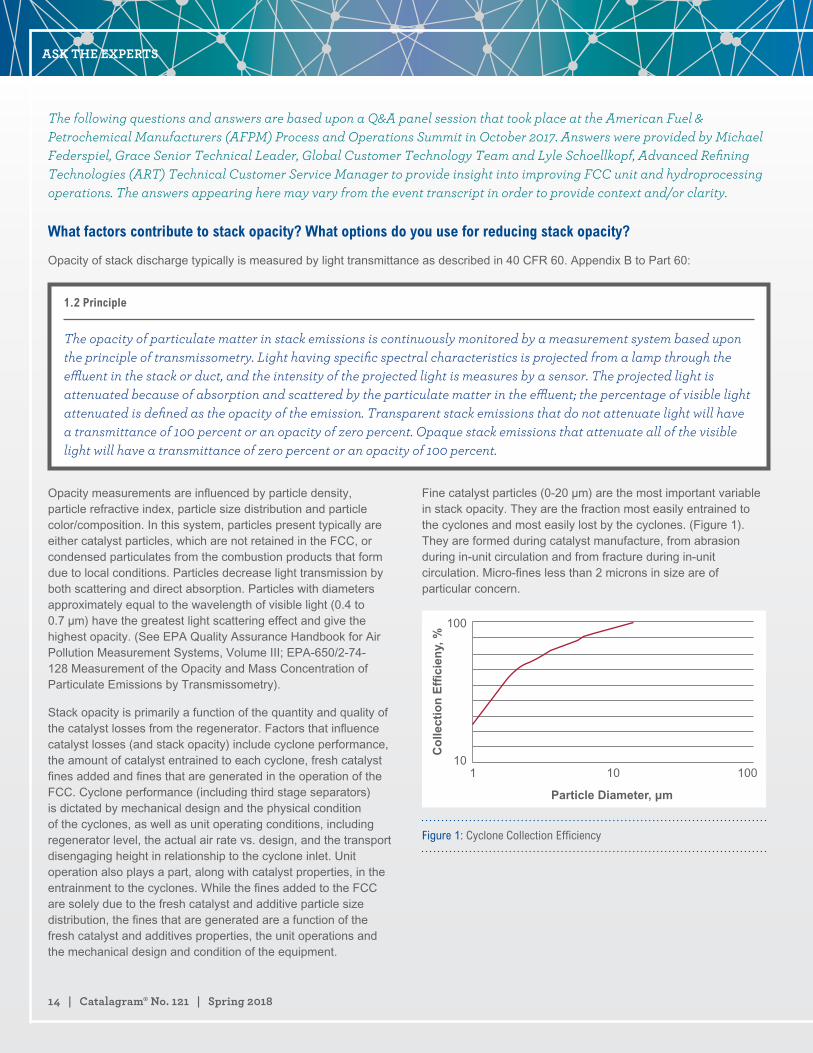
Opacity measurements are influenced by particle density, particle refractive index, particle size distribution and particle color/composition. In this system, particles present typically are either catalyst particles, which are not retained in the FCC, or condensed particulates from the combustion products that form due to local conditions. Particles decrease light transmission by both scattering and direct absorption. Particles with diameters approximately equal to the wavelength of visible light (0.4 to 0.7 µm) have the greatest light scattering effect and give the highest opacity. (See EPA Quality Assurance Handbook for Air Pollution Measurement Systems, Volume III; EPA-650/2-74-128 Measurement of the Opacity and Mass Concentration of Particulate Emissions by Transmissometry).
Stack opacity is primarily a function of the quantity and quality of the catalyst losses from the regenerator. Factors that influence catalyst losses (and stack opacity) include cyclone performance, the amount of catalyst entrained to each cyclone, fresh catalyst fines added and fines that are generated in the operation of the FCC. Cyclone performance (including third stage separators) is dictated by mechanical design and the physical condition of the cyclones, as well as unit operating conditions, including regenerator level, the actual air rate vs. design, and the transport disengaging height in relationship to the cyclone inlet. Unit operation also plays a part, along with catalyst properties, in the entrainment to the cyclones. While the fines added to the FCC are solely due to the fresh catalyst and additive particle size distribution, the fines that are generated are a function of the fresh catalyst and additives properties, the unit operations and the mechanical design and condition of the equipment.
Fine catalyst particles (0-20 µm) are the most important variable in stack opacity. They are the fraction most easily entrained to the cyclones and most easily lost by the cyclones. (Figure 1). They are formed during catalyst manufacture, from abrasion during in-unit circulation and from fracture during in-unit circulation. Micro-fines less than 2 microns in size are of particular concern.
Particle Diameter, μm
Co
llect
ion
Effi
cien
y, %
100
10
Figure 1: Cyclone Collection Efficiency
ASK THE EXPERTS

grace.com | 15
There are several possible sources of attrition through the reactor/regenerator system.
• A hole in the air grid or eroded nozzles
• Excessive dense bed velocity due to high air rate or low pressure
• Excessive cyclone inlet velocity
• High torch oil steam purge rate
• Steam condensate contacting the catalyst
• Tube leak in the catalyst cooler
• Excessive catalyst cooler fluidization medium
• Eroded or missing restriction orifices
• Hole in stripper grid or steam ring
• Hole in dome steam line
• Wet stripping steam
• Open blast points or excessive aeration air or steam to standpipes
• Excessive lift media rates
• High instrument tap purge rate
• Attrition in the catalyst loading lines because of excessive velocity, long distance, or tortuous path
While excessive feed nozzle velocity due to high steam rates or plugged nozzles usually leads to a sharp increase in 1 micron slurry fines, some fines may make their way out of the regenerator and increase opacity.
There are a few methods available to determine the attrition mechanism for a catalyst or additive. Scanning Electron Microscopy (SEM) images of the both the fines and the E-cat show the size and shape of the catalyst particles. The particle size distribution of the fines and E-cat can also provide some insight. (Figure 2).
Figure 2: Particle Size Distribution Of Different Attrition Mechanisms
Comparing the elemental analysis of the fines and E-cat can show whether the fines are concentrated in typical surface contaminants (nickel and iron), indicating abrasion as the attrition mechanism.
Catalyst type also affects attrition and opacity. The catalyst formulation, binder technology and overall catalyst manufacturing process are all important factors in FCC catalyst attrition and stack opacity. Additionally, the morphology of the catalyst particle also plays a role – irregular particles are more likely to undergo attrition than uniform spherical particles. (Figure 3).
97-G (Fresh) 97-R (Fresh)
Figure 3: Morphology of FCC catalyst of the same chemical composition: sample 97-G on the left was twice as attritable as sample 97-R.
By using catalyst and additives with better attrition resistance, stack opacity can be improved, by reducing the generation of fines in the FCC unit. Eliminating attrition sources in the FCC unit, using the list above as a guideline, will also improve stack opacity, especially since the smaller fines generated through catalyst attrition have the greatest impact on opacity. Quickly repairing damage to cyclones and third stage separators will eliminate high losses of larger particles from the FCC. Finally, by operating the FCC within design conditions the risks of mechanical failure in the cyclones and velocity induced attrition are minimized.
ASK THE EXPERTS

16 | Catalagram® No. 121 | Spring 2018
We are reformulating our FCC catalyst. What are the best practices to post-audit the catalyst change?
Preplanning is a very important part of making sure that the catalyst reformulation and post-audit are successful. Before the catalyst trial begins, it is important to define catalyst objectives and establish a clear evaluation plan on how these objectives will be monitored and evaluated for the trial. Sample and data collection guidelines and establishing a good base case should be done before the trial. It is critical that the samples and process data needed to monitor the reformulation are routinely collected before and during the trial. Also, It is suggested to work closely with operations, the refinery lab, and your catalyst supplier to guarantee that samples are being collected and the proper analyses are being performed.
After the process data and samples are collected and analyzed, there are several different methods such as cross-plots, lab testing, and modeling that can be applied to evaluate the benefits of a reformulation.
The first method is the use of cross-plots. Cross-plots are a very useful tool to look at operating data and E-cat data on a similar basis. Figure 1 shows one example of a cross plot where a refinery reformulated the catalyst to improve bottoms upgrading. At similar conversion, the refinery was able to achieve lower bottoms.
Slu
rry,
VO
L%
Conversion, LV%
Catalyst #1 Catalyst #2
Figure 1: Slurry (LV%) vs. Conversion (LV%)
Other cross-plots such as gas factor versus equivalent nickel or gasoline octane versus reactor temperature could be useful to help determine the benefits of a catalyst reformulation. The catalyst objectives will determine which cross-plots are the most meaningful for the trial. When drawing conclusions on cross-plots, different operating conditions, feed quality, and catalyst health should be taken into consideration. This is why laboratory testing and models should be used in conjunction with cross-plots.
Laboratory testing can be used to help evaluate the catalyst reformulation. ACE testing and Grace’s DCR™ (Davison Circulation Riser) testing can be conducted on the equilibrium catalyst to help determine the benefits of the reformulated catalyst. The advantage of lab testing is that it is conducted using fixed operating conditions and a fixed feedstock, which removes the uncertainty in results solely derived from unit operating data due to variability in these parameters over the course of the evaluation. Lab testing should be done with the refinery feed, base equilibrium catalyst and reformulated equilibrium catalyst. If possible, the equilibrium catalyst should be chosen with similar metals levels. This may not be possible during the trial if the unit experiences a shift in metals levels.
Another method to evaluate catalyst reformulation is the use of models. Models are a useful tool to quantify catalyst reformulation benefits since they can be developed to predict yields shifts at defined conditions. When developing, calibrating, and using models, it is important to make sure that data input contain no errors. Before using a model to determine catalyst reformulation benefits, model predicted yields should be compared to actual yields to validate the accuracy of the model. If the model cannot be validated, it should not be used in the evaluation. Two model methods can be used to determine catalyst reformulation benefits. The first method is to calibrate and validate the model for the base catalyst. After the new catalyst is fully turned over, this model can predict what the yields would have been on the base catalyst at similar operating conditions. The predicted yields then are compared to actual yields to determine the benefit of the reformulation. The second method is a double check. The model needs to be calibrated and validated for the reformulated catalyst. This model then can determine what the yields would have been on the new catalyst at base catalyst conditions. These predicted yields can be compared to the actual yields before the trial to determine the benefit. The results from both methods should be compared to make sure that the methods show similar benefits.
In conclusion, evaluating a catalyst reformulation can be very complicated since it is extremely rare for a unit to run in a stable manner with similar operating conditions, similar feed quality, and similar catalyst health. This is why several methods need to be used to quantify the benefits of the catalyst reformulation.
ASK THE EXPERTS

grace.com | 17
With today’s current variety of new crudes, synthetic crudes, tight oils, bio-based streams, opportunity feeds, etc. that find their way to the FCCU; what new metal contaminants (excluding nickel vanadium, iron, and sodium) impact catalyst and FCC performance?
In addition to the “standard” contaminants of nickel, vanadium, iron and sodium, there are a variety of other feed contaminants that can impact FCC performance. For example, tight oils (also known as shale oils) can contain high levels of potassium, magnesium, and calcium in addition to the iron normally found in them1. While bio-based feedstocks are not yet widely processed in commercial units, they would be expected to contain higher levels of calcium, sodium, magnesium and potassium than conventional feed sources since these elements all play an important role in biological systems. High levels of phosphorous have been found on synthetic crudes. Opportunity crudes can contain a variety of non-standard metals, including copper, zinc, silicon, mercury and arsenic. Molybdenum and cobalt can also find their way into FCC feedstock. At times, it seems like every element in the periodic table can wind up in the FCC.
These metals can be considered in three groups:
1. alkali and earth alkaline metals
2. other metals
3. other contaminants.
For many elements, histograms of contaminant levels on E-cat are presented. These histograms are based on a worldwide survey of more than 270 FCC units and the data is a one year average for each unit of the E-cat samples tested.
Alkali and Earth Alkaline MetalsSimilar to sodium, the alkali metal potassium will reduce activity by poisoning active sites and will also result in zeolite destruction. Alkaline metals in feed, such as calcium, magnesium and barium, will result in zeolite degradation, similar to that seen with sodium. Classic work by Letzsch and Wallace2. found that on an added weight percent basis, potassium is ~0.5-1x as destructive as sodium, and that calcium and magnesium are less destructive than sodium. Barium was found to be less destructive than the other alkaline earth metals. Calcium in combination with iron can be especially detrimental. As described in the answer to Question 44 at the 2009 NPRA Q&A, calcium along with other elements such as iron and sodium, can act as a fluxing agent to form low melting point phases on the surface of the catalyst. This results in the collapse of the pore structure on the surface of the catalyst particle, and a reduction in conversion since it is harder for feed molecules to enter the catalyst particle. As seen in Figure 1, levels of potassium on equilibrium catalyst are generally low, with the worldwide average at 0.05 wt.%. This contrasts with sodium,
where the average level on E-cat is 0.26 wt.%. Most magnesium in equilibrium catalyst comes from SOx reduction additives or metals trapping components instead of feed. Figure 2 presents a histogram of magnesium oxide concentration in E-cat for units worldwide. Calcium can come from feed, although there are a few units that use calcium containing additives. As seen in Figure 3, more than 90% of the world’s FCC units run at calcium levels below 0.5 wt.% on E-cat. As seen in Figure 4, barium levels are generally low, with 95% of the world’s FCC units at barium levels below 0.1 wt.% on E-cat.
Nu
mb
er o
f U
nit
s
Potassium, wt.%
Figure 1: Average concentrations of potassium on E-cat for FCC units worldwide.
Nu
mb
er o
f U
nit
s
MgO, ppm
Figure 2: Average magnesium oxide concentrations on E-cat for FCC units worldwide.
Continued on Page 18
ASK THE EXPERTS

18 | Catalagram® No. 121 | Spring 2018
Nu
mb
er o
f U
nit
s
Barium, wt.%
Figure 4: Average concentrations of barium on E-cat for FCC units worldwide.
Nu
mb
er o
f U
nit
s
Calcium, wt.%
Figure 3: Average calcium concentrations on E-cat for FCC units worldwide.
Other MetalsMany metals such as molybdenum, cobalt, copper and zinc, act as dehydrogenation catalysts, similar to nickel and vanadium.
Molybdenum is a rare feed contaminant, but can result in zeolite destruction and an increase in coke and hydrogen. It can be present in feed either from the starting crude oil or from carryover of hydroprocessing catalyst. While cases of molybdenum poisoning are rare, it can have a very detrimental effect. In one refinery, a severe increase in molybdenum, by 1700 ppmw, resulted in a six number drop in E-cat MAT, a tripling of the E-cat gas factor, and a more than 50% increase in the E-cat coke factor. In another refinery, an increase in molybdenum from 40 ppmw to 180 ppmw resulted in doubling of hydrogen production in E-cat testing. While the detrimental effects of molybdenum will vary with regenerator conditions (full burn vs. partial burn and temperature), as a rough approximation, molybdenum appears at least five times as active as vanadium on a weight basis. Fortunately, molybdenum is a rare contaminant in most units. As seen in Figure 5, with the exception of one unit, molybdenum levels on E-cat are below 100 ppmw.
While cobalt is not typically found in the feed unless it comes in from hydrotreaters ahead of the FCCU, it can result in increased hydrogen and coke. As seen in Figure 6, cobalt levels are generally low, with 90% of the world’s FCC units at cobalt levels below 200 ppmw.
Nu
mb
er o
f U
nit
s
Molybdenum, ppm
Figure 5: Average concentrations of molybdenum on E-cat for FCC units worldwide.
Nu
mb
er o
f U
nit
s
Colbalt, ppm
Figure 6: Average concentrations of cobalt on E-cat for FCC units worldwide.
Continued from Page 17
ASK THE EXPERTS

grace.com | 19
Nu
mb
er o
f U
nit
s
Zinc, ppm
Figure 8: Average concentration of zinc on E-cat for FCC units worldwide, with known zinc based GSR® additives users excluded.
Nu
mb
er o
f U
nit
s
Copper, ppm
Figure 7: Average concentrations of copper on E-cat for FCC units worldwide.
The dehydrogenation activity of copper is typically about the same as that of nickel on a weight basis3. The copper content of most FCCU feeds is very low so it is normally not a problem. As seen in Figure 7, copper levels are generally low, with 95% of the world’s FCC units at copper levels below 100 ppmw.
Zinc from feed is another metal with dehydrogenation activity. In a 1996 NPRA Q&A, one respondent to question #18 on processing used lube oils stated that they found that zinc tended to have lower dehydrogenation activity than nickel. We have observed several North American units experience spikes of zinc on E-cat of 1000 to 2000 ppmw in the last two years, possibly from zinc additives in their crude slate. In addition to coming from feed, zinc is used in some gasoline sulfur reduction additives and zinc from this source will appear on E-cat reports. Zinc in gasoline sulfur reduction additives does not have the dehydrogenation activity of zinc introduced from feedstock. Figure 8 presents average zinc levels on E-cat world-wide, with known zinc-based GSR® additive users removed. As seen in Figure 8, 90% of FCC units have less than 500 ppmw zinc on E-cat.
Lead can come from the source crude oil or very rarely from recycled aviation gasoline slop streams fed to the FCC. Lead is well known to cause the deactivation of combustion promoter, resulting in detrimental effects at levels of even 100ppmw4. Work in 1987 established that in large enough concentrations on E-cat, lead can also cause a loss in catalyst activity and conversion. In that work, 800ppmw lead resulted in a loss of 2-4 numbers of MAT activity5. Experience with equilibrium catalyst suggested that 1000 ppmw lead would result in a loss of 1% conversion6. However, there are almost no units operating at these levels of lead in the industry today, 95% of units are below 300 ppmw lead on E-cat and 85% of units are below 100ppmw lead on E-cat. Figure 9 presents industry average data for lead on E-cat.
Continued on Page 20
Nu
mb
er o
f U
nit
s
Lead, ppm
Figure 9: Average concentrations of lead on E-cat for FCC units worldwide.
ASK THE EXPERTS

20 | Catalagram® No. 121 | Spring 2018
Other ElementsHigh levels of phosphorous can be found in shale oils and in Western Canadian crudes. The phosphorous appears to come from fracking fluids and gelling agents used in well stimulation. In our experience, we have seen P2O5 on E-cat increase by up to 0.1 wt.% with a change in FCC feedstock slate. The levels are not high enough to affect FCC catalyst, but the phosphorous is often a problem in the main fractionation tower and the hydrotreater. The 2013 AFPM Q&A questions 31, 36, and 65 address the effects of phosphorous in units other than the FCC.
Silicon can come from crude oil or from antifoaming agents. Since silicon oxide is present in the composition of the base catalyst, we would not expect silicon from feed to have an effect on FCC catalyst and have not observed any effects. However, silicon is a significant poison for hydroprocessing catalysts and this topic has been discussed in earlier AFPM Q&As7.
Mercury can be found in trace levels in many hydrocarbons. Under FCC conditions, mercury is very volatile and would not be expected to build up on FCC catalyst. While mercury would not affect FCC catalyst, it can concentrate in cooler downstream units. For example, there is a reported case of pooled mercury being found in an FCC flue gas line during a unit shutdown8. Arsenic is naturally found in crude oil. The arsenic compounds in FCC feedstock primarily react to arsine (AsH3) and additionally some arsenic leaves the unit in the liquid products. Arsenic is highly reactive towards nickel and noble metals and arsenic compounds have a negative effect on the catalysts of downstream units for reactions such as polymerization, reforming, and hydrotreating9. Guard beds are often used to remove the arsenic containing compounds and protect catalyst
in downstream units. Arsenic in FCC feedstock has not been found to deactivate the cracking catalyst. This is likely since arsenic is not reactive towards the silica-alumina structure of the zeolite. Levels Grace has seen for arsenic on E-cat are typically below 20 ppmw. An important consideration in measuring arsenic in E-cat and fines is the analysis method. Inductively coupled plasma atomic emission spectroscopy (ICP-AES) is not suitable for determining arsenic levels in E-cat since the lanthanum in the E-cat will interfere with the arsenic line such that incorrect high levels of arsenic will be reported. Difficulties with ICP-AES analysis for samples with both arsenic and lanthanum have been observed in other industries10. Preferred techniques for determining arsenic on E-cat and fines are Inductively coupled plasma mass spectroscopy (ICP-MS) and Neutron activation analysis (NAA). Potential interferences exist in these two methods also and any lab doing analysis should be informed of the presence of lanthanum.
References1. K. Bryden, M. Federspiel, E.T. Habib and R. Schiller, AM14-16, Processing
Tight Oils in FCC: Issues, Opportunities and Flexible Catalytic Solutions.
2. W.S. Letzsch and D.N. Wallace, “The Effect of Alkali and Alkaline Earths on
Zeolitic Fluid Cracking Catalysts,” Catalagram #65, 1982.
3. Questions Frequently Asked about Fluid Cracking Catalysts, Catalagram #64,
1982.
4. Question #36, 1984 NPRA Q&A.
5. Questions Frequently Asked, Catalagram #76, 1987.
6. Question #44, 2009 AFPM Q&A.
7. Question #46, 2014 AFPM Q&A.
8. Question #99, 2011 NPRA Q&A and Technology Forum.
9. Siegel, J. and Olsen, C., “Feed Contaminants in Hydroprocessing Units,” ART
Catalagram 104, Fall 2008.
10. Gunderson, K, “Problems with Arsenic Detection: When NIOSH and EPA
Methods Fail,” American Industrial Hygiene Conference and Exposition,
Chicago, May 17, 2006.
Continued from Page 19
ASK THE EXPERTS
grace.com | 21
When performing catalyst evaluations and considering catalyst resistance to attrition with regard to particulate matter (PM) emission requirements; what new or Advanced attrition testing methods are used to predict the performance of the new catalyst system? Are there third parties who can conduct a standard testing regime to multiple catalyst systems?
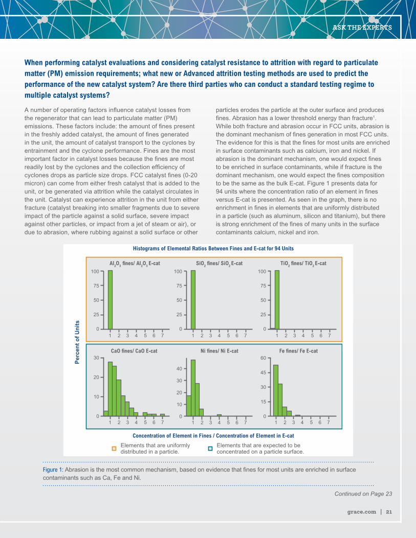
A number of operating factors influence catalyst losses from the regenerator that can lead to particulate matter (PM) emissions. These factors include: the amount of fines present in the freshly added catalyst, the amount of fines generated in the unit, the amount of catalyst transport to the cyclones by entrainment and the cyclone performance. Fines are the most important factor in catalyst losses because the fines are most readily lost by the cyclones and the collection efficiency of cyclones drops as particle size drops. FCC catalyst fines (0-20 micron) can come from either fresh catalyst that is added to the unit, or be generated via attrition while the catalyst circulates in the unit. Catalyst can experience attrition in the unit from either fracture (catalyst breaking into smaller fragments due to severe impact of the particle against a solid surface, severe impact against other particles, or impact from a jet of steam or air), or due to abrasion, where rubbing against a solid surface or other
particles erodes the particle at the outer surface and produces fines. Abrasion has a lower threshold energy than fracture1. While both fracture and abrasion occur in FCC units, abrasion is the dominant mechanism of fines generation in most FCC units. The evidence for this is that the fines for most units are enriched in surface contaminants such as calcium, iron and nickel. If abrasion is the dominant mechanism, one would expect fines to be enriched in surface contaminants, while if fracture is the dominant mechanism, one would expect the fines composition to be the same as the bulk E-cat. Figure 1 presents data for 94 units where the concentration ratio of an element in fines versus E-cat is presented. As seen in the graph, there is no enrichment in fines in elements that are uniformly distributed in a particle (such as aluminum, silicon and titanium), but there is strong enrichment of the fines of many units in the surface contaminants calcium, nickel and iron.
Continued on Page 23
Histograms of Elemental Ratios Between Fines and E-cat for 94 Units
Concentration of Element in Fines / Concentration of Element in E-cat
Al2O3 fines/ Al2O3 E-cat SiO2 fines/ SiO2 E-cat TiO2 fines/ TiO2 E-cat
Fe fines/ Fe E-catCaO fines/ CaO E-cat Ni fines/ Ni E-cat
Per
cen
t o
f U
nit
s
Elements that are expected to be concentrated on a particle surface.
Elements that are uniformlydistributed in a particle.
Figure 1: Abrasion is the most common mechanism, based on evidence that fines for most units are enriched in surface contaminants such as Ca, Fe and Ni.
ASK THE EXPERTS

Let’s do the math.Grace custom catalyst solutions, co-developed with you, are about more than performance—and more than chemistry. They’re designed to add to your bottom line.
In some cases, the difference between our refinery customers’ financial return on Grace technologies versus the alternative has reached into eight figures.
If you’re ready to put Grace chemistry to work to strengthen your business, we’re ready to show you how we can help. Call us to get started with the calculations.
grace.com
Tested. Proven. Valued.
At Grace, value is all about our customers’ financial success.
Learn more at grace.com/value.

grace.com | 23
There are a variety of lab methods that have been used to simulate in the lab the particle attrition that occurs in a commercial unit. They all involve subjecting catalyst to more severe attrition than is experienced in a commercial unit. One sophisticated method involves passing the catalyst through a series of cyclones at high velocity2. These cyclone tests provide insight into attrition fundamentals, but the large amount of sample required and the long testing times prevent their use for routine testing of catalysts for attrition. The most common test methods for routine catalyst testing are methods based on the air jet and the jet cup. In both methods, the catalyst is subjected to a high velocity air stream resulting in fines generation. The amount of fines generated is a measure of the attrition resistance of the catalyst. In the air jet method, most of the collisions are particle/particle, while in the jet cup method, both particle/particle and particle/wall collisions occur. Examples of attrition testing equipment based on the air jet method are ASTM D57573, and the designs of Forsythe and Hertwig4 and Gwyn5. Examples of attrition testing apparatus based on the jet cup method include the Davison Index (DI)6,7, and jet cup equipment developed by PSRI8 and other labs9. There are several jet cup designs reported in the literature. It is important to note that the dimensions, volume and configuration of the jet cup all play a role in its performance and that some jet cups described as “Davison-type” jet cups are not the same as the jet cup used in the Davison Index test method practiced by Grace.
We are often asked how jet cup methods compare to the ASTM D5757 air jet method. Attrition resistance measured by ASTM D5757 (an air jet method) and by Grace's DI test (a jet cup method) give comparable results in that lower values on each scale are more attrition resistant. It is not possible to directly correlate the scales of the two tests since they are different apparatus, but they tend to give values of the same order of magnitude. In round robin testing with an external lab, Grace found that that two methods gave the same ranking regarding catalyst attrition10. Similarly, a recent paper by Kukade, et. al.11, found that the performance ranking of catalysts did not vary between ASTM D5757, a cylindrical jet cup and a conical jet cup. While the methods give similar rankings, it is important to remember that their scales differ, so testing with the same method is necessary for an “apples-to-apples” comparison between catalysts.
For third party testing of catalyst systems, two organizations that we are aware of that conduct this testing are CPERI (Chemical Process & Energy Resources Institute) and PSRI (Particulate Solid Research Inc.)
References1. J. Werther and J. Reppenhagen, “Attrition,” in Handbook of Fluidization and
Fluid Particle Systems, W.-C. Yang, editor, Marcel Dekker, 2003.
2. J. Reppenhagen and J. Werther, “Catalyst Attrition in Cyclones,” Powder
Technology 113 (2000) 55-69.
3. ASTM D5757 ”Standard Test Method for Determination of Attrition and
Abrasion of Powdered Catalysts by Air Jets.”
4. W.L. Forsythe and W.R. Hertwig, “Attrition characteristics of fluid cracking
catalysts,” Ind Eng. Chem 41:1200–1206, 1949.
5. J.E. Gwyn, “On the particle size distribution function and the attrition of
cracking catalysts,” AIChE J 15:35–38, 1969.
6. S. A. Weeks and P. Dumbill, “Method speeds FCC catalyst attrition resistance
determinations,” Oil Gas J 88:38–40, 1990.
7. Work Item WK34893 under discussion by ASTM D32 Committee- “Standard
Test Method for Measurement of Jet Cup Attrition Index of Fluid Catalytic
Cracking Catalyst and Catalyst Additives”
8. R. Cocco, Y. Arrington, R. Hays, J. Findlay, S.B.R. Karri, T.M. Knowlton, “Jet
Cup Attrition Testing,” Powder Technology 200 (2010) 224-233.
9. J. Hao, Y. Zhao, M. Ye, Z. Liu, “Attrition of methanol to olefins catalyst in jet
cup,” Powder Technology, 316 (2017) 79-86.
10. G.P. Singaravel, K. Schäfer, S. Brandt and C.M. Fougret, “New Aspects in
the Determination of Physical Properties of FCC Catalysts,” 7th TRC-JCCP/
Idemitsu Refining R&D International Symposium “Research & Development
for a Sustainable Refining Industry” 25th - 27th September 2017, Abu Dhabi,
UAE.
11. S. Kukade, P. Kumar, P.V.C. Rao, N.V. Choudary, “Comparative study of
attrition measurements of commercial FCC catalysts by ASTM fluidized bed
and jet cup test methods,” Powder Technology 301 (2016) 472-477.
Continued from Page 21
ASK THE EXPERTS

24 | Catalagram® No. 121 | Spring 2018
Do you know of factors that are likely to lead to deposit formation on power recovery turbine blades? Is there anything that can be done to avoid these deposits from laying down on the blades? Once the deposits have been formed, what are the consequences and is there any way to remove the deposits online?
The paper “Catalyst Deposition in FCCU Power Recovery Systems” by David H. Linden at Ingersoll-Rand, refers to four 4 types of deposits that occur in flue gas lines, equipment and power recovery turbines. The first type (A) are powdery catalyst deposits that cling to surfaces in the flue gas train. The second type (B) occurs when those powdery catalyst deposits get wet and then harden after drying out. Upon analysis, these deposits appear similar in chemical makeup to equilibrium catalyst or third stage separator fines.
The third type (C) of deposit is made up of very small catalyst particles, along with elevated levels of alkali metals (sodium, potassium, calcium) chlorides, vanadium and iron, and other trace contaminants from unique or challenging feedstocks. It is theorized that these contaminants form a low melting point eutectic. These deposits are very hard and are often found in areas of high gas velocity and pressure drop, and the expander is just such a place. If these deposits form along the expander blade tips to sufficient thickness to cause rubbing, the friction can increase the temperature enough to sinter the deposit into a new type (D) of deposit with increased metals content from the expander metallurgy.
By reducing catalyst traffic to the flue gas and preventing condensation, these types of deposits can be minimized. Keeping the regenerator cyclones and third stage separator mechanically healthy and operating within design specifications will help. Ensuring catalyst coolers are leak free will prevent boiler feed water chemicals from further contaminating catalyst and eliminate an attrition source. Running the expander at
design conditions can keep the flow path through the expander fully developed, minimizing eddy currents and dead spaces. Minimizing the contaminant metals (particularly those that accumulate on the surface of the catalyst particle and then abrade off), or using a catalyst with a low attrition tendency can help to minimize deposits. There are also several options for expander coatings, which reduce or prevent the accumulation of deposits.
Monitoring deposits during the run can help a refiner be prepared for work that needs to be done during the next available outage.Pictures taken through view ports and vibration monitoring are two common methods used to quantify and track deposit formation.
Once formed, deposits can cause loss of expander efficiency and threaten the mechanical integrity of the machine as well as force a shutdown due to high vibrations. While these deposits can be removed through the injection of walnut shells or rice, a regular program aimed at preventing the formation of deposits is generally more effective at achieving longer run lengths than attempting to fix a vibration issue after it develops. Varying the size of the media can help reach the different places these deposits form. Other methods include thermal shocking or thermal cycling of the expander, which takes advantage of the different thermal expansion coefficients of the deposits and the turbine metallurgy to release accumulated deposits from the surface of the blades.
References1. “Catalyst Deposition in FCCU Power Recovery Systems” by David H. Linden,
Ingersoll-Rand
ASK THE EXPERTS

grace.com | 25
What strategies do you employ to optimize FCC plus hydrocracker operations? Do you process hydrocracker-unconverted oil (UCO) in the FCC, or FCC LCO/HCO in the hydrocracker?
The ability to optimize FCC and hydrocracker (HCR) operations will depend on many refinery specific factors. The first of these factors is the specific operating modes of the FCC and the hydrocracker. We can generically group FCC operations as “Gasoil (FCC)” and “Resid (RFCC)”, and generically group hydrocrackers as “Full conversion (FCHR)” and “Partial Conversion (PHCR)”. An additional configuration factor which will impact the optimization solution is the existence of a cat feed hydrotreater (CFH) or resid hydrotreater (RDS).
In the simplest optimization, considering FHCR and FCC/RFCC, it's almost always beneficial for both conversion units to divert some hydrocracker unconverted oil to the FCC. Converting that last barrel of feed in the HCR can often result in higher gas make and lower total liquid than if the same barrel were cracked in the FCC. However, depending on the amount and quality, UCO can cause fouling in the FCC slurry circuit, so this must be considered.
Synergistic benefits are highly refinery specific, and are impacted by availability and type of feed to both units, prices of feedstock and products (including hydrogen), and refinery operational objectives. Often the operational objectives can have the largest impact. Typically, cost of catalysts are not a big factor in this exercise. A detailed study, led by or including FCC and HCR SME’s, as well as the refinery planning group is recommended to ensure success. One of the most important steps is to determine the expected
longevity and variation in those factors, which drive the synergy, so the team can determine if a more complex FCC and hydrocracker integration project can be expected to provide benefits.
Some PHCR's are designed for synergy with the FCC. In these cases, modern hydrocracking catalyst developments can offer unexplored/unexpected synergies. Adding capacity to the FCC/RFCC, improving the mechanical condition (upgrade or turnaround) of the FCC/RCC, or addition of CFH or RDS may allow for further optimization steps, including converting the PHCR to higher conversion or partial recycle operation to increase desired products in both conversion units and/or reduce hydrogen consumption.
When feed streams are discrete, one optimization that can be counterintuitive is to not necessarily process the most difficult feedstocks in the high pressure HCR's; the most economic place for these streams may be in the CFH or RDS. The HCR severity increase with challenging feed streams, such as HCGO or DAO, can have a very negative effect on both the product slate as well as product qualities. This can overwhelm any benefit from improved FCC operation. Of course, we are not suggesting that HCR's be fed highly convertible HGO or LVGO only. But, there will be a happy optimum that technology SMEs' can help each refinery find.
Finally, on the question of LCO and HCO processing in the hydrocracker, answers are again complex. HCO
processing is not recommended in the HCR as HCO contains very stable multi-ring hydrocarbons that will pass through the HCR unconverted (at best) or precipitate out onto catalysts causing deactivation. Even if the HCR is able to crack the HCO using specialized catalysts (such as self-supported catalysts like ICR 1001 from ART), hydrogen consumption would be very high, and could reduce economic benefit. Often, a leading home for the HCO is in the refinery fuel oil pool.
LCO processing in a hydrocracker could also be a counterintuitive case. Normally if the HCR's were designed to process LCO, then there are no issues. Depending on availability and cost of hydrogen, processing LCO can lead to high volume gain and good economics. However, there are cases where LCO is added intermittently to increase bed temperature rise and to kick off the reaction in downstream beds. But the effectiveness of this strategy is highly dependent on the feedstock and catalysts used in the downstream beds. LCO's contain very reactive molecules that will preferentially occupy hydrogenation sites of catalysts in the top half of the hydrocracking reactor. Therefore, depending upon catalyst type and placement, overall yield response may not meet expectations. Careful consideration and a study with HCR SME's is recommended to ensure that such synergy actually exists.
The lesson is to continuously study to identify synergistic opportunities with HCR and FCC SME's.
ASK THE EXPERTS

26 | Catalagram® No. 121 | Spring 2018
What process and catalyst changes would you recommend for a refinery that is planning on processing a percentage of resid in an FCCU that typically runs gas oil?
One specific challenge related to catalyst in processing resid is achieving a proper balance of metals tolerance, catalyst activity, and bottoms upgrading. Recommendations on catalyst changes will be dependent on the quality and variability of the resid. It is critical to understand these parameters.
For example, when processing resid, refiners experience an increase in metals contamination on the circulating equilibrium FCC catalyst. The crude slate will determine the type of metals that will be present in the resid being processed in the FCC. Understanding the metals profile, which includes both the expected concentration and variability in concentration of contaminants, is critical in a catalyst selection strategy. Different strategies are implemented for varying types of metals. Catalyst strategies such as catalyst reformulation, increased catalyst additions, and introduction of a flushing purchased equilibrium catalyst are all options that should be considered when dealing with significantly increased metals contamination. One of the contaminant metals that needs to be addressed is nickel (Ni). Higher levels of Ni on equilibrium catalyst cause incremental coke and dry gas, principally as increased hydrogen. Addressing the increase in Ni is particularly important if the unit is expected to experience or is currently experiencing wet gas compressor limitations. The negative impacts of Ni can be offset by catalyst reformulation, antimony injection, or a combination of both. Catalyst can be formulated to incorporate nickel trapping components. Grace utilizes a matrix alumina to trap nickel to reduce the harmful effects. In this system, nickel that deposits on the catalyst undergoes a solid-state chemical reaction that diminishes nickel’s dehydrogenation activity (1). Figure 1 shows how a refinery utilized a nickel trap to help reduce the harmful impacts of the metal. The refinery was able to achieve similar dry gas despite the increase in nickel.
Antimony injection (Sb) can also be utilized to offset the harmful effects of Ni. Industry data suggests that typical refiners start to use Sb at nickel levels of 1000 ppm (Figure 2).
Vanadium can also become an issue when processing resid; it destroys zeolite and increases production of coke and dry gas. Vanadium takes the form of vanadic acid, which is volatile in the regenerator and as a result, it is mobile. Vanadic acid is a strong acid that destroys zeolite by hydrolysis of its silica/alumina framework. Vanadium also acts as a dehydrogenation catalyst, however, the dehydrogenation activity of vanadium is roughly one fourth that of nickel. It is advantageous to trap the vanadium into an inert form. Grace uses an integral rare earth trap technology, which has proven to be very effective for controlling vanadium poisoning. The rare earths are “basic” oxides and can react with vanadic acid, trapping it and preventing reaction with the zeolite to reduce the harmful impact of the metal.
Iron (Fe) and Calcium (Ca) are other metals that can pose potential complications when processing a percentage of resid. To address iron (Fe) and calcium (Ca) problems, it is crucial to have an FCC catalyst that is designed to resist negative impacts of the metals. High alumina catalysts, especially catalysts with alumina-based binders and matrices, are best suited to process iron- and calcium-containing feeds because they are more resistant to the formation of the low melting-point phases that destroy the surface pore structure. To avoid experiencing negative impacts due to these metals, refiners should evaluate switching to a more iron/calcium resistant catalyst, and may also consider higher catalyst addition rates to flush the metals from the system.
ASK THE EXPERTS
Catalyst 2 (Nickel Trap)
Catalyst 1
Gas
Fac
tor
Nickel Equivalent
Figure 1: Gas Factor vs. Nickel Equivalent
Sb
, pp
m
Ni, ppm
Industry E-cat Data
Figure 2: Industry E-cat Data: Sb (ppm) vs. Ni (ppm)

grace.com | 27
One catalyst strategy that can be implemented in conjunction with catalyst reformulation is the use of purchased E-cat as a flushing media. Purchased E-cat will need to be evaluated to ensure that it is the proper quality for a resid application. If available, a purchased E-cat with low metal content and the proper zeolite-to-matrix should be selected as a flushing catalyst. It can be challenging to identify a suitable E-cat, since many E-cats available for purchase are from VGO units whose catalysts are not designed to handle resid feedstock.
To prepare for the increased metals loading and the anticipated increase in total catalyst additions, it is important to assess the capability of your catalyst transfer and loading systems to handle the higher rates of solids.
Another specific challenge is targeting the proper catalyst activity for the new mode of operations. Regenerator temperature typically increases when processing a percentage of resid. To stay within regenerator temperature limitations, fresh catalyst activity will need to be reduced to allow for increased catalyst additions to purge contaminate metals.
Another change that will need to be considered is the proper catalyst design. The catalyst needs to be formulated to improve bottoms cracking while maintaining superior coke selectivity, which will help offset the higher bottoms yield. Optimum pore volume, pore size distribution, and zeolite-to-matrix ratio are crucial to optimizing bottoms cracking and coke selectivity. It is recommended to discuss with your catalyst supplier to make sure you are getting the optimum catalyst for the new mode of operation.
In addition to catalyst changes, operational changes will also need to be considered when processing resid. Regenerator temperature may become an issue and can be addressed by reducing riser temperature, reducing feed rate, or if available, by adjusting catalyst cooler duty.
Decreasing feed preheat is another option that can be considered, but feed nozzle operations should be monitored when making adjustments to preheat. The minimum feed temperature while processing resid could be different than processing vacuum gas oil. Understanding this minimum feed temperature is important to ensure proper feed atomization. There can be a point where regenerator temperature increases instead of decreases when feed preheat is decreased. If this occurs, it would indicate that the feed atomization is not adequate at the set feed temperature. This is illustrated in Figure 3.
Reg
ener
ato
r B
ed T
emp
erat
ure
Feed Temperature
Lower temperaturereduces nozzle effectiveness
Figure 3
In conclusion, it is critical to understand the quality, consistency, and quantity of the resid that will be processed in the unit. This understanding is needed to create a well thought out catalyst and operating strategy for successfully processing resid in the unit.
References1. Thomas F Petti, Douglas Tomczak, Carmo J Pereira, Wu-Cheng Cheng,
“Investigation of nickel species on commercial FCC equilibrium catalysts-
implications on catalyst performance and laboratory evaluation,” Applied
Catalysis A: General, Volume 169, Issue 1, 17 April 1998
ASK THE EXPERTS

28 | Catalagram® No. 121 | Spring 2018
What operational or other changes prompt evaluation and optimization of standpipe aeration? What do you monitored to ensure the standpipes remain fluidized across a range of conditions?
Standpipe aeration is provided to replace the volume of gas lost in a fluidized catalyst as head pressure builds and compresses the gas. Not all standpipes have provisions for aeration; usually those without aeration taps are short in length and have minimal change in direction. Longer standpipes require aeration to ensure the smooth circulation of catalyst and sufficient slide valve delta P.
To calculate how much aeration a given standpipe requires, the first step is to calculate the volume of circulating catalyst emulsion (V
Emulsion).
V"#$%&'() = Q-./.%0&/ρ"#$%&'()
V
Emulsion is used to calculate the volume of gas circulated with
the catalyst.
V"#$ = V&'()$*+, ×1 − ρ&'()$*+,SkeletalDensity
The next step is to calculate the absolute pressure at the inlet to the standpipe and at each aeration tap location. P"#$%& = P()$*&% +P-.*$/)0# × ∆H , where ΔH is the distance from the inlet to the top of the bed, and
P"#$ = P&'()* + P-./(012' × ∆H , where ΔH is the distance from the tap to the inlet.
Finally, the calculated terms VGas
, PInlet
, and PTap
are used to calculate the change in gas volume due to the increased pressure.
∆𝑉𝑉#$% =V#$% − (𝑉𝑉*+, × 𝑃𝑃/0123)
𝑃𝑃5+6
ΔVGas
is the theoretical amount of aeration required at each tap.
Note: each tap must be calculated individually and experience shows the actual aeration requirement is usually 30% lower than theoretical.
Large changes in catalyst circulation rate, bed density (Emulsion Density or ρ in the calculation above), or system pressure should trigger an optimization of standpipe aeration. Additionally, if any taps along the standpipe were to become plugged with catalyst, the surrounding taps would need an adjustment.
Although the skeletal density of different FCC catalysts are usually very similar, changes in catalyst can impact the emulsion density and pressure profile, requiring aeration optimization. Catalyst properties (along with aeration medium) also sets the Maximum Stable Expansion Ratio (MSER), which is defined as:
MSER =CatalystDensityatIncipientFluidization
CatalystDensityatIncipientBubbling
The MSER indicates the “width of the operating window” over which a bed of fluidized catalyst is well behaved. In the context of a standpipe, the MSER indicates how much a fluidized bed can be compressed before it reverts to a packed bed (defluidizes). The MSER is a function of catalyst particle density (with ABD used as a proxy) and 0-40 fines content, as shown in Figure 1.
0-40 Fraction, wt.%
0.83 ABD
0.92 ABD
0.81 ABD
0.85 ABD
0.87 ABD
MSER (Density IF / Density IB)
Figure 1: Maximum Stable Expansion Ratio at Different Catalyst Properties
Monitoring the physical properties of the FCC catalyst is an important part of standpipe aeration optimization. Changing catalyst types should cue an evaluation of the standpipe aeration.
ASK THE EXPERTS

grace.com | 29
Taking a single gauge pressure survey of the standpipe can give valuable insight into the condition of the standpipe’s aeration. This is especially important to do while the unit circulation is healthy in order to establish a baseline, as shown in Figure 2. Pressure profiles like those in Figure 3 indicate it’s time to adjust standpipe aeration.
Finally, monitoring slide valve delta P is another method of tracking standpipe aeration. If the slide valve delta P unexpectedly changes or becomes erratic, the standpipe aeration should be reviewed.
Finally, monitoring slide valve delta P is another method of tracking standpipe aeration. If the slide valve delta P unexpectedly changes or becomes erratic, the standpipe aeration should be reviewed.
Elev
atio
n
Pressure
Standpipe withCirculation Problems
Elev
atio
n
Pressure
Severe Circulation Problems
Figure 3: Abnormal Standpipe Pressure Profiles
Elev
atio
n
Pressure
Normal Operation
The line slope is the SP Density:
RCSP Density ~35 lb/ft3
SCSP Density ~38 lb/ft3
Figure 2: Typical Standpipe Pressure Profile
Electrostatic Precipitator (ESP) fines handling is often complicated by fluidization and mechanical integrity issues. How often do refiners experience these types of fines handling issues and what are some of the best practices to successfully mitigate these issues? What are best practices for safe fines withdrawal from the ESP?
Electrostatic Precipitators (ESPs) represent an effective medium for particulate emissions control and are, therefore, commonly used within the FCC industry – especially in North America. Although ESPs are not designed to capture all of the catalyst particles present in the regenerator flue gas, they usually exhibit sufficient performance to successfully reduce the particulate content in the flue gas below 50 mg/Nm3. As the question suggests, fluidization and mechanical integrity issues can significantly hinder the catalyst fines withdrawal and handling activities. With respect to mechanical integrity, the most common issues correspond to malfunctioning catalyst discharge valves to the collection hoppers due to any of the following causes, among others:
• Internal abrasion throughout long-term operation
• Misalignment of the valve fittings due to thermal cycling
• Fouling seats or guides due to catalyst particle deposits
The electrode and collection plate rappers can also experience mechanical integrity issues that can significantly hinder catalyst withdrawal efficiency. These mechanical rappers help maximize the recovery of the ESP fines while properly preserving electrode efficiency and performance throughout long-term operation. Complete failure or suppressed performance of these rappers generally reduces the amount of fines withdrawn from the system at constant particulate loadings, and can significantly shift the particle size distribution (PSD) of the withdrawn fines towards a coarser profile. The reduced fines withdrawal capabilities are usually accompanied by gradual increases in particulate emissions at the stack beyond the normal, or allowable, ranges. The mechanical integrity of the rappers can be affected by thermal cycling over time as well as fouling issues stemming from the ingress of fines.
Continued on Page 30
ASK THE EXPERTS

30 | Catalagram® No. 121 | Spring 2018
Operating conditions also influence the mechanical integrity of the ESP. Sudden thermal cycles, such as those associated with an emergency trip of the unit or sudden bypass of the ESP train, can increase the threat of mechanical integrity deficiencies associated with buckling or thermal expansion. Electrical or pneumatic supply deficiencies have also been reported, although they can be mitigated through redundant supply systems and/or onsite spare parts for the critical components. These types of mechanical failures have generally exhibited frequencies of 0-5 times per planned turnaround cycle. Other mechanical or electrical supply issues are also commonly reported, but these tend to impact ESP performance to a much greater extent than the fines handling capabilities.
The morphology and PSD profiles of the ESP fines will have a strong impact on the fines withdrawal efficiency. Cyclone performance within the regenerator plays a major role in ESP performance and the corresponding fluidization properties of the ESP fines. Healthy cyclone operation typically results in average particle sizes (APS) in the range of 15-30 microns, depending on the regenerator design and overall hydraulic profile. Adequate cyclone performance helps maintain a manageable particulate loading to the ESP while sustaining a healthy PSD profile for the ESP fines. Excessive loadings to the ESP over an extended duration can have the following impacts:
• Increased erosion of the internal ESP components and fines withdrawal fittings.
• Increased quantity and APS (in the absence of catalyst attrition) of the ESP fines, which can improve fluidization of the withdrawn fines, but hinder overall capability due to the higher amount of material.
• Inadequate cooling of the ESP fines before the collection bins become full, which can constrict logistics during operation.
Excessive attrition within the reactor-regenerator system, or within the regenerator flue gas train, can significantly reduce the APS of the fines, essentially increasing the concentration of microfines and fractured particles. These microfines and fractured particles tend to agglomerate, preventing smooth flow of the ESP fines into the collection hoppers. This type of fluidization issue is more prevalent once the APS of the fines drops below 15 microns. The jagged edges caused by catalyst fracturing can be identified by SEM analyses of the ESP fines samples. Even with a healthy PSD profile in the fines, agglomeration can occur due to other flue gas system failures, such as a flue gas cooler leak. The steam and boiler feed water in contact with catalyst fines can quickly lead to undesired catalyst agglomeration. Further, in extreme cases, acid dew point corrosion may be observed. These types of flue gas cooler leaks can be detected through sudden increases in the process-side pressure and much higher metals deposits on the ESP fines than those of the circulating E-cat inventory. The affected flue gas cooler tubes, or banks, should be isolated as quickly as possible to mitigate further erosion and downstream issues.
With respect to safe handling of the ESP fines, the industry best practices involve adequate use of PPE and easily accessible manifolds for the fines withdrawal system. In addition to the standard PPE requirements for refinery operations, fines handling activities should be accompanied by safety goggles, respirator mask and adequate equipment grounding facilities.
Continued from Page 29
ASK THE EXPERTS

grace.com | 31
Current economics drive unit operation to minimum slurry production limits, as defined by physical properties and rundown velocities / flow rates. What are typical slurry limits and what are the options to overcome those limits to further reduce slurry?
The current economic landscape indeed favors slurry minimization as long as the slurry can be properly upgraded to liquid products. Optimized FCC units generally operate in a delicate balance between LCO maximization and slurry circuit fouling. Slurry circuit fouling is primarily dependent on temperature, residence time, and composition of the slurry product within the system. From a design perspective, minimizing the residence times within the slurry circuit should be a critical focus to help establish enhanced slurry minimization flexibility. Most of the residence time within the system – defined as overall slurry circuit volume divided by the net slurry product rate – will correspond to the liquid volume within the column. Therefore, the main column diameter and slurry pump NPSH requirements should be properly optimized to minimize the liquid level requirements within the column. All heat exchanger manifolds and key slurry circuit equipment should also exhibit as compact of a plot area as possible, while preserving adequate maintenance accessibility to the key equipment. Maximizing the amount of spare or redundant exchangers along the slurry circuit can also help further push the envelope of slurry minimization by enabling prompt onsite cleaning of fouled exchangers without hindering unit throughput or conversion severity.
With respect to mitigating slurry circuit fouling, industry best practices recommend adhering to the following set of process conditions and regimes:
• Slurry product gravities lighter than -2 to -5°API
• Slurry viscosities lower than 25 cSt at 212°F
• Main column bottom temperatures below than 680-700°F
• Heptane insoluble content below 2 wt.%
• Slurry piping and exchanger velocities between 4 and 10 fps
• Reactor vapor line velocities higher than 100 fps
• Minimum allowable main column bottoms level while providing sufficient response times and operating flexibility in the event of an emergency
The referenced guidelines are general in nature and will be largely dependent on the FCC feedstock properties. Paraffinic feedstocks tend to yield less thermally-stable slurry products, thus enhancing the importance of the residence time and temperature profiles. Alternatively, heavy aromatic feedstocks tend to yield more thermally-stable bottoms products that provide slightly greater operating flexibility along the limits of the cited process regimes.
The use of a slurry quench can help push the composition limits while complying with the temperature limitations. However, it should be noted that this approach subcools the slurry product within the column, thus enhancing the importance of slurry composition monitoring via lab data or bubble point monitoring.
A side stripper for the slurry product can significantly expand the slurry minimization flexibility by mitigating slurry fouling hazards. This design configuration helps effectively drop more of the LCO material towards the slurry cut within the column since a majority of the LCO components can be recovered through the downstream side stripper. This approach helps lower the composition and temperature of the bottoms liquid level, which typically represents a large majority of the residence time within the overall slurry system. From a piping and exchanger velocity standpoint, additional flexibility can be obtained by installing a spillback loop from the slurry rundown line to the net slurry product train inlet. This type of spillback can help sustain exchanger velocities higher than 4 fps throughout periods of deep bottoms conversion or during turndown operation.
The catalyst formulation also plays a large role in the overall slurry minimization strategy. Sufficient matrix area should be provided to properly upgrade the bottoms product catalytically rather than thermally. Further conversion selectivity can be pursued through coke-selective catalyst options that employ strategic metal traps and mesopore distribution profiles. Some units operating with light or highly-crackable feedstocks have pursued cracking the slurry towards extinction through a combination of catalyst formulation, reactor severity, slurry circuit fouling mitigation and slurry recycles to the riser. When operating in deep bottoms-upgrading regimes, it becomes critical to maintain a slipstream at all times to properly flush the catalyst fines out of the system. Failure to do so can lead to excessive fines concentrations in the circulating slurry, leading to suppressed exchanger duties and accelerated erosion within the system.
ASK THE EXPERTS

Value Refined
Delivering value in the refining business means more than polishing a few facets of your operation. It means taking a close-up look at the financial performance of your business.
Grace custom catalyst solutions, co-developed with you, are about more than chemistry. They’ve been shown to improve refinery margins and profits.
In some cases, the difference between our refinery customers’ financial return on Grace technologies versus the alternative has reached into eight figures.
If you’re ready to refine the financial return on your FCC operation, we’d like to show you how we can help.
grace.com
Tested. Proven. Valued.
At Grace, value is all about our customers’ financial success.
Learn more at grace.com/value.

grace.com | 33
Under what conditions will you strip sulfur from hydrotreating/hydrocracking catalysts?
Generally speaking if catalyst is above 500°F (260°C) in the presence of only hydrogen, the rate at which the metal sulfides present can be stripped of their sulfur and reduced to base metal dramatically increases. Note that the rate of the reduction reaction is determined by the hydrogen partial pressure, temperature and time, with temperature having the strongest impact.
There is a multitude of scenarios that can cause the presence of H
2S in the
reactor to be removed and for the sulfur to be stripped from catalyst. Typically, during sulfiding a chemical agent such as Dimethyl Disulfide (DMDS), which is used to create H
2S, is accidently
stopped, or purged from the reactor loop via an open valve or use of an Amine scrubber system. This then creates an environment where the catalyst is not yet fully sulfided, at high temps and high hydrogen pressure making catalyst reduction quicker. Mechanical failures of makeup and recycle compressors and/or feed pumps during startup or normal operation are some of the most common issues that cause this, as well as accidental opening or unblocking of various lines and purges.
The chemistry of sulfiding is shown in Figure 1 as well as the ability of any one reaction to be reversed, however the reversal of a reduced catalyst requires removal and oxidation completed outside of the hydrotreating environment.
ART recommends to immediately begin reducing furnace temperatures with a target of getting the catalyst below 350°F (176°C) while circulating H
2 if
feed pumps or chemical injection during startup are lost until pumps can be restored. If the unit is expected to be down for longer than 24 hours, cooling below 250°F (121°C) is recommended to minimize reduction opportunities.
Hot hydrogen stripping can be very useful for removing soft coke and restoring some lost catalyst activity. However, it can also lead to removal of sulfur from the catalyst. A minimum of 1,000 ppm H
2S is recommended to be
maintained in the recycle gas during the entire hot hydrogen stripping procedure to avoid accidental reduction. It is recommended to work with your catalyst supplier for additional specific guidelines.
For a hydroprocessing unit temporary shutdown it is recommended that if the unit has an H
2S scrubbing device, that it
be shut down and the following guidelines should be followed if the unit is not able to be purged with nitrogen for protection.
Knowing that there are a multitude of additional restrictions such as minimum pressurization temperature limits as well as operation limits, it is also highly recommended to work with your specific catalyst vendor in order to ensure a safe operation as well as catalyst protection.
• If the recycle gas contains >2,000 ppm H
2S, then the catalyst bed
temperatures should be cooled down below 450°F in preparation for feed re-introduction.
• If the recycle gas contains <2,000 ppm H
2S
• And the shutdown is going to last <12 hours, then the catalyst bed temperatures should be reduced as quickly and safely as possible to <375°F
• And the shutdown is going to last between 12-24 hours, then the catalyst bed temperatures should be reduced as quickly and safely as possible to <350°F
• And the shutdown is going to last >24 hours, then the catalyst bed temperatures should be reduced as quickly and safely as possible to <300°F
ASK THE EXPERTS
Desired Condition
Highest ActivityNiSNiO
MoO3MoS2
H 2 ,no
H 2SH
2 , ~500˚F
H2 ,H2S, 430-450˚F
(fast)
NiMoO2
As Loaded
Reduced and Sintered Low Activity
Figure 1: Catalyst Sulfiding and Reduction Routes

34 | Catalagram® No. 121 | Spring 2018
What types of hydrotreating/hydrocracking innovations are paving the way of the future? How far out do we anticipate the commercialization of these technologies?
• Slurry hydrocracking
• Disruptive ideas
• Paradigm shifts (Transition to Ebb Bed / Alternative Technologies)
• New technologies
• New uses for existing assets
• Refinery of the future
• LCO to xylenes
The future will very likely force refiners towards increasing petrochemical feedstock operations. To that end, there are several technologies out there that are designed for that purpose:
• Increasing the severity on RFCC units to increase propylene production at the expense of fuels is an example that has little or no associated capital expense.
• UOP has a technology that converts LCO to xylenes
• Another relatively new Resid HydroCracking (RHC) high conversion technology is slurry cracking. This technology utilizes a very fine catalyst and is based on commercially proven ebbulated bed units such as CLG’s offerings, LC Fining and LC MAX. CLG has an offering in this arena called LC Slurry. (Figure 1).
• Higher conversion can also be achieved by new technologies that revolve around using the on stream catalyst replacement technology for high pressure/high temperature units.
• Switching hydroprocessing/hydrocracking units to higher liquid yields with potential focus on light liquid yields could lead directly to more petrochemical feedstocks.
• Safety and environmental concerns in will continue to drive innovation in the future in both refineries and products.
ASK THE EXPERTSW
eig
ht
%
COKING LC-FINING 75% LC-FINING + COKING
LC-MAX LC-SLURRY
0
20
40
60
80
100
29.0
24.5
26.2
12.3 9.6
30.8
32.9
19.09.9
32.8
35.8
11.8 11.0
39.2
34.6
7.0
30.1
44.2
16.4
Naphtha
Diesel
VGA+DAO
Coke/Pitch
C1-C4
Liquids: Base +10.3 +17.3 +21.7 +27.7
Figure 1: LC Slurry Yield Improvements

grace.com | 35
Caution! Disruptive Idea Ahead
France and Britain are both discussing the ban of the sale of all gasoline/diesel vehicles by 2040. This effort will clearly force a rethinking of product slates as well as equipment in European refineries, but will have industry-wide effects as well.
How are developments in hydroprocessing catalyst adjusting to changes in feedstock quality? Are the new developments able to cope with and provide high activity with varying feedstock severity?
We at ART are seeing more and more difficult molecules being required to process, especially in hydrocrackers as well as in the CFH units around the world. The feed molecules are getting more complex and the more complex molecules are comprising a larger and larger percentage of the feed, which is requiring more innovative approaches to catalyst system design. The conventional catalyst system design approach of alumina catalysts for HDN and then zeolitic catalysts for HCR is no longer sufficient for successful operation.
Furthermore, more of good thing is not necessarily the optimal solution. For example, using more of high hydrogenation alumina catalysts for HDN can be detrimental to the unit when highly reactive molecules are present such as with heavy coker gas oil or heavy vaccum gas oil or high aromatic lube extract are processed. We have found that larger pore lower hydrogenation alumina catalysts are more effective at handling these difficult molecules.
On the other hand, previously hydroprocessed feeds such as ebullated bed hydrocracker VGO or resid desulfurization VGO require an even more innovative approach of extremely high hydrogenation catalysts such as ART’s self-supported (cogellation) ICR 1000 series along with ring cracking catalysts to effectively process them, owing to their stable ring structures. One or the other type by itself does not work as well as such a co-extrudates system.
Essentially we are taking each refiners feed and optimally tailoring the loading for the individual feed characteristics as well as the unit design. All current forms of catalyst are being utilized in order to ensure that the goals of the refiner are met.
In general, more difficult molecules and sheer large number of molecules as well as large catalyst volumes required in these scenarios result in more and more complex catalyst system designs with not just two but myriad number of catalysts utilizing alumina, amorphous silica alumina and zeolite with the right hydrogenation metals to enable refiners to maintain their success.
ASK THE EXPERTS
To learn more about Grace, please visit us at grace.com.
GRACE®, ACHIEVE®, Catalagram®, GSR®, and are trademarks, registered in the United States and/or other countries, of W. R. Grace & Co.-Conn. or Advanced Refining Technologies.
TALENT | TECHNOLOGY | TRUST™ and DCR™ is a trademark of W. R. Grace & Co.-Conn.
ART®, ART & Design®, and ADVANCED REFINING TECHNOLOGIES® are trademarks, registered in the United States and/or other countries, of ADVANCED Refining Technologies LLC.
CHEVRON® and CHEVRON & Design® are trademarks, registered in the United States and/or other countries, of Chevron Intellectual Property LLC. CHEVRON® is a trademark, registered in the United States and/or other countries, of Chevron Intellectual Property LLC. ICR™ is a trademark of Chevron Intellectual Property LLC. FlexiCrackeR® is a trademark, registered in the United States and/or other countries, of Exxon.
This trademark list has been compiled using available published information as of the publication date of this brochure and may not accurately reflect current trademark ownership or status.
© Copyright 2018 W. R. Grace & Co.-Conn. All rights reserved.