Embed Size (px)
Citation preview

NMDOT and NMSSPWC Specifications APWA New Mexico Chapter Construction Specifications http://newmexico.apwa.net/PageDetails/6441 Standard Specifications for Highway and Bridge Construction New Mexico Department of Transportation 2019 Edition https://dot.state.nm.us/content/dam/nmdot/Plans_Specs_Estimates/2019_Specs.pdf
1
SPECIAL PROVISIONSAZTEC NORTH MAIN CORRIDORCITY OF AZTEC, NEWMEXICO
The New Mexico Department of Transportation Standard Specifications for Highway and BridgeConstruction, 2019 Edition (NMDOT specs) controls construction of this project. In accordance with theNMDOT specs Section 663, the New Mexico Standard Specifications for Public Works Construction, 2006edition (NMSSPWC) controls construction of various utility items and appurtenances. The followingspecial provisions supplement or modify the Standard Specifications and take precedence over theStandard Specifications.
PROJECT SPECIAL PROVISIONS
PageIndex Page ............................................................................................................................... .................1
NMDOT revisions:Revision of NMDOT Section 570 – Pipe Culverts………………………………………….………..…………………..……...2Revision of NMDOT Section 601 – Removal of Structures and Obstructions ………..………….………..……...3Revision of NMDOT Section 603 – Temporary Erosion and Sediment Control …………………………..……...4Revision of NMDOT Section 608 – Sidewalks, Drive Pads, and Concrete Median Pavement …….….…...6Revision of NMDOT Section 609 – Curb and Gutter …….….…………………………………………………………………7Revision of NMDOT Section 663 – Utility Items …………………………………………………………………………….…..8Revision of NMDOT Section 701 – Traffic Signs and Structures .…………….……………………………………..……9Revision of NMDOT Section 702 – Construction Traffic Control Devices.…………………………………………..10Revision of NMDOT Section 704 – Pavement Markings……………………………………………………………………..11
NMSSPWC revisions:Revision of NMSSPWC Section 701 – Trenching, Excavation and Backfill …………………………………………...12Revision of NMSSPWC Section 801 – Installation of Water Transmissions,
Collector and Distribution Lines ..................................................13Revision of NMSSPWC Section 901 – Sanitary Sewer Collector and Interceptor Facilities ……...............14Revision of NMSSPWC Section 910 – Storm Sewer Pipe Installations ….................................................15Revision of NMSSPWC Section 915 – Storm Sewer Drainage Appurtenances …………………….………….…..16Revision of NMSSPWC Section 920 – Sanitary and Storm Manholes ......................................................17Section 1506 – Potholing …………………………………………………………………………………………………………..….…...18Section 1507 – Gas Main…………………………………………………………………………………………………………….………19Section 1508 – Electric Service Line………………………………………………………………………………………….….……..20
10/09/2020

2
REVISION OF NMDOT SECTION 570
PIPE CULVERT Section 570 of the Standard Specifications is hereby revised for this project as follows: Subsection 570.2.1.5 is hereby deleted and replaced with the following: 570.2.1.5 Selecting Pipe The contractor shall utilize the pipe material called for in the plans. Pipe handling, laying, jointing, bedding and backfilling shall be performed per manufacturer’s Specifications and recommendations and all project, NMDOT, and NMSSPWC specifications and requirements. Where a conflict arises between these requirements, the City of Aztec or there designated representative shall determine the applicable requirement.

3
REVISION OF NMDOT SECTION 601
REMOVAL OF STRUCTURES AND OBSTRUCTIONS Section 601 of the Standard Specifications is hereby revised for this project as follows: Subsection 601.5 hereby includes the following additional Pay Items and Pay Units:
Pay Item Pay Unit Asphalt Saw Cutting Linear Foot (LF) Concrete Saw Cutting Linear Foot (LF) Removal of Concrete Curb and Gutter Linear Foot (LF)
Subsection 601.5.1. is hereby deleted.

4
REVISION OF NMDOT SECTION 603
TEMPORARY EROSION AND SEDIMENT CONTROL Section 603 of the Standard Specifications is hereby revised for this project as follows: Subsection 603.1.1.1 Final Erosion and Sediment Control Plan is hereby deleted Subsection 603.1.1.2 Department Responsibilities is hereby deleted Subsection 603.1.1.3 Contractor Responsibilities is hereby deleted and replaced with the following: 603.1.1.3 Contractor Responsibilities Before disturbing any soil, the Contractor shall prepare and submit to the Project Manager a Contractor developed SWPPP based on the planned construction phasing and schedule. The contractor shall obtain and maintain compliance with a National Pollution Discharge Elimination System (NPDES) Construction General Permit (General Permit). The Contractor shall prepare amendments to the SWPPP as Work progresses or as phasing or scheduling changes are made. Specifically, the Contractor shall prepare a Construction Phase SWPPP, complying with provisions of the NPDES Construction General Permit, and include at least the following items or activities:
1. Develop the SWPPP using a combination of structural, non‐structural, and vegetative best management practices (BMPs) appropriate for the identified location to control erosion and sedimentation and manage storm water during construction activities;
2. Include proposed methods for minimizing or eliminating pollution of streams, lakes, reservoirs, canals, and other water impoundments from storm water discharge associated with construction activities;
3. Do not start earth—disturbing activities until the Contractor developed SWPPP has been submitted and the NOI is active;
4. Refer to the recommendations in the current version of the Department’s National Pollutant Discharge Elimination System Manual: Storm Water Management Guidelines for Construction and Industrial Activities;
5. Provide a signed, certified statement that states the terms and conditions of the NPDES General Permit are fully understood. Include a statement of intent to fully implement the SWPPP as proposed or modified at the pre‐construction meeting in the certification; and
6. Maintain the SWPPP in accordance with the NPDES Construction General Permit until final grading, erosion control, and seeding operation completion.
Subsection 603.4.1 SWPPP Plan Preparation and Maintenance is hereby deleted and replaced by the following: 603.4.1 SWPPP Plan Preparation and Maintenance The Department will pay the Contractor’s bid price to prepare the SWPPP, obtain and maintain the General Permit, prepare and install all BMPs associated with executing the SWPPP and maintaining compliance with all relevant NPDES permit items.

5
Subsection 603.5 BASIS OF PAYMENT is hereby deleted and replaced with the following: 603.5 BASIS OF PAYMENT
Pay Item Pay Unit Stormwater Management Lump Sum (LS)

6
REVISION OF NMDOT SECTION 608
SIDEWALKS, DRIVE PADS, AND CONCRETE MEDIAN PAVEMENT Subsection 608.3.7 Surface Tolerance is hereby deleted and replaced with the following: 608.3.7 Surface Tolerance The Contractor shall not allow the surface of concrete Sidewalks and Median pavement to deviate more than 1/4 inch (in any direction), if tested with a ten (10) ft straightedge. In no case shall final grades of concrete exceed maximum grades allowed by ADA Accessibility Guidelines (ADAAG). This requirement shall supersede all other tolerances and allowances. The Contractor shall correct deviations at no additional cost to the Department. The Project Manager must approve the correction method. Subsection 608.5 Pay Items hereby includes the following pay items in addition to those listed:
Pay Item Pay Unit ADA Ramp with Detectable Warning Surface Each (EA) ADA Compliant Pedestrian Crossing with Trench Drain Each (EA)
Subsection 608.5.1 Work Included in Payment is hereby deleted and replaced with the following:
608.5.1 Work Included in Payment
The following Work and items will be considered Incidental to the main items: 1. All labor, manufacturer field assistance, Materials, Equipment, submittals, repairs, and cleanup; 2. Detectable warning surface; and 3. Excavation, backfill, compaction, expansion joint, coloring, and other related items and
appurtenances. 4. Bedding Material (or base courses) shall be paid separately in their respective line items.

7
REVISION OF NMDOT SECTION 609
CURB AND GUTTER Section 609 of the Standard Specifications is hereby revised for this project as follows: Subsection 609.5 BASIS OF PAYMENT hereby includes the following the following: 603.5 BASIS OF PAYMENT
Pay Item Pay Unit Curb and Gutter – 5‐ft gutter Linear Foot (LF)

8
REVISION OF NMDOT SECTION 663
UTILITY ITEMS
Subsection 663.1.1.2 Applicable Sections hereby includes the following sections of these Special Provisions in addition to those NMSSPWC sections listed:
1. Section 1506, “Potholing;” 2. Section 1507, “Gas Main;” 3. Section 1508, “Electric Service Line.”
Subsection 663.1.1.3 Modifications to NMSSPWC is hereby deleted Subsection 663.4 METHOD OF MEASUREMENT is hereby deleted Subsection 663.5 BASIS OF PAYMENT is hereby deleted

9
REVISION OF NMDOT SECTION 701
TRAFFIC SIGNS AND STRUCTURES Section 701 of the Standard Specifications is hereby revised for this project as follows: Subsection 701.5 is hereby deleted and replaced with the following: All items under this section shall be paid under item #700000 on a lump sum basis. Subsection 701.5.1 remains in effect.

10
REVISION OF NMDOT SECTION 702
CONSTRUCTION TRAFFIC CONTROL DEVICES Section 702 of the Standard Specifications is hereby revised for this project as follows: Subsection 702.5 is hereby deleted and replaced with the following: All items under this section shall be paid under item #702810 on a lump sum basis. Subsection 702.5.1 remains in effect.

11
REVISION OF NMDOT SECTION 704
PAVEMENT MARKINGS Section 704 of the Standard Specifications is hereby revised for this project as follows: Subsection 704.5 is hereby deleted and replaced with the following: All items under this section shall be paid under item #700000 on a lump sum basis. Subsections 704.5.1 and 704.5.2 remain in effect.

12
REVISION OF NMSSPWC SECTION 701
TRENCHING, EXCAVATION AND BACKFILL Section 701 of the Standard Specifications is hereby revised for this project as follows: Subsection 701.17.1.3 is hereby deleted and replaced by the following: Subsection 701.17.1.3 The unit of measurement shall be by the linear foot at the depth shown in the plans. Subsection 701.17.1.4 is hereby deleted

13
REVISION OF NMSSPWC SECTION 801
INSTALLATION OF WATER TRANSMISSION, COLLECTOR AND DISTRIBUTION LINES
Section 801 of the Standard Specifications is hereby revised for this project as follows: Subsection 801.22.2 is hereby deleted and replaced by the following: Subsection 801.22.2 TRENCHING AND BACKFILL: The contract unit price for pipe and appurtenances in all cases shall include the trenching, installation, and compacted backfilling for trench cuts at the depth shown in the plans, as specified in Section 701. Subsection 801.22.4.1 is hereby revised to replace the unit of measurement of per pound with per each. Subsection 801.22.4.3 is hereby revised to replace the unit of measurement of per pound with per each.
14
REVISION OF NMSSPWC SECTION 901
SANITARY SEWER COLLECTOR AND INTERCEPTOR FACILITIES Section 901 of the Standard Specifications is hereby revised for this project as follows: Subsection 901.9.1.1 is hereby deleted and replaced by the following: Subsection 901.9.1.1 For straight lines the pipe length shall be the intervening distance between the inner edges of manholes along a line parallel to the pipe invert. Subsection 901.9.1.2 is hereby deleted and replaced by the following: Subsection 901.9.1.2 For curvilinear lines the pipe length shall be the intervening arc distance between the inner edges of manholes along a line parallel to the pipe invert. Subsection 901.9.1.3 is hereby deleted and replaced by the following: Subsection 901.9.1.3 For lateral lines, such as from main or manhole to a storm inlet, the pipe length shall be the distance between the inner edge of the manhole or centerline of main to the interior wall face of the storm inlet along a line parallel to the pipe invert. Subsection 901.9.1 shall include the following: Subsection 901.9.1.5 The contract unit price for pipe and appurtenances in all cases shall include the trenching, installation, and compacted backfilling for trench cuts at the depth shown in the plans, as specified in Section 701.
15
REVISION OF NMSSPWC SECTION 910
STORM SEWER PIPE INSTALLATIONS Section 910 of the Standard Specifications is hereby revised for this project as follows: Subsection 910.9.1.1 is hereby deleted and replaced by the following: Subsection 910.9.1.1 For straight lines the pipe length shall be the intervening distance between the inner edges of manholes along a line parallel to the pipe invert. Subsection 910.9.1.2 is hereby deleted and replaced by the following: Subsection 910.9.1.2 For curvilinear lines the pipe length shall be the intervening arc distance between the inner edges of manholes along a line parallel to the pipe invert. Subsection 910.9.1.3 is hereby deleted and replaced by the following: Subsection 910.9.1.3 For lateral lines, such as from main or manhole to a storm inlet, the pipe length shall be the distance between the inner edge of the manhole or centerline of main to the interior wall face of the storm inlet along a line parallel to the pipe invert. Subsection 910.9.1 shall include the following: Subsection 910.9.1.5 The contract unit price for pipe and appurtenances in all cases shall include the trenching, installation, and compacted backfilling for trench cuts as specified in Section 701.

16
REVISION OF NMSSPWC SECTION 915
STORM SEWER DRAINAGE APPURTENANCES Section 915 of the Standard Specifications is hereby revised for this project as follows: Subsection 915.6.1 is hereby deleted. Subsection 915.6.2 is hereby deleted. Subsection 915.6.3 is hereby deleted. Subsection 915.6.5 is hereby deleted.

17
REVISION OF NMSSPWC SECTION 920
SANITARY AND STORM MANHOLES Section 920 of the Standard Specifications is hereby revised for this project as follows: Subsection 920.8.2.2 is hereby deleted and replaced by the following Subsection 920.8.2.2 The measurement and payment for rim elevation adjustments on existing manholes will be made on a per each basis. Subsection 920.8.2.2.1 is hereby deleted Subsection 920.8.2.2.2 is hereby deleted Subsection 920.8.2.2.3 is hereby deleted

18
SECTION 1506
POTHOLING Section 1506 is hereby added to the Standard Specifications for this project as follows: 1506.1 GENERAL
Potholing shall be performed in advance of excavation in order to determine location and depth of all
underground utilities shown on plans or marked in the field. The work shall be performed with
appropriate equipment and care as to not damage the existing utilities.
1506.2 REFERENCES
1506.2.1 New Mexico Standard Specifications for Public Works Construction. 2006
Section 701
1506.3 DAMAGE TO UTILITIES
Any damage to existing utilities shall be repaired immediately at the contractor’s expense.
1506.4 MEASUREMENT AND PAYMENT
Potholing shall include all necessary permits, locating services, and excavation needed to expose the
utilities. Upon exposure of the utilities their location shall be surveyed and the utility bedded and
backfilled to original grade in accordance with Section 701.
Measurement and payment shall be on an hourly basis for excavation and backfilling equipment and
labor being used for potholing operations as directed. All other cost related to the potholing work shall
be considered incidental and will not be measured or paid for separately.
19
SECTION 1507
GAS MAIN Section 1507 is hereby added to the Standard Specifications for this project as follows: 1507.1 GENERAL
Gas main installation in shared trench with water main.
1507.2 REFERENCES
1507.2.1 New Mexico Plumbing Code. 2006
Chapter 12
1507.3 GAS MAIN INSTALLATION
Gas main installation shall be in accordance with Chapter 12 of the New Mexico Plumbing Code, 2006.
1507.4 MEASUREMENT AND PAYMENT
Work to be included in unit price shall consist of installation of pipe and fittings, bedding, installation of
tracer wire, and installation of warning ribbon. The CONTRACTOR is responsible for coordinating with
New Mexico Gas for inspections during the installation of pipe. The cost of trenching, backfilling, and
compaction to subgrade are not included in this work; they shall be included in the unit price for Water
Main.
Measurement and payment shall be on a linear foot basis as shown on the plans.
20
SECTION 1508
PRIMARY ELECTRIC SERVICE LINE Section 1508 is hereby added to the Standard Specifications for this project as follows: 1508.1 GENERAL
Installation of primary electric service line conduit, including trenching.
1508.2 REFERENCES
1508.2.1 New Mexico Standard Specifications for Public Works Construction. 2006
Section 701
1508.2.2 New Mexico DOT Standard Specifications for Highway and Bridge Construction, 2007
Section 709
1508.3 TRENCHING
Trenching, bedding, and backfill shall be in accordance with Section 701.
1508.4 CONDUIT INSTALLATION
Conduit installation shall be in accordance with Section 709 of the NMDOT Standard Specifications for
Highway and Bridge Construction, 2007.
1508.5 MEASUREMENT AND PAYMENT
Work to be included in unit price shall consist of all labor, materials, and equipment costs associated with
the excavation of the trench and laying of conduit, including dewatering, excavation, rock excavation
(blasting) and the legal disposal of the excavated material, bedding for the conduit, backfilling and
compacting the trench with approved backfill up to the bottom of the required base course.
CONTRACTOR shall be responsible for the installation conduit, pull boxes, and warning tape. The CITY
will furnish wire and pull it through conduit.
Measurement and payment shall be on a linear foot basis as shown on the plans.

SECTION 32 84 00
IRRIGATION SYSTEM PART 1 - GENERAL 1.01 WORK INCLUDED - Work of this Section generally includes provisions for the installation of an
underground landscape irrigation system including the following: A. Static pressure verification and coordination of irrigation system installation with landscape
material installation. B. Trenching, stockpiling excavation materials, refilling and compacting trenches. C. Complete irrigation system including but not limited to piping, backflow preventer assembly,
modifications to existing irrigation system, valves, fittings, heads, controller and wiring, and final adjustments to insure complete coverage.
D. Water connections. E. Replacement of unsatisfactory materials. F. Clean-up, City Project Manager Reviews, and Project Acceptance. G. Testing of Irrigation System(s).
1.02 RELATED SECTIONS
A. Examine all sections related to project work. 1.03 REFERENCES
A. Perform Work in accordance with requirements of Conditions of the Contract and Division 01 - General requirements as well as provisions of all applicable laws, codes, ordinances, rules, and regulations.
B. Conform to requirements of reference information listed below except where more stringent
requirements are shown or specified in Contract Documents. 1. American Society for Testing and Materials (ASTM) - Specifications and Test
Methods specifically referenced in this Section. 2. Underwriters Laboratories (UL) - UL Wires and Cables.
1.04 QUALITY ASSURANCE
A. Installer Qualifications - Installer shall have had considerable experience and demonstrate ability in the installation of irrigation system(s) of specific type(s) in a neat orderly, and responsible manner in accordance with recognized standards of workmanship. To demonstrate ability and experience necessary for this Project, submit if requested by City Project Manager and/or Owner, prior to contract award the following: 1. List of 5 projects completed in the last 2 years of similar complexity to this Project.
IRRIGATION SYSTEM
Aztec North Main Corridor 32 84 00-2
Description of projects shall include: a. Name of project. b. Location. c. Owner. d. Brief description of work and project budget. e. Reference contact name & telephone number
B. Special Requirements:
1. Work involving substantial plumbing for installation of copper piping, backflow
preventer(s), and related work shall be executed by licensed and bonded plumber(s). Secure a permit at least 48 hours prior to start of installation.
2. Tolerances - Specified depths of mains and laterals and pitch of pipes are minimums. Settlement of trenches is cause for removal of finish grade treatment, refilling, compaction, and repair of finish grade treatment.
3. Coordination with Other Contractors - Protect, maintain, and coordinate Work with Work under other Section.
4. Damage To Other Improvements - Contractor shall replace or repair damage to grading, soil preparation, seeding, sodding, or planting done under other Sections during Work associated with installation of irrigation system at no additional cost to Owner.
C. Pre-Construction Conference - Contractor shall schedule and conduct a conference to
review in detail quality control and construction requirements for equipment, materials, and systems used to perform the Work. Conference shall be scheduled not less than 10 days prior to commencement of Work. All parties required to be in attendance shall be notified no later than 7 days prior to date of conference. Contractor shall notify qualified representatives of each party concerned with that portion of Work to attend conference, including but not limited to Architect, City Project Manager, Contractor's Superintendent, and Installer. 1. Minutes of conference shall be recorded and distributed by Contractor to all parties
in attendance within five days of conference. 1.05 SUBMITTALS - Prepare and make submittals in accordance with conditions of the Contract.
A. Materials List - Submit PDF file of a complete materials list indicating manufacturer, model number, and description of all materials and equipment to be used. Show appropriate dimensions and adequate detail to accurately portray intent of construction.
B. Record Drawings (As-Builts):
1. At onset of irrigation installation secure Autocad 2013 files of original irrigation
design from Owner. At the end of every day, revise as-built prints for work accomplished that day in red ink. Irrigation system record/as-built field prints shall be brought up-to-date at the close of the working day every Friday by a qualified draftsperson. A print of record plan(s) shall be available at Project Site. Indicate zoning changes on weekly record drawings. Indicate non-pressure piping changes on record drawings. Upon completion of Project, submit for review, prior to final acceptance, final set of irrigation systems record drawings printed on bond paper, and a flash drive containing Autocad and PDF files of record drawings. Dimensions, from two permanent points of reference (building corners, sidewalk, road intersections or permanent structures), location of following items: a. Connection to existing water lines. b. Routing of sprinkler pressure lines (dimension maximum 100 feet along
routing). c. Sprinkler control valves.

IRRIGATION SYSTEM
Aztec North Main Corridor 32 84 00-3
d. Quick coupling valves. e. Manual drains f. Stop and waste valve. g. Drip line blow-out stubs. h. Control wire routing if not with pressure mainline. i. Gate valves. j. Control wire splices k. Water meter. l. Flow sensor. m. Master valve. n. Flow sensor cable
2. Owner’s Representative will not certify any pay request submitted by the Contractor if the as-built drawings are not current, and processing of pay request will not occur until Record Drawings are updated.
3. Contractor shall provide two bond copies of completed, approved record drawings and flash drive containing Autocad and PDF files of record drawings.
C. Operation Instructions - Submit 3 written operating instructions including winterization
procedures and start-up, with cut sheets of products, and coordinate controller/watering operation instruction with Owner maintenance personnel. 1. Controller Charts
a. Do not prepare charts until City Project Manager has reviewed record (as-built) drawings.
b. Provide one controller chart for each automatic controller installed. 1) Chart may be reproduction of record drawing, if scale permits fitting
of controller door. If reduction prints are required, keep reduction to maximum size possible to retain full legibility.
2) Chart shall be bond paper print of actual "as-built" system, showing area covered by that controller.
c. Identify area of coverage of each remote control valve, using a distinctly different pastel color drawing over entire area of coverage.
d. Following review of charts by City Project Manager, they shall be hermetically sealed between two layers of 20-mm thick plastic sheet
e. Charts shall be completed and reviewed prior to final review of irrigation system.
D. Manufacturer Warranties – Contractor shall provide Owner with two copies of written
manufacturer warranties that exceed one year as published by each equipment and material manufacturer for products installed on Project. Manufacturer warranty information shall be provided for controller(s), all valves, piping, heads, backflow preventer(s), enclosures and valve boxes.
E. Operating instructions and manufacturer warranty information shall be contained within 1 inch, three ring binder (one binder per set). 1.06 DELIVERY, STORAGE, AND HANDLING - Deliver, unload, store, and handle materials, packaging,
bundling, products in dry, weatherproof, condition in manner to prevent damage, breakage, deterioration, intrusion, ignition, and vandalism. Deliver in original unopened packaging containers prominently displaying manufacturer's name, volume, quantity, contents, instructions, and conformance to local, state, and federal law. Remove and replace cracked, broken, or contaminated items or elements prematurely exposed to moisture, inclement weather, snow, ice, temperature extremes, fire, or jobsite damage. A. Handling of PVC Pipe - Exercise care in handling, loading and storing, of PVC pipe. All PVC
IRRIGATION SYSTEM
Aztec North Main Corridor 32 84 00-4
pipe shall be transported in a vehicle which allows length of pipe to lie flat so as not to subject it to undue bending or concentrated external loads. All sections of pipe that have been dented or damaged shall be discarded, and if installed, shall be replaced with new piping.
1.07 JOBSITE CONDITIONS:
A. Protection of Property: 1. Preserve and protect all trees, plants, monuments, structures, and paved areas from
damage due to Work of this Section. In the event damage does occur, all damage to inanimate items shall be completely repaired or replaced to satisfaction of Owner, and all injury to living plants shall be repaired by Owner. All costs of such repairs shall be charged to and paid by Contractor.
2. Protect buildings, walks, walls, and other property from damage. Flare and barricade open ditches. Damage caused to asphalt, concrete, or other building material surfaces shall be repaired or replaced at no cost to Owner. Restore disturbed areas to original condition.
B. Existing Trees:
1. All trenching or other Work under limb spread of any and all evergreens or low
branching deciduous material shall be done by hand or by other methods so as to prevent damage to limbs or branches.
2. Where it is necessary to excavate adjacent to existing trees use all possible care to avoid injury to trees and tree roots. Excavation, in areas where 2 inch and larger roots occur, shall be done by hand. Roots 2 inches or larger in diameter, except directly in the path of pipe or conduit, shall be tunneled under and shall be heavily wrapped with burlap to prevent scarring or excessive drying. Where a trenching machine is operated close to trees having roots smaller than 2 inches in diameter, wall of trench adjacent to tree shall be hand trimmed, making clean cuts through roots as root damage is incurred by trenching operations. Trenches adjacent to trees shall be closed within 24 hours.
C. Protection and Repair of Underground Lines:
1. Request proper utility company to stake exact location (including depth) of all
underground electric, gas, or telephone lines. Take whatever precautions are necessary to protect these underground lines from damage. If damage does occur, Utility Owner shall repair all damage. Contractor shall pay all costs of such repairs unless other arrangements have been made.
2. Request Owner, in writing, to locate all private utilities (i.e., electrical service to outside lighting) before proceeding with excavation. If, after such request and necessary staking, private utilities that were not staked are encountered and damaged by Installer, Owner shall repair them at no cost to Installer. If Contractor damages staked or located utilities, they shall be repaired by Utility Owner at Contractor's expense unless other arrangements have been made.
D. Replacement of Paving and Curbs - Where trenches and lines cross existing roadways,
paths, curbing, etc., damage to these shall be kept to a minimum and shall be restored to original condition.
1.08 WARRANTY/GUARANTY: - Contractor shall warrant materials, equipment and workmanship
against defects for a period of one year from date of Substantial Completion.
A. Settling of backfilled trenches that may occur during guaranty period shall be repaired by
IRRIGATION SYSTEM
Aztec North Main Corridor 32 84 00-5
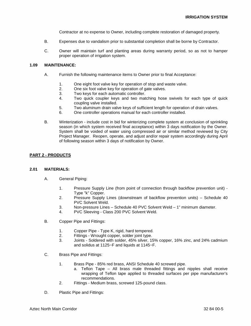
Contractor at no expense to Owner, including complete restoration of damaged property. B. Expenses due to vandalism prior to substantial completion shall be borne by Contractor. C. Owner will maintain turf and planting areas during warranty period, so as not to hamper
proper operation of irrigation system. 1.09 MAINTENANCE:
A. Furnish the following maintenance items to Owner prior to final Acceptance: 1. One eight foot valve key for operation of stop and waste valve. 2. One six foot valve key for operation of gate valves. 3. Two keys for each automatic controller. 4. Two quick coupler keys and two matching hose swivels for each type of quick
coupling valve installed. 5. Two aluminum drain valve keys of sufficient length for operation of drain valves. 6. One controller operations manual for each controller installed.
B. Winterization - include cost in bid for winterizing complete system at conclusion of sprinkling
season (in which system received final acceptance) within 3 days notification by the Owner. System shall be voided of water using compressed air or similar method reviewed by City Project Manager. Reopen, operate, and adjust and/or repair system accordingly during April of following season within 3 days of notification by Owner.
PART 2 - PRODUCTS 2.01 MATERIALS: A. General Piping:
1. Pressure Supply Line (from point of connection through backflow prevention unit) -
Type "k" Copper. 2. Pressure Supply Lines (downstream of backflow prevention units) – Schedule 40
PVC Solvent Weld. 3. Non-pressure Lines – Schedule 40 PVC Solvent Weld – 1” minimum diameter. 4. PVC Sleeving - Class 200 PVC Solvent Weld.
B. Copper Pipe and Fittings: 1. Copper Pipe - Type K, rigid, hard tempered. 2. Fittings - Wrought copper, solder joint type. 3. Joints - Soldered with solder, 45% silver, 15% copper, 16% zinc, and 24% cadmium
and solidus at 1125~F and liquids at 1145~F.
C. Brass Pipe and Fittings: 1. Brass Pipe - 85% red brass, ANSI Schedule 40 screwed pipe.
a. Teflon Tape – All brass male threaded fittings and nipples shall receive wrapping of Teflon tape applied to threaded surfaces per pipe manufacturer’s recommendations.
2. Fittings - Medium brass, screwed 125-pound class.
D. Plastic Pipe and Fittings:
IRRIGATION SYSTEM
Aztec North Main Corridor 32 84 00-6
1. Identification Markings:
a. Identify all pipe with following indelible markings: 1) Manufacturer's name. 2) Nominal pipe size. 3) Schedule of class. 4) Pressure rating. 5) NSF (National Sanitation Foundation) seal of approval. 6) Date of extrusion.
2. Solvent Weld Pipe - Manufactured from virgin polyvinyl chloride (PVC) compound in accordance with ASTM D2241 and ASTM D1784; cell classification 12454-B, Type 1, Grade 1. a. Fittings - Standard Wright, Schedule 40, injection molded PVC; complying
with ASTM D1784 and D2466, cell classification 12454-B. 1) Threads - Injection molded type (where required). 2) Tees and ells - Side gated.
b. Threaded Nipples - ASTM D2464, Schedule 80 with molded threads. c. Thread Sealant – All PVC male threaded fittings and nipples, excluding
marlex fittings, shall receive non-hardening thread sealant/paste containing no petroleum distillates applied to threaded surfaces per pipe manufacturer’s recommendations (Spears 75 Blue or equal).
d. Joint Cement and Primer - Type as recommended by manufacturer of pipe and fittings.
E. Drip Irrigation Systems:
1. Drip Tubing - Manufactured of flexible vinyl chloride compound conforming to ASTM
D1248, Type 1, Class C, Category 4, P14 and ASTM D3350 for PE 122111C. 2. Fittings - Type and diameter recommended by tubing manufacturer. 3. Drip Valve Assembly - Type and size shown on Drawings.
a. Basket Strainer - Plastic construction with 200 mesh nylon screen and integral. pre-set, non-adjustable pressure regulator (40 PSI).
b. Control Valve - 2 way, solenoid pilot operated type made of synthetic, non-corrosive material; diaphragm activated and slow closing. Include freely pivoted seat seal; retained (mounted) without attachment to diaphragm.
F. Gate Valves:
1. Gate Valves - Epoxy-coated iron construction; resilient wedge, IPS threads, and
non-rising stem with square-nut operator (Matco-Norca 10RS series). G. Quick Coupling Valves - Brass two-piece body designed for working pressure of 125 PSI;
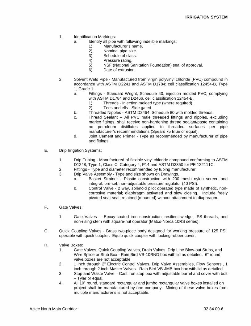
operable with quick coupler. Equip quick coupler with locking rubber cover. H. Valve Boxes:
1. Gate Valves, Quick Coupling Valves, Drain Valves, Drip Line Blow-out Stubs, and Wire Splice or Stub Box - Rain Bird VB-10RND box with lid as detailed. 6” round valve boxes are not acceptable
2. 1 inch through 2” Electric Control Valves, Drip Valve Assemblies, Flow Sensors,, 1 inch through 2 inch Master Valves - Rain Bird VB-JMB box box with lid as detailed.
3. Stop and Waste Valve – Cast iron stop box with adjustable barrel and cover with bolt – Tyler or equal.
4. All 10” round, standard rectangular and jumbo rectangular valve boxes installed on project shall be manufactured by one company. Mixing of these valve boxes from multiple manufacturer’s is not acceptable.
IRRIGATION SYSTEM
Aztec North Main Corridor 32 84 00-7
7. Valve box colors shall be green.
I. Electrical Control Wiring: 1. Low Voltage:
a. Electrical Control Wire - AWG UFUL approved No. 14, direct burial, single conductor, solid copper wire rated for 600 volts and polyethylene insulation.
b. Electrical Common Wire - AWG UFUL approved No. 14, direct burial, single conductor, solid copper wire rated for 600 volts and polyethylene insulation.
c. Wire Colors: 1) Control Wires - Red. 2) Common Wires - White. 3) Master Valve Wires - Blue. 4) Spare Control Wires - Black. 5) Spare Common Wires - Yellow.
d. If multiple controllers are utilized, and wire paths of different controllers cross each other, both common and control wires from each controller shall be different colors approved by City Project Manager.
e. Control Wire connections and splices shall be made with 3M DBR/Y-6 watertight wire splice.
f. Flow Sensor Cable – Paige Electric P7171D-A or pre-approved equal with 3M Gel-type connections installed within Preformed Super Serviseal Splice Kit.
2. High Voltage - Type required by local codes and ordinances, of proper size to accommodate needs of equipment serviced.
J. Automatic Controller - Size and type shown on Drawings; mounted as detailed. K. Electric Control Valves - Size and type shown on Drawings having manual flow adjustment
and manual operational nut with internal bleed. L. Sprinkler Heads - As indicated on Drawings. Fabricated riser units in accordance with
details on Drawings - with fittings and nipples of equal diameter as riser inlet in sprinkler body.
M. Backflow Preventer - Size and type indicated on Drawings; Brass, with 150 psi working
pressure.
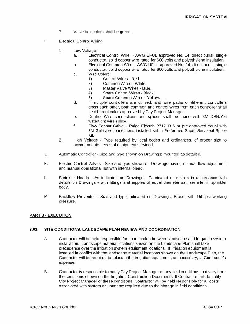
PART 3 - EXECUTION 3.01 SITE CONDITIONS, LANDSCAPE PLAN REVIEW AND COORDINATION
A. Contractor will be held responsible for coordination between landscape and irrigation system installation. Landscape material locations shown on the Landscape Plan shall take precedence over the irrigation system equipment locations. If irrigation equipment is installed in conflict with the landscape material locations shown on the Landscape Plan, the Contractor will be required to relocate the irrigation equipment, as necessary, at Contractor’s expense.
B. Contractor is responsible to notify City Project Manager of any field conditions that vary from
the conditions shown on the Irrigation Construction Documents. If Contractor fails to notify City Project Manager of these conditions, Contractor will be held responsible for all costs associated with system adjustments required due to the change in field conditions.
IRRIGATION SYSTEM
Aztec North Main Corridor 32 84 00-8
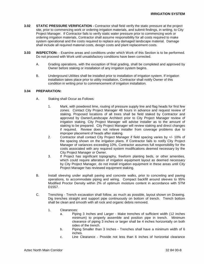
3.02 STATIC PRESSURE VERIFICATION - Contractor shall field verify the static pressure at the project site, prior to commencing work or ordering irrigation materials, and submit findings, in writing, to City Project Manager. If Contractor fails to verify static water pressure prior to commencing work or ordering irrigation materials, Contractor shall assume responsibility for all costs required to make system operational and the costs required to replace any damaged landscape material. Damage shall include all required material costs, design costs and plant replacement costs.
3.03 INSPECTION: - Examine areas and conditions under which Work of this Section is to be performed.
Do not proceed with Work until unsatisfactory conditions have been corrected.
A. Grading operations, with the exception of final grading, shall be completed and approved by Owner before staking or installation of any irrigation system begins.
B. Underground Utilities shall be installed prior to installation of irrigation system. If irrigation
installation takes place prior to utility installation, Contractor shall notify Owner of this condition in writing prior to commencement of irrigation installation.
3.04 PREPARATION: A. Staking shall Occur as Follows:
1. Mark, with powdered lime, routing of pressure supply line and flag heads for first few
zones. Contact City Project Manager 48 hours in advance and request review of staking. Proposed locations of all trees shall be field staked by Contractor and approved by Owner/Landscape Architect prior to City Project Manager review of irrigation staking. City Project Manager will advise installer as to the amount of staking to be prepared. City Project Manager will review staking and direct changes if required. Review does not relieve installer from coverage problems due to improper placement of heads after staking.
2. Contractor shall contact City Project Manager if field spacing varies by +/- 10% of the spacing shown on the irrigation plans. If Contractor fails to notify City Project Manager of variances exceeding 10%, Contractor assumes full responsibility for the costs associated with any required system modifications deemed necessary by the City Project Manager or Owner.
3. If Project has significant topography, freeform planting beds, or other amenities, which could require alteration of irrigation equipment layout as deemed necessary by City Project Manager, do not install irrigation equipment in these areas until City Project Manager has reviewed equipment staking.
B. Install sleeving under asphalt paving and concrete walks, prior to concreting and paving
operations, to accommodate piping and wiring. Compact backfill around sleeves to 95% Modified Proctor Density within 2% of optimum moisture content in accordance with STM D1557.
C. Trenching - Trench excavation shall follow, as much as possible, layout shown on Drawing.
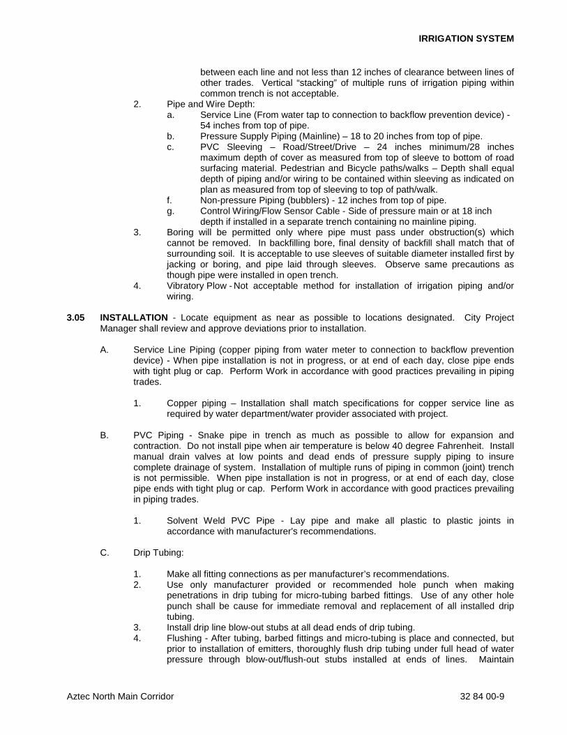
Dig trenches straight and support pipe continuously on bottom of trench. Trench bottom shall be clean and smooth with all rock and organic debris removed. 1. Clearances:
a. Piping 3 Inches and Larger - Make trenches of sufficient width (12 inches minimum) to properly assemble and position pipe in trench. Minimum clearance of piping 3 inches or larger shall be 4 inches horizontally on both sides of the trench.
b. Piping Smaller than 3 Inches - Trenches shall have a minimum width of 6 inches.
c. Line Clearance - Provide not less than 6 inches of horizontal clearance
IRRIGATION SYSTEM
Aztec North Main Corridor 32 84 00-9
between each line and not less than 12 inches of clearance between lines of other trades. Vertical “stacking” of multiple runs of irrigation piping within common trench is not acceptable.
2. Pipe and Wire Depth: a. Service Line (From water tap to connection to backflow prevention device) - 54 inches from top of pipe.
b. Pressure Supply Piping (Mainline) – 18 to 20 inches from top of pipe. c. PVC Sleeving – Road/Street/Drive – 24 inches minimum/28 inches
maximum depth of cover as measured from top of sleeve to bottom of road surfacing material. Pedestrian and Bicycle paths/walks – Depth shall equal depth of piping and/or wiring to be contained within sleeving as indicated on plan as measured from top of sleeving to top of path/walk.
f. Non-pressure Piping (bubblers) - 12 inches from top of pipe. g. Control Wiring/Flow Sensor Cable - Side of pressure main or at 18 inch
depth if installed in a separate trench containing no mainline piping. 3. Boring will be permitted only where pipe must pass under obstruction(s) which
cannot be removed. In backfilling bore, final density of backfill shall match that of surrounding soil. It is acceptable to use sleeves of suitable diameter installed first by jacking or boring, and pipe laid through sleeves. Observe same precautions as though pipe were installed in open trench.
4. Vibratory Plow - Not acceptable method for installation of irrigation piping and/or wiring.
3.05 INSTALLATION - Locate equipment as near as possible to locations designated. City Project
Manager shall review and approve deviations prior to installation. A. Service Line Piping (copper piping from water meter to connection to backflow prevention
device) - When pipe installation is not in progress, or at end of each day, close pipe ends with tight plug or cap. Perform Work in accordance with good practices prevailing in piping trades. 1. Copper piping – Installation shall match specifications for copper service line as
required by water department/water provider associated with project.
B. PVC Piping - Snake pipe in trench as much as possible to allow for expansion and contraction. Do not install pipe when air temperature is below 40 degree Fahrenheit. Install manual drain valves at low points and dead ends of pressure supply piping to insure complete drainage of system. Installation of multiple runs of piping in common (joint) trench is not permissible. When pipe installation is not in progress, or at end of each day, close pipe ends with tight plug or cap. Perform Work in accordance with good practices prevailing in piping trades. 1. Solvent Weld PVC Pipe - Lay pipe and make all plastic to plastic joints in
accordance with manufacturer's recommendations. C. Drip Tubing:
1. Make all fitting connections as per manufacturer’s recommendations. 2. Use only manufacturer provided or recommended hole punch when making
penetrations in drip tubing for micro-tubing barbed fittings. Use of any other hole punch shall be cause for immediate removal and replacement of all installed drip tubing.
3. Install drip line blow-out stubs at all dead ends of drip tubing. 4. Flushing - After tubing, barbed fittings and micro-tubing is place and connected, but
prior to installation of emitters, thoroughly flush drip tubing under full head of water pressure through blow-out/flush-out stubs installed at ends of lines. Maintain
IRRIGATION SYSTEM
Aztec North Main Corridor 32 84 00-10
flushing for 5 minutes through all blow-outs. D. Control Wiring:
1. Low Voltage Wiring:
a. Bury control wiring between controller and electric valves in pressure supply line trenches, strung as close as possible to main pipe lines with such wires to be consistently located below and to one side of pipe, or in separate trenches.
b. Bundle and tape all 24 volt irrigation wires with electrical tape at 10 foot intervals and lay with pressure supply line pipe to one side of the trench. Irrigation wiring installed above/over pressure supply line is not acceptable.
c. Provide an expansion loop at every pressure pipe angle fitting and every 500 feet. Form expansion loop by coiling wire bundle and lay formed coil in trench prior to backfilling.
d. Provide continuous loop of all spare wires within every valve box containing electric control valve or drip valve assembly. Construct loop within valve box by wrapping wire at least 8 times around a 3/4 inch pipe and withdrawing pipe.
e. Make all splices and electric control valve connections using 3M Company DBR/Y-6 watertight wire splice connector kits.
f. Install all control wire splices not occurring at control valve in a separate splice valve box.
g. Install one control wire for each control valve. 2. High Voltage Wiring for Automatic Controller:
a. Provide electric power and connection(s) to automatic controller. b. All electric work shall conform to local codes, ordinances, and authorities
having jurisdiction. All high voltage electrical work shall be performed by licensed electrician.
c. Electrical one-line diagrams required for permitting are to be prepared and paid by Contractor. Drawings shall be submitted to building department by Contractor.
E. Automatic Controller:
1. Install controller in accordance with manufacturer's instructions as detailed and
where shown on Drawings. 2. Connect electric control valve wiring to controller in numerical sequence as shown
on Drawings. 3. Owner shall approve final location of controller prior to installation. 4. Each controller shall be a dedicated separate ground wire and grounding rod or
grounding plate as detailed unless indicated otherwise on details. 5. All above ground conduit shall be rigid galvanized with appropriate fittings. All below
ground conduit shall be schedule 40 PVC. 6. All control wiring shall be neatly organized and bundled from terminal strip
connection to entrance to 24 volt wire conduit(s) exiting controller cabinet/pedestal. Utilize plastic, locking electrical ties at 12 inches o.c. within controller cabinets, pedestal and/or enclosures..
7. Exposed, bare ends of copper wiring connected to terminal strips shall not exceed 3/8” except where longer exposed length is required to complete connection.
8. Use of 18 ga. multi-strand cable is not permitted unless noted on details or approved by City Project Manager prior to installation.
9. All 24 volt wiring within controller enclosure/pedestal/cabinet shall be permanently identified via labeling indicating station number, spare wire, flow sensor wire, master valve wire, etc.
10. Furnish and install 9 volt back-up battery if controller can accept.
IRRIGATION SYSTEM
Aztec North Main Corridor 32 84 00-11
F. Electric Control Valves - Install cross-handle four inches below finished grade where shown
on Drawings as detailed. When grouped together, allow at least 12 inches between valve box sides. When installed adjacent to curbing and walks, allow 24 inches between valve box and walk/curb. Install each remote control valve in a separate valve box with box centered over valve assembly. Install individual valve box flush with grade.
G. Quick Coupling Valves - Install quick couplers on swing-joint assemblies as indicated on
construction details; plumb and flush to grade. Angled nipple relative to pressure supply line shall be no more than 45 degrees and no less than 10 degrees.
H. Drip Valve Assemblies - Install drip valve assembly as detailed. I. Drip Emitters - Stake all surface emitters as detailed and staked with acceptable tubing
stakes. J. Drain Valves - Install one manual drain valve on pressure supply line directly downstream of
backflow prevention device as detailed, K. Valve Boxes:
1. Install one valve box for each type of valve installed as detailed. Valve box
extensions are not acceptable except for master valves, pressure regulating valves, flow sensors or other irrigation equipment installed at depth of pressure mainline. Install gravel sump after compaction of all trenches. Place final portion of gravel inside valve box after valve box is backfilled and compacted.
2. Brand controller letter and station number on lid of each valve box. Letter and number size shall be no smaller than 1 inch and no greater in size than 1 1/2 inches. Depth of branding shall be no more than 1/8 inch into valve box lid.
L. Gate Valves - Install where shown on Drawings as detailed.
M. Backflow Prevention Device - Install as detailed at location designated on Drawings. N. Backfilling - Do not begin backfilling operations until required system tests have been
completed. Backfill shall not be done in freezing weather except with review by City Project Manager. Leave trenches slightly mounded to allow for settlement after backfilling is completed. Trenches shall be finish graded prior to walk-through of system by City Project Manager. 1. Materials - Excavated material is generally considered satisfactory for backfill
purposes. Backfill material shall be free of rubbish, vegetable matter, frozen materials, and stones larger than 1 inch in maximum dimension. Do not mix subsoil with topsoil. Material not suitable for backfill shall be hauled away. Contractor shall be responsible for providing suitable backfill if excavated material is unacceptable or not sufficient to meet backfill, compaction, and final grade requirements.
2. Do not leave trenches open for a period of more than 48 hours. Open excavations shall be protected in accordance with OSHA regulations.
3. Compact backfill in 6 inch lifts to 90% maximum density, determined in accordance with ASTM D155-7 utilizing the following methods: a. Mechanical tamping. b. Puddling or ponding. Puddling or ponding and/or jetting is prohibited within
20’-0" of building or foundation walls. O. Piping Under Paving:
IRRIGATION SYSTEM
Aztec North Main Corridor 32 84 00-12
1. Provide for a minimum cover of 24 inches between the top of the pipe and the bottom of the aggregate base for all pressure and non-pressure piping installed under asphaltic concrete or concrete paving.
2. Piping located under areas where asphalt or concrete paving will be installed shall be bedded with sand (a layer 6" below pipe and 6" above pipe).
3. Compact backfill material in 6" lifts at 90% maximum density determined in accordance with ASTM D155-7 using manual or mechanical tamping devices.
4. Piping under existing walks or concrete pavement shall be done by jacking, boring, or hydraulic driving, but where cutting or breaking of walks and/or concrete is necessary, it shall be done and replaced at not cost to Owner. Obtain permission to cut or break walks and/or concrete from Owner.
P. Water Supply and Point of Connection - Water supply shall be extended as shown from
water supply lines. Q. Water Meter – Water meter, associated pits/vaults, valves, piping, fittings and
appurtenances shall be furnished and installed by Contractor per local water provider standards and regulations.
3.06 FIELD QUALITY CONTROL:
A. Flushing - After piping, risers, and valves are in place and connected, but prior to installation of sprinkler heads, quick coupler assemblies, and hose valves, thoroughly flush piping system under full head of water pressure from dead end fittings. Maintain flushing for 5 minutes through furthermost valves. Cap risers after flushing.
B. Testing - Conduct tests in presence of City Project Manager. Arrange for presence of City
Project Manager 48 hours in advance of testing. Supply force pump and all other test equipment. 1. After backfilling, and installation of all control valves, fill pressure supply line with
water, and pressurize to 40 PSI over the designated static pressure or 120 PSI, whichever is greater, for a period of 2 hours. Pressure testing of pressure supply line utilizing compressed air is not acceptable.
2. Leakage, Pressure Loss - Test is acceptable if no loss of pressure is evident during the test period.
3. Leaks - Detect and repair leaks. 4. Retest system until test pressure can be maintained for duration of test. 5. Before final acceptance, pressure supply line shall remain under pressure for a
period of 48 hours. C. Walk-Through for Substantial Completion:
1. Arrange for City Project Manager's presence 48 hours in advance of walk-through. 2. Entire system shall be completely installed and fully operational prior to scheduling
of walk-through. This shall include all control valves capable of being operated via irrigation controller.
3. Electrically operate each zone in its entirety for City Project Manager at time of walk-through and additionally, open all valve boxes if directed.
4. City Project Manager shall generate a list of items to be corrected prior to Final Completion.
5. Furnish all materials and perform all work required to correct all inadequacies of coverage due to deviations from Contract Documents.
6. Supply City Project Manager with one set of full-size prints (not original drawings) of completed contractor-prepared irrigation as-built field drawings prior to start of substantial completion walk-through.

IRRIGATION SYSTEM
Aztec North Main Corridor 32 84 00-13
D. Walk-Through for Final Completion:
1. Arrange for City Project Manager’s presence 48 hours in advance of walk-through. 2. Show evidence to City Project Manager that Owner has received all accessories,
charts, record drawings, and equipment as required before Final Completion walk-through is scheduled.
3. Electrically operate each zone, in its entirety for City Project Manager at time of walk-through to insure correction of all incomplete items.
4. Items deemed not acceptable by City Project Manager shall be reworked to complete satisfaction of City Project Manager.
5. If after request to City Project Manager for walk-through for Final Completion of irrigation system, City Project Manager finds items during walk-through which have not been properly adjusted, reworked, or replaced as indicated on list of incomplete items from previous walk-through, Contractor shall be charged for all subsequent walk-throughs. Funds will be withheld from final payment and/or retainage to Contractor, in amount equal to additional time and expenses required by City Project Manager to conduct and document further walk-throughs as deemed necessary to insure compliance with Contract Documents.
3.07 ADJUSTING - Upon completion of installation, "fine-tune" entire system by regulating valves,
adjusting patterns and break-up arms, and setting pressure reducing valves at proper and similar pressure to provide optimum and efficient coverage. Flush and adjust all sprinkler heads for optimum performance and to prevent overspray onto walks, roadways, and buildings as much as possible. Heads of same type shall be operating at same pressure +/- 7%. A. If it is determined that irrigation adjustments will provide proper coverage, and improved
water distribution as determined by City Project Manager, contractor shall make such adjustments prior to Final Acceptance, as directed, at no additional cost to Owner. Adjustments may also include changes in nozzle sizes, degrees of arc, and control valve throttling.
B. All sprinkler heads shall be set perpendicular to finish grade unless otherwise noted on
Construction Plans or directed by City Project Manager. C. Areas which do not conform to designated operation requirements due to unauthorized
changes or poor installation practices shall be immediately corrected at no additional cost to the Owner.
3.08 CLEANING - Maintain continuous cleaning operation throughout duration of work. Dispose of, off-
site at no additional cost to Owner, all trash, debris and excess soil generated by installation of irrigation system.
END OF SECTION
Aztec North Main Submittals DHM Design – October 2020 LS013000-01
SUBMITTALS LS01 13 00 - 1
These Project Specifications and Drawings, the New Mexico Department of Transportation Standard Specifications and Drawings for Highway and Bridge Construction (2019 edition),City of Aztec Code, and New Mexico Standard Specifications for Public Works Construction shall be the governing documents for this project. When conflicts exist, the plans shall prevail followed by the governing documents in the above order of priority. Field conditions may exist that require changes to drawings. If such conditions are encountered, the governing documents shall prevail in the above order of priority.
SUPPLEMENTAL SPECIFICATIONS
Division 100 of the New Mexico Standard Specifications for Public Works Construction shall be revised for this project to include and/or substitute the following:
SECTION LS013000
LANDSCAPE SUBMITTALS
PART 1 - GENERAL 1.1 RELATED DOCUMENTS:
A. The General contract Conditions, Drawings and other Division 1 - Specification sections apply to work of this section.
B. New Mexico Standard Specifications for Public Works Construction, January 2019 Edition
1.2 DESCRIPTION: Section includes administrative and procedural requirements for submittal and
review of landscape product data, shop drawings, samples and similar items required by the specifications.
1.3 ADMINISTRATIVE SUBMITTALS: A. Refer to other Division-1 Sections and other Contract Documents for requirements for
administrative submittals. Such submittals include, but are not limited to:
Schedules Permits Applications for payment Schedule of Values Closeout documents Coordination drawings B. Such submittals are for information and record and do not require action on the part of
the Owner’s Representative except where not in conformity with the Contract documents. If such non-conformity is observed, the Owner’s Representative will notify the Contractor. Failure to be observed or to be notified by the Owner’s Representative does not relieve Contractor of compliance with Contract Documents.
Aztec North Main Submittals DHM Design – October 2020 LS013000-02
SUBMITTALS LS01 13 00 - 2
1.4 SUBMITTAL PROCEDURES: A. General: Make submittals from Contractor to the Owner’s Representative after
Contractor has reviewed each submittal and indicated his action thereon except for samples and selection submittals.
B. Scheduling:
1. Within 20 days after Notice to Proceed, prepare a separate listing and schedule
organized by related specification section number sequence, showing the principal work-related submittals and their initial submittal dates as required for coordination of the work.
2. Coordinate the submittal schedule with the construction schedule. Prepare the submittal schedule in chronological order.
C. Schedule Updating: Revise the schedule after each meeting or activity, where revisions
have been recognized or made. Issue the updated schedule concurrently with report of each meeting.
D. Coordination:
1. Coordinate the preparation and processing of submittals with the performance of
construction activities. Transmit each submittal sufficiently in advance of performance of related construction activities to avoid delay.
2. Coordinate each submittal with fabrication, purchasing, testing, delivery, other submittals and related activities that require sequential activity.
3. Coordinate transmittal of different types of submittals for related elements of Work so processing will not be delayed by the need to review submittals concurrently for coordination.
4. The Owner’s Representative reserves the right to withhold action on a submittal requiring coordination with other submittals until related submittals are received.
E. Processing:
1. Allow sufficient review time so that installation will not be delayed as a result of
the time required to process submittals, including time for re-submittals. 2. Allow five (5) days for processing each submittal. 3. No extension of Contract Time will be authorized because of failure to transmit
submittals to the Owner’s Representative sufficiently in advance of the Work to permit processing.
F. Submittal Transmittal:
1. Package each submittal appropriately for transmittal and handling. Transmit
each submittal from Contractor to the Owner’s Representative using a transmittal form. Submittals received from sources other than the Contractor will be returned without action.
2. On the transmittal, record relevant information and requests for data. On the form, or separate sheet, record deviations from Contract Document requirements, including minor variations and limitations. Include Contractor's certification that information complies with Contract Document requirements.
Aztec North Main Submittals DHM Design – October 2020 LS013000-03
SUBMITTALS LS01 13 00 - 3
1.5 SHOP DRAWINGS:
A. Submit newly prepared information, drawn to accurate scale. Highlight, encircle, or otherwise indicate deviations from the Contract Documents. Do not reproduce Contract Documents or copy standard information as the basis of Shop Drawings. Standard information prepared without specific reference to the Project shall not be considered to be a shop drawing. Shop Drawings include fabrication and installation drawings, setting diagrams, schedules, patterns, templates and similar drawings. Include the following information:
Dimensions Identification of products and materials included Compliance with specified standards Notation of coordination requirements Notation of dimensions established by field measurement
B. Submit three (3) copies of each shop drawing.
1.6 PRODUCT DATA:
A. Assemble Product Data into a single submittal for each element of construction or system. Product Data includes printed information such as manufacturer's installation instructions, catalog cuts, standard color charts, rough-in diagrams and templates, standard wiring diagrams and performance curves. Where Product Data must be specially prepared because standard printed data is not suitable for use, submit as "Shop Drawings". Where applicable include maintenance manual.
B. Mark each copy to show applicable choices and options. Where printed Product Data
includes information on several products, some of which are not required, mark copies to indicate the applicable information. Include the following information:
Manufacturer's printed recommendation.
Compliance with recognized trade association standards. Application of testing agency labels and seals. Notation of dimensions verified by field measurement. Notation of coordination requirements.
C. Do not submit Product Data until compliance with requirements of the Contract
Documents has been confirmed.
D. Submit copies as above specified for final shop drawings. Submit a cover letter to show Contractor's review and action. Where applicable, include additional copies for maintenance manuals.
E. Submit three (3) copies of product data. 1.7 SAMPLES:
A. Submit full-size, fully fabricated Samples cured and finished as specified and physically identical with the material or product proposed. Samples include partial sections of manufactured or fabricated components. Include the following:
Aztec North Main Submittals DHM Design – October 2020 LS013000-04
SUBMITTALS LS01 13 00 - 4
Generic description of the Sample. Sample source. Product name or name of manufacturer or supplier. Compliance with recognized standards. Availability and delivery time.
B. Submit Samples to the Owner’s Representative who will review them for a final check of
elements, and for a comparison of these characteristics between the final submittal and the actual component as delivered and installed.
1. Where variation in characteristics are inherent in the material or product
represented, submit multiple units (not less than 3), that show approximate limits of the variations.
2. Refer to other Sections for Samples to be returned to the Contractor for incorporation in the Work. Such Samples must be undamaged at time of use. On the transmittal, indicate special requests regarding disposition of Sample submittals.
C. Submittals: 1. Except for Samples illustrating assembly details, workmanship, fabrication
techniques, connections, operation and similar characteristics, submit three (3) sets: one will be returned marked with the action taken.
2. Maintain one (1) complete set of Samples, as returned, at the Project site, for quality comparisons throughout the course of construction.
D. Unless noncompliance with Contract Document provisions is observed, the submittal
may serve as the final submittal. PART 2 - PRODUCTS (Not applicable) PART 3 - EXECUTION (Not applicable)
END OF SECTION 013000
Aztec North Main Synthetic Wood Material DHM Design – October 2020 LS061525-01
SYNTHETIC WOOD MATERIAL LS06 15 25 - 1
SUPPLEMENTAL SPECIFICATIONS
The New Mexico Standard Specifications for Public Works Construction shall be revised for this project to include and/or substitute the following:
SECTION LS06 15 25
SYNTHETIC WOOD MATERIAL
PART 1 GENERAL
1.1 SECTION INCLUDES
A. Synthetic Wood Material bench and seat wall seats.
1.2 RELATED REQUIREMENTS
A. Drawings and general provisions of the Contract, including General and Supplementary Conditions and Division 1 Specification Sections, apply to this Section.
B. New Mexico Standard Specifications for Public Works Construction, January 2019 Edition
C. Section LS12 93 43 Gabion Benches and Seat Wall
1.3 REFERENCE STANDARDS
A. ASTM D696 - Standard Test Method for Coefficient of Linear Thermal Expansion of Plastics Between -30 degrees C and 30 Degrees C With a Vitreous Silica Dilatometer ; 2008.
B. ASTM D2047 - Standard Test Method for Static Coefficient of Friction of Polish-Coated Floor Surfaces as Measured by the James Machine ; 2004.
C. ASTM E84 - Standard Test Method for Surface Burning Characteristics of Building Materials ; 2010b.
1.4 SUBMITTALS
A. See Section LS 01 30 00 - Administrative Requirements, for submittal procedures. B. Product Data: Provide data indicating materials, component profiles, fastening methods,
jointing details, finishes, and accessories. 1. Preparation instructions and recommendations. 2. Storage and handling requirements and recommendations. 3. Installation methods.
C. Shop Drawings: Indicate seat framing system, loads and cambers, bearing details, and framed openings.
D. Samples of Synthetic Wood Material: Submit two samples of each size to be used illustrating surface texture, color, and finish.
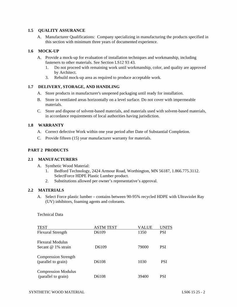
SYNTHETIC WOOD MATERIAL LS06 15 25 - 2
1.5 QUALITY ASSURANCE
A. Manufacturer Qualifications: Company specializing in manufacturing the products specified in this section with minimum three years of documented experience.
1.6 MOCK-UP
A. Provide a mock-up for evaluation of installation techniques and workmanship, including fasteners to other materials. See Section LS12 93 43. 1. Do not proceed with remaining work until workmanship, color, and quality are approved
by Architect. 3. Rebuild mock-up area as required to produce acceptable work.
1.7 DELIVERY, STORAGE, AND HANDLING
A. Store products in manufacturer's unopened packaging until ready for installation. B. Store in ventilated areas horizontally on a level surface. Do not cover with impermeable
materials. C. Store and dispose of solvent-based materials, and materials used with solvent-based materials,
in accordance requirements of local authorities having jurisdiction.
1.8 WARRANTY
A. Correct defective Work within one year period after Date of Substantial Completion. C. Provide fifteen (15) year manufacturer warranty for materials.
PART 2 PRODUCTS
2.1 MANUFACTURERS
A. Synthetic Wood Material: 1. Bedford Technology, 2424 Armour Road, Worthington, MN 56187, 1.866.775.3112.
SelectForce HDPE Plastic Lumber product. 2. Substitutions allowed per owner’s representative’s approval.
2.2 MATERIALS
A. Select Force plastic lumber – contains between 90-95% recycled HDPE with Ultraviolet Ray (UV) inhibitors, foaming agents and colorants.
Technical Data TEST ASTM TEST VALUE UNITS Flexural Strength D6109 1350 PSI Flexural Modulus Secant @ 1% strain D6109 79000 PSI Compression Strength (parallel to grain) D6108 1030 PSI Compression Modulus (parallel to grain) D6108 39400 PSI
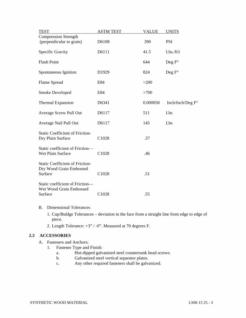
SYNTHETIC WOOD MATERIAL LS06 15 25 - 3
TEST ASTM TEST VALUE UNITS Compression Strength (perpendicular to grain) D6108 390 PSI Specific Gravity D6111 41.5 Lbs./ft3 Flash Point 644 Deg F° Spontaneous Ignition D1929 824 Deg F° Flame Spread E84 >200 Smoke Developed E84 >700 Thermal Expansion D6341 0.000058 Inch/Inch/Deg F° Average Screw Pull Out D6117 511 Lbs Average Nail Pull Out D6117 145 Lbs Static Coefficient of Friction- Dry Plain Surface C1028 .37 Static coefficient of Friction— Wet Plain Surface C1028 .46 Static Coefficient of Friction- Dry Wood Grain Embossed Surface C1028 .51 Static coefficient of Friction— Wet Wood Grain Embossed Surface C1028 .55 B. Dimensional Tolerances
1. Cup/Buldge Tolerances – deviation in the face from a straight line from edge to edge of piece. 2. Length Tolerance: +3” / -0”. Measured at 70 degrees F.
2.3 ACCESSORIES
A. Fasteners and Anchors: 1. Fastener Type and Finish: a. Hot-dipped galvanized steel countersunk head screws. b. Galvanized steel vertical separator plates. c. Any other required fasteners shall be galvanized.
SYNTHETIC WOOD MATERIAL LS06 15 25 - 4
PART 3 EXECUTION
3.1 EXAMINATION
A. Examine substrate conditions before beginning installation; verify dimensions and acceptability of substrate.
B. Do not proceed with installation until unacceptable conditions have been corrected. C. If substrate preparation is the responsibility of another installer, notify Owner’s Representative
of unsatisfactory preparation before proceeding.
3.2 PREPARATION
A. Coordinate placement of bearing items.
3.3 INSTALLATION - SEATS
A. Install synthetic wood material per manufacturer’s instructions, accommodating manufacturer’s recommended expansion joint spacing.
B. Install synthetic wood material into manufactured bracket frame with vertical separator plates. C. Use countersunk head screws for hidden fastening. D. Install hidden fasteners for end boards on each seat. E. Secure with manufacturer's proprietary fastener system. F. Obtain approval from Owner’s Representative prior to cutting decking to accommodate unique
conditions.
3.4 CLEANING
A. Clean installation per manufacturer recommendations. B. Provide Owner with two copies of cleaning and maintenance instructions.
3.5 PROTECTION
A. Protect installed products until completion of project. B. Touch-up, repair or replace damaged products before Substantial Completion.
END OF SECTION LS06 15 25
Aztec North Main Gabion Benches and Seat Wall DHM Design – October 2020 LS129343-01
SITE FURNISHINGS LS129343-01
SUPPLEMENTAL SPECIFICATIONS
The New Mexico Standard Specifications for Public Works Construction shall be revised for this project to include and/or substitute the following:
SECTION LS12 93 43
GABION BENCHES AND SEAT WALL
PART 1 - GENERAL
1.1 RELATED DOCUMENTS
A. Drawings and general provisions of the Contract, including General and Supplementary Conditions and Division 1 Specification Sections, apply to this Section.
B. New Mexico Standard Specifications for Public Works Construction, January 2019 Edition
C. Section LS44 00 00 Stone
D. Section LS31 37 00 Boulders and Bedding
E. Section LS06 15 25 Synthetic Wood Material
1.2 SUMMARY
A. This Section includes the following site and street furnishings: 1. Gabion Bench 2. Gabion Seat Wall
1.3 REFERENCE
A. ASTM A336 - Structural steel.
B. ASTM A307 - Low carbon steel externally and internally threaded fasteners.
C. ASTM A500 - Steel tubing cold form.
D. AWS D1.1 - Structural welding code.
E. ASTM A242 or ASTM A588 - Steel Plates and Structural Shapes.
F. ASTM A606 or ASTM A847 - Square or Rectangular Structural Steel Tubing
Aztec North Main Gabion Benches and Seat Wall DHM Design – October 2020 LS129343-02
SITE FURNISHINGS LS129343-02
1.4 SUBMITTALS
A. Product Data: For each type of product indicated on plans.
B. Shop Drawings: 1. For bench include plans, elevations, sections, details, and attachments to other work. 2. Four (4) sets of shop drawings prepared at an approved scale shall be submitted for
review. Once approved, shop drawings to be stamped by a structural engineer.
3. Indicate profiles, sizes, connection attachments, reinforcing, anchorage, size and type of fasteners and accessories
4. Indicate welded connections using standard AWS welding symbols. Indicate net weld
lengths.
C. Welding certificates.
D. Product Test Reports: Based on evaluation of comprehensive tests performed by a qualified testing agency, for bench, including finish, indicating compliance with referenced standards.
E. Samples: Submit duplicate samples of all materials and color samples to be furnished under this Section in size and form requested by the Owner.
F. Do not order materials or begin fabrication until Owner’s approval of submittals has been obtained.
G. Furnish to the Owner’s Authorized Representative, a certified statement that the shop-applied galvanizing and finishes conform to these Specifications including compliance with application thickness and adhesion.
1.5 QUALITY ASSURANCE
A. Installer Qualifications: Fabricator of products.
B. Welding Qualifications: Qualify procedures and personnel according to AWS D1.1/D1.1M, "Structural Welding Code – Steel.
C. Mockups: Build mockups to verify selections made under sample submittals and to demonstrate aesthetic effects and set quality standards for fabrication and installation.
1. Include one entire bench complying with requirements. 2. Include six feet of seat wall complying with requirements. 3. Approved mockups may become part of the completed work if undisturbed at time of
Substantial Completion.
D. Pre-installation Conference: Conduct conference at Project Site. 1.6 PRODUCT HANDLING AND STORAGE:
Aztec North Main Gabion Benches and Seat Wall DHM Design – October 2020 LS129343-03
SITE FURNISHINGS LS129343-03
A. Materials shall be carefully handled and stored under cover in manner to prevent deformation
and damage to the materials and to shop finishes, and to prevent rusting and the accumulation of foreign matter on the metal work. All such work shall be repaired and cleaned before erec-tion.
PART 2 - PRODUCTS
2.1 MATERIALS:
A. Steel Plates and Structural Shapes: ASTM A242 or ASTM A588
B. Square or Rectangular Structural Steel Tubing: Shall conform to ASTM A606 or ASTM A847
Grade.
C. Bolts, nuts and washers; compatible galvanized material.
D. Welding Materials: AWS D1.1; type required for materials being welded. E. Galvanized Gabion: 3’ x 3’ x 1.5’ ht.; 2” x 2” grid openings, 6 gauge. Supplied by Gabion Sup-
ply, ph: 1-866-391-6295 or www.gabionsupply.com or approved equal.
F. Synthetic Wood Material: 1 ½” x 3”
G. Metal Header/Steel Edger. Ryerson (painted) 1/4” thick x 6” or approved equal.
2.2 FABRICATIONS:
A. Shop fabrication and tolerances shall conform to requirement of AWS and AISC specifications and shall be equal to the best practice in modern sheet metal and structural steel shops.
B. Verify dimensions on-site prior to shop fabrication. C. Fabricate items with joints tightly fitted and secured. Joints exposed to weather shall be
formed to exclude water. D. Fit and shop assemble in largest practical sections, for delivery to site. Curved work shall
be to true radii. E. Grind exposed welds flush and smooth with adjacent finished surface. Ease exposed
edges to small uniform radius. F. Make exposed joints butt tight, flush; and hairline.
Aztec North Main Gabion Benches and Seat Wall DHM Design – October 2020 LS129343-04
SITE FURNISHINGS LS129343-04
G. Supply components required for anchorage of metal fabrications. Fabricate anchorage
and related components of same material and finish as metal fabrication, except where specifically noted otherwise.
H. Do all cutting, punching, drilling and tapping required for attachment of hardware and of
work of other Sections where so indicated or where directions for same are given prior to, or with approval of, shop drawings.
I. Live loads shall be not less than the minimum required by code. Where specific live
loads are not set forth in the codes applicable to this work, and are not given on the Drawings, designs shall be such as to support live loads without deflection of more than L/360 of length of any member and without permanent deformation, all with a safety fac-tor of not less than 2-1/2 to 1.
J. Zinc Electroplate: Components shall be zinc electroplated including all bolts, nuts, wash-
ers and other related ferrous metal items used herewith. 2.3 FINISH:
A. Clean surfaces of dirt, scale, grease and foreign matter prior to finishing. Power tool clean in accordance with SSPC SP3. Remove grease and oil with recommended solvents.
B. Gabions to be galvanized steel.
PART 3 - EXECUTION 3.1 PREPARATION:
A. Obtain Owner’s Authorized Representative’s approval prior to site cutting or making ad-justments not scheduled.
B. Make provision for erection loads with temporary bracing. Keep work in alignment. C. Supply items required to be cast into concrete with setting templates, to appropriate sec-
tion. 3.2 INSTALLATION:
A. Install items plumb, level and square, accurately fitted, free from distortion or defects.
END OF SECTION LS12 93 00
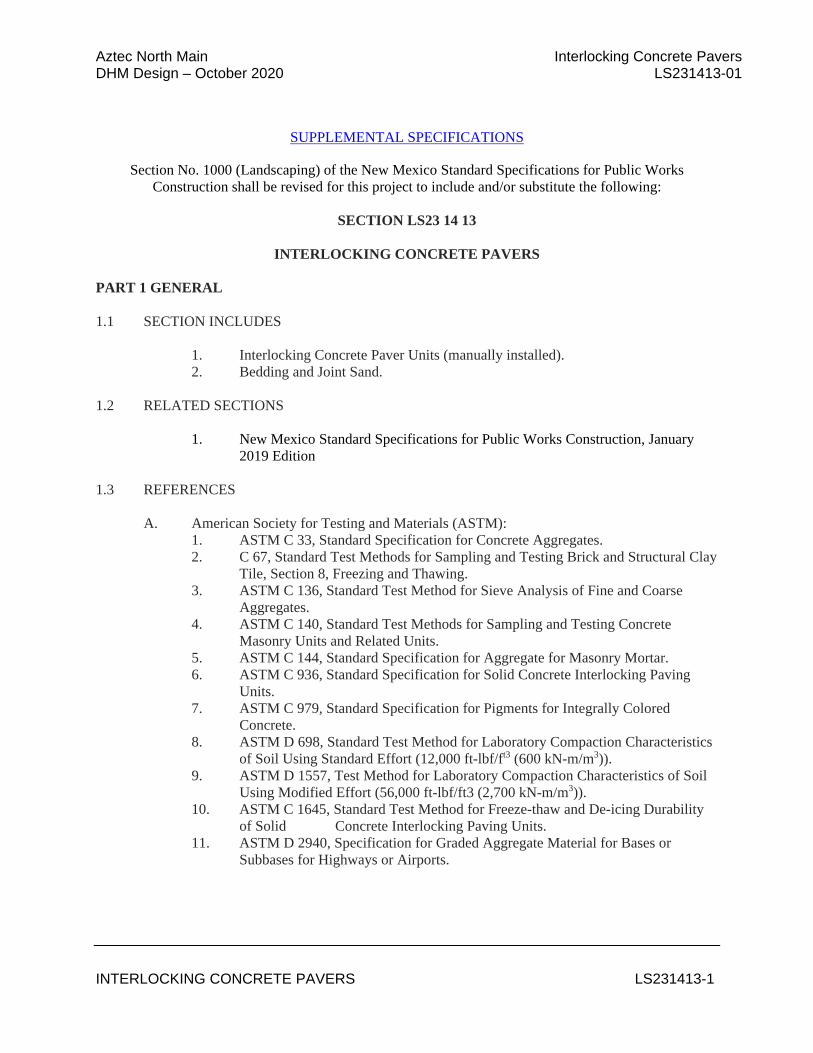
Aztec North Main Interlocking Concrete Pavers DHM Design – October 2020 LS231413-01
INTERLOCKING CONCRETE PAVERS LS231413-1
SUPPLEMENTAL SPECIFICATIONS
Section No. 1000 (Landscaping) of the New Mexico Standard Specifications for Public Works Construction shall be revised for this project to include and/or substitute the following:
SECTION LS23 14 13
INTERLOCKING CONCRETE PAVERS
PART 1 GENERAL 1.1 SECTION INCLUDES 1. Interlocking Concrete Paver Units (manually installed). 2. Bedding and Joint Sand. 1.2 RELATED SECTIONS
1. New Mexico Standard Specifications for Public Works Construction, January 2019 Edition
1.3 REFERENCES A. American Society for Testing and Materials (ASTM):
1. ASTM C 33, Standard Specification for Concrete Aggregates. 2. C 67, Standard Test Methods for Sampling and Testing Brick and Structural Clay
Tile, Section 8, Freezing and Thawing. 3. ASTM C 136, Standard Test Method for Sieve Analysis of Fine and Coarse
Aggregates. 4. ASTM C 140, Standard Test Methods for Sampling and Testing Concrete
Masonry Units and Related Units. 5. ASTM C 144, Standard Specification for Aggregate for Masonry Mortar. 6. ASTM C 936, Standard Specification for Solid Concrete Interlocking Paving
Units. 7. ASTM C 979, Standard Specification for Pigments for Integrally Colored
Concrete. 8. ASTM D 698, Standard Test Method for Laboratory Compaction Characteristics
of Soil Using Standard Effort (12,000 ft-lbf/ft3 (600 kN-m/m3)). 9. ASTM D 1557, Test Method for Laboratory Compaction Characteristics of Soil
Using Modified Effort (56,000 ft-lbf/ft3 (2,700 kN-m/m3)). 10. ASTM C 1645, Standard Test Method for Freeze-thaw and De-icing Durability
of Solid Concrete Interlocking Paving Units. 11. ASTM D 2940, Specification for Graded Aggregate Material for Bases or
Subbases for Highways or Airports.
Aztec North Main Interlocking Concrete Pavers DHM Design – October 2020 LS231413-02
INTERLOCKING CONCRETE PAVERS LS231413-2
B. Interlocking Concrete Pavement Institute (ICPI): 1. ICPI Tech Spec Technical Bulletins 1.4 SUBMITTALS
A. In accordance with Conditions of the Contract and Division 1 Submittal Procedures Section.
B. Manufacturer’s drawings and details: Indicate perimeter conditions, relationship to adjoining materials and assemblies, concrete paver layout, patterns, color arrangement, installation and setting details.
C. Sieve analysis per ASTM C 136 for grading of bedding and joint sand. D. Concrete pavers:
1. Four representative full-size samples of each paver type, thickness, color, finish that indicate the range of color variation and texture expected in the finished installation. Color(s) selected by Landscape Architect from manufacturer’s available colors. Paver samples shall be available for comparison with colored concrete samples.
2. Accepted samples become the standard of acceptance for the work. 3. Test results from an independent testing laboratory for compliance of concrete
pavers with ASTM C 936. 4. Manufacturer’s catalog product data, installation instructions, and material safety
data sheets for the safe handling of the specified materials and products. E. Paver Installation Subcontractor:
1. A copy of Subcontractor’s current certificate from the Interlocking Concrete Pavement Institute Concrete Paver Installer Certification program.
2. Job references from projects of a similar size and complexity. Provide Owner/Client/General Contractor names, postal address, phone, fax, and email address.
1.5 QUALITY ASSURANCE
A. Paving Subcontractor Qualifications: 1. Utilize an installer having successfully completed concrete paver installation
similar in design, material, and extent indicated on this project. 2. Utilize an installer holding a current certificate from the Interlocking Concrete
Pavement Institute Concrete Paver Installer Certification program. B. Regulatory Requirements and Approvals: Comply with requirements of state and local
building codes and with rules and regulations relating to accessibility. C. Mock-Ups:
1. Install a 7 ft x 7 ft (2 x 2 m) paver area. 2. Use this area to determine surcharge of the bedding sand layer, joint sizes, lines,
laying pattern(s), color(s) and texture of the job. 3. This area will be used as the standard by which the work will be judged. 4. Subject to acceptance by owner, mock-up may be retained as part of finished
work. 5. If mock-up is not retained, remove and properly dispose of mock-up.
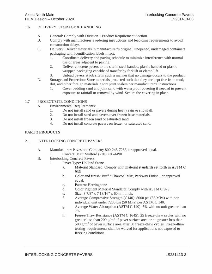
Aztec North Main Interlocking Concrete Pavers DHM Design – October 2020 LS231413-03
INTERLOCKING CONCRETE PAVERS LS231413-3
1.6 DELIVERY, STORAGE & HANDLING A. General: Comply with Division 1 Product Requirement Section. B. Comply with manufacturer’s ordering instructions and lead-time requirements to avoid construction delays. C. Delivery: Deliver materials in manufacturer’s original, unopened, undamaged containers packaging with identification labels intact.
1. Coordinate delivery and paving schedule to minimize interference with normal use of areas adjacent to paving.
2. Deliver concrete pavers to the site in steel banded, plastic banded or plastic wrapped packaging capable of transfer by forklift or clamp lift.
3. Unload pavers at job site in such a manner that no damage occurs to the product. D. Storage and Protection: Store materials protected such that they are kept free from mud,
dirt, and other foreign materials. Store joint sealers per manufacturer’s instructions. 1. Cover bedding sand and joint sand with waterproof covering if needed to prevent exposure to rainfall or removal by wind. Secure the covering in place. 1.7 PROJECT/SITE CONDITIONS A. Environmental Requirements: 1. Do not install sand or pavers during heavy rain or snowfall. 2. Do not install sand and pavers over frozen base materials. 3. Do not install frozen sand or saturated sand. 4. Do not install concrete pavers on frozen or saturated sand. PART 2 PRODUCTS 2.1 INTERLOCKING CONCRETE PAVERS A. Manufacturer: Pavestone Company 800-245-7283, or approved equal. 1. Contact: Matt Mulford (720) 236-4490. B. Interlocking Concrete Pavers: 1. Paver Type: Holland Stone.
a. Material Standard: Comply with material standards set forth in ASTM C 936.
b. Color and finish: Buff / Charcoal Mix, Parkway Finish.; or approved equal.
c. Pattern: Herringbone d. Color Pigment Material Standard: Comply with ASTM C 979. e. Size: 3 7/8” x 7 13/16” x 60mm thick. f. Average Compressive Strength (C140): 8000 psi (55 MPa) with non
individual unit under 7200 psi (50 MPa) per ASTM C 140. g. Average Water Absorption (ASTM C 140): 5% with no unit greater than
7%. h. Freeze/Thaw Resistance (ASTM C 1645): 25 freeze-thaw cycles with no
greater loss than 200 g/m2 of paver surface area or no greater loss than 500 g/m2 of paver surface area after 50 freeze-thaw cycles. Freeze-thaw testing requirements shall be waived for applications not exposed to freezing conditions.
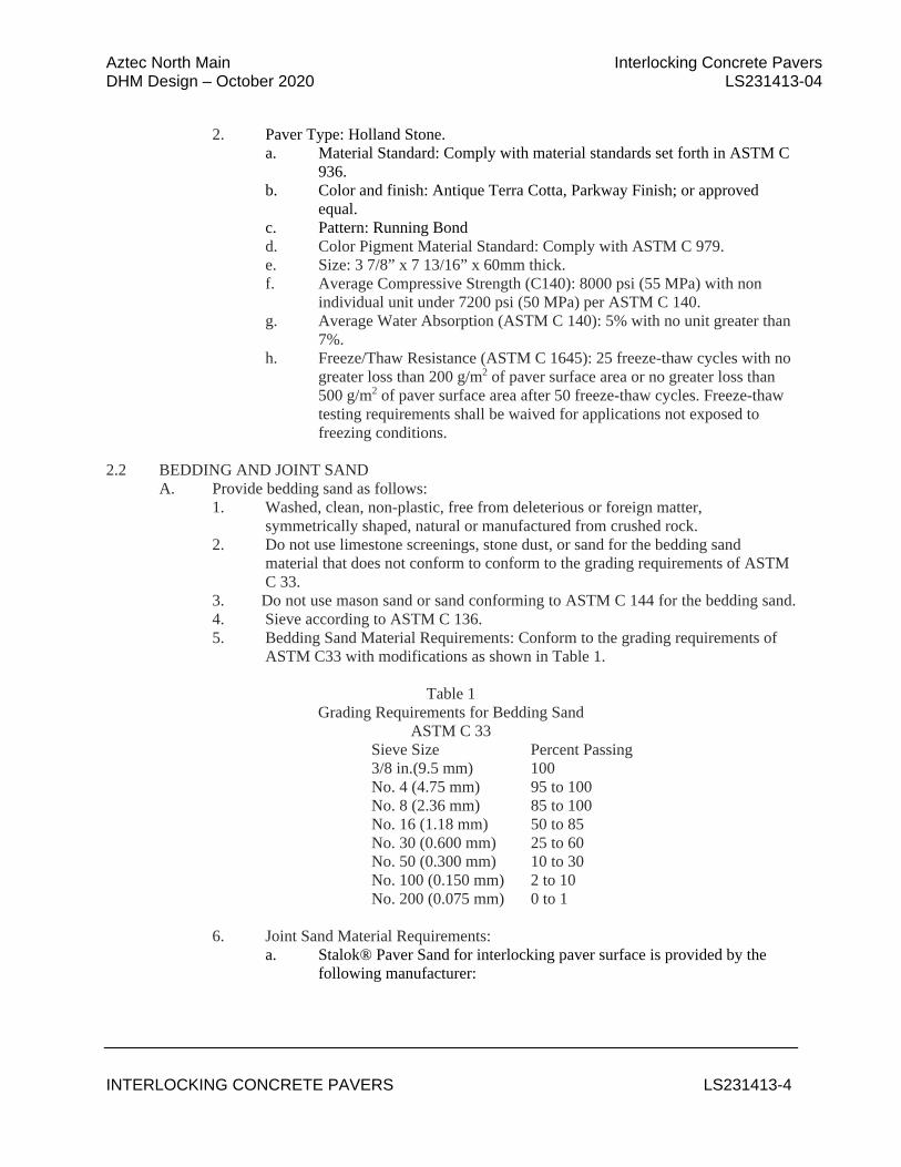
Aztec North Main Interlocking Concrete Pavers DHM Design – October 2020 LS231413-04
INTERLOCKING CONCRETE PAVERS LS231413-4
2. Paver Type: Holland Stone.
a. Material Standard: Comply with material standards set forth in ASTM C 936.
b. Color and finish: Antique Terra Cotta, Parkway Finish; or approved equal.
c. Pattern: Running Bond d. Color Pigment Material Standard: Comply with ASTM C 979. e. Size: 3 7/8” x 7 13/16” x 60mm thick. f. Average Compressive Strength (C140): 8000 psi (55 MPa) with non
individual unit under 7200 psi (50 MPa) per ASTM C 140. g. Average Water Absorption (ASTM C 140): 5% with no unit greater than
7%. h. Freeze/Thaw Resistance (ASTM C 1645): 25 freeze-thaw cycles with no
greater loss than 200 g/m2 of paver surface area or no greater loss than 500 g/m2 of paver surface area after 50 freeze-thaw cycles. Freeze-thaw testing requirements shall be waived for applications not exposed to freezing conditions.
2.2 BEDDING AND JOINT SAND A. Provide bedding sand as follows:
1. Washed, clean, non-plastic, free from deleterious or foreign matter, symmetrically shaped, natural or manufactured from crushed rock.
2. Do not use limestone screenings, stone dust, or sand for the bedding sand material that does not conform to conform to the grading requirements of ASTM C 33.
3. Do not use mason sand or sand conforming to ASTM C 144 for the bedding sand. 4. Sieve according to ASTM C 136. 5. Bedding Sand Material Requirements: Conform to the grading requirements of
ASTM C33 with modifications as shown in Table 1.
Table 1 Grading Requirements for Bedding Sand
ASTM C 33 Sieve Size Percent Passing 3/8 in.(9.5 mm) 100 No. 4 (4.75 mm) 95 to 100 No. 8 (2.36 mm) 85 to 100 No. 16 (1.18 mm) 50 to 85 No. 30 (0.600 mm) 25 to 60 No. 50 (0.300 mm) 10 to 30 No. 100 (0.150 mm) 2 to 10 No. 200 (0.075 mm) 0 to 1 6. Joint Sand Material Requirements:
a. Stalok® Paver Sand for interlocking paver surface is provided by the following manufacturer:
Aztec North Main Interlocking Concrete Pavers DHM Design – October 2020 LS231413-05
INTERLOCKING CONCRETE PAVERS LS231413-5
i. Stabilizer Solutions, Inc. 33 S. 28th St., Phoenix, AZ 85034; phone (602) 225-5900, (800) 336-2468; fax (602) 225-5902; website www.stabilizersolutions.com; email [email protected]
ii. Officially licensed blender of Stalok® Paver Sand by Stabilizer Solutions, Inc.
b. Stalok® Paver Sand or approved equal: i. Non-toxic, porous, polymeric joint sand that is comprised of a
dry, washed, quartz sand and binder. PART 3 EXECUTION 3.1 EXAMINATION A. Acceptance of Site Verification of Conditions:
1. General Contractor shall inspect, accept and certify in writing to the paver installation subcontractor that site conditions meet specifications for the following items prior to installation of interlocking concrete pavers. a. Verify that subgrade preparation, compacted density and elevations
conform to specified requirements. b. Verify that Aggregate base materials, thickness, compacted density,
surface tolerances and elevations conform to specified requirements. d. Provide written density test results for soil subgrade, aggregate base
materials to the Owner, General Contractor and paver installation subcontractor.
e. Verify that Concrete Sub-Slab material, thickness, surface tolerances and elevations conform to specified requirements.
f. Verify location, type, and elevations of edge restraints, utility structures, and drainage inlets.
2. Do not proceed with installation of bedding sand and interlocking concrete pavers until subgrade concrete sub-slab, soil and base conditions are corrected by the General Contractor or designated subcontractor.
3.2 PREPARATION
A. Verify base is dry, certified by General Contractor as meeting material, installation and grade specifications.
B. Verify that base is ready to support sand, pavers and imposed loads. C. Verify Edge Restraint:
1. Verify edge restraints are installed per the drawings at the indicated elevations. 3.3 INSTALLATION
A. Spread bedding sand evenly over the base course and screed to a nominal 1 in. (25 mm) thickness, not exceeding 1 1/2 in. (40 mm) thickness. Spread bedding sand evenly over the base course and screed rails, using the rails and/or edge restraints to produce a nominal 1 in. (25 mm) thickness, allowing for specified variation in the base surface. 1. Do not disturb screeded sand. 2. Screeded area shall not substantially exceed that which is
covered by pavers in one day.
Aztec North Main Interlocking Concrete Pavers DHM Design – October 2020 LS231413-06
INTERLOCKING CONCRETE PAVERS LS231413-6
3. Do not use bedding sand to fill depressions in the base surface.
B. Lay pavers in pattern(s) shown on drawings. Place units hand tight without using hammers. Make horizontal adjustments to placement of laid pavers with rubber hammers and pry bars as required.
C. Provide joints between pavers between 1/16 in. and 3/16 in. (2 and 5 mm) wide. No more than 5% of the joints shall exceed [1/4 in. (6 mm)] wide to achieve straight bond lines.
D. Joint (bond) lines shall not deviate more than ±1/2 in. (±15 mm) over 50 ft. (15 m) from string lines.
E. Fill gaps at the edges of the paved area with cut pavers or edge units. F. Cut pavers to be placed along the edge with a double blade paver splitter or masonry saw. G. Adjust bond pattern at pavement edges such that cutting of edge pavers is minimized. All
cut pavers shall be no smaller than one-third of a whole paver. H. Keep skid steer and forklift equipment off newly laid pavers that have not received initial
compaction and joint sand. I. Use a low-amplitude plate compactor capable of at least minimum of 4,000 lbf (18 kN) at
a frequency of 75 to 100 Hz to vibrate the pavers into the sand. Remove any cracked or damaged pavers and replace with new units.
J. Spread joint Sand on paver surface and sweep into joint. K. Compact joint Sand with vibratory plate compactor. L. Simultaneously spread, sweep and compact dry joint sand into joints continuously until
full. This will require at least 4 to 6 passes with a plate compactor. Do not compact within 6 ft (2 m) of unrestrained edges of paving units.
M. All work within 6 ft. (2 m) of the laying face shall be left fully compacted with sand-filled joints at the end of each day or compacted upon acceptance of the work. Cover the laying face or any incomplete areas with plastic sheets overnight if not closed with cut and compacted pavers with joint sand to prevent exposed bedding sand from becoming saturated from rainfall.
N. Remove excess sand from surface with broom or mechanical blower when installation is complete.
O. Watering 1. Moisten only the top layer of joint sand with a fine mist of water. 2. Thoroughly soak the joint Sand without generating run-off of material 3. Check moisture penetration with a screwdriver or knife. 4. If entire joint is not moist, add more water until full moisture penetration is achieved. 5. Allow the joint Sand to dry for up to 24 hours or until firm.
3.4 FIELD QUALITY CONTROL
A. The final surface tolerance from grade elevations shall not deviate more than ±3/8 in. (±10 mm) under a 10 ft (3 m) straightedge.
B. Check final surface elevations for conformance to drawings. C. The surface elevation of pavers shall be 1/8 in. to 1/4 in. (3 to 6 mm) above adjacent
drainage inlets, concrete collars or channels. D. Lippage: No greater than 1/8 in. (3 mm) difference in height between adjacent pavers.

Aztec North Main Interlocking Concrete Pavers DHM Design – October 2020 LS231413-07
INTERLOCKING CONCRETE PAVERS LS231413-7
3.5 PROTECTION A. After work in this section is complete, the General Contractor shall be responsible for
protecting work from damage due to subsequent construction activity on the site. 3.5 MAINTENANCE
A. Remove debris such as paper, grass clippings, leaves, or other organic material by sweeping, mechanical blowing or power washing. 1. When power washing use a fan spray nozzle and avoid direct spray on joint Sand for
long periods. 2. Do not power wash joint Sand when the sand is wet.
3.6 REPAIRS
A. If cracking or loose material develops, remove loose material, add joint Sand and water to depth of joint.
END OF SECTION
Aztec North Main Boulders and Bedding DHM Design – October 2020 LS313700-01
BOULDERS AND BEDDING LS313700-1
SUPPLEMENTAL SPECIFICATIONS
Section No. 1000 (Landscaping) of the New Mexico Standard Specifications for Public Works Construction and NMDOT Standard specification Section 303000 shall be revised for this project to
include and/or substitute the following:
SECTION LS31 37 00
BOULDERS AND BEDDING
PART 1 GENERAL
1.1 SECTION INCLUDES
A. The work includes excavation, grading, and installation of boulders, and bedding placed at the locations shown on the drawings. The materials to be used and the construction of such structures shall be as specified herein.
1.2 RELATED SECTIONS
A. The following is a list of SPECIFICATIONS, which may be related to this section:
1. New Mexico Standard Specifications for Public Works Construction, January 2019
Edition 2. NMDOT Standard Specification 303000.
1.3 REFERENCES
A. The following is a list of standards which may be referenced in this section:
1. American Association of State Highway and Transportation Officials
(AASHTO):
a. T85, Standard Method of Test for Specific Gravity and Absorption of Coarse Aggregate.
b. T96, Standard Method of Test for Resistance to Degradation of Small-
Size Coarse Aggregate by Abrasion and Impact in the Los Angeles Machine.
c. T103, Standard Method of Test for Soundness of Aggregates by
Freezing and Thawing.
d. T104, Standard Method of Test for Soundness of Aggregate by Use of Sodium Sulfate or Magnesium Sulfate.
e. T248, Reducing Field Samples of Aggregate Test Size.
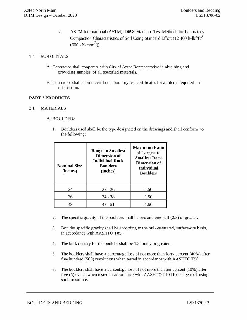
Aztec North Main Boulders and Bedding DHM Design – October 2020 LS313700-02
BOULDERS AND BEDDING LS313700-2
2. ASTM International (ASTM): D698, Standard Test Methods for Laboratory
Compaction Characteristics of Soil Using Standard Effort (12 400 ft-lbf/ft3
(600 kN-m/m3)). 1.4 SUBMITTALS
A. Contractor shall cooperate with City of Aztec Representative in obtaining and
providing samples of all specified materials.
B. Contractor shall submit certified laboratory test certificates for all items required in this section.
PART 2 PRODUCTS
2.1 MATERIALS
A. BOULDERS
1. Boulders used shall be the type designated on the drawings and shall conform to
the following:
Nominal Size (inches)
Range in Smallest
Dimension of Individual Rock
Boulders (inches)
Maximum Ratio of Largest to
Smallest Rock Dimension of
Individual Boulders
24 22 - 26 1.50
36 34 - 38 1.50
48 45 - 51 1.50
2. The specific gravity of the boulders shall be two and one-half (2.5) or greater.
3. Boulder specific gravity shall be according to the bulk-saturated, surface-dry basis, in accordance with AASHTO T85.
4. The bulk density for the boulder shall be 1.3 ton/cy or greater.
5. The boulders shall have a percentage loss of not more than forty percent (40%) after
five hundred (500) revolutions when tested in accordance with AASHTO T96.
6. The boulders shall have a percentage loss of not more than ten percent (10%) after five (5) cycles when tested in accordance with AASHTO T104 for ledge rock using sodium sulfate.
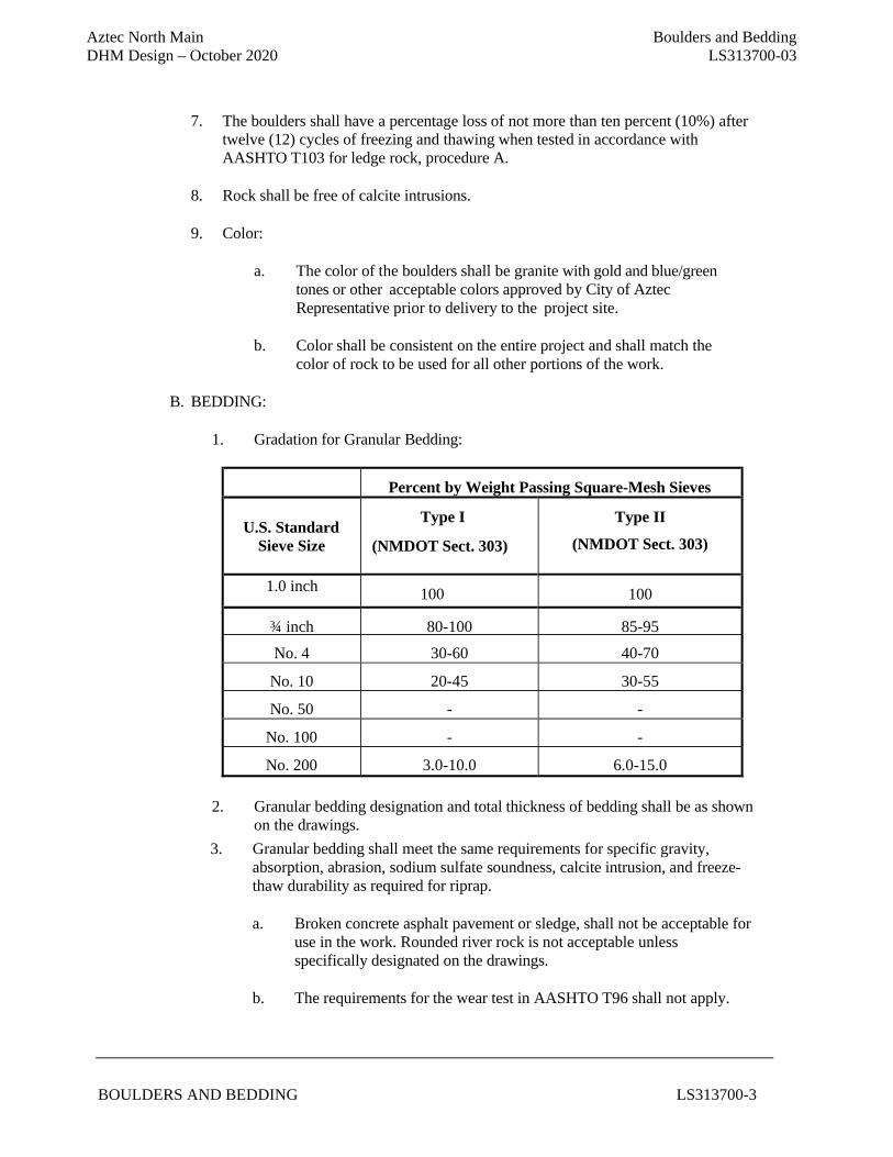
Aztec North Main Boulders and Bedding DHM Design – October 2020 LS313700-03
BOULDERS AND BEDDING LS313700-3
7. The boulders shall have a percentage loss of not more than ten percent (10%) after
twelve (12) cycles of freezing and thawing when tested in accordance with AASHTO T103 for ledge rock, procedure A.
8. Rock shall be free of calcite intrusions.
9. Color:
a. The color of the boulders shall be granite with gold and blue/green
tones or other acceptable colors approved by City of Aztec Representative prior to delivery to the project site.
b. Color shall be consistent on the entire project and shall match the
color of rock to be used for all other portions of the work.
B. BEDDING:
1. Gradation for Granular Bedding:
Percent by Weight Passing Square-Mesh Sieves
U.S. Standard Sieve Size
Type I
(NMDOT Sect. 303)
Type II
(NMDOT Sect. 303)
1.0 inch 100 100
¾ inch 80-100 85-95
No. 4 30-60 40-70
No. 10 20-45 30-55
No. 50 - -
No. 100 - -
No. 200 3.0-10.0 6.0-15.0
2. Granular bedding designation and total thickness of bedding shall be as shown on the drawings.
3. Granular bedding shall meet the same requirements for specific gravity, absorption, abrasion, sodium sulfate soundness, calcite intrusion, and freeze- thaw durability as required for riprap.
a. Broken concrete asphalt pavement or sledge, shall not be acceptable for
use in the work. Rounded river rock is not acceptable unless specifically designated on the drawings.
b. The requirements for the wear test in AASHTO T96 shall not apply.
Aztec North Main Boulders and Bedding DHM Design – October 2020 LS313700-04
BOULDERS AND BEDDING LS313700-4
PART 3 EXECUTION
3.1 PREPARATION
A. Contractor shall excavate areas to receive boulders to the specified depth (bedding
material is not required for boulders).
B. Contractor shall excavate areas to receive to the specified depth.
C. Subgrade Materials:
1. The subgrade materials shall be stable.
2. If unsuitable materials are encountered, they shall be removed and replaced as Muck Excavation in accordance with New Mexico Standard Specifications for Public Works Construction, January 2019 Edition, for subgrade that has been excavated in undisturbed soil.
D. Additional Compaction:
1. Additional compaction shall not be required unless specified by City of Aztec
Representative.
2. When subgrade is built up with embankment material it shall be compacted to ninety five percent (95%) maximum density (ASTM D698).
E. Bedding:
1. After an acceptable subgrade is established, bedding shall be immediately
placed and leveled.
2. Immediately following the placement of the bedding material,any pavement shall be placed.
3. If bedding material is disturbed for any reason, it shall be replaced and graded
at Contractor’s expense.
4. Contamination:
a. In-place bedding materials shall not be contaminated with soils, debris or vegetation before pavement is placed.
b. If contaminated, the bedding material shall be removed and replaced at
Contractor’s expense.
3.2 PLACEMENT
A. FEATURE BOULDERS
Aztec North Main Boulders and Bedding DHM Design – October 2020 LS313700-05
BOULDERS AND BEDDING LS313700-5
1. Feature Boulders serve an aesthetic function and as such shall be placed and
rotated into final position as directed by City of Aztec Representative in order to achieve the desired result. Care shall be taken in handling of feature boulders to minimize scratching, marring, and chipping damage to the boulders. Contractor shall use straps and/or pads to minimize damage to boulders.
3.3 REJECTION OF WORK AND MATERIALS:
A. City of Aztec Representative will reject placed boulders and bedding that do not
conform to this section. Contractor shall immediately remove and re-lay the boulders and bedding to conform to specifications.
B. Boulders and bedding shall be rejected, which is either delivered to the job site or
placed, that does not conform to this section.
C. Rejected boulders and bedding shall be removed from the project site by contractor at
contractor’s expense.
END OF SECTION
Aztec North Main Crusher Fines Paving DHM Design – October 2020 LS321540-01
CRUSHER FINES PAVING LS321540 - 1 of 6
SUPPLEMENTAL SPECIFICATIONS
Section 300 (Streets and Related Work) of the New Mexico Standard Specifications for Public Works Construction shall be revised for this project to include and/or substitute the following:
SECTION LS32 15 40
CRUSHER FINES PAVING
PART 1 – GENERAL 1.1 SUMMARY A. Section Includes: The Contractor shall furnish all equipment, materials and labor necessary to
construct crusher fines and/or stabilized crusher fines pavements to the line and grade as shown on the plans or as specified.
B. Related Sections:
1. New Mexico Standard Specifications for Public Works Construction, January 2019 Edition
1.2 PERFORMANCE REQUIREMENTS
A. Perform gradation of decomposed granite material or 3/8” or 1/4" minus crushed aggregate in accordance with ASTM C 136 – Method for Sieve Analysis for Fine and Course Aggregates.
1.3 SUBMITTALS
A. Crusher Fines and /or Stabilized Crusher Fines Pavement: Provide a sieve analysis from a testing laboratory acceptable to the City of Aztec Representative certifying that the proposed materials meet the specified grading requirements, and submit a minimum ½ cubic foot sample of screened crushed aggregate for color approval by the City of Aztec Representative. The screened crushed aggregate shall be approved by the City of Aztec Representative in writing prior to delivery of any material to the project site.
B. Stabilized Crusher Fines Pavement: Submit the manufacturer’s technical data for the proposed
stabilizer material for approval by the City of Aztec Representative. C. Paving Sample: Prepare a sample pavement section for crusher fines and/or stabilized crusher
fines pavement as required. The sample section shall be the full width of the proposed pavement, with length equal to three times the width. This sample pavement section shall be approved by the City of Aztec Representative in writing prior to placing any finished pavement.
D. Maintenance Instructions: Submit copy(ies) of manufacturer’s written maintenance instructions.
1.4 PROJECT/SITE CONDITIONS
A. Field Measurements: Each bidder is required to visit the site of the Work to verify the existing conditions. No adjustments will be made to the Contract Sum for variations in the existing conditions.
Aztec North Main Crusher Fines Paving DHM Design – October 2020 LS321540-02
CRUSHER FINES PAVING LS321540 - 2 of 6
1. Where surfacing is indicated to fit with other construction, verify dimensions of other construction by field measurements before proceeding with the work.
B. Environmental Limitations: Do not install Stabilized Aggregate pathway during rainy conditions or below 40 degrees Fahrenheit and falling.
1.5 QUALITY ASSURANCE
A. Installer Qualifications: Installer to provide evidence to indicate successful experience in
providing Stabilized Aggregate surface. B. Mock-ups: Install 4 ft. wide x 10 ft. long mock-up of decomposed granite or 3/8” or 1/4“ minus
crushed aggregate surfacing with Stabilizer® additive at location specified by City of Aztec Representative.
C. Compaction testing to be provided by contractor, one test per 2,000 square feet of base course.
1.6 WARRANTY A. General Warranty: The special warranty specified in this Article shall not deprive the City of
other rights the City may have under other provisions of the Contract Documents and shall be in addition to, and run concurrent with, other warranties made by the Contractor under requirements of the Contract Documents.
B. Special Warranty: Submit a written warranty executed by the installer agreeing to repair or
replace components of Stabilized Aggregate that fail in materials or workmanship within the specified warranty period. Stabilizer Solutions, Inc. does not warranty “Stabilizer®” purchased from a non-approved Stabilizer Solutions, Inc. licensee. Failures include, but are not limited to, the following:
1. Premature wear and tear, provided the material is maintained in accordance with manufacturer’s written maintenance instructions. 2. Failure of system to meet performance requirements.
C. Warranty Period: Contractor shall provide warranty for performance of product. Contractor shall
warranty installation of product for the time of one year from completion. D. Contractor shall provide, for a period of sixty days, unconditional maintenance and repairs as
required.
PART 2 - PRODUCTS
2.1 Screened Crushed Aggregate.
A. Clean, hard, durable particles or fragments of 3/8” or 1/4" minus select red crushed granite, river rock, or basalt. Fines shall be evenly mixed throughout the aggregate. When produced from
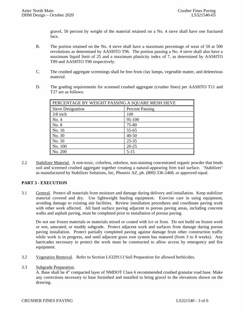
Aztec North Main Crusher Fines Paving DHM Design – October 2020 LS321540-03
CRUSHER FINES PAVING LS321540 - 3 of 6
gravel, 50 percent by weight of the material retained on a No. 4 sieve shall have one fractured face.
B. The portion retained on the No. 4 sieve shall have a maximum percentage of wear of 50 at 500
revolutions as determined by AASHTO T96. The portion passing a No. 4 sieve shall also have a maximum liquid limit of 25 and a maximum plasticity index of 7, as determined by AASHTO T89 and AASHTO T90 respectively.
C. The crushed aggregate screenings shall be free from clay lumps, vegetable matter, and deleterious
material. D. The grading requirements for screened crushed aggregate (crusher fines) per AASHTO T11 and
T27 are as follows:
PERCENTAGE BY WEIGHT PASSING A SQUARE MESH SIEVE Sieve Designation Percent Passing 3/8 inch 100 No. 4 95-100 No. 8 75-80 No. 16 55-65 No. 30 40-50 No. 50 25-35 No. 100 20-25 No. 200 5-15
2.2 Stabilizer Material. A non-toxic, colorless, odorless, non-staining concentrated organic powder that binds
soil and screened crushed aggregate together creating a natural-appearing firm trail surface. ‘Stabilizer’ as manufactured by Stabilizer Solutions, Inc, Phoenix AZ, ph. (800) 336-2468, or approved equal.
PART 3 - EXECUTION 3.1 General. Protect all materials from moisture and damage during delivery and installation. Keep stabilizer
material covered and dry. Use lightweight hauling equipment. Exercise care in using equipment, avoiding damage to existing site facilities. Review installation procedures and coordinate paving work with other work affected. All hard surface paving adjacent to porous paving areas, including concrete walks and asphalt paving, must be completed prior to installation of porous paving.
Do not use frozen materials or materials mixed or coated with ice or frost. Do not build on frozen work or wet, saturated, or muddy subgrade. Protect adjacent work and surfaces from damage during porous paving installation. Protect partially completed paving against damage from other construction traffic while work is in progress, and until adjacent grass root system has matured (from 3 to 8 weeks). Any barricades necessary to protect the work must be constructed to allow access by emergency and fire equipment.
3.2 Vegetative Removal. Refer to Section LS329113 Soil Preparation for allowed herbicides. 3.3 Subgrade Preparation.
A. Base shall be 4” compacted layer of NMDOT Class 6 recommended crushed granular road base. Make any corrections necessary to base furnished and installed to bring gravel to the elevations shown on the drawing.
Aztec North Main Crusher Fines Paving DHM Design – October 2020 LS321540-04
CRUSHER FINES PAVING LS321540 - 4 of 6
B. Pre-soak base material with water and compact to 95% determined by Test Method ASTM D 1557 prior to installing Stabilized Aggregate. Compaction testing to be a minimum of one test per 2,000 square feet of base. City to provide agency for testing. Contractor to schedule with testing agency.
C. Although porous, it is recommended to have proper drainage available to ensure no standing water on surface or adjacent to Stabilized Aggregate, including downspouts when placed under roof overhang and surface drains.
D. Before proceeding with installation, notify City of Aztec Representative in writing of unsuitable site/base conditions.
3.4 Stabilized Crushed Aggregate. Thoroughly pre-blend stabilizer with the screened crushed aggregate at rate as specified by the manufacturer of the stabilizer. It is essential that the stabilizer be mixed thoroughly and uniformly throughout the crusher fines - stabilizer does not act directly on larger aggregate screenings. Blending is best accomplished with a truck-mounted mixer, and a portable mechanical mixer is also acceptable. Blend the stabilizer and the aggregate for a minimum of 15 minutes prior to placing on subgrade or per manufacturer’s recommendations, following all manufacturers’ directions. Spreading the stabilizer over the aggregate and mixing by rototilling is not acceptable and will be rejected. Soil stabilizer shall not be applied prior to, during, or immediately following rainfall. Place the mixed aggregate and stabilizer on the prepared subgrade and rake smooth using a steel fine rake to the desired grade and cross section. Place in lifts of 3 inches maximum thickness per lift. Do not apply deeper than 3 inches in one lift. Refer to plans for depth.
3.5 Watering
A. Water heavily for full-depth moisture penetration of profile. Water activates Stabilizer. Apply 25 to 45 gallons of water per 1-ton to achieve saturation. Randomly test for depth using a probing device, which reaches full depth.
B. Contractor shall wait a minimum of 6 – 72 hours or until such time that the Stabilized Aggregate is able to accept compaction from a 1 to 5 ton roller without separation, plowing or any other physical compromise of the aggregate.
C. If surface aggregate dries significantly quicker than subsurface material, lightly mist surface before compaction.
3.6 Compaction.
A. Compact Stabilized Aggregate to 85% relative compaction by equipment such as; a 2 to 5-ton double drum roller making 3 to 4 passes. Do not begin compaction for 6 hours after placement and up to 72 hours. DO NOT use a vibratory plate compactor or vibration feature on roller, as vibration separates large aggregate particles. If pumping or pancaking of surface occurs, surface is still too wet to roll.
B. Take care in compacting surface when adjacent to planting and irrigation systems, use 8” or 10” hand tamp. Installation of Stabilized Aggregate more than 3” thick shall be installed in lifts. If 4” thick compacted (2) 2” lifts. If 5” thick compacted (2) 2.5” lifts. If Stabilized Aggregate is pre-moistened before installation entire 4” or 5” lift may be installed. Refer to plans for depth. C. Lightly spray surface area following compaction. Do not disturb aggregate surface with spray action.
3.7 Backfilling. Backfill excavation to finished trail edge with scraper spoils using backfill to hold edge of crusher fines in place.
Aztec North Main Crusher Fines Paving DHM Design – October 2020 LS321540-05
CRUSHER FINES PAVING LS321540 - 5 of 6
3.8 Finishing. At completion of surfacing, remove excess spoils from along trail edge and deposit on-site as directed by City of Aztec Representative. Rake trail edges to ensure finished appearance and positive drainage away from trail and into new drainage structures as appropriate, altering grade if necessary.
3.9 Protection
A. Contractor shall furnish and install construction fence around new surface to prevent public access. Fencing shall be maintained in place for a minimum of 12 - 72 hours after completion of installation, or as directed by the City of Aztec Representative. Drying period may take longer due to weather conditions.
B. Contractor shall notify City of Aztec Representative that landscape irrigation shall be restricted near Stabilized Aggregate surface until drying period is complete. Standing water on surface and adjacent to path shall be restricted at all times.
3.10 Maintenance A. Remove debris, such as paper, grass clippings, or organic material by mechanically blowing or hand raking as needed. When plowing snow, use rubber baffle on plow blade or wheels on plow to lift blade 1/4" off the surface.
B. During first year, minor amounts of loose aggregate may appear on surface (1/16 to 1/4"). If material exceeds a ¼”, redistribute over entire surface. Water to 1” depth and compact with power roller of no less than 1000-lbs. Repeat as needed. If cracking occurs, sweep fines into cracks, water thoroughly and hand tamp with an 8” – 10” hand tamp.
3.11 Repairs A. Excavate damaged area to the depth of the Stabilized Aggregate and square off sidewalls. B. If area is dry, moisten damaged portion lightly. C. Pre-blend the dry required amount of Stabilizer® with the proper amount of aggregate in a concrete mixer. D. Add water to the pre-blended Stabilized Aggregate. Thoroughly moisten mix with 25 to 45 gallons per 1-ton of pre-blended material or to approximately 10% moisture content. E. Apply moistened pre-blended Stabilized Aggregate to excavated area to finish grade. F. Compact with an 8” to 10” hand tamp or 250 to 300 pound roller. Keep traffic off areas for 12 to 48 hours after repair has been completed.
3.12 Acceptance. Finished trail surface shall be smooth, uniform, and solid, with no evidence of chipping or cracking. Dried compacted pavement material shall be firm all the way through with no spongy areas. Loose material shall not be present on the surface initially. After the first year of use a minor amount of loose material is expected on the surface. Loose gravel on the surface, or unconsolidated crushed aggregate screenings below the surface, is evidence of improper bonding due to poor mixing or insufficient watering. Test the loose material by wetting, then tamping, and allowing it to dry. Unconsolidated areas shall be dug out and replaced with new screened crushed aggregate meeting these specifications. Patched areas shall be wetted thoroughly and properly compacted. Patching shall be completed prior to any pavement smoothing required. Significant irregularities shall be smoothed out prior to final acceptance of work. Smoothing shall be accomplished by thoroughly rewetting the rough areas and rolling the trail with a heavy roller. Final

Aztec North Main Crusher Fines Paving DHM Design – October 2020 LS321540-06
CRUSHER FINES PAVING LS321540 - 6 of 6
thickness of completed pavement shall not vary more than 1/2 inch from the depth specified on the plans. Measurements may be taken by means of test holes taken at random in the finished trail surface. Correct any variations in the thickness beyond the allowable 1/2 inch variation. Crusher fines shall not vary in top surface depressions/bumps more than ¼ inch in 10 feet measured with a ten foot straight edge. No weed control fabric edges shall be exposed.
END OF SECTION
Aztec North Main Steel Screen Structures DHM Design – October 2020 LS32 31 19 - 1
STEEL SCREEN STRUCTURE LS32 31 19 - 1
SUPPLEMENTAL SPECIFICATIONS
Section No. 520 (Steel Structures) of the New Mexico Standard Specifications for Public Works Construction shall be revised for this project to include and/or substitute the following:
SECTION LS32 31 19
STEEL SHADE STRUCTURE
PART 1 - GENERAL 1.1 SUMMARY
A. Section Includes: This work shall include furnishing all materials, labor, equipment and
miscellaneous items necessary for construction of the weathering steel shade structures. B. Related Sections:
1. New Mexico Standard Specifications for Public Works Construction, January 2019 Edition. 2. New Mexico DOT Standard Specifications, current edition.
1.2 SUBMITTALS
A. Product Data: For each type of product indicated. B. Shop Drawings: Include plans, elevations, sections, details, and attachments to other work. C. Samples: For each screen material and for each color specified. Provide samples 12 inches in
length for linear materials. Provide samples 12 inches square for wire mesh. D. Welding Certificates: Provide welding certificates for certified welders when required.
1.3 QUALITY ASSURANCE A. Installer Qualifications: Fabricator of products. B. Welding Qualifications: Qualify procedures and personnel according to AWS D1.1/D1.1M,
"Structural Welding Code - Steel." C. Mockups: Build mockups to verify selections made under sample submittals and to
demonstrate aesthetic effects and set quality standards for fabrication and installation. Include 3-foot length of screen complying with requirements. Approved mockups may become part of the completed work if undisturbed at time of project completion.
PART 2 – PRODUCTS 2.1 Steel and Iron.
A. Plates, Shapes, and Bars: ASTM A 36/A 36M. B. Bars (Pickets): Hot-rolled, carbon steel complying with ASTM A 29/A 29M, Grade 1010. C. Tubing: ASTM A 500, cold formed steel tubing. D. Bar Grating: NAAMM MBG 531.
E. Bars: Hot-rolled steel strip, ASTM A 1011/A 1011M, Commercial Steel, Type B. F. Wire Rods: ASTM A 510 .
F. Uncoated Steel Sheet: Hot-rolled steel sheet ASTM A 1011/A 1011M, Structural Steel Grade 45. Cold-rolled steel sheet ASTM A 1008/A 1008M, Structural Steel Grade 50.
Aztec North Main Steel Screen Structures DHM Design – October 2020 LS32 31 19 - 2
STEEL SCREEN STRUCTURE LS32 31 19 - 2
2.2 Materials.
A. Posts: Weathering tube steel – see drawings. B. Post Caps: Weathering steel. C. Rails and Frames: Weathering steel tube, steel angle iron, and steel tees. D. Roofing: 4” dia. cedar post. E. Finish: Natural weathered steel with sealant. F. Peacock Sealant for weathering steel or approved equal. Use product with a VOC content of
400 g/L or less when calculated according to 40 CFR 59, Subpart D (EPA Method 24). G. Fastener heads to match deck finish.
PART 3- EXECUTION 3.1 Examination. Examine areas and conditions, with installer present, for compliance with
requirements for site clearing, earthwork, pavement work, construction layout, and other conditions affecting performance of the work. Do not begin installation before final grading is completed unless otherwise permitted by City of Durango Parks Representative. Proceed with installation only after unsatisfactory conditions have been corrected.
3.2 Preparation. Stake locations of screen lines and terminal posts. Indicate locations of utilities,
lawn sprinkler system, underground structures, benchmarks, property monuments when necessary.
3.3 Installation. Space posts uniformly as shown on plans. Install screens by setting posts as
indicated and fastening rails and infill panels to posts. Drill or hand-excavate holes for posts in firm, undisturbed soil. Excavate holes to a depth of not less than 24 inches or as shown on the drawings. Set posts in concrete at indicated spacing. Verify that posts are set plumb, aligned, and at correct height and spacing, and hold in position during setting with concrete or mechanical devices. Place concrete around posts or pipe sleeves and vibrate or tamp for consolidation. Protect above ground portion of posts from concrete splatter. For posts set in sleeves, after posts have been inserted into sleeves, fill annular space between post and sleeve with nonshrink grout, mixed and placed to comply with grout manufacturer's written instructions. Finish top surface of grout to match surrounding grade. For posts set into existing concrete, set posts into holes core drilled not less than 3/4 inch larger than outside diagonal dimension of post and extend posts at least 5 inches into concrete. Clean holes of loose material, insert posts, and fill annular space between post and concrete with nonshrink grout, mixed and placed to comply with grout manufacturer's written instructions. Finish top surface of grout to match surrounding grade.
END OF SECTION
Aztec North Main Soil Preparation DHM Design – October 2020 LS329113-01
SOIL PREPARATION LS32 91 13 - 1
SUPPLEMENTAL SPECIFICATIONS
Section No. 1000 (Landscaping) of the New Mexico Standard Specifications for Public Works Construction shall be revised for this project to include and/or substitute the following:
SECTION LS32 91 13
SOIL PREPARATION
PART 1 - GENERAL
1.1 RELATED DOCUMENTS
A. New Mexico Standard Specifications for Public Works Construction, January 2019 Edition.
1.2 SUMMARY
A. The Work of this Section includes preparation of soil for the purpose of amending the soil for seeding, and tree and shrub bed areas. 1. Soil preparation consists of ripping, fertilizing, soil conditioning and fine grading the
topsoil. Soil preparation as specified herein MUST precede all seeding, and planting.
B. Related Work: 1. Division 01 Section LS01 30 00 Submittals 2. New Mexico Standard Specifications for Public Works Construction, January 2019
Edition Specifications Section 1000. 3. Division 32 Section LS32 92 00 Seeding 4. Division 32 Section LS32 93 00 Planting Trees, Shrubs, and Groundcovers
1.3 SUBMITTALS
A. See Division 01 Section LS01 30 00 Submittals for submittal requirements.
B. Product Data: For each type of product. 1. Include recommendations for application and use. 2. Include test data substantiating that products comply with requirements. 3. Include sieve analyses for aggregate materials. 4. Material Certificates: For each type of soil amendment and fertilizer before delivery to
the site, according to the following: a. Manufacturer's qualified testing agency's certified analysis of standard products.
C. Samples: For each bulk-supplied material, 1-gallon volume of each in sealed containers labeled with content, source, and date obtained. Each Sample shall be typical of the lot of material to be furnished; provide an accurate representation of composition, color, and texture.
D. Quality Control Submittals: 1. Certificates: State, Federal and other inspection certificates shall accompany invoice for
materials showing source or origin. Submit to City of Aztec’s Representative (COAR) prior to acceptance of material.
Aztec North Main Soil Preparation DHM Design – October 2020 LS329113-02
SOIL PREPARATION LS32 91 13 - 2
2. Material Analysis: Provide soil conditioner analysis performed no more than three months prior to delivery to site.
1.4 DELIVERY, STORAGE, AND HANDLING
A. Fertilizer: Deliver inorganic or chemical fertilizer to site in original unopened containers bearing manufacturer’s guaranteed chemical analysis, chemical name, trade name, trademark and conformance to state law, bearing name and warranty of producer.
B. Notify City of Aztec Representative of delivery schedule in advance so material can be inspected upon arrival at project site. Immediately remove unacceptable material from project site.
1.5 PROJECT/SITE CONDITIONS
A. General: Do not perform work when climate and existing site conditions will not provide satisfactory results.
B. Vehicular site access shall be limited to the area(s) indicated on the drawings or as defined by the COAR.
C. Damage to lawns, natural areas, pavements, irrigation systems, underground utilities, and other improvements shall be repaired by the contractor at no additional cost to the City.
1.6 QUALITY ASSURANCE
A. Testing Agency Qualifications: An independent, state-operated, or university-operated
laboratory; experienced in soil science, soil testing, and plant nutrition; with the experience and capability to conduct the testing indicated; and that specializes in types of tests to be performed. 1. Laboratories: Subject to compliance with requirements:
a. Colorado Analytical, Brighton, Colorado 303.659.2313. 2. Multiple Laboratories: At Contractor's option, work may be divided among qualified
testing laboratories specializing in physical testing, chemical testing, and fertility testing.
1.7 PRECONSTRUCTION TESTING A. Preconstruction Testing Service: Engage a qualified testing agency approved by the COAR to
perform preconstruction soil analyses on existing or imported soil.
B. Imported Soil Analyses: For each unamended imported soil source, perform testing on soil samples and furnish soil analysis and a written report containing soil-amendment and fertilizer recommendations by a qualified testing agency performing the testing according to "Soil-Sampling Requirements" and "Testing Requirements" articles. 1. Have testing agency identify and label samples and test reports according to sample
collection and labeling requirements.
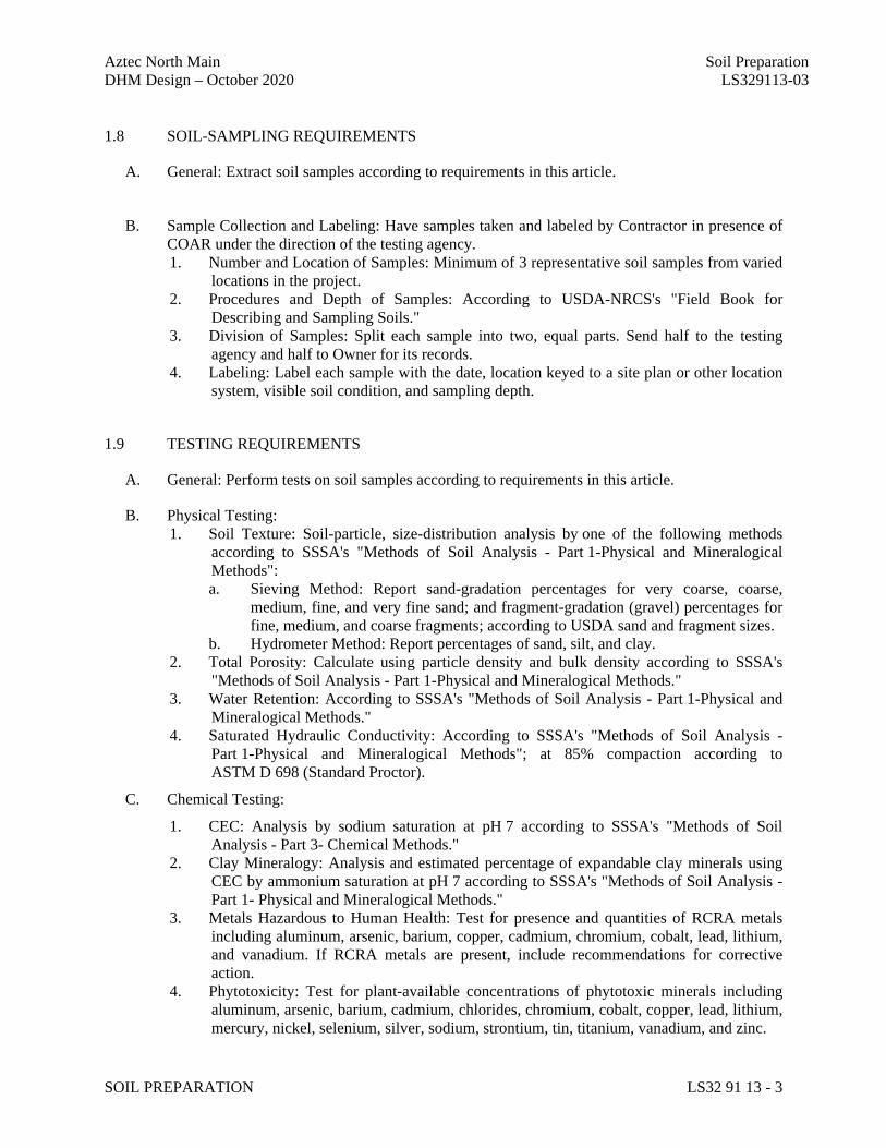
Aztec North Main Soil Preparation DHM Design – October 2020 LS329113-03
SOIL PREPARATION LS32 91 13 - 3
1.8 SOIL-SAMPLING REQUIREMENTS
A. General: Extract soil samples according to requirements in this article.
B. Sample Collection and Labeling: Have samples taken and labeled by Contractor in presence of
COAR under the direction of the testing agency. 1. Number and Location of Samples: Minimum of 3 representative soil samples from varied
locations in the project. 2. Procedures and Depth of Samples: According to USDA-NRCS's "Field Book for
Describing and Sampling Soils." 3. Division of Samples: Split each sample into two, equal parts. Send half to the testing
agency and half to Owner for its records. 4. Labeling: Label each sample with the date, location keyed to a site plan or other location
system, visible soil condition, and sampling depth.
1.9 TESTING REQUIREMENTS
A. General: Perform tests on soil samples according to requirements in this article.
B. Physical Testing: 1. Soil Texture: Soil-particle, size-distribution analysis by one of the following methods
according to SSSA's "Methods of Soil Analysis - Part 1-Physical and Mineralogical Methods": a. Sieving Method: Report sand-gradation percentages for very coarse, coarse,
medium, fine, and very fine sand; and fragment-gradation (gravel) percentages for fine, medium, and coarse fragments; according to USDA sand and fragment sizes.
b. Hydrometer Method: Report percentages of sand, silt, and clay. 2. Total Porosity: Calculate using particle density and bulk density according to SSSA's
"Methods of Soil Analysis - Part 1-Physical and Mineralogical Methods." 3. Water Retention: According to SSSA's "Methods of Soil Analysis - Part 1-Physical and
Mineralogical Methods." 4. Saturated Hydraulic Conductivity: According to SSSA's "Methods of Soil Analysis -
Part 1-Physical and Mineralogical Methods"; at 85% compaction according to ASTM D 698 (Standard Proctor).
C. Chemical Testing:
1. CEC: Analysis by sodium saturation at pH 7 according to SSSA's "Methods of Soil Analysis - Part 3- Chemical Methods."
2. Clay Mineralogy: Analysis and estimated percentage of expandable clay minerals using CEC by ammonium saturation at pH 7 according to SSSA's "Methods of Soil Analysis - Part 1- Physical and Mineralogical Methods."
3. Metals Hazardous to Human Health: Test for presence and quantities of RCRA metals including aluminum, arsenic, barium, copper, cadmium, chromium, cobalt, lead, lithium, and vanadium. If RCRA metals are present, include recommendations for corrective action.
4. Phytotoxicity: Test for plant-available concentrations of phytotoxic minerals including aluminum, arsenic, barium, cadmium, chlorides, chromium, cobalt, copper, lead, lithium, mercury, nickel, selenium, silver, sodium, strontium, tin, titanium, vanadium, and zinc.
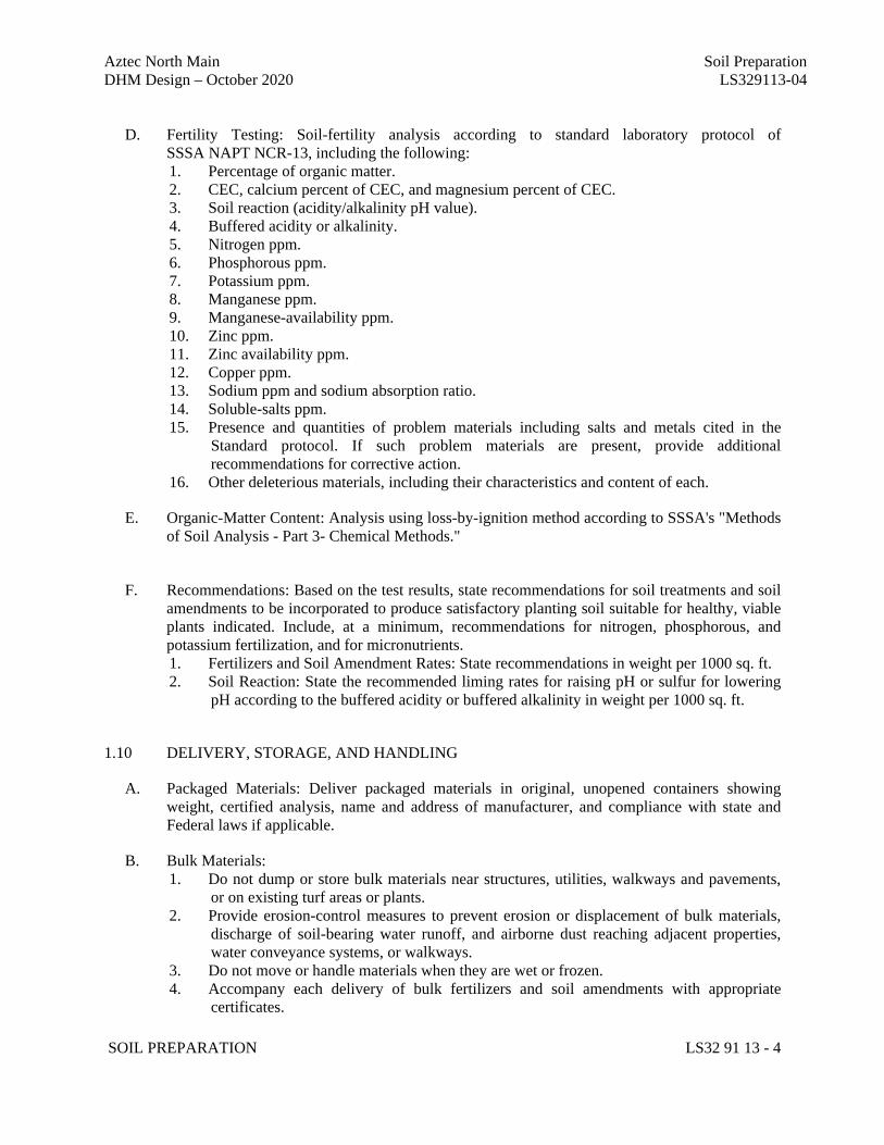
Aztec North Main Soil Preparation DHM Design – October 2020 LS329113-04
SOIL PREPARATION LS32 91 13 - 4
D. Fertility Testing: Soil-fertility analysis according to standard laboratory protocol of
SSSA NAPT NCR-13, including the following: 1. Percentage of organic matter. 2. CEC, calcium percent of CEC, and magnesium percent of CEC. 3. Soil reaction (acidity/alkalinity pH value). 4. Buffered acidity or alkalinity. 5. Nitrogen ppm. 6. Phosphorous ppm. 7. Potassium ppm. 8. Manganese ppm. 9. Manganese-availability ppm. 10. Zinc ppm. 11. Zinc availability ppm. 12. Copper ppm. 13. Sodium ppm and sodium absorption ratio. 14. Soluble-salts ppm. 15. Presence and quantities of problem materials including salts and metals cited in the
Standard protocol. If such problem materials are present, provide additional recommendations for corrective action.
16. Other deleterious materials, including their characteristics and content of each.
E. Organic-Matter Content: Analysis using loss-by-ignition method according to SSSA's "Methods of Soil Analysis - Part 3- Chemical Methods."
F. Recommendations: Based on the test results, state recommendations for soil treatments and soil
amendments to be incorporated to produce satisfactory planting soil suitable for healthy, viable plants indicated. Include, at a minimum, recommendations for nitrogen, phosphorous, and potassium fertilization, and for micronutrients. 1. Fertilizers and Soil Amendment Rates: State recommendations in weight per 1000 sq. ft. 2. Soil Reaction: State the recommended liming rates for raising pH or sulfur for lowering
pH according to the buffered acidity or buffered alkalinity in weight per 1000 sq. ft.
1.10 DELIVERY, STORAGE, AND HANDLING
A. Packaged Materials: Deliver packaged materials in original, unopened containers showing weight, certified analysis, name and address of manufacturer, and compliance with state and Federal laws if applicable.
B. Bulk Materials: 1. Do not dump or store bulk materials near structures, utilities, walkways and pavements,
or on existing turf areas or plants. 2. Provide erosion-control measures to prevent erosion or displacement of bulk materials,
discharge of soil-bearing water runoff, and airborne dust reaching adjacent properties, water conveyance systems, or walkways.
3. Do not move or handle materials when they are wet or frozen. 4. Accompany each delivery of bulk fertilizers and soil amendments with appropriate
certificates.
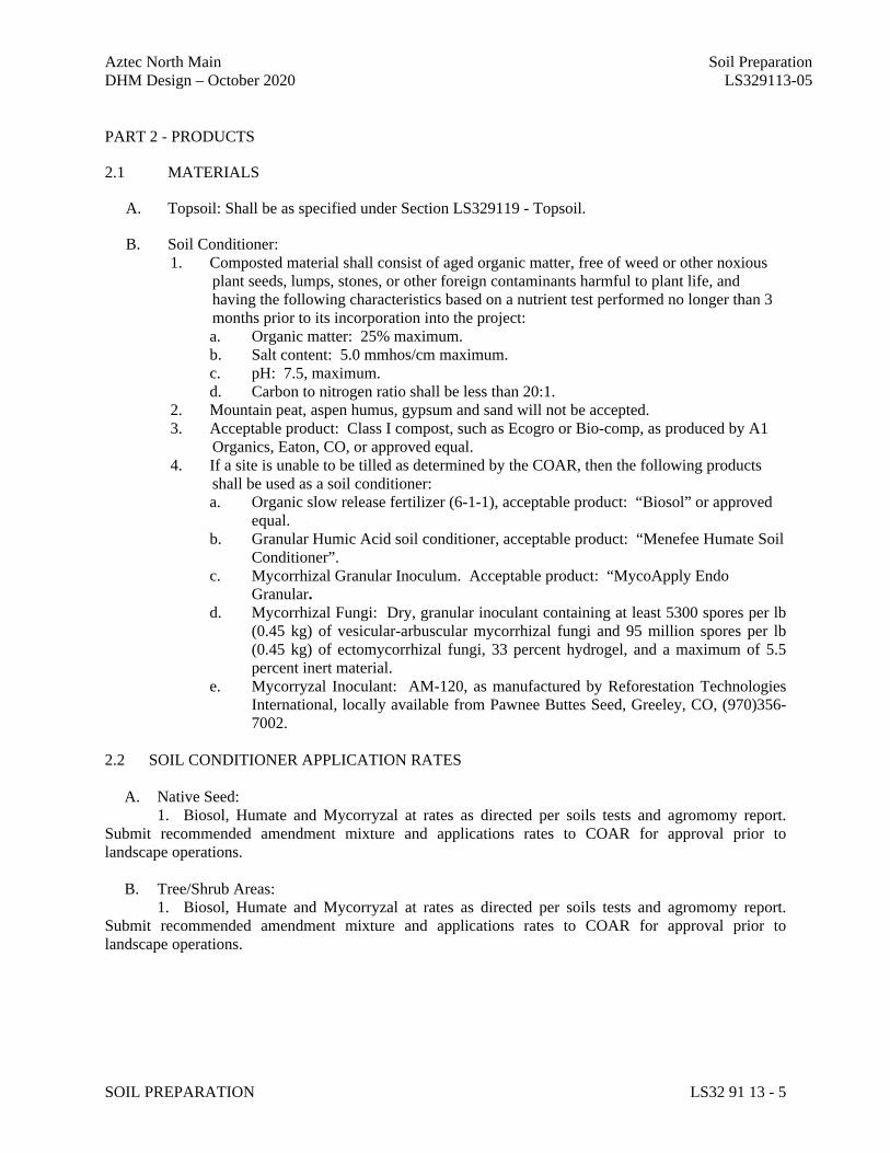
Aztec North Main Soil Preparation DHM Design – October 2020 LS329113-05
SOIL PREPARATION LS32 91 13 - 5
PART 2 - PRODUCTS
2.1 MATERIALS
A. Topsoil: Shall be as specified under Section LS329119 - Topsoil.
B. Soil Conditioner: 1. Composted material shall consist of aged organic matter, free of weed or other noxious
plant seeds, lumps, stones, or other foreign contaminants harmful to plant life, and having the following characteristics based on a nutrient test performed no longer than 3 months prior to its incorporation into the project: a. Organic matter: 25% maximum. b. Salt content: 5.0 mmhos/cm maximum. c. pH: 7.5, maximum. d. Carbon to nitrogen ratio shall be less than 20:1.
2. Mountain peat, aspen humus, gypsum and sand will not be accepted. 3. Acceptable product: Class I compost, such as Ecogro or Bio-comp, as produced by A1
Organics, Eaton, CO, or approved equal. 4. If a site is unable to be tilled as determined by the COAR, then the following products
shall be used as a soil conditioner: a. Organic slow release fertilizer (6-1-1), acceptable product: “Biosol” or approved
equal. b. Granular Humic Acid soil conditioner, acceptable product: “Menefee Humate Soil
Conditioner”. c. Mycorrhizal Granular Inoculum. Acceptable product: “MycoApply Endo
Granular. d. Mycorrhizal Fungi: Dry, granular inoculant containing at least 5300 spores per lb
(0.45 kg) of vesicular-arbuscular mycorrhizal fungi and 95 million spores per lb (0.45 kg) of ectomycorrhizal fungi, 33 percent hydrogel, and a maximum of 5.5 percent inert material.
e. Mycorryzal Inoculant: AM-120, as manufactured by Reforestation Technologies International, locally available from Pawnee Buttes Seed, Greeley, CO, (970)356-7002.
2.2 SOIL CONDITIONER APPLICATION RATES A. Native Seed: 1. Biosol, Humate and Mycorryzal at rates as directed per soils tests and agromomy report. Submit recommended amendment mixture and applications rates to COAR for approval prior to landscape operations. B. Tree/Shrub Areas: 1. Biosol, Humate and Mycorryzal at rates as directed per soils tests and agromomy report. Submit recommended amendment mixture and applications rates to COAR for approval prior to landscape operations.
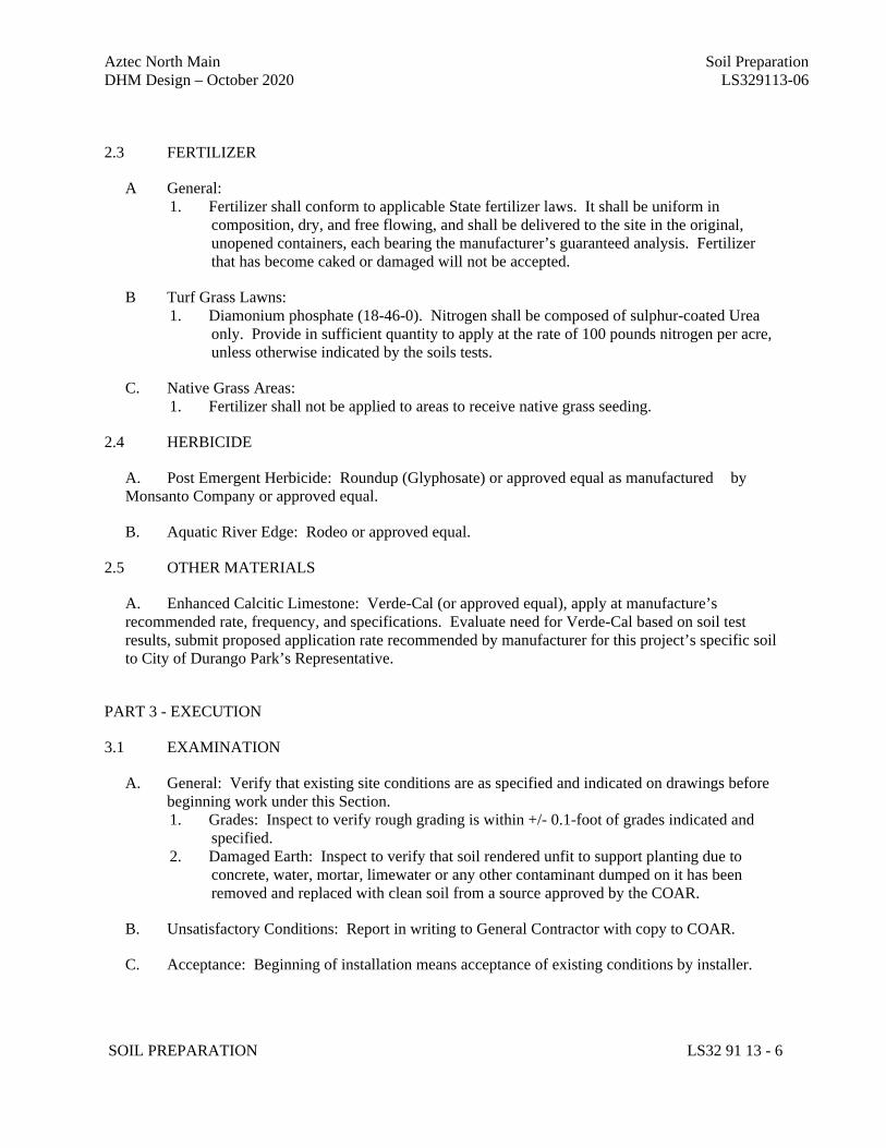
Aztec North Main Soil Preparation DHM Design – October 2020 LS329113-06
SOIL PREPARATION LS32 91 13 - 6
2.3 FERTILIZER
A General: 1. Fertilizer shall conform to applicable State fertilizer laws. It shall be uniform in
composition, dry, and free flowing, and shall be delivered to the site in the original, unopened containers, each bearing the manufacturer’s guaranteed analysis. Fertilizer that has become caked or damaged will not be accepted.
B Turf Grass Lawns: 1. Diamonium phosphate (18-46-0). Nitrogen shall be composed of sulphur-coated Urea
only. Provide in sufficient quantity to apply at the rate of 100 pounds nitrogen per acre, unless otherwise indicated by the soils tests.
C. Native Grass Areas: 1. Fertilizer shall not be applied to areas to receive native grass seeding.
2.4 HERBICIDE
A. Post Emergent Herbicide: Roundup (Glyphosate) or approved equal as manufactured by Monsanto Company or approved equal.
B. Aquatic River Edge: Rodeo or approved equal.
2.5 OTHER MATERIALS
A. Enhanced Calcitic Limestone: Verde-Cal (or approved equal), apply at manufacture’s recommended rate, frequency, and specifications. Evaluate need for Verde-Cal based on soil test results, submit proposed application rate recommended by manufacturer for this project’s specific soil to City of Durango Park’s Representative.
PART 3 - EXECUTION
3.1 EXAMINATION
A. General: Verify that existing site conditions are as specified and indicated on drawings before beginning work under this Section. 1. Grades: Inspect to verify rough grading is within +/- 0.1-foot of grades indicated and
specified. 2. Damaged Earth: Inspect to verify that soil rendered unfit to support planting due to
concrete, water, mortar, limewater or any other contaminant dumped on it has been removed and replaced with clean soil from a source approved by the COAR.
B. Unsatisfactory Conditions: Report in writing to General Contractor with copy to COAR.
C. Acceptance: Beginning of installation means acceptance of existing conditions by installer.
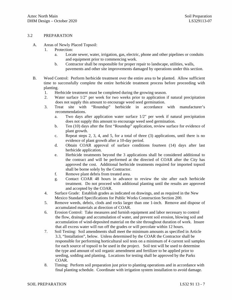
Aztec North Main Soil Preparation DHM Design – October 2020 LS329113-07
SOIL PREPARATION LS32 91 13 - 7
3.2 PREPARATION
A. Areas of Newly Placed Topsoil: 1. Protection:
a. Locate sewer, water, irrigation, gas, electric, phone and other pipelines or conduits and equipment prior to commencing work.
b. Contractor shall be responsible for proper repair to landscape, utilities, walls, pavements and other site improvements damaged by operations under this section.
B. Weed Control: Perform herbicide treatment over the entire area to be planted. Allow sufficient time to successfully complete the entire herbicide treatment process before proceeding with planting. 1. Herbicide treatment must be completed during the growing season. 2. Water surface 1/2" per week for two weeks prior to application if natural precipitation
does not supply this amount to encourage weed seed germination. 3. Treat site with “Roundup” herbicide in accordance with manufacturer’s
recommendations. a. Two days after application water surface 1/2" per week if natural precipitation
does not supply this amount to encourage weed seed germination. b. Ten (10) days after the first “Roundup” application, review surface for evidence of
plant growth. c. Repeat steps 2, 3, 4, and 5, for a total of three (3) applications, until there is no
evidence of plant growth after a 10-day period. d. Obtain COAR approval of surface conditions fourteen (14) days after last
herbicide application. e. Herbicide treatments beyond the 3 applications shall be considered additional to
the contract and will be performed at the directed of COAR after the City has approved the cost. Additional herbicide treatments required for imported topsoil shall be borne solely by the Contractor.
f. Remove plant debris from treated area. g. Contact COAR 48 hours in advance to review the site after each herbicide
treatment. Do not proceed with additional planting until the results are approved and accepted by the COAR.
4. Surface Grade: Establish grades as indicated on drawings, and as required in the New Mexico Standard Specifications for Public Works Construction Section 200.
5. Remove weeds, debris, clods and rocks larger than one 1-inch. Remove and dispose of accumulated materials at direction of COAR.
6. Erosion Control: Take measures and furnish equipment and labor necessary to control the flow, drainage and accumulation of water, and prevent soil erosion, blowing soil and accumulation of wind-deposited material on the site throughout duration of work. Insure that all excess water will run off the grades or will percolate within 12 hours.
7. Soil Testing: Soil amendments shall meet the minimum amounts as specified in Article 3.3, “Installation”, below. Unless determined by the COAR the Contractor shall be responsible for performing horticultural soil tests on a minimum of 4 current soil samples for each source of topsoil to be used in the project. Soil test will be used to determine the type and amount of soil organic amendment and fertilizer to be applied prior to seeding, sodding and planting. Locations for testing shall be approved by the Parks COAR.
8. Timing: Perform soil preparation just prior to planting operations and in accordance with final planting schedule. Coordinate with irrigation system installation to avoid damage.
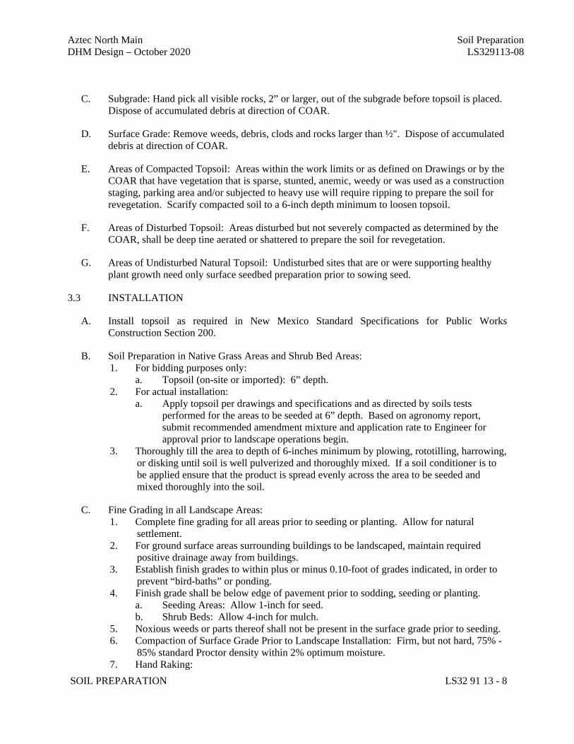
Aztec North Main Soil Preparation DHM Design – October 2020 LS329113-08
SOIL PREPARATION LS32 91 13 - 8
C. Subgrade: Hand pick all visible rocks, 2” or larger, out of the subgrade before topsoil is placed. Dispose of accumulated debris at direction of COAR.
D. Surface Grade: Remove weeds, debris, clods and rocks larger than ½". Dispose of accumulated debris at direction of COAR.
E. Areas of Compacted Topsoil: Areas within the work limits or as defined on Drawings or by the COAR that have vegetation that is sparse, stunted, anemic, weedy or was used as a construction staging, parking area and/or subjected to heavy use will require ripping to prepare the soil for revegetation. Scarify compacted soil to a 6-inch depth minimum to loosen topsoil.
F. Areas of Disturbed Topsoil: Areas disturbed but not severely compacted as determined by the COAR, shall be deep tine aerated or shattered to prepare the soil for revegetation.
G. Areas of Undisturbed Natural Topsoil: Undisturbed sites that are or were supporting healthy plant growth need only surface seedbed preparation prior to sowing seed.
3.3 INSTALLATION
A. Install topsoil as required in New Mexico Standard Specifications for Public Works Construction Section 200.
B. Soil Preparation in Native Grass Areas and Shrub Bed Areas: 1. For bidding purposes only:
a. Topsoil (on-site or imported): 6” depth. 2. For actual installation:
a. Apply topsoil per drawings and specifications and as directed by soils tests performed for the areas to be seeded at 6” depth. Based on agronomy report, submit recommended amendment mixture and application rate to Engineer for approval prior to landscape operations begin.
3. Thoroughly till the area to depth of 6-inches minimum by plowing, rototilling, harrowing, or disking until soil is well pulverized and thoroughly mixed. If a soil conditioner is to be applied ensure that the product is spread evenly across the area to be seeded and mixed thoroughly into the soil.
C. Fine Grading in all Landscape Areas: 1. Complete fine grading for all areas prior to seeding or planting. Allow for natural
settlement. 2. For ground surface areas surrounding buildings to be landscaped, maintain required
positive drainage away from buildings. 3. Establish finish grades to within plus or minus 0.10-foot of grades indicated, in order to
prevent “bird-baths” or ponding. 4. Finish grade shall be below edge of pavement prior to sodding, seeding or planting.
a. Seeding Areas: Allow 1-inch for seed. b. Shrub Beds: Allow 4-inch for mulch.
5. Noxious weeds or parts thereof shall not be present in the surface grade prior to seeding. 6. Compaction of Surface Grade Prior to Landscape Installation: Firm, but not hard, 75% -
85% standard Proctor density within 2% optimum moisture. 7. Hand Raking:
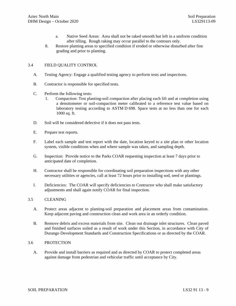
Aztec North Main Soil Preparation DHM Design – October 2020 LS329113-09
SOIL PREPARATION LS32 91 13 - 9
a. Native Seed Areas: Area shall not be raked smooth but left in a uniform condition after tilling. Rough raking may occur parallel to the contours only.
8. Restore planting areas to specified condition if eroded or otherwise disturbed after fine grading and prior to planting.
3.4 FIELD QUALITY CONTROL
A. Testing Agency: Engage a qualified testing agency to perform tests and inspections.
B. Contractor is responsible for specified tests.
C. Perform the following tests: 1. Compaction: Test planting-soil compaction after placing each lift and at completion using
a densitometer or soil-compaction meter calibrated to a reference test value based on laboratory testing according to ASTM D 698. Space tests at no less than one for each 1000 sq. ft.
D. Soil will be considered defective if it does not pass tests.
E. Prepare test reports.
F. Label each sample and test report with the date, location keyed to a site plan or other location system, visible conditions when and where sample was taken, and sampling depth.
G. Inspection: Provide notice to the Parks COAR requesting inspection at least 7 days prior to anticipated date of completion.
H. Contractor shall be responsible for coordinating soil preparation inspections with any other necessary utilities or agencies, call at least 72 hours prior to installing sod, seed or plantings.
I. Deficiencies: The COAR will specify deficiencies to Contractor who shall make satisfactory adjustments and shall again notify COAR for final inspection.
3.5 CLEANING
A. Protect areas adjacent to planting-soil preparation and placement areas from contamination. Keep adjacent paving and construction clean and work area in an orderly condition.
B. Remove debris and excess materials from site. Clean out drainage inlet structures. Clean paved and finished surfaces soiled as a result of work under this Section, in accordance with City of Durango Development Standards and Construction Specifications or as directed by the COAR.
3.6 PROTECTION
A. Provide and install barriers as required and as directed by COAR to protect completed areas against damage from pedestrian and vehicular traffic until acceptance by City.
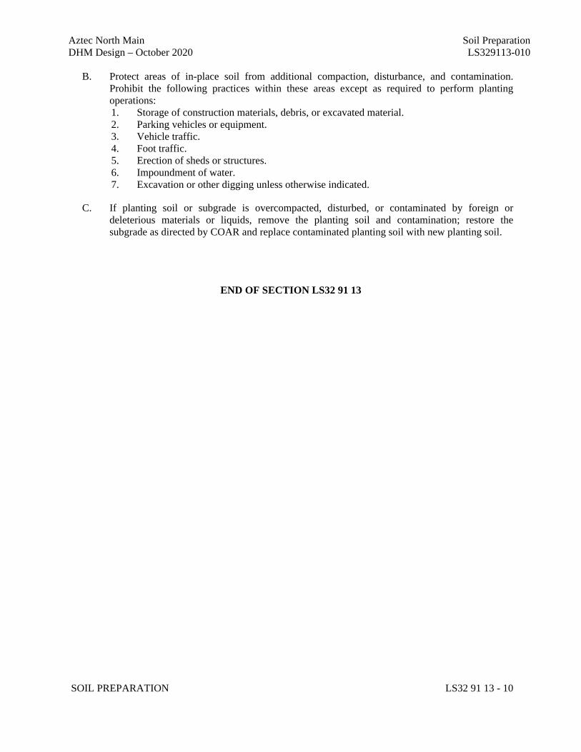
Aztec North Main Soil Preparation DHM Design – October 2020 LS329113-010
SOIL PREPARATION LS32 91 13 - 10
B. Protect areas of in-place soil from additional compaction, disturbance, and contamination. Prohibit the following practices within these areas except as required to perform planting operations: 1. Storage of construction materials, debris, or excavated material. 2. Parking vehicles or equipment. 3. Vehicle traffic. 4. Foot traffic. 5. Erection of sheds or structures. 6. Impoundment of water. 7. Excavation or other digging unless otherwise indicated.
C. If planting soil or subgrade is overcompacted, disturbed, or contaminated by foreign or deleterious materials or liquids, remove the planting soil and contamination; restore the subgrade as directed by COAR and replace contaminated planting soil with new planting soil.
END OF SECTION LS32 91 13
Aztec North Main Topsoil DHM Design – October 2020 LS329119-01
TOPSOIL LS32119-01
SUPPLEMENTAL SPECIFICATIONS
Section No. 1000 (Landscaping) of the New Mexico Standard Specifications for Public Works Construction shall be revised for this project to include and/or substitute the following:
SECTION LS32 91 19
TOPSOIL
PART 1 – GENERAL 1.1 SUMMARY A. Section Includes: This work shall consist of importing suitable topsoil from stockpiles, or
approved pits. It shall include the placing of topsoil after construction and grading operations are completed. All work shall be done in accordance with these specifications and in reasonably close conformity with the lines and thicknesses shown on the plans or as directed.
B. Related Sections/Documents:
1. Division 01 Section LS01 30 00 Submittals 2. New Mexico Standard Specifications for Public Works Construction, January 2019
Edition PART 2 - MATERIALS 2.1 Topsoil. Topsoil may be salvaged from within the construction limits, or imported from an approved
source. All topsoil must meet requirements in this section. Topsoil shall consist of loose friable loam reasonably free of admixtures of subsoil, refuse, stumps, roots, rocks, brush, weeds, heavy clay, hard clods, toxic substances, construction debris or other material which would be detrimental to the proper development of vegetative growth. The City of Aztec Representative reserves the right to reject any topsoil deemed unsuitable upon the sole discretion of the City of Aztec Representative. Topsoil shall be screened to ½” minus.
Imported Topsoil: All topsoil shall be a loam or sandy loam. At least 10 days prior to topsoil delivery, notify Project Manager of the source(s) form which topsoil is to be furnished. Topsoil shall be furnished by the Contractor and shall be a natural, friable soil representative of productive soils in the vicinity. It shall be obtained from the top 12" of well drained areas.
All topsoil must meet requirements in this section. Topsoil shall consist of loose friable loam reasonably free of admixtures of subsoil, refuse, stumps, roots, rocks, brush, weeds, heavy clay, hard clods, toxic substances, construction debris or other material which would be detrimental to the proper development of vegetative growth. The City of Aztec Representative reserves the right to reject any topsoil deemed unsuitable upon the sole discretion of the City of Aztec Representative. Also see Section 2.2 Soil Test.
Fertile, friable, loamy soil, free from subsoil, refuse, roots, heavy or stiff clay, stones larger than 1/2 inch, coarse sand, noxious seeds, sticks, brush, litter, and other deleterious substances; suitable for the germination of seeds and the support of vegetative growth. The pH value shall be between 7.0 and 8.0.

Aztec North Main Topsoil DHM Design – October 2020 LS329119-02
TOPSOIL LS32119-02
Soil Texture: Sand, 30 to 50 percent; silt, 30 to 50 percent; clay, 5 to 30 percent.
Additives: As determined by soil fertility tests. Fineness Modulus: Greater than 1.7
% Organic Content: 5.0% minimum.
Source: The Contractor shall provide the following information: 1. Specific locations of property from which the topsoil is to be stripped. If obtained from a commercial supplier, the same is applicable. 2. Name and address of present Owner of property. 3. Laboratory Soil test results. Topsoil shall meet the following mechanical analysis: Passing % Retaining % 3/4-inch screen 100 0 - 0 1/2-inch screen 97 – 100 0 - 3 No. 100 mesh sieve 60 – 40 0 - 60 Submit sample for approval prior to delivery to job site.
2.2 Soil Test. See Section LS329113 Soil Preparation for Soil Testing information. The Contractor shall
take soil tests at (3) locations of the existing on-site soils and imported topsoil to determine the proper fertilizer and trace elements that are to be added to the soil, and their application rates. Soil samples shall be sent to the laboratory listed in section LS329113 for native seeding or athletic turf analysis as appropriate. For imported topsoil, submit soil test results for source soil; tests must have been done within the previous year. A copy of the soil test results shall be provided to the City of Aztec Representative, and the City of Aztec Representative shall approve the fertilizer and trace elements and their respective application rates after review of the soil testing recommendations. Soil texture shall be included in the soil tests.
PART 3 - EXECUTION 3.1 Topsoiling. All excess suitable topsoil shall remain the property of the Owner, and shall be stockpiled at
a site as designated by the City of Aztec Representative. All unsuitable topsoil as determined by the City of Aztec Representative shall be removed and legally disposed of off-site at the expense of the Contractor.
Topsoil shall not be placed until the areas to be covered have been properly prepared and grading operations and all other construction activity in the area have been completed. Topsoil shall be placed and spread in all areas of construction disturbance at a minimum depth of 6 inches or as specified on the drawings. Topsoil shall be keyed to the underlying material by the use of harrows, rollers, or other equipment suitable for the purpose. Variations shall not be more than 0.08 ft.. Remove all debris subject to termite attack, rot or corrosion, and all other deleterious materials from areas to be filled. All loose exposed rock larger than 1/2" in turf areas and 3” in dryland areas shall be removed.
3.2 Soil Amendments. Additional trace elements at a rate of 100 to 250 pounds per acre, as required by the

Aztec North Main Topsoil DHM Design – October 2020 LS329119-03
TOPSOIL LS32119-03
soil tests, shall be thoroughly mixed with the fertilizer. Fertilizer and trace elements shall be thoroughly incorporated into the topsoil at the application rates approved by the City of Aztec Representative from the soil testing recommendations.
Organic Soil Amendment (A-1 Organics Premium 3 or approved equal) for turf areas shall be added at a
rate of 4cy/1,000 sf and for native areas shall be added at a rate of 1cy/1,000 sf or as recommended by the soil tests. Provide soil analysis for amendment for review/approval by City of Aztec Representative.
3.3 Fine Grading. Fine grading by hand or other means as approved by the City of Aztec Representative
shall be required after topsoil placement to provide a reasonably smooth surface free from irregularities and visual undulations. The finished grade shall be brought to the elevations indicated and sloped to drain water away from structures and provide positive drainage for surface water runoff. Finished surfaces shall be smooth and even and satisfactory to the City of Aztec Representative. After fine grading the surface shall not vary more than 0.04 ft. in 10 ft. from the proposed profile and cross-section, or more than 0.04 from the proposed elevation. Surface debris from fine grading operations shall be removed from the site and disposed of legally off-site at the expense of the Contractor.
END OF SECTION
Aztec North Main Seeding Turf and Grasses DHM Design – October 2020 LS329200-01
SEEDING TURF AND GRASSES LS329200-01
SUPPLEMENTAL SPECIFICATIONS
Section No. 1000 (Landscaping) of the New Mexico Standard Specifications for Public Works Construction shall be revised for this project to include and/or substitute the following:
SECTION LS32 92 00
SEEDING GRASSES
PART 1 - GENERAL 1.1 SUMMARY A. Section Includes: Work to be performed under this section shall include all labor, equipment,
materials, and miscellaneous items necessary to perform all seed bed preparation, seeding, raking, mulching and crimping areas of construction disturbance as shown on the drawings or as required by the specifications.
B. Related Sections:
1. Division 32 Section LS32 91 19 Topsoil 2. Division 32 Section LS32 93 00 Planting Trees, Shrubs, and Groundcovers
1.2 REFERENCE STANDARDS
A. New Mexico Standard Specifications for Public Works Construction, January 2019 Edition Specifications Section 1000.
B. New Mexico Seed Law (NMSA 1978, § 76-10-11 et seq.) PART 2 - MATERIALS 2.1 Non-selective Herbicide: 'Roundup' non-selective herbicide, as manufactured by Scotts Company, or
approved equal, shall be delivered to the site, unopened in original containers, each bearing the manufacturer's label, and in conformance with state and federal pesticide laws and regulations. Roundup should not be used near drainages or wetlands. For areas in drainages or wetlands an herbicide approved by the EPA and properly labeled for this use shall be used.
2.2 Seed. All seed shall be furnished in sealed bags or containers showing the name and address of the
supplier, the seed name, the lot number, net weight, the percent of weed seed content, and the guaranteed percentage of purity and germination. All seed furnished shall be free from noxious weeds such as Russian or Canadian Thistle, European Bindweed, Johnson Grass, Leafy Spurge, and Poa Annua. Verification shall be given as to the point of origin for each kind of seed accepted. The Contractor shall furnish a signed statement certifying that the seed furnished is from a lot that has been tested by a recognized laboratory for seed testing within six months prior to the date of delivery.
Seed and seed labels shall conform to all current state and federal regulations and will be subject to the testing provisions of the Association of Official Seed Analysis. Seed shall have a minimum purity of 95% and a minimum germination of 85% for a minimum pure live seed (PLS) rate of 80%. Seed shall
Aztec North Main Seeding Turf and Grasses DHM Design – October 2020 LS329200-02
SEEDING TURF AND GRASSES LS329200-02
have a maximum weed seed content of 0.05%.
A. Seed Mix. Seed mix shall be as specified on the plans. The Contractor shall furnish a letter of certification from the seed supplier specifying the seed mix and test results prior to seeding for approval of the seed mix by the City of Aztec Representative.
2.4 Straw Mulch (if used). Straw Mulch shall consist of straw from native grasses grown in fields certified to
be free of weeds, and should not contain seed of noxious weeds. Straw in such an advanced stages of decomposition as to smother or retard the normal growth of grass will not be accepted. Old dry straw, which breaks in the crimping process in lieu of bending will not be accepted.
2.5 Hydromulch. Mulch for hydromulching shall be Weyerhaeuser "Silva Fiber" or approved equal. Wood
cellulose fiber for hydraulic mulching shall not contain any substance or factor which might inhibit germination or growth of grass seed. It shall be dyed an appropriate color to allow metering of its application. The wood cellulose fibers shall have the property of becoming evenly dispersed and suspended when agitated in water. When sprayed uniformly on the surface of the soil, the fibers shall form a blotter-like groundcover which readily absorbs water, and allows infiltration to the underlying soil. Weight specifications from suppliers, and for all applications, shall refer only to air dry weight of the fiber, a standard equivalent to 10% moisture. The mulch material shall be supplied in packages marked by the manufacture to show the air dry weight content. Suppliers shall certify that their product meets all of the foregoing requirements pertaining to wood cellulose fiber mulch.
2.6 Tackifier. ‘M-Binder’ tackifier applied at a rate of 80-100 lbs./acre shall be used for hydromulched areas.
‘Plantago’ tackifier applied at a rate of 50-100 lbs./acre shall be used for straw mulched areas. Applications shall be per manufacturer’s instructions.
2.7 Erosion Control Fabric. ‘Excel S-2 All Natural’ double net excelsior blanket, as manufactured by
Western Excelsior Corp., or approved equal. The excelsior blanket shall consist of a uniform 10mm thick machine-made mat of curled wood excelsior with 80% of the fibers 6" or longer in length. The top and bottom of each blanket shall be covered with a biodegradable cotton netting with a maximum 1/2" x 1/2" opening size. No plastic netting will be permitted.
2.8 Staples or Pins for Erosion Control Fabric. Pins and staples shall be made of wire .1205" (11 gauge) or
larger in diameter. "U" shaped staples shall have legs 6" long and 1" crown. "T" shaped pins shall have a minimum length of 8" after bending. The bar of the "T" shall be at least 4" long with the single wire end bent downward approximately 3/4".
PART 3 - EXECUTION 3.1 General. The Contractor shall be responsible for the cost of replacement of any irrigation system
components that are damaged as a result of his work. The Owner shall be responsible for watering. In addition, the Contractor shall be responsible for the daily clean-up necessitated by his operations. This shall include, but is not limited to, the cleaning of sidewalks, stairs, roads, parking lots, and other physical objects if necessary. The Contractor shall be especially careful to avoid the over spray of hydromulch on adjacent plant material or the staining of sidewalks. The Contractor shall be responsible for any damage caused by his operations.
The Contractor shall notify the City of Aztec Representative at least 24 hours in advance of the
commencement of seeding, and the City of Aztec Representative shall verify the seed quantities prior to
Aztec North Main Seeding Turf and Grasses DHM Design – October 2020 LS329200-03
SEEDING TURF AND GRASSES LS329200-03
their application. 3.2 Removal of Existing Weeds and Undesirable Vegetation. ‘Roundup’ should not be used near drainages
or wetlands. For areas in drainages or wetlands an herbicide approved by the EPA and properly labeled for this use shall be used. Other areas to be seeded having existing weeds and other undesirable vegetation including annual grasses shall be treated with 'Roundup' herbicide as directed by the manufacturer, and in conformance with state and federal pesticide laws and regulations. Herbicide shall be applied with equipment as recommended by the manufacturer, under the supervision of a commercial pesticide applicator certified in the State of New Mexico. The Contractor shall furnish a copy of the applicator's certification to the City of Aztec Representative prior to commencing this work. 'Roundup' shall be applied as a 2% spray solution to existing weeds and grasses. Avoid application when daytime temperatures are 80 degrees F or above, or if rain is expected within 24 hours. No spraying shall be done when the wind is 5 mph or greater. Applications should be made on a spray to wet basis. Spray coverage should be uniform and complete. Do not spray to point of runoff. Care shall be taken to protect existing trees and shrubs. If rainfall occurs within 6 hours of the application of 'Roundup', the Contractor shall reapply at his own expense.
Mechanical weed removal is also permitted provided that the methods of mechanical weed removal are
acceptable to and approved by the City of Aztec Representative. 3.3 Soil Preparation. All areas to be seeded shall first be topsoiled in accordance with Section LS32 91 19.
Topsoil shall be backfilled to a minimum depth of 6" or as shown on the drawings. The surface of areas that have been previously prepped or seeded shall be scarified by hand raking or other means. A reasonably even, loose seed bed, free of weeds, construction debris and other foreign matter shall be established. Fine grade all areas to eliminate visible surface undulations, rounding the tops and bottoms of all slopes and provide positive drainage for all potential surface water runoff. All sticks, stones and other debris greater than 1/2" in any dimension shall be carefully removed. The entire surface shall then be carefully graded so that no unevenness appears. The fine grading shall be approved by the City of Aztec Representative prior to the application of fertilizer and seed.
3.4 Seeding. In no case shall seed be installed within 7 days of spraying of 'Roundup'. Seed shall be
uniformly applied over the entire area. In areas where the slope is 3:1 or flatter, seeding will be done with a seed drill, "Brillion" seeder, overseeder if appropriate, or other equipment as approved by the City of Aztec Representative. The equipment shall be operated in a direction generally perpendicular to the direction of the slope. Drill seed 1/2 inch deep with rows spaced no more than 7 inches apart.
On all slopes steeper than 3:1, or when broadcast seeding is approved by the City of Aztec Representative, seed shall be applied by means of mechanical broadcaster or hydroseeder at double the rate required for drill seeding specified above. All seed sown by mechanical broadcasters shall be raked or dragged into the soil to a depth of 1/2". Care shall be taken to insure uniform coverage of seed.
A. Native Seeding. Native seed mix shall be drilled at the rate of 25 lbs. pure live seed (PLS) per
acre (.57 lb. pure live seed (PLS) per 1000 sq. ft.) or as specified in the drawings. Seeding in non-irrigated areas shall be restricted according to the following schedule:
1. Below 6000' elevation: Spring seeding shall occur between spring thaw to May 1st. Fall
seeding shall occur between August 1st until consistent ground freeze.
Aztec North Main Seeding Turf and Grasses DHM Design – October 2020 LS329200-04
SEEDING TURF AND GRASSES LS329200-04
3.6 Straw Mulching. Native grass straw mulch, when permitted by the City of Aztec Representative, shall be applied at the rate of two tons per acre (approximately 2 bales per 1000 sq. ft.). It shall be uniformly crimped in with a crimper or other approved method to a minimum depth of 3". The seeded areas shall be mulched and crimped within 24 hours after seeding. Seeding areas that have been disturbed prior to or during mulching operations shall be re-seeded at the Contractor's expense. Areas not properly mulched or damaged shall be repaired or re-mulched in an acceptable manner. Mulching operations shall not take place during windy conditions.
3.7 Hydromulching. Hydraulic mulching equipment shall include a pump capable of being operated at 100
gallons per minute and 100 pounds per square inch pressure, unless otherwise directed. The equipment shall have an acceptable pressure gauge and nozzle adaptable to hydraulic seeding requirements. Storage tanks shall have a means of agitation and a means of estimating the volume used or remaining in the tank. As required, cellulose fiber mulch shall be added with the proportionate quantities of water and other approved materials in the slurry tank. All ingredients shall be mixed to form a homogeneous slurry. Using the color of the mulch as a metering agent, the operator shall spray-apply the slurry mixture uniformly over the designated seeded area. Unless otherwise specified, wood cellulose fiber mulch shall be applied at the rate of 2000 lbs. per acre for turf seeding and 1500 lbs. per acre for dryland seeding. Hydraulic mulching shall not be done in the presence of free surface water resulting from rains, melting snow or other causes. Clean all excess hydromulch over-spray from buildings, sidewalks, site furnishings, etc. as soon as possible.
3.8 Erosion Control Fabric Installation. On slopes steeper than 3:1, mulching shall be accomplished with
excelsior erosion control blanket or approved equal. The excelsior blanket shall be spread smoothly and evenly without stretching. The blankets may be applied either horizontally or vertically to slopes. Edges should be butted snugly or overlapped and stapled in place. Use four staples at the beginning and end of each blanket. When coming to the end of a roll, overlap the beginning of the next roll by at least 6". The staples should be driven vertically into the ground. Each blanket shall be stapled at each edge and alternately spaced in the center of each blanket. Staples should be spaced no more than 4' apart down the length of the blanket. Use a minimum of 100 staples per blanket. Any area damaged before final acceptance of the work shall be repaired by the Contractor at his expense.
3.9 Protection of Seeded Areas. The Contractor shall erect suitable signs and barriers as required at
important points notifying the public to keep off the seeded areas until the grass is well established. Any damage that may occur prior to final acceptance of the work shall be repaired and re-seeded in accordance with the specifications at the Contractor's expense. The Contractor shall also be responsible for maintaining the signs and barriers as necessary. Contractor shall submit methods of seed protection for approval by the City and City of Aztec Representative.
3.10 Date of Substantial Project Completion. The City of Aztec Representative will inspect all work upon
the written request of the Contractor. The request shall be received at least ten (10) calendar days before the anticipated date of inspection. Acceptance of work by the Owner/City will be for general conformance to the project requirements, and shall not relieve the Contractor of responsibility for full conformance to the Contract Documents. Date of Project Acceptance is when all improvements are installed (seed, hydromulch, trees, shrubs, etc.) and accepted by the City. Acceptance of seed/grasses shall be completed at the same time as inspection and acceptance of all other landscape improvements. At the Date of Project Acceptance, the seeded area watering and maintenance will transfer to the Owner/City of Aztec.
3.11 Seed Establishment Period. The contractor shall be responsible for establishment of seed until the Date

Aztec North Main Seeding Turf and Grasses DHM Design – October 2020 LS329200-05
SEEDING TURF AND GRASSES LS329200-05
of Project Acceptance and approval by the City. The City will assume maintenance after that date. END OF SECTION
Aztec North Main Planting Trees and Shrubs DHM Design – October 2020 LS329300-01
PLANTING TREES AND SHRUBS LS329300-01
SUPPLEMENTAL SPECIFICATIONS
Section No. 1000 (Landscaping) of the New Mexico Standard Specifications for Public Works Construction shall be revised for this project to include and/or substitute the following:
SECTION LS32 93 00
PLANTING TREES, SHRUBS, AND GROUNDCOVERS
PART 1 - GENERAL 1.1 SUMMARY A. Section Includes: This Work shall include, but is not limited to, furnishing all necessary
materials and workmanship to competently and expeditiously execute the following work: spraying non-selective herbicide; fine grading; installing weed barrier and erosion control fabrics; planting trees, shrubs, and groundcovers; fertilizing plants; installation of cedar mulch; and application of pre-emergent herbicide.
B. Related Sections:
1. Division 01 Section LS01 30 00 Submittals 2. New Mexico Standard Specifications for Public Works Construction, January 2019 Edition
Specifications Section 1000 3. Section LS32 91 19 Topsoil 4. Section LS32 91 13 Soil Preparation
1.2 REFERENCE STANDARDS A. American Standards for Nursery Stock - current edition. B. New Mexico Plant Protection Act. C. New Mexico Standard Specifications for Public Works Construction, January 2019 Edition. PART 2 - MATERIALS 2.1 Non-selective Herbicide: 'Roundup' non-selective herbicide, as manufactured by Scotts Company, or
approved equal, shall be delivered to the site unopened in original containers, each bearing the manufacturer's label, and in conformance with state and federal pesticide laws and regulations. Roundup should not be used near drainages or wetlands. For areas in drainages or wetlands an herbicide approved by the EPA and properly labeled for this use shall be used.
2.2 Pre-emergent Herbicide: 'Treflan' 5G pre-emergent herbicide, as manufactured by Elanco Products
Company, or approved equal, shall be delivered to the site, unopened in original containers, each bearing the manufacturer's label, and in conformance with state and federal pesticide laws and regulations.
2.3 Peat Moss. Sphagnum peat moss shall be processed to a horticultural grind of uniform texture and be free
from extraneous material, and shall have an acidity range of 4.5 - 6.0. It shall be composed of not less than 90% decomposed organic matter, by weight on an oven-dried basis.
Aztec North Main Planting Trees and Shrubs DHM Design – October 2020 LS329300-02
PLANTING TREES AND SHRUBS LS329300-02
2.4 Plant Material. All plants shall be of the size specified or larger, and shall be tagged to identify species. Plants shall be healthy and have normal, well-developed branches and vigorous root systems. Plants shall be free of defects including, but not limited to, harmful insects, diseases, decay, sunscald injury, and major mechanical injuries. Major mechanical injuries include abrasions or damage to the bark or branches to the extent it would affect normal growth and/or appearance or would require pruning or wound treatment. Plants shall not have been in storage for more than 1 growing season. No plant material substitutions shall be allowed without the prior approval of the City of Aztec Representative. The Contractor shall guarantee all plants to be true to name and type and to meet all contract specifications.
All plants shall have been nursery grown unless otherwise specified, under similar climatic conditions as exist in the locality of the project site. The Contractor shall be prepared to supply information pertaining to where plants were grown and the name of the growers as requested by the City of Aztec Representative. All plants shall have been properly transplanted or root pruned. All plants shall be handled so that roots and foliage are adequately protected at all times from drying out and from other injury. If delivery is made in an open vehicle, the entire load shall be suitably covered, but not so tight as to cause heating. Trees which cannot be planted immediately on delivery shall be well protected with soil or other acceptable mulch material, and shall be moistened periodically to prevent drying. Plants shall be stored in such a way as to assure the effective vigor of the plant.
2.5 Fertilizer. 20-10-5 'Agriform Planting Tablets' as manufactured and supplied by Scotts Company, or
approved equal, shall be delivered to the site unopened in original containers, each bearing the manufacture's guaranteed analysis and in conformity with state and federal fertilizer laws and regulations. Planting tablets shall be tightly compressed, long lasting, slow release, and available in 5 and 21 gram sizes.
2.6 Erosion Control Fabric. ‘Excel S-2 All Natural’ double net excelsior blanket, as manufactured by
Western Excelsior Corp., and supplied by Vance Brothers, Aurora, CO, ph. (800) 228-3367, or approved equal. The excelsior blanket shall consist of a uniform 10mm thick machine-made mat of curled wood excelsior with 80% of the fibers 6" or longer in length. The top and bottom of each blanket shall be covered with a biodegradable cotton netting with a maximum 1/2" x 1/2" opening size.
2.7 Staples or Pins for Weed Barrier and Erosion Control Fabric. Pins and staples shall be made of wire
.1205" (11 gauge) or larger in diameter. "U" shaped staples shall have legs 6" long and 1" crown. "T" shaped pins shall have a minimum length of 8" after bending. The bar of the "T" shall be at least 4" long with the single wire end bent downward approximately 3/4".
2.8 Mulch. 'Shredded Red Cedar Mulch', as supplied by Mountain West Products, Rexburg, ID., phone (800)
727-9959, or approved equal. 2.9 Compost. A-1 Organics, Premium 3 (or approved equal), (970)-454-3232. 2.10 Wildlife Protection Fencing: All trees to receive wildlife protection fencing. Fence to be 36” high rabbit
fencing 1” x 2”, 14 gauge galvanized. Wrap fencing around tree 2 times for future adjustment, secure with end of fence wires.
2.11 Steel Edger. Roll top metal edging, painted standard brown color or approved equal. Submit 3’ long
sample and manufacturer’s literature for review.
Aztec North Main Planting Trees and Shrubs DHM Design – October 2020 LS329300-03
PLANTING TREES AND SHRUBS LS329300-03
PART 3 - EXECUTION 3.1 General. The Contractor shall be responsible for the cost of replacement of any irrigation system
components that are damaged as a result of his work. The contractor shall be responsible for irrigation during the landscape establishment period. Contractor shall hand water any unirrigated plantings during the entire warranty period as required to maintain healthy plantings. In addition, the Contractor shall be responsible for the daily clean-up necessitated by his operations. This shall include, but is not limited to, the cleaning of sidewalks, stairs, roads, parking lots, and other physical objects if necessary. The Contractor shall be especially careful to avoid the over-spray of herbicide on adjacent plant material or the staining of sidewalks. The Contractor shall be responsible for any damage caused by his operations. The Contractor shall be responsible for all maintenance, including watering, until the final acceptance of the work by the City of Aztec Representative.
3.2 Removal of Existing Weeds and Undesirable Vegetation. ‘Roundup’ should not be used near drainages
or wetlands. For areas in drainages or wetlands an herbicide approved by the EPA and properly labeled for this use shall be used. Other areas to be planted having existing weeds and other undesirable vegetation including annual grasses shall be treated with 'Roundup' herbicide as directed by the manufacturer, and in conformance with state and federal pesticide laws and regulations. Herbicide shall be applied with equipment as recommended by the manufacturer, under the supervision of a commercial pesticide applicator certified in the State of New Mexico. The Contractor shall furnish a copy of the applicator's certification to the City of Aztec Representative prior to commencing this work. 'Roundup' shall be applied as a 2% spray solution to existing weeds and grasses. Avoid application when daytime temperatures are 80 degrees F or above, or if rain is expected within 24 hours. No spraying shall be done when the wind is 5 mph or greater. Applications should be made on a spray to wet basis. Spray coverage should be uniform and complete. Do not spray to point of runoff. Care shall be taken to protect existing trees and shrubs. If rainfall occurs within 6 hours of the application of 'Roundup', the Contractor shall reapply at his own expense.
Mechanical weed removal is also permitted provided that the methods of mechanical weed removal are
acceptable to and approved by the City of Aztec Representative. 3.3 Plant Installation. Planting shall conform to the planting details shown on the drawings. The City of
Aztec Representative shall approve the plants on site prior to their installation. Plants may be inspected where growing but inspection at place of growing shall not preclude the right of rejection at the site. Any plants determined to be unacceptable by the City of Aztec Representative shall be replaced at the expense of the Contractor. The Contractor shall notify the City of Aztec Representative at least 48 hours in advance of planting to allow for plant locations to be staked in the field. In no case shall planting be allowed within 7 days of the spraying of 'Roundup.' Prior to planting, the Contractor shall grade mulched beds to allow for the addition of 4" depth of mulch without having the mulch higher than the existing surrounding grade. All groundcovers shall be evenly spaced in beds.
All plants shall be set plumb in the center of the planting hole. Remove all twine, excess burlap, and wire baskets above the bottom tier of wire prior to backfilling. Install planting tablets as indicated on the drawings. Backfill halfway up the root ball. Place tablet(s) beside the root ball about 1" from root tips. Do not place tablet(s) in bottom of the hole. Complete backfill, tamp and thoroughly water plants immediately after planting. Any injured or broken roots or branches shall be trimmed to a clean, smooth cut. Evergreens shall have only damaged branches trimmed in a manner that the form of the tree is not affected. All plant material labels shall be removed after planting. The City of Aztec Representative reserves the right to reject any plant improperly pruned, or when the natural character of the plant is
Aztec North Main Planting Trees and Shrubs DHM Design – October 2020 LS329300-04
PLANTING TREES AND SHRUBS LS329300-04
compromised, as determined solely by City of Aztec Representative. 3.4 Erosion Control Fabric Installation. Erosion control fabric may be placed prior to or after planting at the
Contractor’s discretion. The area shall be fine graded to eliminate any holes, visible surface undulations, or uneven areas greater than 1", and to provide proper drainage away from structures. All weeds, sticks, stones, and other debris shall be disposed of off-site at the Contractor's expense.
The excelsior blanket shall be spread smoothly and evenly without stretching. The blankets may be applied either horizontally or vertically to slopes. Edges should be butted snugly or overlapped and stapled in place. Use four staples at the beginning and end of each blanket. When coming to the end of a roll, overlap the beginning of the next roll by at least 6". The staples should be driven vertically into the ground. Each blanket shall be stapled at each edge and alternately spaced in the center of each blanket. Staples should be spaced no more than 4' apart down the length of the blanket. Use a minimum of 100 staples per blanket. Any area damaged before final acceptance of the work shall be repaired by the Contractor at his expense.
3.5 Mulch Installation. Install red cedar mulch evenly over the planting beds to a uniform depth of 4". Do
not bury plants, and insure that finished grade of mulch is at same height as surrounding grade. Mulching of all plants shall be completed within 48 hours after planting.
3.6 Pre-emergent Herbicide Application. Pre-emergent herbicide shall be applied no sooner than 2 weeks
after planting and no later than 4 weeks after planting to shrub and groundcover areas. The application shall be in conformance with state and federal pesticide laws and regulations under the supervision of a commercial pesticide applicator certified in the State of Colorado. The Contractor shall furnish a copy of the applicator's certification to the City of Aztec Representative prior to commencing this work.
Use granular applicator equipment designed to apply herbicide granules. Calibrate the applicator according to the manufacturer's directions prior to use. Broadcast Treflan 5G at the rate of 2 lbs./1000 sq. ft., and ensure that the granules are distributed uniformly. Do not apply Treflan 5G to planting when the foliage is wet. Water in herbicide immediately after application. Broadcasting shall not be done when the wind is 7 mph or greater or when daytime temperatures are 80 degrees F or above. Care shall be taken to ensure that herbicide is not broadcast outside of the planting beds. Any areas damaged before final acceptance of the work shall be repaired by the Contractor at his expense.
3.7 Date of Substantial Project Completion. The City of Aztec Representative will inspect all work upon the written request of the Contractor. The request shall be received at least ten (10) calendar days before the anticipated date of inspection. The warranty period of two growing seasons shall begin at the Date of Project Acceptance. Acceptance of work by the Owner/City will be for general conformance to the project requirements, and shall not relieve the Contractor of responsibility for full conformance to the Contract Documents. Date of Project Acceptance is when all park improvements are installed (seed, hydromulch, trees, shrubs, etc.) and accepted by the City. Acceptance of trees/shrubs/perennials shall be completed at the same time as inspection and acceptance of all other park improvements.
3.8 Plant Warranty. The warranty period for trees and shrubs shall begin at the Date of Acceptance. The
Contractor shall guarantee all plant material to be in healthy condition for a period of two growing seasons from the Date of Acceptance. The growing season is defined as the days between last and first frost, or approximately the last and first occurrence of 32° F (freezing) overnight low temperature. The average growing season for Aztec is about 165 days, approximately early May to mid-October. As soon as weather conditions allow, and during a suitable planting period, all plants determined by the City of
Aztec North Main Planting Trees and Shrubs DHM Design – October 2020 LS329300-05
PLANTING TREES AND SHRUBS LS329300-05
Aztec Representative to be dead or in an unacceptable condition shall be replaced by the Contractor at his cost. To be considered acceptable, plants shall be free of dead or dying branch tips and shall bear foliage of normal density, size, and color, and shall closely match adjacent specimens of the same species. Replacement plants are subject to all requirements stated in this specification. In the event that a suitable replacement plant is not available, the City of Aztec Representative may approve a substitution for the specified plant.
The Contract performance bond shall guarantee plant replacement work during the landscape establishment and plant warranty period.
END OF SECTION
AZTEC NORTH MAIN STONE DHM Design-October 2020 LS440000-01
STONE LS440000-1
SUPPLEMENTAL SPECIFICATIONS
Section 1000 (Landscaping) of the New Mexico Standard Specifications for Public Works Construction shall be revised for this project to include and/or substitute the following:
SECTION LS44 00 00
STONE
PART 1 – GENERAL 1.01 RELATED DOCUMENTS
A. Drawings and General Provisions, Contract, and Special Provisions apply to work of this section.
B. New Mexico Standard Specifications for Public Works Construction, January 2019 Edition
1.02 DESCRIPTION OF WORK:
A. Cobble Mulch 1.03 SUBMITTALS A. Submit samples of type and finish stone cobble for use. B. Provide samples of adequate size to indicate coloration, markings and texture. C. Retain samples as minimum reference standard for project. PART 2 – PRODUCTS & MATERIALS 2.01 COBBLE A. Stone: Washed river cobble. Color: Available. Source: Salvaged cobble from on-site or
imported from an approved source. B. Surface Finish: Free of loose or flaking material. C. Size Range: 1. Minimum size for cobble to be 4” dia., maximum 6” diameter.
AZTEC NORTH MAIN STONE DHM Design-October 2020 LS440000-02
STONE LS440000-2
PART 3 – EXECUTION 3.01 PREPARATION: A. Establish lines, levels and coursing. Protect from disturbance. B. Ensure items built-in by other Sections for this work are properly located and sized. 3.02 INSTALLATION:
A. Prior to installation, compact and level base materials. B. Do not damage adjacent materials or plant material during installation.
C. Obtain City of Aztec Representative’s approval prior to installing cobble in any area which is not indicated on drawings.
END OF SECTION

Aztec North Main Portland Cement Concrete DHM Design – October 2020 LS608001-01
PORTLAND CEMENT CONCRETE LS608001-1
SUPPLEMENTAL SPECIFICATIONS
Section No. 608 of the New Mexico DOT Standard Specifications shall be revised for this project to include the following:
SECTION LS608001
PORTLAND CEMENT CONCRETE
1.0 SUBMITTALS
A. Contractor shall cooperate with City of Aztec Representative in obtaining and providing samples of all colored concrete for comparison with concrete pavers specified for this project.
B. Contractor shall submit certified laboratory test certificates for all items required in this section.
1.1 REFERENCES
A. Refer to NMDOT Section 608 and project special provisions.
2.0 MATERIALS
A. Portland Cement Concrete Paving shall include the following color admixtures per Construction Drawings:
i. Davis Color - Palomino Gold or approved equal. Application rate per manufacturer.
ii. Davis Color – Brick Red or approved equal. Application rate per manufacturer.
END OF SECTION