Embed Size (px)
Citation preview

Nordisk kernesikkerhedsforskningNorrænar kjarnöryggisrannsóknir
Pohjoismainen ydinturvallisuustutkimusNordisk kjernesikkerhetsforskning
Nordisk kärnsäkerhetsforskningNordic nuclear safety research
NKS-230 ISBN 978-87-7893-301-0
Guidelines for reliability analysis of
digital systems in PSA context —Phase 1 Status Report
Stefan Authen 1, Kim Björkman 2, Jan-Erik Holmberg 2, Josefin Larsson 1
1 Risk Pilot, Sweden 2 VTT, Finland
December 2010

Abstract Digital protection and control systems are appearing as upgrades in older nu-clear power plants (NPPs) and are commonplace in new NPPs. To assess the risk of NPP operation and to determine the risk impact of digital system up-grades on NPPs, quantitative reliability models are needed for digital systems. Due to the many unique attributes of these systems, challenges exist in systems analysis, modeling and in data collection. Currently there is no consensus on reliability analysis approaches. Traditional methods have clearly limitations, but more dynamic approaches are still in trial stage and can be difficult to apply in full scale probabilistic safety assessments (PSA). The number of PSA:s worldwide including reliability models of digital I&C systems are few. A comparison of Nordic experiences and a literature review on main interna-tional references have been performed in this pre-study project. The study shows a wide range of approaches, and also indicates that no state-of-the-art currently exists. The study shows areas where the different PSA:s agree and gives the basis for development of a common taxonomy for reliability analysis of digital systems. It is still an open matter whether software reliability needs to be explicitly mod-elled in the PSA. The most important issue concerning software reliability is proper descriptions of the impact that software-based systems has on the de-pendence between the safety functions and the structure of accident sequences. In general the conventional fault tree approach seems to be sufficient for model-ling reactor protection system kind of functions. The following focus areas have been identified for further activities: 1. Common taxonomy of hardware and software failure modes of digital compo-nents for common use 2. Guidelines regarding level of detail in system analysis and screening of com-ponents, failure modes and dependencies 3. Approach for modelling of CCF between components (including software).
Key words Digital I&C system, probabilistic safety assessment, reliability, nuclear power plant safety NKS-230 ISBN 978-87-7893-301-0 Electronic report, December 2010 NKS Secretariat NKS-776 P.O. Box 49 DK - 4000 Roskilde, Denmark Phone +45 4677 4045 Fax +45 4677 4046 www.nks.org e-mail [email protected]

NKS-230 Report
Guidelines for reliability analysis of digital systems in PSA context
Phase 1 Status Report
Stefan Authen1
Kim Björkman2
Jan-Erik Holmberg2
Josefin Larsson1
1Risk Pilot, Parmmätargatan 7, SE-11224 Stockholm, Sweden
2VTT, P.O.Box 1000, FI-02044 VTT, Finland
December 2010

Table of contents
1 INTRODUCTION ............................................................................................................................ 3
2 SCOPE AND OBJECTIVES ........................................................................................................... 3
3 STATE-OF-THE ART ..................................................................................................................... 3 3.1 OVERVIEW ................................................................................................................................. 3 3.2 NORDIC PSA-STUDIES................................................................................................................ 4
3.2.1 Olkiluoto 1/2......................................................................................................................... 4 3.2.2 Ringhals 1............................................................................................................................. 5 3.2.3 Ringhals 2............................................................................................................................. 8 3.2.4 Loviisa 1/2 ............................................................................................................................ 9 3.2.5 Comparison of approaches................................................................................................. 11
3.3 LITERATURE REVIEW................................................................................................................ 13 3.3.1 Modelling digital I&C in PSA ............................................................................................ 14 3.3.2 Dynamic reliability modelling approaches ........................................................................ 15 3.3.3 Assessment of Software Reliability ..................................................................................... 16 3.3.4 Summary of literature review ............................................................................................. 16
4 USER NEEDS ................................................................................................................................. 17 4.1 QUESTIONNAIRE....................................................................................................................... 17 4.2 CONCLUSIONS FROM THE WORKSHOP SEPTEMBER 2010 .......................................................... 18
5 WGRISK ACTIVITY PROPOSAL.............................................................................................. 19
6 PLAN FOR NEXT PHASES ......................................................................................................... 21 6.1 OBJECTIVES ............................................................................................................................. 21 6.2 CONTENT, METHODS AND PHASES ............................................................................................ 21 6.3 RESULTS AND DELIVERABLES .................................................................................................. 22
7 CONCLUSIONS ............................................................................................................................. 22
8 REFERENCES ............................................................................................................................... 23

Tables
Table 1. Digital I&C component types and associated failure modes considered in OL1/OL2 PSA. ..........................................................................................................5
Table 2. Digital I&C component types and associated failure modes considered i R1 PSA............................................................................................................................7
Table 3. Digital I&C component types and associated failure modes considered in R2 PSA............................................................................................................................9
Table 4. Comparision of coverage of digital I&C design aspects in PSA. .....................12 Table 5. Comparision of coverage of failures and failure modes....................................12 Table 6. Comparision of coverage of digital I&C hardware components.......................13 Table 7. Comparision of Failure Data References. .........................................................13 Table 8. Questionnaire on user needs..............................................................................18 Table 9. Milestones of the NKS/DIGREL project. .........................................................22
Figures Figure 1. Loviisa 1/2 defence-in-depth principle in short-term accident management...10 Figure 2. Preliminary single and common cause failure probabilities for new automation
components in Loviisa 1/2 automation renewal design phase PSA. .......................11
Abbreviations ABU Automatic Backup of Reactor protection of Loviisa 1/2 CCF Common cause failure CDF Core damage frequency COMPSIS OECD/NEA Computer-based Systems Important to Safety Project DAS Diverse actuation system of Ringhals 2 DPS Diversified Plant Section of Ringhals 1 ENEL Ente Nazionale per l'Energia eLettrica, Italy FMEA failure mode and effects analysis GRS Gesellschaft für Anlagen- und Reaktorsicherheit, Germany IAEA International Atomic Energy Agency IAEA NE-ICT IAEA Network of Excellence for Supporting the Use of I&C Technologies for the
Safe and Effective Operation of NPPs ICDE OECD/NEA International Common-cause Failure Data Exchange (ICDE) Project ICRP International Commission on Radiological Protection IEC International Electrotechnical Commission IRSN Institut de Radioprotection et de Sûreté Nucléaire, French Institute for Radiological
Protection and Nuclear Safety JNES Japan Nuclear Energy Safety Organization KAERI Korea Atomic Energy Research Institute LO1/2 Loviisa 1 and 2 nuclear power plant units LRF Large release frequency MTA SZTAKI Systems and Control Laboratory, Computer and Automation Research Institute,
Hungarian Academy of Sciences NEA OECD Nuclear Energy Agency NKS Nordic nuclear safety research NPC Normal process control of Loviisa 1/2 NPP Nuclear power plant NPSAG Nordic PSA Group NRC U.S. Nuclear Regulatory Commission NRG Nuclear Research & consultancy Group, the Netherlands NRI Nuclear Research Institute Rez plc OECD Organisation for Economic Co-operation and Development OL1/OL2 Olkiluoto 1 and 2 nuclear power plant units OPS Original Plant Section of Ringhals 1 PREV Preventive protection of Loviisa 1/2 PSA Probabilistic safety assessment QDS Qualified Display System of Loviisa 1/2 R1, R2 Ringhals 1 and 2 nuclear power plant units RPS Reactor protection system RPSMBU Manual Backup of Reactor protection of Loviisa 1/2 RSS Reactor safety system of Ringhals 2 STUK Radiation and Nuclear Safety Authority of Finland (Säteilyturvakeskus) TWICE Ringhals TWo I&C Exchange project TXP Teleperm XP (now SPPA T2000), product of Siemens AG TXS Teleperm XS, product of AREVA U.S.NRC United States Nuclear Regulatory Commission VTT Technical Research Centre of Finland WGRISK OECD/NEA CSNI Working Group on Risk Assessment
1

Summary Digital protection and control systems are appearing as upgrades in older nuclear power plants (NPPs) and are commonplace in new NPPs. To assess the risk of NPP operation and to determine the risk impact of digital system upgrades on NPPs, quantifiable reliability models are needed along with data for digital systems that are compatible with existing probabilistic safety assessments (PSAs). Due to the many unique attributes of these systems (e.g., complex dependencies, software), several challenges exist in systems analysis, modeling and in data collection.
Currently there is no consensus on reliability analysis approaches. Traditional methods (event tree-fault tree approach) have clearly limitations, but more dynamic approaches are still in trial stage and can be difficult to apply in full scale PSA-models. Also the number of PSA:s worldwide including reliability models of digital I&C systems, e.g. of a RPS, are very few.
A preliminary comparison of Nordic experiences has been performed in this pre-study project, and a literature review on main international references is presented. The study shows a wide range of approaches and solutions to the challenges given by digital I&C, and also indicates that no state-of-the-art currently exists. The study shows some areas where the different PSA:s agree and also gives the basis for development of a common taxonomy for reliability analysis of digital I&C.
The use of alternative reliability methods, such as dynamic methodologies, can provide a more accurate representation of probabilistic system evolution in time than the FT approach, but they do not solve the problem of software reliability.
It is still an open matter whether software reliability needs to be explicitly modelled in the PSA. However, the most important concerning software reliability is proper descriptions of the impact that software-based systems has on the dependence between the safety functions and the structure of accident sequences. In general it seems that the conventional FT-approach is sufficient for modelling RPS kind of functions.
The work started here will continue by means of the ongoing WGRISK activity and a continuation project has also been proposed to Nordic financiers. The following focus areas have been identified for the activities:
1. Develop a taxonomy of hardware and software failure modes of digital components for common use
2. Develop guidelines regarding level of detail in system analysis and screening of components, failure modes and dependencies
3. Develop approach for modelling of CCF between components (including software).
Acknowledgements The work has been financed by NKS (Nordic nuclear safety research), SAFIR2010 (The Finnish Research Programme on Nuclear Power Plant Safety 2007–2010) and Ringhals AB.
2

1 Introduction Digital protection and control systems are appearing as upgrades in older nuclear power plants (NPPs) and are commonplace in new NPPs. To assess the risk of NPP operation and to determine the risk impact of digital system upgrades on NPPs, quantifiable reliability models are needed along with data for digital systems that are compatible with existing probabilistic safety assessments (PSAs). Due to the many unique attributes of these systems (e.g., complex dependencies, software), several challenges exist in systems analysis, modeling and in data collection [1–9].
Currently there is no consensus on reliability analysis approaches. Traditional methods (event tree-fault tree approach) have clearly limitations, but more dynamic approaches are still in trial stage and can be difficult to apply in full scale PSA-models.
In current PSAs, distributed control systems are typically analysed and modelled rather simply. In many cases, the starting point for modelling is a reliability analysis made by the vendor, though incorporating the vendor’s analysis in PSA is not a straightforward task. Reviewing and evaluating the vendor’s analysis can also be problematic, since the documentation sometimes lacks in transparency.
Digital control systems can further more be analyzed on several abstraction levels, which raises additional questions, such as: which level of detail should be used, which failure modes should be considered, how to consider software failures, which dependencies should be considered, how to account for human errors etc. Selection of plausible failure data, including common cause failure data for hardware and software is an open issue.
This report presents the results from the pre-study phase of the project where a state-of-the-art has been reviewed based on literature search and interviews with the Nordic end users and international contacts has been established via OECD/NEA WGRisk Digital I&C network. The result of the pre-study is a summary of state-of-the-art and a plan for next years activities.
2 Scope and objectives The objective with the project is to provide guidelines to analyse and model digital systems in PSA context, using traditional reliability analysis methods (failure mode and effects analysis, fault tree analysis).
The project will cover the whole scope of I&C systems important to safety at nuclear power plants (e.g. protection systems and control systems), both hardware and software aspects as well as different life cycle phases of the systems and plant: design/development, testing, commissioning, operation and maintenance.
3 State-of-the art 3.1 Overview Currently there is no consensus on reliability analysis approaches. Traditional methods (event tree-fault tree approach) have clearly limitations, but more dynamic approaches are still in trial stage and can be difficult to apply in full scale PSA-models. Also the
3

number of PSA:s worldwide including reliability models of digital I&C systems, e.g. of a RPS, are very few. Hence it is not possible at this stage to to identify a sound state-of-the-art regarding taxonomy nor reliability analysis approaches.
However, a comparison of Nordic experiences has been performed in this project and is presented in section 3.2, and in section 3.3 a literature review on main international references is presented.
3.2 Nordic PSA-studies A study of existing Nordic PSA:s with digital I&C included has been performed in order to identify similarities and differences, i.e. to identify present Nordic state-of-the art if possible. The study identifies the types of computerized systems that are included in the PSA models and gives a brief description of the level of details, failure modes considered and data used.
Four Nordic PSA:s are included in the study:
– Olkiluoto 1/2, Siemens and ABB I&C design
– Ringhals 1, Siemens I&C design
– Ringhals 2, Westinghouse I&C design
– Loviisa 1/2, Siemens I&C design
3.2.1 Olkiluoto 1/2 The safety automation, e.g. the reactor protection system, of Olkiluoto 1 and 2 units (OL1/OL2) is still based on the original relay-based technology designed by Asea-Atom. The replacement of the safety automation will take place in the near future, but the time schedule and technological solutions are open.
There are a few safety-related automation systems based on digital technology, which are accounted in the OL1/OL2 PSA. Large systems are the turbine automation and the main cirlucation pump control system. In addition, there are programmable logic components in some systems included in PSA, e.g. the neutron flux monitoring system.
Turbine automation
The turbine automation is a large complexity consisting of several interrelated control systems. Only a small part of it is analysed and modelled in the PSA context. The analysed functions are
- feedwater pump control
- condensate pump control
- feedwater flow control.
There is a detailed reliability analysis made for the control systems. Since from PSA perspective, only a common cause failure affecting the control of all feedwater/condensate pumps is relevant, only these CCF events are modelled. Therefore only the processor failure is considered. Both a hardware failure and a software failure (application software) are assumed.
4
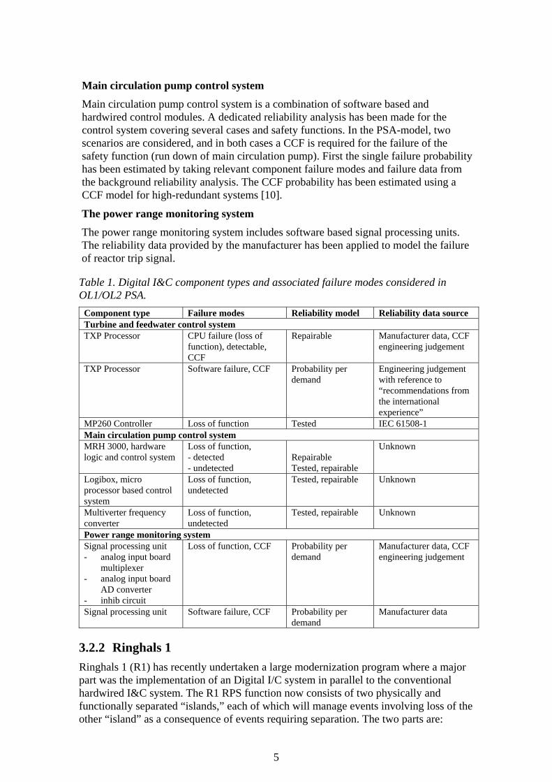
Main circulation pump control system
Main circulation pump control system is a combination of software based and hardwired control modules. A dedicated reliability analysis has been made for the control system covering several cases and safety functions. In the PSA-model, two scenarios are considered, and in both cases a CCF is required for the failure of the safety function (run down of main circulation pump). First the single failure probability has been estimated by taking relevant component failure modes and failure data from the background reliability analysis. The CCF probability has been estimated using a CCF model for high-redundant systems [10].
The power range monitoring system
The power range monitoring system includes software based signal processing units. The reliability data provided by the manufacturer has been applied to model the failure of reactor trip signal.
Table 1. Digital I&C component types and associated failure modes considered in OL1/OL2 PSA.
Component type Failure modes Reliability model Reliability data source Turbine and feedwater control system TXP Processor CPU failure (loss of
function), detectable, CCF
Repairable Manufacturer data, CCF engineering judgement
TXP Processor Software failure, CCF Probability per demand
Engineering judgement with reference to “recommendations from the international experience”
MP260 Controller Loss of function Tested IEC 61508-1 Main circulation pump control system MRH 3000, hardware logic and control system
Loss of function, - detected - undetected
Repairable Tested, repairable
Unknown
Logibox, micro processor based control system
Loss of function, undetected
Tested, repairable Unknown
Multiverter frequency converter
Loss of function, undetected
Tested, repairable Unknown
Power range monitoring system Signal processing unit - analog input board
multiplexer - analog input board
AD converter - inhib circuit
Loss of function, CCF Probability per demand
Manufacturer data, CCF engineering judgement
Signal processing unit Software failure, CCF Probability per demand
Manufacturer data
3.2.2 Ringhals 1 Ringhals 1 (R1) has recently undertaken a large modernization program where a major part was the implementation of an Digital I/C system in parallel to the conventional hardwired I&C system. The R1 RPS function now consists of two physically and functionally separated “islands,” each of which will manage events involving loss of the other “island” as a consequence of events requiring separation. The two parts are:
5

- OPS (Original Plant Section). The existing part of the plant including the reactor protection system, which will remain in principle unchanged. A number of process systems originally within the OPS are moved to the DPS, e.g. systems for pressure relief and core cooling. The OPS-Function will cope with loss of the DPS-Function.
- DPS (Diversified Plant Section). The DPS shall cope with events including loss of OPS (caused by events such as fire, earthquake, Lightning and CCF). The DPS-Function includes power supply, measurements, digital reactor protection system and process systems for execution of the safety functions, all independent of the OPS-Function.
The RPS within the DPS is realized with the programmable digital safety I&C system Teleperm XS (TXS).
The DPS is designed as a threefold redundant configuration with physical separation of the I&C. Each of the three divisions (S1, S2 and S3) comprises equipment for signal acquisition and conditioning, signal processing and component actuation. The division-related data can be exchanged among the computers so that each of them can monitor deviations among the redundant signals. Control of DPS safety functions for core cooling and residual heat removal are performed by dedicated control computers which acquire measurements and output signals from the three divisions to initiate and to stop the safety function.
A high level of detail has been chosen in the PSA modeling of the R1 Digital RPS, with the aim to screen components and failure modes in the up-coming As-Built stage based on calculated importance measures. The reason for this was the complex design of the Digital RPS. It was judged as very difficult to interpret functional dependencies at a pre-modeling stage, on a sufficiently detailed level in order to predict the importance of critical components and failure modes, and hence to develop acceptable and generic screening criterias.
The R1 PSA describes in detail the characteristics of the fail-safe design, e.g.:
- Failure modes and data distinguish between detected failures and undetected failures, i.e. latent failures.
- Fail-safe design only covers detected failures
- Undetected failures will challenge the RPS sequences
- Detected failures might cause “spurious” actuations
- The fault tree model considers the appliance of default values at detected failures of input signals
- The fault tree model consider different solutions for majority voting and different types of degraded voting logic in combination with if a failure is detected or latent:
- The fault tree model considers fail-safe actions applied to output channels controlling safety equipment at (detected) failures of controlling processor.
- The fault tree model considers that measurements or inputs can have different default values in different RPS sequences
- The fault tree model considers failures leading to spurious actuation or blocking of RPS sequences and safety components.
6

In Table 2 the considered components and failure modes in R1 PSA are given. The critical failures modes of these components differs for individual RPS Sequences and depends on 1) software designed default values and 2) type of design for degraded voting logic for each RPS Sequence.
Table 2. Digital I&C component types and associated failure modes considered i R1 PSA
Component type Failure modes1 Reliability model Reliability data source
Computer unit Software Failure, CCF Probability per demand Supplier database Processing Module Loss of function Periodically tested
(Undetected failure) Supplier database2
Loss of function Mission Time (Detected failure)
Supplier database2
Communication Module Loss of function Mission Time (Detected failure)
Supplier database2
Digital Input Module Loss of function Periodically tested (Undetected failure)
Supplier database2
Loss of function Mission Time (Detected failure)
Supplier database2
Digital Input Channel Loss of function Periodically tested (Undetected failure)
Supplier database2
Digital Output Module Loss of function Periodically tested (Undetected failure)
Supplier database2
Loss of function Mission Time (Detected failure)
Supplier database2
Digital Output Channel Loss of function Periodically tested (Undetected failure)
Supplier database2
Analog Input Module Loss of function Periodically tested (Undetected failure)
Supplier database2
Loss of function Mission Time (Detected failure)
Supplier database2
Analog Input Channel Loss of function Periodically tested (Undetected failure)
Supplier database2
Analog Output Module Loss of function Periodically tested (Undetected failure)
Supplier database2
Loss of function Mission Time (Detected failure)
Supplier database2
Analog Output Channel Loss of function Periodically tested (Undetected failure)
Supplier database2
Signal Conditioning Module
Loss of function Periodically tested (Undetected failure)
Supplier database2
Loss of function Mission Time (Detected failure)
Supplier database2
Programmable Analog Signal Conditioning Module
Loss of function Periodically tested (Undetected failure)
Supplier database2
Loss of function Mission Time (Detected failure)
Supplier database2
Subrack Loss of function Mission Time (Detected failure)
Supplier database2
1Both independent failure and CCF considered if nothing else stated. 2Additional calculations performed by RAB in order assign data to defined failure modes.
The input to the failure mode analysis is reliability data delivered by the supplier of the Teleperm XS units (Areva NP). This also sets the limit for the level of detail.
7

Software failures are not analyzed, or modeled, explicitly in the Ringhals 1 PSA since it at the time of the project were no methodology available to correctly describe and incorporate software failures into a fault tree model. Presently software failures are described only by CCF events considering failures within redundant TXS units.
3.2.3 Ringhals 2 Ringhals 2 (R2) has recently undertaken a large modernization program, TWICE, where a major part was the implementation of a new Westinghouse based RPS design. The reactor safety system of R2 now consists of a digital I&C design (RSS), and a diverse actuation system (DAS):
The RSS-system controls the reactor trip system and the main safety functions needed to minimize the consequences of the assumed accident, e.g. Safety Injection System, Auxiliary Feedwater System, Residual Heat Removal System, Containment Spray System, etc.
The DAS-system is a diverse actuation system that is able to control a safe shut down of the reactor if the ordinary RSS-system has failed, covering e.g. Overpower Reactor Trip, Secondary Heat Sink Reactor Trip, Auxiliary Feedwater System actuation, Turbine Trip and System and component-level manual control.
The RSS system concists of four redundant divisions that at the first level generates partial trip conditions and partial safety function actuations based on input parameters from the process monitoring, which are distributed to all four divisions in level two of the RSS where functional reactor trips and safety function actuations are performed. The Level 3 processing provides the interface to plant components, and also receives commands for manual control of all safety system components directly from the control room. The DAS consists of two divisions and provides a diversified function to the RSS, apart from the process measuring and component interfaces, by using a different I&C platform.
The R2 PSA models the RSS at a relatively high level of detail, while the DAS model is somewhat simplified. The general failure modes are “no activation signal” to components while spurious activation signals is not modelled. Detected failures are not modelled since their contribution is assumed to be neglible compared to undetected failures. The fraction of detected failures do however impact the effective test interval that is applied for the undetected failures. Due to this assumption the model does not has to take into account the major parts of the fail-safe features of the RPS. One exception has however been made where detected failures are modelled, see table 3 below. Failures of modelled logic modules include subcomponents such as processors, subrack, input and output modules.
Common Cause Failures are generally modeled between redundant, active and identical components in the RSS/DAS-functions, except for for component specific I&C which is assumed to be included in component CCF:s. The impact of software CCF:s is judged to be small and is only included for use in sensitivity analyses.
In Table 3 the considered components and failure modes in R2 PSA are given.
8

Table 3. Digital I&C component types and associated failure modes considered in R2 PSA
Component type Failure modes1 Reliability model Reliability data source
Bistable Processors2,3 Logic
Fails off Periodically tested (Undetected failure)
Supplier database
Integrated Logic Cabinet2,3
Fails off Periodically tested (Undetected failure)
Supplier database
Fails off Mission Time (Detected failure)
Supplier database
Local Coincidence Logic2,3
Fails off Periodically tested (Undetected failure)
Supplier database
Corrective maintenance Repairable Supplier database LCL Watch-dog Failure of detection Probability per demand Supplier database Communication Device4 Corrective maintenance Repairable Supplier database Component Interface Module
Fails off Periodically tested (Undetected failure)
Supplier database
Remote Node Controller Corrective maintenance Repairable Supplier database DAS module3 Fails off Periodically tested
(Undetected failure) Supplier database
DAS I/O module Fails off Periodically tested (Undetected failure)
Supplier database
1Both independent failure and CCF considered if nothing else stated. 2Includes failure of processor, subrack and I/O modules. 3 Software failures modelled for use in sensitivity analyses only. 4 Failure data only applied for Local Coincidence Logic communication links.
3.2.4 Loviisa 1/2 The original analogue automation of Loviisa NPP in Finland will be gradually replaced with digital automation with expected completion in year 2016. The automation renewal is implemented in overlapping stages for the two reactor units.
The automation renewal requires improvements on accident management principles and modifications on the plant defense-in-depth concept. Accident management principles are designed by using task categories which perform required safety functions and to meet the acceptance criteria given in regulatory guides. Automation systems include different levels, such as measurements, platforms and individual actuator controls. Short-term accident management, which is considered in the PSA, consists of five different task categories [11], also illustrated in Figure 1:
- Normal process control NPC (SPPA-T2000, OM690, FUM)
- Preventive protection PREV (TXS, QDS, AV42)
- Reactor protection RPS (TXS, QDS, AV42)
- Manual Backup of Reactor protection RPSMBU (non-programmable TXS, hard-wired)
- Automatic Backup of Reactor protection ABU (SPPA-T2000, OM690, AV42)
Equipment are safety classified based on the tasks they perform. The classification is carried out according to the Finnish regulatory guide [12]. There are four safety classes SC1 to SC4 and EYT (non-nuclear) class. Equipment performing the safety functions of a task category are of the same safety class. Normal operational and protection functions are performed in NPC and are classified as EYT (non-nuclear). Preventive
9

safety functions are performed in PREV and are classified as SC3. RPS performs the actual safety functions and is classified as SC2. The backup systems of RPS need to be diversified and are classified as SC3 in case of RPSMBU and as EYT in case of ABU. In the planned revision of Finnish nucelar regulatory guides, SC4 will disappear.
Figure 1. Loviisa 1/2 defence-in-depth principle in short-term accident management.
PSA has been and will be used along with the renewal project to support the design and to verify the fulfillment of the safety objectives. PSA has been used e.g. in assessment of changes into protection criteria, risk-informed safety classification and in the verification of adequacy of redundancy/diversity solutions.
The supplier has provided the utility with failure mode and effects analyses and fault tree analyses, which have been input to the actual PSA-model made by the utility. PSA is developed as the design goes on and new information is obtained.
Failure data based on histories exist for modules and hardware components which are similar or almost similar to components to be installed in Loviisa. Their single failure probabilities can be estimated reasonably well. There is no data for new software and CCF, except for some transmitters. Anyway, in the PSA-model dependencies are assumed between between different channels of RPS, between RPS and ABU, and between RPS and ABU and MBU. Present results indicate that the contribution of automation is small, about 1 % of CDF.
In Loviisa PSA the conditional core damage probabilities of spurious signals have been estimated and that information has been utilised in the design of the new automation.in order to eliminate or cancel their effects. Eventually they will be included in Loviisa PSA when the design has been completed.
The modelling of I&C components has been done in this stage in a high level focussing on verification of adequacy of redundancy/diversity solutions. Single failure events are excluded from the preliminary fault tree model because of their small risk importance. This means that all the numbers used in the model are engineering judgements of different CCF probabilities (probability of loss of function when demanded).
10

Similar Diverse p/T DCtransmitt. transmitt. transmitt. Software Hardware power AV42
A 5E-04 5E-04 1E-03 1E-03 1E-05 4,4E-04B 5E-05 1E-05 5E-05 5E-05C 1E-06 1E-06D 1E-07 1E-07E 0 5E-07F 1E-05 5E-06 0 1E-08 1E-05
A Single failureB CCF of single automation system (NPC, PREV, RPS, ABU or MBU)C CCF of programmed systems with same platforms or softwares (T2000 or TXS)D CCF of programmed systems with different platforms or softwares (T2000 and TXS)E CCF of programmed and non-programmed systems (MBUTXS - TXS/T2000)F Global CCF
Figure 2. Preliminary single and common cause failure probabilities for new automation components in Loviisa 1/2 automation renewal design phase PSA.
3.2.5 Comparison of approaches A comparision of the modelling approaches in the four different PSA:s has been performed and is presented in Table 4 to 7. The result can be seen as a first approach to define state-of-the-art and a rough draft of a taxonomy. The limitations of the performed study should however be taken into consideration before making any conclusions based on the result. Only four PSA:s are included, with different designs and to some extent also different I&C applications.
The comparison shows that among the four PSA:s there are four different approaches on how to describe the system reliability. In general the PSA:s are performed with different prerequisites. Also significant differences in assumptions and simplifications are found when compared, e.g. regarding coverage of I&C design features, level of detail and critical failure modes.
Concensus in all four PSA:s is hard to find, other than that all PSA:s analyses loss of RPS actuation and does not consider single software failures nor dynamic interactions between software and hardware. Only one PSA models spurious RPS actuations (though Loviisa PSA will include it at a later stage) and the same PSA is alone to consistently apply a high level of detail in the analysis.
However, most PSA:s models processor failure as a super component and also considers hardware and software CCF:s on a super component level. Also, three out of four PSA:s models undetected failures (tested) consistently.
Regarding references on failure data all PSA:s use supplier data for hardware failures, but when it comes to data for hardware and software CCF:s different solutions has been applied.
Parts of the differences in approach can be explained by different designs, status of the design and in some case by different I&C applications. Both the design and the application of the I&C of course sets some boundary conditions for the reliability analysis and in the choice of approch and modelling solutions. Chosen approach in the PSA is also dependent on the phase of the implementation process for the I&C system: design phase PSA, detailed design phase PSA or as-built PSA.
11

It should be noted that a detailed study is needed in order to penetrate these complex PSA models and to be able to fully understand and estimate the impact of assumptions and simplifications within the PSA:s. What appears to be similarly treated may not be and vice versa.
A state-of-the art may need to take into consideration differences in I&C design and reactor types (BWR/PWR), since this clearly have impact on parameters vital for the reliability model, e.g. level of detail, critical failure modes, consideration of fail-safe design, etc.
Table 4. Comparision of coverage of digital I&C design aspects in PSA. Modelling aspects OL1/2 R1 R2 LO1/2 Comments Loss of (RPS) Actuation ● ● ● ● Spurious (RPS) Actuation - ● - - Engineered Failure Detection
○ ● ● -
Failure of Eng. Failure Detection
○ - ○ -
Engineered Fail-Safe Actions
○ ● - -
Degraded Voting Logic s ● - - Intra Division Communication
○ ● ● -
Inter Division Communication
○ ● ● -
Dynamic Interactions - - - - ● Modelled as standard ○ Modelled as exception, special case or qualitatively s Screened out from the PSA model
Table 5. Comparision of coverage of failures and failure modes. Failures and modes OL1/2 R1 R2 LO1/2 Comments Hardware Failure Single Comp.
○ ● ○ -
Hardware Failure Super Comp.
● - ● s
Hardware CCF Single Comp.
○ ● ○ -
Hardware CCF Super Comp.
● - ● ●
Software Failure s - ○ - For sensitivity analysis Software CCF Single Comp.
s - - -
Software CCF Super Comp.
● ● - ● Application software
Undetected Failure ● ● ● - Detected Failure ● ● ○ - Spurious Failure - ○ ○ - Screened from analysis Corr. Maint. Single Comp. ○ ○ ○ - Corr. Maint. Super Comp. ○ ● ● - ● Modelled as standard ○ Modelled as exception, special case or qualitatively s Screened out from the PSA model
12

Table 6. Comparision of coverage of digital I&C hardware components. Hardware Components OL1/2 R1 R2 LO1/2 Comments Processor, Super Comp. ● - ● ● In OL1/OL2,
subcomponents’ failure modes analysed (FMEA & FT) in the background documents
Processor - ● - - Communication Module - ● ● - Digital Input/Output Module
- ● ○ -
Digital Input/Output Channel
- ● - -
Analog Input/Output Module
- ● - -
Analog Input/Output Channel
- ● - -
Signal Conditioning Module
- ● - -
Subrack - ● - ● Misc. Modules ● ● ● - Watchdog - - ○ - Controller Module for Continuous Closed-loop Control
- - - -
Priority unit - - - ● ● Modelled as standard ○ Modelled as exception, special case or qualitatively s Screened out from the PSA model
Table 7. Comparision of Failure Data References. Failure Data OL1/2 R1 R2 LO1/2 Hardware failure data Supplier data Supplier data Supplier data Supplier data
Hardware CCF Eng. Judge IEC 61508 / RAB
IEC 61508 / Supplier
Eng. Judge
Software CCF Supplier data / Eng. Judge
Supplier data N.A. Eng. Judge
3.3 Literature review The advent of digital I&C systems in nuclear power plants has created new challenges for safety analysis. Digital I&C systems include unique features, such as complex dynamic interactions and the usage of software, that can be difficult to take into account with traditional PSA methods such as with the event tree-fault tree approach. Generally, dynamic methodologies provide a more accurate representation of probabilistic system evolution in time than the fault tree/event tree approach. However, the dynamic models are on a trial stage and usually it is a difficult task to integrate dynamic models to existing PSAs. [9] summarized experiences of modelling digital systems in CSNI member countries and presents a set of recommendations for method development, data collection and analysis, and international cooperation.
13

3.3.1 Modelling digital I&C in PSA The applicability of traditional PSA methods (event tree-faul tree and markov modelling) for digital systems is survied in [2]. The report shows that the traditional methods are useful in the modelling but also indicates some limitations of the methods. However, the event tree- fault tree approach does not explicitly treat the timing of events in accident sequences and interactions with plant processes are implicitly and approximately considered. The construction of Markov models can be a laborious, time-consuming manual process, and the resulting transition matrix can be extremely large.
[2] identifies desirable characteristics for a probabilistic model of a digital system. Additionally, a preliminary list of areas where additional research could enhance the state-of-the-art of modelling digital system is identified. The utilization of traditional methods to model a digital feedwater control system is discussed in [13]. In the case study only the markov method was used as the order of component failures was considered important. The study demonstrated that the proposed approach is feasible for analyzing digital system. However, the intergration with a PSA based on the ET/FT method may not be a trivial task
[14] discusses the incorporation of a model of a digital RPS into a PSA. The work demonstrated that modelling the Digital RPS on an adequate level is challenging, and new approaches are required. An overview of the issues regarding the development of a static fault-tree-based risk model is presented in [15]. The complicated issues of digital system PSA are categorized into four groups based on their characteristics: hardware module, software, system, and safety function. [16] summarizes the key issues related to modeling the PSA of nuclear safety digital I&C systems and presents the probability risk quantification techniques corresponding to each of the issues.
[17] discusses risk insights associated with digital upgrade. In the development of the digital I&C PSA model a pragmatic approach was taken, as the quantification of software reliablity is a challenging problem. The research focused on important engineering insights that can be reach by understanding the role of the digital system with respect to the plant systems and the plant itself.
For representing the effect of I&C at a PSA level EDF has been developing since the 90’s the Compact Model. The Compact Model of digital I&C is a functional representation that comprises the main outcomes digital I&C experts’ safety and dependability assessments that can be shared with PSA experts and incorporated in a PSA model. [18] presents the Extended Compact Model. The purpose is to form a connection between the probabilistic assessment at plant level and the deterministic assessment at I&C level, by a step by step approach. The idea is to “descend” from PSA to critical parameters identification, and to “ascend” from deterministic assessment of factors contributing to I&C safety to its representation in a PSA.
FMEA is a well-known method for identifying failure modes of a system and their effects or consequences on the system. A few guidance documents for performing an FMEA are available, e.g. [19]. However, there are no specific guidance about how to perform FMEA for digital systems. FMEA by itself may not be a sufficient tool to determine how specific component-level failure modes affect digital systems [2]. Therefore, it could be usefull to utilize more sophisticated tools, such as simulation tools, to analyze the interactions between the components of a digital system and the effects of one or more failures.
14
A systematic failure modes and effects analysis (FMEA) approach is proposed in [20] for creating reliability models for digital instrumentation and control systems.
The absence of failure classification is a major issue in the representation of failure modes and mechnanism of digital I&C systems. A preliminary survey on failure modes and failure mechanisms in digital components and systems is presented in [21].
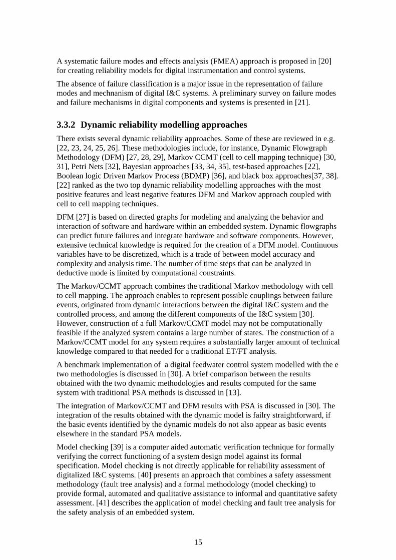
3.3.2 Dynamic reliability modelling approaches There exists several dynamic reliability approaches. Some of these are reviewed in e.g. [22, 23, 24, 25, 26]. These methodologies include, for instance, Dynamic Flowgraph Methodology (DFM) [27, 28, 29], Markov CCMT (cell to cell mapping technique) [30, 31], Petri Nets [32], Bayesian approaches [33, 34, 35], test-based approaches [22], Boolean logic Driven Markov Process (BDMP) [36], and black box approaches[37, 38]. [22] ranked as the two top dynamic reliability modelling approaches with the most positive features and least negative features DFM and Markov approach coupled with cell to cell mapping techniques.
DFM [27] is based on directed graphs for modeling and analyzing the behavior and interaction of software and hardware within an embedded system. Dynamic flowgraphs can predict future failures and integrate hardware and software components. However, extensive technical knowledge is required for the creation of a DFM model. Continuous variables have to be discretized, which is a trade of between model accuracy and complexity and analysis time. The number of time steps that can be analyzed in deductive mode is limited by computational constraints.
The Markov/CCMT approach combines the traditional Markov methodology with cell to cell mapping. The approach enables to represent possible couplings between failure events, originated from dynamic interactions between the digital I&C system and the controlled process, and among the different components of the I&C system [30]. However, construction of a full Markov/CCMT model may not be computationally feasible if the analyzed system contains a large number of states. The construction of a Markov/CCMT model for any system requires a substantially larger amount of technical knowledge compared to that needed for a traditional ET/FT analysis.
A benchmark implementation of a digital feedwater control system modelled with the e two methodologies is discussed in [30]. A brief comparison between the results obtained with the two dynamic methodologies and results computed for the same system with traditional PSA methods is discussed in [13].
The integration of Markov/CCMT and DFM results with PSA is discussed in [30]. The integration of the results obtained with the dynamic model is failry straightforward, if the basic events identified by the dynamic models do not also appear as basic events elsewhere in the standard PSA models.
Model checking [39] is a computer aided automatic verification technique for formally verifying the correct functioning of a system design model against its formal specification. Model checking is not directly applicable for reliability assessment of digitalized I&C systems. [40] presents an approach that combines a safety assessment methodology (fault tree analysis) and a formal methodology (model checking) to provide formal, automated and qualitative assistance to informal and quantitative safety assessment. [41] describes the application of model checking and fault tree analysis for the safety analysis of an embedded system.
15

The use of model checking for fault coverage analysis has been proposed in [42, 43]. Also efficient symbolic techniques for probabilistic model checking have been developed, e.g. [44].
3.3.3 Assessment of Software Reliability In spite of the unsolved issue of addressing software failures there seems be a consensus regarding some philosophical aspects of software failures and their use in developing a probabilistic model [45]. For the quantification of software failure rates and probabilities [45] identifies several general approaches. These approaches includes e.g. reliability growth methods, Bayesian belief network (BBN) methods, test based methods, rule based methods [46] and software metrics based methods [47, 48]. These methods are reviewed in [49].
Reliability growth models are based on the sequence of times between observed and repaired failures [50]. The models calculate the reliability and the current failure rate. Additionally, the reliability growth models can predict the time to next failure and required time to remove all faults.
The BBN methodology has been adapted to software safety assessment [3, 6] and the methodology can be considered as promising. One of the main drawbacks is that a different BBN has to be build for each software development environment. [51] suggests solving this problem by using generalized BBN templates which are not restricted to a specific development environment.
In test based methods a program is executed with selected data and the answer is checked against an ‘oracle’ [50]. A reliability measure can be generated, by running a number of tests and measuring the number of failures. Test-based reliability models assume that the input data profile used during the test corresponds to the input profile during real operation. However, often this correspondence cannot be guaranteed.
To assess software risk contribution [52, 53] presents an application of Context-based Software Risk Model (CSRM). CSRM allows to assess the contribution of software and software-intensive digital systems to overall system risk in a way that can be integrated with the PSA format used by NASA described in [54]. [55] describes PSA techniques for modelling digital I&C system software reliability focusing in the modelling of digital system software common-cause failures (CCF), and features of I&C systems that minimize potential CCF.
3.3.4 Summary of literature review Currently in PSA computer-based systems are mostly analyzed simply and conventionally. The conventional failure mode and effects analysis and failure tree modelling is utilized. As basic events CPU failures, application failures and CCFs between identical components are modelled.However it is not clear wich failure modes or system parts CCFs should be postulated. The primary goal is to model dependencies.
Dynamic methodologies can provide a more accurate representation of probabilistic system evolution in time than the FT approach. These methods included unique features that makes them suitable for specific applications, but they do not solve the problem of software reliability.
16

Software failures are in general mainly caused by systematic (i.e. design specification or modification) faults, and not on random errors. The software based systems cannot easily be decomposed into components, and the interdependence of the components cannot easily be identified and modelled. Applying software reliability models in the PSA context is not a trivial matter. Software reliability models usually rely on assumptions and statistical data collected from non-nuclear domain and therefore may not be directly applicable for software products implemented in nuclear power plants.
More important than the exact values of failure probabilities are the proper descriptions of the impact that software-based systems has on the dependence between the safety functions and the structure of accident sequences. It seems that the conventional FT-approach is sufficient for modelling RPS kind of functions.
4 User needs A questionnaire was issued to the utilities involved in the project (Ringhals, Fortum and TVO) in order to identify the need of methodology development from the utilities point of view.
Also a project workshop was held, open to all within the Nordic industry. The aim of the workshop was to present the interim results from the project, obtain opinions from the workshop participants and to plan the next phases of the project.
4.1 Questionnaire The questionnaire was based on four main areas of interest in the subject; Method Development, Data Collection and Analysis, Quality Assurance, and International Cooperation. Within each main area sub-areas neccessary to cover the needs of this project where given, i.e. only areas relevant for this project was included. The utilities (1-3) then ranked each sub-area with regard to relevancy for their needs. The ranking of each utility (low, medium, high) was given a score (1, 2, 3) and a total ranking was calculated.
The result of the questionnaire is presented in Table 8. The highest ranked areas are marked in red. The focus of the next project fase will in part be based on these results.
17

Table 8. Questionnaire on user needs. 1 2 3 Recommendation Sum of
ranking (High = 3, Medium = 2, Low = 1) Method Development Develop a taxonomy of hardware and software failure modes of digital components for common use
9 High High High
Develop guidelines regarding level of detail in system analysis and screening of components, failure modes and dependencies
9 High High High
Develop methods for analyzing software reliability 7 Low High High Develop approaches for assessing the impact of failure modes of digital components
8 High High Medium
Develop methods for estimating the effect of fault-tolerant features of a digital system on the reliability of the system’s components
7 High Medium Medium
Develop methods for incorporating fail-safe features of a DIC-system in a fault tree model
8 High High Medium
Develop methods for mapping and documentation of critical dependencies within a DIC-system
8 Middle High High
Develop methods for modelling of CCF between components (including software) in a DIC-system
9 High High High
Evaluate the need and approaches for addressing dynamic interactions
6 Low High Medium
Investigate alternative reliability analysis methods for digital systems
5,5 Low High Medium/Low
Develop approach for defining reliability requirements for DIC-systems
6 Low High Medium
Address human-system interfaces unique to digital systems and associated human reliability analysis
6 Middle Medium Medium
Data Collection and Analysis Collect hardware failure data, including common cause failures, that can be used for PSA purposes
8 High Medium High
Use operating experience for identifying software failure modes to be included in reliability models
7 Low High High
Quality Assurance Develop guidelines for quality assurance of a reliability analysis of a DIC-system
7 High Medium Medium
International Cooperation Sharing approaches, methods, probabilistic data, results, and insights gained from relevant projects among DIGREL financiers
9 High High High
Performing benchmark studies of existing reliability analyses of DIC-systems.
8 High Medium High
Publishing technical documents, such as “CSNI Technical Opinion Papers,” and papers in journals and conferences
5 Low Medium Medium
4.2 Conclusions from the workshop September 2010 A workshop was organize at VTT office in Espoo, Finland, on September the 14:th 2010. The objective of the workshop was to present interim results from the project, collect opinions from the participants and to plan upcoming phases of the project.
18

The workshops agenda contained presenting of the project aim, scope and basic concepts, summary of the international state-of-art, situation in Finland and Sweden, needs and problems and also information on the related WGRISK activity. The presentations were followed by discussions and in the end planning of the next steps.
The discussion items were What are the needs and key problems from the end user point of view? Where do we want to be after 1, 2, 5 years? What could be realistic goals? Which steps are needed to reach the goals?
The main discussion point was the software failures, how to model them, how to obtain failure data and the treatment of software CCF. The utilities are dependent on data provided by the vendors and there is no data available to make estimates on CCF, only single failure data. Software errors should be seen as CCFs per definition and they are often dependant on the environment and influence the whole system.
There is also a large uncertainty in how large part of the failure rate of hardware in a digital I&C system that is detectable and how large part that is undetected. The degree of detection are if not more important at least as important as the failure rate itself.
The justification of failure data used for software reliability is still an open issue. It is important that the utility, vendor and authority have a discussion in the early phase of the project and agree on the licensing process.
PSA has up to present been a fix state analysis, but not any more. One open question is if and how to address dynamic features in the PSA.
The summary of the discussion was that a generic guideline was requested were the right level of details is defined, use of failure data, modeling approach, common problems and a list of issues.
5 WGRISK activity proposal In 2007, the OECD/NEA CSNI directed the Working Group on Risk Assessment (WGRisk) to set up a task group (TG) to coordinate an activity on DIC system risk. The focus of this WGRisk activity was on current experiences with reliability modeling and quantification of these systems in the context of PSAs of NPPs. Two workshops were organised to share and discuss experiences with modeling and quantifying DIC systems. The participants recognized that several difficult technical challenges remain to be solved. One of the recommendations was to develop a taxonomy of hardware and software failure modes of digital components for the purposes of PSA. [9]
As a continuation, a new task proposal was made to WGRISK, which was accepted by WGRISK and CSNI in Spring 2010. The objectives with the new task is
- To develop technically sound and feasible failure modes taxonomy (or taxonomies if needed to address variations in modeling methods or data availability) for reliability assessment of digital I&C systems for PSA
- To provide best practice guidelines on the use of taxonomy in modelling, data collection and quantification of digital I&C reliability.
The activity focuses on failure modes taxonomy and its application to modelling, data collection and impacts on quantification. The following items will be considered (but not limited to):
- Protection systems and control systems,
19

- Hardware and software,
- Development, operation and maintenance,
- Failure detection and recovery means.
There are many different digital I&C failure mode taxonomies. An activity focused on development of a common taxonomy of failure modes can be seen as an important first step towards standardised digital I&C reliability assessment techniques for PSA. Needs from PSA will guide the work, meaning e.g. that the (digital) system and its failures are studied from their functional significance point of view. This is considered a meaningful way to approach the problem.
The taxonomy will be the basis of future modelling and quantification efforts. It will also help define a structure for data collection. The results of the activity can be directly used in the review of PSA studies.
The activity will take advantage from recent and ongoing R&D activities carried out in the member countries in this field. More PSA applications including digital I&C systems have been or are being prepared. Efforts to analyse operating experience from digital systems are in progress. This knowledge will be merged by inviting experts in the field to contribute to the activity.
A series of working meetings will organised in order to develop best practice guidelines on the topic, to share information and to plan future activities. The work plan includes the following steps
- Planning and nominations for task group (Spring-Summer 2010)
- First planning meeting of the task group, planning of the 1st Working meeting, design of the questionnaire/call for Working meeting (Fall 2010)
- 2 Working meetings during 2011: collection of taxonomies, identification of commonalities and differences between taxonomies, identification of needs for and uses of common taxonomy, planning of the preparation of the guidelines
- Development of the best practice guidelines by the task group:
o first draft of the taxonomy sent for commenting to the end users (Fall 2011)
o second draft Spring 2012
o final draft before the 2nd Working meeting (Fall 2012)
- 2 Working meetings during 2012: presentation of the best practice guidelines, endorsement, planning of future activities
- Report to the CSNI (2013).
The following organisations form the task group, being responsible for planning and organisation of work meetings and preparation of the best practice guidelines: VTT, Finland (leader); Risk Pilot, Sweden; IRSN, France; EDF, France; AREVA, France; GRS, Germany; KAERI, Korea; NRC, USA; Ohio State University, USA; NRI, Czech; JNES, Japan, VEIKI, Hungary, ENEL, Italy and NRG, the Netherlands.
Experts from countries with known experience in the topic will be invited to the work meetings (which are open to every organisation.) and to contribute to the project work. Representatives from all the WGRISK member countries are invited to take part in the
20

work. Participation of those countries with experience in modeling digital systems will be strongly encouraged.
The task has relation at least to the following projects:
- OECD/NEA Computer-based Systems Important to Safety (COMPSIS) Project
- OECD/NEA International Common-cause Failure Data Exchange (ICDE) Project
- IAEA NE-ICT activities (Network of Excellence for Supporting the Use of I&C Technologies for the Safe and Effective Operation of NPPs)
- Nordic NKS project on "Development of guidelines for reliability analysis of digital systems in PSA context".
6 Plan for next phases 6.1 Objectives The objective with the project is to provide guidelines to analyse and model digital systems in PSA context, using traditional reliability analysis methods (FMEA, Fault tree analysis). Based on the pre-study questionnaire and discussions with the end users in Finland, Sweden and within the WGRISK community, the following focus areas have been identified for the activities:
1. Develop a taxonomy of hardware and software failure modes of digital components for common use
2. Develop guidelines regarding level of detail in system analysis and screening of components, failure modes and dependencies
3. Develop approach for modelling of CCF between components (including software).
6.2 Content, methods and phases The project will consist of two closely interrelated activities:
1. WGRISK activity focusing on the development of best practice guidelines on failure modes taxonomy for reliability assessment of digital I&C systems for PSA.
2. The complementary Finnish-Swedish activity covering also objectives 2 and 3.
In order to work with the two other focus areas, the existing Nordic PSA models will be reviewed in a comparative manner. It is expected that the NPSAG members provides sufficient access to models and documentation to be used as the background material in the project.
Based on results from the WGRISK activity and the Nordic comparison study, guidelines will be developed.
Table 9 presents the milestones as planned in December 2010.
21

Table 9. Milestones of the NKS/DIGREL project.
Start T = 1.1.2011 T + 3M WGRISK annual meeting and task group meeting T + 5M WGRISK public working meeting in Washington D.C: T + ~9M
WGRISK/NKS public seminar in Finland/Sweden
T + 12M Interim report for NKS T + 15M WGRISK annual meeting and task group meeting T + 18M Draft guidelines on failure modes taxonomy (WGRISK) T + xM 1–2 WGRISK/NKS working meetings during 2012 T + 24M Interim report for NKS T + 36M WGRISK final report, NKS final report
6.3 Results and deliverables The result of the WGRISK activity will be a document “Best practice guidelines on failure modes taxonomy for reliability assessment of digital I&C systems for PSA”.
The result of the parallel NKS activity will a document which has a broader scope: “Guidelines for reliability analysis of digital systems in PSA context.”
In addition, interim work reports will be prepared annually and workshops will be arranged to the end users to disseminate the results.
7 Conclusions Currently there is no consensus on reliability analysis approaches. Traditional methods have limitations and more dynamic approaches are still in trial stage and can be difficult to apply in full scale PSA-models. Also the number of PSA:s worldwide including reliability models of digital I&C systems are very few.
The study of existing Nordic PSA:s including digital I&C that has been performed in this project shows a wide range of approaches and solutions to the challenges given by digital I&C, and also indicates that no state-of-the-art currently exists.
However, the study shows some areas where the different PSA:s agree and also gives the basis for development of a common taxonomy for reliability analysis of digital I&C.
The use of alternative reliability methods, such as dynamic methodologies, can provide a more accurate representation of probabilistic system evolution in time than the FT approach, but they do not solve the problem of software reliability.
It is still an open matter whether software reliability needs to be explicitly modelled in the PSA. However, the most important concerning software realiability is proper descriptions of the impact that software-based systems has on the dependence between the safety functions and the structure of accident sequences. In general it seems that the conventional FT-approach is sufficient for modelling RPS kind of functions.
The work started here will continue by means of the ongoing WGRISK activity and a continuation project has also been proposed to Nordic financiers. The following focus areas have been identified for the activities:
1. Develop a taxonomy of hardware and software failure modes of digital components for common use
22

2. Develop guidelines regarding level of detail in system analysis and screening of components, failure modes and dependencies
3. Develop approach for modelling of CCF between components (including software).
8 References 1. Recommendations on assessing digital system reliability in probabilistic risk
assessments of nuclear power plants, NEA/CSNI/R(2009)18, OECD/NEA/CSNI, Paris, 2009. (http://www.nea.fr/nsd/docs/2009/csni-r2009-18.pdf)
2. Chu, T.L., Martinez-Guridi, G., Yue, M., Lehner, J., Samanta, P. Traditional Probabilistic Risk Assessment Methods for Digital Systems, NUREG/CR-6962, U.S.NRC, Washington D.C., 2008, http://www.nrc.gov/reading-rm/doc-collections/nuregs/contract/cr6962/
3. Haapanen P, Helminen A. Failure mode and effects analysis of software-based automation systems. STUK-YTO-TR 190. STUK, Helsinki 2002. http://www.stuk.fi/julkaisut/tr/stuk-yto-tr190.pdf
4. Haapanen P, Helminen A, Pulkkinen U. Quantitative reliability assessment in the safety case of computer-based automation systems. STUK-YTO-TR 202. STUK, Helsinki 2004. http://www.stuk.fi/julkaisut/tr/stuk-yto-tr202.pdf
5. Helminen A. Reliability estimation of safety-critical software-based systems using Bayesian networks. STUK-YTO-TR 178. STUK, Helsinki 2001. http://www.stuk.fi/julkaisut/tr/stuk-yto-tr178.pdf
6. Helminen A, Pulkkinen U. Reliability assessment using Bayesian network. Case study on quantative estimation of a software-based motor protection relay. STUK-YTO-TR 198. STUK, Helsinki 2003. http://www.stuk.fi/julkaisut/tr/stuk-yto-tr198.pdf
7. Karanta, I., Holmberg, J.-E., Maskuniiitty, M. Reliability analysis of digital I&C systems in nuclear power plants, In Puska, E-K. (ed.) SAFIR2010, The Finnish Research Programme on Nuclear Power Plant Safety 2007–2010, Interim Report, VTT Research Notes 2466, VTT, Espoo, 2009, p. 485–494. http://www.vtt.fi/inf/pdf/tiedotteet/2009/T2466.pdf
8. Karanta, I., Maskuniitty, M., Reliability of digital control systems in nuclear power plants — Modelling the feedwater system, VTT-R-01749-08, VTT, Espoo, January 2009.
9. Organization for Economic Co-operation and Development, Recommendations on Assessing Digital System Reliability in Probabilistic Risk Assessments of Nuclear Power Plants, NEA/CSNI/R(2009)18, December 17, 2009.
10. Mankamo, T., Kosonen, M., Dependent failure modeling in highly redundant structures—Application to BWR safety valves, Reliability Engineering & System Safety, Volume 35, Issue 3, 1992, Pages 235-244.
11. Jänkälä, K. Risk-Informed Safety Classification in Plant Automation Modifications of Loviisa NPP. PSAM 10, Seattlw, Washington, June 7-11, 2010, paper 209.
12. Nuclear power plant systems, structures and components and their safety classification, Guide YVL 2.1, Radiation and Nuclear Safety Authority, Helsinki, 2000.
23

13. Chu, T.L., Yue, M., Martinez-Guridi, G., Mernick, K., Lehner, J., Kuritzky, A., Modeling a Digital Feedwater Control System Using Traditional Probabilistic Risk Assessment Methods, NUREG/CR-6997 BNL-NUREG-90315-2009, U.S. NRC, 2009.
14. Authén, S., Wallgren, E., Eriksson, S., Development of the Ringhals 1 PSA with Regard to the Implementation of a Digital Reactor Protection System, 10th International Probabilitstic Safety Assessment & Management Conference, PSAM 10, Seattlw, Washington, June 7-11, 2010, paper 213.
15. Kang H. G., Jang S.-C., Issues And Research Status For Static Risk Modeling Of Digitalized Nuclear Power Plants, Sixth American Nuclear Society International Topical Meeting on Nuclear Plant Instrumentation, Control, and Human-Machine Interface Technologies, NPIC&HMIT 2009, Knoxville, Tennessee, April 5-9, 2009
16. Shi, L., Enzinna, R., Yang, S., Blodgett. S., Probabilistic Risk Assessments of Digital I&C in Nuclear Power Plant, 10th International Probabilitstic Safety Assessment & Management Conference, PSAM 10, Seattlw, Washington, June 7-11, 2010, paper 173.
17. Blanchard, D., Torok, R., Risk Insights Associated with Digital Upgrades, 10th International Probabilitstic Safety Assessment & Management Conference, PSAM 10, Seattlw, Washington, June 7-11, 2010, paper 453
18. Thuy, N., Deleuze, G., A Mixed Approach to Assess the Impact of I&C in PSA, Sixth American Nuclear Society International Topical Meeting on Nuclear Plant Instrumentation, Control, and Human-Machine Interface Technologies, NPIC&HMIT 2009, Knoxville, Tennessee, April 5-9, 2009.
19. IEEE Guide for General Principles of Reliability Analysis of Nuclear Power Generating Station Safety Systems, IEEE Std. 352, Institute of Electrical and Electronics Engineers, Inc., 1987.
20. Chu, T.-L., Yue, M., Martinez-Guridi, G., Lehner, J., A Generic Failure Modes and Effects Analysis (FMEA) Approach for Reliability Modeling of Digital Instrumentation and Control (I&C) Systems, 10th International Probabilitstic Safety Assessment & Management Conference, PSAM 10, Seattlw, Washington, June 7-11, 2010, paper 82.
21. Cetiner, S. M., Korsah, K., Muhlheim, M. D., Survey On Failure Modes And Failure Mechanisms In Digital Components And Systems, Sixth American Nuclear Society International Topical Meeting on Nuclear Plant Instrumentation, Control, and Human-Machine Interface Technologies, NPIC&HMIT 2009, Knoxville, Tennessee, April 5-9, 2009
22. Aldemir, T., Miller, D.W., Stovsky, M.P., Kirschenbaum, J., Bucci, P. A.W. Fentiman1 , L.T. Mangan1: Current State of Reliability Modeling Methodologies for Digital Systems and Their Acceptance Criteria for Nuclear Power Plant Assessments, NUREG/CR-6901"
23. Björkman, K., Digital automation system reliability analysis – Literature survey, VTT-R-08153-09, Espoo, March 2010
24. Karanta, I., Björkman, K., Holmberg, J-E., Maskuniitty, M., Reliability assessment of computer controlled systems, SIAS 2010 - The 6th International Conference on Safety of Industrial Automated Systems. Tampere, 14.-15.6.2010 SIAS 2010 Proceedings. Suomen Automaatioseura (2010), 6 p.
25. Borysiewicz, M.J., Borysiewicz, M.A., Garanty, I., Kozubal, A.: Part 5 – Assessment and Management of Risk, Quantitative Risk Assessment (QRA), Monography Models and techniques for health and environmental hazard assessment and management”, Warsaw 2006.
24

26. Kaufman, L. M., Johnson, B. W., Embedded Digital System Reliability and Safety Analyses, NUREG/GR-0020, U.S. NRC, Washington, D.C. (2001).
27. Garrett, C.J, Guarro, S.B., Apostolakis, G.E.: The Dynamic Flowgraph Methodology for Assessing the Dependability of Embedded Software Systems, IEEE Trans. on Systems, Man and Cybernetics Vol. 25. No. 5, 824-840
28. Garrett, C. J., Apostolakis, G.E. Automated hazard analysis of digital control systems, Reliab. Engng & System Safety, 77, 1-17 (2002)
29. Yau, M., Guarro, S., Apostolakis, G.: Demonstration of the Dynamic Flowgraph Methodology using the Titan II Space Launch Vehicle Digital Flight Control System, Reliability Engineering and System Safety 49 (1995) 335-353
30. Aldemir, T., Guarro, S., Kirschenbaum, J., Mandelli, D., Mangan, L.A., Bucci, P., Yau, M., Johnson, B., Elks, C., Ekici5, E., Stovsky, M.P. Miller, D.W., Sun, X., Arndt, S.A., Nguyen, Q. Dion, J.,: A Benchmark Implementation of Two Dynamic Methodologies for the Reliability Modeling of Digital Instrumentation and Control Systems, NUREG/CR-6985
31. Bucci, P., Kirschenbaum, J., Mangan, L. A., Aldemir, T., Smith, C., Wood, T.: Construction of event-tree/fault-tree models from a Markov approach to dynamic system reliability, Reliability Engineering and System Safety 93 (2008) 1616–1627"
32. Labeau, P.E., Smidts, C., Swaminathan, S: Dynamic reliability: towards an integrated platform for probabilistic risk assessment, Reliability Engineering and System Safety 68 (219254), Elsevier Science Limited 2000, 36p
33. Pearl, J. Probabilistic reasoning in intelligent systems: Networks of plausible inference. Morgan Kaufmann Publishers, San Mateo, CA, 1988.
34. Doguc, O., Ramirez-Marquez, J. E., A generic method for estimating system reliability using Bayesian networks, Reliability Engineering & System Safety, Volume 94, Issue 2, February 2009
35. Kelly, D. L., Smith, C. L.: Bayesian inference in probabilistic risk assessment—The current state of the art, Reliability Engineering & System Safety, Volume 94, Issue 2, February 2009, Pages 628-643
36. Bouissou, M.,: Boolean logic driven markov processes: A powerful new formalism for specifying and solving very large markov models, In Proceedings of the 6th International Conference on Probabilistic Safety Assessment and Management 2002
37. Musa, J.D., Okumoto, K: A Logarithmic Poisson Execution Time Model for Software Reliability Measurement, Proceedings of Seventh International Conference on Software Engineering, 230-238, Orlando, FL, 1984.
38. Schneidewind, N.F., Keller, T.W: Applying Reliability Models to the Space Shuttle, IEEE Software, 28-33, July 1992
39. Clarke, Jr. E. M., Grumberg, O., Peled, D. A., Model Checking, The MIT Press, (1999)
40. Koh, K. Y., Seong, P. H.: SACS2: A Dynamic and Formal Approach to Safety Analysis for Complex Safety Critical Systems, Sixth American Nuclear Society International Topical Meeting on Nuclear Plant Instrumentation, Control, and Human-Machine Interface Technologies, NPIC&HMIT 2009, Knoxville, Tennessee, April 5–9, 2009
41. Ortmeier, F., Schellhorn, G., Thums, A., Reif, W., Hering, B., Trappschuh, H., Safety analysis of the height control system for the Elbtunnel, Reliability Engineering & System Safety, Volume 81, Issue 3, Safety, Reliability and Security of Industrial Computer Systems, September 2003, Pages 259-268
25

42. Bozzano, M., Villafiorita, A;, The FSAP/NuSMV-SA Safety Analysis Platform;,International Journal on Software Tools for Technology Transfer, Volume 9, Number 1, February 2007 , pp. 5-24(20)
43. Bingham, S., Lach, J., Exhaustive Integrated Circuit Fault Coverage Analysis Using Formal Methods, Sixth American Nuclear Society International Topical Meeting on Nuclear Plant Instrumentation, Control, and Human-Machine Interface Technologies, NPIC&HMIT 2009, Knoxville, Tennessee, April 5-9, 2009
44. Kwiatkowska, M., Norman, G., Parker, D., PRISM: Probabilistic Model Checking for Performance and Reliability Analysis. ACM SIGMETRICS Performance Evaluation Review, 36(4), pages 40-45. March 2009.
45. Chu, T.-L,, Martinez-Guridi, G., Yue, M., Samanta, P., Vinod, G., Lehner, J., Establishing a Philosophical Basis for Probabilistic Modeling of Software Failures, 10th International Probabilitstic Safety Assessment & Management Conference, PSAM 10, Seattlw, Washington, June 7-11, 2010, paper 84
46. International Electrotechnical Commission, “Function Safety of Electrical/Electronic/Programmable Safety-Related Systems,” Parts 1-7, IEC 61508, various dates.
47. Smidts, C., Li, M., Software Engineering Measures for Predicting Software Reliability in Safety Critical Digital Systems, NUREG/GR-0019, November 2000.
48. Smidts, C., Li, M., Preliminary Validation of a Methodology for Assessing Software Quality, NUREG/CR-6848, July 2004.
49. Chu, T.-L., Yue, M., Martinez-Guridi, G., Lehner, J., Review of Quantitative Software Reliability Methods, Brookhaven National Laboratory Letter Report, Digital System Software PRA JCN N-6725 September 2010.
50. Dahll, G., Liwang, B., and Pulkkinen, U., “Software-Based System Reliability,” Technical Note, NEA/SEN/SIN/WGRISK(2007)1, Working Group on Risk Assessment (WGRISK) of the Nuclear Energy Agency, January 26, 2007.
51. Eom, H.-S., Park, G.-Y., Kang, H.-G., Jang, S.-C.,: Reliability Assessment Of A Safety-Critical Software By Using Generalized Bayesian Nets, Sixth American Nuclear Society International Topical Meeting on Nuclear Plant Instrumentation, Control, and Human-Machine Interface Technologies, NPIC&HMIT 2009, Knoxville, Tennessee, April 5-9, 2009
52. Yau, M., Guarro, S.,Application of Context-based Software Risk Model (CSRM) to Assess Software Risk Contribution in Constellation Project PRAs, 10th International Probabilitstic Safety Assessment & Management Conference, PSAM 10, Seattlw, Washington, June 7-11, 2010, paper 186
53. Guarro, S. Risk-Informed Safety Assurance and Probabilistic Assessment of Mission-Critical Software-Intensive Systems, NASA Technical Paper AR 07-01; JSC-CN-19704. 2007
54. Vesely, W., Stamatelatos, M., Dugan, J., Fragola, J., Minarick III, J., Railsback, J., Fault Tree Handbook with Aerospace Applications; NASA; 2002.
55. Enzinna, B., Shi, L., Yang, S., Software Common-Cause Failure Probability Assessment, Sixth American Nuclear Society International Topical Meeting on Nuclear Plant Instrumentation, Control, and Human-Machine Interface Technologies, NPIC&HMIT 2009, Knoxville, Tennessee, April 5-9, 2009
26

Bibliographic Data Sheet NKS-230 Title Guidelines for reliability analysis of digital systems in PSA context —
Phase 1 Status Report
Author(s) Stefan Authen 1, Kim Björkman 2, Jan-Erik Holmberg 2, Josefin Larsson 1
Affiliation(s) 1 Risk Pilot, Sweden and 2 VTT, Finland
ISBN 978-87-7893-301-0
Date December 2010
Project NKS-R / DIGREL
No. of pages 29 No. of tables 9 No. of illustrations 2 No. of references 55
Abstract
Digital protection and control systems are appearing as upgrades in older nuclear power plants (NPPs) and are commonplace in new NPPs. To assess the risk of NPP operation and to determine the risk impact of digital system upgrades on NPPs, quantitative reliability models are needed for digital systems. Due to the many unique attributes of these systems, challenges exist in systems analysis, modeling and in data collection. Currently there is no consensus on reliability analysis approaches. Traditional methods have clearly limitations, but more dynamic approaches are still in trial stage and can be difficult to apply in full scale probabilistic safety assessments (PSA). The number of PSA:s worldwide including reliability models of digital I&C systems are few. A comparison of Nordic experiences and a literature review on main international references have been performed in this pre-study project. The study shows a wide range of approaches, and also indicates that no state-of-the-art currently exists. The study shows areas where the different PSA:s agree and gives the basis for development of a common taxonomy for reliability analysis of digital systems. It is still an open matter whether software reliability needs to be explicitly modelled in the PSA. The most important issue concerning software reliability is proper descriptions of the impact that software-based systems has on the dependence between the safety functions and the structure of accident sequences. In general the conventional fault tree approach seems to be sufficient for modelling reactor protection system kind of functions. The following focus areas have been identified for further activities: 1. Common taxonomy of hardware and software failure modes of digital components for common use 2. Guidelines regarding level of detail in system analysis and screening of components, failure modes and dependencies 3. Approach for modelling of CCF between components (including software).
Key words Digital I&C system, probabilistic safety assessment, reliability, nuclear power plant safety
Available on request from the NKS Secretariat, P.O.Box 49, DK-4000 Roskilde, Denmark. Phone (+45) 4677 4045, fax (+45) 4677 4046, e-mail [email protected], www.nks.org