Embed Size (px)
Citation preview
PG L. The ValueProvider for
Power GenerationManagement
Power Generation l Instrumentation & Controls
ES 680 the TELEPERM XP Engineering SystemHans-Martin Wismath

TELEPERM XP Power Generation l Instrumentation & Controls 2/23CE_R7_e, Hans-Martin Wismath, 05/2003
PG L. The ValueProvider for
Power GenerationManagement
The Structure of TELEPERM XP

TELEPERM XP Power Generation l Instrumentation & Controls 3/23CE_R7_e, Hans-Martin Wismath, 05/2003
PG L. The ValueProvider for
Power GenerationManagement
ES 680 the TELEPERM XP world of engineering
Plant bus
Logic diagrams
&>1
Cabinet allocations Process operationProcess informationProcess management
MT T
TTP
CP
OT OT
CP
CP CP
CP CP
SU
PU
CP CP
ES
CP
CP CP CP
OM 650 DS 670 ES 680
AP; APFFUM; FUM-F; SIM
Topology diagram

TELEPERM XP Power Generation l Instrumentation & Controls 4/23CE_R7_e, Hans-Martin Wismath, 05/2003
PG L. The ValueProvider for
Power GenerationManagement
The step by step engineering concept
Compact solutionPowerful network solution to be used for the engineering of large plants
OTOT
PU SU ES
AP
ET DT
DS
Plant bus
Terminal bus
CU-OM/ES
AP; APFFUM; FUM-F; SIM
TELEPERM XP Power Generation l Instrumentation & Controls 5/23CE_R7_e, Hans-Martin Wismath, 05/2003
PG L. The ValueProvider for
Power GenerationManagement
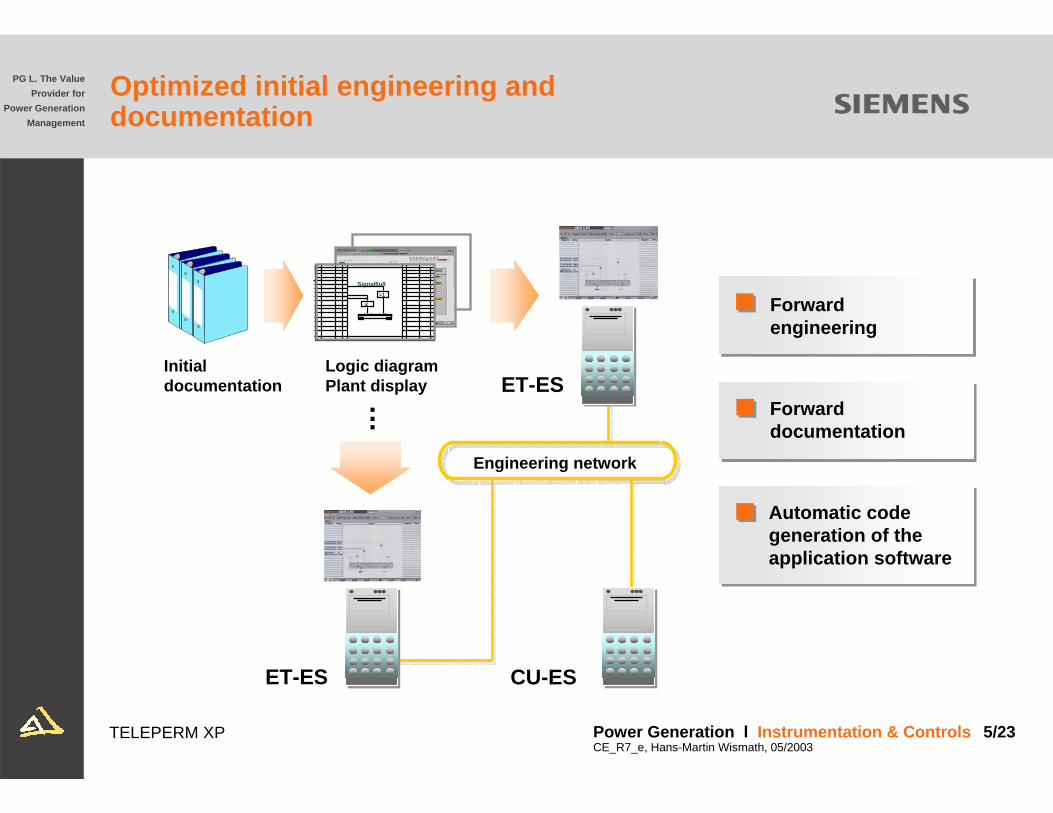
Initial documentation
Logic diagramPlant display
Signalfluß
&
>1
Engineering network
...
CU-ES
ET-ES
Automatic code generation of theapplication software
Forward documentation
Forwardengineering
ET-ES
Optimized initial engineering anddocumentation

TELEPERM XP Power Generation l Instrumentation & Controls 6/23CE_R7_e, Hans-Martin Wismath, 05/2003
PG L. The ValueProvider for
Power GenerationManagement
Optimized commissioning and documentation on site
On site workstation
Modifications and supplements are made via the screen
Application software isdownloaded via theplant bus and theterminal bus
Automatic generationof the applicationsoftware structure
Automatic generationof the documentation
OTOT
OM
AP
ES
Plant bus
Terminal bus
final documentation
AP; APF; FUM; FUM-F; SIM
TELEPERM XP Power Generation l Instrumentation & Controls 7/23CE_R7_e, Hans-Martin Wismath, 05/2003
PG L. The ValueProvider for
Power GenerationManagement
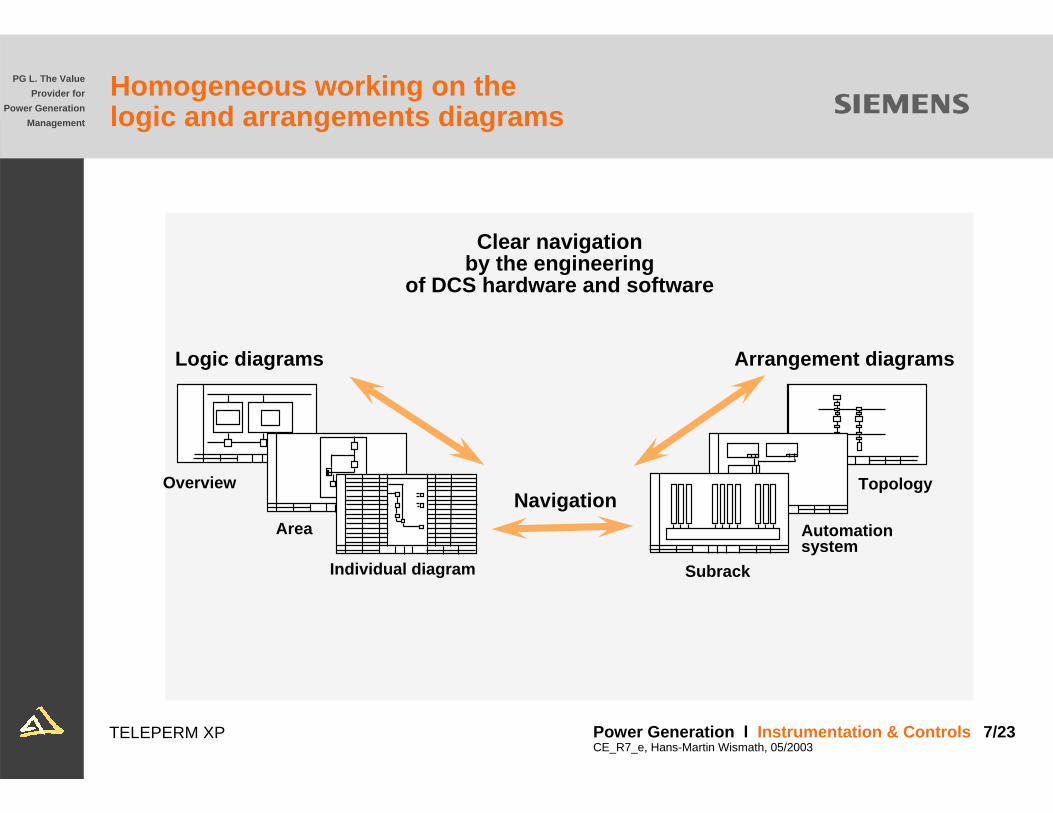
Arrangement diagrams
Topology
Automationsystem
Subrack
Logic diagrams
Overview
Area
Individual diagram
Navigation
Clear navigation by the engineering
of DCS hardware and software
Homogeneous working on the logic and arrangements diagrams

TELEPERM XP Power Generation l Instrumentation & Controls 8/23CE_R7_e, Hans-Martin Wismath, 05/2003
PG L. The ValueProvider for
Power GenerationManagement
Resolution
Density
Overview level
Area level
Individual level
Top down structure of the logic diagrams
TELEPERM XP Power Generation l Instrumentation & Controls 9/23CE_R7_e, Hans-Martin Wismath, 05/2003
PG L. The ValueProvider for
Power GenerationManagement
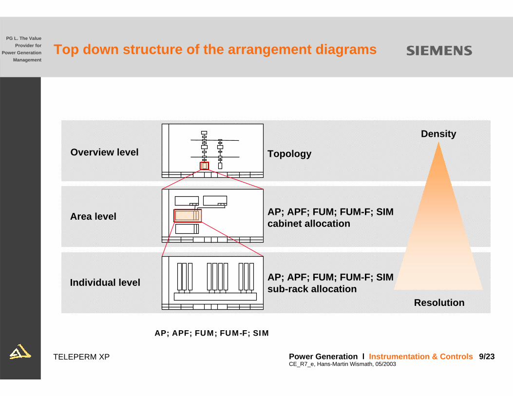
Resolution
Density
Overview level
Area level
Individual level
Topology
AP; APF; FUM; FUM-F; SIMcabinet allocation
AP; APF; FUM; FUM-F; SIMsub-rack allocation
AP; APF; FUM; FUM-F; SIM
Top down structure of the arrangement diagrams

TELEPERM XP Power Generation l Instrumentation & Controls 10/23CE_R7_e, Hans-Martin Wismath, 05/2003
PG L. The ValueProvider for
Power GenerationManagement
Design of the arrangement diagrams with ES680- topology
Topology of the TELEPERM XP DCS
CP
OT
CP
SUPU
CP
CP
CP CP
ES
CP
CP
OT
CP
OSM/ESMOSM/ESM
OSM/ESM OSM/ESM

TELEPERM XP Power Generation l Instrumentation & Controls 11/23CE_R7_e, Hans-Martin Wismath, 05/2003
PG L. The ValueProvider for
Power GenerationManagement
Design of the arrangement diagrams AS 620 cabinet allocation diagram
IM
IMFUM
IM
IMFUM
AP-A AP-B
Graphical design of the cabinet allocation with sub-racks

TELEPERM XP Power Generation l Instrumentation & Controls 12/23CE_R7_e, Hans-Martin Wismath, 05/2003
PG L. The ValueProvider for
Power GenerationManagement
IM
IM
SIM
SIPOS 5
AP-A AP-B
(ET200 M)
Design of the arrangement diagrams AS 620 field device alignment
Graphical design of the field device alignment

TELEPERM XP Power Generation l Instrumentation & Controls 13/23CE_R7_e, Hans-Martin Wismath, 05/2003
PG L. The ValueProvider for
Power GenerationManagement
Design of the arrangement diagrams AS 620 sub-rack allocation diagram
Kanal Anlagenkennzeichen Sig.2 MAJ15 CP0122 MAJ15 CP012
2 MAJ15 CL007
XQ01XQ02
XQ01
12
43
56
87
910
1211
13
1514
16
Einbauplatz GerätebeschreibungBlock/SchrankEtage/Steckplatz
SchlüsselErzeugnisnummerGerät
oK. zurück schließen
2 CRF01
Info
.AG019
FUM531
FUM310
FUM230
FUM511
FUM511
FUM280
FUM280
FUM531
FUM310
FUM230
FUM280
FUM511
KA GB GA TT KB AS AS AS AS BAZ RA XB
003 011 018 027 035 043 051 054 067 075 083 091 099 107 115 123 131 139 147 155 163
EU902
Baugruppen ParameterFUM230GA
Graphical design of the sub-rack allocation with modules

TELEPERM XP Power Generation l Instrumentation & Controls 14/23CE_R7_e, Hans-Martin Wismath, 05/2003
PG L. The ValueProvider for
Power GenerationManagement
I&C solutions are designed withthe logic diagram
ESGOutputs
Inputs Signal flow

TELEPERM XP Power Generation l Instrumentation & Controls 15/23CE_R7_e, Hans-Martin Wismath, 05/2003
PG L. The ValueProvider for
Power GenerationManagement
Standard symbols to design logic diagrams
Standard symbols
for the functions
- measurement- open loop control- closed loop control

TELEPERM XP Power Generation l Instrumentation & Controls 16/23CE_R7_e, Hans-Martin Wismath, 05/2003
PG L. The ValueProvider for
Power GenerationManagement
The AP; APF; FUM; FUM-F; & SIM logic diagrams
Graphical design of the signal flow
Modifications ofparameters viawindow technique
Automatedcode generation

TELEPERM XP Power Generation l Instrumentation & Controls 17/23CE_R7_e, Hans-Martin Wismath, 05/2003
PG L. The ValueProvider for
Power GenerationManagement
The dynamic logic diagram
Navigation betweenthe logic diagrams ofAS620 B & APFautomation systems
Actual processingstatus of all inputs, outputs and calculated results
Selection of the logic diagram viaplant identificationcode (KKS)
TELEPERM XP Power Generation l Instrumentation & Controls 18/23CE_R7_e, Hans-Martin Wismath, 05/2003
PG L. The ValueProvider for
Power GenerationManagement
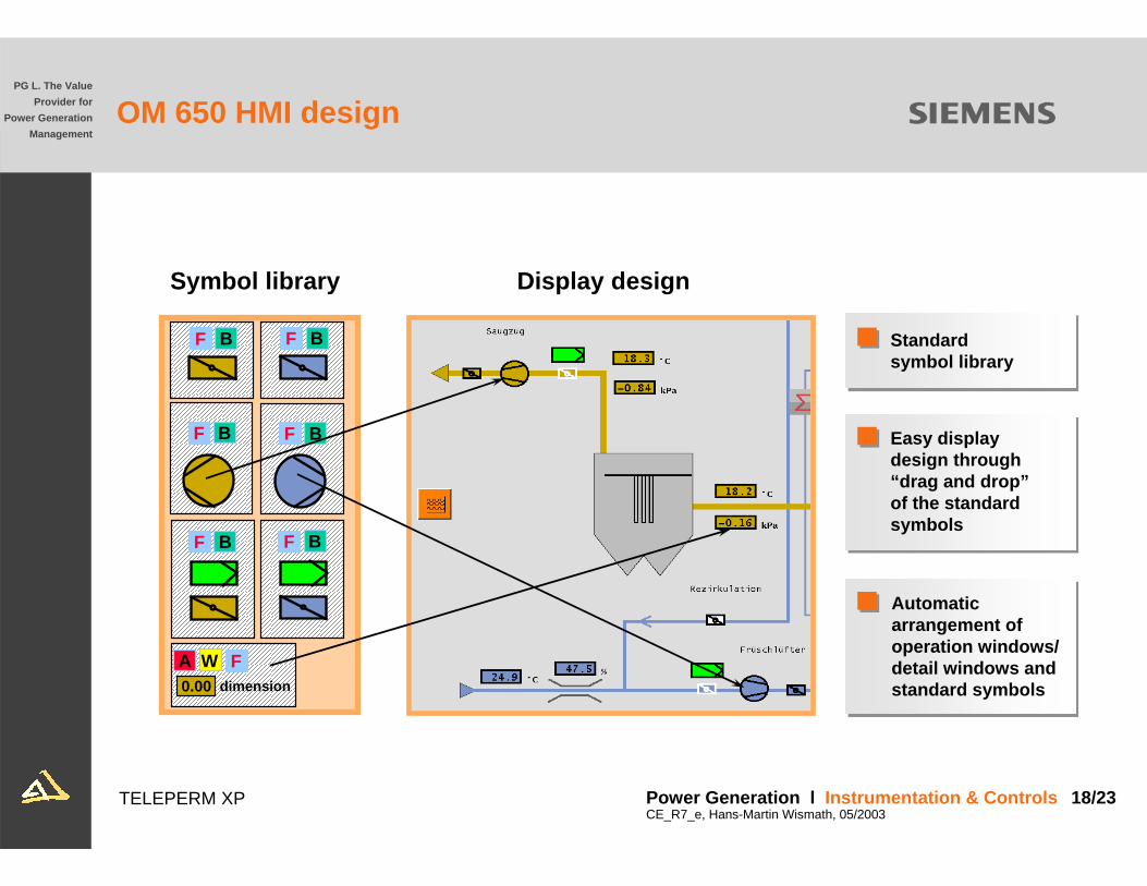
OM 650 HMI design
Symbol library
0.00 dimensionA W F
BF
BF BF
BF
BF BF
Display design
Standardsymbol library
Easy display design through “drag and drop”of the standardsymbols
Automaticarrangement ofoperation windows/ detail windows andstandard symbols

TELEPERM XP Power Generation l Instrumentation & Controls 19/23CE_R7_e, Hans-Martin Wismath, 05/2003
PG L. The ValueProvider for
Power GenerationManagement
The process interface of OM 650
Parameters includingplant identification code
ID Fan
FD Fan
KKSPlant identification code signal
7 HNC10 DL0017 HNC10 AA001
XQ01XQ01
PIC PAR
YareaYP01YP01
CLC flue/gas damperFlue/gas damper
Recirculation

TELEPERM XP Power Generation l Instrumentation & Controls 20/23CE_R7_e, Hans-Martin Wismath, 05/2003
PG L. The ValueProvider for
Power GenerationManagement
AP
Centralized engineering and diagnostic functions of field devices
* Process Device Manager
PROFIBUS-PA
ES 680SIMATIC PDM *Improved commissioning
remote changing of parameterssimple and fast changing of parameters
Simple maintenanceremote diagnosticsextended and detailed diagnosison demand maintenance by
maintenance alarmsmaintenance diagnostic functions

TELEPERM XP Power Generation l Instrumentation & Controls 21/23CE_R7_e, Hans-Martin Wismath, 05/2003
PG L. The ValueProvider for
Power GenerationManagement
Authorization level
ETOT/DT
DS ES OM
AP
OT
ET:Definition of user classes and privileges
ET:Definition of users and their assignment to a user class and to a process area via graphic user interface
OT:The operation functions that can be selected depend on the user login
Multi-stage ”skeleton key” function
Plant bus
Terminal bus
TELEPERM XP Power Generation l Instrumentation & Controls 22/23CE_R7_e, Hans-Martin Wismath, 05/2003
PG L. The ValueProvider for
Power GenerationManagement
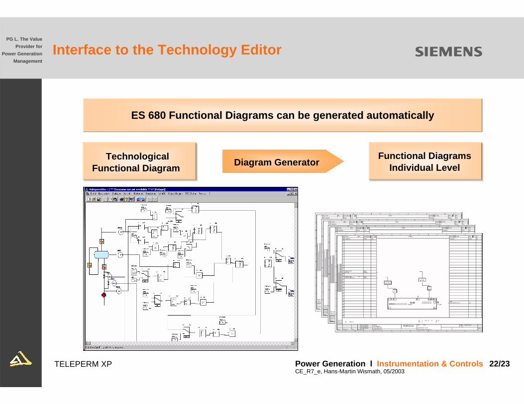
Interface to the Technology Editor
ES 680 Functional Diagrams can be generated automatically
TechnologicalFunctional Diagram
Functional Diagrams Individual LevelDiagram Generator
TELEPERM XP Power Generation l Instrumentation & Controls 23/23CE_R7_e, Hans-Martin Wismath, 05/2003
PG L. The ValueProvider for
Power GenerationManagement
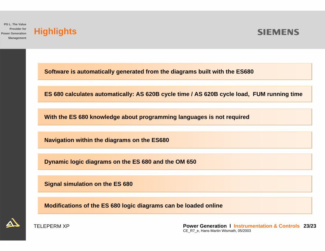
Navigation within the diagrams on the ES680
Modifications of the ES 680 logic diagrams can be loaded online
Signal simulation on the ES 680
Dynamic logic diagrams on the ES 680 and the OM 650
With the ES 680 knowledge about programming languages is not required
ES 680 calculates automatically: AS 620B cycle time / AS 620B cycle load, FUM running time
Software is automatically generated from the diagrams built with the ES680
Highlights