Embed Size (px)
Citation preview

Nicolas TjioeCSE 520
Wednesday 11/12/2008
Hyper-Threading in NetBurst Microarchitecture
David KoufatyDeborah T. Marr
Intel
Published by the IEEE Computer SocietyVolume 23, Issue 2,
March-April 2003 Page(s):56 - 65

Traditional Processor Design
• Higher Clock SpeedPipeline the microarchitecture to finer granularities called super pipelining
• Instruction Level Parallelism (ILP)In-Order vs Out-of-Order
• Cache HierarchyData on the cache reduces the frequency of access to the slower main memory
Design Cont.
• Existing techniques add die-size and power costs. • CMP: Full set of execution and architectural resources.• Time-slice multithreading.• Simultaneous multithreading (SMT).

Hyper-Threading (HT)
• HT introduces the SMT approach to the Intel architecture.• A single physical processor appears as multi-core
processors. One copy of the architecture state for each logical processor sharing a single set of physical execution resource.
• HW: more instructions, SW: schedule more threads• HT added less than 5% to the relative chip size and
maximum power requirements.

Microarchitecture choice & tradeoffsPartition:
• Dedicating equal resources to each logical processor.
• Simplicity and low complexity.
• Good for high structure’s utilization and unpredictable.
• Eg: Pipeline Queue
Threshold:
• Flexible resource sharing with a limit on the maximum resource usage.
• Ideal for small structures where the resource utilization is bursty and predictible.
• Eg: Processor Scheduler
Full Sharing:
• Flexible resource sharing with no limit on the maximum resource usage.
• Good for large structures in which the working set-size are variable.
• Eg: Processor caches.

Shared vs Partitioned Queue
Dark color: Slower Thread, Light color: Faster Thread

HT Resources
Duplicated:• Register Renaming Logic• Instruction Pointer• ITLB• Return Stack Predictor
Partitioned:• Reorder Buffer (ROB)• Load/Store Buffer• Scheduling queues, uop queues.
Shared:• Caches: Trace cache, L2.• Execution unit.• Microarchitectural Registers.

Front-End PipelineExecution Trace Cache:Trace Cache (TC) stores the decoded instructions called Microoperations (uops).
Microcode ROM:For complex instruction where TC sends microcode instruction pointer to the Microcode ROM.
Instruction Translation Lookup Buffer (ITLB):In case of Trace Cache Miss, ITLB receives the request from TC to deliver new instructions and it translates the next instruction pointer address toa physical address. Streaming buffers is 64 bytes.
IA32 Instruction Decode:Decoding is only needed for instructions that miss the TC. Alternate between threads, in this way we need two copies of decoder logic.
Uop Queue:Each logical processor has half the entries only (Partitioned). Sends uops from Front-end pipeline to the Out-of-Order Execution Engine.

Out-of-Order Execution Engine
Allocator:It will alternate select uops from the logical processor at every clock cycle. Signal stall if limit is reached.
Register Rename:Rename the IA32 registers (8) into the machine physical registers (128). Allow the instruction to run at the same time with another instruction that use the same IA32 registers. Uses RAT to keep track of the registers.
Instruction Scheduling:Four uops schedulers are used to schedule different type of uops for different execution units. Each scheduler has its own queue of 8-12 entries
Retirement:Retirement logic alternate between two logical processors to track which uops are ready to be retired. Data is written to the L1 Data cache.
Each logical processor can use up to a maximum of 63 ROB, 24 load buffers and 12 store buffers.

Dispatch & Execution Units
Maximum # of instructions that can be dispatched is 6:- Two microinstructions on Port 0.- Two microinstructions on Port 1.- One microinstruction on Port 2.- One microinstruction on Port 3.
Same port has fast unit combine with the slow unit.
Port 2, 3 is used for memory operations (load and store).
After execution, uops are placed in the ROB.
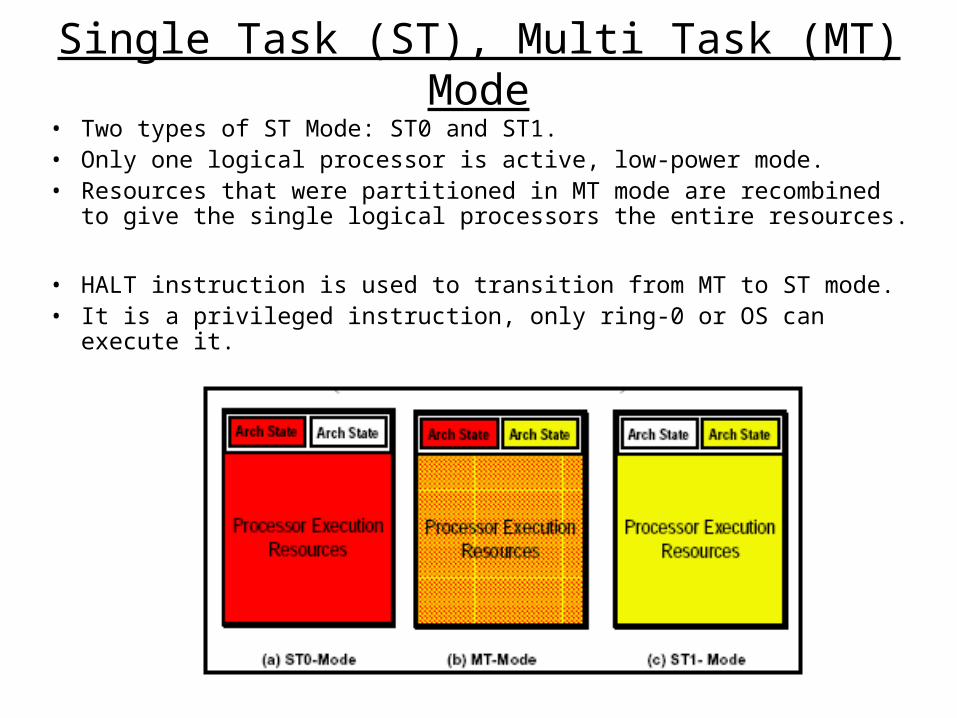
Single Task (ST), Multi Task (MT) Mode• Two types of ST Mode: ST0 and ST1.• Only one logical processor is active, low-power mode.• Resources that were partitioned in MT mode are recombined to give
the single logical processors the entire resources.
• HALT instruction is used to transition from MT to ST mode. • It is a privileged instruction, only ring-0 or OS can execute it.

Experiment Setup
Processor Intel Pentium 4 with HT
enabled/disabled
Motherboard Intel Desktop Board D850EMV2
RAM 256-Mbyte PC1066 RDRAM
GPU Leadtek WinFast A250 Ultra TD GeForce 4/ nVidia GeForce 4 4x AGP graphics
Software - Intel Application Accelerator v2.2.2128.
- Intel C and Fortran compilers 5.01 for
SPEC
- DirectX 8.1
- Intel Chipset Software Installation
Utility v4.00.1009
OS Windows XP(build 2600)

Result
Cache hit rate and overall performance impact for a fully shared cache normalized against values for a partitioned cache

Multithreading & Multitasking Performance
HT Performance on Multithreaded Software Package
HT Performance on Multitasking workloads

Conclusions
• HT improves multithreaded applications by having each logical processor run software threads from the same application.
• HT speeds up workload consisting of multitasking applications by multitasking. Each logical processor run threads from different applications.
• Nehalem (Intel i7) plan to be released in Q4 2008. It scales up to 8 physical cores (16 logical processors).

Additional References:
• Hyper-Threading Technology Architecture and Microarchitecture
ftp://download.intel.com/technology/itj/2002/volume06issue01/art01_hyper/vol6iss1_art01.pdf
• http://www.hardwaresecrets.com/article/235/6