Embed Size (px)
Citation preview

WELDING RESEARCH
NOVEMBER 2007, VOL. 86-s360
ABSTRACT. A common weld bead defectthat occurs at high fusion welding speedsis the periodic undulation of the weld beadprofile, also known as humping. In thepresent study, when using argon shieldinggas, 0.9-mm-diameter ER70S-6 andER70S-3 electrode wires, and weldingpowers between 9 and 12 kW during high-speed gas metal arc welding of SAE-AISI1018 cold rolled steel plate, swinging spraymetal transfer was observed and the weld-ing speed was found to be limited to 15mm/s by the onset of the periodic hump-ing phenomenon. However, rotationalmetal transfer was observed when usingreactive shielding gases at these powersand the welding speed was limited to 22 mm/s by the onset of a new, as yet un-reported, weld defect that was distinctlydifferent from humping. This new high-speed defect is referred to as the discon-tinuous weld bead defect, since the defec-tive weld bead is broken up into severalgood bead segments by aperiodic or irreg-ularly spaced valleys or depressions wheremelting of the base metal occurred but nofiller metal was deposited. The results alsoindicated that nominal electrode wirecomposition did not appear to play a sig-nificant role in the formation of the hump-ing or the discontinuous weld bead defects.
A LaserStrobe™ video imaging systemwas used to obtain video images of typicalsequences of events during the formationof the humping and discontinuous weldbead defects. From these images, the dis-continuous weld bead defect was found tobe caused by the inconsistent, aperiodicdeposition of molten filler metal duringrotational filler metal transfer mode whenusing reactive shielding gases. The longmolten filler metal string on the end of theelectrode wire was erratically fragmented
and required time to re-form prior to theresumption of the transfer of filler metal.The temporary disruption of filler metaldeposition created a filler-metal-free de-pression that broke up the otherwise goodweld bead, thereby forming the discontin-uous weld bead defect. The irregular frag-mentation of the molten filler metal stringduring rotational transfer and subsequentformation of the aperiodic discontinuousweld bead defect are phenomena thathave not previously been observed or re-ported in the open literature.
Introduction
Welding is a ubiquitous process and anintegral part of most manufacturing in-dustries such as the construction, ship-building, aerospace, automotive, petro-chemical, and electronics industries. Toremain competitive in today’s manufac-turing environment, companies must con-tinuously improve their productivity with-out sacrificing the quality of theirproducts. Increases in productivity will re-duce overall production costs, therebymaintaining and strengthening the com-pany’s competitiveness. Overall produc-tion costs can usually be reduced by eval-uating the productivity of the weldingprocesses used. For many welded prod-ucts, an increase in productivity often re-quires use of higher welding speeds. Fre-quently, this can be achieved throughoptimizing or automating existing weldingprocesses. In certain cases, switching tonewer high-energy-density weldingprocesses will also result in higher welding
speeds and increases in productivity.In order to weld at higher welding
speeds, the heat input of all fusion weldingprocesses must be increased to maintainthe same amount of energy input per unitlength of weld required for melting offiller and base metals (Refs. 1–3), other-wise, the weld cross section will decreaseand eventually no melting of the basemetal will occur. While increasing weldingspeed and heat input will provide the de-sired productivity increase, continued in-creases of the welding speed is in practicelimited by the deterioration of the qualityof weld bead profile. One of the most com-monly occurring geometric defects thathas been observed at high welding speedsis the humping phenomenon (Refs. 4–6).An example of a humped gas metal arc(GMA) weld bead is shown in Fig. 1.Humping can be described as a periodicundulation of the weld bead with regularlyspaced humps and valleys. Figure 2 showstransverse sections at a valley and a hump,respectively, of the humped GMA weldbead in Fig. 1. Although the depth of pen-etration is the same for both transversesections, there is more weld metal accu-mulation at the hump. The humping de-fect compromises the mechanical integrityof the weld joint, thereby limiting thewelding speed and thus overall productionrates.
Nguyen et al. (Ref. 5) and Soderstromand Mendez (Ref. 6) have recently re-viewed the literature related to high-speedfusion weld bead defects, their causes, andtechniques that have been used to increasewelding speed. Humping of the weld beadhas been the most commonly observedhigh-speed weld defect. It has been re-ported to occur in both nonautogenouswelding processes, such as GMA welding(Refs. 7–9) and autogenous processessuch as gas tungsten arc (GTA) welding(Refs. 10, 11), laser beam welding (LBW)(Refs. 12, 13), and electron beam welding(EBW) (Refs. 14–16).
Bradstreet (Ref. 7) was the first to re-port the formation of humped welds dur-ing GMA welding of plain carbon steelusing spray transfer mode. He found that
The Discontinuous Weld Bead Defect inHigh-Speed Gas Metal Arc Welds
A new type of high-speed gas metal arc weld bead defect was observed and characterized
BY T. C. NGUYEN, D. C. WECKMAN, AND D. A. JOHNSON
KEYWORDS
Gas Metal Arc WeldingHumpingWeld DefectsArgon Shielding GasReactive Shielding GasesDiscontinuous Weld BeadsCarbon Steel
T. C. NGUYEN was with the University of Water-loo. He is now at the School of Engineering andInformation Technology, Conestoga College,Kitchener, Ont., Canada. D. C. WECKMAN andD. A. JOHNSON are with the Department of Me-chanical Engineering, University of Waterloo, Wa-terloo, Ont., Canada.
Nguyen Nov 2007corr layout:Layout 1 10/9/07 2:28 PM Page 360

WELDING RESEARCH
-s361WELDING JOURNAL
the humping phenomenon is periodic andinfluenced by the welding speed, the weld-ing voltage, the angle of the electrode withrespect to the workpiece, and other para-meters. He also observed that reactiveshielding gases such as Ar-CO2 and Ar-O2mixes significantly increased the limitingwelding speed before humping occurredand argued that this was a result of thelower surface tension and improved wet-ting that occurred when the reactive gaseswere used. In later studies, Nishiguchi etal. (Refs. 8, 9) developed a parametricmap of arc voltage vs. welding speed forGMA welding of mild steel using short cir-cuit metal transfer mode while Nguyen etal. (Ref. 17) used Ar and two reactiveshielding gases and spray transfer mode tocreate a map of GMA welding power ver-sus welding speed. These parametric mapsshowed regions of process parametersthat produced good weld beads and re-gions that resulted in humping and otherweld bead defects. In both cases, theyfound that humping occurred as the weld-ing speed was increased above a certaincritical welding speed and that there wasan inverse relationship between this criti-cal welding speed and the welding voltageor power used, i.e., as the welding voltageor power was increased, humping oc-curred at lower welding speeds.
In autogenous welding processes,humping has been found to be periodicand influenced by welding process para-meters such as welding speed, weldingpower, type of shielding gas, ambient pres-sure, electrode geometry, travel angle,and energy density at the workpiece, etc.(Refs. 10–16). Several attempts have beenmade to express the relationship betweenthese process variables and the onset ofhumping (Refs. 7–21). Typically, these in-cluded process maps that show the onsetof humping with respect to welding speedand welding current or welding power. Oneach of these process maps, weldingprocess parameters such as the shieldinggas composition, the torch angle, or theGTA electrode geometry are normallykept constant.
Several models of the periodic hump-ing phenomenon have been proposed.These include the Rayleigh Jet Instabilitymodel first proposed by Bradstreet (Ref.7) and its modifications by Gratzke et al.(Ref. 22), the Arc Pressure model byPaton et al. (Ref. 23), and the Supercriti-cal Flow model by Yamamoto and Shi-mada (Ref. 10). In a subsequent study ofhumping during GTA welding of stainlesssteel, Mendez and Eagar (Refs. 19–21) ar-gued that humping was caused by periodicpremature solidification of the thin liquidfilm at the bottom of the arc gouged re-gion of the weld pool. This choked off flowof molten metal to the back of the weld
pool and resulted in the initiation of a newhump further along the weld bead. Thesemodels suggest that fluid flow, arc pres-sure, metallostatic pressure, capillaryforce, and lateral instability of a cylindri-cal jet of molten weld metal and prema-ture solidification of the thin film ofmolten metal in the arc gouged region ofthe weld pool are all possible factors re-sponsible for the periodic humping phenomenon.
Based on video imaging of GMA weldsmade on mild steel plates and corroborat-ing experiments, Nguyen et al. (Refs. 5,17) have recently proposed a curved walljet model of humping in nonautogenouswelding processes such as GMA welding.Figure 3 shows a schematic diagram of thismodel of humping in high-speed GMAwelding. As the welding speed increases,the weld pool becomes elongated, shal-low, and narrow. Also, the electrode, thewelding arc, and the metal droplet streammove forward and closer to the leadingedge of the weld pool, i.e., the longitudi-nal distance from the leading edge of theweld pool to the location where the fillermetal droplet impinges the top surface ofthe weld pool, d, decreases. The combinedactions of the arc force and the dropletmomentum create a depression or gougedregion at the front of the weld pool thatcontains a thin layer of liquid metal un-derneath the welding arc. In addition, thefiller metal droplets hit the sloping leadingedge of the weld pool and this molten fillermetal is then redirected toward the tail ofthe weld pool at high velocity through asemicircular curved wall jet similar inshape to the valley portion of the humpedweld bead shown in Figs. 1 and 2A, drag-ging with it any liquid metal in the front ofthe weld pool from the melting base metal.At the tail of the weld pool in Fig. 3, themolten weld metal accumulates to form aswelling that is drawn into a spherical beadshape by surface tension (see humps inFigs. 1 and 2B) as molten metal is fed intothe swelling from the front of the weldpool through the wall jet. As the weldingarc continues to move to the left along theweld joint, the wall jet shown in Fig. 3 be-comes increasingly elongated and thethermal mass of molten metal inside thewall jet becomes distributed over a longerdistance until continued solidification of
the weld and the molten metal in the elon-gated wall jet chokes off the flow of moltenmetal to the swelling. Solidification of thewall jet illustrated in Fig. 3 forms the val-ley typically observed between swellings ina humped GMA weld bead such as thoseshown in Figs. 1 and 2A. Initiation andgrowth of a new swelling closer to the arcand further along the weld bead occursvery soon after fluid flow in the wall jet ischoked off. This sequential formation of aswelling or hump at the tail of the weldpool and solidification of the wall jet is aperiodic phenomenon where the humping
Fig. 1 — A bead-on-plate GMA weld in plain car-bon steel exhibiting the humping weld bead defect.
Fig. 2 — Transverse sections of the GMA weldshown in Fig. 1 at the following: A — A valley, andB — a hump.
A
B
Fig. 3 — The curved wall jet model for the periodichumping phenomenon during high-speed GMAW(after Nguyen et al. (Refs. 5, 17)).
Nguyen Nov 2007corr layout:Layout 1 10/9/07 2:32 PM Page 361

WELDING RESEARCH
NOVEMBER 2007, VOL. 86-s362
frequency has been shown to increase withincreasing welding speed or decreasingwelding power (Ref. 24).
During their study of the humping phe-nomena in high-speed GMA welding ofplain carbon steel, Nguyen et al. (Refs. 5,17, 24) observed a change in the humpedweld bead morphology when welds wereperformed using reactive shielding gasesand welding powers greater than 9 kW.Figure 4 shows three GMA welds thatwere produced at 40 mm/s welding speedusing a reactive shielding gas and increas-ing welding powers of 6, 8, and 11 kW.
These welds have beencleaned by sandblast-ing to clearly revealthe different geomet-ric features of thebead. As shown in Fig.4A, a good GMA weldwas produced whenusing 6 kW weldingpower and humping
was observed when the welding power wasincreased to 8 kW — Fig. 4B. However, asshown in Fig. 4C, when the welding powerwas further increased to 11 kW, the GMAweld produced showed a distinctly differ-ent type of geometric weld defect that isclearly not humping. The regular, periodicbehavior of humping was no longer evi-dent and the curved wall jet in the valleysof the high-speed weld bead defect was nolonger present. This new high-speed de-fect is referred to here as the discontinu-ous weld bead defect, because the defec-
tive weld bead as shown in Fig. 4C is bro-ken up into several good bead segments byaperiodic or irregularly spaced valleys ordepressions where melting of the basemetal occurred but no filler metal was de-posited. In addition, while the normallyobserved decrease in critical weldingspeed with increasing welding power wasevident at the lower powers when hump-ing occurred, the critical welding speedwas not affected by the welding powerwhen this new weld bead defect was ob-served. This particular aperiodic high-speed GMA weld bead defect has notbeen previously identified or reported inthe literature (Refs. 1–5, 17, 24). The ob-jectives of the present study (Ref. 24),therefore, were to observe, identify, ex-perimentally validate, and understand thephysical mechanisms responsible for thisnew discontinuous weld bead defect thatoccurred during high-speed GMA weld-ing of plain carbon steel.
Fig. 4 — Top view of GMA welds produced using a reactive shielding gas, 40 mm/s welding speed. A— 6 kW; B — 8 kW; and C — 11 kW welding power.
Fig. 5 — A schematic diagram showing various compo-nents of the LaserStrobe™ video imaging system.
Fig. 6 — Top view of GMA welds produced using 6.3 kW welding power,argon shielding gas, and at various welding speeds.
Fig. 7 — A close-up top view of a bead-on-plate GMA weld showing theaperiodic discontinuous weld bead defect.
A
B
C
Nguyen Nov 2007corr layout:Layout 1 10/9/07 2:38 PM Page 362

WELDING RESEARCH
-s363WELDING JOURNAL
Experimental Apparatusand Procedures
In the present study, bead-on-plateGMA welds were made using a FanucARC Mate 120i 6-axis welding robot anda Lincoln PowerWave™ 455 power supplyoperating in constant voltage mode withan integrated Power Feed 10 wire feederover a wide range of preset welding speedsand welding powers. A PC-microcom-puter was used with Labview™ softwareand National Instruments™-based data-acquisition system to record the weldingvoltage and current. Voltage between thecontact tip and the workpiece was mea-sured at the rate of 1000 samples/s using aLEM™ LV100 voltage transducer and thewelding current was measured using aLEM™ LT505-S current transducer. Themeasured voltages, V (V), and currents, I (A), were then postprocessed to calcu-late the time averaged welding power, P(W), using P = V × I.
A LaserStrobe™ video system (Ref.25) was used to observe and to record im-ages of the humping phenomenon duringbead-on-plate GMA welding of plain car-bon steel plate. As shown schematically inFig. 5, the LaserStrobe™ video imagingsystem consisted of a video camera, avideo recorder (VCR), a pulsed nitrogen(N2) laser strobe with fiber-optic beam de-livery, a data-acquisition system, and apersonal computer that acted as a systemcontroller. The pulsed N2 laser strobe wasused to overwhelm the intense radiationof the GMA welding arc since the laserlight was much brighter than the lightcoming from the welding arc at the N2laser wavelength (Ref. 25). The laser-illuminated scene was viewed by a videocamera equipped with a CCD video sen-sor, a narrow band-pass filter centered onthe 337.1-nm wavelength of the N2 laser,and an image intensifier that was also usedas a high-speed electronic shutter. Theimage intensifier limits the resolution ofthe LaserStrobe™ image to about 420 linepairs in the horizontal direction (Ref. 25).The computer synchronized the camera’selectronic shutter with the laser pulses.The combination of temporal filteringprovided by the electronic shutter, N2laser pulse synchronization, and spectralfiltering from the narrow band-pass filterallowed unobstructed viewing of theevents taking place during the formationof humped GMA welds without the in-tense light from the welding arc. Duringfilming, the video camera was mounted ona fixture that moved along with the GMAwelding torch.
All bead-on-plate GMA welds weremade in the flat position on degreased 6.5-mm- (¼-in.-) thick cold-rolled SAE-AISI 1018 plain carbon steel plates using
0.9-mm- (0.035-in.-) diameter ER70S-3and ER70S-6 electrode wires and a 22-mmcontact tip-to-workpiece distance. The ma-jority of GMA welding experiments wereperformed using ER70S-6 electrode wire.However, ER70S-3 electrode was also em-ployed to determine the effects of the dif-ferences in chemical composition of thefiller metal on the formation of high-speedweld defects. The nominal chemical com-positions of these GMAW electrode wiresare as listed in Table 1 (Ref. 3). Both ofthese electrodes have relatively high levelsof the deoxidizing elements, Mg and Si.The ER70S-6 electrode wire has the high-est concentrations of Mg and Si and is oftenrecommended for applications that usehigh welding current or GMAW over steelplates that are covered with light rust,whereas the ER70S-3 electrode is recom-mended when welding clean steel withargon-based shielding gases (Ref. 3). In allcases, the working angle of the GMAW gunwas 90 deg and the travel angle was 0 deg.
Three different welding-grade shield-ing gases were used: argon, Mig MixGold™ (MMG™1) and TIME™2. Thecomposition of each shielding gas is listedin Table 2. In this study, argon was an inertshielding gas while MMG™ and TIME™
were reactive shielding gases due to theiroxygen (O2) and carbon dioxide (CO2)contents.
To determine the usable weldingspeeds at each power level, the weld beadprofiles were examined and the maximumwelding speed that produced a non-humped or acceptable weld bead wasrecorded. For example, Fig. 6 containsphotographs showing the top view ofGMA welds produced using 6.3 kW weld-ing power, argon shielding gas, and 10, 11,and 12 mm/s welding speeds, respectively.In Fig. 6, the welds produced at 10 mm/swelding speeds or slower were classified asgood welds, since the weld beads show nosignificant variation in weld dimensions orshape along the length of the weld. How-ever, at 11 mm/s welding speed, the weld
bead begins to exhibit intermittentswellings that are separated by valleys.The occurrence of the humps and valleysbecomes consistently periodic at 12 mm/swelding speed. Thus, the difference be-tween good weld beads and a humpedweld can be clearly identified by the sig-nificant variations in weld bead dimen-sions and shape that occur along thelength of the humped weld bead and theoccurrence of regularly spaced humps andvalleys. Based on the weld beads shown inFig. 6, the limiting welding speed for pro-duction of good argon-shielded GMAwelds using 6.3-kW welding power was 10 mm/s. This procedure was also used todetermine the critical or maximum weld-ing speed that could be used before thenewly identified discontinuous weld beaddefect became evident.
Results and Discussion
Geometric Features of the DiscontinuousWeld Bead Defect
As the welding power was increasedfrom 5 to 9 kW, the onset of high-speedweld defects in GMA welds producedusing the reactive shielding gases occurredat lower welding speeds. The high-speedweld defect observed was primarily hump-ing. The results of these experiments andan explanation of the periodic humpingphenomenon in high-speed GMA weldingare reported in detail in a previous articleby Nguyen et al. (Ref. 17). However, atwelding powers greater than 9 kW, thefiller metal transfer mode in the GMAWprocess was observed to change from
1. MMG™, Praxair Distribution, Inc., Kitchener,Ont., Canada.
2. TIME™, BOC Gases Canada Ltd., Waterloo,Ont., Canada.
Table 1 — The Nominal Chemical Compositions of ER70S-3 and ER70S-6 Electrode Wires in wt-% (Ref. 3)
Carbon Manganese SiliconER70S-3 0.06–0.15 0.90–1.40 0.45–0.70ER70S-6 0.07–0.15 1.40–1.85 0.80–1.15
Note: Phosphorus 0.025 max. and Sulfur 0.035 max.
Table 2 — Compositions of the GMAW Shielding Gases Used
Shielding Gas Composition
Argon 100% Ar (ultrahigh purity grade)MMG™ 92% Ar, 8% CO2TIME™ 65% Ar, 8% CO2, 26.5% He, 0.5% O2
Fig. 8 — A photomicrograph showing the trans-verse section of a good bead segment of a GMAweld with discontinuous defect. The weld was pro-duced using TIME™ shielding gas, 10 kW weldingpower, and 30 mm/s welding speed.
Nguyen Nov 2007corr layout:Layout 1 10/9/07 2:39 PM Page 363

WELDING RESEARCH
NOVEMBER 2007, VOL. 86-s364
spray to rotational transfer and there wasa distinct change in the weld bead mor-phology as shown in Fig. 4C.
Figure 7 shows a close-up top view ofthe aperiodic discontinuous weld bead de-fect. This particular weld was producedusing 10 kW welding power, 30 mm/swelding speed, and TIME™ shielding gas.Again, the top surface of the weld hasbeen cleaned by sandblasting to reveal allfeatures of the weld. The weld bead is notcontinuous but is broken up into segmentsof good weld bead by irregularly spaceddepressions. As may be seen in Fig. 7, theadjacent good weld bead segments areconnected by small metal channels on theouter edge of the depression. In addition,the discontinuous weld bead exhibits a sig-nificant amount of weld spatter immedi-ately adjacent to the weld bead.
A transverse section across a goodbead segment of a discontinuous weldbead defect is shown in Fig. 8. This weldsegment has a bead profile that showsgood penetration, wide width, and excel-lent wetting with the original surface ofthe workpiece. At the deepest point, thedepth of penetration is approximately 1 mm. There is no evidence of the charac-teristic finger penetration or nail-headweld profile that was typical of the weldsproduced using spray transfer at weldingpowers less than about 9 kW (Ref. 17).
Figure 9 shows the top and the longi-tudinal section views of a GMA weld withthe discontinuous weld bead defect fromthe end of one good weld segment acrossthe depression to the beginning of anothergood weld segment. The welding directionwas from the right to left. The depressionshown in Fig. 9 can be described as a cav-ity or a sunken valley between two goodweld segments following closely the shapeof the fusion boundary. The fusion bound-ary of the depression has the same depthof penetration as the good weld bead seg-ments. However, unlike the good seg-ments of the weld bead, the depression hasa shallower heat-affected zone (HAZ),
which is delineated bythe dark band immedi-ately located below thefusion boundary —Fig. 9. In this photomi-crograph, the HAZ ofthe weld was revealedby etching the polishedlongitudinal section with a 5% Nital solu-tion (Ref. 26). The shallower HAZ is anindication that the total amount of heatinput was less at the depression comparedto that along the good segments of the de-fective weld. This would suggest that thelack of the weld metal at the depression re-duced the amount of sensible heat inputinto the base metal, thereby decreasingthe size of the HAZ.
The good weld bead segment on theright side of Fig. 9 has a gradual forward-sloping profile in the direction of welding.As indicated, there is a slag particle on thetop surface of the weld bead prior to thedepression. Based on energy dispersive X-ray (EDX) analysis, this was a (Mn,Si)xOyglassy slag with about 7 at.-% Mn, 17 at.-% Si, and 74 at.-% O with traceamounts of Fe and Al. These featureswere typically seen at the end of GMAwelds produced using the reactive shield-ing gases. Meanwhile, beyond the depres-sion, the start of the next weld bead seg-ment did not have good wetting with thebottom surface of the weld pool, since itscontact angle is very close to 90 deg (π/2radians). These geometric features sug-gest that a momentary stoppage in thetransfer of filler metal had occurred dur-ing welding, since these two adjacent weldbead segments appear to be the end of oneand the beginning of another GMA weldbead.
To further examine the features of thedepression, Fig. 10 shows a transverse sec-tion of a discontinuous GMA weld madeusing 10 kW welding power, TIME™shielding gas, and 30 mm/s welding speed.The transverse section was etched with5% Nital solution. In this photograph, the
specimen was tilted forward to reveal thetransverse section as well as the top viewof the depression and the view is towardthe tail of the weld. As indicated in Fig. 10,there is a patch of (Mn,Si)xOy slag on thetop surface of the previous good weld seg-ment. Also, inside the cavity of the de-pression, there appears to be a very thinlayer of solidified weld metal. This is con-sistent with observations made by Ya-mamoto and Shimada (Ref. 10) and laterby Mendez et al. (Refs. 19–21) of gougedweld pools during high-speed autogenousGTA welding of stainless steel.
From the transverse section of the weldshown in Fig. 10, the HAZ is uniform inthickness at the depression. In addition,there are two solidified channels or walljets on both sides of the depression nearthe upper rim. These weld metal wall jetsconnect the adjacent good segments of thediscontinuous weld bead defect. These so-lidified weld metal channels or wall jetsare similar to those observed by Mendezet al. (Refs. 19–21) in their GTA welds.Since the molten weld metal flows aroundthe rim of the depression and there is athin layer of molten weld metal within thedepression, high arc pressure must havebeen present inside the depression duringwelding. This geometric feature is verysimilar to that produced during the high-power autogenous GTAW process, espe-cially at high welding speeds. These ob-servations suggest that during the timewhen the depression is created in the dis-continuous weld bead, the GMA weldingprocess behaves like an autogenous weld-ing process with little or no filler metaltransferred from the electrode to theworkpiece.
Fig. 9 — Top and longitudinal section views at the depression of aGMA weld with a discontinuous weld bead defect. The weld was pro-duced right to left using 10 kW welding power, TIME™ shielding gas,and 30 mm/s welding speed.
Fig. 10 — The transverse section and the top view at the depression of aGMA weld with discontinuous weld bead defect. The weld was made using10 kW welding power, TIME™ shielding gas, and 30 mm/s welding speed.
Nguyen Nov 2007corr layout:Layout 1 10/9/07 2:40 PM Page 364

WELDING RESEARCH
-s365WELDING JOURNAL
Effects of Welding Power andWelding Speed
In a previous study of the humpingphenomenon in GMA welding, the totalwelding power used was varied from
5 to 9 kW (Ref. 17). In the present studyof the discontinuous weld bead defect,however, the total welding power was in-creased further to 10, 11, and 12 kW. Foreach different combination of weldingpower and shielding gas, the previously
described experimental procedure for de-termining the limiting welding speed wasperformed. The new limiting weldingspeeds generated from these experimentswere then combined with previous dataand plotted.
Fig. 11 — Regions of good and defective weld beads on weldingspeed vs. welding power plot for — A — Argon, B — MMG™,and C — TIME™ shielding gases. Fig. 12 — The filler metal transfer modes as a function of the welding powers and shielding
gases. In these images, the diameter of the filler metal electrode wire is 0.9 mm.
A
B
C
Nguyen Nov 2007corr layout:Layout 1 10/9/07 2:40 PM Page 365

WELDING RESEARCH
NOVEMBER 2007, VOL. 86-s366
The three graphs displayed in Fig. 11are process maps showing regions orranges of welding power and weldingspeed that resulted in good and defectiveweld beads when using the three differentshielding gases: argon, MMG™, andTIME™. On these plots, the connectingline segments represent the maximum orlimiting welding speeds that could be usedto produce a GMA weld without a defec-tive weld bead profile. The area located di-rectly underneath the limiting weldingspeeds represents various combinations ofwelding speed and welding power thatproduced good or acceptable GMA weldbeads. For convenience, these areas are la-beled as good weld regions on the plots.
As the speed is increased beyond the lim-iting welding speeds, a geometrically de-fective or unacceptable weld bead was ob-served. Note that the limiting weldingspeeds and the types of high-speed welddefect for GMA welds produced usingMMG™ shielding gas and ER70S-3 elec-trode wire are also plotted in Fig. 11B. Asmay be seen in Fig. 11, there were twotypes of geometric weld bead defects ob-served at higher welding speeds: humpedand discontinuous weld beads as shown inFig. 6B and C, respectively. The type ofhigh-speed weld defect observed was afunction of the shielding gas and the weld-ing power used to make the weld. In addi-tion, there is no significant difference be-
tween the results when ER70S-3 orER70S-6 electrode wires were used withMMG™ shielding gas.
When using both the MMG™ andTIME™ shielding gases and less than 9 kW welding power, the usable weldingspeed was limited by the occurrence ofhumping. In this range of welding power,as the welding power was increased,humping occurred at lower weldingspeeds — Fig. 11B, C. When using lowerwelding powers and TIME™ shieldinggas, defect-free welds were produced atslightly higher welding speeds than thosemade using MMG™ shielding gas. How-ever, this advantage diminished with in-creasing welding power. On the otherhand, when using argon shielding gas,there was a small increase in limiting weld-ing speeds with higher welding powers.This limiting welding speed increase whenusing Ar shielding gas was thought to bedue to the effects of the transition fromstreaming to swinging spray transfermodes of the filler metal on the humpingphenomenon (Ref. 17).
When the welding power was increasedbeyond 9 kW, the limiting welding speedfor welds produced using the argon shield-ing gases leveled out at approximately 15mm/s and became independent of thewelding power — Fig. 11A. The sametrend was also observed for GMA weldsproduced using the reactive shieldinggases, MMG™ and TIME™; however, thelimiting welding speeds were greater atapproximately 22 mm/s — Fig. 11B, C. Asindicated in Fig. 11A–C, as the weldingpower was increased beyond 9 kW whenusing argon shielding gas, the observedhigh-speed weld defect was still humping,whereas when using the reactive shieldinggases, the usable welding speed was lim-ited by the onset of the discontinuous weldbead defect. In addition, there was a dis-tinct point of inflection between the limit-ing welding speed lines for humping ver-sus the discontinuous weld bead defect.This point of inflection and change in be-havior at welding powers greater than 9kW is indicative that a transition has takenplace in the physical phenomena takingplace during GMA welding such as achange in the filler metal transfer mecha-nism. The filler metal transfer mode in theGMA welding process is known to changefrom globular to spray and finally to rota-tional transfer with increasing weldingpower (Ref. 4). In the following, there-fore, the relationship between the fillermetal transfer modes and the weldingpower levels is explored.
The Filler Metal Transfer Modes
Individual LaserStrobe™ video framesshowing the typical filler metal transfer
Fig. 13 — The flight path of molten filler metaldroplets in rotational transfer mode at 11 kW usingargon shielding gas.
Fig. 14 — An image of rotational transfer modeproduced using argon shielding gas and 12 kWwelding power showing the detachment of a longstring fragment from the molten filler metal string.
Fig. 15 — The relative frequency of the breakup of the molten filler metal string at three different weld-ing power levels and three different shielding gases.
Nguyen Nov 2007corr layout:Layout 1 10/9/07 2:41 PM Page 366

WELDING RESEARCH
-s367WELDING JOURNAL
modes observed when using the differentshielding gases and welding powers areshown in Fig. 12. The welds producedusing argon shielding gas had the longestarc length of about 9 mm whereas thewelds produced using MMG™ andTIME™ shielding gases were typicallyabout 50% shorter. Between welding pow-ers of 5 and 7.5 kW, the spray transfermode is evident for all shielding gases. Atthese welding power levels, the moltenfiller metal droplets detached from theend of the electrode wire and were pro-pelled straight down through the weldingarc to the weld pool. The molten fillermetal droplets for the argon shielding gaswas found to have a more constrictedflight path resulting in a smaller impinge-ment area on the top surface of the weldpool (Ref. 17). Meanwhile, the moltenfiller metal droplets for welds producedusing reactive shielding gases are spreadout and this resulted in larger impinge-ment areas and weld widths (Ref. 17).
Between welding powers of 7.5 and 9 kW, the filler metal transfer mode for allshielding gases was predominantly spraytransfer. However, as shown in Fig. 12, theindividual filler metal droplets wereswung around in a helical path as they de-tached from the tip of the electrode wireand propelled across the welding arc tothe weld pool. This is identified as swing-ing spray transfer mode, which is consid-ered to be a transitional stage betweenspray and rotational transfer modes (Ref.27). For the GMA welds produced usingargon shielding gas, the swinging spraytransfer mode can facilitate higher weld-ing speeds since it reduces the vertical ve-locity component of the molten fillermetal droplets to lessen their ability togouge the weld pool enlarges the im-pingement area on the top surface of theweld pool, and prevents the molten fillermetal droplets from always hitting theleading edge of the gouged weld pool. Thisreduces the momentum of the moltenweld metal toward the rear of the weldpool, thereby suppressing the tendency forhumping to occur until high weldingspeeds are used (Ref. 17).
As shown in Fig. 12, above 9 kW weld-ing power, the welding wire melts andforms a long liquid string that is still at-tached to the solid tip of the electrode.This molten filler metal string is indis-criminately coiled and violently swungaround inside the shroud of the weldingarc. This is identified as the rotationaltransfer mode, which typically occurs atpower levels higher than those obtainedfor spray transfer (Refs. 28, 29). The di-rection of rotation of the molten fillermetal string is random even when identi-cal welding parameters are used (Ref. 30).In general, the rotational transfer mode
produces the highest level of filler metaldeposition rates when compared to othertransfer modes (Refs. 1–4, 28, 29).
From the results shown in Figs. 11 and12, the occurrence of the humping welddefect coincides with the spray transfermode. When using the reactive shieldinggases, however, the transition to rota-tional transfer mode coincided with theappearance of the discontinuous weldbead defect. Thus, for reactive shieldinggases, the type of high-speed weld beaddefect observed appears to be related tothe filler metal transfer modes. To furtherunderstand the formation of the discon-tinuous weld bead defect, a more detailedexamination of the rotational transfermode was undertaken.
Rotational Transfer Mode during GMA Welding
From the images in Fig. 12, rotationalmetal transfer mode occurred when thewelding power was greater than 9 kW. Thefiller metal droplets can be seen to detachfrom the tip of the molten string similar tothat previously reported for rotational
transfer mode in GMA welding (Refs.27–30). The flight path of the detacheddroplets was typically along the same lineas the molten string. However, since thestring rotated in a random manner, thedroplets were erratically deposited overthe surface of the weld pool. For instance,the image of an argon-shielded GMAweld at 11 kW welding power in Fig. 13shows that some of the molten filler metaldroplets were detached in the welding di-rection and transferred to the front por-tion of the weld pool. In addition, theswinging action of the molten filler metalstring resulted in some of the droplets hav-ing an upward flight path prior to fallingback down to the weld pool. The swingingaction of the molten filler metal string andthe erratic deposition of the molten fillermetal droplets generated spatter on thesurface of the workpiece adjacent to theweld bead — Fig. 7. Also visible in this andother images is a halo of glowing gasaround each metal droplet and a glowingcomet tail trailing behind the droplets.This may be evidence of interactions be-tween vaporizing elements from the metaldroplets such as Mn and the ionized high-
Fig. 16 — The LaserStrobe™ video images showing the effect of radial pinch instability on the molten fillermetal string during GMA welding of steel using argon shielding gas and 11 kW welding power. Dependingon the orientation, the molten filler metal string can be viewed as dark field in A or a bright field in B.
Fig. 17 — The breakup of the long filler metal string as a result of short circuiting with the surface of theworkpiece.
A B
A B
Nguyen Nov 2007corr layout:Layout 1 10/9/07 2:42 PM Page 367
WELDING RESEARCH
NOVEMBER 2007, VOL. 86-s368
velocity plasma stream in the arc.In addition to the droplets detaching
from the tip of the filler metal string, themolten filler metal string was also seen tobe broken up into longer fragments thatfell directly into the weld pool. Whilemetal transfer by droplet detachment hasbeen observed and reported in previouspublications of rotational transfer mode inGMAW (Refs. 27–30), this is the first timethat metal transfer by fragmentation orcomplete detachment of the long moltenmetal string on the end of the electrodehas been observed. An image of the frag-mented molten filler metal string is shownin Fig. 14. Detachment of the long stringfragment shortened the molten fillermetal string considerably. In this case, theoriginal molten string was cut in half as aresult of the breakup. At the new tip of thestring, a new molten filler metal dropletwas forming and would be detached veryshortly.
Fragmentation of the molten fillermetal string was not restricted to argon-shielded welds. Similar LaserStrobe™video images showing the breakup of along molten filler metal string were alsofound for welds produced using the reac-tive shielding gases. For each shielding gasand welding power combination, 600LaserStrobe™ video images were exam-ined to determine the number of framesthat clearly showed the fragment of themolten filler metal string. The results werethen divided by 600 and converted to apercentage to represent the probability ofhaving the long molten filler metal string
breaking up into fragments. The probabil-ity of having a fragmented string whenusing each shielding gas at 10, 11, and 12kW welding power are plotted in Fig. 15.From these results, the molten filler metalstring that exists during rotational transfermode occasionally broke up into longfragments rather than droplets. The prob-ability of breaking up into string fragmentswas highest for argon followed by MMG™and TIME™ shielding gases, respectively.For GMA welds produced using TIME™shielding gas, the breakup of the moltenfiller metal string is constant at about 4%and relatively independent of the weldingpower. Meanwhile, for welds producedusing MMG™ shielding gas, there is aslight reduction in the frequency of break-up of the long molten filler metal stringinto fragments at lower welding powers.Lastly, the welding power had the most in-fluence when using argon shielding gas;the higher the welding power, the morefrequent was the breakup of the longmolten filler metal string. In fact, on in-creasing the welding power from 10 to 12 kW (20% increase), the frequency ofstring fragmentation more than doubled;i.e., it increased from 6 to 13%.
If it is assumed that the molten fillermetal string can be approximated as afluid cylinder, then the GMAW fillermetal transfer modes can be attributed toinfluences of either the radial pinch orkink instabilities (Ref. 27). The radialpinch instability of the fluid cylinder is re-sponsible for the formation and the de-tachment of molten filler metal droplets in
the globular and spray transfer modes dur-ing GMA welding. Meanwhile, the swing-ing action of the molten filler metal stringobserved in rotational filler metal transfermode is caused by the effect of the kink in-stability on the fluid cylinder. This partic-ular instability can be described geometri-cally as the collapse of a straight fluidcylinder into a spiral shape (Ref. 27). Dur-ing rotational transfer mode, however, theradial pinch instability is also present andis responsible for the detachment ofdroplets from the tip of the molten stringin rotational transfer mode as shown inthe LaserStrobe™ video image of Fig. 13.Thus, in rotational transfer mode, the ef-fects of radial pinch instabilities on thefluid cylinder are still present, but notdominant.
Figure 16 shows two LaserStrobe™video images of the molten filler metalstring at different times during GMAwelding of steel using argon shielding gasand 11 kW welding power. In Fig. 16A, themolten filler metal string is at an orienta-tion such that the specular reflection ofthe N2 laser light toward the CCD cameradoes not occur. As a result, the string inthis image appears mostly as a dark field.Meanwhile, in Fig. 16B, the molten fillermetal string is a bright field since its ori-entation allows the N2 laser to be reflectedback to the CCD camera of the Laser-Strobe™ video imaging system.
In Fig. 16A, the formation and detach-ment of molten filler metal droplets fromthe tip of the filler metal string are clearlyobserved. The spherical-shaped droplets
Fig. 18 — The top surface of a GMA weld with discontinuous weld beaddefect immediately after welding.
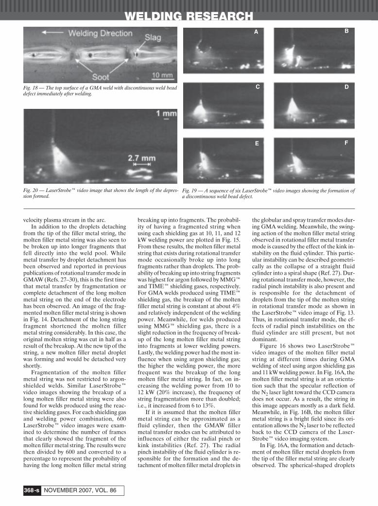
Fig. 19 — A sequence of six LaserStrobe™ video images showing the formation ofa discontinuous weld bead defect.
Fig. 20 — LaserStrobe™ video image that shows the length of the depres-sion formed.
A B
C D
FE
Nguyen Nov 2007corr layout:Layout 1 10/9/07 2:47 PM Page 368

WELDING RESEARCH
-s369WELDING JOURNAL
reflect the N2 laser light back to the CCDcamera. As a result, a bright spot on thesurface of each droplet is clearly observedin the image. Although the string is seenas a dark field because the curved surfaceof the string does not allow the reflectionof the N2 laser back to the CCD camera,there are a few visible bright spots in Fig.16A. The bright spots are simply an indi-cation that the N2 laser light is being re-flected back to the CCD camera at theselocations by specular reflections off aspherical shape similar to the molten fillermetal droplets. In other words, thesebright spots represent the swellings thatoccur along the length of the molten fillermetal string. Similar to the formation ofthe droplets, the swellings are formed byradial pinching of the molten filler metalstring into thinner necking regions. Thethinning of these necking regions will ulti-mately result in breakup of the longmolten filler metal string into fragments asseen in Fig. 14.
In Fig. 16B, a major portion of themolten filler metal string is seen as a brightfield. At this instant in time, the moltenfiller metal string had an orientation thatallowed specular reflection of the N2 laserlight back to the CCD camera. However,there are several dark segments along thebright length of the molten filler metalstring. The surface profile at the dark seg-ments must be different than the rest ofthe molten filler metal string in order tocut off the specular reflection of the N2laser light back to the CCD camera. Ifthese dark segments have a swelling or aspherical surface profile, then a brightspot similar to that observed for a dropletwould be visible. However, this is not thecase. As indicated in Fig. 16B, these darksegments occur in between the bright seg-ments of the molten filler metal string.From these observations, the dark por-tions must have pinched or necking sur-face profiles, a direct result of a radialpinch instability.
From the images in Fig. 16A, B, al-though it is not dominant, the radial pinchinstability is present during rotationaltransfer mode. In addition to producingand detaching the droplets at the tip, theradial pinch instability also causes neckingto form along the length of the moltenfiller metal string. The thinning of thesenecking regions will eventually break upthe molten filler metal string into frag-ments as seen in Fig. 14. The fragment ofthe molten filler metal string shortens themolten metal string considerably. In addi-tion to necking, the long molten fillermetal string can also be broken up intofragments as the string momentarilytouches the surface of the workpiece. Thisphenomenon is illustrated by the imagesin Fig. 17.
The LaserStrobe™ video imagesshown in Fig. 17A and B were taken ap-proximately 33 ms apart. In Fig. 17A, along molten filler metal string was vio-lently swung around with the end portionof the string about to touch the surface ofthe workpiece. In Fig. 17B, the moltenfiller metal string was broken up into twosegments. During the 33-ms time intervalbetween the first and the second images,the long molten filler metal string appar-ently touched the leading edge of the weldpool. This contact momentarily created ashort circuit, which resulted in a surge ofwelding current. Since the molten fillermetal string was in liquid form, a smallcurrent surge was needed to eliminate theshort circuiting. In the process of elimi-nating the short circuiting, the moltenfiller metal string was shattered into frag-ments as shown in Fig. 17B.
The Soot Layer
A layer of rust-colored soot was ob-served covering the bottom surface ofmany of the depressions of the discontin-uous weld bead defect. The presence of acontaminant layer can prevent moltenweld metal from refilling the gouged re-gion of the weld pool by preventing con-tact and wetting at the fusion boundary.As this could also contribute to the for-mation of the depressions that break upthe weld bead into segments, further ex-amination of the soot layer at the bottomof the depression and its effects on the for-mation of the discontinuous weld bead de-fect was undertaken.
Figure 18 shows the as-welded top sur-face of a GMA weld with the discontinu-ous weld bead defect. The surface of theworkpiece adjacent to the weld bead iscovered with a thick layer of rust-coloredsoot, while the good weld bead segmentsare relatively clean. As noted in Fig. 18,the dark spots formed on the top surfaceat the end of each good weld bead segmentwere found to be a (Mn,Si)xOy glassy slag.In addition, there was a thin layer of sootcompletely covering the bottom surface ofthe depressions of the discontinuous weldbead. The chemical composition of thesoot on the top surface of the adjacentworkpiece and the soot covering the bot-
tom surface of the depression were ana-lyzed using a LEO FESEM 1530 fieldemission scanning electron microscopeequipped with an EDX analysis system.Since the soot just covered the top surfaceof the workpiece, the scanning electronmicroscope was set at 15 keV to minimizethe interaction volume between the elec-trons and the analyzed material (Ref. 31).The small interaction volume ensured thatthe elements detected during the chemicalanalysis belonged to the soot. The ele-mental constituents of the soot coveringthe top surface of the workpiece adjacentto the weld bead were identified as Fe,Mn, Si, Zn, and oxygen. Since the ER70S-6 electrode wire has a high content of de-oxidizers such as Mn and Si (Table 1), it isnot unexpected to find these elements inthe chemical composition of the soot.During welding, it is thought that the Mnand Si from the electrode wire were va-porized inside the welding arc. As thewelding gun moved forward, the Mn andSi metal vapors oxidized and condensedon the surface of the workpiece adjacentto the weld bead. Meanwhile, as shown inFig. 18, the good weld segments were clearof any soot since the weld bead was athigher temperatures during the time pe-riod when the metal vapors condensed.
An EDX analysis was also performedon the soot layer covering the bottom sur-face of the depression — Fig. 18. Using thesame setup on the scanning electron mi-croscope, the elements detected by thisEDX analysis were Fe, Mn, Si, and oxy-gen, which are similar to those elementsfound in the rust-colored soot formed onthe surface of the workpiece adjacent tothe weld bead. From the results of thechemical analysis, the soot, which coversthe bottom surface of the depressions of adiscontinuous weld bead defect, waschemically similar to the common weldingsoot that typically forms on the coolermetal surface adjacent to the weld bead.As previously discussed, the shallow HAZsuggests that there was less sensible heatinput at the depression — Fig. 9. As a re-sult, the surface of the depression wascooler than the adjacent good segments ofthe weld bead. The Mn and Si metal va-pors condensed over the bottom surface ofthe depression just as they condensed on
Table 3 — The Voltage and the Measured Welding Current at 10, 11, and 12 kW for Argon, MMG™,and TIME™ Shielding Gases
Argon MMG™ TIME™Voltage Avg. Current Voltage Avg. Current Voltage Avg. Current
(V) (A) (V) (A) (V) (A)
10 kW 32.5 306.5 34.5 288.0 35.5 278.411 kW 33.0 326.1 35.0 315.0 36.0 306.712 kW 36.0 333.7 37.3 326.9 38.5 311.5
Nguyen Nov 2007corr layout:Layout 1 10/9/07 2:47 PM Page 369

WELDING RESEARCH
NOVEMBER 2007, VOL. 86-s370
the surface of the workpiece adjacent tothe weld bead. Since the soot layer wasproduced from the metal vapors that oxi-dized and condensed at some distance be-hind the welding arc, it was not present in-side the weld pool to prevent the moltenweld metal from refilling the gouged re-gion. Thus, the observed layer of soot isnot responsible for the formation of thedepressions in the discontinuous weldbead defect.
The Role of Rotational Transfer Mode inForming the Discontinuous Weld BeadDefect
The LaserStrobe™ video imaging sys-tem was used to observe the formation ofa discontinuous weld bead defect made at40 mm/s welding speed when usingMMG™ shielding gas, ER70S-6 electrodewire, and 10 kW welding power. Figure 19contains a sequence of six video imageseach 33 ms apart detailing the events thattook place during the formation of a dis-continuous weld bead defect. In Fig. 19A,a long molten filler metal string is clearlyvisible with the molten filler metaldroplets that are being formed, detached,and transferred to the weld pool from thetip of the string. As previously mentioned,in the rotational transfer mode regime,the radial pinch instability that acts on themolten filler metal string is responsible forthe formation and detachment of thedroplets (Ref. 27). This particular insta-bility is also capable of producing neckingat various places along the length of themolten filler metal string. In Fig. 19A, thenecking regions are seen as the dark ringsalong the length of the molten filler metalstring. The thinning of these necking re-gions will eventually break up the longmolten filler metal string into fragments asshown in Fig. 19B. With the breakup, theoriginal molten filler metal string and thearc length are shortened as compared tothose in Fig. 19A.
In Fig. 19B, the end of the detachedfragment is clearly visible above the sur-face of the weld pool while the remainingportion of the original molten filler metalstring is still attached to the solid electrodewire. However, in the 33-ms time periodbetween Fig. 19B and C, the remainingportion of the original string has brokenoff from the tip of the solid electrode wireand transferred to the weld pool. As isclearly evident in Fig. 19C, during thistime period, transfer of molten filler metalto the weld pool does not occur. In fact, anew molten filler metal droplet is begin-ning to form at the tip of the electrode inFig. 19C. With the formation of a newmolten filler metal droplet at the tip of thesolid electrode wire, the arc length is ap-parently the longest in the sequence as
compared to the arc lengths of Fig. 19Band C, respectively.
In Fig. 19C, the welding arc behaves as ifit is an autogenous welding process. As maybe seen in Fig. 19A–D, the width of the weldpool remains consistently the same. Thissuggests that the heat input from the weld-ing arc has not been influenced by thebreakup and the detachment of the longmolten filler metal string. As a result, theheat generated by the welding arc continuesto melt and to penetrate the original surfaceof the workpiece although the transfer ofmolten filler metal does not occur.
In Fig. 19D, one molten filler metaldroplet is seen momentarily before touch-ing the top surface of the weld pool. Thismay be the molten filler metal droplet,which is noted in the previous image ofFig. 19C. In the 33-ms time period be-tween Fig. 19B and C, there is a large ad-dition of molten filler metal to the weldpool due to the detachment of a longmolten filler metal string. Meanwhile, forthe same time period between Fig. 19Cand D, there is approximately one fillermetal droplet transferred to the weld pool.This is a considerable reduction in theamount of filler metal transferred. The re-duced transfer of molten filler metal mayalso extend from the Fig. 19D to Fig. 19Etime period. After the detachment of along molten filler metal string, the GMAwelding process temporarily switches backto the early stage of spray transfer mode asevidenced by the formation and the de-tachment of a molten filler metal droplet.Eventually, a new molten filler metalstring begins to form again in Fig. 19E androtational transfer mode is resumed withthe long molten filler metal string as illus-trated in Fig. 19F. For the 67-ms time pe-riod starting from Fig. 19C and ending atFig. 19E, there is a large reduction in theamount of filler metal transferred into theweld pool. During this time period, thewelding arc continued to melt and to pen-etrate the workpiece similar to an autoge-nous welding process. As a result, the de-pression of a discontinuous weld beaddefect should have the same penetrationdepth as the good weld segments. As pre-viously discussed, this was one of the ob-served geometric features of the depres-sion region of a discontinuous weld beaddefect. However, because of the reducedamount of the filler metal transferred, theHAZ at the depression is smaller com-pared to the HAZ under the good weldbead segments — Fig. 9.
At 40 mm/s welding speed and 67-mstime period, the linear distance traveledby the welding arc along the weld joint isapproximately 2.7 mm. Over this distance,the amount of filler metal transferred tothe weld pool has been drastically re-duced. There will not be enough molten
weld metal to form a proper weld beadprofile. As a result, a depression separat-ing the good weld bead segments willform. Theoretically, the length of the de-pression as measured in the welding di-rection should be approximately 2.7 mm.Figure 20 is a LaserStrobe™ video imageshowing the length of the depression thatwas formed during the sequence of imagesin Fig. 19. As indicated, the length of thedepression is approximately 2.7 mm,which is equal to the linear distance overwhich the amount of filler metal trans-ferred to the weld pool was drastically re-duced. These images suggest that incon-sistent filler metal transfer rate duringrotational transfer mode causes the for-mation of the depression in discontinuousweld bead defect.
For GMA welds produced using argonshielding gas, the discontinuous weld beaddefect did not occur at higher weldingpowers although the filler metal transfermode was rotational. One possible expla-nation is the frequent fragment detach-ments from the long molten filler metalstring with argon shielding gas as shown inFig. 15. The arc lengths of argon-shieldedGMA welds were about twice the arclengths of welds produced using the reac-tive shielding gas (Ref. 17). In addition,the surface tension of molten steel inargon shielding gas will be higher than thatin reactive shielding gases (Ref. 32). Be-cause of the long arc length and the highsurface tension, the length of the moltenfiller metal string will also be longer com-pared to those present when using reactiveshielding gases.
For each GMA weld, the voltage andthe wire feed speed were normally setprior to welding. In the present study, dur-ing welding, the current was measuredusing the previously described data-acquisition system. The voltage and theaverage welding current for differentwelding powers and shielding gas combi-nations are shown in Table 3. In general,the welds produced using argon shieldinggas had lower voltage settings, but largerwelding currents, than those producedusing the reactive shielding gases. Withhigh welding currents, the radial pinchforce would be stronger since the electro-magnetic force that generated the pinchforce is a function of the welding current(Refs. 2, 29). As a result, the detachmentsof molten filler metal droplets and moreimportantly, the fragments, occurredmore frequently for argon shielding gas — Fig. 15. With the long molten filler metalstring and the more frequent fragment de-tachments, the filler metal deposition ratewill be more consistent. In other words,the time period in which the molten fillermetal is not transferred to the weld pool isrelatively short or nonexistent. As a result,
Nguyen Nov 2007corr layout:Layout 1 10/9/07 2:48 PM Page 370

WELDING RESEARCH
-s371WELDING JOURNAL
the discontinuous weld bead defect doesnot occur at higher welding powers. In-stead, the humping phenomenon is thelimiting factor that prevents achievementof higher welding speeds.
With the higher welding powers androtational filler metal transfer, the weld-ing speeds for GMA welds produced usingreactive shielding gases are limited by theformation of the discontinuous weld beaddefect. From experimental observations,the inconsistent amount of molten fillermetal deposited during rotational transfermode is the cause of the discontinuousweld bead defect. This inconsistent fillermetal transfer rate is caused by the erraticbreakup of the long molten filler metalstring that typically exists in rotationaltransfer. After the detachment of the frag-ment, time is required for the string to re-establish. Meanwhile, at high weldingspeeds, the welding arc proceeds along theweld joint as if it is an autogenous weldingprocess. The heat generated by the auto-genous welding arc consistently maintainsthe weld width and the penetration depth.However, the lack of filler metal transferduring this time period creates a depres-sion that breaks up the otherwise goodweld bead. Consequently, the discontinu-ous weld bead defect is formed.
Conclusions
Detailed observations of the sequenceof events taking place during the forma-tion of weld bead defects during high-speed bead-on-plate gas metal arc weldingof plain carbon steel using ER70S-3 andER70S-6 electrode wires, and Ar and twodifferent reactive shielding gases havebeen made. At welding powers between 5and 9 kW, spray metal transfer occurredand the welding speed was limited by theonset of the periodic humping weld beaddefect.
For GMA welds produced with argonshielding gas, there was a small increase inthe critical welding speed at which hump-ing began as the welding power was in-creased from 5 to 9 kW. When the weldingpower was further increased from 9 to 12 kW, however, the filler metal transfermode was observed to go from streamingto swinging spray transfer and the criticalwelding speed at which humping was ob-served remained constant at about 15 mm/s.
When using the reactive shieldinggases, MMG™ and TIME™, the fillermetal transfer mode changed from sprayto rotational transfer when the weldingpower was increased above 9 kW. In thiscase, the critical welding speed of theGMA welds produced using rotationaltransfer mode and reactive shielding gaseswas defined by the onset of a new aperi-
odic high-speed weld bead defect that wasidentified and defined as a discontinuousweld bead defect. Above 9 kW weldingpower, the discontinuous weld bead de-fect always occurred at welding speedsgreater than 22 mm/s independent of thewelding power. The results indicated thatnominal wire composition did not appearto play a significant role in the formationof periodic humping or the aperiodic dis-continuous weld bead defects.
The aperiodic discontinuous weld beaddefect is distinctly different from the peri-odic humping weld bead defect and hasnever before been reported in the open lit-erature. This weld bead defect can be de-scribed as the breakup of a good GMAweld bead by the aperiodic or intermittentformation of valleys or depressions wheremelting of the base metal occurred but nofiller metal was deposited. The good weldbead segments of discontinuous weldbeads had well-rounded fusion bound-aries without the finger penetration weldpool profile characteristic of GMA weldsmade using spray transfer mode. Thisgood weld bead was broken up into seg-ments by the aperiodic occurrence offiller-metal-free depressions that werevery similar to a severely gouged autoge-nous weld bead produced using high weld-ing power but no filler metal.
The formation of the discontinuousweld bead defect has been explained asthe consequence of the inconsistent trans-fer of the molten filler metal from the elec-trode wire to the weld pool when weldingwith reactive shielding gases in rotationaltransfer mode. LaserStrobe™ video im-ages of the rotational transfer modeshowed the filler metal detaching from along molten metal string on the end of theelectrode that was violently swung aroundinside the shroud of the welding arc. Dueto the radial pinching or necking that oc-curred along the length of the moltenstring, the filler metal was transferred ei-ther as droplets or as long fragments intothe weld pool. On occasion, the longmolten filler metal string momentarilytouched the weld pool and broke up intofragments. Fragmentation or completedetachment of the molten filler metalstring during rotational transfer mode hasnot been observed or previously reportedin the open literature. This fragmentationof the long molten metal string on the endof the electrode wire temporarily disruptsthe transfer of the molten filler metal intothe weld joint. Since the welding arc ismoving forward at high welding speed, thedisruption in filler metal transfer creates adepression, a region of the weld beadwhere no filler metal has been deposited,and breaks up the normally good GMAweld bead to form the aperiodic discon-tinuous weld bead defect. The random
fragmentation of the molten metal stringon the end of the electrode during rota-tional metal transfer has not been previ-ously observed or reported.
For the GMAW process, the periodichumping weld defect and the aperiodicdiscontinuous weld bead defect limit theusable welding speed in spray and rota-tional transfer modes, respectively. Thediscontinuous weld bead defect is dis-tinctly different from humping and is thedirect result of inconsistent filler metal de-position during rotational transfer. Forthe first time, the manner in which themolten filler metal is transferred from theelectrode across the welding arc to theweld pool during the GMAW process hasbeen shown to be very influential in theformation of high-speed defects such ashumping and discontinuous weld beads.
Acknowledgments
This work was supported by NaturalSciences and Engineering ResearchCouncil of Canada (NSERC), OntarioResearch and Development ChallengeFund (ORDCF), and its partners AlcanInternational, Babcock & Wilcox, Cana-dian Liquid Air Ltd., CenterLine (Wind-sor) Ltd., John Deere, Magna Interna-tional Inc., and Ventra. Loan of roboticGMA welding equipment by LincolnElectric Co. of Canada Ltd. and Fanuc Ro-botics Canada Ltd. is gratefully acknowl-edged. The TIME™ shielding gas used inthis study was supplied by BOC Gas.
References
1. Cary, H. B. 2002. Modern Welding Tech-nology. 5th ed., Toronto, Ont., Canada: PrenticeHall Canada Inc. p. 477.
2. Welding Handbook, Vol. 1, Welding Sci-ence and Technology. 1991. 8th ed., Miami,Fla.: American Welding Society. p. 50.
3. ASM Handbook — Welding, Brazing andSoldering, Vol. 6. 1993. Davies et al. eds., Ma-terials Park, Ohio: ASM International.
4. Welding Handbook, Vol. 2, WeldingProcesses. 1991. 8th ed., Miami, Fla.: AmericanWelding Society. p. 112–116.
5. Nguyen, T. C., Weckman, D. C., Johnson,D. A., and Kerr, H. W. 2006. High speed fusionweld bead defects. Science and Technology ofWelding and Joining 11(6): 618–633.
6. Soderstrom, E., and Mendez, P. 2006.Humping mechanisms present in high speedwelding. Science and Technology of Welding andJoining 11(5): 572–579.
7. Bradstreet, B. J. 1968. Effect of surfacetension and metal flow on weld bead formation.Welding Journal 47(6): 314-s to 322-s.
8. Nishiguchi, K., Matsuyama, K., Terai, K.,and Ikeda, K. 1975. Bead formation in highspeed gas-shielded metal-arc welding. Proc. 2ndInt. Symp. of the Japan Welding Soc. on ‘Ad-vanced Welding Technology,’ Osaka, Japan.Japan Welding Society, Paper 2-2-(10).
9. Nishiguchi, K., and Matsunawa, A. Au-gust 1975. Gas metal arc welding in high pres-
Nguyen Nov 2007corr layout:Layout 1 10/9/07 2:48 PM Page 371

WELDING RESEARCH
NOVEMBER 2007, VOL. 86-s372
sure atmospheres — arc characteristics andbead formation mechanisms. Proc. 2nd Int.Symp. of the Japan Welding Soc. on ‘AdvancedWelding Technology,’ Osaka, Japan. JapanWelding Society, Paper 2-2-(5).
10. Yamamoto, T., and Shimada, W. 1975. Astudy on bead formation in high speed TIG arcwelding at low gas pressure. Proc. AdvancedWelding Technology — 2nd Int. Symp. of theJapan Welding Soc. on ‘Advanced Welding Tech-nology,’ Osaka, Japan. Japan Welding Society,Paper 2-2-(7).
11. Savage, W. F., Nippes, E. F., and Agusa,K. 1979. Effect of arc force on defect formationin GTA welding. Welding Journal 58(7): 212-s to224-s.
12. Hiramoto, S., Ohmine, M., Okuda, T.,and Shinmi, A. 1987. Deep penetration weldingwith high power CO2 laser. Proc. Int’l Conf. on‘Laser Advanced Material Processing — Scienceand Application,’ Osaka, Japan. High Temp. So-ciety of Japan and Japan Laser Processing So-ciety, pp. 157–162.
13. Albright, C. E., and Chiang, S. 1988.High-speed laser welding discontinuities. Jour-nal of Laser Applications 1(1): 18–24.
14. Tsukamoto, S., Irie, H., Inagaki, M., andHashimoto, T. 1983. Effect of focal position onhumping bead formation in electron beamwelding. Trans. of National Research Inst. forMetals 25(2): 62–67.
15. Tsukamoto, S., Irie, H., Nagaki, M., andHashimoto, T. 1984. Effect of beam current onhumping bead formation in electron beamwelding. Trans. of National Research Inst. forMetals 26(2): 133–140.
16. Tomie, M., Abe, N., and Arata, Y. 1989.Tandem electron beam welding (Report IX) —high speed tandem electron beam welding.
Trans. of Japan Welding Research Inst. 18(2):175–180.
17. Nguyen, T. C., Weckman, D. C., John-son, D. A., and Kerr, H. W. 2005. The humpingphenomenon during high-speed gas metal arcwelding. Science and Technology of Welding andJoining 10(4): 447–459.
18. Shimada, W., and Hoshinouchi, S. 1982.A study on bead formation by low pressure TIGarc and prevention of undercut bead. Journal ofJapan Welding Soc. 51(3): 280–286.
19. Mendez, P. F., and Eagar, T. W. 1998.Magnitude scaling of free surface depressionduring high current TIG arc welding. Proc. 5thInt’l Conf. Trends in Welding Research, PineMountain, Ga., J. M. Vitek, S. A. David, J. A.Johnson, H. B. Smartt, and T. DebRoy, eds., pp.13–18, Materials Park, Ohio: ASM International.
20. Mendez, P. F., and Eagar, T. W. 2001. Es-timation of the characteristic properties of theweld pool during high productivity arc welding.Proc. Mathematical Modelling of Weld Phenom-ena 5 Conf., eds. H. Cerjak and H. K. D. H.Bhadeshia, pp. 67–94, London, UK: Inst. ofMaterials.
21. Mendez, P. F., and Eagar, T. W. 2003.Penetration and defect formation in high-current arc welding. Welding Journal 82(10):296-s to 306-s.
22. Gratzke, U., Kapadia, P. D., Dowden, J.,Kross, J., and Simon, G. 1992. Theoretical ap-proach to the humping phenomenon in weldingprocesses. Journal of Physics D: Applied Physics25(11): 1640–1647.
23. Paton, E. O., Mandel’berg, S. L., andSidorenko, B. G. 1971. Certain special featuresof the formation of welds made at high speeds.Avt. Svarka 24: 1–6.
24. Nguyen, T. C. 2005. Weld Defects in High-Speed Gas Metal Arc Welding, PhD thesis. Wa-terloo, Ont., Canada: University of Waterloo.
25. LaserStrobe™ Model 4Z — OperationManual. 1999. Idaho Falls, Idaho: Control Vi-sion Inc.
26. Vander Voort, G. F. 1999. MetallographyPrinciples and Practice. Materials Park, Ohio:ASM International.
27. Ushio, M., Ikeuchi, K., Tanaka, M., andSeto, T. 1993. Effects of shielding gas composi-tion on metal transfer phenomena in high cur-rent GMA welding. Trans. Japan Welding Re-search Inst. 22(1): 7–12.
28. Lyttle, K. A. 1983. GMAW – A versatileprocess on the move. Welding Journal 62(3):15–23.
29. Lancaster, J. F. ed. 1984. The Physics ofWelding. Willowdale, Ont., Canada: PergamonPress Canada Ltd.
30. Yamamoto, H., Harada, S., and Ya-mamoto, Y. 1990. Arc characteristics and metaltransfer in high current MAG welding — effectof shielding gas composition on metal transfer.Proc. 5th JWS Int’l Symposium — AdvancedTechnology in Welding, Material Processing andEvaluation, Japan Welding Society, Tokyo,Japan. pp. 115–120.
31. Goldstein, J. I., Newbury, D. E., Echlin,P., Joy, D. C., Romig Jr., A. D., Lyman, C. E.,Fiori, C., and Lifshin, E. 1990. Scanning Elec-tron Microscopy and X-Ray Microanalysis, 2nded. New York, N.Y.: Kluwer Academic &Plenum Publishers. pp. 79–90.
32. Subramanian, S., and White, D. R. 2001.Effect of shielding gas composition on surfacetension of steel droplets in a gas-metal-arcwelding arc. Metallallurgical & Materials Trans-actions B 32B(2): 313–318.
All authors should address themselves to thefollowing questions when writing papers for submissionto the Welding Research Supplement:
◆ Why was the work done?◆ What was done?◆ What was found?◆ What is the significance of your results?◆ What are your most important conclusions?With those questions in mind, most authors can
logically organize their material along the following lines,using suitable headings and subheadings to divide thepaper.
1) Abstract. A concise summary of the major elementsof the presentation, not exceeding 200 words, to help thereader decide if the information is for him or her.
2) Introduction. A short statement giving relevantbackground, purpose, and scope to help orient the reader.Do not duplicate the abstract.
3) Experimental Procedure, Materials, Equipment.4) Results, Discussion. The facts or data obtained
and their evaluation.5) Conclusion. An evaluation and interpretation of
your results. Most often, this is what the readers remember.6) Acknowledgment, References and Appendix.Keep in mind that proper use of terms, abbreviations,
and symbols are important considerations in processing amanuscript for publication. For welding terminology, theWelding Journal adheres to AWS A3.0:2001, StandardWelding Terms and Definitions.
Papers submitted for consideration in the WeldingResearch Supplement are required to undergo PeerReview before acceptance for publication. Submit anoriginal and one copy (double-spaced, with 1-in. marginson 8 1⁄2 x 11-in. or A4 paper) of the manuscript. A manuscriptsubmission form should accompany the manuscript.
Tables and figures should be separate from themanuscript copy and only high-quality figures will bepublished. Figures should be original line art or glossyphotos. Special instructions are required if figures aresubmitted by electronic means. To receive completeinstructions and the manuscript submission form, pleasecontact the Peer Review Coordinator, Erin Adams, at (305)443-9353, ext. 275; FAX 305-443-7404; or write to theAmerican Welding Society, 550 NW LeJeune Rd., Miami,FL 33126.
Preparation of Manuscripts for Submissionto the Welding Journal Research Supplement
Nguyen Nov 2007corr layout:Layout 1 10/9/07 2:49 PM Page 372