Embed Size (px)
Citation preview

IMPLEMENTATION GUIDE
Copyright © 2009, Juniper Networks, Inc. 1
NGEN MVPN wITh P2MP LSP IMPLEMENTATION GUIDE
Although Juniper Networks has attempted to provide accurate information in this guide, Juniper Networks does not warrant or guarantee the accuracy of the information provided herein. Third party product descriptions and related technical details provided in this document are for information purposes only and such products are not supported by Juniper Networks. All information provided in this guide is provided “as is”, with all faults, and without warranty of any kind, either expressed or implied or statutory. Juniper Networks and its suppliers hereby disclaim all warranties related to this guide and the information contained herein, whether expressed or implied of statutory including, without limitation, those of merchantability, fitness for a particular purpose and noninfringement, or arising from a course of dealing, usage, or trade practice.

2 Copyright © 2009, Juniper Networks, Inc.
IMPLEMENTATION GUIDE - NGEN MVPN with P2MP LSP Implementation Guide
Table of Contents
Introduction . . . . . . . . . . . . . . . . . . . . . . . . . . . . . . . . . . . . . . . . . . . . . . . . . . . . . . . . . . . . . . . . . . . . . . . . . . . . . . . . . . . . . . . . . . . . . . . . . . . . . 4
Scope . . . . . . . . . . . . . . . . . . . . . . . . . . . . . . . . . . . . . . . . . . . . . . . . . . . . . . . . . . . . . . . . . . . . . . . . . . . . . . . . . . . . . . . . . . . . . . . . . . . . . . . . . . 4
Implementation . . . . . . . . . . . . . . . . . . . . . . . . . . . . . . . . . . . . . . . . . . . . . . . . . . . . . . . . . . . . . . . . . . . . . . . . . . . . . . . . . . . . . . . . . . . . . . . . . 4
Physical Topology . . . . . . . . . . . . . . . . . . . . . . . . . . . . . . . . . . . . . . . . . . . . . . . . . . . . . . . . . . . . . . . . . . . . . . . . . . . . . . . . . . . . . . . . . . . . . 5
hardware Used for Validation Environment . . . . . . . . . . . . . . . . . . . . . . . . . . . . . . . . . . . . . . . . . . . . . . . . . . . . . . . . . . . . . . . . . . . . . 5
Juniper Networks Equipment . . . . . . . . . . . . . . . . . . . . . . . . . . . . . . . . . . . . . . . . . . . . . . . . . . . . . . . . . . . . . . . . . . . . . . . . . . . . . . . . 5
Testing Equipment Used for Validation Environment . . . . . . . . . . . . . . . . . . . . . . . . . . . . . . . . . . . . . . . . . . . . . . . . . . . . . . . . . . 5
Software Used for Validation Environment . . . . . . . . . . . . . . . . . . . . . . . . . . . . . . . . . . . . . . . . . . . . . . . . . . . . . . . . . . . . . . . . . . . . . . 5
Configuration and Validation . . . . . . . . . . . . . . . . . . . . . . . . . . . . . . . . . . . . . . . . . . . . . . . . . . . . . . . . . . . . . . . . . . . . . . . . . . . . . . . . . . . . . 6
Logical Topology . . . . . . . . . . . . . . . . . . . . . . . . . . . . . . . . . . . . . . . . . . . . . . . . . . . . . . . . . . . . . . . . . . . . . . . . . . . . . . . . . . . . . . . . . . . . . . 6
Base Configuration before Enabling Multicast services for MPLS L3 VPN . . . . . . . . . . . . . . . . . . . . . . . . . . . . . . . . . . . . . . . . . . 6
Summary of Steps for Enabling NGEN MVPN . . . . . . . . . . . . . . . . . . . . . . . . . . . . . . . . . . . . . . . . . . . . . . . . . . . . . . . . . . . . . . . . . . . .7
Preparing Core for NGEN MVPN Service . . . . . . . . . . . . . . . . . . . . . . . . . . . . . . . . . . . . . . . . . . . . . . . . . . . . . . . . . . . . . . . . . . . . . . .7
Enabling NGEN MVPN for Individual VRFs . . . . . . . . . . . . . . . . . . . . . . . . . . . . . . . . . . . . . . . . . . . . . . . . . . . . . . . . . . . . . . . . . . . . .7
Step-by-Step Configuration . . . . . . . . . . . . . . . . . . . . . . . . . . . . . . . . . . . . . . . . . . . . . . . . . . . . . . . . . . . . . . . . . . . . . . . . . . . . . . . . . . . . .7
Step 1: Enable PIM on P and PE Routers . . . . . . . . . . . . . . . . . . . . . . . . . . . . . . . . . . . . . . . . . . . . . . . . . . . . . . . . . . . . . . . . . . . . . . .7
Step 2: Creating provider tunnels . . . . . . . . . . . . . . . . . . . . . . . . . . . . . . . . . . . . . . . . . . . . . . . . . . . . . . . . . . . . . . . . . . . . . . . . . . . . 8
Step 3: Configure inet-mvpn Address Family for IBGP Sessions on PE Routers . . . . . . . . . . . . . . . . . . . . . . . . . . . . . . . . . . 9
Step 4: Configure Customer Multicast Routing Protocol and C-RP on PE router . . . . . . . . . . . . . . . . . . . . . . . . . . . . . . . . . 9
Step 5: Enabling MVPN for Individual Service Instance per PE. . . . . . . . . . . . . . . . . . . . . . . . . . . . . . . . . . . . . . . . . . . . . . . . . .10
Step 6: Associate provider tunnels with Layer 3 VPN Service Instance . . . . . . . . . . . . . . . . . . . . . . . . . . . . . . . . . . . . . . . . . .10
Final NGEN MVPN Configuration with Inclusive Tunnel . . . . . . . . . . . . . . . . . . . . . . . . . . . . . . . . . . . . . . . . . . . . . . . . . . . . . . . . 11
Summary of the Configuration Validation . . . . . . . . . . . . . . . . . . . . . . . . . . . . . . . . . . . . . . . . . . . . . . . . . . . . . . . . . . . . . . . . . . . . . . . 17
End-to-End Traffic Flow . . . . . . . . . . . . . . . . . . . . . . . . . . . . . . . . . . . . . . . . . . . . . . . . . . . . . . . . . . . . . . . . . . . . . . . . . . . . . . . . . . . . . 17
Summary Commands for Validation of NGEN MVPN Control Plane . . . . . . . . . . . . . . . . . . . . . . . . . . . . . . . . . . . . . . . . . . . . 17
Summary Commands for Validation of NGEN MVPN Data Plane . . . . . . . . . . . . . . . . . . . . . . . . . . . . . . . . . . . . . . . . . . . . . . . 17
Detailed Validation of NGEN MVPN Control Plane . . . . . . . . . . . . . . . . . . . . . . . . . . . . . . . . . . . . . . . . . . . . . . . . . . . . . . . . . . . . . . 17
State of PE-PE IBGP Session . . . . . . . . . . . . . . . . . . . . . . . . . . . . . . . . . . . . . . . . . . . . . . . . . . . . . . . . . . . . . . . . . . . . . . . . . . . . . . . . 17
Originating a Type 1 Autodiscovery Route . . . . . . . . . . . . . . . . . . . . . . . . . . . . . . . . . . . . . . . . . . . . . . . . . . . . . . . . . . . . . . . . . . . . .19
Receiving a Type 1 AD Route . . . . . . . . . . . . . . . . . . . . . . . . . . . . . . . . . . . . . . . . . . . . . . . . . . . . . . . . . . . . . . . . . . . . . . . . . . . . . . . . .19
MVPN to Provider Tunnel Binding . . . . . . . . . . . . . . . . . . . . . . . . . . . . . . . . . . . . . . . . . . . . . . . . . . . . . . . . . . . . . . . . . . . . . . . . . . . 20
Originating a Type 5 Route . . . . . . . . . . . . . . . . . . . . . . . . . . . . . . . . . . . . . . . . . . . . . . . . . . . . . . . . . . . . . . . . . . . . . . . . . . . . . . . . . . 20
Originating a Type 7 Route . . . . . . . . . . . . . . . . . . . . . . . . . . . . . . . . . . . . . . . . . . . . . . . . . . . . . . . . . . . . . . . . . . . . . . . . . . . . . . . . . . . 21
Detailed Validation of the VPN Multicast Data Plane . . . . . . . . . . . . . . . . . . . . . . . . . . . . . . . . . . . . . . . . . . . . . . . . . . . . . . . . . . . 24
Configuration and Validation of NGEN MVPN with Selective Tunnels . . . . . . . . . . . . . . . . . . . . . . . . . . . . . . . . . . . . . . . . . . . . . . 26
Selective Tunnel Configuration . . . . . . . . . . . . . . . . . . . . . . . . . . . . . . . . . . . . . . . . . . . . . . . . . . . . . . . . . . . . . . . . . . . . . . . . . . . . . . . . 26
Configuration of the PE2 routing-instance with Selective Tunnel . . . . . . . . . . . . . . . . . . . . . . . . . . . . . . . . . . . . . . . . . . . . . . . . 27

Copyright © 2009, Juniper Networks, Inc. 3
IMPLEMENTATION GUIDE - NGEN MVPN with P2MP LSP Implementation Guide
Table of Figures
Figure 1: Network topology used for configuration . . . . . . . . . . . . . . . . . . . . . . . . . . . . . . . . . . . . . . . . . . . . . . . . . . . . . . . . . . . . . . . . . 5
Figure 2: Simplified topology for base configuration . . . . . . . . . . . . . . . . . . . . . . . . . . . . . . . . . . . . . . . . . . . . . . . . . . . . . . . . . . . . . . . 6
Figure 3: Logical topology used for configuration of NGEN MVPN with selective tunnels . . . . . . . . . . . . . . . . . . . . . . . . . . . . 26
Detailed Validation of the Control Plane of NGEN MVPN with Selective Tunnels . . . . . . . . . . . . . . . . . . . . . . . . . . . . . . . . . 28
Originating a Type 1 Route . . . . . . . . . . . . . . . . . . . . . . . . . . . . . . . . . . . . . . . . . . . . . . . . . . . . . . . . . . . . . . . . . . . . . . . . . . . . . . . . . . 28
Originating a Type 5 Route . . . . . . . . . . . . . . . . . . . . . . . . . . . . . . . . . . . . . . . . . . . . . . . . . . . . . . . . . . . . . . . . . . . . . . . . . . . . . . . . . . 29
Originating a Type 7 Route . . . . . . . . . . . . . . . . . . . . . . . . . . . . . . . . . . . . . . . . . . . . . . . . . . . . . . . . . . . . . . . . . . . . . . . . . . . . . . . . . . 30
Originating a Type 3 Route . . . . . . . . . . . . . . . . . . . . . . . . . . . . . . . . . . . . . . . . . . . . . . . . . . . . . . . . . . . . . . . . . . . . . . . . . . . . . . . . . . . 31
Originating a Type 4 Route . . . . . . . . . . . . . . . . . . . . . . . . . . . . . . . . . . . . . . . . . . . . . . . . . . . . . . . . . . . . . . . . . . . . . . . . . . . . . . . . . 32
Validation of the Data Plane of NGEN MVPN with Selective Tunnels . . . . . . . . . . . . . . . . . . . . . . . . . . . . . . . . . . . . . . . . . . . . . . . 34
Summary . . . . . . . . . . . . . . . . . . . . . . . . . . . . . . . . . . . . . . . . . . . . . . . . . . . . . . . . . . . . . . . . . . . . . . . . . . . . . . . . . . . . . . . . . . . . . . . . . . . . . . 36
About Juniper Networks . . . . . . . . . . . . . . . . . . . . . . . . . . . . . . . . . . . . . . . . . . . . . . . . . . . . . . . . . . . . . . . . . . . . . . . . . . . . . . . . . . . . . . . . . 36

4 Copyright © 2009, Juniper Networks, Inc.
IMPLEMENTATION GUIDE - NGEN MVPN with P2MP LSP Implementation Guide
Introduction
Unicast L3VPN is a commonly deployed service used by many service providers and large enterprise customers. This
service is based on RFC 2547bis, which does not have the framework for transporting of multicast traffic across the
same infrastructure. The L3VPN working group addresses this need with the procedure described in the following drafts.
draft-ietf-l3vpn-2547bis-mcast-07.txt•
ietf-l3vpn-2547bis-mcast-bgp-05.txt. •
NGEN MVPN, which is based on these drafts, adopted two important properties of unicast BGP/MPLS VPNs:
BGP protocol distributes all the necessary routing information to enable VPN multicast service. This allows Service •
Providers to leverage their knowledge and investment in managing BGP/MPLS VPN unicast service to offer VPN
multicast services.
Control plane independence from forwarding plane is provided (as required by RFC4834). This allows the separation •
of the control and data plane protocols and makes it easier to leverage newer transport technologies such as MPLS
in delivering multicast VPN service.
The configurations presented in this document are targeted for service providers and large enterprise networks. More
specifically, the configurations used to leverage and enhance existing unicast Layer 3 VPN 2547bis service offering
to offer multicast service using the same MPLS data plane and BGP control plane architecture. This reduces the
operational expenses of using the same technology used to offer for both unicast and multicast services over the same
infrastructure.
This implementation guide assists network designers and operation engineers who support service providers’ large
enterprise customers with Layer 3 VPN deployments using the Juniper Networks® M Series Multiservice Edge Routers,
T Series Core Routers, and MX Series 3D Universal Edge Routers.
Scope
RFC4364, originally RFC 2547, has not specified a mechanism to provide multicast signaling and multicast data
delivery through service provider networks for Layer 3 VPN services. Thus, a number of solutions have been discussed,
implemented, and deployed these past few years.
This configuration guide focuses on the options where BGP is used for exchanging customer multicast routes among
Provider Edge (PE) routers and RSVP-TE is used for creating multicast data tunnels through service provider core network.
Implementation
Figure 1 represents the complete view of the network topology used for this configuration guide.
Tables 1 through 3 identify the hardware and software used for the validation environment.

Copyright © 2009, Juniper Networks, Inc. 5
IMPLEMENTATION GUIDE - NGEN MVPN with P2MP LSP Implementation Guide
Physical Topology
Figure 1: Network topology used for configuration
Hardware Used for Validation Environment
Juniper Networks Equipment
Table 1: Juniper Networks Routers Used for Validation Environment
EQUIPMENT COMPONENTS
1x T320 router 1x M320 router
10 Gigabit Ethernet Xenpak with Type 3 FPCs•
2x MX480 routers
1x MX960 router
1x MX240 router
2x 40-port 1 Gigabit Ethernet Layer 2 / Layer 3 DPCs •
(DPCE-R-40GE-SFP or DPCE-R-Q-40GE-SFP)
8 SFPs •
2x 4-port 10GbE L2/L3 DPCs (DPCE-R-4XGE-XFP or DPCE-R-Q-4XGE-XFP) •
4 XFPs•
Testing Equipment Used for Validation Environment
Table 2: Testing Equipment Used for Validation Environment
EQUIPMENT COMPONENTS
Agilent N2X tester 8 x 10/100/1000Mb ports
Software Used for Validation Environment
Table 3: Software Used for Validation Environment
EQUIPMENT COMPONENTS
M Series, T Series, and MX Series routers Junos operating system release 9.1R2
MX960
M320
Source192.7.1.2
Group226.1.1.1
Source192.9.1.2
Group224.129.0.1 Receivers
Receivers
T320
M7i
M7iMX240 MX480
xe-3/1/0ge-5/1/0
ge-6/1/0ge-2/0/0
ge-1/1/0ge-6/0/0
ge-3/1/0
xe-4/1/0 ge-0/1/0
ge-8/1/0
ge-0/1/0
xe-0/1/0
xe-0/1/0
xe-0/1/0
xe-0/2/0
ge-1/1/0ge-0/0/0
ge-0/1/0
xe-0/3/0ge-1/1/0
ge-1/1/0
ge-0/1/1
xe-0/3/0
MX480
xe-0/1/0xe-0/2/0
xe-0/3/0xe-0/3/0
xe-0/2/0
xe-0/0/0
CE1 PE4
MPLS COREBGP/OSPF/RSVP
CE2
PE2PE3
PP
PE1

6 Copyright © 2009, Juniper Networks, Inc.
IMPLEMENTATION GUIDE - NGEN MVPN with P2MP LSP Implementation Guide
Configuration and Validation
Logical Topology
The topology is simplified with two PE routers and two customer edge (CE) routers for the explanation purposes. The
other PE configurations are similar with only interface naming changes required as per the router’s physical location.
Figure 2: Simplified topology for base configuration
The core network is simulated using two Juniper Networks T320 and M320 Internet routers. Four Juniper Networks
MX Series routers are connected to the T320 routers and M320 routers (used as the core router) as shown in Figure 2.
Tester ports simulate source and receivers, also as shown in Figure 2.
Base Configuration before Enabling Multicast services for MPLS L3 VPN
In the given physical topology, the following logical design is realized on Juniper Networks routers and the test
equipment prior the NGENMVPN configuration.
All interfaces in Figure 1 are configured in OSPF area 0 and traffic engineering is enabled on OSPF area 0.•
Full-mesh of point to point RSVP-TE LSP’s are configured among four PE routers for unicast L3VPN. •
One Layer 3 VPN service instance is configured.•
OSPF is enabled on all interfaces on all routers except FXP0, which is a management interface shown below. You can •
also specify individual interface names. The traffic-engineering command needs to be enabled to generate the
OPAQUE linked state advertisements LSAs ( Link State Advertisements) to build the traffic engineering database,
which are used to calculate the label switched paths (LSPs) paths. You can also configure IS-IS instead of OSPF and
add wide-metrics only to build the traffic engineering database.
A full mesh of IBGP is configured between PE routers to form the Layer 3VPN service. Initially, all IBGP sessions •
between Juniper Networks routers are configured for “inet unicast” and “inet-vpn unicast”. Using family inet-vpn
enables the multiprotocol BGP (MP-BGP) capabilities to exchange the VPNv4 routes between the PEs.
MPLS• is enabled on all core facing interfaces of PE routers and P routers.
M320
Source192.7.1.2
Group224.129.0.1
T320
M7i
M7i
Receivers
MX240
ge-5/1/0ge-2/0/0
ge-1/1/0
ge-6/0/0
ge-3/1/0ge-0/1/0
xe-0/1/0
xe-0/2/0
ge-0/0/0
ge-0/1/0
ge-1/1/0
ge-1/1/0
ge-0/1/1
MX480
xe-0/1/0
xe-0/0/0
CE1
MPLS COREBGP/OSPF/RSVP
CE2
C-RP is PE2102.255.0.1
PP
PE1
ge-0/0/0

Copyright © 2009, Juniper Networks, Inc. 7
IMPLEMENTATION GUIDE - NGEN MVPN with P2MP LSP Implementation Guide
Summary of Steps for Enabling NGEN MVPN
NGEN MVPN is enabled in two steps: 1) preparing the core for supporting tunnels used by multicast VPN services and
2) enabling individual Layer 3 VPN to provide multicast service on PE’s. however, to further clarify each comment set in
the final configuration, the enablement process is discussed in multiple steps.
The configuration statements for each step and final configuration are explained in subsequent sections.
Preparing Core for NGEN MVPN Service
Step 1:• configure RSVP, MPLS and “igp traffic-engineering” on all PE and P routers.
Step 2:• For static P2MP LSPs create provider tunnels by configuring RSVP-TE P2MP LSPs on PE routers. For
Dynamic P2MP LSPs configure the “template” parameters when dynamic LSPs are created after MVPN membership
information is obtained using MVPN auto discovery mechanisms.
Step 3:• Enable BGP for MVPN signaling by configuring the BGP inet-mvpn address family on PE routers.
Enabling NGEN MVPN for Individual VRFs
Step 4:• Enable customer multicast protocol by configuring C-multicast routing protocol on PE and CE routers
(PIM or IGMP).
Step 5:• Enable MVPN on a given Layer 3 VPN instance by configuring the mvpn protocol under the VRF on PE routers.
Step 6: • Associate provider tunnels with Layer 3 VPN service instance by configuration the “provider-tunnel”
Notes: To prepare the service provider core for point-to-multipoint (P2MP) LSP signaling, repeat step 1 on all PE and
P routers. In case the core is already enabled for traffic engineering, which is the case for most deployments, you may
omit this step.
In the case of static P2MP LSPs, repeat step 2 on all PE routers and perform “commit” after step 2 to validate the
tunnel function before enabling NGEN MVPN. In case the Dynamic P2MP LSP (lsp-template) is used, the P2MP LSP
would not function until it is associated with an MVPN instance at STEP6 and membership information is obtained.
Repeat step 3 on all of the PE routers where MVPN must be enabled. This step is a common configuration for all the
MVPN service instances; complete it in a maintenance window since a new address family would reset BGP sessions.
The alternate option could be deploying a Separate route-reflector(s) for MVPN. All the PE routers supporting MVPN
can peer with new route reflector(s) dedicated for MVPN, leaving existing BGP peers intact. In this case, it is not
necessary to complete step three within a maintenance window. This is no longer required because there is no need to
enable a new address family on the existing BGP session, or reset these MVPN sessions.
Step-by-Step Configuration
This section provides step-by-step configurations to enable NGEN multicast configurations on top of the MPLS Layer 3
VPN configurations.
Step 1: Enable PIM on P and PE Routers
This configuration step is not related to the enablement of NGEN MVPN; rather it is a general configuration to enable
traffic engineering in the core. In this simulation lab, MPLS traffic engineering previously was enabled for MPLS Layer 3
VPN services; hence, it is not required for the simulated topology. The bold text in the following configuration example
represents the minimum configuration required to enable MPLS traffic engineering in the core. The configuration should
be performed on all P and PE routers.
protocols {…truncated… rsvp { interface all { } interface fxp0.0 { disable;
8 Copyright © 2009, Juniper Networks, Inc.
IMPLEMENTATION GUIDE - NGEN MVPN with P2MP LSP Implementation Guide
} }…truncated… mpls { interface all; interface fxp0.0 { disable; } } …truncated… ospf { traffic-engineering; area 0.0.0.0 { interface fxp0.0 { disable; } interface all { } } }
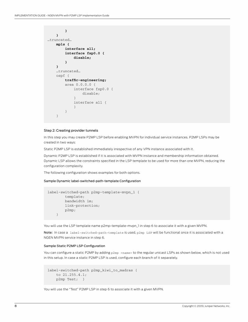
Step 2: Creating provider tunnels
In this step you may create P2MP LSP before enabling MVPN for individual service instances. P2MP LSPs may be
created in two ways:
Static P2MP LSP is established immediately irrespective of any VPN instance associated with it.
Dynamic P2MP LSP is established if it is associated with MVPN instance and membership information obtained.
Dynamic LSP allows the constraints specified in the LSP template to be used for more than one MVPN, reducing the
configuration complexity.
The following configuration shows examples for both options.
Sample Dynamic label-switched-path-template Configuration
label-switched-path p2mp-template-mvpn_1 { template; bandwidth 1m; link-protection; p2mp; }
label-switched-path p2mp_kiwi_to_madras { to 21.255.4.1; p2mp Test; }
You will use the LSP template name p2mp-template-mvpn_1 in step 6 to associate it with a given MVPN.
Note: In case a label-switched-path-template is used, p2mp LSP will be functional once it is associated with a
NGEN MVPN service instance in step 6.
Sample Static P2MP LSP Configuration
You can configure a static P2MP by adding p2mp <name> to the regular unicast LSPs as shown below, which is not used
in this setup. In case a static P2MP LSP is used, configure each branch of it separately.
You will use the “Test” P2MP LSP in step 6 to associate it with a given MVPN.

Copyright © 2009, Juniper Networks, Inc. 9
IMPLEMENTATION GUIDE - NGEN MVPN with P2MP LSP Implementation Guide
Step 3: Configure inet-mvpn Address Family for IBGP Sessions on PE Routers
Configuring the inet-mvpn address family allows PEs to enhance BGP capability to support multicast extensions
to automatically discover MVPN membership information (autodiscovery) and exchange customer multicast routes
without requiring full-mesh PIM adjacency among PE routers. This step prepares the infrastructure for individual VPNs
to function once the MVPN service is enabled on them.
Perform this configuration on all PE routers.•
This configuration resets the existing BGP session if any already being used for L3VPN service.•
Deploying a Separate route-reflector for MVPN in the network, will avoid the BGP reset, so all the PE’s supporting
MVPN can peer with MVPN route reflector. This does not change the existing L3VPN BGP infrastructure, while still able
to enable the BGP for NGEN MVPN support.
bgp { group mesh { type internal; local-address 21.255.2.1; …truncated… family inet-mvpn { signaling; } …truncated… }
Step 4: Configure Customer Multicast Routing Protocol and C-RP on PE router
This configuration allows PE routers to exchange routing information with CE routers. Since Layer 3 VPNs are mostly
deployed such that customers use a Layer 3 router for a service provider connection, PIM is mostly used for the CE-PE
multicast routing protocol. however, in some cases customers may want to use IGMP, which is supported by Junos®
operating system and is used for customer signaling protocols in a NGEN MVPN instance. The following configuration
enables PIM on a VPN for a customer-facing interface and configuration for C-RP.
If we want to configure CE router as C-RP, we need to enable MSDP or anycast-RP between the CE and PE routers so
that the source information is communicated between PE and CE (C-RP). This scenario has not been validated in
this document.
routing-instances {
l3vpn_50001 { instance-type vrf; …truncated… protocols { …truncated… pim { rp { local { address 102.255.0.1; } } interface all { mode sparse; } } …truncated…

10 Copyright © 2009, Juniper Networks, Inc.
IMPLEMENTATION GUIDE - NGEN MVPN with P2MP LSP Implementation Guide
Although it is not used in this setup, following is a sample IGMP configuration.
routing-instances { l3vpn_50001 { instance-type vrf; …truncated… protocols { Igmp { interface ge-8/1/0.1 { static { group 224.129.0.1 { source 192.9.1.2; } }}
Step 5: Enabling MVPN for Individual Service Instance per PE
This step enables the MVPN on all PE routers Layer 3 VPN service instances. This configuration sets the policies to
correctly identify and process various BGP advertisements for the building of the multicast routing table.
Step 6: Associate provider tunnels with Layer 3 VPN Service Instance
As the last step, associate a P2MP LSP tunnel with a Layer 3 VPN service, which in turn, enables you to offer NGEN
MVPN services. This configuration looks different, depends on following options:
Inclusive or selective tunnel•
Static or dynamic (• label-switched-path-template) tunnel
Note: “label-switched-path-template” can only be used with Dynamic Tunnel
The following configuration provides an inclusive dynamic tunnel associated with a particular service instance using a
P2MP label-switched-path-template.
routing-instances { l3vpn_50001 { instance-type vrf; …truncated… protocols { …truncated… mvpn { …truncated…
…truncated…routing-instances { l3vpn_50001 { instance-type vrf; interface ge-1/1/0.1; interface lo0.1; route-distinguisher 21.255.3.1:50001; provider-tunnel { rsvp-te { label-switched-path-template { p2mp-template-mvpn_1;

Copyright © 2009, Juniper Networks, Inc. 11
IMPLEMENTATION GUIDE - NGEN MVPN with P2MP LSP Implementation Guide
PE1 CONFIGURATION (THE PE THAT SERVES
THE SITES WHICH HAS ONE OR MORE SENDER)
Chassis Configuration
chassis { fpc 1 { pic 1 { tunnel-services { bandwidth 1g; } } }}
PE2 CONFIGURATION (THE PE THAT SERVES THE
SITES WHICH DOESN’T HAVE ANY SENDER)
Chassis Configuration
Not required for receiver site
} } } vrf-target target:100:50001; vrf-table-label; …truncated…
You may perform this configuration only on the PE routers that are connected to the senders if it is known that given sites
include the multicast source. If all sites have receiver and sender, this configuration must be repeated for all PE routers.
Final NGEN MVPN Configuration with Inclusive Tunnel
The following configuration includes base and new MVPN configurations once all the steps for MVPN have been
completed. The ‘bold’ text below shows the configuration that has been added to enable MVPN top of base
configuration. The configuration presented here does not include sender-site and receive site differentiation and
applicable for all the cases. A provider-tunnel configuration is used only on the PE that serves the site which is known
a priori to have (multicast) senders. The sites which are known a priori to have no (multicast) senders in our topology
hasn’t been associated with provider tunnel since The association is not required for the operation of NGEN MVPN. For
the cases where it is not known a priori whether the site contains senders, one need to configure provider tunnel on the
PE connected to that site.
If the above configuration had been replaced with a static LSP, the configuration would look like following.
…truncated…routing-instances { l3vpn_50001 { instance-type vrf; interface ge-1/1/0.1; interface lo0.1; route-distinguisher 21.255.3.1:50001; provider-tunnel { rsvp-te { static-lsp lsp-name; } } vrf-target target:100:50001; vrf-table-label; …truncated…

12 Copyright © 2009, Juniper Networks, Inc.
IMPLEMENTATION GUIDE - NGEN MVPN with P2MP LSP Implementation Guide
PE1 CONFIGURATION (THE PE THAT SERVES
THE SITES WHICH HAS ONE OR MORE SENDER)
Interface Configuration
Core Facing Interfaces
interfaces { xe-0/0/0 { unit 0 { family inet { address 21.0.3.2/30; } family mpls; } } xe-0/1/0 { unit 0 { family inet { address 21.0.3.6/30; } family mpls; } } xe-0/2/0 { unit 0 { family inet { address 21.3.5.1/30; } family mpls; } } xe-0/3/0 { unit 0 { family inet { address 21.3.4.1/30; } family mpls; } }
PE-CE Interface
ge-1/1/0 { vlan-tagging; unit 1 { vlan-id 1; family inet { address 103.41.0.1/30; } } }
Loopback Interface
lo0 { unit 0 { family inet { address 21.255.3.1/32; } }
PE2 CONFIGURATION (THE PE THAT SERVES THE
SITES WHICH DOESN’T HAVE ANY SENDER)
Interface Configuration :
Core Facing Interfaces:
interfaces { xe-0/0/0 { unit 0 { family inet { address 21.2.5.1/30; } family mpls; } } xe-0/1/0 { unit 0 { family inet { address 21.2.5.5/30; } family mpls; } } xe-0/2/0 { unit 0 { family inet { address 21.0.2.2/30; } family mpls; } } xe-0/3/0 { unit 0 { family inet { address 21.1.2.2/30; } family mpls; } }
PE-CE Interface
ge-1/1/0 { vlan-tagging; unit 1 { vlan-id 1; family inet { address 40.40.40.1/30; } } }
Loopback Interface
lo0 { unit 0 { family inet { address 21.255.2.1/32; } }

Copyright © 2009, Juniper Networks, Inc. 13
IMPLEMENTATION GUIDE - NGEN MVPN with P2MP LSP Implementation Guide
PE1 CONFIGURATION (THE PE THAT SERVES
THE SITES WHICH HAS ONE OR MORE SENDER)
Loopback Interface (cont.)
unit 1 { family inet { address 103.255.0.1/32; } } }}
Routing and Forwarding Options
routing-options { router-id 21.255.3.1; autonomous-system 100; forwarding-table { export pplb; }}
Protocols
protocols {
Step 1
rsvp { interface all { aggregate; reliable; link-protection; } interface fxp0.0 { disable; } } mpls { label-switched-path r3r2_uni_1 { to 21.255.2.1; node-link-protection; primary r3r2_uni_1; } label-switched-path r3r1_uni_1 { to 21.255.1.1; node-link-protection; primary r3r1_uni_1; } label-switched-path r3r4_uni_1 { to 21.255.4.1; node-link-protection; }
PE2 CONFIGURATION (THE PE THAT SERVES THE
SITES WHICH DOESN’T HAVE ANY SENDER)
Loopback Interface (cont.)
Loopback for Service Instance
unit 1 { family inet { address 102.255.0.1/32; } } }}
Routing and Forwarding Options
routing-options { router-id 21.255.2.1; autonomous-system 100; forwarding-table { export pplb; }}
Protocols
protocols {
Step 1
rsvp { interface all { aggregate; reliable; link-protection; } interface fxp0.0 { disable; } } mpls { label-switched-path r2r1_uni_1 { to 21.255.1.1; node-link-protection; primary r2r1_uni_1; } label-switched-path r2r3_uni_1 { to 21.255.3.1; node-link-protection; primary r2r3_uni_1; } label-switched-path r2r4_uni_1 { to 21.255.4.1; node-link-protection; }

14 Copyright © 2009, Juniper Networks, Inc.
IMPLEMENTATION GUIDE - NGEN MVPN with P2MP LSP Implementation Guide
PE1 CONFIGURATION (THE PE THAT SERVES THE
SITES WHICH HAS ONE OR MORE SENDER)
Protocols (cont.)
Step 2
label-switched-path p2mp- template-mvpn_1 { template; bandwidth 1m; link-protection; p2mp; } label-switched-path p2mp- template-mvpn_2 { template; bandwidth 10m; link-protection; p2mp; } interface all; interface fxp0.0 { disable; } } bgp { group mesh { type internal; local-address 21.255.3.1; family inet { unicast; } family inet-vpn { unicast; }
Step 3
family inet-mvpn { signaling; } include-mp-next-hop; neighbor 21.255.0.1; neighbor 21.255.5.1; neighbor 21.255.2.1; neighbor 21.255.1.1; neighbor 21.255.4.1; } } ospf { traffic-engineering; area 0.0.0.0 { interface fxp0.0 { disable; } interface all { } } }}
PE2 CONFIGURATION (THE PE THAT SERVES THE
SITES WHICH DOESN’T HAVE ANY SENDER)
Protocols (cont.)
interface all; interface fxp0.0 { disable; } } bgp { group mesh { type internal; local-address 21.255.2.1; family inet { unicast; } family inet-vpn { unicast; }
Step 3
family inet-mvpn { signaling; } include-mp-next-hop; neighbor 21.255.0.1; neighbor 21.255.5.1; neighbor 21.255.1.1; neighbor 21.255.3.1; neighbor 21.255.4.1; } } ospf { traffic-engineering; area 0.0.0.0 { interface all { } interface fxp0.0 { disable; } } }}

Copyright © 2009, Juniper Networks, Inc. 15
IMPLEMENTATION GUIDE - NGEN MVPN with P2MP LSP Implementation Guide
PE1 CONFIGURATION (THE PE THAT SERVES THE
SITES WHICH HAS ONE OR MORE SENDER)
Policies
policy-options { policy-statement pplb { then { load-balance per-packet; } }}
Service Instances
routing-instances { l3vpn_50001 { instance-type vrf; interface ge-1/1/0.1; interface lo0.1; route-distinguisher 21.255.3.1:50001;
Step 6
provider-tunnel { rsvp-te { label-switched-path- template { p2mp-template-mvpn_1; } } }
vrf-target target:100:50001; vrf-table-label; protocols { bgp { group l3vpn_50001 { neighbor 103.41.0.2 { peer-as 50001; } } }
Step 4
pim { rp { static { address 102.255.0.1; } } interface all { mode sparse; } }
Step 5
mvpn ; } }}
PE2 CONFIGURATION (THE PE THAT SERVES THE
SITES WHICH DOESN’T HAVE ANY SENDER)
Policies
policy-options { policy-statement pplb { then { load-balance per-packet; } }}
Service Instances
routing-instances { l3vpn_50001 { instance-type vrf; interface ge-1/1/0.1; interface lo0.1; route-distinguisher 21.255.2.1:50001;
## NO Provider tunnel Configuration for Receiver Site
vrf-target target:100:50001; vrf-table-label; protocols { bgp { group l3vpn_50001 { neighbor 40.40.40.2 { peer-as 50001; } } }
Step 4
pim { rp { local { address 102.255.0.1; } } interface all { mode sparse; } }
Step 5
mvpn ; } }}

16 Copyright © 2009, Juniper Networks, Inc.
IMPLEMENTATION GUIDE - NGEN MVPN with P2MP LSP Implementation Guide
CE1 Configuration
interfaces { ge-0/0/0 { unit 0 { family inet { address 192.9.1.1/24; } } } ge-0/1/0 { vlan-tagging; unit 1 { vlan-id 1; family inet { address 103.41.0.2/30; } } }}routing-options { autonomous-system 50001;}protocols { igmp { interface ge-0/0/0.0; interface ge-0/1/0.1; } bgp { group skoda { neighbor 103.41.0.1 { peer-as 100; as-override; } } } pim { rp { static { address 102.255.0.1; } } interface ge-0/0/0.0; interface ge-0/1/0.0; interface ge-0/1/0.1; }}
CE2 Configuration
interfaces { ge-5/0/0 { unit 0 { family inet { address 192.7.1.1/24; } } } ge-5/0/1 { vlan-tagging; unit 1 { vlan-id 1; family inet { address 40.40.40.2/30; } } }}routing-options { autonomous-system 50001;}protocols { bgp { group scorpio { neighbor 40.40.40.1 { peer-as 100; } } } pim { rp { static { address 102.255.0.1; } } interface ge-0/0/0.0; interface ge-5/0/1.1; }}

Copyright © 2009, Juniper Networks, Inc. 17
IMPLEMENTATION GUIDE - NGEN MVPN with P2MP LSP Implementation Guide
Summary of the Configuration Validation
End-to-End Traffic Flow
The VPN multicast source 192.9.1.2 at CE1 (tester port) is delivering multicast data to the IGMP receiver at CE2. Static
IGMP joins are created on PE3 and PE4 for this group; therefore, they are also receiving the multicast stream from the
same source as shown in the following output.
Summary Commands for Validation of NGEN MVPN Control Plane
Assume that the source 192.9.1.2 has started transmitting data to group 224.129.0.1, and the receiver connected to CE2
sent a join (*, 224.129.0.1) to PE2.
lab@PE1# run show bgp summary lab@PE1> show route table l3vpn_50001.mvpn.0 detail lab@PE1> show mvpn instance l3vpn_50001 extensive lab@PE1 > show pim mdt instance l3vpn_50001lab@PE1 > show interfaces mt* lab@PE1 > show route table l3vpn_50001.mvpn.0 detail | find 5: lab@PE2> show route table l3vpn_50001.mvpn.0 detail | find 5: lab@PE2> show route table bgp.mvpn.0 detail lab@PE2> show pim join extensive instance l3vpn_50001 lab@PE2> show igmp statisticslab@PE2> show mvpn neighbor lab@PE2> show mvpn c-multicast
Summary Commands for Validation of NGEN MVPN Data Plane
lab@PE2> show route table l3vpn_50001.inet.1 detail lab@PE2>show route forwarding-table multicast destination 224.129.0.1 extensive vpn l3vpn_50001 lab@PE2> show multicast next-hopslab@PE2> show multicast route extensive instance l3vpn_50001lab@PE2> show mpls lsp p2mp
Detailed Validation of NGEN MVPN Control Plane
State of PE-PE IBGP Session
The IBGP session between PE routers must be operational before the PE routers can exchange any MVPN route. If the
BGP session is working correctly, using the show bgp summary coming on each PE shows the bgp.l3vpn.0 and bgp.
mvpn.0 tables.
lab@PE1> show bgp summary Groups: 2 Peers: 6 Down peers: 0Table Tot Paths Act Paths Suppressed History Damp State Pendinginet.0 0 0 0 0 0 0bgp.l3vpn.0 12 8 0 0 0 0bgp.mvpn.0 7 5 0 0 0 0

18 Copyright © 2009, Juniper Networks, Inc.
IMPLEMENTATION GUIDE - NGEN MVPN with P2MP LSP Implementation Guide
Peer AS InPkt OutPkt OutQ Flaps Last Up/Dwn State|#Active/ Received/Damped...21.255.0.1 100 2275 2279 0 0 17:17:55 Establ inet.0: 0/0/0 bgp.l3vpn.0: 0/0/0 bgp.mvpn.0: 0/0/021.255.1.1 100 2282 2277 0 0 17:17:43 Establ inet.0: 0/0/0 bgp.l3vpn.0: 0/4/0 bgp.mvpn.0: 1/2/0 l3vpn_50001.inet.0: 0/4/0 l3vpn_50001.mvpn.0: 1/2/021.255.2.1 100 2278 2277 0 0 17:17:47 Establ inet.0: 0/0/0 bgp.l3vpn.0: 4/4/0 bgp.mvpn.0: 3/3/0 l3vpn_50001.inet.0: 4/4/0 l3vpn_50001.mvpn.0: 2/3/021.255.4.1 100 2285 2277 0 0 17:17:39 Establ inet.0: 0/0/0 bgp.l3vpn.0: 4/4/0 bgp.mvpn.0: 1/2/0 l3vpn_50001.inet.0: 4/4/0 l3vpn_50001.mvpn.0: 1/2/021.255.5.1 100 2280 2277 0 0 17:17:51 Establ inet.0: 0/0/0 bgp.l3vpn.0: 0/0/0 bgp.mvpn.0: 0/0/0
lab@PE2> show bgp summary Groups: 2 Peers: 6 Down peers: 0Table Tot Paths Act Paths Suppressed History Damp State Pendinginet.0 0 0 0 0 0 0bgp.l3vpn.0 13 13 0 0 0 0bgp.mvpn.0 3 3 0 0 0 0Peer AS InPkt OutPkt OutQ Flaps Last Up/Dwn State|#Active/ Received/Damped...21.255.0.1 100 2280 2284 0 0 17:19:44 Establ inet.0: 0/0/0 bgp.l3vpn.0: 0/0/0 bgp.mvpn.0: 0/0/021.255.1.1 100 2287 2284 0 0 17:19:36 Establ inet.0: 0/0/0 bgp.l3vpn.0: 4/4/0 bgp.mvpn.0: 1/1/0 l3vpn_50001.inet.0: 4/4/0 l3vpn_50001.mvpn.0: 1/1/021.255.3.1 100 2281 2285 0 0 17:19:51 Establ inet.0: 0/0/0 bgp.l3vpn.0: 5/5/0 bgp.mvpn.0: 1/1/0 l3vpn_50001.inet.0: 5/5/0 l3vpn_50001.mvpn.0: 1/1/021.255.4.1 100 2289 2283 0 0 17:19:28 Establ inet.0: 0/0/0 bgp.l3vpn.0: 4/4/0 bgp.mvpn.0: 1/1/0 l3vpn_50001.inet.0: 4/4/0 l3vpn_50001.mvpn.0: 1/1/0

Copyright © 2009, Juniper Networks, Inc. 19
IMPLEMENTATION GUIDE - NGEN MVPN with P2MP LSP Implementation Guide
Originating a Type 1 Autodiscovery Route
A NGEN MVPN PE must originate a local autodiscovery (AD) route, which means the PE routers must install a local AD
route in the L3VPN_50001.mvpn.0 table and advertise the local AD routes to each other. This route is used to find other
PEs that have sites of the same MVPN connected to them.
The AD routes should look like the following output. The loopback IP of this PE1 router is 21.255.3.1, so the AD route
that PE1 announces to the other entire PEs in the network has 21.255.3.1 as its next hop. All PEs in the network advertise
this route if they have a MVPN site configured on them.
lab@PE1> show route table l3vpn_50001.mvpn.0 detaill3vpn_50001.mvpn.0: 6 destinations, 9 routes (6 active, 1 holddown, 0 hidden)1:21.255.3.1:50001:21.255.3.1/240 (1 entry, 1 announced) *MVPN Preference: 70 Next hop type: Indirect Next-hop reference count: 2 Protocol next hop: 21.255.3.1 Indirect next hop: 0 - State: <Active Int Ext> Age: 1w0d 22:58:14 Metric2: 1 Task: mvpn global task Announcement bits (3): 0-PIM.l3vpn_50001 1-mvpn global task 2-BGP RT Background AS path: I
Receiving a Type 1 AD Route
The AD route originated from PE1 is received on PE2 and other PE routers, indicating there is an MVPN site present on
PE1. The P2MP LSP forms an LSP rooted at PE1 with other PEs as the leaf nodes.
lab@PE2> show route table l3vpn_50001.mvpn.0 detail
l3vpn_50001.mvpn.0: 7 destinations, 8 routes (7 active, 1 holddown, 0 hidden)1:21.255.3.1:50001:21.255.3.1/240 (1 entry, 1 announced) *BGP Preference: 170/-101 PMSI: Flags 0:RSVP- TE:label[0:0:0]:Session_13[21.255.3.1:0:12607:21.255.3.1] Next hop type: Indirect Next-hop reference count: 2 Source: 21.255.3.1 Protocol next hop: 21.255.3.1 Indirect next hop: 2 no-forward State: <Secondary Active Int Ext> Local AS: 100 Peer AS: 100 Age: 34:15 Metric2: 2 Task: BGP_100.21.255.3.1+54757 Announcement bits (2): 0-PIM.l3vpn_50001 1-mvpn global task AS path: I Communities: target: 100:50001 Localpref: 100 Router ID: 21.255.3.1 Primary Routing Table bgp.mvpn.0
21.255.5.1 100 2283 2284 0 0 17:19:40 Establ inet.0: 0/0/0 bgp.l3vpn.0: 0/0/0bgp.mvpn.0: 0/0/0
PE2 receives PE1’s AD route with the PMSI attribute. Both routers advertise AD routes with the unicast import RT of 100:50001.

20 Copyright © 2009, Juniper Networks, Inc.
IMPLEMENTATION GUIDE - NGEN MVPN with P2MP LSP Implementation Guide
MVPN to Provider Tunnel Binding
The state of provider tunnel binding to an MVPN can be verified by issuing the show mvpn instance command. The
output shows MVPN module’s view of the tunnel binding.
This output shows that PE1 established a provider tunnel using RSVP-TE with all other PEs in the network.
Originating a Type 5 Route
As soon as the source within the site connected to PE1 starts sending multicast data, the PIM Designated Router
connected to the source originates C-PIM Register message and sends it to the C-RP, which is PE2 (as the PE2
l3vpn_50001 instance is configured as the C-RP). As result, PE2 must originate a type 5 (source active) SA route
upon receiving the first data packet or the C-PIM register messages:
lab@PE2> show route table l3vpn_50001.mvpn.0 detail | find 5: 5:21.255.2.1:50001:32:192.9.1.2:32:224.129.0.1/240 (1 entry, 1 announced) *PIM Preference: 105 Next hop type: Multicast (IPv4) Next-hop reference count: 8 State: <Active Int> Age: 2:07:43 Task: PIM.l3vpn_50001 Announcement bits (2): 1-mvpn global task 2-BGP RT Background AS path: I
The route is installed by protocol MVPN in l3vpn_50001 instance. Then, PE2 advertises the Source-Active (SA) route to
PE1 and other PEs.
lab@PE2> show route advertising-protocol bgp 21.255.3.1 table l3vpn_50001 detail
l3vpn_50001.mvpn.0: 7 destinations, 8 routes (7 active, 1 holddown, 0 hidden)* 5:21.255.2.1:50001:32:192.9.1.2:32:224.129.0.1/240 (1 entry, 1 announced) BGP group mesh type Internal Route Distinguisher: 21.255.2.1:50001 Nexthop: Self Flags: Nexthop Change Localpref: 100 AS path: [100] I Communities: target:100:50001
Note that the SA route is advertised with the unicast import RT of 100:50001 just like the AD route.
lab@PE1> show mvpn instance extensive MVPN instance:
Legend for provider tunnelI-P-tnl -- inclusive provider tunnel S-P-tnl -- selective provider tunnel
Legend for c-multicast routes properties (Pr)DS -- derived from (*, c-g) RM -- remote VPN routeInstance: l3vpn_50001 Provider tunnel: I-P-tnl:RSVP-TE P2MP:21.255.3.1, 12607,21.255.3.1 Neighbor I-P-tnl 21.255.1.1 RSVP-TE P2MP:21.255.1.1, 2238,21.255.1.1 21.255.2.1 RSVP-TE P2MP:21.255.2.1, 39195,21.255.2.1 21.255.4.1 RSVP-TE P2MP:21.255.4.1, 63012,21.255.4.1 C-mcast IPv4 (S:G) Ptnl St 192.9.1.2/32:224.129.0.1/32 RSVP-TE P2MP:21.255.3.1, 12607,21.255.3.1 RM

Copyright © 2009, Juniper Networks, Inc. 21
IMPLEMENTATION GUIDE - NGEN MVPN with P2MP LSP Implementation Guide
lab@PE1> show route table bgp.mvpn.0 detail bgp.mvpn.0: 5 destinations, 7 routes (5 active, 0 holddown, 0 hidden)5:21.255.2.1:50001:32:192.9.1.2:32:224.129.0.1/240 (1 entry, 0 announced) *BGP Preference: 170/-101 Next hop type: Indirect Next-hop reference count: 6 Source: 21.255.2.1 Protocol next hop: 21.255.2.1 Indirect next hop: 2 no-forward State: <Active Int Ext> Local AS: 100 Peer AS: 100 Age: 2:25:32 Metric2: 2 Task: BGP_100.21.255.2.1+179 AS path: I Communities: target:100:50001 Localpref: 100 Router ID: 21.255.2.1 Secondary Tables: l3vpn_50001.mvpn.0
Note that the Secondary Tables field is set to L3VPN_50001.mvpn.0 indicating that the route is also installed in
L3VPN_50001.mvpn.0 table.
The route entry for the SA route in L3VPN_50001.mvpn.0 table looks like the following.
lab@PE1> show route table l3vpn_50001.mvpn.0 detail | find 5:5:21.255.2.1:50001:32:192.9.1.2:32:224.129.0.1/240 (1 entry, 1 announced) *BGP Preference: 170/-101 Next hop type: Indirect Next-hop reference count: 6 Source: 21.255.2.1 Protocol next hop: 21.255.2.1 Indirect next hop: 2 no-forward State: <Secondary Active Int Ext> Local AS: 100 Peer AS: 100 Age: 2:25:23 Metric2: 2 Task: BGP_100.21.255.2.1+179 Announcement bits (2): 0-PIM.l3vpn_50001 1-mvpn global task AS path: I Communities: target:100:50001 Localpref: 100 Router ID: 21.255.2.1 Primary Routing Table bgp.mvpn.0
Originating a Type 7 Route
Since PE2 is C-RP, it learns the IP address of the source sending data to group 224.129.0.1 using the register messages
sent from the CE1..PE2 advertises this source active information to other PEs using SA route. Now that PE2 also knows
that there is a local receiver and the source is reachable via MVPN, PE2 originates a Source Tree Join (type 7) route and
installs it in the L3VPN_50001.mvpn.0 table.
lab@PE2> show route table l3vpn_50001.mvpn.0 detail l3vpn_50001.mvpn.0: 7 destinations, 8 routes (7 active, 1 holddown, 0 hidden)7:21.255.3.1:50001:100:32:192.9.1.2:32:224.129.0.1/240 (2 entries, 2 announced)
PE1 should install the route in the bgp.mvpn.0 table first and then in L3VPN_50001.mvpn.0 table assuming the route is
accepted by the VRF import policy:

22 Copyright © 2009, Juniper Networks, Inc.
IMPLEMENTATION GUIDE - NGEN MVPN with P2MP LSP Implementation Guide
*MVPN Preference: 70 Next hop type: Indirect Next-hop reference count: 3 Protocol next hop: 21.255.2.1 Indirect next hop: 0 - State: <Active Int Ext> Age: 4:50:08 Metric2: 1 Task: mvpn global task Announcement bits (3): 0-PIM.l3vpn_50001 1-mvpn global task 2-BGP RT Background AS path: I Communities: target:21.255.3.1:3 PIM Preference: 105 Next hop type: Multicast (IPv4), Next hop index: 1048580 Next-hop reference count: 5 State: <Int> Inactive reason: Route Preference Age: 21:54:16 Task: PIM.l3vpn_50001 Announcement bits (1): 1-mvpn global task AS path: I Communities: target:21.255.3.1:3
There are two protocols installing the type 7 route PIM and MVPN in the L3VPN_50001.mvpn.0 table. Since MVPN has a
better route preference (70) then the PIM protocol (105), the MVPN route seems active and the PIM route seems inactive
The state in the PIM join after the Type 5 SA and Type 7 C-mcast routes originated from PE2
lab@PE2> show pim join extensive instance l3vpn_50001 Instance: PIM.l3vpn_50001 Family: INET
Group: 224.129.0.1 Source: * RP: 102.255.0.1 Flags: sparse,rptree,wildcard Upstream interface: Local Upstream neighbor: Local Upstream state: Local RP Downstream neighbors: Interface: ge-1/1/0.1 102.21.0.2 State: Join Flags: SRW Timeout: 189
Group: 224.129.0.1 Source: 192.9.1.2 Flags: sparse Upstream protcol: BGP Upstream interface: Through BGP Upstream neighbor: Through MVPN Upstream state: Local RP, Join to Source Keepalive timeout: 62 Downstream neighbors: Interface: ge-1/1/0.1 102.21.0.2 State: Join Flags: S Timeout: 189
Instance: PIM.l3vpn_50001 Family: INET6
The first state is created when the original (*, 224.129.0.1) was received and the type 6 route was installed. The second
one is created after the SA route(Type 5) and C-Multicast route (Type 7) was originated by PE2

Copyright © 2009, Juniper Networks, Inc. 23
IMPLEMENTATION GUIDE - NGEN MVPN with P2MP LSP Implementation Guide
lab@PE1> show policy Configured policies:__vrf-mvpn-import-cmcast-l3vpn_50001-internal____vrf-mvpn-import-cmcast-leafAD-global-internal____vrf-mvpn-export-target-l3vpn_50001-internal____vrf-mvpn-import-target-l3vpn_50001-internal____vrf-export-l3vpn_50001-internal____vrf-import-l3vpn_50001-internal__pplb__vrf-mvpn-export-inet-l3vpn_50001-internal__
lab@PE1>
lab@PE1> show policy __vrf-mvpn-import-cmcast-l3vpn_50001-internal__ Policy __vrf-mvpn-import-cmcast-l3vpn_50001-internal__: Term unnamed: from community __vrf-mvpn-community-rt_import-target-l3vpn_50001-internal__ [target:21.255.2.1:3 ] then accept Term unnamed: then reject
lab@PE1>
Since the import route target (RT) of the received C-multicast route matches the RT specified in the internal VRF
import policy, the route is accepted and installed in the L3VPN_50001.mvpn.0 table on PE1
Verifying the P2MP LSP
Since all three PEs are having the site configured, the PE1 (source connected) creates three ingress LSPs to all three of
the PEs to send the multicast traffic for this VPN only.
lab@PE1> show mpls lsp ingress Ingress LSP: 6 sessionsTo From State Rt P ActivePath LSPname21.255.1.1 0.0.0.0 Dn 0 - r3r1_uni_121.255.1.1 21.255.3.1 Up 0 * 21.255.1.1:21.255.3.1:50001:mvpn:l3vpn_5000121.255.2.1 21.255.3.1 Up 0 * r3r2_uni_1 r3r2_uni_121.255.2.1 21.255.3.1 Up 0 * 21.255.2.1:21.255.3.1:50001:mvpn:l3vpn_5000121.255.4.1 21.255.3.1 Up 0 * r3r4_uni_121.255.4.1 21.255.3.1 Up 0 * 21.255.4.1:21.255.3.1:50001:mvpn:l3vpn_50001Total 6 displayed, Up 5, Down 1
The type 7 routes are also installed in PE1 L3VPN_50001.mvpn.0 table because they were accepted by the internal VRF
import policy that is applied to C-multicast (type 7) routes.
Following is the policy on PE1

24 Copyright © 2009, Juniper Networks, Inc.
IMPLEMENTATION GUIDE - NGEN MVPN with P2MP LSP Implementation Guide
lab@PE2> show route table l3vpn_50001.inet.1 extensive
l3vpn_50001.inet.1: 1 destinations, 1 routes (1 active, 0 holddown, 0 hidden)224.129.0.1.192.9.1.2/64 (1 entry, 1 announced)TSI:KRT in-kernel 224.129.0.1.192.9.1.2/64 -> {[1048580]} *MVPN Preference: 70 Next hop type: Multicast (IPv4), Next hop index: 1048580 Next-hop reference count: 5 State: <Active Int> Age: 1d 18:09:37 Task: mvpn global task Announcement bits (1): 0-KRT AS path: I
The route is installed by MVPN (module) and the next-hop index of the downstream interface is 1048580.
From the kernel’s point of view, the multicast route 224.129.1.1 looks like the following output.
lab@PE2> show route forwarding-table multicast destination 224.129.0.1 extensive vpn l3vpn_50001 Routing table: l3vpn_50001.inet [Index 3] Internet: Destination: 224.129.0.1.192.9.1.2/64 Learn VLAN: 258 Route type: user Route reference: 0 Route interface-index: 110 IFL generation: 0 Epoch: 255 Sequence Number: 0 Learn Mask: 0x0 IPC generation: 54504 L2 Flags: none Flags: cached, check incoming interface, accounting, sent to PFE, rt nh decoupled Next-hop type: indirect Index: 1048580 Reference: 2 Next-hop type: routed multicast Index: 535 Reference: 1
The next-hop index of the downstream interface is matching in the output of both commands.
The downstream interfaces and their next-hop index are also tracked by PIM. You can display all the downstream
interfaces known to PIM using the show multicast next-hops command.
lab@PE2> show multicast next-hops detail Family: INETID Refcount KRefcount Downstream interface1048580 5 1 ge-1/1/0.1
Detailed Validation of the VPN Multicast Data Plane
The forwarding state for the network can be verified using similar steps as used for the control plane. In Junos OS, it is the
MVPN module’s responsibility to download VPN multicast routing information to the forwarding plane.
The forwarding state for 224.129.0.1 on PE2 can be displayed in several ways. For example, from PIM’s perspective, the
following output displays is what is installed in the kernel.
You can display PIM’s view of the forwarding entries using the show multicast route extensive instance l3vpn_50001
command.

Copyright © 2009, Juniper Networks, Inc. 25
IMPLEMENTATION GUIDE - NGEN MVPN with P2MP LSP Implementation Guide
lab@PE2> show multicast route instance l3vpn_50001 extensive Family: INETGroup: 224.129.0.1 Source: 192.9.1.2/32 Upstream interface: lsi.256 Downstream interface list: ge-1/1/0.1 Session description: Unknown Statistics: 6845 kBps, 148814 pps, 14023099109 packets Next-hop ID: 1048580 Upstream protocol: MVPN Route state: Active Forwarding state: Forwarding Cache lifetime/timeout: forever Wrong incoming interface notifications: 44Family: INET6lab@PE2> show multicast route instance l3vpn_50001 extensive Family: INET
Group: 224.129.0.1 Source: 192.9.1.2/32 Upstream interface: lsi.256 Downstream interface list: ge-1/1/0.1 Session description: Unknown Statistics: 6846 kBps, 148816 pps, 14100184333 packets Next-hop ID: 1048580 Upstream protocol: MVPN Route state: Active Forwarding state: Forwarding Cache lifetime/timeout: forever Wrong incoming interface notifications: 44
You can also the see the multicast traffic flow using this command. In the setup, the multicast traffic is flowing at the
rate of 148814 pps.

26 Copyright © 2009, Juniper Networks, Inc.
IMPLEMENTATION GUIDE - NGEN MVPN with P2MP LSP Implementation Guide
Configuration and Validation of NGEN MVPN with Selective Tunnels
Figure 3: Logical topology used for configuration of NGEN MVPN with selective tunnels
Figure 3 shows that the source is now connected to CE2 and the receiver is connected to CE1. The same VPN l3vpn_50001
is used for this configuration. The source 192.7.1.2 (tester) is sending traffic to group 226.1.1.1 at the rate of 500000 PPS.
NOTE: Junos OS supports selective tree only using RSVP-TE as the provider-tunnel signaling PIM-ASM is not supported
for Selective provider-tunnel creation.
Selective Tunnel Configuration
The inclusive tunnel enables a PE that is connected to an MVPN that contains multicast source to transmit multicast
data to all the PEs that have sites of that MVPN. The selective tunnel allows a PE connected to a site that contains
multicast sources to send multicast traffic to a subset of PEs, specifically to PEs with active receivers for that source. In
this case, the receiver sites include a subset of the PEs that are a member of the MVPN.
All the configurations are similar to the one used in the previous inclusive tunnels configuration sections. This section
describes only the routing-instance configuration in which you specify the selective tunnel configuration, including
the source IP address and group IP address.
In this design the traffic initially is forwarded using the inclusive tunnel. Once the data rate reaches the configured
threshold rate, the sender PE initiates a selective provider-tunnel to the PE attached to the receiver.
provider-tunnel { rsvp-te { label-switched-path-template { p2mp-template-mvpn_2; } }
selective { group 226.1.1.1/32 { source 192.7.1.2/32 { rsvp-te { label-switched-path-template {
M320
Source192.7.1.2
Group226.1.1.1
T320
M7i
M7i
Receivers
MX240
ge-5/1/0ge-2/0/0
ge-1/1/0
ge-6/0/0
ge-3/1/0ge-0/1/0
xe-0/1/0
xe-0/2/0
ge-0/0/0
ge-0/1/0
ge-1/1/0
ge-1/1/0
ge-0/1/1
MX480
xe-0/1/0
xe-0/0/0
CE1
MPLS COREBGP/OSPF/RSVP
CE2
PE2
PP
PE1
ge-0/0/0

Copyright © 2009, Juniper Networks, Inc. 27
IMPLEMENTATION GUIDE - NGEN MVPN with P2MP LSP Implementation Guide
p2mp-template-mvpn_2; } } threshold-rate 10000; } } group 226.2.2.2/32 { source 192.7.1.2/32 { rsvp-te { label-switched-path-template { p2mp-template-mvpn_2; } } threshold-rate 1000000; } } } }
with the above configuration, you are specifying the group, source, and also the provider-tunnel mapping with the
dynamic P2MP LSP( or static P2MP LSP).
The key configuration for the selective tunnel is the threshold rate at which the selective tunnel will be initiated. For
example, if the threshold-rate is set to 1000, selective tunnel will be intiated when the traffic rate hits 1000 PPS.
Configuration of the PE2 routing-instance with Selective Tunnel
l3vpn_50001 { instance-type vrf; interface ge-1/1/0.1; interface lo0.1; route-distinguisher 21.255.2.1:50001; provider-tunnel { rsvp-te { label-switched-path-template { p2mp-template-mvpn_2; } } selective { group 226.1.1.1/32 { source 192.7.1.2/32 { rsvp-te { label-switched-path-template { p2mp-template-mvpn_2; } } threshold-rate 10000; } } group 226.2.2.2/32 { source 192.7.1.2/32 { rsvp-te { label-switched-path-template { p2mp-template-mvpn_2; } } threshold-rate 1000000; } }

28 Copyright © 2009, Juniper Networks, Inc.
IMPLEMENTATION GUIDE - NGEN MVPN with P2MP LSP Implementation Guide
} } vrf-target target:100:50001; vrf-table-label; protocols { bgp { group l3vpn_50001 { neighbor 40.40.40.2 { peer-as 50001; } } } ospf { area 0.0.0.0 { interface all; } } pim { rp { local { address 102.255.0.1; } } interface all { mode sparse; } } mvpn { route-target { import-target { unicast; target target:100:50001; } export-target { unicast; target target:100:50001; } } } }}
Detailed Validation of the Control Plane of NGEN MVPN with Selective Tunnels
Originating a Type 1 Route
The following output was taken on PE1 and PE2., when there are no (multicast) sources and/or receivers present in
the network.
Only the Type 1 AD routes received from other three PE routers are learned.
lab@PE2# run show route table l3vpn_50001.mvpn.0
l3vpn_50001.mvpn.0: 4 destinations, 4 routes (4 active, 0 holddown, 0 hidden)@ = Routing Use Only, # = Forwarding Use Only+ = Active Route, - = Last Active, * = Both1:21.255.1.1:50001:21.255.1.1/240 *[BGP/170] 00:35:01, localpref 100, from 21.255.1.1 AS path: I

Copyright © 2009, Juniper Networks, Inc. 29
IMPLEMENTATION GUIDE - NGEN MVPN with P2MP LSP Implementation Guide
> to 21.2.5.2 via xe-0/0/0.0, label-switched-path r2r1_uni_1 to 21.1.2.1 via xe-0/3/0.0, label-switched-path Bypass->21.2.5.2->21.1.5.11:21.255.2.1:50001:21.255.2.1/240 *[MVPN/70] 2d 02:17:01, metric2 1 Indirect1:21.255.3.1:50001:21.255.3.1/240 *[BGP/170] 00:01:44, localpref 100, from 21.255.3.1 AS path: I > to 21.2.5.2 via xe-0/0/0.0, label-switched-path r2r3_uni_1 to 21.0.2.1 via xe-0/2/0.0, label-switched-path Bypass->21.2.5.2->21.3.5.11:21.255.4.1:50001:21.255.4.1/240 *[BGP/170] 00:32:18, localpref 100, from 21.255.4.1 AS path: I > to 21.0.2.1 via xe-0/2/0.0, label-switched-path r2r4_uni_1 to 21.2.5.6 via xe-0/1/0.0, label-switched-path Bypass->21.0.2.1->21.0.4.2
[edit]
Originating a Type 5 Route
There is no selective P2MP LSP created yet and also there is no provider-tunnel binding on PE2 where the source
will be sending the traffic as in the following output.
Only the inclusive provider-tunnel P2MP LSPs to all the PEs are up irrespective of whether or not receivers are
connected to those PEs.
lab@PE2# run show mpls lsp p2mp Ingress LSP: 1 sessionsP2MP name: 21.255.2.1:50001:mvpn:l3vpn_50001, P2MP branch count: 3To From State Rt P ActivePath LSPname21.255.4.1 21.255.2.1 Up 0 * 21.255.4.1:21.255.2.1:50001:mvpn:l3vpn_5000121.255.3.1 21.255.2.1 Up 0 * 21.255.3.1:21.255.2.1:50001:mvpn:l3vpn_5000121.255.1.1 21.255.2.1 Up 0 * 21.255.1.1:21.255.2.1:50001:mvpn:l3vpn_50001Total 3 displayed, Up 3, Down 0
lab@PE2# run show mvpn instance MVPN instance:
Legend for provider tunnelI-P-tnl -- inclusive provider tunnel S-P-tnl -- selective provider tunnel
Legend for c-multicast routes properties (Pr)DS -- derived from (*, c-g) RM -- remote VPN routeInstance: l3vpn_50001 Provider tunnel: I-P-tnl:RSVP-TE P2MP:21.255.2.1, 41986,21.255.2.1 Neighbor I-P-tnl 21.255.1.1 21.255.3.1 21.255.4.1 [edit]lab@PE2#

30 Copyright © 2009, Juniper Networks, Inc.
IMPLEMENTATION GUIDE - NGEN MVPN with P2MP LSP Implementation Guide
The source (192.7.1.2) started sending the traffic from CE2 to the group 226.1.1.1 and 226.2.2.2.
PE2 advertises the SA route type 5 to PE1 and to other PEs that have sites of that MVPN connected to them, as shown
in the following output.
lab@PE2# run show route advertising-protocol bgp 21.255.3.1 table l3vpn_50001.mvpn.0
l3vpn_50001.mvpn.0: 8 destinations, 10 routes (8 active, 2 holddown, 0 hidden) Prefix Nexthop MED Lclpref AS path 1:21.255.2.1:50001:21.255.2.1/240 * Self 100 I 5:21.255.2.1:50001:32:192.7.1.2:32:226.1.1.1/240 * Self 100 I 5:21.255.2.1:50001:32:192.7.1.2:32:226.2.2.2/240 * Self 100 I
[edit]
Originating a Type 7 Route
Since the source is already sending traffic, the type 5 route will be present on both the PEs. Now that it knows that
there is a local receiver and the source is reachable via MVPN, PE2 originates a Source Tree Join (type 7) route and
installs it in the L3VPN_50001.mvpn.0 table
lab@PE2# run show route table l3vpn_50001.mvpn.0
l3vpn_50001.mvpn.0: 8 destinations, 10 routes (8 active, 2 holddown, 0 hidden)@ = Routing Use Only, # = Forwarding Use Only+ = Active Route, - = Last Active, * = Both
1:21.255.1.1:50001:21.255.1.1/240 *[BGP/170] 00:03:45, localpref 100, from 21.255.1.1 AS path: I > to 21.2.5.2 via xe-0/0/0.0, label-switched-path r2r1_uni_1 to 21.1.2.1 via xe-0/3/0.0, label-switched-path Bypass->21.2.5.2->21.1.5.11:21.255.2.1:50001:21.255.2.1/240 *[MVPN/70] 01:08:48, metric2 1 Indirect1:21.255.3.1:50001:21.255.3.1/240 *[BGP/170] 00:03:45, localpref 100, from 21.255.3.1 AS path: I > to 21.2.5.2 via xe-0/0/0.0, label-switched-path r2r3_uni_1 to 21.0.2.1 via xe-0/2/0.0, label-switched-path Bypass->21.2.5.2->21.3.5.11:21.255.4.1:50001:21.255.4.1/240 *[BGP/170] 00:03:45, localpref 100, from 21.255.4.1 AS path: I > to 21.2.5.2 via xe-0/0/0.0, label-switched-path r2r4_uni_1 to 21.0.2.1 via xe-0/2/0.0, label-switched-path Bypass->21.2.5.2->21.4.5.55:21.255.2.1:50001:32:192.7.1.2:32:226.1.1.1/240 *[PIM/105] 00:04:20 Multicast (IPv4)5:21.255.2.1:50001:32:192.7.1.2:32:226.2.2.2/240 *[PIM/105] 00:04:20 Multicast (IPv4)

Copyright © 2009, Juniper Networks, Inc. 31
IMPLEMENTATION GUIDE - NGEN MVPN with P2MP LSP Implementation Guide
7:21.255.2.1:50001:100:32:192.7.1.2:32:226.1.1.1/240 *[PIM/105] 00:03:45 Multicast (IPv4) [BGP/170] 00:03:45, localpref 100, from 21.255.3.1 AS path: I > to 21.2.5.2 via xe-0/0/0.0, label-switched-path r2r3_uni_1 to 21.0.2.1 via xe-0/2/0.0, label-switched-path Bypass->21.2.5.2->21.3.5.17:21.255.2.1:50001:100:32:192.7.1.2:32:226.2.2.2/240 *[PIM/105] 00:03:45 Multicast (IPv4) [BGP/170] 00:03:45, localpref 100, from 21.255.3.1 AS path: I > to 21.2.5.2 via xe-0/0/0.0, label-switched-path r2r3_uni_1 to 21.0.2.1 via xe-0/2/0.0, label-switched-path Bypass->21.2.5.2->21.3.5.1
Originating a Type 3 Route
Once the type 7 route is learned, the multicast data traffic will be sent on the pre-established inclusive-tunnel P2MP LSP
lab@PE2# run show mvpn instance MVPN instance:
Legend for provider tunnelI-P-tnl -- inclusive provider tunnel S-P-tnl -- selective provider tunnel
Legend for c-multicast routes properties (Pr)DS -- derived from (*, c-g) RM -- remote VPN routeInstance: l3vpn_50001 Provider tunnel: I-P-tnl:RSVP-TE P2MP:21.255.2.1, 41986,21.255.2.1 Neighbor I-P-tnl 21.255.1.1 21.255.3.1 21.255.4.1 C-mcast IPv4 (S:G) Ptnl St 192.7.1.2/32:226.1.1.1/32 RSVP-TE P2MP:21.255.2.1, 41986,21.255.2.1 RM 192.7.1.2/32:226.2.2.2/32 RSVP-TE P2MP:21.255.2.1, 41986,21.255.2.1 RM
[edit]lab@PE2#
lab@PE2# run show mpls lsp p2mp Ingress LSP: 1 sessionsP2MP name: 21.255.2.1:50001:mvpn:l3vpn_50001, P2MP branch count: 3To From State Rt P ActivePath LSPname21.255.4.1 21.255.2.1 Up 0 * 21.255.4.1:21.255.2.1:50001:mvpn:l3vpn_5000121.255.3.1 21.255.2.1 Up 0 * 21.255.3.1:21.255.2.1:50001:mvpn:l3vpn_5000121.255.1.1 21.255.2.1 Up 0 * 21.255.1.1:21.255.2.1:50001:mvpn:l3vpn_50001Total 3 displayed, Up 3, Down 0

32 Copyright © 2009, Juniper Networks, Inc.
IMPLEMENTATION GUIDE - NGEN MVPN with P2MP LSP Implementation Guide
The following output shows that the traffic rate is below the threshold rate 10000 kilobits for group 226.1.1.1 and also
for group 266.2.2.2, which is having threshold of 1000000 kilobits.
The traffic rate is increased over the threshold rate of 10000 kilobits for the group 226.1.1.1.
As soon as the traffic rate is over the configured threshold rate, the PE connected to the site that contains the source
initiates a type 3 auto-discovery route
lab@PE2# run show route advertising-protocol bgp 21.255.3.1 table l3vpn_50001.mvpn.0
l3vpn_50001.mvpn.0: 10 destinations, 12 routes (10 active, 2 holddown, 0 hidden) Prefix Nexthop MED Lclpref AS path 1:21.255.2.1:50001:21.255.2.1/240 * Self 100 I 3:21.255.2.1:50001:32:192.7.1.2:32:226.1.1.1:21.255.2.1/240 * Self 100 I 5:21.255.2.1:50001:32:192.7.1.2:32:226.1.1.1/240 * Self 100 I 5:21.255.2.1:50001:32:192.7.1.2:32:226.2.2.2/240 * Self 100 I
[edit]lab@PE2#
Originating a Type 4 Route
After the type 3 route is sent from the PE connected to the site that contains the source (PE2) to the PE of the site
that contains the receiver (PE1), the receiver PE checks the C-G and the tunnel type carried in the route. If PE1 has
receivers for (C-G) in it its local site (CE1) and the tunnel type is P2MP RSVP-TE, PE1 will send a type 4 intra-AS
leaf AD route, which is used by the root of the selective tunnel for discovering the leaves of the tunnel as shown in
the following output.
lab@PE2# run show route receive-protocol bgp 21.255.3.1 table l3vpn_50001.mvpn.0
l3vpn_50001.mvpn.0: 10 destinations, 12 routes (10 active, 2 holddown, 0 hidden) Prefix Nexthop MED Lclpref AS path 1:21.255.3.1:50001:21.255.3.1/240 * 21.255.3.1 100 I 4:3:21.255.2.1:50001:32:192.7.1.2:32:226.1.1.1:21.255.2.1:21.255.3.1/240 * 21.255.3.1 100 I 7:21.255.2.1:50001:100:32:192.7.1.2:32:226.1.1.1/240 21.255.3.1 100 I

Copyright © 2009, Juniper Networks, Inc. 33
IMPLEMENTATION GUIDE - NGEN MVPN with P2MP LSP Implementation Guide
7:21.255.2.1:50001:100:32:192.7.1.2:32:226.2.2.2/240 21.255.3.1 100 I
[edit]lab@PE2#
As soon as the sender PE receives the type 4 route, it creates a selective tunnel and associates it with this source and
group addresses, as shown in the following output.
lab@PE2# run show mvpn instance MVPN instance:
Legend for provider tunnelI-P-tnl -- inclusive provider tunnel S-P-tnl -- selective provider tunnel
Legend for c-multicast routes properties (Pr)DS -- derived from (*, c-g) RM -- remote VPN routeInstance: l3vpn_50001 Provider tunnel: I-P-tnl:RSVP-TE P2MP:21.255.2.1, 41986,21.255.2.1 Neighbor I-P-tnl 21.255.1.1 21.255.3.1 21.255.4.1 C-mcast IPv4 (S:G) Ptnl St 192.7.1.2/32:226.1.1.1/32 S-RSVP-TE P2MP:21.255.2.1, 42498,21.255.2.1 RM 192.7.1.2/32:226.2.2.2/32 RSVP-TE P2MP:21.255.2.1, 41986,21.255.2.1 RM
[edit]lab@PE2#
A branch MPLS P2MP LSP is created to that PE for the source and group as follows. The other group, 226.2.2.2, is still
using the inclusive tunnel as the traffic rate is lower than the configured threshold rate.
lab@PE2# run show mpls lsp p2mp Ingress LSP: 2 sessionsP2MP name: 21.255.2.1:50001:mvpn:l3vpn_50001, P2MP branch count: 3To From State Rt P ActivePath LSPname21.255.4.1 21.255.2.1 Up 0 * 21.255.4.1:21.255.2.1:50001:mvpn:l3vpn_5000121.255.3.1 21.255.2.1 Up 0 * 21.255.3.1:21.255.2.1:50001:mvpn:l3vpn_5000121.255.1.1 21.255.2.1 Up 0 * 21.255.1.1:21.255.2.1:50001:mvpn:l3vpn_50001P2MP name: 21.255.2.1:50001:mv2:l3vpn_50001, P2MP branch count: 1To From State Rt P ActivePath LSPname21.255.3.1 21.255.2.1 Up 0 * 21.255.3.1:21.255.2.1:50001:mv2:l3vpn_50001
Total 4 displayed, Up 4, Down 0

34 Copyright © 2009, Juniper Networks, Inc.
IMPLEMENTATION GUIDE - NGEN MVPN with P2MP LSP Implementation Guide
Validation of the Data Plane of NGEN MVPN with Selective Tunnels
It is the MVPN module’s responsibility to download VPN multicast routing information to the forwarding plane. You can
display the forwarding state for 226.1.1.1 on PE2 in several ways. For example, from PIM’s perspective, the following is
what is installed in the kernel.
lab@PE2# run show route table l3vpn_50001.inet.1
l3vpn_50001.inet.1: 2 destinations, 4 routes (2 active, 0 holddown, 0 hidden)+ = Active Route, - = Last Active, * = Both
226.1.1.1,192.7.1.2/32*[MVPN/70] 01:05:12 > to 21.2.5.6 via xe-0/1/0.0, Push 311504 [PIM/105] 01:05:44 Multicast (IPv4)226.2.2.2,192.7.1.2/32*[MVPN/70] 01:05:12 > to 21.2.5.6 via xe-0/1/0.0, Push 311488 to 21.1.2.1 via xe-0/3/0.0, Push 16 to 21.0.2.1 via xe-0/2/0.0, Push 309568 [PIM/105] 01:05:44 Multicast (IPv4)
[edit]lab@PE2#
The Kernel Perspective
lab@PE2# run show multicast route extensive instance l3vpn_50001 Family: INET
Group: 226.1.1.1 Source: 192.7.1.2/32 Upstream interface: ge-1/1/0.1 Session description: Unknown Statistics: 8218 kBps, 178643 pps, 279530487 packets Next-hop ID: 561 Upstream protocol: MVPN Route state: Active Forwarding state: Forwarding Cache lifetime/timeout: forever Wrong incoming interface notifications: 0
Group: 226.2.2.2 Source: 192.7.1.2/32 Upstream interface: ge-1/1/0.1 Session description: Unknown Statistics: 17120 kBps, 372171 pps, 1307548113 packets Next-hop ID: 554 Upstream protocol: MVPN Route state: Active Forwarding state: Forwarding Cache lifetime/timeout: forever Wrong incoming interface notifications: 0

Copyright © 2009, Juniper Networks, Inc. 35
IMPLEMENTATION GUIDE - NGEN MVPN with P2MP LSP Implementation Guide
lab@PE2# run show route forwarding-table multicast destination 226.1.1.1 extensive vpn l3vpn_50001 Routing table: l3vpn_50001.inet [Index 3] Internet: Destination: 226.1.1.1.192.7.1.2/64 Learn VLAN: 258 Route type: user Route reference: 0 Route interface-index: 76 IFL generation: 0 Epoch: 255 Sequence Number: 0 Learn Mask: 0x0 IPC generation: 54520 L2 Flags: none Flags: cached, accounting, sent to PFE Next-hop type: flood Index: 561 Reference: 2 Next-hop type: unilist Index: 1048587 Reference: 1 Nexthop: 21.2.5.2 Next-hop type: Push 311504 Index: 562 Reference: 1 Next-hop interface: xe-0/0/0.0 Weight: 0x8001 Nexthop: 21.2.5.6 Next-hop type: Push 311504 Index: 560 Reference: 1 Next-hop interface: xe-0/1/0.0 Weight: 0x1
[edit]lab@PE2# run show route forwarding-table multicast destination 226.2.2.2 extensive vpn l3vpn_50001 Routing table: l3vpn_50001.inet [Index 3] Internet: Destination: 226.2.2.2.192.7.1.2/64 Learn VLAN: 258 Route type: user Route reference: 0 Route interface-index: 76 IFL generation: 0 Epoch: 255 Sequence Number: 0 Learn Mask: 0x0 IPC generation: 54520 L2 Flags: none Flags: cached, accounting, sent to PFE Next-hop type: flood Index: 554 Reference: 2 Next-hop type: unilist Index: 1048582 Reference: 1 Nexthop: 21.2.5.2 Next-hop type: Push 311488 Index: 557 Reference: 1 Next-hop interface: xe-0/0/0.0 Weight: 0x8001 Nexthop: 21.2.5.6 Next-hop type: Push 311488 Index: 556 Reference: 1 Next-hop interface: xe-0/1/0.0 Weight: 0x1 Next-hop type: unilist Index: 1048583 Reference: 1 Nexthop: 21.0.2.1 Next-hop type: Push 16, Push 309520(top) Index: 558 Reference: 1 Next-hop interface: xe-0/2/0.0 Weight: 0x8001 Nexthop: 21.1.2.1 Next-hop type: Push 16 Index: 553 Reference: 1 Next-hop interface: xe-0/3/0.0 Weight: 0x1 Next-hop type: unilist Index: 1048586 Reference: 1 Nexthop: 21.1.2.1 Next-hop type: Push 309568, Push 299872(top) Index: 559 Reference: 1 Next-hop interface: xe-0/3/0.0 Weight: 0x8001 Nexthop: 21.0.2.1 Next-hop type: Push 309568 Index: 555 Reference: 1 Next-hop interface: xe-0/2/0.0 Weight: 0x1 .

36 Copyright © 2009, Juniper Networks, Inc.
IMPLEMENTATION GUIDE - NGEN MVPN with P2MP LSP Implementation Guide
8010028-002-EN Dec 2009
Copyright 2009 Juniper Networks, Inc. All rights reserved. Juniper Networks, the Juniper Networks logo, Junos, NetScreen, and ScreenOS are registered trademarks of Juniper Networks, Inc. in the United States and other countries. All other trademarks, service marks, registered marks, or registered service marks are the property of their respective owners. Juniper Networks assumes no responsibility for any inaccuracies in this document. Juniper Networks reserves the right to change, modify, transfer, or otherwise revise this publication without notice.
EMEA Headquarters
Juniper Networks Ireland
Airside Business Park
Swords, County Dublin, Ireland
Phone: 35.31.8903.600
EMEA Sales: 00800.4586.4737
Fax: 35.31.8903.601
APAC Headquarters
Juniper Networks (hong Kong)
26/F, Cityplaza One
1111 King’s Road
Taikoo Shing, hong Kong
Phone: 852.2332.3636
Fax: 852.2574.7803
Corporate and Sales Headquarters
Juniper Networks, Inc.
1194 North Mathilda Avenue
Sunnyvale, CA 94089 USA
Phone: 888.JUNIPER (888.586.4737)
or 408.745.2000
Fax: 408.745.2100
www.juniper.net
To purchase Juniper Networks solutions,
please contact your Juniper Networks
representative at 1-866-298-6428 or
authorized reseller.
Printed on recycled paper
Summary
This guide discusses the implementation of NG-MVPN using RSVP-TE as the Provider tunnel mechanism. It provides
the detailed step by step configuration and implementation methods to enable Multicast service on top of the L3VPN
unicast service offerings. It also provides the detailed “show commands outputs:” and “troubleshooting steps “to
validate successful implementation.
About Juniper Networks
Juniper Networks, Inc. is the leader in high-performance networking. Juniper offers a high-performance network
infrastructure that creates a responsive and trusted environment for accelerating the deployment of services and
applications over a single network. This fuels high-performance businesses. Additional information can be found at
www.juniper.net.
![Point to Multipoint (P2MP) 802 Architecture Conformance · PDF filePoint to Multipoint (P2MP) 802 Architecture Conformance Issues •John Pickens, COM21 •Dolors Sala , ... [PTP+PTMP]](https://img.dokumen.tips/doc/110x75/5a75c0147f8b9a4b538cb69a/point-to-multipoint-p2mp-802-architecture-conformance-issues-point-to-multipoint.jpg)