Embed Size (px)
Citation preview

IP Multicast: MVPN Configuration Guide
Americas HeadquartersCisco Systems, Inc.170 West Tasman DriveSan Jose, CA 95134-1706USAhttp://www.cisco.comTel: 408 526-4000 800 553-NETS (6387)Fax: 408 527-0883

THE SPECIFICATIONS AND INFORMATION REGARDING THE PRODUCTS IN THIS MANUAL ARE SUBJECT TO CHANGE WITHOUT NOTICE. ALL STATEMENTS,INFORMATION, AND RECOMMENDATIONS IN THIS MANUAL ARE BELIEVED TO BE ACCURATE BUT ARE PRESENTED WITHOUT WARRANTY OF ANY KIND,EXPRESS OR IMPLIED. USERS MUST TAKE FULL RESPONSIBILITY FOR THEIR APPLICATION OF ANY PRODUCTS.
THE SOFTWARE LICENSE AND LIMITEDWARRANTY FOR THE ACCOMPANYING PRODUCT ARE SET FORTH IN THE INFORMATION PACKET THAT SHIPPED WITHTHE PRODUCT AND ARE INCORPORATED HEREIN BY THIS REFERENCE. IF YOU ARE UNABLE TO LOCATE THE SOFTWARE LICENSE OR LIMITED WARRANTY,CONTACT YOUR CISCO REPRESENTATIVE FOR A COPY.
The Cisco implementation of TCP header compression is an adaptation of a program developed by the University of California, Berkeley (UCB) as part of UCB's public domain versionof the UNIX operating system. All rights reserved. Copyright © 1981, Regents of the University of California.
NOTWITHSTANDINGANYOTHERWARRANTYHEREIN, ALL DOCUMENT FILES AND SOFTWARE OF THESE SUPPLIERS ARE PROVIDED “AS IS"WITH ALL FAULTS.CISCO AND THE ABOVE-NAMED SUPPLIERS DISCLAIM ALL WARRANTIES, EXPRESSED OR IMPLIED, INCLUDING, WITHOUT LIMITATION, THOSE OFMERCHANTABILITY, FITNESS FORA PARTICULAR PURPOSEANDNONINFRINGEMENTORARISING FROMACOURSEOFDEALING, USAGE, OR TRADE PRACTICE.
IN NO EVENT SHALL CISCO OR ITS SUPPLIERS BE LIABLE FOR ANY INDIRECT, SPECIAL, CONSEQUENTIAL, OR INCIDENTAL DAMAGES, INCLUDING, WITHOUTLIMITATION, LOST PROFITS OR LOSS OR DAMAGE TO DATA ARISING OUT OF THE USE OR INABILITY TO USE THIS MANUAL, EVEN IF CISCO OR ITS SUPPLIERSHAVE BEEN ADVISED OF THE POSSIBILITY OF SUCH DAMAGES.
Any Internet Protocol (IP) addresses and phone numbers used in this document are not intended to be actual addresses and phone numbers. Any examples, command display output, networktopology diagrams, and other figures included in the document are shown for illustrative purposes only. Any use of actual IP addresses or phone numbers in illustrative content is unintentionaland coincidental.
Cisco and the Cisco logo are trademarks or registered trademarks of Cisco and/or its affiliates in the U.S. and other countries. To view a list of Cisco trademarks, go to this URL: http://www.cisco.com/go/trademarks. Third-party trademarks mentioned are the property of their respective owners. The use of the word partner does not imply a partnershiprelationship between Cisco and any other company. (1110R)
© 2016 Cisco Systems, Inc. All rights reserved.

C O N T E N T S
C H A P T E R 1 Read Me First 1
C H A P T E R 2 Configuring Multicast VPN 3
Finding Feature Information 3
Prerequisites for Configuring Multicast VPN 4
Restrictions for Configuring Multicast VPN 4
Information About Configuring Multicast VPN 4
Multicast VPN Operation 4
Benefits of Multicast VPN 4
Multicast VPN Routing and Forwarding and Multicast Domains 5
Multicast Distribution Trees 5
Multicast Tunnel Interface 7
Multicast Distributed Switching Support for Multicast VPN 8
MDT Address Family in BGP for Multicast VPN 8
BGP Advertisement Methods for Multicast VPN Support 8
BGP Extended Community 8
BGP MDT SAFI 9
Automigration to the MDT SAFI 9
Guidelines for Configuring the MDT SAFI 9
Guidelines for Upgrading a Network to Support the MDT SAFI 10
Supported Policy 10
How to Configure Multicast VPN 10
Configuring a Default MDT Group for a VRF 10
Configuring the MDT Address Family in BGP for Multicast VPN 12
Configuring the Data Multicast Group 14
Configuring Multicast Routes and Information 16
Verifying Information for the MDT Default Group 17
Configuration Examples for Multicast VPN 18
IP Multicast: MVPN Configuration Guide iii
Example: Configuring MVPN and SSM 18
Example: Enabling a VPN for Multicast Routing 18
Example: Configuring the MDT Address Family in BGP for Multicast VPN 18
Example: Configuring the Multicast Group Address Range for Data MDT Groups 19
Example: Limiting the Number of Multicast Routes 19
Additional References for Configuring Multicast VPN 19
Feature Information for Configuring Multicast VPN 20
C H A P T E R 3 Configuring Multicast VPN Extranet Support 23
Finding Feature Information 23
Prerequisites for Configuring Multicast VPN Extranet Support 23
Restrictions for Configuring Multicast VPN Extranet Support 24
Information About Multicast VPN Extranet Support 24
Overview of MVPN Extranet Support 24
Benefits of MVPN Extranet Support 25
Components of an Extranet MVPN 25
Solution for MVPN Extranet Support 26
Configuration Guidelines for MVPN Extranet Support 27
MVPN Extranet Support Configuration Guidelines for Option 1 27
MVPN Extranet Support Configuration Guidelines for Option 2 28
RPF for MVPN Extranet Support Using Imported Routes 28
RPF for MVPN Extranet Support Using Static Mroutes 29
Multicast VPN Extranet VRF Select 29
MVPNv6 Extranet 30
Hardware Acceleration for Multicast VPN Extranet Support on Catalyst 6500 Series
Switches 30
How to Configure Multicast VPN Extranet Support 31
Configuring MVPN Support 31
Configuring the Receiver MVRF on the Source PE - Option 1 31
Configuring the Source MVRF on the Receiver PE - Option 2 33
Configuring RPF for MVPN Extranet Support Using Static Mroutes 36
Configuring Group-Based VRF Selection Policies with MVPN 37
Configuration Examples for Multicast VPN Extranet Support 39
Example Configuring the Receiver VRF on the Source PE Router - Option 1 39
Example Configuring the Source VRF on the Receiver PE - Option 2 45
IP Multicast: MVPN Configuration Guideiv
Contents

Example: Displaying Statistics for MVPN Extranet Support 51
Example Configuring RPF for MVPN Extranet Support Using Static Mroutes 54
Example Configuring Group-Based VRF Selection Policies with MVPN Extranet Support 54
Example: Group-Based VRF Selection Policies with MVPNv6 Extranet 54
Additional References 54
Feature Information for Configuring Multicast VPN Extranet Support 56
C H A P T E R 4 Configuring Multicast VPN Inter-AS Support 59
Finding Feature Information 59
Prerequisites for Configuring Multicast VPN Inter-AS Support 59
Restrictions for Configuring Multicast VPN Inter-AS Support 60
Information About Multicast VPN Inter-AS Support 60
MVPN Inter-AS Support Overview 60
Benefits of MVPN Inter-AS Support 60
MVPN Inter-AS Support Implementation Requirements 60
Limitations That Prevented Option B and Option C Support 62
MVPN Inter-AS Support for Option A 63
MVPN Inter-AS Support Solution for Options B and C 63
BGP Connector Attribute 63
BGP MDT SAFI Updates for MVPN Inter-AS Support 64
PIM RPF Vector 65
Originators of an RPF Vector 65
Recipients of an RPF Vector 66
ASBR Receipt of an RPF Vector 66
Interoperability with RPF Vector 66
MDT Address Family in BGP for Multicast VPN Inter-AS Support 66
Supported Policy 66
Guidelines for Configuring MDT Address Family Sessions on PE Routers for MVPN
Inter-AS Support 67
MVPN Inter-AS MDT Establishment for Option B 67
MVPN Inter-AS MDT Establishment for Option C 73
How to Configure Multicast VPN Inter-AS Support 77
Configuring the MDT Address Family in BGP for Multicast VPN Inter-AS Support 77
Supported Policy 77
IP Multicast: MVPN Configuration Guide v
Contents

Guidelines for Configuring MDT Address Family Sessions on PE Routers for MVPN
Inter-AS Support 78
Displaying Information About IPv4 MDT Sessions in BGP 79
Clearing IPv4 MDT Peering Sessions in BGP 80
Configuring a PE Router to Send BGPMDTUpdates to Build the Default MDT for MVPN
Inter-AS Support - Option B 82
Configuring a PE Router to Send BGPMDTUpdates to Build the Default MDT for MVPN
Inter-AS Support - Option C 84
Verifying the Establishment of Inter-AS MDTs in Option B and Option C
Deployments 86
Configuration Examples for Multicast VPN Inter-AS Support 88
Configuring an IPv4 MDT Address-Family Session for Multicast VPN Inter-AS Support
Example 88
Configuring a PE Router to Send BGPMDTUpdates to Build the Default MDT for MVPN
Inter-AS Support 88
Configuring a PE Router to Send BGPMDTUpdates to Build the Default MDT for MVPN
Inter-AS Support 89
Configuring Back-to-Back ASBR PEs - Option A Example 90
Configuring the Exchange of VPNv4 Routes Directly Between ASBRs - Option B
Example 101
Configuring the Exchange of VPNv4 Routes Between RRs Using Multihop MP-EBGP 110
Additional References 118
Feature Information for Configuring Multicast VPN Inter-AS Support 119
C H A P T E R 5 MVPN mLDP Partitioned MDT 121
Finding Feature Information 121
Prerequisites for MVPN mLDP Partitioned MDT 121
Restrictions for MVPN mLDP Partitioned MDT 122
Information About MVPN mLDP Partitioned MDT 122
Overview of MVPN mLDP Partitioned MDT 122
How to Configure MVPN mLDP Partitioned MDT 123
Configuring MVPN mLDP Partitioned MDT 123
Configuration Examples for MVPN mLDP Partitioned MDT 125
Example: MVPN mLDP Partitioned MDT 125
Additional References for MVPN mLDP Partitioned MDT 126
IP Multicast: MVPN Configuration Guidevi
Contents

Feature Information for MVPN mLDP Partitioned MDT 126
C H A P T E R 6 Nextgen MVPN BGP C-Route Signaling 129
Nextgen MVPN BGP C-Route Signaling 129
Finding Feature Information 129
Restrictions for Nextgen MVPN BGP C-Route Signaling 130
Information About Nextgen MPVN BGP C-Route Signaling 130
Overview of MVPN BGP C-Route Full SM Support 130
How to Configure Nextgen MVPN BGP C-Route Signaling 131
Configuring the MVPN BGP C-Route Signaling 131
Displaying Information About MVPN BGP C-Route Signaling 134
Configuration Examples for Nextgen MVPN BGP C-Route Signaling 134
Example: MVPN BGP C-Route Full SM Support 134
Additional References for Nextgen MVPN BGP C-Route Signaling 135
Feature Infomation for Nextgen MVPN BGP C-Route Signaling 135
C H A P T E R 7 BGP MVPN PE-PE Ingress Replication 137
Finding Feature Information 137
Prerequisites for BGP MVPN PE-PE Ingress Replication 137
Restrictions for BGP MVPN PE-PE Ingress Replication 138
Information about BGP MVPN PE-PE Ingress Replication 138
How to Configure BGP MVPN PE-PE Ingress Replication 141
Configuring BGP MVPN PE-PE Ingress Replication 141
Displaying and Verifying BGP MVPN PE-PE Ingress Replication 141
Additional References for BGP MVPN PE-PE Ingress Replication 143
Feature Information for BGP MVPN PE-PE Ingress Replication 144
C H A P T E R 8 Multicast VPN MIB 145
Finding Feature Information 145
Prerequisites for Multicast VPN MIB 145
Restrictions for Multicast VPN MIB 146
Information About Multicast VPN MIB 146
Overview of the MVPN MIB 146
MVPN Information Retrieval Using SNMP and the MVPN MIB 146
MVPN MIB Objects 147
IP Multicast: MVPN Configuration Guide vii
Contents

MVRF Trap Notifications 147
How to Configure Multicast VPN MIB 147
Configuring the Router to Send MVRF Trap Notifications 147
Configuration Examples for Multicast VPN MIB 149
Configuring the Router to Send MVRF Trap Notifications Example 149
Additional References 150
Feature Information for Multicast VPN MIB 151
IP Multicast: MVPN Configuration Guideviii
Contents

C H A P T E R 1Read Me First
Important Information about Cisco IOS XE 16
Effective Cisco IOS XE Release 3.7.0E (for Catalyst Switching) and Cisco IOS XE Release 3.17S (forAccess and Edge Routing) the two releases evolve (merge) into a single version of converged release—theCisco IOS XE 16—providing one release covering the extensive range of access and edge products in theSwitching and Routing portfolio.
The Feature Information table in the technology configuration guide mentions when a feature wasintroduced. It may or may not mention when other platforms were supported for that feature. To determineif a particular feature is supported on your platform, look at the technology configuration guides postedon your product landing page.When a technology configuration guide is displayed on your product landingpage, it indicates that the feature is supported on that platform.
Note
IP Multicast: MVPN Configuration Guide 1

IP Multicast: MVPN Configuration Guide2
Read Me First

C H A P T E R 2Configuring Multicast VPN
The Multicast VPN (MVPN) feature provides the ability to support multicast over a Layer 3 VPN. Asenterprises extend the reach of their multicast applications, service providers can accommodate theseenterprises over their Multiprotocol Label Switching (MPLS) core network. IP multicast is used to streamvideo, voice, and data to an MPLS VPN network core.
Historically, point-to-point tunnels were the only way to connect through a service provider network. Althoughsuch tunneled networks tend to have scalability issues, they represented the only means of passing IPmulticasttraffic through a VPN.
Because Layer 3 VPNs support only unicast traffic connectivity, deploying MPLS in conjunction with aLayer 3 VPN allows service providers to offer both unicast and multicast connectivity to Layer 3 VPNcustomers.
• Finding Feature Information, page 3
• Prerequisites for Configuring Multicast VPN, page 4
• Restrictions for Configuring Multicast VPN, page 4
• Information About Configuring Multicast VPN, page 4
• How to Configure Multicast VPN, page 10
• Configuration Examples for Multicast VPN, page 18
• Additional References for Configuring Multicast VPN, page 19
• Feature Information for Configuring Multicast VPN, page 20
Finding Feature InformationYour software release may not support all the features documented in this module. For the latest caveats andfeature information, see Bug Search Tool and the release notes for your platform and software release. Tofind information about the features documented in this module, and to see a list of the releases in which eachfeature is supported, see the feature information table.
Use Cisco Feature Navigator to find information about platform support and Cisco software image support.To access Cisco Feature Navigator, go to www.cisco.com/go/cfn. An account on Cisco.com is not required.
IP Multicast: MVPN Configuration Guide 3

Prerequisites for Configuring Multicast VPNEnable IP multicast and configure the PIM interfaces using the tasks described in the “Configuring Basic IPMulticast” module.
Restrictions for Configuring Multicast VPN• The update source interface for the Border Gateway Protocol (BGP) peerings must be the same for allBGP peerings configured on the device in order for the default multicast distribution tree (MDT) to beconfigured properly. If you use a loopback address for BGP peering, PIM sparse mode must be enabledon the loopback address.
• The ip mroute-cache command must be enabled on the loopback interface used as the BGP peeringinterface in order for distributed multicast switching to function on the platforms that support it. The noip mroute-cache command must not be present on these interfaces.
• MVPN does not support multiple BGP peering update sources.
• Data MDTs are not created for VPN routing and forwarding instance (VRF) PIM dense mode multicaststreams because of the flood and prune nature of dense mode multicast flows and the resulting periodicbring-up and tear-down of such data MDTs.
• Multiple BGP update sources are not supported, and configuring them can break MVPN reverse pathforwarding (RPF) checking. The source IP address of the MVPN tunnels is determined by the highestIP address used for the BGP peering update source. If this IP address is not the IP address used as theBGP peering address with the remote provider edge (PE) device, MVPN will not function properly.
Information About Configuring Multicast VPN
Multicast VPN OperationMVPN IP allows a service provider to configure and support multicast traffic in an MPLS VPN environment.This feature supports routing and forwarding of multicast packets for each individual VRF instance, and italso provides a mechanism to transport VPN multicast packets across the service provider backbone.
A VPN is network connectivity across a shared infrastructure, such as an ISP. Its function is to provide thesame policies and performance as a private network, at a reduced cost of ownership, thus creating manyopportunities for cost savings through operations and infrastructure.
AnMVPN allows an enterprise to transparently interconnect its private network across the network backboneof a service provider. The use of an MVPN to interconnect an enterprise network in this way does not changethe way that enterprise network is administered, nor does it change general enterprise connectivity.
Benefits of Multicast VPN• Provides a scalable method to dynamically send information to multiple locations.
IP Multicast: MVPN Configuration Guide4
Configuring Multicast VPNPrerequisites for Configuring Multicast VPN

• Provides high-speed information delivery.
• Provides connectivity through a shared infrastructure.
Multicast VPN Routing and Forwarding and Multicast DomainsMVPN introduces multicast routing information to the VPN routing and forwarding table. When a provideredge (PE) device receives multicast data or control packets from a customer edge (CE) router, forwarding isperformed according to the information in the Multicast VPN routing and forwarding instance (MVRF).MVPN does not use label switching.
A set of MVRFs that can send multicast traffic to each other constitutes a multicast domain. For example, themulticast domain for a customer that wanted to send certain types of multicast traffic to all global employeeswould consist of all CE routers associated with that enterprise.
Multicast Distribution TreesMVPN establishes a static default multicast distribution tree (MDT) for each multicast domain. The defaultMDT defines the path used by PE routers to send multicast data and control messages to every other PE routerin the multicast domain.
If Source Specific Multicast (SSM) is used as the core multicast routing protocol, the multicast IP addressesused for the default and data MDT must be configured within the SSM range on all PE routers.
MVPN also supports the dynamic creation of MDTs for high-bandwidth transmission. Data MDTs are afeature unique to Cisco IOS software. DataMDTs are intended for high-bandwidth sources such as full-motionvideo inside the VPN to ensure optimal traffic forwarding in the MPLS VPN core. The threshold at whichthe dataMDT is created can be configured on a per-router or a per-VRF basis.When the multicast transmissionexceeds the defined threshold, the sending PE router creates the data MDT and sends a UDP message, whichcontains information about the data MDT, to all routers on the default MDT. The statistics to determinewhether a multicast stream has exceeded the data MDT threshold are examined once every second. After aPE router sends the UDP message, it waits 3 more seconds before switching over; 13 seconds is the worstcase switchover time, and 3 seconds is the best case.
Data MDTs are created only for (S, G) multicast route entries within the VRF multicast routing table. Theyare not created for (*, G) entries regardless of the value of the individual source data rate.
In the following example, a service provider has a multicast customer with offices in San Jose, New York,and Dallas. A one-way multicast presentation is occurring in San Jose. The service provider network supportsall three sites associated with this customer, in addition to the Houston site of a different enterprise customer.
IP Multicast: MVPN Configuration Guide 5
Configuring Multicast VPNMulticast VPN Routing and Forwarding and Multicast Domains

The default MDT for the enterprise customer consists of provider routers P1, P2, and P3 and their associatedPE routers. PE4 is not part of the default MDT, because it is associated with a different customer. The figureshows that no data flows along the default MDT, because no one outside of San Jose has joined the multicast.
Figure 1: Default Multicast Distribution Tree Overview
An employee in New York joins the multicast session. The PE router associated with the New York site sendsa join request that flows across the default MDT for the multicast domain of the customer. PE1, the PE router
IP Multicast: MVPN Configuration Guide6
Configuring Multicast VPNMulticast Distribution Trees

associated with the multicast session source, receives the request. The figure depicts that the PE router forwardsthe request to the CE router associated with the multicast source (CE1a).
Figure 2: Initializing the Data MDT
The CE router (CE1a) begins to send the multicast data to the associated PE router (PE1), which sends themulticast data along the defaultMDT. Immediately sending themulticast data, PE1 recognizes that the multicastdata exceeds the bandwidth threshold for which a data MDT should be created. Therefore, PE1 creates a dataMDT, sends a message to all routers using the default MDT, which contains information about the data MDT,and, three seconds later, begins sending the multicast data for that particular stream using the data MDT. OnlyPE2 has interested receivers for this source, so only PE2 will join the data MDT and receive traffic on it.
PE routers maintain a PIM relationship with other PE routers over the default MDT and a PIM relationshipwith directly attached PE routers.
Multicast Tunnel InterfaceAnMVRF, which is created per multicast domain, requires the device to create a tunnel interface from whichall MVRF traffic is sourced. A multicast tunnel interface is an interface that the MVRF uses to access themulticast domain. It can be thought of as a conduit that connects an MVRF and the global MVRF. One tunnelinterface is created per MVRF.
IP Multicast: MVPN Configuration Guide 7
Configuring Multicast VPNMulticast Tunnel Interface

Multicast Distributed Switching Support for Multicast VPNMulticast distributed switching (MDS) is supported for MVPN. When MDS is configured, ensure that allinterfaces enabled for IP multicast have MDS enabled correctly—verify that no interface has the no ipmroute-cache command configured (including loopback interfaces).
MDT Address Family in BGP for Multicast VPNThemdt keyword has been added to the address-family ipv4 command to configure anMDT address-familysession. MDT address-family sessions are used to pass the source PE address and MDT group address to PIMusing Border Gateway Protocol (BGP) MDT Subaddress Family Identifier (SAFI) updates.
BGP Advertisement Methods for Multicast VPN SupportIn a single autonomous system, if the default MDT for an MVPN is using PIM sparse mode (PIM-SM) witha rendezvous point (RP), then PIM is able to establish adjacencies over the Multicast Tunnel Interface (MTI)because the source PE and receiver PE discover each other through the RP. In this scenario, the local PE (thesource PE) sends register messages to the RP, which then builds a shortest-path tree (SPT) toward the sourcePE. The remote PE, which acts as a receiver for the MDT multicast group, then sends (*, G) joins toward theRP and joins the distribution tree for that group.
However, if the default MDT group is configured in a PIM Source SpecificMulticast (PIM-SSM) environmentrather than a PIM-SM environment, the receiver PE needs information about the source PE and the defaultMDT group. This information is used to send (S, G) joins toward the source PE to build a distribution treefrom the source PE (without the need for an RP). The source PE address and default MDT group address aresent using BGP.
BGP Extended Community
When BGP extended communities are used, the PE loopback (source address) information is sent as a VPNv4prefix using Route Distinguisher (RD) Type 2 (to distinguish it from unicast VPNv4 prefixes). The MDTgroup address is carried in a BGP extended community. Using a combination of the embedded source in theVPNv4 address and the group in the extended community, PE routers in the sameMVRF instance can establishSSM trees to each other.
Prior to the introduction of MDT SAFI support, the BGP extended community attribute was used as aninterim solution to advertise the IP address of the source PE and default MDT group before IETFstandardization. A BGP extended community attribute in an MVPN environment, however, has certainlimitations: it cannot be used in inter-AS scenarios (because the attribute is nontransitive), and it uses RDType 2, which is not a supported standard and not supported effective with Cisco IOS Release 15.5(1)Tand Cisco IOS Release 15.4(3)S.
Note
IP Multicast: MVPN Configuration Guide8
Configuring Multicast VPNMulticast Distributed Switching Support for Multicast VPN

BGP MDT SAFI
Cisco software releases that support the MDT SAFI, the source PE address and the MDT group address arepassed to PIM using BGP MDT SAFI updates. The RD type has changed to RD type 0, and BGP determinesthe best path for the MDT updates before passing the information to PIM.
To prevent backward-compatibility issues, BGP allows the communication of the older style updates withpeers that are unable to understand the MDT SAFI address family.
Note
Cisco software releases that support the MDT SAFI, the MDT SAFI address family needs to be explicitlyconfigured for BGP neighbors using the address-family ipv4 mdt command. Neighbors that do not supportthe MDT SAFI still need to be enabled for the MDT SAFI in the local BGP configuration. Prior to theintroduction of the MDT SAFI, additional BGP configuration from the VPNv4 unicast configuration was notneeded to support MVPN.
Because the new MDT SAFI does not use BGP route-target extended communities, the regular extendedcommunity methods to filter these updates no longer apply. As a result, thematch mdt-group route-mapconfiguration command has been added to filter on the MDT group address using access control lists (ACLs).These route maps can be applied—inbound or outbound—to the IPv4 MDT address-family neighborconfiguration.
Automigration to the MDT SAFIWhen migrating a Cisco IOS release to the MDT SAFI, existing VPNv4 neighbors will be automaticallyconfigured for the MDT SAFI upon bootup based on the presence of an existing default MDT configuration(that is, pre-MDT SAFI configurations will be automatically converted to an MDT SAFI configuration uponbootup). In addition, when a default MDT configuration exists and a VPNv4 neighbor in BGP is configured,a similar neighbor in the IPv4 MDT address family will be automatically configured.
Because there is no VRF configuration on route reflectors (RRs), automigration to the MDT SAFI willnot be triggered on RRs. The MDT SAFI configuration, thus, will need to be manually configured onRRs. Having a uniform MDT transmission method will reduce processing time on the routers (becauseMDT SAFI conversion is not necessary).
Note
Guidelines for Configuring the MDT SAFI•We recommend that you configure the MDT SAFI on all routers that participate in the MVPN. Eventhough the benefits of theMDT SAFI are for SSM tree building, theMDT SAFI must also be configuredwhen using MVPN with the default MDT group for PIM-SM. From the multicast point of view, theMDT SAFI is not required for MVPN to work within a PIM-SM core. However, in certain scenarios,the new address family must be configured in order to create the MTI. Without this notification, theMTI would not be created and MVPN would not function (even with PIM-SM).
• For backward compatible sessions, extended communities must be enabled on all MDT SAFI peers. Ina pure MDT SAFI environment, there is no need to configure extended communities explicitly forMVPN. However, extended communities will be needed for VPNv4 interior BGP (iBGP) sessions torelay the route-target. In a hybrid (MDT SAFI and pre-MDT SAFI) environment, extended communities
IP Multicast: MVPN Configuration Guide 9
Configuring Multicast VPNMDT Address Family in BGP for Multicast VPN

must be configured to send the embedded source in the VPNv4 address and the MDT group address toMDT SAFI neighbors.
Guidelines for Upgrading a Network to Support the MDT SAFIWhen moving from a pre-MDT SAFI to an MDT SAFI environment, the upmost care should be taken tominimize the impact to the MVPN service. The unicast service will not be affected, other than the outage dueto the reload and recovery. To upgrade a network to support the MDT SAFI, we recommend that you performthe following steps:
1 Upgrade the PEs in the MVPN to a Cisco IOS release that supports the MDT SAFI. Upon bootup, the PEconfigurations will be automigrated to the MDT SAFI. For more information about the automigration tothe MDT SAFI functionality, see the Automigration to the MDT SAFI, on page 9 section.
2 After the PEs have been upgraded, upgrade the RRs and enable the MDT SAFI for all peers providingMVPN service. Enabling or disabling the MDT SAFI will reset the BGP peer relationship for all addressfamilies; thus, a loss of routing information may occur.
In the case of a multihomed BGP RR scenario, one of the RRs must be upgraded and configured last. Theupgraded PEs will use this RR to relay MDT advertisements while the other RRs are being upgraded.
Note
Supported PolicyThe following policy configuration parameters are supported under the MDT SAFI:
• Mandatory attributes and well-known attributes, such as the AS-path, multiexit discriminator (MED),BGP local-pref, and next-hop attributes.
• Standard communities, community lists, and route maps.
How to Configure Multicast VPN
Configuring a Default MDT Group for a VRFPerform this task to configure a default MDT group for a VRF.
The default MDT group must be the same group configured on all devices that belong to the same VPN. Thesource IP address will be the address used to source the BGP sessions.
IP Multicast: MVPN Configuration Guide10
Configuring Multicast VPNHow to Configure Multicast VPN

SUMMARY STEPS
1. enable2. configure terminal3. ip multicast-routing distributed4. ip multicast-routing vrf vrf-name distributed5. ip vrf vrf-name6. mdt default group-address
DETAILED STEPS
PurposeCommand or Action
Enables privileged EXEC mode.enableStep 1
Example:
Device> enable
• Enter your password if prompted.
Enters global configuration mode.configure terminal
Example:
Device# configure terminal
Step 2
Enables multicast routing.ip multicast-routing distributed
Example:
Device(config)# ip multicast-routingdistributed
Step 3
Supports the MVPN VRF instance.ip multicast-routing vrf vrf-name distributed
Example:
Device(config)# ip multicast-routing vrf vrf1distributed
Step 4
Enters VRF configurationmode and defines the VPN routinginstance by assigning a VRF name.
ip vrf vrf-name
Example:
Device(config)# ip vrf vrf1
Step 5
Configures the multicast group address range for data MDTgroups for a VRF.
mdt default group-address
Example:
Device(config-vrf)# mdt default 232.0.0.1
Step 6
• A tunnel interface is created as a result of thiscommand.
• By default, the destination address of the tunnel headeris the group-address value.
IP Multicast: MVPN Configuration Guide 11
Configuring Multicast VPNConfiguring a Default MDT Group for a VRF

PurposeCommand or Action
Configuring the MDT Address Family in BGP for Multicast VPNPerform this task to configure anMDT address family session on PE devices to establishMDT peering sessionsfor MVPN.
Before You Begin
Before MVPN peering can be established through an MDT address family, MPLS and Cisco ExpressForwarding (CEF) must be configured in the BGP network and multiprotocol BGP on PE devices that provideVPN services to CE devices.
The following policy configuration parameters are not supported:Note
• Route-originator attribute
• Network Layer Reachability Information (NLRI) prefix filtering (prefix lists, distribute lists)
• Extended community attributes (route target and site of origin)
SUMMARY STEPS
1. enable2. configure terminal3. router bgp as-number4. address-family ipv4 mdt5. neighbor neighbor-address activate6. neighbor neighbor-address send-community [both | extended | standard]7. exit8. address-family vpnv49. neighbor neighbor-address activate10. neighbor neighbor-address send-community [both | extended | standard]11. end
DETAILED STEPS
PurposeCommand or Action
Enables privileged EXEC mode.enableStep 1
IP Multicast: MVPN Configuration Guide12
Configuring Multicast VPNConfiguring the MDT Address Family in BGP for Multicast VPN

PurposeCommand or Action
Example:
Device> enable
• Enter your password if prompted.
Enters global configuration mode.configure terminal
Example:
Router# configure terminal
Step 2
Enters router configuration mode and creates a BGProuting process.
router bgp as-number
Example:
Device(config)# router bgp 65535
Step 3
Enters address family configuration mode to create anIP MDT address family session.
address-family ipv4 mdt
Example:
Device(config-router)# address-family ipv4 mdt
Step 4
Enables the MDT address family for this neighbor.neighbor neighbor-address activate
Example:
Device(config-router-af)# neighbor 192.168.1.1activate
Step 5
Enables community and (or) extended communityexchange with the specified neighbor.
neighbor neighbor-address send-community [both |extended | standard]
Example:
Device(config-router-af)# neighbor 192.168.1.1send-community extended
Step 6
Exits address family configuration mode and returns torouter configuration mode.
exit
Example:
Device(config-router-af)# exit
Step 7
Enters address family configuration mode to create aVPNv4 address family session.
address-family vpnv4
Example:
Device(config-router)# address-family vpnv4
Step 8
IP Multicast: MVPN Configuration Guide 13
Configuring Multicast VPNConfiguring the MDT Address Family in BGP for Multicast VPN

PurposeCommand or Action
Enables the VPNv4 address family for this neighbor.neighbor neighbor-address activate
Example:
Device(config-router-af)# neighbor 192.168.1.1activate
Step 9
Enables community and (or) extended communityexchange with the specified neighbor.
neighbor neighbor-address send-community [both |extended | standard]
Example:
Device(config-router-af)# neighbor 192.168.1.1send-community extended
Step 10
Exits address family configuration mode and entersprivileged EXEC mode.
end
Example:
Device(config-router-af)# end
Step 11
Configuring the Data Multicast GroupA dataMDT group can include a maximum of 256multicast groups per VPN per VRF per PE device.Multicastgroups used to create the data MDT group are dynamically chosen from a pool of configured IP addresses.
Before You Begin
• Before configuring a defaultMDT group, the VPNmust be configured for multicast routing as describedin the "Configuring a Default MDT Group for a VRF" section.
• All access lists needed when using the tasks in this module should be configured prior to beginning theconfiguration task. For information about how to configure an access list, see the “Creating an IP AccessList and Applying It to an Interface” module.
SUMMARY STEPS
1. enable2. configure terminal3. ip vrf vrf-name4. mdt data group-address-range wildcard-bits [threshold kbps] [list access-list]5. mdt log-reuse6. end
IP Multicast: MVPN Configuration Guide14
Configuring Multicast VPNConfiguring the Data Multicast Group

DETAILED STEPS
PurposeCommand or Action
Enables privileged EXEC mode.enableStep 1
Example:
Device> enable
• Enter your password if prompted.
Enters global configuration mode.configure terminal
Example:
Device# configure terminal
Step 2
Enters VRF configuration mode and defines the VPN routing instance byassigning a VRF name.
ip vrf vrf-name
Example:
Device(config)# ip vrf vrf1
Step 3
Specifies a range of addresses to be used in the data MDT pool.mdt data group-address-rangewildcard-bits [threshold kbps] [listaccess-list]
Step 4
• For the group-address-range and wildcard-bits arguments, specify aa multicast group address range. The range is from 224.0.0.1 to
Example:
Device(config-vrf)# mdt data239.192.20.32 0.0.0.15 threshold 1
239.255.255.255. Because the range of addresses used in the dataMDT pool are multicast group addresses (Class D addresses), thereis no concept of a subnet; therefore, you can use all addresses in themask (wildcard) range that you specify for thewildcard-bits argument.
• The threshold is in kbps. The range is from 1 through 4294967.
• Use the optional list keyword and access-list argument to define the(S, G) MVPN entries to be used in a data MDT pool, which wouldfurther limit the creation of a data MDT pool to the particular (S, G)MVPN entries defined in the access list specified for the access-listargument
(Optional) Enables the recording of data MDT reuse and generates a syslogmessage when a data MDT has been reused.
mdt log-reuse
Example:
Device(config-vrf)# mdt log-reuse
Step 5
Returns to privileged EXEC mode.end
Example:
Device(config-vrf)# end
Step 6
IP Multicast: MVPN Configuration Guide 15
Configuring Multicast VPNConfiguring the Data Multicast Group

Configuring Multicast Routes and InformationPerform this task to limit the number of multicast routes that can be added in a device.
Before You Begin
• Before configuring a defaultMDT group, the VPNmust be configured for multicast routing as describedin the “Configuring a Default MDT Group for a VRF” section.
• All access lists needed when using the tasks in this module should be configured prior to beginning theconfiguration task. For information about how to configure an access list, see the “Creating an IP AccessList and Applying It to an Interface” module.
SUMMARY STEPS
1. enable2. configure terminal3. ip multicast vrf vrf-name route-limit limit [threshold]4. ip multicast mrinfo-filter access-list
DETAILED STEPS
PurposeCommand or Action
Enables privileged EXEC mode.enableStep 1
Example:
Device> enable
• Enter your password if prompted.
Enters global configuration mode.configure terminal
Example:
Device# configure terminal
Step 2
Sets the mroute limit and the threshold parameters.ip multicast vrf vrf-name route-limit limit [threshold]
Example:
Device(config)# ip multicast vrf cisco route-limit200000 20000
Step 3
Filters the multicast device information request packetsfor all sources specified in the access list.
ip multicast mrinfo-filter access-list
Example:
Device(config)# ip multicast mrinfo-filter 4
Step 4
IP Multicast: MVPN Configuration Guide16
Configuring Multicast VPNConfiguring Multicast Routes and Information

Verifying Information for the MDT Default Group
SUMMARY STEPS
1. enable2. show ip pim [vrf vrf-name] mdt bgp3. show ip pim [vrf vrf-name] mdt send4. show ip pim vrf vrf-namemdt history interval minutes
DETAILED STEPS
Step 1 enable
Example:Device> enable
Enables privileged EXEC mode.
• Enter your password if prompted.
Step 2 show ip pim [vrf vrf-name] mdt bgp
Example:Device# show ip pim mdt bgp
MDT-default group 232.2.1.4rid:1.1.1.1 next_hop:1.1.1.1
Displays information about the BGP advertisement of the RD for the MDT default group.
Step 3 show ip pim [vrf vrf-name] mdt send
Example:Device# show ip pim mdt send
MDT-data send list for VRF:vpn8(source, group) MDT-data group ref_count(10.100.8.10, 225.1.8.1) 232.2.8.0 1(10.100.8.10, 225.1.8.2) 232.2.8.1 1(10.100.8.10, 225.1.8.3) 232.2.8.2 1(10.100.8.10, 225.1.8.4) 232.2.8.3 1(10.100.8.10, 225.1.8.5) 232.2.8.4 1(10.100.8.10, 225.1.8.6) 232.2.8.5 1(10.100.8.10, 225.1.8.7) 232.2.8.6 1(10.100.8.10, 225.1.8.8) 232.2.8.7 1(10.100.8.10, 225.1.8.9) 232.2.8.8 1(10.100.8.10, 225.1.8.10) 232.2.8.9 1
Displays detailed information about the MDT data group incluidng MDT advertisements that the specified device hasmade.
Step 4 show ip pim vrf vrf-namemdt history interval minutes
IP Multicast: MVPN Configuration Guide 17
Configuring Multicast VPNVerifying Information for the MDT Default Group

Example:Device# show ip pim vrf vrf1 mdt history interval 20
MDT-data send history for VRF - vrf1 for the past 20 minutesMDT-data group Number of reuse
10.9.9.8 310.9.9.9 2
Displays the data MDTs that have been reused during the past configured interval.
Configuration Examples for Multicast VPN
Example: Configuring MVPN and SSMIn the following example, PIM-SSM is configured in the backbone. Therefore, the default and data MDTgroups are configured within the SSM range of IP addresses. Inside the VPN, PIM-SM is configured and onlyAuto-RP announcements are accepted.
ip vrf vrf1rd 1:1route-target export 1:1route-target import 1:1mdt default 232.0.0.1mdt data 232.0.1.0 0.0.0.255 threshold 500 list 101!ip pim ssm defaultip pim vrf vrf1 accept-rp auto-rp
Example: Enabling a VPN for Multicast RoutingIn the following example, multicast routing is enabled with a VPN routing instance named vrf1:
ip multicast-routing vrf1
Example: Configuring the MDT Address Family in BGP for Multicast VPNIn the following example, an MDT address family session is configured on a PE router to establish MDTpeering sessions for MVPN.
!ip vrf testrd 55:2222route-target export 55:2222route-target import 55:2222mdt default 232.0.0.1!ip multicast-routingip multicast-routing vrf test!
IP Multicast: MVPN Configuration Guide18
Configuring Multicast VPNConfiguration Examples for Multicast VPN

router bgp 55...!address-family vpnv4neighbor 192.168.1.1 activateneighbor 192.168.1.1 send-community both!address-family ipv4 mdtneighbor 192.168.1.1 activateneighbor 192.168.1.1 send-community both!
Example: Configuring the Multicast Group Address Range for Data MDT GroupsIn the following example, the VPN routing instance is assigned a VRF named blue. The MDT default groupfor a VPNVRF is 239.1.1.1, and themulticast group address range forMDT groups is 239.1.2.0 with wildcardbits of 0.0.0.3:
ip vrf bluerd 55:1111route-target both 55:1111mdt default 239.1.1.1mdt data 239.1.2.0 0.0.0.3end
Example: Limiting the Number of Multicast RoutesIn the following example, the number of multicast routes that can be added to a multicast routing table is setto 200,000 and the threshold value of the number of mroutes that will cause a warning message to occur isset to 20,000:
!ip multicast-routing distributedip multicast-routing vrf cisco distributedip multicast cache-headersip multicast route-limit 200000 20000ip multicast vrf cisco route-limit 200000 20000no mpls traffic-eng auto-bw timers frequency 0!
Additional References for Configuring Multicast VPNRelated Documents
Document TitleRelated Topic
Cisco IOS Master Command List, All ReleasesCisco IOS commands
Cisco IOS IP Multicast Command ReferenceIP multicast commands: complete command syntax,command mode, command history, defaults, usageguidelines, and examples
IP Multicast: MVPN Configuration Guide 19
Configuring Multicast VPNExample: Configuring the Multicast Group Address Range for Data MDT Groups

Document TitleRelated Topic
“Configuring Basic IP Multicast” moduleBasic IPMulticast concepts, tasks, and configurationexamples
“Configuring Multicast VPN Extranet Support”module
Extranet MVPN concepts, tasks, and configurationexamples
“Configuring Multicast VPN Inter-AS Support”module
Inter-AS MVPN concepts, tasks, and configurationexamples
“Multicast VPN MIB” moduleMVPN MIB concepts and tasks
MIBs
MIBs LinkMIB
To locate and downloadMIBs for selected platforms,Cisco IOS XE releases, and feature sets, use CiscoMIB Locator found at the following URL:
http://www.cisco.com/go/mibs
CISCO_MVPN_MIB.my
Technical Assistance
LinkDescription
http://www.cisco.com/cisco/web/support/index.htmlThe Cisco Support and Documentation websiteprovides online resources to download documentation,software, and tools. Use these resources to install andconfigure the software and to troubleshoot and resolvetechnical issues with Cisco products and technologies.Access to most tools on the Cisco Support andDocumentation website requires a Cisco.com user IDand password.
Feature Information for Configuring Multicast VPNThe following table provides release information about the feature or features described in this module. Thistable lists only the software release that introduced support for a given feature in a given software releasetrain. Unless noted otherwise, subsequent releases of that software release train also support that feature.
Use Cisco Feature Navigator to find information about platform support and Cisco software image support.To access Cisco Feature Navigator, go to www.cisco.com/go/cfn. An account on Cisco.com is not required.
IP Multicast: MVPN Configuration Guide20
Configuring Multicast VPNFeature Information for Configuring Multicast VPN
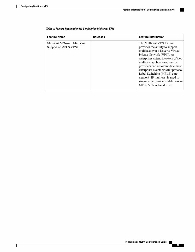
Table 1: Feature Information for Configuring Multicast VPN
Feature InformationReleasesFeature Name
The Multicast VPN featureprovides the ability to supportmulticast over a Layer 3 VirtualPrivate Network (VPN). Asenterprises extend the reach of theirmulticast applications, serviceproviders can accommodate theseenterprises over theirMultiprotocolLabel Switching (MPLS) corenetwork. IP multicast is used tostream video, voice, and data to anMPLS VPN network core.
Multicast VPN—IP MulticastSupport of MPLS VPNs
IP Multicast: MVPN Configuration Guide 21
Configuring Multicast VPNFeature Information for Configuring Multicast VPN

IP Multicast: MVPN Configuration Guide22
Configuring Multicast VPNFeature Information for Configuring Multicast VPN

C H A P T E R 3Configuring Multicast VPN Extranet Support
TheMulticast VPN Extranet Support feature (sometimes referred to as the MVPN Extranet Support feature)enables service providers to distribute IP multicast content originated from one enterprise site to otherenterprise sites. This feature enables service providers to offer the next generation of flexible extranet services,helping to enable business partnerships between different enterprise VPN customers.
This module describes the concepts and the tasks related to configuring Multicast VPN Extranet Support.
• Finding Feature Information, page 23
• Prerequisites for Configuring Multicast VPN Extranet Support, page 23
• Restrictions for Configuring Multicast VPN Extranet Support, page 24
• Information About Multicast VPN Extranet Support, page 24
• How to Configure Multicast VPN Extranet Support, page 31
• Configuration Examples for Multicast VPN Extranet Support, page 39
• Additional References, page 54
• Feature Information for Configuring Multicast VPN Extranet Support, page 56
Finding Feature InformationYour software release may not support all the features documented in this module. For the latest caveats andfeature information, see Bug Search Tool and the release notes for your platform and software release. Tofind information about the features documented in this module, and to see a list of the releases in which eachfeature is supported, see the feature information table.
Use Cisco Feature Navigator to find information about platform support and Cisco software image support.To access Cisco Feature Navigator, go to www.cisco.com/go/cfn. An account on Cisco.com is not required.
Prerequisites for Configuring Multicast VPN Extranet Support• You are familiar with IP multicast concepts and configuration tasks.
• You are familiar with Multicast VPN (MVPN) concepts and configuration tasks.
IP Multicast: MVPN Configuration Guide 23

• You are familiar with Multiprotocol Label Switching (MPLS) Layer 3 Virtual Private Network (VPN)concepts and configuration tasks.
Restrictions for Configuring Multicast VPN Extranet Support• TheMulticast VPN Extranet Support feature supports only Protocol IndependentMulticast (PIM) sparsemode (PIM-SM) and Source Specific Multicast (SSM) traffic; PIM dense mode (PIM-DM) andbidirectional PIM (bidir-PIM) traffic are not supported.
•When configuring extranet MVPNs in a PIM-SM environment, the source and the rendezvous point(RP) must reside in the same site of the MVPN behind the same provider edge (PE) router.
• It is required to configure either all the Receiver MVRF(s) in Source PE or Source MVRF in all theReceiver PE(s) to deliver the Extranet content.
• IPV6 based MVPN Extranet is not supported.
• Only Routed interfaces and Routed interfaces on Port channels are supported towards the core. BDItowards core is not supported.
• The scale data for MVPN extranet is as follows:
◦Maximum number of mVRFs supported is 20
◦Maximum number of mroutes supported (Intranet + extranet) is 1000 in case of default templateand 2000 in case of Video template.
• PIM-SM and PIM-SSM are supported.
• PIM-DM and bidir-PIM are not supported.
• RP must be configured behind the PE router and the source is in the same intranet-MVPN and behindthe CE router.
• Static mroute with fallback-lookup option is supported for RPF lookup².
• Configuring the Receiver mVRF on the Source PE only to implement MVPN Extranet support is notsupported.
Information About Multicast VPN Extranet Support
Overview of MVPN Extranet SupportAn extranet can be viewed as part of a company’s intranet that is extended to users outside the company. Ithas also been described as a “state of mind” in which a VPN is used as a way to do business with othercompanies as well as to sell products and content to customers and companies. An extranet is a VPN connectingthe corporate site or sites to external business partners or suppliers to securely share part of a business’sinformation or operations among them.
MPLS VPNs inherently provide security, ensuring that users access only appropriate information. MPLSVPN extranet services offer extranet users unicast connectivity without compromising the integrity of their
IP Multicast: MVPN Configuration Guide24
Configuring Multicast VPN Extranet SupportRestrictions for Configuring Multicast VPN Extranet Support

corporate data. TheMulticast VPN Extranet Support feature extends this offer to include multicast connectivityto the extranet community of interest.
The Multicast VPN Extranet Support feature enables service providers to distribute IP multicast contentoriginated from one enterprise site to other enterprise sites. This feature enables service providers to offer thenext generation of flexible extranet services, helping to enable business partnerships between different enterpriseVPN customers. Using this feature, service providers can offer multicast extranet contracts to meet variousbusiness partnership requirements, including short-term, annual, and rolling contracts.
Benefits of MVPN Extranet SupportThe Multicast VPN Extranet Support feature can be used to solve such business problems as:
• Efficient content distribution between enterprises
• Efficient content distribution from service providers or content providers to their different enterpriseVPN customers
Components of an Extranet MVPNThe figure below illustrates the components that constitute an extranet MVPN.
•MVRF --Multicast VPN routing and forwarding (VRF) instance. AnMVRF is a multicast-enabled VRF.A VRF consists of an IP routing table, a derived forwarding table, a set of interfaces that use theforwarding table, and a set of rules and routing protocols that determine what goes into the forwardingtable. In general, a VRF includes the routing information that defines a customer VPN site that is attachedto a provider edge (PE) router.
• Source MVRF --An MVRF that can reach the source through a directly connected customer edge (CE)router.
• Receiver MVRF --An MVRF to which receivers are connected through one or more CE devices.
• Source PE --A PE router that has a multicast source behind a directly connected CE router.
IP Multicast: MVPN Configuration Guide 25
Configuring Multicast VPN Extranet SupportOverview of MVPN Extranet Support

• Receiver PE --A PE router that has one or more interested receivers behind a directly connected CErouter.
Figure 3: Components of an Extranet MVPN
Solution for MVPN Extranet SupportFor unicast, there is no difference between an intranet or extranet from a routing perspective; that is, when aVRF imports a prefix, that prefix is reachable through a label-switched path (LSP). If the enterprise owns theprefix, the prefix is considered a part of the corporate intranet; otherwise, the prefix is considered a part of anextranet. For multicast, however, the reachability of a prefix (especially through an LSP) is not sufficient tobuild a multicast distribution tree (MDT).
In order to provide support for extranet MVPN services, the same default MDT group must be configured inthe source and receiver MVRF. Prior to the introduction of the Multicast VPN Extranet Support feature, therewere challenges that prevented service providers from providing extranet MVPN services:
• The source MVRF may not have been configured with a default MDT group, or it may have beenconfigured with a different MDT group as compared to the receiver MVRF. In the former case therewas no way for the source MVRF to forward multicast streams to extranet sites, and in the latter case,there was no way for the separate MVRFs to be linked.
• It was not possible to maintain a forwarding table in cases where the RPF interface and outgoing interfacesbelong to different VRFs.
The Multicast VPN Extranet Support feature solves these challenges as follows:
• The receiver and source MVRF multicast route (mroute) entries are linked.
• The Reverse Path Forwarding (RPF) check relies on unicast routing information to determine the interfacethrough which the source is reachable. This interface is used as the RPF interface.
IP Multicast: MVPN Configuration Guide26
Configuring Multicast VPN Extranet SupportOverview of MVPN Extranet Support

Configuration Guidelines for MVPN Extranet SupportTwo configuration options are available to provide extranet MVPN services:
• Option 1--Configure the source MVRF on the receiver PE router.
• Option 2--Configure the receiver MVRF on the source PE router.
MVPN Extranet Support Configuration Guidelines for Option 1To provide extranet MVPN services to enterprise VPN customers by configuring the receiver MVRF on thesource PE router (Option 1), you would complete the following procedure:
• For each extranet site, you would configure an additional MVRF on the source PE router, that has thesame default MDT group as the receiver MVRF, if the MVRF is not configured on the source PE.
• In the receiver MVRF configuration, you would configure the same unicast routing policy on the sourceand receiver PE routers to import routes from the source MVRF to the receiver MVRF.
The figure illustrates the flow of multicast traffic in an extranet MVPN topology where a receiver MVRF isconfigured on the source PE router (Option 1). In the topology, an MVRF is configured for VPN-Green andVPN-Red on PE1, the source PE router. A multicast source behind PE1 is sending out a multicast stream tothe MVRF for VPN-Green, and there are interested receivers behind PE2 and PE3, the receiver PE routersfor VPN-Red and VPN-Green, respectively. After PE1 receives the packets from the source in the MVRF forVPN-Green, it independently replicates and encapsulates the packets in the MVRF for VPN-Green andVPN-Red and forwards the packets. After receiving the packets from this source, PE2 and PE3 decapsulateand forward the packets to the respective MVRFs.
Figure 4: Packet Flow for MVPN Extranet Support Configuration Option 1
IP Multicast: MVPN Configuration Guide 27
Configuring Multicast VPN Extranet SupportConfiguration Guidelines for MVPN Extranet Support

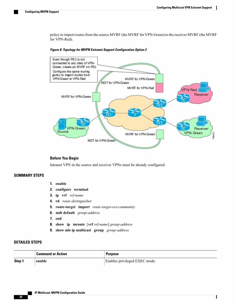
MVPN Extranet Support Configuration Guidelines for Option 2To provide extranetMVPN services to enterprise VPN customers by configuring a sourceMVRF on a receiverPE router (Option 2), you would complete the following procedure:
• On a receiver PE router that has one or more interested receivers in a extranet site behind a directlyconnected CE router, configure an additional MVRF that has the same default MDT group as the siteconnected to the multicast source, if the MVRF is not configured.
• On the receiver PE router, you would configure the same unicast routing policy to import routes fromthe source MVRF to the receiver MVRF.
The figure illustrates the flow of multicast traffic in an extranet MVPN topology where the source MVRF isconfigured on a receiver PE router (Option 2). In the topology, an MVRF is configured for VPN-Green andVPN-Red on PE2, a receiver PE router. A multicast source behind PE1, the source PE router, is sending outa multicast stream to the MVRF for VPN-Green, and there are interested receivers behind PE2, the receiverPE router for VPN-Red, and behind PE3, the receiver PE router for VPN-Green. After PE1 receives the packetsfrom the source in the MVRF for VPN-Green, it replicates and forwards the packets to PE2 and PE3, becauseboth routers are connected to receivers in VPN-Green. The packets that originated from VPN-Green are thenreplicated on PE2 and forwarded to the interested receivers in VPN-Red and are replicated on PE3 andforwarded to the interested receivers in VPN-Green.
Figure 5: Packet Flow for MVPN Extranet Support Configuration Option 2
RPF for MVPN Extranet Support Using Imported RoutesYou must configure either the receiver MVRF on the source PE router (Option 1) or the source MVRF onthe receiver PE router (Option 2) for extranet links to be created. Once configured, RPF relies on unicastrouting information to determine the interface through which the source is reachable. This interface is usedas the RPF interface. No additional configuration is required for RPF resolution. The Multicast VPN Extranet
IP Multicast: MVPN Configuration Guide28
Configuring Multicast VPN Extranet SupportConfiguration Guidelines for MVPN Extranet Support

Support feature supports RPF from one VRF to another VRF, from a VRF to the global routing table, andfrom the global routing table to a VRF.
RPF for MVPN Extranet Support Using Static Mroutes
This capability is not supported for MVPNv6 extranet.Note
By default, an extranet MVPN relies on unicast routing policies to determine the RPF interface. When theRPF lookup originates in a receiver MVRF, and it finds that the RPF interface does not lie in the sameMVRF,the router uses the information in the Border Gateway Protocol (BGP) imported route to determine the sourceMVRF. The RPF lookup then continues and resolves in the source MVRF. In cases where the multicast andunicast topologies are incongruent, you can override the default behavior by configuring a static mroute inthe receiver MVRF to explicitly specify the source MVRF using the ip mroute command with thefallback-lookup keyword and vrf vrf-name keyword and argument.
Static mroutes can also be configured to support RPF for extranet MVPN in the case where the source ispresent in an MVRF and the receiver is in the global table. In this case, because BGP does not allow VPNv4routes to be imported into the IPv4 routing table, unicast cannot obtain the source MVRF information neededto resolve the RPF lookup. To enable the RPF lookup to be resolved in this case, a static mroute can beconfigured to explicitly specify the source MVRF using the ip mroute command with the fallback-lookupkeyword and the global keyword.
Multicast VPN Extranet VRF SelectThe Multicast VPN VRF Select feature is configured by creating group-based VRF selection policies.Group-based VRF selection policies are configured using the ip multicast rpf select command. The ipmulticast rpf selectcommand is used to configure RPF lookups originating in a receiver MVRF or in theglobal routing table to be resolved in a source MVRF or in the global routing table based on group address.Access Control Lists (ACLs) are used to define the groups to be applied to group-based VRF selection policies.
The figure illustrates an extranet MVPN topology with the Multicast VPN VRF Select feature configured. Inthis topology, (S, G1) and (S, G2) PIM joins originating from VPN-Green, the receiver VRF, are forwarded
IP Multicast: MVPN Configuration Guide 29
Configuring Multicast VPN Extranet SupportMulticast VPN Extranet VRF Select

to PE1, the receiver PE. Based on the group-based VRF selection policies configured, PE1 sends the PIMjoins to VPN-Red and VPN-Blue for groups G1 and G2, respectively.
Figure 6: RPF Lookups Using Group-Based VRF Selection Policies
MVPNv6 ExtranetIPv6 Multicast Virtual Private Network (MVPNv6) provides multiple VPN support that enables serviceproviders to provide multicast-enabled private IPv6 networks to their customers using the existing IPv4 backbone. In the MVPNv6 implementation, the IPv6 multicast traffic is carried over the same IPv4-based corenetwork and both the IPv4 and IPv6 VPN traffic are carried over the same tunnels simultaneously. MVPNv6extranet forwards IPv6 multicast traffic across VRF boundaries on a PE device to connect the service providerto external business partners or suppliers for securely sharing information or operations among them.
Hardware Acceleration for Multicast VPN Extranet Support on Catalyst 6500Series Switches
Beginning in Cisco IOS Release 12.2(33)SXH, when theMulticast VPNExtranet Support feature is configuredon Catalyst 6500 series switches, forwarding entries for source and receiver MVRFs are linked in hardware(similar to how they are linked in software for this feature) and packets are replicated in hardware when beingforwarded to extranet MVPN sites. This functionality is referred to as the Hardware Acceleration for MulticastVPN Extranet Support feature.
IP Multicast: MVPN Configuration Guide30
Configuring Multicast VPN Extranet SupportMVPNv6 Extranet

How to Configure Multicast VPN Extranet Support
Configuring MVPN SupportPerform one of the following tasks to provide extranet MVPN capabilities in an IPv4 core network:
Configuring the Receiver MVRF on the Source PE - Option 1Perform this task to configure the receiver MVRF on the source PE router (Option 1) and provide support forextranet MVPN services.
In the following figure, the source PE router is PE1. To provide extranet MVPN services from one enterpriseVPN site (VPN-Green) to another enterprise VPN site (VPN-Red) using Option 1, configure the receiverMVRF on the source PE router. In the receiver MVRF configuration, the default MDT group must be thesame on both the source and receiver PE routers. In addition, you must configure the same unicast routingpolicy to import routes from the sourceMVRF (heMVRF for VPN-Green) to the receiver MVRF (theMVRFfor VPN-Red).
Figure 7: Topology for MVPN Extranet Support Configuration Option 1
Before You Begin
Intranet VPN in the source and receiver VPNs must be already configured.
IP Multicast: MVPN Configuration Guide 31
Configuring Multicast VPN Extranet SupportHow to Configure Multicast VPN Extranet Support

SUMMARY STEPS
1. enable2. configure terminal3. ip vrf vrf-name4. rd route-distinguisher5. route-target import route-target-ext-community6. mdt default group-address7. end8. show ip mroute [vrf vrf-name] group-address
DETAILED STEPS
PurposeCommand or Action
Enables privileged EXEC mode.enableStep 1
Example:
Router> enable
• Enter your password if prompted.
Enters global configuration mode.configure terminal
Example:
Router# configure terminal
Step 2
Defines the VPN routing instance by assigning a VRF name and entersVRF configuration mode.
ip vrf vrf-name
Example:
Router(config)# ip vrf VPN-Red
Step 3
• The vrf-name argument is the name assigned to a VRF.
Creates routing and forwarding tables.rd route-distinguisherStep 4
Example:
Router(config-vrf)# rd 55:2222
• Specify the route-distinguisher argument to add an 8-byte value to anIPv4 prefix to create a VPN IPv4 prefix. You can enter an RD in eitherof these formats:
• 16-bit autonomous system number: your 32-bit number, forexample, 101:3
• 32-bit IP address: your 16-bit number, for example,192.168.122.15:1
Creates a route-target extended community for a VRF.route-target importroute-target-ext-community
Step 5
• The import keyword imports routing information from the targetVPN extended community.
IP Multicast: MVPN Configuration Guide32
Configuring Multicast VPN Extranet SupportConfiguring MVPN Support

PurposeCommand or Action
Example:
Router(config-vrf)# route-targetimport 55:1111
• The route-target-ext-community argument adds the route-targetextended community attributes to the VRF’s list of import, export, orboth (import and export) route-target extended communities.
For content to be distributed from the sourceMVRF to the receiverMVRF, you must configure the same unicast routing policy on thesource and receiver PE routers to import routes from the sourceVRF to the receiver VRF.
Note
Configures the multicast group address range for data MDT groups for aVRF.
mdt default group-address
Example:
Router(config-vrf)# mdt default232.3.3.3
Step 6
• A tunnel interface is created as a result of this command.
• By default, the destination address of the tunnel header is thegroup-address argument.
Exits VRF configuration mode and returns to privileged EXEC mode.end
Example:
Router(config-vrf)# end
Step 7
(Optional) Displays the contents of the IP multicast mroute table for aspecific group address.
show ip mroute [vrf vrf-name]group-address
Example:
Router# show ip mroute 232.3.3.3
Step 8
Configuring the Source MVRF on the Receiver PE - Option 2Perform this task to configure the source MVRF on the receiver PE router (Option 2) and provide support forextranet MVPN services.
In the following figure, the receiver PE router is PE2. To provide support for extranet MVPN services fromone enterprise VPN site (VPN-Green) to another enterprise VPN site (VPN-Red) using Option 2, configurethe source MVRF on the receiver PE router. The MDT group configuration of the source MVRF must be thesame on both the source and receiver PE routers. In addition, you must configure the same unicast routing
IP Multicast: MVPN Configuration Guide 33
Configuring Multicast VPN Extranet SupportConfiguring MVPN Support
policy to import routes from the sourceMVRF (theMVRF for VPN-Green) to the receiverMVRF (theMVRFfor VPN-Red).
Figure 8: Topology for MVPN Extranet Support Configuration Option 2
Before You Begin
Intranet VPN in the source and receiver VPNs must be already configured.
SUMMARY STEPS
1. enable2. configure terminal3. ip vrf vrf-name4. rd route-distinguisher5. route-target import route-target-ext-community6. mdt default group-address7. end8. show ip mroute [vrf vrf-name] group-address9. show mls ip multicast group group-address
DETAILED STEPS
PurposeCommand or Action
Enables privileged EXEC mode.enableStep 1
IP Multicast: MVPN Configuration Guide34
Configuring Multicast VPN Extranet SupportConfiguring MVPN Support

PurposeCommand or Action
Example:
Router> enable
• Enter your password if prompted.
Enters global configuration mode.configure terminal
Example:
Router# configure terminal
Step 2
Defines the VPN routing instance by assigning a VRF name and entersVRF configuration mode.
ip vrf vrf-name
Example:
Router(config)# ip vrf VPN-Red
Step 3
• The vrf-name argument is the name assigned to a VRF.
Creates routing and forwarding tables.rd route-distinguisherStep 4
Example:
Router(config-vrf)# rd 55:1111
• The route-distinguisher argument adds an 8-byte value to an IPv4prefix to create a VPN IPv4 prefix. You can enter an RD in eitherof these formats:
• 16-bit autonomous system number: your 32-bit number, forexample, 101:3
• 32-bit IP address: your 16-bit number, for example,192.168.122.15:1
Creates a route-target extended community for a VRF.route-target importroute-target-ext-community
Step 5
• The import keyword exports routing information to the target VPNextended community.
Example:
Router(config-vrf)# route-targetimport 55:1111
• The route-target-ext-community argument adds the route-targetextended community attributes to the VRF’s list of import, export,or both (import and export) route-target extended communities.
For content to be distributed from the source MVRF to thereceiver MVRF, you must configure the same unicast routingpolicy on the source and receiver PE routers to import routesfrom the source VRF to the receiver VRF.
Note
Configures the multicast group address range for data MDT groups for aVRF.
mdt default group-address
Example:
Router(config-vrf)# mdt default232.1.1.1
Step 6
• A tunnel interface is created as a result of this command.
• By default, the destination address of the tunnel header is thegroup-address argument.
IP Multicast: MVPN Configuration Guide 35
Configuring Multicast VPN Extranet SupportConfiguring MVPN Support

PurposeCommand or Action
Exits VRF configuration mode and returns to privileged EXEC mode.end
Example:
Router(config-vrf)# end
Step 7
(Optional) Displays the contents of the IP multicast mroute table for aspecific group address.
show ip mroute [vrf vrf-name]group-address
Step 8
Example:
Router# show ip mroute 232.1.1.1
(Optional) DisplaysMLS information related to a specific multicast group.show mls ip multicast groupgroup-address
Step 9
Example:
Router# show mls ip multicast group232.3.3.3
Configuring RPF for MVPN Extranet Support Using Static Mroutes
This task is not supported for MVPNv6 extranet.Note
Before You Begin
You must configure support for extranet MVPN services prior to performing this task.
SUMMARY STEPS
1. enable2. configure terminal3. ip mroute vrf vrf-name source-address mask fallback-lookup {global | vrf vrf-name} [distance]4. end5. show ip mroute [vrf vrf-name] group-address
DETAILED STEPS
PurposeCommand or Action
Enables privileged EXEC mode.enableStep 1
IP Multicast: MVPN Configuration Guide36
Configuring Multicast VPN Extranet SupportConfiguring RPF for MVPN Extranet Support Using Static Mroutes
PurposeCommand or Action
Example:
Router> enable
• Enter your password if prompted.
Enters global configuration mode.configure terminal
Example:
Router# configure terminal
Step 2
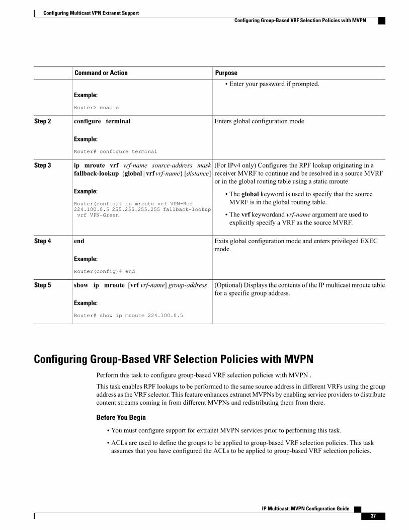
(For IPv4 only) Configures the RPF lookup originating in areceiver MVRF to continue and be resolved in a source MVRFor in the global routing table using a static mroute.
ip mroute vrf vrf-name source-address maskfallback-lookup {global | vrf vrf-name} [distance]
Example:
Router(config)# ip mroute vrf VPN-Red
Step 3
• The global keyword is used to specify that the sourceMVRF is in the global routing table.
224.100.0.5 255.255.255.255 fallback-lookupvrf VPN-Green • The vrf keywordand vrf-name argument are used to
explicitly specify a VRF as the source MVRF.
Exits global configuration mode and enters privileged EXECmode.
end
Example:
Router(config)# end
Step 4
(Optional) Displays the contents of the IP multicast mroute tablefor a specific group address.
show ip mroute [vrf vrf-name] group-address
Example:
Router# show ip mroute 224.100.0.5
Step 5
Configuring Group-Based VRF Selection Policies with MVPNPerform this task to configure group-based VRF selection policies with MVPN .
This task enables RPF lookups to be performed to the same source address in different VRFs using the groupaddress as the VRF selector. This feature enhances extranet MVPNs by enabling service providers to distributecontent streams coming in from different MVPNs and redistributing them from there.
Before You Begin
• You must configure support for extranet MVPN services prior to performing this task.
• ACLs are used to define the groups to be applied to group-based VRF selection policies. This taskassumes that you have configured the ACLs to be applied to group-based VRF selection policies.
IP Multicast: MVPN Configuration Guide 37
Configuring Multicast VPN Extranet SupportConfiguring Group-Based VRF Selection Policies with MVPN

SUMMARY STEPS
1. enable2. configure terminal3. Use the following commands:
• ip multicast [vrf receiver-vrf-name] rpf select {global | vrf source-vrf-name} group-list access-list
4. Repeat step 3 to create additional group-based VRF selection policies.5. end6. Use the following commands:
• show ip} rpf [vrf vrf-name] select
7. Use one of the following commands:
• show ip rpf [vrf vrf-name] source-address [group-address]
DETAILED STEPS
PurposeCommand or Action
Enables privileged EXEC mode.enableStep 1
Example:
Router> enable
• Enter your password if prompted.
Enters global configuration mode.configure terminal
Example:
Router# configure terminal
Step 2
Use the following commands:Step 3 • (For IPv4 only) Configures RPF lookups originatingin a receiver MVRF or in the global routing table to
• ip multicast [vrf receiver-vrf-name] rpf select{global | vrf source-vrf-name} group-listaccess-list
be resolved in a sourceMVRF or in the global routingtable based on group address.
Example:Router(config)# ip multicast vrf VPN-Green rpfselect vrf VPN-Red group-list 1
--Repeat step 3 to create additional group-based VRFselection policies.
Step 4
IP Multicast: MVPN Configuration Guide38
Configuring Multicast VPN Extranet SupportConfiguring Group-Based VRF Selection Policies with MVPN

PurposeCommand or Action
Exits global configurationmode and enters privileged EXECmode.
end
Example:
Router(config)# end
Step 5
Displays group-to-VRF mapping information.Use the following commands:Step 6
• show ip} rpf [vrf vrf-name] select
Example:Router# show ip rpf select
Displays information about how IP multicast routing doesRPF.
Use one of the following commands:Step 7
• show ip rpf [vrf vrf-name] source-address[group-address] • Use this command after configuring group-based VRF
selection policies to confirm that RPF lookups arebeing performed based on the group address, and to
Example:
Router# show ip rpf 172.16.10.13
display the VRF where the RPF lookup is beingperformed.
Configuration Examples for Multicast VPN Extranet Support
Example Configuring the Receiver VRF on the Source PE Router - Option 1The following example shows the configurations for PE1, the source PE router, and PE2, the receiver PErouter, in the figure. In this example, extranetMVPN services are supported betweenVPN-Green andVPN-Red
IP Multicast: MVPN Configuration Guide 39
Configuring Multicast VPN Extranet SupportConfiguration Examples for Multicast VPN Extranet Support

by configuring the receiver MVRF for VPN-Red on PE1, the source PE router. The MVRF configuration forVPN-Red is configured to import routes from the MVRF for VPN-Green to the MVRF for VPN-Red.
Figure 9: Topology for MVPN Extranet Support Option 1 Configuration Example
PE1 Configuration
ip cef!ip vrf VPN-Greenrd 55:1111route-target export 55:1111route-target import 55:1111mdt default 232.1.1.1!ip vrf VPN-Redrd 55:2222route-target export 55:2222route-target import 55:2222route-target import 55:1111mdt default 232.3.3.3!ip multicast-routingip multicast-routing vrf VPN-Greenip multicast-routing vrf VPN-Red!interface Loopback0ip address 10.1.0.1 255.255.255.0ip pim sparse-dense-mode!...!router bgp 55no synchronizationbgp log-neighbor-changesneighbor 10.2.0.2 remote-as 55neighbor 10.2.0.2 update-source Loopback0
IP Multicast: MVPN Configuration Guide40
Configuring Multicast VPN Extranet SupportExample Configuring the Receiver VRF on the Source PE Router - Option 1

!address-family ipv4 mdtneighbor 10.2.0.2 activateneighbor 10.2.0.2 send-community extended!address-family vpnv4neighbor 10.2.0.2 activateneighbor 10.2.0.2 send-community extended!
PE2 Configuration
!ip vrf VPN-Redrd 55:2222route-target export 55:2222route-target import 55:2222route-target import 55:1111mdt default 232.3.3.3!ip multicast-routingip multicast-routing vrf VPN-Red!interface Loopback0ip address 10.2.0.2 255.255.255.0ip pim sparse-dense-mode!...!router bgp 55no synchronizationbgp log-neighbor-changesneighbor 10.1.0.1 remote-as 55neighbor 10.1.0.1 update-source Loopback0!address-family ipv4 mdtneighbor 10.1.0.1 activateneighbor 10.1.0.1 send-community extended!address-family vpnv4neighbor 10.1.0.1 activateneighbor 10.1.0.1 send-community extended!
States in the Global Table on PE1 and PE2 for the MDT Default Group 232.3.3.3
The following are sample outputs from the show ip mroute command on PE1 and PE2. The sample outputsshow the global table for the MDT default group 232.3.3.3 on PE1 and PE2.
PE1# show ip mroute 232.3.3.3IP Multicast Routing TableFlags: D - Dense, S - Sparse, B - Bidir Group, s - SSM Group, C - Connected,
L - Local, P - Pruned, R - RP-bit set, F - Register flag,T - SPT-bit set, J - Join SPT, M - MSDP created entry,X - Proxy Join Timer Running, A - Candidate for MSDP Advertisement,U - URD, I - Received Source Specific Host Report,Z - Multicast Tunnel, z - MDT-data group sender,Y - Joined MDT-data group, y - Sending to MDT-data groupV - RD & Vector, v - Vector
Outgoing interface flags: H - Hardware switched, A - Assert winnerTimers: Uptime/ExpiresInterface state: Interface, Next-Hop or VCD, State/Mode(10.1.0.1, 232.3.3.3), 00:46:27/00:03:27, flags: sTIncoming interface: Loopback0, RPF nbr 0.0.0.0Outgoing interface list:Ethernet0/0, Forward/Sparse-Dense, 00:45:17/00:02:44
IP Multicast: MVPN Configuration Guide 41
Configuring Multicast VPN Extranet SupportExample Configuring the Receiver VRF on the Source PE Router - Option 1

(10.2.0.2, 232.3.3.3), 00:45:17/00:02:57, flags: sTIZIncoming interface: Ethernet0/0, RPF nbr 224.0.1.4Outgoing interface list:MVRF VPN-Red, Forward/Sparse-Dense, 00:45:17/00:01:09
PE2# show ip mroute 232.3.3.3IP Multicast Routing TableFlags: D - Dense, S - Sparse, B - Bidir Group, s - SSM Group, C - Connected,
L - Local, P - Pruned, R - RP-bit set, F - Register flag,T - SPT-bit set, J - Join SPT, M - MSDP created entry,X - Proxy Join Timer Running, A - Candidate for MSDP Advertisement,U - URD, I - Received Source Specific Host Report,Z - Multicast Tunnel, z - MDT-data group sender,Y - Joined MDT-data group, y - Sending to MDT-data groupV - RD & Vector, v - Vector
Outgoing interface flags: H - Hardware switched, A - Assert winnerTimers: Uptime/ExpiresInterface state: Interface, Next-Hop or VCD, State/Mode(10.1.0.1, 232.3.3.3), 00:45:08/00:02:37, flags: sTIZIncoming interface: Ethernet1/0, RPF nbr 224.0.2.4Outgoing interface list:MVRF VPN-Red, Forward/Sparse-Dense, 00:45:08/00:01:27
(10.2.0.2, 232.3.3.3), 00:46:19/00:03:07, flags: sTIncoming interface: Loopback0, RPF nbr 0.0.0.0Outgoing interface list:Ethernet1/0, Forward/Sparse-Dense, 00:45:08/00:02:49
States in the Global Table on PE1 and PE2 for the MDT Default Group 232.3.3.3 When PE1 and PE2 Are Catalyst6500 Series Switches Configured for MVPN Extranet Support
The following are sample outputs from the show ip mroute on PE1 and PE2, when PE1 and PE2 are Catalyst6500 series switches that have been configured to support extranet MVPN services. The sample output fromthe show ip mroute command shows the global table for the MDT default group 232.3.3.3 on PE1 and PE2.In the output, the “RPF-MFD” flag indicates that a multicast flow is completely hardware switched and “H”flag indicates that the flow is being hardware switched on an outgoing interface.
PE1# show ip mroute 232.3.3.3IP Multicast Routing TableFlags: D - Dense, S - Sparse, B - Bidir Group, s - SSM Group, C - Connected,
L - Local, P - Pruned, R - RP-bit set, F - Register flag,T - SPT-bit set, J - Join SPT, M - MSDP created entry,X - Proxy Join Timer Running, A - Candidate for MSDP Advertisement,U - URD, I - Received Source Specific Host Report,Z - Multicast Tunnel, z - MDT-data group sender,Y - Joined MDT-data group, y - Sending to MDT-data groupV - RD & Vector, v - Vector
Outgoing interface flags: H - Hardware switched, A - Assert winnerTimers: Uptime/ExpiresInterface state: Interface, Next-Hop or VCD, State/Mode(10.1.0.1, 232.3.3.3), 00:46:27/00:03:27, flags: sTIncoming interface: Loopback0, RPF nbr 0.0.0.0, RPF-MFDOutgoing interface list:GigabitEthernet2/16, Forward/Sparse-Dense, 00:45:17/00:02:44, H
(10.2.0.2, 232.3.3.3), 00:45:17/00:02:57, flags: sTIZIncoming interface: GigabitEthernet2/16, RPF nbr 224.0.1.4, RPF-MFDOutgoing interface list:MVRF VPN-Red, Forward/Sparse-Dense, 00:45:17/00:01:09, H
PE2# show ip mroute 232.3.3.3IP Multicast Routing TableFlags: D - Dense, S - Sparse, B - Bidir Group, s - SSM Group, C - Connected,
L - Local, P - Pruned, R - RP-bit set, F - Register flag,T - SPT-bit set, J - Join SPT, M - MSDP created entry,X - Proxy Join Timer Running, A - Candidate for MSDP Advertisement,U - URD, I - Received Source Specific Host Report,Z - Multicast Tunnel, z - MDT-data group sender,Y - Joined MDT-data group, y - Sending to MDT-data groupV - RD & Vector, v - Vector
Outgoing interface flags: H - Hardware switched, A - Assert winner
IP Multicast: MVPN Configuration Guide42
Configuring Multicast VPN Extranet SupportExample Configuring the Receiver VRF on the Source PE Router - Option 1

Timers: Uptime/ExpiresInterface state: Interface, Next-Hop or VCD, State/Mode(10.1.0.1, 232.3.3.3), 00:45:08/00:02:37, flags: sTIZIncoming interface: GigabitEthernet4/1, RPF nbr 224.0.2.4, RPF-MFDOutgoing interface list:MVRF VPN-Red, Forward/Sparse-Dense, 00:45:08/00:01:27, H
(10.2.0.2, 232.3.3.3), 00:46:19/00:03:07, flags: sTIncoming interface: Loopback0, RPF nbr 0.0.0.0, RPF-MFDOutgoing interface list:GigabitEthernet4/1, Forward/Sparse-Dense, 00:45:08/00:02:49, H
States in the VRF Table for VPN-Green on PE1 After Receivers in VPN-Red Join Multicast Group 228.8.8.8
The following is sample output from the show ip mroute command on PE1. The sample output shows thestate of the VRF table for VPN-Green on PE1 when receivers join the multicast group 228.8.8.8. The outputindicates that extranet receivers in VPN-Red are receiving content from a source in VPN-Green that is sendingto multicast group 228.8.8.8. The “E” flag in the output indicates that a (*, G) or (S, G) entry in the VRFrouting table is a source VRF entry and has extranet receiver MVRF mroute entries linked to it.
PE1# show ip mroute vrf VPN-Green 228.8.8.8IP Multicast Routing TableFlags: D - Dense, S - Sparse, B - Bidir Group, s - SSM Group, C - Connected,
L - Local, P - Pruned, R - RP-bit set, F - Register flag,T - SPT-bit set, J - Join SPT, M - MSDP created entry, E - Extranet,X - Proxy Join Timer Running, A - Candidate for MSDP Advertisement,U - URD, I - Received Source Specific Host Report,Z - Multicast Tunnel, z - MDT-data group sender,Y - Joined MDT-data group, y - Sending to MDT-data group,V - RD & Vector, v - Vector
Outgoing interface flags: H - Hardware switched, A - Assert winnerTimers: Uptime/ExpiresInterface state: Interface, Next-Hop or VCD, State/Mode(*, 228.8.8.8), 00:01:38/stopped, RP 10.100.0.5, flags: SEIncoming interface: Ethernet3/0, RPF nbr 10.1.1.5Outgoing interface list: NullExtranet receivers in vrf VPN-Red:
(*, 228.8.8.8), 00:01:38/stopped, RP 10.100.0.5, OIF count: 1, flags: S(10.1.1.200, 228.8.8.8), 00:00:05/00:02:54, flags: TEIncoming interface: Ethernet3/0, RPF nbr 10.1.1.5Outgoing interface list: NullExtranet receivers in vrf VPN-Red:(10.1.1.200, 228.8.8.8), 00:00:05/stopped, OIF count: 1, flags:
States in the VRF Table for VPN-Green on PE1 After Receivers in VPN-Red Join Multicast Group 228.8.8.8When PE1 Is a Catalyst 6500 Series Switch Configured for MVPN Extranet Support
The following are sample outputs from the show ipmroute on PE1, when PE1 is a Catalyst 6500 series switchconfigured to support extranet MVPN services. The sample output from the show ipmroute command showsthe state of the VRF table for VPN-Green on PE1 when receivers join the multicast group 228.8.8.8. Thesample output indicate that extranet receivers in VPN-Red are receiving content from a source in VPN-Greenthat is sending to multicast group 228.8.8.8.
PE1# show ip mroute vrf VPN-Green 228.8.8.8IP Multicast Routing TableFlags: D - Dense, S - Sparse, B - Bidir Group, s - SSM Group, C - Connected,
L - Local, P - Pruned, R - RP-bit set, F - Register flag,T - SPT-bit set, J - Join SPT, M - MSDP created entry, E - Extranet,X - Proxy Join Timer Running, A - Candidate for MSDP Advertisement,U - URD, I - Received Source Specific Host Report,Z - Multicast Tunnel, z - MDT-data group sender,Y - Joined MDT-data group, y - Sending to MDT-data group,V - RD & Vector, v - Vector
Outgoing interface flags: H - Hardware switched, A - Assert winnerTimers: Uptime/ExpiresInterface state: Interface, Next-Hop or VCD, State/Mode
IP Multicast: MVPN Configuration Guide 43
Configuring Multicast VPN Extranet SupportExample Configuring the Receiver VRF on the Source PE Router - Option 1

(*, 228.8.8.8), 00:01:38/stopped, RP 10.100.0.5, flags: SEIncoming interface: GigabitEthernet3/1, RPF nbr 10.1.1.5, RPF-MFDOutgoing interface list: NullExtranet receivers in vrf VPN-Red:
(*, 228.8.8.8), 00:01:38/stopped, RP 10.100.0.5, OIF count: 1, flags: S(10.1.1.200, 228.8.8.8), 00:00:05/00:02:54, flags: TEIncoming interface: GigabitEthernet3/1, RPF nbr 10.1.1.5, RPF-MFDOutgoing interface list: NullExtranet receivers in vrf VPN-Red:(10.1.1.200, 228.8.8.8), 00:00:05/stopped, OIF count: 1, flags:
States in the VRF Table for VPN-Red on PE1 After Receivers in VPN-Red Join Multicast Group 228.8.8.8
The following is sample output from the show ip mroute command on PE1. The sample output shows thestate of the VRF table for VPN-Red on PE1 when receivers join the multicast group 228.8.8.8. The “usingvrf VPN-Green” field indicates that VPN-Red is using unicast routing information from VPN-Green todetermine the RPF interface through which the source is reachable.
PE1# show ip mroute vrf VPN-Red 228.8.8.8IP Multicast Routing TableFlags: D - Dense, S - Sparse, B - Bidir Group, s - SSM Group, C - Connected,
L - Local, P - Pruned, R - RP-bit set, F - Register flag,T - SPT-bit set, J - Join SPT, M - MSDP created entry, E - Extranet,X - Proxy Join Timer Running, A - Candidate for MSDP Advertisement,U - URD, I - Received Source Specific Host Report,Z - Multicast Tunnel, z - MDT-data group sender,Y - Joined MDT-data group, y - Sending to MDT-data group,V - RD & Vector, v - Vector
Outgoing interface flags: H - Hardware switched, A - Assert winnerTimers: Uptime/ExpiresInterface state: Interface, Next-Hop or VCD, State/Mode(*, 228.8.8.8), 00:01:45/stopped, RP 10.100.0.5, flags: SIncoming interface: Ethernet3/0, RPF nbr 10.1.1.5, using vrf VPN-GreenOutgoing interface list:Tunnel2, Forward/Sparse-Dense, 00:01:45/00:02:49
(10.1.1.200, 228.8.8.8), 00:00:12/00:03:27, flags:Incoming interface: Ethernet3/0, RPF nbr 10.1.1.5, using vrf VPN-GreenOutgoing interface list:Tunnel2, Forward/Sparse-Dense, 00:00:12/00:03:18
States in the VRF Table for VPN-Red on PE1 After Receivers in VPN-Red Join Multicast Group 228.8.8.8 WhenPE1 Is a Catalyst 6500 Series Switches Configured for MVPN Extranet Support
PE1# show ip mroute vrf VPN-Red 228.8.8.8IP Multicast Routing TableFlags: D - Dense, S - Sparse, B - Bidir Group, s - SSM Group, C - Connected,
L - Local, P - Pruned, R - RP-bit set, F - Register flag,T - SPT-bit set, J - Join SPT, M - MSDP created entry, E - Extranet,X - Proxy Join Timer Running, A - Candidate for MSDP Advertisement,U - URD, I - Received Source Specific Host Report,Z - Multicast Tunnel, z - MDT-data group sender,Y - Joined MDT-data group, y - Sending to MDT-data group,V - RD & Vector, v - Vector
Outgoing interface flags: H - Hardware switched, A - Assert winnerTimers: Uptime/ExpiresInterface state: Interface, Next-Hop or VCD, State/Mode(*, 228.8.8.8), 00:01:45/stopped, RP 10.100.0.5, flags: SIncoming interface: GigabitEthernet3/1, RPF nbr 10.1.1.5, using vrf VPN-Green, RPF-MFDOutgoing interface list:Tunnel2, Forward/Sparse-Dense, 00:01:45/00:02:49, H
(10.1.1.200, 228.8.8.8), 00:00:12/00:03:27, flags:Incoming interface: GigabitEthernet3/1, RPF nbr 10.1.1.5, using vrf VPN-Green, RPF-MFDOutgoing interface list:Tunnel2, Forward/Sparse-Dense, 00:00:12/00:03:18, H
IP Multicast: MVPN Configuration Guide44
Configuring Multicast VPN Extranet SupportExample Configuring the Receiver VRF on the Source PE Router - Option 1

States in the VRF Table for VPN-Red on PE2 After Receivers in VPN-Red Join Multicast Group 228.8.8.8
The following is sample output from the show ip mroute command on PE2. The sample output shows theVRF table for VPN-Red on PE2 when receivers join the multicast group 228.8.8.8.
PE2# show ip mroute vrf VPN-Red 228.8.8.8IP Multicast Routing TableFlags: D - Dense, S - Sparse, B - Bidir Group, s - SSM Group, C - Connected,
L - Local, P - Pruned, R - RP-bit set, F - Register flag,T - SPT-bit set, J - Join SPT, M - MSDP created entry, E - Extranet,X - Proxy Join Timer Running, A - Candidate for MSDP Advertisement,U - URD, I - Received Source Specific Host Report,Z - Multicast Tunnel, z - MDT-data group sender,Y - Joined MDT-data group, y - Sending to MDT-data group,V - RD & Vector, v - Vector
Outgoing interface flags: H - Hardware switched, A - Assert winnerTimers: Uptime/ExpiresInterface state: Interface, Next-Hop or VCD, State/Mode(*, 228.8.8.8), 00:00:28/stopped, RP 10.100.0.5, flags: SIncoming interface: Tunnel1, RPF nbr 10.1.0.1Outgoing interface list:Ethernet9/0, Forward/Sparse-Dense, 00:00:28/00:03:02
(10.1.1.200, 228.8.8.8), 00:00:00/00:03:29, flags:Incoming interface: Tunnel1, RPF nbr 10.1.0.1Outgoing interface list:Ethernet9/0, Forward/Sparse-Dense, 00:00:00/00:03:29
States in the VRF Table for VPN-Red on PE2 After Receivers in VPN-Red Join Multicast Group 228.8.8.8 WhenPE2 Is a Catalyst 6500 Series Switch Configured for MVPN Extranet Support
PE2# show ip mroute vrf VPN-Red 228.8.8.8IP Multicast Routing TableFlags: D - Dense, S - Sparse, B - Bidir Group, s - SSM Group, C - Connected,
L - Local, P - Pruned, R - RP-bit set, F - Register flag,T - SPT-bit set, J - Join SPT, M - MSDP created entry, E - Extranet,X - Proxy Join Timer Running, A - Candidate for MSDP Advertisement,U - URD, I - Received Source Specific Host Report,Z - Multicast Tunnel, z - MDT-data group sender,Y - Joined MDT-data group, y - Sending to MDT-data group,V - RD & Vector, v - Vector
Outgoing interface flags: H - Hardware switched, A - Assert winnerTimers: Uptime/ExpiresInterface state: Interface, Next-Hop or VCD, State/Mode(*, 228.8.8.8), 00:00:28/stopped, RP 10.100.0.5, flags: SIncoming interface: Tunnel1, RPF nbr 10.1.0.1, RPF-MFDOutgoing interface list:GigabitEthernet9/1, Forward/Sparse-Dense, 00:00:28/00:03:02, H
(10.1.1.200, 228.8.8.8), 00:00:00/00:03:29, flags:Incoming interface: Tunnel1, RPF nbr 10.1.0.1, RPF-MFDOutgoing interface list:GigabitEthernet9/1, Forward/Sparse-Dense, 00:00:00/00:03:29, H
Example Configuring the Source VRF on the Receiver PE - Option 2The following configuration example is based on the extranet MVPN topology illustrated in the figure. Thisexample shows the configurations for PE2, the receiver PE router, and PE1, the source PE router. In thisexample, extranetMVPN services are supported between VPN-Green and VPN-Red by configuring the source
IP Multicast: MVPN Configuration Guide 45
Configuring Multicast VPN Extranet SupportExample Configuring the Source VRF on the Receiver PE - Option 2

MVRF for VPN-Green on PE2. The same unicast routing policy is configured to import routes fromVPN-Greento VPN-Red.
Figure 10: Topology for MVPN Extranet Support Option 2 Configuration Example
PE2 Configuration
ip cef!ip vrf VPN-Redrd 55:2222route-target export 55:2222route-target import 55:2222route-target import 55:1111mdt default 232.3.3.3!ip vrf VPN-Greenrd 55:1111route-target export 55:1111route-target import 55:1111mdt default 232.1.1.1!ip multicast-routingip multicast-routing vrf VPN-Redip multicast-routing vrf VPN-Green!interface Loopback0ip address 10.2.0.2 255.255.255.0ip pim sparse-dense-mode!
IP Multicast: MVPN Configuration Guide46
Configuring Multicast VPN Extranet SupportExample Configuring the Source VRF on the Receiver PE - Option 2

.
.
.!router bgp 55no synchronizationbgp log-neighbor-changesneighbor 10.1.0.1 remote-as 55neighbor 10.1.0.1 update-source Loopback0!address-family ipv4 mdtneighbor 10.1.0.1 activateneighbor 10.1.0.1 send-community extended!address-family vpnv4neighbor 10.1.0.1 activateneighbor 10.1.0.1 send-community extended!
PE1 Configuration
ip cef!ip vrf VPN-Greenrd 55:1111route-target export 55:1111route-target import 55:1111mdt default 232.1.1.1!ip multicast-routingip multicast-routing vrf VPN-Green!interface Loopback0ip address 10.1.0.1 255.255.255.0ip pim sparse-dense-mode!...!router bgp 55no synchronizationbgp log-neighbor-changesneighbor 10.2.0.2 remote-as 55neighbor 10.2.0.2 update-source Loopback0!address-family ipv4 mdtneighbor 10.2.0.2 activateneighbor 10.2.0.2 send-community extended!address-family vpnv4neighbor 10.2.0.2 activateneighbor 10.2.0.2 send-community extended!
States in the Global Table on PE1 and PE2 for the MDT Default Group 232.1.1.1
The following are sample outputs from the show ip mroute command on PE1 and PE2. The sample outputsshow the global table for the MDT default group 232.1.1.1 on PE1 and PE2.
PE1# show ip mroute 232.1.1.1IP Multicast Routing TableFlags: D - Dense, S - Sparse, B - Bidir Group, s - SSM Group, C - Connected,
L - Local, P - Pruned, R - RP-bit set, F - Register flag,T - SPT-bit set, J - Join SPT, M - MSDP created entry, E - Extranet,X - Proxy Join Timer Running, A - Candidate for MSDP Advertisement,U - URD, I - Received Source Specific Host Report,Z - Multicast Tunnel, z - MDT-data group sender,Y - Joined MDT-data group, y - Sending to MDT-data group,
IP Multicast: MVPN Configuration Guide 47
Configuring Multicast VPN Extranet SupportExample Configuring the Source VRF on the Receiver PE - Option 2

V - RD & Vector, v - VectorOutgoing interface flags: H - Hardware switched, A - Assert winnerTimers: Uptime/ExpiresInterface state: Interface, Next-Hop or VCD, State/Mode(10.2.0.2, 232.1.1.1), 00:01:19/00:02:42, flags: sTIZIncoming interface: Ethernet0/0, RPF nbr 10.0.1.4Outgoing interface list:MVRF VPN-Green, Forward/Sparse-Dense, 00:01:19/00:02:07
(10.1.0.1, 232.1.1.1), 00:02:19/00:03:11, flags: sTIncoming interface: Loopback0, RPF nbr 0.0.0.0Outgoing interface list:Ethernet0/0, Forward/Sparse-Dense, 00:02:00/00:02:36
PE2# show ip mroute 232.1.1.1IP Multicast Routing TableFlags: D - Dense, S - Sparse, B - Bidir Group, s - SSM Group, C - Connected,
L - Local, P - Pruned, R - RP-bit set, F - Register flag,T - SPT-bit set, J - Join SPT, M - MSDP created entry, E - Extranet,X - Proxy Join Timer Running, A - Candidate for MSDP Advertisement,U - URD, I - Received Source Specific Host Report,Z - Multicast Tunnel, z - MDT-data group sender,Y - Joined MDT-data group, y - Sending to MDT-data group,V - RD & Vector, v - Vector
Outgoing interface flags: H - Hardware switched, A - Assert winnerTimers: Uptime/ExpiresInterface state: Interface, Next-Hop or VCD, State/Mode(10.1.0.1, 232.1.1.1), 00:02:04/00:02:38, flags: sTIZIncoming interface: Ethernet1/0, RPF nbr 10.0.2.4Outgoing interface list:MVRF VPN-Green, Forward/Sparse-Dense, 00:02:04/00:02:09
(10.2.0.2, 232.1.1.1), 00:02:04/00:03:09, flags: sTIncoming interface: Loopback0, RPF nbr 0.0.0.0Outgoing interface list:Ethernet1/0, Forward/Sparse-Dense, 00:01:22/00:03:09
States in the Global Table on PE1 and PE2 for the MDT Default Group 232.1.1.1 When PE1 and PE2 Are Catalyst6500 Series Switches Configured for MVPN Extranet Support
PE1# show ip mroute 232.1.1.1IP Multicast Routing TableFlags: D - Dense, S - Sparse, B - Bidir Group, s - SSM Group, C - Connected,
L - Local, P - Pruned, R - RP-bit set, F - Register flag,T - SPT-bit set, J - Join SPT, M - MSDP created entry, E - Extranet,X - Proxy Join Timer Running, A - Candidate for MSDP Advertisement,U - URD, I - Received Source Specific Host Report,Z - Multicast Tunnel, z - MDT-data group sender,Y - Joined MDT-data group, y - Sending to MDT-data group,V - RD & Vector, v - Vector
Outgoing interface flags: H - Hardware switched, A - Assert winnerTimers: Uptime/ExpiresInterface state: Interface, Next-Hop or VCD, State/Mode(10.2.0.2, 232.1.1.1), 00:01:19/00:02:42, flags: sTIZIncoming interface: GigabitEthernet2/16, RPF nbr 10.0.1.4, RPF-MFDOutgoing interface list:MVRF VPN-Green, Forward/Sparse-Dense, 00:01:19/00:02:07, H
(10.1.0.1, 232.1.1.1), 00:02:19/00:03:11, flags: sTIncoming interface: Loopback0, RPF nbr 0.0.0.0, RPF-MFDOutgoing interface list:GigabitEthernet2/16, Forward/Sparse-Dense, 00:02:00/00:02:36, H
PE2# show ip mroute 232.1.1.1IP Multicast Routing TableFlags: D - Dense, S - Sparse, B - Bidir Group, s - SSM Group, C - Connected,
L - Local, P - Pruned, R - RP-bit set, F - Register flag,T - SPT-bit set, J - Join SPT, M - MSDP created entry, E - Extranet,X - Proxy Join Timer Running, A - Candidate for MSDP Advertisement,U - URD, I - Received Source Specific Host Report,Z - Multicast Tunnel, z - MDT-data group sender,Y - Joined MDT-data group, y - Sending to MDT-data group,V - RD & Vector, v - Vector
Outgoing interface flags: H - Hardware switched, A - Assert winnerTimers: Uptime/ExpiresInterface state: Interface, Next-Hop or VCD, State/Mode
IP Multicast: MVPN Configuration Guide48
Configuring Multicast VPN Extranet SupportExample Configuring the Source VRF on the Receiver PE - Option 2

(10.1.0.1, 232.1.1.1), 00:02:04/00:02:38, flags: sTIZIncoming interface: GigabitEthernet4/1, RPF nbr 10.0.2.4, RPF-MFDOutgoing interface list:MVRF VPN-Green, Forward/Sparse-Dense, 00:02:04/00:02:09, H
(10.2.0.2, 232.1.1.1), 00:02:04/00:03:09, flags: sTIncoming interface: Loopback0, RPF nbr 0.0.0.0, RPF-MFDOutgoing interface list:GigabitEthernet4/1, Forward/Sparse-Dense, 00:01:22/00:03:09, H
States in the VRF Table for VPN-Green on PE1 After Receivers in VPN-Red Join Multicast Group 228.8.8.8
The following is sample output from the show ip mroute command on PE1. The sample output shows thestate of the VRF table for VPN-Green on PE1 when receivers join the multicast group 228.8.8.8.
PE1# show ip mroute vrf VPN-Green 228.8.8.8IP Multicast Routing TableFlags: D - Dense, S - Sparse, B - Bidir Group, s - SSM Group, C - Connected,
L - Local, P - Pruned, R - RP-bit set, F - Register flag,T - SPT-bit set, J - Join SPT, M - MSDP created entry, E - Extranet,X - Proxy Join Timer Running, A - Candidate for MSDP Advertisement,U - URD, I - Received Source Specific Host Report,Z - Multicast Tunnel, z - MDT-data group sender,Y - Joined MDT-data group, y - Sending to MDT-data group,V - RD & Vector, v - Vector
Outgoing interface flags: H - Hardware switched, A - Assert winnerTimers: Uptime/ExpiresInterface state: Interface, Next-Hop or VCD, State/Mode(*, 228.8.8.8), 00:01:43/00:02:52, RP 10.100.0.5, flags: SIncoming interface: Ethernet3/0, RPF nbr 10.1.1.5Outgoing interface list:Tunnel0, Forward/Sparse-Dense, 00:01:43/00:02:52
(10.1.1.200, 228.8.8.8), 00:01:15/00:03:26, flags: TIncoming interface: Ethernet3/0, RPF nbr 10.1.1.5Outgoing interface list:Tunnel0, Forward/Sparse-Dense, 00:01:15/00:03:19
States in the VRF Table for VPN-Green on PE1 After Receivers in VPN-Red Join Multicast Group 228.8.8.8When PE1 Is a Catalyst 6500 Series Switch Configured for MVPN Extranet Support
PE1# show ip mroute vrf VPN-Green 228.8.8.8IP Multicast Routing TableFlags: D - Dense, S - Sparse, B - Bidir Group, s - SSM Group, C - Connected,
L - Local, P - Pruned, R - RP-bit set, F - Register flag,T - SPT-bit set, J - Join SPT, M - MSDP created entry, E - Extranet,X - Proxy Join Timer Running, A - Candidate for MSDP Advertisement,U - URD, I - Received Source Specific Host Report,Z - Multicast Tunnel, z - MDT-data group sender,Y - Joined MDT-data group, y - Sending to MDT-data group,V - RD & Vector, v - Vector
Outgoing interface flags: H - Hardware switched, A - Assert winnerTimers: Uptime/ExpiresInterface state: Interface, Next-Hop or VCD, State/Mode(*, 228.8.8.8), 00:01:43/00:02:52, RP 10.100.0.5, flags: SIncoming interface: GigabitEthernet3/1, RPF nbr 10.1.1.5, RPF-MFDOutgoing interface list:Tunnel0, Forward/Sparse-Dense, 00:01:43/00:02:52, H
(10.1.1.200, 228.8.8.8), 00:01:15/00:03:26, flags: TIncoming interface: GigabitEthernet3/1, RPF nbr 10.1.1.5, RPF-MFDOutgoing interface list:Tunnel0, Forward/Sparse-Dense, 00:01:15/00:03:19, H
States in the VRF Table for VPN-Green on PE2 After Receivers in VPN-Red Join Multicast Group 228.8.8.8
The following is sample output from the show ip mroute command on PE2. The output shows the state ofthe VRF table for VPN-Green on PE1 when receivers join the multicast group 228.8.8.8. The output indicatesthat extranet receivers in VPN-Red are receiving content from the source in VPN-Green that is sending to
IP Multicast: MVPN Configuration Guide 49
Configuring Multicast VPN Extranet SupportExample Configuring the Source VRF on the Receiver PE - Option 2

multicast group 228.8.8.8. The “E” flag indicates that a (*, G) or (S, G) entry in the VRF routing table is asource VRF entry and has extranet receiver MVRF mroute entries linked to it.
PE2# show ip mroute vrf VPN-Green 228.8.8.8IP Multicast Routing TableFlags: D - Dense, S - Sparse, B - Bidir Group, s - SSM Group, C - Connected,
L - Local, P - Pruned, R - RP-bit set, F - Register flag,T - SPT-bit set, J - Join SPT, M - MSDP created entry, E - Extranet,X - Proxy Join Timer Running, A - Candidate for MSDP Advertisement,U - URD, I - Received Source Specific Host Report,Z - Multicast Tunnel, z - MDT-data group sender,Y - Joined MDT-data group, y - Sending to MDT-data group,V - RD & Vector, v - Vector
Outgoing interface flags: H - Hardware switched, A - Assert winnerTimers: Uptime/ExpiresInterface state: Interface, Next-Hop or VCD, State/Mode(*, 228.8.8.8), 00:01:59/stopped, RP 10.100.0.5, flags: SEIncoming interface: Tunnel0, RPF nbr 10.1.0.1Outgoing interface list: NullExtranet receivers in vrf VPN-Red:
(*, 228.8.8.8), 00:01:59/stopped, RP 10.100.0.5, OIF count: 1, flags: S(10.1.1.200, 228.8.8.8), 00:01:31/00:02:59, flags: TEIncoming interface: Tunnel0, RPF nbr 10.1.0.1Outgoing interface list: NullExtranet receivers in vrf VPN-Red:(10.1.1.200, 228.8.8.8), 00:01:31/00:03:29, OIF count: 1, flags:
States in the VRF Table for VPN-Green on PE2 After Receivers in VPN-Red Join Multicast Group 228.8.8.8When PE2 Is a Catalyst 6500 Series Switch Configured for MVPN Extranet Support
PE2# show ip mroute vrf VPN-Green 228.8.8.8IP Multicast Routing TableFlags: D - Dense, S - Sparse, B - Bidir Group, s - SSM Group, C - Connected,
L - Local, P - Pruned, R - RP-bit set, F - Register flag,T - SPT-bit set, J - Join SPT, M - MSDP created entry, E - Extranet,X - Proxy Join Timer Running, A - Candidate for MSDP Advertisement,U - URD, I - Received Source Specific Host Report,Z - Multicast Tunnel, z - MDT-data group sender,Y - Joined MDT-data group, y - Sending to MDT-data group,V - RD & Vector, v - Vector
Outgoing interface flags: H - Hardware switched, A - Assert winnerTimers: Uptime/ExpiresInterface state: Interface, Next-Hop or VCD, State/Mode(*, 228.8.8.8), 00:01:59/stopped, RP 10.100.0.5, flags: SEIncoming interface: Tunnel0, RPF nbr 10.1.0.1, RPF-MFDOutgoing interface list: NullExtranet receivers in vrf VPN-Red:
(*, 228.8.8.8), 00:01:59/stopped, RP 10.100.0.5, OIF count: 1, flags: S(10.1.1.200, 228.8.8.8), 00:01:31/00:02:59, flags: TEIncoming interface: Tunnel0, RPF nbr 10.1.0.1, RPF-MFDOutgoing interface list: NullExtranet receivers in vrf VPN-Red:(10.1.1.200, 228.8.8.8), 00:01:31/00:03:29, OIF count: 1, flags:
States in the VRF Table for VPN-Red on PE2 After Receivers in VPN-Red Join Multicast Group 228.8.8.8
The following is sample output from the show ip mroute command on PE2. The sample output shows thestate of the VRF table for VPN-Red on PE2 when receivers join the multicast group 228.8.8.8. The “usingvrf VPN-Green” field indicates that VPN-Red is using unicast routing information from VPN-Green todetermine the RPF interface through which the source is reachable.
PE2# show ip mroute vrf VPN-Red 228.8.8.8
IP Multicast Routing TableFlags: D - Dense, S - Sparse, B - Bidir Group, s - SSM Group, C - Connected,
L - Local, P - Pruned, R - RP-bit set, F - Register flag,
IP Multicast: MVPN Configuration Guide50
Configuring Multicast VPN Extranet SupportExample Configuring the Source VRF on the Receiver PE - Option 2
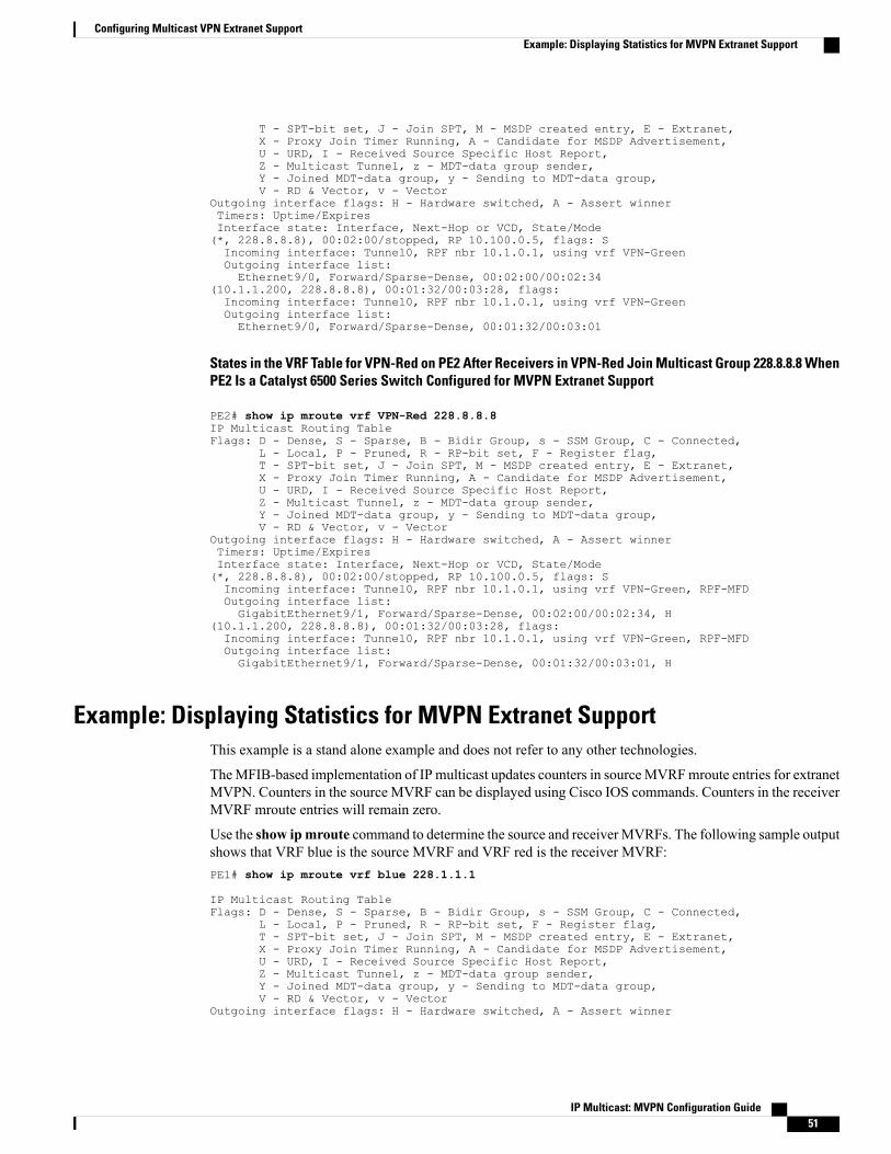
T - SPT-bit set, J - Join SPT, M - MSDP created entry, E - Extranet,X - Proxy Join Timer Running, A - Candidate for MSDP Advertisement,U - URD, I - Received Source Specific Host Report,Z - Multicast Tunnel, z - MDT-data group sender,Y - Joined MDT-data group, y - Sending to MDT-data group,V - RD & Vector, v - Vector
Outgoing interface flags: H - Hardware switched, A - Assert winnerTimers: Uptime/ExpiresInterface state: Interface, Next-Hop or VCD, State/Mode(*, 228.8.8.8), 00:02:00/stopped, RP 10.100.0.5, flags: SIncoming interface: Tunnel0, RPF nbr 10.1.0.1, using vrf VPN-GreenOutgoing interface list:Ethernet9/0, Forward/Sparse-Dense, 00:02:00/00:02:34
(10.1.1.200, 228.8.8.8), 00:01:32/00:03:28, flags:Incoming interface: Tunnel0, RPF nbr 10.1.0.1, using vrf VPN-GreenOutgoing interface list:Ethernet9/0, Forward/Sparse-Dense, 00:01:32/00:03:01
States in the VRF Table for VPN-Red on PE2 After Receivers in VPN-Red Join Multicast Group 228.8.8.8 WhenPE2 Is a Catalyst 6500 Series Switch Configured for MVPN Extranet Support
PE2# show ip mroute vrf VPN-Red 228.8.8.8IP Multicast Routing TableFlags: D - Dense, S - Sparse, B - Bidir Group, s - SSM Group, C - Connected,
L - Local, P - Pruned, R - RP-bit set, F - Register flag,T - SPT-bit set, J - Join SPT, M - MSDP created entry, E - Extranet,X - Proxy Join Timer Running, A - Candidate for MSDP Advertisement,U - URD, I - Received Source Specific Host Report,Z - Multicast Tunnel, z - MDT-data group sender,Y - Joined MDT-data group, y - Sending to MDT-data group,V - RD & Vector, v - Vector
Outgoing interface flags: H - Hardware switched, A - Assert winnerTimers: Uptime/ExpiresInterface state: Interface, Next-Hop or VCD, State/Mode(*, 228.8.8.8), 00:02:00/stopped, RP 10.100.0.5, flags: SIncoming interface: Tunnel0, RPF nbr 10.1.0.1, using vrf VPN-Green, RPF-MFDOutgoing interface list:GigabitEthernet9/1, Forward/Sparse-Dense, 00:02:00/00:02:34, H
(10.1.1.200, 228.8.8.8), 00:01:32/00:03:28, flags:Incoming interface: Tunnel0, RPF nbr 10.1.0.1, using vrf VPN-Green, RPF-MFDOutgoing interface list:GigabitEthernet9/1, Forward/Sparse-Dense, 00:01:32/00:03:01, H
Example: Displaying Statistics for MVPN Extranet SupportThis example is a stand alone example and does not refer to any other technologies.
TheMFIB-based implementation of IP multicast updates counters in sourceMVRFmroute entries for extranetMVPN. Counters in the source MVRF can be displayed using Cisco IOS commands. Counters in the receiverMVRF mroute entries will remain zero.
Use the show ipmroute command to determine the source and receiverMVRFs. The following sample outputshows that VRF blue is the source MVRF and VRF red is the receiver MVRF:PE1# show ip mroute vrf blue 228.1.1.1
IP Multicast Routing TableFlags: D - Dense, S - Sparse, B - Bidir Group, s - SSM Group, C - Connected,
L - Local, P - Pruned, R - RP-bit set, F - Register flag,T - SPT-bit set, J - Join SPT, M - MSDP created entry, E - Extranet,X - Proxy Join Timer Running, A - Candidate for MSDP Advertisement,U - URD, I - Received Source Specific Host Report,Z - Multicast Tunnel, z - MDT-data group sender,Y - Joined MDT-data group, y - Sending to MDT-data group,V - RD & Vector, v - Vector
Outgoing interface flags: H - Hardware switched, A - Assert winner
IP Multicast: MVPN Configuration Guide 51
Configuring Multicast VPN Extranet SupportExample: Displaying Statistics for MVPN Extranet Support
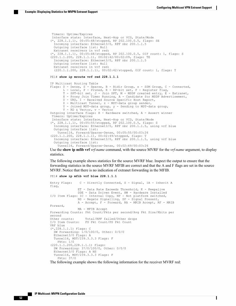
Timers: Uptime/ExpiresInterface state: Interface, Next-Hop or VCD, State/Mode(*, 228.1.1.1), 00:05:48/stopped, RP 202.100.0.5, flags: SEIncoming interface: Ethernet3/0, RPF nbr 200.1.1.5Outgoing interface list: NullExtranet receivers in vrf red:
(*, 228.1.1.1), 00:05:48/stopped, RP 202.100.0.5, OIF count: 1, flags: S(220.1.1.200, 228.1.1.1), 00:02:42/00:02:09, flags: TEIncoming interface: Ethernet3/0, RPF nbr 200.1.1.5Outgoing interface list: NullExtranet receivers in vrf red:(220.1.1.200, 228.1.1.1), 00:02:42/stopped, OIF count: 1, flags: T
PE1# show ip mroute vrf red 228.1.1.1
IP Multicast Routing TableFlags: D - Dense, S - Sparse, B - Bidir Group, s - SSM Group, C - Connected,
L - Local, P - Pruned, R - RP-bit set, F - Register flag,T - SPT-bit set, J - Join SPT, M - MSDP created entry, E - Extranet,X - Proxy Join Timer Running, A - Candidate for MSDP Advertisement,U - URD, I - Received Source Specific Host Report,Z - Multicast Tunnel, z - MDT-data group sender,Y - Joined MDT-data group, y - Sending to MDT-data group,V - RD & Vector, v - Vector
Outgoing interface flags: H - Hardware switched, A - Assert winnerTimers: Uptime/ExpiresInterface state: Interface, Next-Hop or VCD, State/Mode(*, 228.1.1.1), 00:05:55/stopped, RP 202.100.0.5, flags: SIncoming interface: Ethernet3/0, RPF nbr 200.1.1.5, using vrf blueOutgoing interface list:Tunnel16, Forward/Sparse-Dense, 00:05:55/00:03:26
(220.1.1.200, 228.1.1.1), 00:02:49/stopped, flags: TIncoming interface: Ethernet3/0, RPF nbr 200.1.1.5, using vrf blueOutgoing interface list:Tunnel16, Forward/Sparse-Dense, 00:02:49/00:03:26
Use the show ip mfib vrf vrf-name command, with the source MVRF for the vrf-name argument, to displaystatistics.
The following example shows statistics for the source MVRF blue. Inspect the output to ensure that theforwarding statistics in the source MVRF MFIB are correct and that the A and F flags are set in the sourceMVRF. Notice that there is no indication of extranet forwarding in the MFIB.PE1# show ip mfib vrf blue 228.1.1.1
Entry Flags: C - Directly Connected, S - Signal, IA - Inherit Aflag,
ET - Data Rate Exceeds Threshold, K - KeepaliveDDE - Data Driven Event, HW - Hardware Installed
I/O Item Flags: IC - Internal Copy, NP - Not platform switched,NS - Negate Signalling, SP - Signal Present,A - Accept, F - Forward, RA - MRIB Accept, RF - MRIB
Forward,MA - MFIB Accept
Forwarding Counts: Pkt Count/Pkts per second/Avg Pkt Size/Kbits persecondOther counts: Total/RPF failed/Other dropsI/O Item Counts: FS Pkt Count/PS Pkt CountVRF blue(*,228.1.1.1) Flags: CSW Forwarding: 1/0/100/0, Other: 0/0/0Ethernet3/0 Flags: ATunnel16, MDT/239.3.3.3 Flags: FPkts: 1/0
(220.1.1.200,228.1.1.1) Flags:SW Forwarding: 37/0/100/0, Other: 0/0/0Ethernet3/0 Flags: A NSTunnel16, MDT/239.3.3.3 Flags: FPkts: 37/0
The following example shows the following information for the receiver MVRF red:
IP Multicast: MVPN Configuration Guide52
Configuring Multicast VPN Extranet SupportExample: Displaying Statistics for MVPN Extranet Support

• There are no forwarding statistics in the receiver MVRF MFIB because these statistics are collected inthe source MVRF.
• The A and F flags are not set because these flags are only set in the source MVRF for MVPN extranet.
• There is no indication of extranet forwarding in the MFIB.
The NS flag in the output is present for the purpose of receiving PIM control traffic in the receiver MVRF.Note
PE1# show ip mfib vrf red 228.1.1.1
Entry Flags: C - Directly Connected, S - Signal, IA - Inherit Aflag,
ET - Data Rate Exceeds Threshold, K - KeepaliveDDE - Data Driven Event, HW - Hardware Installed
I/O Item Flags: IC - Internal Copy, NP - Not platform switched,NS - Negate Signalling, SP - Signal Present,A - Accept, F - Forward, RA - MRIB Accept, RF - MRIB
Forward,MA - MFIB Accept
Forwarding Counts: Pkt Count/Pkts per second/Avg Pkt Size/Kbits persecondOther counts: Total/RPF failed/Other dropsI/O Item Counts: FS Pkt Count/PS Pkt CountVRF red(*,228.1.1.1) Flags: CSW Forwarding: 0/0/0/0, Other: 0/0/0Tunnel16, MDT/239.3.3.3 Flags: NS
(220.1.1.200,228.1.1.1) Flags:SW Forwarding: 0/0/0/0, Other: 0/0/0
Tunnel16, MDT/239.3.3.3 Flags: NS
You can also use the show ip mroute count command to display the extranet MVPN statistics. However, werecommend that you use the show ip mfib command instead. If you use the show ip mroute countcommandto display statistics, inspect the output to ensure that the forwarding statistics in the source MVRF are correctand that there are no forwarding statistics in the receiver MVRF.
The following sample output from the show ipmroute count command shows statistics for the sourceMVRFblue:
PE1# show ip mroute vrf blue 228.1.1.1 count
Use "show ip mfib count" to get better response time for a large number ofmroutes.
IP Multicast Statistics3 routes using 1354 bytes of memory2 groups, 0.50 average sources per groupForwarding Counts: Pkt Count/Pkts per second/Avg Pkt Size/Kilobits per secondOther counts: Total/RPF failed/Other drops(OIF-null, rate-limit etc)Group: 228.1.1.1, Source count: 1, Packets forwarded: 38, Packets received: 38RP-tree: Forwarding: 1/0/100/0, Other: 1/0/0Source: 220.1.1.200/32, Forwarding: 37/0/100/0, Other: 37/0/0
The following sample output from the show ip mroute count command is for the receiver MVRF red:PE1# show ip mroute vrf red 228.1.1.1 count
Use "show ip mfib count" to get better response time for a large number ofmroutes.
IP Multicast Statistics3 routes using 1672 bytes of memory2 groups, 0.50 average sources per groupForwarding Counts: Pkt Count/Pkts per second/Avg Pkt Size/Kilobits per secondOther counts: Total/RPF failed/Other drops(OIF-null, rate-limit etc)Group: 228.1.1.1, Source count: 1, Packets forwarded: 0, Packets received: 0
IP Multicast: MVPN Configuration Guide 53
Configuring Multicast VPN Extranet SupportExample: Displaying Statistics for MVPN Extranet Support

RP-tree: Forwarding: 0/0/0/0, Other: 0/0/0Source: 220.1.1.200/32, Forwarding: 0/0/0/0, Other: 0/0/0
Example Configuring RPF for MVPN Extranet Support Using Static MroutesThe following example shows how to configure the RPF lookup originating in VPN-Red to be resolved inVPN-Green using the static mroute 192.168.1.1:
ip mroute vrf VPN-Red 192.168.1.1 255.255.255.255 fallback-lookup vrf VPN-Green
Example Configuring Group-Based VRF Selection Policies with MVPN ExtranetSupport
The following example shows how to use group-based VRF selection policies to configure RPF lookupsoriginating in VPN-Green to be performed in VPN-Red for group addresses that match ACL 1 and to beperformed in VPN-Blue for group addresses that match ACL 2.
ip multicast vrf VPN-Green rpf select vrf VPN-Red group-list 1ip multicast vrf VPN-Green rpf select vrf VPN-Blue group-list 2!...!access-list 1 permit 239.0.0.0 0.255.255.255access-list 2 permit 238.0.0.0 0.255.255.255!
Example: Group-Based VRF Selection Policies with MVPNv6 ExtranetThe following example shows how to use a group-based VRF selection policy to configure the RPF lookupfor groups that match ACL 1 to be performed in VPN-blue:ipv6 multicast vrf VPN-red rpf select vrf VPN-blue group-range 1!...!access-list 1 permit ff02::00 00f0::00!
Additional ReferencesRelated Documents
Document TitleRelated Topic
“ Configuring Basic IP Multicast ” moduleBasic IP multicast concepts, configuration tasks, andexamples
IP Multicast: MVPN Configuration Guide54
Configuring Multicast VPN Extranet SupportExample Configuring RPF for MVPN Extranet Support Using Static Mroutes
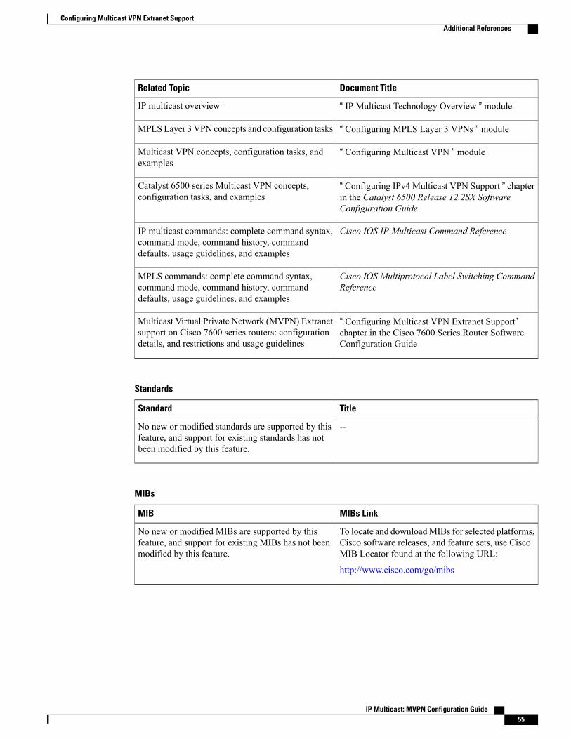
Document TitleRelated Topic
“ IP Multicast Technology Overview ” moduleIP multicast overview
“ Configuring MPLS Layer 3 VPNs ” moduleMPLS Layer 3 VPN concepts and configuration tasks
“ Configuring Multicast VPN ” moduleMulticast VPN concepts, configuration tasks, andexamples
“ Configuring IPv4 Multicast VPN Support ” chapterin the Catalyst 6500 Release 12.2SX SoftwareConfiguration Guide
Catalyst 6500 series Multicast VPN concepts,configuration tasks, and examples
Cisco IOS IP Multicast Command ReferenceIP multicast commands: complete command syntax,command mode, command history, commanddefaults, usage guidelines, and examples
Cisco IOS Multiprotocol Label Switching CommandReference
MPLS commands: complete command syntax,command mode, command history, commanddefaults, usage guidelines, and examples
“ Configuring Multicast VPN Extranet Support”chapter in the Cisco 7600 Series Router SoftwareConfiguration Guide
Multicast Virtual Private Network (MVPN) Extranetsupport on Cisco 7600 series routers: configurationdetails, and restrictions and usage guidelines
Standards
TitleStandard
--No new or modified standards are supported by thisfeature, and support for existing standards has notbeen modified by this feature.
MIBs
MIBs LinkMIB
To locate and downloadMIBs for selected platforms,Cisco software releases, and feature sets, use CiscoMIB Locator found at the following URL:
http://www.cisco.com/go/mibs
No new or modified MIBs are supported by thisfeature, and support for existing MIBs has not beenmodified by this feature.
IP Multicast: MVPN Configuration Guide 55
Configuring Multicast VPN Extranet SupportAdditional References

RFCs
TitleRFC
--No new or modified RFCs are supported by thisfeature, and support for existing RFCs has not beenmodified by this feature.
Technical Assistance
LinkDescription
http://www.cisco.com/cisco/web/support/index.htmlThe Cisco Support website provides extensive onlineresources, including documentation and tools fortroubleshooting and resolving technical issues withCisco products and technologies.
To receive security and technical information aboutyour products, you can subscribe to various services,such as the Product Alert Tool (accessed from FieldNotices), the Cisco Technical Services Newsletter,and Really Simple Syndication (RSS) Feeds.
Access to most tools on the Cisco Support websiterequires a Cisco.com user ID and password.
Feature Information for Configuring Multicast VPN ExtranetSupport
The following table provides release information about the feature or features described in this module. Thistable lists only the software release that introduced support for a given feature in a given software releasetrain. Unless noted otherwise, subsequent releases of that software release train also support that feature.
Use Cisco Feature Navigator to find information about platform support and Cisco software image support.To access Cisco Feature Navigator, go to www.cisco.com/go/cfn. An account on Cisco.com is not required.
IP Multicast: MVPN Configuration Guide56
Configuring Multicast VPN Extranet SupportFeature Information for Configuring Multicast VPN Extranet Support

Table 2: Feature Information for Configuring Multicast VPN Extranet Support
Feature InformationReleasesFeature Name
The Multicast VPN ExtranetSupport feature enables serviceproviders to distribute IP multicastcontent originated from oneenterprise site to other enterprisesites. This feature enables serviceproviders to offer the nextgeneration of flexible extranetservices, helping to enable businesspartnerships between differententerprise VPN customers.
In Cisco IOS XE Release 3.8S,support was added for the CiscoISR 4400 Series Routers.
In Cisco IOS XE Release 3.9S,support was added for the CiscoCSR 1000V.
The following commands wereintroduced or modified by thisfeature: ip mroute, show ipmroute.
12.2(31)SB2
12.2(33)SXH
12.2(33)SRC
Cisco IOS XE Release 2.5
15.0(1)M
15.0(1)S
Cisco IOS XE Release 3.8S
Cisco IOS XE Release 3.9S
Cisco IOS Release 15.4(1)T
Multicast VPN Extranet Support
The Multicast VPN Extranet VRFSelect feature provides thecapability for RPF lookups to beperformed to the same sourceaddress in different VRFs using thegroup address as the VRF selector.This feature enhances extranetMVPNs by enabling serviceproviders to distribute contentstreams coming in from differentMVPNs and redistributing themfrom there.
The following commands wereintroduced or modified by thisfeature: ip multicast rpf select,show ip rpf, show ip rpf select.
12.2(31)SB2
Cisco IOS XE Release 2.5
15.0(1)M
Multicast VPN Extranet VRFSelect
IP Multicast: MVPN Configuration Guide 57
Configuring Multicast VPN Extranet SupportFeature Information for Configuring Multicast VPN Extranet Support

Feature InformationReleasesFeature Name
The Hardware Acceleration forMulticast VPN Extranet Supportfeature introduces the linking offorwarding entries and thereplication of packets in hardwarefor extranet MVPN services onCatalyst 6500 series switches.
In 12.2(33)SXH, this feature wasintroduced on Catalyst 6500 seriesswitches.
12.2(33)SXHHardware Acceleration forMulticast VPN Extranet Support
This feature enables serviceproviders to forward IPv6multicasttraffic across VRF boundaries ona PE device.
The following commands wereintroduced or modified by thisfeature: ipv6 icast rpf select, showipv6 rpf.
15.3(1)S
Cisco IOS Release 15.4(1)T
MVPNv6 Extranet
IP Multicast: MVPN Configuration Guide58
Configuring Multicast VPN Extranet SupportFeature Information for Configuring Multicast VPN Extranet Support

C H A P T E R 4Configuring Multicast VPN Inter-AS Support
TheMulticast VPN Inter-AS Support feature enablesMulticast Distribution Trees (MDTs) used forMulticastVPNs (MVPNs) to span multiple autonomous systems. Benefits include increased multicast coverage tocustomers that require multicast to span multiple service providers in a Multiprotocol Label Switching(MPLS) Layer 3 Virtual Private Network (VPN) service with the flexibility to support all options describedin RFC 4364. Additionally, theMulticast VPN Inter-AS Support feature can be used to consolidate an existingMVPN service with another MVPN service, such as the case with a company merger or acquisition.
• Finding Feature Information, page 59
• Prerequisites for Configuring Multicast VPN Inter-AS Support, page 59
• Restrictions for Configuring Multicast VPN Inter-AS Support, page 60
• Information About Multicast VPN Inter-AS Support, page 60
• How to Configure Multicast VPN Inter-AS Support, page 77
• Configuration Examples for Multicast VPN Inter-AS Support, page 88
• Additional References, page 118
• Feature Information for Configuring Multicast VPN Inter-AS Support, page 119
Finding Feature InformationYour software release may not support all the features documented in this module. For the latest caveats andfeature information, see Bug Search Tool and the release notes for your platform and software release. Tofind information about the features documented in this module, and to see a list of the releases in which eachfeature is supported, see the feature information table.
Use Cisco Feature Navigator to find information about platform support and Cisco software image support.To access Cisco Feature Navigator, go to www.cisco.com/go/cfn. An account on Cisco.com is not required.
Prerequisites for Configuring Multicast VPN Inter-AS Support• You understand IP multicast concepts and configuration tasks.
IP Multicast: MVPN Configuration Guide 59

• You understand MVPN concepts and configuration tasks.
• You understand Border Gateway Protocol (BGP) concepts and configuration tasks.
• You understand MPLS Layer 3 VPN concepts and configuration tasks.
Restrictions for Configuring Multicast VPN Inter-AS SupportThe Multicast VPN Inter-AS Support feature requires that all routers in the core be configured for ProtocolIndependent Multicast (PIM) Source Specific Multicast (SSM). Protocol Independent Multicast sparse mode(PIM-SM) and bidirectional PIM (bidir-PIM) are not supported.
Information About Multicast VPN Inter-AS Support
MVPN Inter-AS Support OverviewAs a general concept, MVPN inter-AS support enables service providers to provide multicast connectivity toVPN sites that span multiple autonomous systems. There are two types of MVPN inter-AS deploymentscenarios:
• Single provider inter-AS--A service provider whose internal network consists of multiple autonomoussystems.
• Intraprovider inter-AS--Multiple service providers that need to coordinate their networks to provideinter-AS support.
The extensions added to support the Multicast VPN Inter-AS Support feature enable MDTs used for MVPNsto span multiple autonomous systems.
Benefits of MVPN Inter-AS SupportThe MVPN Inter-AS Support feature provides the following benefits to service providers:
• Increased multicast coverage to customers that require multicast to span multiple services providers inan MPLS Layer 3 VPN service with the flexibility to support all options described in RFC 4364.
• The ability to consolidate an existing MVPN service with another MVPN service, such as the case witha company merger or acquisition.
MVPN Inter-AS Support Implementation RequirementsTheMulticast VPN Inter-AS Support feature was implemented in the software in accordance to the followingrequirements:
• To achieve parity with unicast inter-AS support, the software must support the following inter-AS optionsfor MVPN (as defined in RFC 4364):
IP Multicast: MVPN Configuration Guide60
Configuring Multicast VPN Inter-AS SupportRestrictions for Configuring Multicast VPN Inter-AS Support

Option A--Back-to-back VPN routing and forwarding (VRF) instances at the Autonomous SystemBorder Router (ASBR) provider edge (PE) routers
•
The Option A model assumes direct connectivity between PE routers of different autonomous systems. ThePE routers are attached by multiple physical or logical interfaces, each of which is associated with a givenVPN (through a VRF instance). Each PE router, therefore, treats the adjacent PE router like a customer edge(CE) router, and the standard Layer 3 MPLS VPN mechanisms are used for route redistribution with eachautonomous system; that is, the PEs use exterior BGP (eBGP) to distribute unlabeled IPv4 addresses to eachother.
Option A allows service providers to isolate each autonomous system from the other, which providesbetter control over routing exchanges and security between the two networks. Option A, however, isconsidered the least scalable of all the inter-AS connectivity options.
Note
• Option B--VPNv4 route exchange between ASBRs•
In the Option B model, the PE routers use interior BGP (iBGP) to redistribute labeled VPNv4 routes eitherto an ASBR or to a route reflector of which an ASBR is a client. ASBRs then use multiprotocol eBGP(MP-eBGP) to advertise VPNv4 routes into the local autonomous system.
MP-eBGP provides the functionality to advertise VPNv4 prefix and label information across the serviceprovider boundaries. The advertising ASBR router replaces the two-level label stack (which it uses to reachthe originating PE router and VPN destination in the local autonomous system) with a locally allocated labelbefore advertising the VPNv4 route. This replacement is necessary because the next-hop attribute of all routesadvertised between the two service providers is reset to the ASBR router’s peering address, so the ASBRrouter becomes the termination point of the label-switched path (LSP) for the advertised routes. To preservethe LSP between ingress and egress PE routers, the ASBR router must allocate a local label that may be usedto identify the label stack of the route within the local VPN network. This newly allocated label is set onpackets sent toward the prefix from the adjacent service provider.
Option B enables service providers to isolate both autonomous systems with the added advantage that itscales to a higher degree than Option A.
Note
• Option C--Exchange of VPNv4 routes between route reflectors (RRs) usingmultihop eBGP peeringsessions
•
The Option C model combines MP-eBGP exchange of VPNv4 routes between RRs of different autonomoussystems with the next hops for these routes exchanged between corresponding ASBR routers. In the OptionC model, VPNv4 routes are neither maintained nor distributed by the ASBRs. ASBRs must maintain labeledIPv4 /32 routes to the PE routers within its autonomous system and use eBGP to distribute these routes toother autonomous systems. ASBRs in any transit autonomous systems will also have to use eBGP to passalong the labeled /32 routes. The result is the creation of a LSP from the ingress PE router to the egress PErouter.
Because RRs of different autonomous systems will not be directly connected, multihop functionality is requiredto allow for the establishment of the MP-eBGP peering sessions. The exchange of next hops is necessarybecause the RRs do not reset the next-hop attribute of the VPNv4 routes when advertising them to adjacent
IP Multicast: MVPN Configuration Guide 61
Configuring Multicast VPN Inter-AS SupportMVPN Inter-AS Support Implementation Requirements

autonomous systems because they do not want to attract the traffic for the destinations that they advertise.They are not the original endpoint--just a relay station between the source and receiver PEs. The PE routernext-hop addresses for the VPNv4 routes, thus, are exchanged between ASBR routers. The exchange of theseaddresses between autonomous systems can be accomplished by redistributing the PE router /32 addressesbetween the autonomous systems or by using BGP label distribution.
Option C normally is deployed only when each autonomous system belongs to the same overall authority,such as a global Layer 3 MPLS VPN service provider with autonomous systems in different regions ofthe world. Option B is equally suited for this purpose and is also deployed in networks where autonomybetween different regions is desired.
Note
• The Cisco software must support inter-AS MDTs. An inter-AS MDT is an MDT that extends acrossautonomous system boundaries. In the context of MVPN, because MVPN packets are encapsulatedwhen being forwarded between ASBRs, an inter-AS MDT is needed (for Option B and Option C) toextend the MDT across the boundaries of the autonomous system.
Limitations That Prevented Option B and Option C SupportPrior to the extensions introduced in association with theMulticast VPN Inter-AS Support feature, limitationsexisted that prevented MVPN inter-AS support for Option B and Option C. These limitations were related tothe following areas:
• Supporting reverse path forwarding (RPF) for inter-AS sources (applicable mainly to Option B)
•When a PE router sends a PIM join (source PE address, MDT group address) for the default MDT,each P router in the path between the source and the destination PE routers must perform an RPFcheck on the source. Because Interior Gateway Protocol (IGP) routes (which would include theroutes to source PE routers in remote autonomous systems) are not leaked across autonomoussystems, the P routers in the receiving autonomous system were unable to perform an RPF check.
•When a PIM join is received in an MVPN, an IP lookup is performed in the VRF to find the nexthop toward the destination. This destination must be a PIM neighbor that can be reached throughthe MDT tunnel interface. However, because ASBRs change the next hop of the originating PErouter for a given MDT group, the originating source address would be lost, and the RPF check atthe PE router would fail.
In typical Option C inter-AS deployments, the limitation related to supporting RPF for MVPN inter-ASsupport was not applicable because the RRs store all VPNv4 routes.
Note
• Supporting an inter-AS MDT (applicable to Option B and Option C)
• The default MDT relies on the ability of the PE routers to join the default multicast group. Thesource of the group is the originating PE router address used for MP-BGP peering. Prior to theextensions introduced in association with theMulticast VPN Inter-AS Support feature, this addresscould not be reached between autonomous systems because IGP routes could not be distributedacross the autonomous systems. The default MDT for inter-AS MVPN, thus, could not beestablished.
IP Multicast: MVPN Configuration Guide62
Configuring Multicast VPN Inter-AS SupportMVPN Inter-AS Support Implementation Requirements

MVPN Inter-AS Support for Option AThe limitations that prevented support for MVPN inter-AS support Options B and C have never applied toOption A for the following reasons:
• For Option A, native IP forwarding is used by the PE routers between autonomous systems; therefore,Option A does not require support for inter-AS MDTs.
• For Option A, the MDT is limited to one autonomous system; therefore, the issues associated withmanaging MDT group addresses between autonomous systems and RPF for inter-AS sources neverapplied to Option A.
Because Option A requires that one physical or logical interface be configured for each VRF, Option Ais considered the least scalable MVPN inter-AS solution.
Note
MVPN Inter-AS Support Solution for Options B and CThe following extensions introduced in association with the MVPN Inter-AS Support feature resolve theMVPN inter-AS protocol limitations related to supporting RPF and inter-AS MDTs in Option B and Cdeployments:
• BGP connector attribute inMP-BGP--This attribute helps preserve the identity of a PE router originatinga VPNv4 prefix. This BGP extension helps solve the challenge of supporting RPF to sources in a remoteautonomous system.
• BGP MDT Subaddress Family Identifier (SAFI)--This identifier helps ASBRs RPF to source PEs in aremote autonomous systems. The BGP MDT SAFI also helps ASBRs and receiver PEs insert the RPFVector needed to build an inter-AS MDT to source PEs in remote autonomous systems.
BGP Connector AttributeIn an adjacent autonomous system, a PE router that wants to join a particular source of the default MDT fora given MVPN must know the originator’s address of the source PE router. This presents some challenges forOption B inter-AS deployments because the originator next hop for VPNv4 routes is rewritten at one or morepoints in the network. To solve this limitation, each VPNv4 route must carry a new attribute (the BGP connectorattribute) that defines the route’s originator.The BGP connector attribute is a transitive attribute that stores the PE router that originated a VPNv4 prefix.In a local autonomous system, the BGP connector attribute is the same as the next hop attribute. Whenadvertised to other ASBRs in VPNv4 advertisements (as is the case in Option B), the value of the BGPconnector attribute is preserved even after the next hop attribute is rewritten by ASBRs. The BGP connectorattribute is a critical component of the MVPN inter-AS solution, helping to enable RPF to sources in remoteautonomous systems.
IP Multicast: MVPN Configuration Guide 63
Configuring Multicast VPN Inter-AS SupportMVPN Inter-AS Support Solution for Options B and C

The BGP connector attribute also helps ASBRs and receiver PEs insert the RPF Vector needed to buildthe inter-ASMDT for source PEs in remote autonomous systems. For more information about RPFVectors,see the PIM RPF Vector, on page 65 section.
Note
The format of the BGP connector attribute is shown in the figure.
Figure 11: BGP Connector Attribute
BGP MDT SAFI Updates for MVPN Inter-AS SupportThe BGPMDT SAFI is specifically designed to carry the address of the source PE router to which a PIM joinshould be sent for the MDT group contained in the PIM join. The format of the Network Layer ReachabilityInformation (NLRI) carried in this SAFI is {RD:PE-IP-address}. The BGP MDT SAFI is capable of beingadvertised across autonomous system boundaries. Each MDT group is carried in the MP_REACH attributeusing the format shown in the figure.
Figure 12: MDT SAFI Format
When RRs and MP-eBGP peerings are used, the advertisement of the BGP MDT SAFI is independent of theadvertisement of VPNv4 routes. BGP MDT SAFI advertisements, however, are processed and filtered likeVPNv4 advertisements.
ASBRs store the path advertised in BGP MDT SAFI updates in a separate table. How the BGP MDT SAFIis advertised determines the RPF path to the PE router that originated the advertisement.
IP Multicast: MVPN Configuration Guide64
Configuring Multicast VPN Inter-AS SupportMVPN Inter-AS Support Solution for Options B and C

PEs also store the BGP MDT SAFI update in a separate table. PE routers use the information contained inthe BGP MDT SAFI to determine the ASBR that is the exit router to the source PE router in an adjacentautonomous system.
PIM RPF VectorNormally, in an MVPN environment, PIM sends join messages containing the IP address of upstream PErouters that are sources of a given MDT group. To be able to perform RPF checks, however, P routers musthave IPv4 reachability to source PE routers in remote autonomous systems. This behavior is not the case withinter-ASOptions B and C because the autonomous systems do not exchange any of their IGP routes, includingthose of their local PE routers. However, P routers do have reachability to the BGP next hop of the BGPMDTupdate received with the BGP MDT SAFI updates at the PE routers. Therefore, if the PE routers add theremote PE router IP address (as received within the BGP MDT SAFI) and the BGP next-hop address of thisaddress within the PIM join, the P routers can perform an RPF check on the BGP next-hop address ratherthan the original PE router address, which, in turn, allows the P router to forward the join toward the ASBRthat injected the MDT SAFI updates for a remote autonomous system. This functionality is generally referredto as the PIM RPF Vector ; the actual vector that is inserted into PIM joins is referred to as the RPF Vectoror the Proxy Vector . The PIM RPF Vector, therefore, enables P routers to determine the exit ASBR to asource PE router in a remote autonomous system. Having received the join that contains a RPF Vector, anASBR can then determine that the next-hop address is in fact itself and can perform an RPF check based onthe originating PE router address carried in the PIM join.
When configured on PE routers using the ipmulticast rpf proxy vector command, the RPFVector is encodedas a part of the source address in PIM join and prune messages. The RPF Vector is the IGP next hop for PIMRPF neighbor in PIM join and prune messages, which is typically the exit ASBR router to a prefix in a remoteautonomous system.
The format of this PIM RPF Vector encoding in PIM join and prune messages is shown in the figure.
Figure 13: PIM RPF Vector Encoded in PIM Join and Prune Messages
RPF Vectors can be used natively in an IP environment (that is, in a non-VPN environment). For moreinformation about the use of RPF Vectors in a native environment, see RFC 5496, The Reverse PathForwarding (RPF) Vector TLV .
Note
Originators of an RPF Vector
Whether or not a PE router originates an RPF Vector is determined by configuration; that is, the ip multicastrpf proxy vector command must be configured on all PE routers in order for an RPF Vector to be originated.The PE router that originates an RPF Vector always performs an RPF lookup on the source. When a PE router
IP Multicast: MVPN Configuration Guide 65
Configuring Multicast VPN Inter-AS SupportMVPN Inter-AS Support Solution for Options B and C

performs an RPF lookup on a source, the PE router learns the origin of an RPF Vector in one of the followingways:
• In an MVPN network environment, the RPF Vector is learned from BGP MDT SAFI updates.
• In a native IP network environment, the RPF Vector is learned from either IP unicast routing (AFI=1,SAFI=1) or IP multicast reverse-path information (AFI=1, SAFI=2).
For more information about the use of RPF Vectors in a native environment, see RFC 5496, The ReversePath Forwarding (RPF) Vector TLV .
Note
Routers that understand the RPF Vector format advertise the RPF Vector in PIM hello messages.Note
Recipients of an RPF Vector
When a router receives a PIM join that contains an RPF Vector, that router stores the RPF Vector so that itcan generate a PIM join to the exit ASBR router. P routers, thus, learn the RPF Vector from PIM joins. TheRPF Vector is advertised to all P routers in the core. If multiple RPF Vectors are received by a router, theRPF Vector with the lower originator address is used. When the RPF Vector is present, it takes priority; as aresult, RPF checks are triggered periodically to readvertise RPF Vectors upstream. If a router receives an RPFVector that references a local interface (typically an ASBR), the RPF Vector is discarded and a normal RPFlookup is performed.
ASBR Receipt of an RPF Vector
When an ASBR receives an RPF Vector, it typically references a local interface (most likely a loopbackinterface); in which case, the RPF Vector is discarded and a normal RPF lookup is performed. If the RD typeis 2, the ASBR performs an RPF lookup in the BGPMDT table that is built from the BGPMDT SAFI updates;this type of RPF lookup uses both the RD and the source PE address contained in the PIM join.
Interoperability with RPF Vector
A new PIM hello option is introduced along with the PIM RPF Vector extension to determine if the upstreamrouter is capable of parsing the new encoding. An RPF Vector is included in PIM messages only when allPIM neighbors on an RPF interface support it.
MDT Address Family in BGP for Multicast VPN Inter-AS SupportThemdt keyword has been added to the address-family ipv4 command to configure anMDT address-familysession.
Supported Policy
The following policy configuration parameters are supported under the BGP MDT SAFI:
IP Multicast: MVPN Configuration Guide66
Configuring Multicast VPN Inter-AS SupportMVPN Inter-AS Support Solution for Options B and C

• Mandatory attributes and well-known attributes, such as the AS-path, multi-exit discriminator MED,BGP local-preference, and next hop attributes.
• Standard communities, community-lists, and route-maps.
Guidelines for Configuring MDT Address Family Sessions on PE Routers for MVPN Inter-AS Support
When configuring routers for MVPN inter-AS support, follow these guidelines:
• For MVPN inter-AS Option A, BGP MDT address-family peering sessions are not required betweenthe PE routers because native IP forwarding is used by the PE routers. For option A, BGPMDT peeringsessions are only required for intra-AS VPN peering sessions.
• For MVPN inter-AS Option B, BGP MDT address-family peering sessions are only required betweenthe PEs and ASBRs. In the Option B inter-AS case where PE routers use iBGP to redistribute labeledVPNv4 routes to RRs of which ASBRs are clients, then BGP MDT address-family peering sessions arerequired between the PEs, ASBRs, and RRs.
• For MVPN inter-AS Option C, BGP MDT address-family peering sessions are only required betweenthe PEs and RRs.
MVPN Inter-AS MDT Establishment for Option BThis section describes the sequence of events that leads to the establishment of an inter-AS MDT betweenthe autonomous systems in the sample inter-AS Option B topology illustrated in the following figure. For thistopology, assume that all the routers have been configured properly to support all extensions associated withthe Multicast VPN Inter-AS Support feature.
Figure 14: MVPN Inter-AS Support Option B Sample Topology
The following sequence of events occur to establish an MDT default tree rooted at PE1B in this inter-ASMVPN Option B topology:
IP Multicast: MVPN Configuration Guide 67
Configuring Multicast VPN Inter-AS SupportMVPN Inter-AS MDT Establishment for Option B

1 As illustrated in the following figure, PE1B advertises the default MDT information for VPN blue usingthe BGP MDT SAFI with itself (PE1B) as the next hop.
Figure 15: BGP Updates from PE1B to ASBR1B
1 As illustrated in the following figure, ASBR1B receives theMDT SAFI information and, in turn, advertisesthis information to ASBR1A with itself (ASBR1B) as the next hop.
Figure 16: BGP Updates from ASBR1B to ASBR1A
IP Multicast: MVPN Configuration Guide68
Configuring Multicast VPN Inter-AS SupportMVPN Inter-AS MDT Establishment for Option B

1 As illustrated in the following figure, ASBR1A advertises the MDT SAFI to PE1A with itself (ASBR1A)as the next hop.
Figure 17: BGP Updates from ASBR1A to PE1A
1 As illustrated in the following figure, PE1A learns the source PE router, the RD, and the default MDTgroup address from BGPMDT SAFI updates. In addition, from the same BGPMDT SAFI updates, PE1Alearns that the RPF Vector, ASBR1A, is the exit router to source PE1B RD 55:1111. PE1A learns that
IP Multicast: MVPN Configuration Guide 69
Configuring Multicast VPN Inter-AS SupportMVPN Inter-AS MDT Establishment for Option B

P1A is an RPF neighbor through an IGP. PE1A then inserts the RPF Vector into the PIM join and sendsthe PIM join that is destined for source PE1B to P1A.
Figure 18: SSM Default PIM Join from PE1A to P1A
IP Multicast: MVPN Configuration Guide70
Configuring Multicast VPN Inter-AS SupportMVPN Inter-AS MDT Establishment for Option B

1 As illustrated in the following figure, source PE1B is not reachable on P1A, but the RPF Vector ASBR1Ais reachable, and the next hop is ASBR1A, as learned from the IGP running in the core. P1A then forwardsthe PIM join to ASBR1A.
Figure 19: SSM Default MDT PIM Join from P1A to ASBR1A
1 As illustrated in the following figure, the RPF Vector, ASBR1A, is contained in the PIM join sent fromP1A to ASBR1A. When ASBR1A receives the RPF Vector, it learns that it is the exit router for sourcePE1B with RD 55:1111. Source PE1B is not reachable on ASBR1A, but source PE1B, RD 55:1111, andgroup 232.1.1.1 are known from the BGP MDT SAFI updates. The RPF neighbor P1A is learned from
IP Multicast: MVPN Configuration Guide 71
Configuring Multicast VPN Inter-AS SupportMVPN Inter-AS MDT Establishment for Option B

the IGP running in the core as the next hop to reach ASBR1A, which is inserted as the RPF Vector.ASBR1A then forwards the PIM join for source PE1B to ASBR1B.
Figure 20: SSM Default MDT PIM Join from ASBR1A to ASBR1B
1 As illustrated in the following figure, source PE1B is reachable on ASBR1B through the IGP running inAS65. ASBR1B forwards the PIM join to source PE1B, using PE1B as the next hop. At this point, thesetup of the SSM tree forMDT default group 232.1.1.1 rooted at PE1B is complete. The SSMMDT default
IP Multicast: MVPN Configuration Guide72
Configuring Multicast VPN Inter-AS SupportMVPN Inter-AS MDT Establishment for Option B

group rooted at PE1B, thus, has been established. The SSM trees for the MDT default groups rooted atPE1A and PE2A follow the same procedures.
Figure 21: SSM Default MDT PIM Join from ASBR1B to PE1B
MVPN Inter-AS MDT Establishment for Option CThis section describes the sequence of events that leads to the establishment of an inter-AS MDT betweenthe autonomous systems in the sample inter-AS Option C topology illustrated in the following figure. For thistopology, assume that all the routers have been configured properly to support all features associated with theMulticast VPN Inter-AS Support feature.
Figure 22: MVPN Inter-AS Support Option C Sample Topology
IP Multicast: MVPN Configuration Guide 73
Configuring Multicast VPN Inter-AS SupportMVPN Inter-AS MDT Establishment for Option C

The following sequence of events occur to establish an MDT default tree rooted at PE1B in this inter-ASMVPN Option C topology:
1 As illustrated in the following figure, PE1B advertises the default MDT information for VPN blue toRR1B within the BGP MDT SAFI.
Figure 23: BGP MDT SAFI Update from PE1B to RR1B
1 As illustrated in the following figure, RR1B receives the MDT SAFI information, and, in turn, advertisesthis information to RR1A.
Figure 24: BGP MDT SAFI Update from RR1B to RR1A
IP Multicast: MVPN Configuration Guide74
Configuring Multicast VPN Inter-AS SupportMVPN Inter-AS MDT Establishment for Option C

1 As illustrated in the following figure, RR1A receives the MDT SAFI information, and, in turn, advertisesthis information to PE1A.
Figure 25: BGP MDT SAFI Update from RR1A to PE1A
1 As illustrated in the following figure, PE1A sends a PIM join with the Proxy Vector that identifies ASBR1Aas the exit router to reach source PE1B with RD 55:1111 and Default MDT 232.1.1.1. The Proxy Vectorprovides P1A and P2A a hint on how to reach PE1B in the absence of a route to reach PE1B. Source PE1Bis reachable through RPF neighbor P1A through BGP IPv4 learned updates on PE1A.
Figure 26: PIM SSM Join for Default MDT with Proxy Vector from PE1A to P1A
1 As illustrated in the following figure, P1A does not know how to reach PE1B. However, the PIM joinwith the Proxy Vector sent from PE1A identifies ASBR1A as being the exit router to reach source PE1B
IP Multicast: MVPN Configuration Guide 75
Configuring Multicast VPN Inter-AS SupportMVPN Inter-AS MDT Establishment for Option C
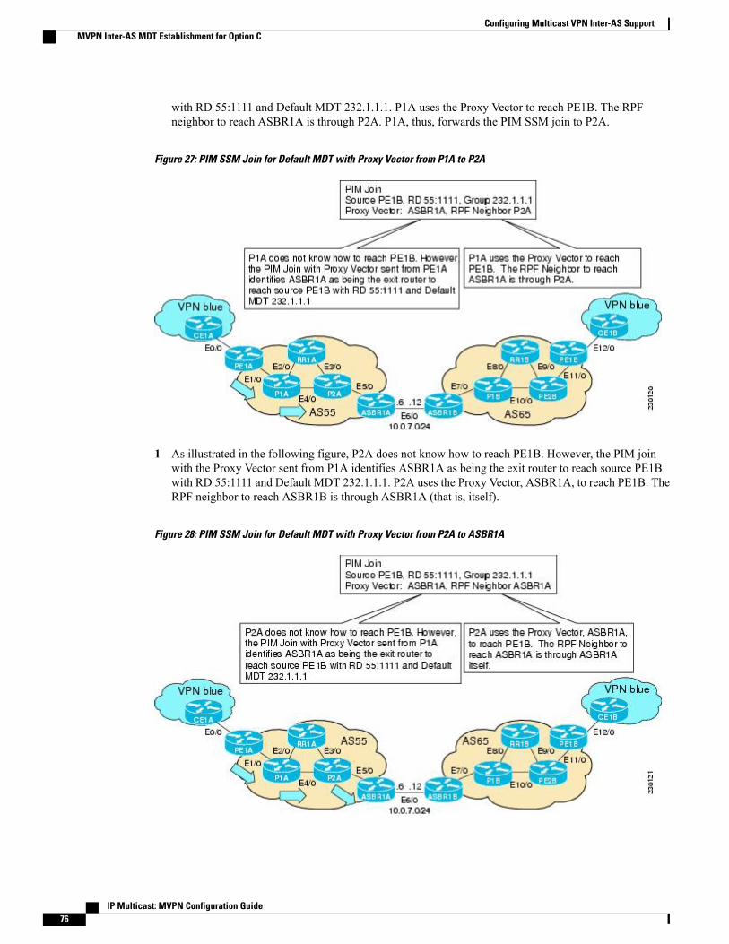
with RD 55:1111 and Default MDT 232.1.1.1. P1A uses the Proxy Vector to reach PE1B. The RPFneighbor to reach ASBR1A is through P2A. P1A, thus, forwards the PIM SSM join to P2A.
Figure 27: PIM SSM Join for Default MDT with Proxy Vector from P1A to P2A
1 As illustrated in the following figure, P2A does not know how to reach PE1B. However, the PIM joinwith the Proxy Vector sent from P1A identifies ASBR1A as being the exit router to reach source PE1Bwith RD 55:1111 and Default MDT 232.1.1.1. P2A uses the Proxy Vector, ASBR1A, to reach PE1B. TheRPF neighbor to reach ASBR1B is through ASBR1A (that is, itself).
Figure 28: PIM SSM Join for Default MDT with Proxy Vector from P2A to ASBR1A
IP Multicast: MVPN Configuration Guide76
Configuring Multicast VPN Inter-AS SupportMVPN Inter-AS MDT Establishment for Option C

1 As illustrated in the following figure, ASBR1A receives a PIM join with Proxy Vector from P2A. ASBR1Arealizes that the Proxy Vector is itself and sends a regular PIM join towards PE1B with an RPF neighborof ASBR1B. The PIM joins continue hop-by-hop building the SSM Default MDT until PE1B is finallyreached following standard PIM procedures.
Figure 29: PIM SSM Join for Default MDT with Proxy Vector from ASBR1A to PE1B
How to Configure Multicast VPN Inter-AS Support
Configuring the MDT Address Family in BGP for Multicast VPN Inter-AS SupportPerform this task to configure an MDT address family session on PE routers to to establish MDT peeringsessions for MVPN. Themdt keyword has been added to the address-family ipv4 command to configure anMDT address-family session.
Supported PolicyThe following policy configuration parameters are supported under the BGP MDT SAFI:
• Mandatory attributes and well-known attributes, such as the AS-path, multiexit discriminator (MED),BGP local preference, and next hop attributes.
• Standard communities, community lists, and route maps.
IP Multicast: MVPN Configuration Guide 77
Configuring Multicast VPN Inter-AS SupportHow to Configure Multicast VPN Inter-AS Support

Guidelines for Configuring MDT Address Family Sessions on PE Routers for MVPN Inter-ASSupport
When configuring routers for MVPN inter-AS support, follow these guidelines:
• For MVPN inter-AS Option A, BGP MDT address-family peering sessions are not required betweenthe PE routers because native IP forwarding is used by the PE routers. For option A, BGPMDT peeringsessions are only required for intra-AS VPN peering sessions.
• For MVPN inter-AS Option B, BGP MDT address-family peering sessions are only required betweenthe PEs and ASBRs. In the Option B inter-AS case where PE routers use iBGP to redistribute labeledVPNv4 routes to RRs of which ASBRs are clients, then BGP MDT address-family peering sessions arerequired between the PEs, ASBRs, and RRs.
• For MVPN inter-AS Option C, BGP MDT address-family peering sessions are only required betweenthe PEs and RRs.
Before You Begin
Before inter-AS VPN peering can be established through an MDT address family, MPLS and Cisco ExpressForwarding (CEF) must be configured in the BGP network and multiprotocol BGP on PE routers that provideVPN services to CE routers.
The following policy configuration parameters are not supported:Note
• Route-originator attribute
• NLRI prefix filtering (prefix lists, distribute lists)
• Extended community attributes (route target and site of origin)
>
SUMMARY STEPS
1. enable2. configure terminal3. router bgp as-number4. address-family ipv4 mdt5. neighbor neighbor-address activate6. end
DETAILED STEPS
PurposeCommand or Action
Enables privileged EXEC mode.enableStep 1
IP Multicast: MVPN Configuration Guide78
Configuring Multicast VPN Inter-AS SupportConfiguring the MDT Address Family in BGP for Multicast VPN Inter-AS Support

PurposeCommand or Action
Example:
Router> enable
• Enter your password if prompted.
Enters global configuration mode.configure terminal
Example:
Router# configure terminal
Step 2
Enters router configuration mode and creates a BGProuting process.
router bgp as-number
Example:
Router(config)# router bgp 65535
Step 3
Enters address family configuration mode to create an IPMDT address family session.
address-family ipv4 mdt
Example:
Router(config-router)# address-family ipv4 mdt
Step 4
Enables the MDT address family for this neighbor.neighbor neighbor-address activate
Example:
Router(config-router-af)# neighbor 192.168.1.1activate
Step 5
Exits address family configuration mode and entersprivileged EXEC mode.
end
Example:
Router(config-router-af)# end
Step 6
Displaying Information About IPv4 MDT Sessions in BGPPerform this optional task to display information about IPv4 MDT sessions in BGP.
SUMMARY STEPS
1. enable2. show ip bgp ipv4 mdt {all | rd | vrf vrf-name}
IP Multicast: MVPN Configuration Guide 79
Configuring Multicast VPN Inter-AS SupportDisplaying Information About IPv4 MDT Sessions in BGP

DETAILED STEPS
Step 1 enableUse this command to enable privileged EXEC mode.
• Enter your password if prompted.
Example:
Router> enable
Step 2 show ip bgp ipv4 mdt {all | rd | vrf vrf-name}Use this command to display IPv4 MDT sessions in the IPv4 BGP routing table.
The following is sample output from the show ip bgp ipv4 mdt command with the all keyword:
Example:
Router# show ip bgp ipv4 mdt all
BGP table version is 2, local router ID is 10.1.0.2Status codes: s suppressed, d damped, h history, * valid, > best, i - internal,
r RIB-failure, S StaleOrigin codes: i - IGP, e - EGP, ? - incomplete
Network Next Hop Metric LocPrf Weight PathRoute Distinguisher: 55:1111 (default for vrf blue)*> 10.5.5.5/32 10.1.0.1 55 0 23 24 25 54 ?* 10.9.9.9/32 0.0.0.0 0 ?
Clearing IPv4 MDT Peering Sessions in BGPPerform this optional task to reset IPv4 MDT address-family sessions using themdt keyword in one of thevarious forms of the clear ip bgpcommand. Due to the complexity of some of the keywords available for theclear ip bgp command, some of the keywords are documented as separate commands.
SUMMARY STEPS
1. enable2. Do one of the following:
• clear ip bgp ipv4 mdt as-number [in[prefix-filter]] [out] [soft [in[prefix-filter] | out]]
•• clear ip bgp ipv4 mdt peer-group peer-group-name [in [ prefix-filter]] [out] [soft [in[prefix-filter] | out]]
•• clear ip bgp ipv4 mdt update-group [index-group | neighbor-address]
IP Multicast: MVPN Configuration Guide80
Configuring Multicast VPN Inter-AS SupportClearing IPv4 MDT Peering Sessions in BGP

DETAILED STEPS
PurposeCommand or Action
Enables privileged EXEC mode.enableStep 1
Example:
Router> enable
• Enter your password if prompted.
(Optional) Resets IPv4 MDT address-family sessions.Do one of the following:Step 2
• clear ip bgp ipv4 mdt as-number[in[prefix-filter]] [out] [soft[in[prefix-filter] | out]]
• Specifying the clear ip bgp ipv4 mdt command with theas-numberargument resets IPv4 MDT address-family sessionsassociated with the specified autonomous system.
• The example for this form of the clear ip bgp ipv4 mdt commandshows how to initiate a hard reset for all IPv4 MDT address-familysessions in the autonomous system numbered 65700.
•• clear ip bgp ipv4 mdt peer-grouppeer-group-name [in [ prefix-filter]] [out][soft [ in[prefix-filter] | out]]
or•
• Specifying the clear ip bgp ipv4mdt commandwith the peer-groupkeyword resets IPv4 MDT address-family sessions for all membersof a BGP peer group.
• clear ip bgp ipv4 mdt update-group[index-group | neighbor-address]
Example:
Router# clear ip bgp ipv4 mdt 65700
• The example for this form of the clear ip bgp ipv4 mdt commandshows how to initiate a soft reset for inbound MDT address-familysessions with members of the peer group test. Outbound sessionsare unaffected.
Example: or
• Specifying the clear ip bgp ipv4 mdt command with theupdate-group keyword resets IPv4 MDT address-family sessionsfor all the members of a BGP update group.Example:
Router# clear ip bgp ipv4 mdt peer-grouptest soft in
• The example for this form of the clear ip bgp ipv4 mdt commandshows how to reset for all members of the update group 3.
Example:
Example:
Router# clear ip bgp ipv4 mdt update-group3
IP Multicast: MVPN Configuration Guide 81
Configuring Multicast VPN Inter-AS SupportClearing IPv4 MDT Peering Sessions in BGP

Configuring a PE Router to Send BGP MDT Updates to Build the Default MDTfor MVPN Inter-AS Support - Option B
Perform this task to configure PE routers in an Option B deployment to support the extensions necessary(BGP connector attribute, BGP MDT SAFI, and RPF Vector) to send BGP MDT updates to build the defaultMDT for MVPN inter-AS support.
SUMMARY STEPS
1. enable2. configure terminal3. router bgp as-number4. neighbor ip-address remote-as as-number5. address-family ipv4 mdt6. neighbor neighbor-address activate7. neighbor neighbor-address next-hop-self8. exit9. address-family vpnv410. neighbor neighbor-address activate11. neighbor neighbor-address send-community extended12. end
DETAILED STEPS
PurposeCommand or Action
Enables privileged EXEC mode.enableStep 1
Example:
Router> enable
• Enter your password if prompted.
Enters global configuration mode.configure terminal
Example:
Router# configure terminal
Step 2
Enters router configurationmode for the specified routingprocess.
router bgp as-number
Example:
Router(config)# router bgp 101
Step 3
IP Multicast: MVPN Configuration Guide82
Configuring Multicast VPN Inter-AS SupportConfiguring a PE Router to Send BGP MDT Updates to Build the Default MDT for MVPN Inter-AS Support - Option B

PurposeCommand or Action
Adds the IP address of the neighbor in the specifiedautonomous system to the IPv4 multiprotocol BGPneighbor table of the local router.
neighbor ip-address remote-as as-number
Example:
Router(config-router)# neighbor 192.168.1.1remote-as 45000
Step 4
Enters address family configuration mode to create anIPv4 MDT address family session.
address-family ipv4 mdt
Example:
Router(config-router)# address-family ipv4 mdt
Step 5
Enables the MDT address family for this neighbor.neighbor neighbor-address activate
Example:
Router(config-router-af)# neighbor 192.168.1.1activate
Step 6
Disables next hop processing of BGP updates on therouter.
neighbor neighbor-address next-hop-self
Example:
Router(config-router-af)# neighbor 192.168.1.1next-hop-self
Step 7
Exits address family configuration mode and returns torouter configuration mode.
exit
Example:
Router(config-router-af)# exit
Step 8
Enters address family configuration mode to create aVPNv4 address family session.
address-family vpnv4
Example:
Router(config-router)# address-family vpnv4
Step 9
Enables the VPNv4 address family for this neighbor.neighbor neighbor-address activate
Example:
Router(config-router-af)# neighbor 192.168.1.1activate
Step 10
Enables the standard and extended community attributesto be sent to this neighbor.
neighbor neighbor-address send-communityextended
Example:
Router(config-router-af)# neighbor 192.168.1.1send-community extended
Step 11
IP Multicast: MVPN Configuration Guide 83
Configuring Multicast VPN Inter-AS SupportConfiguring a PE Router to Send BGP MDT Updates to Build the Default MDT for MVPN Inter-AS Support - Option B

PurposeCommand or Action
Exits address family configuration mode and returns toprivileged EXEC mode.
end
Example:
Router(config-router-af)# end
Step 12
Configuring a PE Router to Send BGP MDT Updates to Build the Default MDTfor MVPN Inter-AS Support - Option C
Perform this task to configure PE routers in an Option B deployment to support the extensions necessary(BGP connector attribute, BGP MDT SAFI, and RPF Vector) to send BGP MDT updates to build the defaultMDT for MVPN inter-AS support.
SUMMARY STEPS
1. enable2. configure terminal3. router bgp as-number4. neighbor ip-address remote-as as-number5. address-family ipv4 mdt6. neighbor neighbor-address activate7. neighbor neighbor-address send-community extended8. exit9. address-family vpnv410. neighbor neighbor-address activate11. neighbor neighbor-address send-community extended12. end
DETAILED STEPS
PurposeCommand or Action
Enables privileged EXEC mode.enableStep 1
Example:
Router> enable
• Enter your password if prompted.
IP Multicast: MVPN Configuration Guide84
Configuring Multicast VPN Inter-AS SupportConfiguring a PE Router to Send BGP MDT Updates to Build the Default MDT for MVPN Inter-AS Support - Option C

PurposeCommand or Action
Enters global configuration mode.configure terminal
Example:
Router# configure terminal
Step 2
Enters router configurationmode for the specified routingprocess.
router bgp as-number
Example:
Router(config)# router bgp 101
Step 3
Adds the IP address of the neighbor in the specifiedautonomous system to the IPv4 multiprotocol BGPneighbor table of the local router.
neighbor ip-address remote-as as-number
Example:
Router(config-router)# neighbor 192.168.1.1remote-as 45000
Step 4
Enters address family configuration mode to create anIPv4 MDT address family session.
address-family ipv4 mdt
Example:
Router(config-router)# address-family ipv4 mdt
Step 5
Enables the MDT address family for this neighbor.neighbor neighbor-address activate
Example:
Router(config-router-af)# neighbor 192.168.1.1activate
Step 6
Enables the standard and extended community attributesto be sent to this neighbor.
neighbor neighbor-address send-communityextended
Example:
Router(config-router-af)# neighbor 192.168.1.1send-community extended
Step 7
Exits address family configuration mode and returns torouter configuration mode.
exit
Example:
Router(config-router-af)# exit
Step 8
Enters address family configuration mode to create aVPNv4 address family session.
address-family vpnv4
Example:
Router(config-router)# address-family vpnv4
Step 9
IP Multicast: MVPN Configuration Guide 85
Configuring Multicast VPN Inter-AS SupportConfiguring a PE Router to Send BGP MDT Updates to Build the Default MDT for MVPN Inter-AS Support - Option C

PurposeCommand or Action
Enables the VPNv4 address family for this neighbor.neighbor neighbor-address activate
Example:
Router(config-router-af)# neighbor 192.168.1.1activate
Step 10
Enables the standard and extended community attributesto be sent to this neighbor.
neighbor neighbor-address send-communityextended
Example:
Router(config-router-af)# neighbor 192.168.1.1send-community extended
Step 11
Exits address family configuration mode and returns toprivileged EXEC mode.
end
Example:
Router(config-router-af)# end
Step 12
Verifying the Establishment of Inter-AS MDTs in Option B and Option CDeployments
Perform this optional task to verify the establishment of Inter-AS MDTs in Option B and Option C MVPNinter-AS deployments.
The steps in this optional task can be performed in any order. All steps in this task are optional.Note
SUMMARY STEPS
1. enable2. show ip mroute proxy3. show ip pim [vrf vrf-name] neighbor [interface-type interface-number]4. show ip rpf [vrf vrf-name] {route-distinguisher | source-address [group-address] [rd route-distinguisher]}
[metric]5. show ip pim [vrf vrf-name] mdt bgp
DETAILED STEPS
Step 1 enable
IP Multicast: MVPN Configuration Guide86
Configuring Multicast VPN Inter-AS SupportVerifying the Establishment of Inter-AS MDTs in Option B and Option C Deployments

Use this command to enable privileged EXEC mode.
• Enter your password if prompted.
Example:
Router> enable
Step 2 show ip mroute proxyUse this command to display information about RPF Vectors received on a multicast router.
• The information displayed in the output of this command can be used to determine if an RPF Vector proxy isreceived on a core router.
The following is sample output from the show ip mroute proxy command:
Example:
Router# show ip mroute proxy
(192.168.0.8, 232.1.1.1)Proxy Assigner Origin Uptime/Expire55:1111/192.168.0.4 10.0.3.1 PIM 00:03:29/00:02:0655:1111/192.168.0.4 10.0.3.2 PIM 00:17:47/00:02:06
Step 3 show ip pim [vrf vrf-name] neighbor [interface-type interface-number]Use this command to display the PIM neighbors discovered by PIMv1 router query messages or PIMv2 hello messages.
The P flag indicates that the neighbor has announced (through PIM hello messages) its capability to handle RPF Vectorsin PIM join messages. All software versions that support the PIM RPF Vector feature announce this PIM hello option.An RPF Vector is only included in PIM messages when all PIM neighbors on an RPF interface support it.
The following is sample output from the show ip pim neighbor command:
Example:
Router# show ip pim neighborPIM Neighbor TableMode: B - Bidir Capable, DR - Designated Router, N - Default DR Priority,
S - State Refresh CapableNeighbor Interface Uptime/Expires Ver DRAddress Prio/Mode10.0.0.1 GigabitEthernet10/2 00:01:29/00:01:15 v2 1 / S10.0.0.3 GigabitEthernet10/3 00:01:15/00:01:28 v2 1 / DR S P
Step 4 show ip rpf [vrf vrf-name] {route-distinguisher | source-address [group-address] [rd route-distinguisher]} [metric]Use this command to display information about how IP multicast routing does RPF.
The following is sample output from the show ip rpfcommand:
Example:
Router# show ip rpf 10.7.0.7 232.1.1.1 rd 55:1111
RPF information for ? (10.7.0.7)RPF interface: GigabitEthernet2/2RPF neighbor: ? (10.0.1.3)RPF route/mask: 10.5.0.5/32
IP Multicast: MVPN Configuration Guide 87
Configuring Multicast VPN Inter-AS SupportVerifying the Establishment of Inter-AS MDTs in Option B and Option C Deployments

RPF type: unicast (UNKNOWN)RPF recursion count: 0Doing distance-preferred lookups across tablesBGP lookup of 55:1111/10.7.0.7 next_hop: 10.5.0.5PROXY vector: 10.5.0.5
Step 5 show ip pim [vrf vrf-name] mdt bgpUse this command to display information about the BGP advertisement of RDs for the MDT default group.
The following is sample output from the show ip pim mdt bgp command:
Example:
Router# show ip pim mdt bgpMDT (Route Distinguisher + IPv4) Router ID Next HopMDT group 232.1.1.155:1111:192.168.0.2 192.168.0.2 192.168.0.255:1111:192.168.0.8 192.168.0.4 192.168.0.4
Configuration Examples for Multicast VPN Inter-AS Support
Configuring an IPv4 MDT Address-Family Session for Multicast VPN Inter-ASSupport Example
The following examples shows how to configure a router to support an IPv4 MDT address-family sessionwith the BGP neighbor at 10.1.1.2:
router bgp 1address-family ipv4 mdtneighbor 10.1.1.2 activate
Configuring a PE Router to Send BGP MDT Updates to Build the Default MDTfor MVPN Inter-AS Support
The following example shows how to configure a PE router to support the extensions necessary (BGP connectorattribute, BGPMDT SAFI, and RPF Vector) to send BGPMDT updates to build the default MDT for MVPNinter-AS support in an Option B deployment. Only the relevant configuration is shown in this example.
!ip multicast-routingip multicast-routing vrf blueip multicast vrf blue rpf proxy rd vector!...router bgp 55...
IP Multicast: MVPN Configuration Guide88
Configuring Multicast VPN Inter-AS SupportConfiguration Examples for Multicast VPN Inter-AS Support

!address-family ipv4 mdtneighbor 192.168.0.2 activateneighbor 192.168.0.2 next-hop-selfneighbor 192.168.0.4 activateneighbor 192.168.0.4 next-hop-selfexit-address-family!address-family vpnv4neighbor 192.168.0.2 activateneighbor 192.168.0.2 send-community extendedneighbor 192.168.0.4 activateneighbor 192.168.0.4 send-community extendedexit-address-family!...!ip pim ssm default!
Configuring a PE Router to Send BGP MDT Updates to Build the Default MDTfor MVPN Inter-AS Support
The following example shows how to configure a PE router to support the extensions necessary (BGP connectorattribute, BGPMDT SAFI, and RPF Vector) to send BGPMDT updates to build the default MDT for MVPNinter-AS support in an Option B deployment. Only the relevant configuration is shown in this example.
!ip multicast-routingip multicast-routing vrf blueip multicast rpf proxy vector!...!router bgp 65...!address-family ipv4neighbor 10.252.252.10 activateneighbor 10.252.252.10 send-labelno auto-summaryno synchronizationexit-address-family!address-family ipv4 mdtneighbor 10.252.252.10 activateneighbor 10.252.252.10 send-community extendedexit-address-family!address-family vpnv4neighbor 10.252.252.10 activateneighbor 10.252.252.10 send-community extendedexit-address-family!...!ip pim ssm default!
IP Multicast: MVPN Configuration Guide 89
Configuring Multicast VPN Inter-AS SupportConfiguring a PE Router to Send BGP MDT Updates to Build the Default MDT for MVPN Inter-AS Support

Configuring Back-to-Back ASBR PEs - Option A ExampleThe following example shows how to configure support for MVPN inter-AS support Option A. Thisconfiguration example is based on the sample inter-AS network Option A topology illustrated in the figure.
In this configuration example, PE3A in AS1 is attached directly to PE3B in AS2. The two PE routers areattached by physical interfaces, one physical interface for each of the VPNs (VPN blue and VPN green) whoseroutes need to be passed from AS1 to AS2, and vice versa. Each PE will treat the other as if it were a CErouter; that is, the PEs associate each interface with a VRF and use eBGP to distribute unlabeled IPv4 addressesto each other. Intermediate System-to-Intermediate System (IS-IS) is being used for the BGP peerings in bothautonomous systems, and Routing Information Protocol (RIP) is being used on the PE routers that face theCE routers to dynamically learn the routes from the VRFs and advertise them as VPNv4 routes to the remotePE routers. RIP is also being used between the ASBRs to set up the eBGP peerings between PE3A and PE3B.
For Option A, any IGP can be used to exchange the IPv4 routes for the loopback interfaces.Note
Figure 30: Topology for MVPN Inter-AS Support Option A Configuration Example
The table provides information about the topology used for the Option A configuration example presented inthis section.
Table 3: Topology Information for MVPN Inter-AS Option A Configuration Example
Default MDT(PIM-SSM)
Loopback0Interface
AS NumberRDVPNPE Router
232.1.1.110.1.1.1/32155:1111greenPE1A
232.1.1.110.1.1.2/32155:1111bluePE2A
IP Multicast: MVPN Configuration Guide90
Configuring Multicast VPN Inter-AS SupportConfiguring Back-to-Back ASBR PEs - Option A Example

Default MDT(PIM-SSM)
Loopback0Interface
AS NumberRDVPNPE Router
232.1.1.110.1.1.3/32155:1111blue/greenPE3A
232.2.2.210.2.2.1/32255:2222greenPE1B
232.2.2.210.2.2.2/32255:2222bluePE2B
232.2.2.210.2.2.3/32255:2222blue/greenPE3B
PE1A
!version 12.0service timestamps debug uptimeservice timestamps log uptimeno service password-encryption!hostname PE1A!boot-start-markerboot-end-marker!!ip subnet-zeroip cefno ip domain-lookupip vrf greenrd 55:2222route-target export 55:2222route-target import 55:2222mdt default 232.2.2.2!ip multicast-routingip multicast-routing vrf greenmpls label protocol ldp!!!interface Loopback0ip address 10.1.1.1 255.255.255.255no ip directed-broadcastip router isisip pim sparse-mode!interface GigabitEthernet0/0ip vrf forwarding greenip address 172.25.11.1 255.255.255.0no ip directed-broadcastip pim sparse-modetag-switching ip!interface GigabitEthernet1/0ip address 172.30.41.1 255.255.255.0no ip directed-broadcastip router isisip pim sparse-modetag-switching ip!router isisnet 49.0000.0000.1111.00!router rip
IP Multicast: MVPN Configuration Guide 91
Configuring Multicast VPN Inter-AS SupportConfiguring Back-to-Back ASBR PEs - Option A Example

version 2!address-family ipv4 vrf greenversion 2network 172.25.0.0no auto-summaryexit-address-family!router bgp 1no synchronizationbgp log-neighbor-changesneighbor 10.1.1.2 remote-as 1neighbor 10.1.1.2 update-source Loopback0neighbor 10.1.1.3 remote-as 1neighbor 10.1.1.3 update-source Loopback0no auto-summary!address-family ipv4 mdtneighbor 10.1.1.2 activateneighbor 10.1.1.3 activateexit-address-family!address-family vpnv4neighbor 10.1.1.2 activateneighbor 10.1.1.2 send-community extendedneighbor 10.1.1.3 activateneighbor 10.1.1.3 send-community extendedexit-address-family!address-family ipv4 vrf greenredistribute rip metric 1no synchronizationexit-address-family!ip classless!ip pim ssm defaultip pim vrf green send-rp-announce GigabitEthernet0/0 scope 32ip pim vrf green send-rp-discovery 0/0 scope 32ip pim vrf green register-rate-limit 2!!!control-plane!!line con 0line aux 0line vty 0 4login!no cns aaa enableend
PE2A
!version 12.0service timestamps debug uptimeservice timestamps log uptimeno service password-encryption!hostname PE2A!boot-start-markerboot-end-marker!!ip subnet-zeroip cefno ip domain-lookup
IP Multicast: MVPN Configuration Guide92
Configuring Multicast VPN Inter-AS SupportConfiguring Back-to-Back ASBR PEs - Option A Example

ip vrf bluerd 55:1111route-target export 55:1111route-target import 55:1111mdt default 232.1.1.1!ip multicast-routingip multicast-routing vrf bluempls label protocol ldp!!!interface Loopback0ip address 10.1.1.2 255.255.255.255no ip directed-broadcastip router isisip pim sparse-mode!interface GigabitEthernet0/0ip vrf forwarding blueip address 172.17.12.2 255.255.255.0no ip directed-broadcastip pim sparse-modetag-switching ip!interface GigabitEthernet1/0no ip addressno ip directed-broadcastshutdown!interface GigabitEthernet2/0ip address 172.19.142.2 255.255.255.0no ip directed-broadcastip router isisip pim sparse-modetag-switching ip!router isisnet 49.0000.0000.2222.00!router ripversion 2!address-family ipv4 vrf blueversion 2network 172.17.0.0no auto-summaryexit-address-family!router bgp 1no synchronizationbgp log-neighbor-changesneighbor 10.1.1.1 remote-as 1neighbor 10.1.1.1 update-source Loopback0neighbor 10.1.1.3 remote-as 1neighbor 10.1.1.3 update-source Loopback0no auto-summary!address-family ipv4 mdtneighbor 10.1.1.1 activateneighbor 10.1.1.3 activateexit-address-family!address-family vpnv4neighbor 10.1.1.1 activateneighbor 10.1.1.1 send-community extendedneighbor 10.1.1.3 activateneighbor 10.1.1.3 send-community extendedexit-address-family!address-family ipv4 vrf blueredistribute rip metric 1no synchronization
IP Multicast: MVPN Configuration Guide 93
Configuring Multicast VPN Inter-AS SupportConfiguring Back-to-Back ASBR PEs - Option A Example

exit-address-family!ip classless!ip pim ssm defaultip pim vrf blue send-rp-announce GigabitEthernet0/0 scope 32ip pim vrf blue send-rp-discovery GigabitEthernet0/0 scope 32ip pim vrf blue ssm default!!!control-plane!!line con 0line aux 0line vty 0 4login!no cns aaa enableend
PE3A
!version 12.0service timestamps debug uptimeservice timestamps log uptimeno service password-encryption!hostname PE3A!boot-start-markerboot-end-marker!!ip subnet-zeroip cefno ip domain-lookupip vrf bluerd 55:1111route-target export 55:1111route-target import 55:1111mdt default 232.1.1.1!ip vrf greenrd 55:2222route-target export 55:2222route-target import 55:2222mdt default 232.2.2.2!ip multicast-routingip multicast-routing vrf blueip multicast-routing vrf greenmpls label protocol ldp!!!interface Loopback0ip address 10.1.1.3 255.255.255.255no ip directed-broadcastip router isisip pim sparse-mode!interface GigabitEthernet0/0no ip addressno ip directed-broadcastshutdown!interface GigabitEthernet1/0no ip address
IP Multicast: MVPN Configuration Guide94
Configuring Multicast VPN Inter-AS SupportConfiguring Back-to-Back ASBR PEs - Option A Example

no ip directed-broadcastshutdown!interface GigabitEthernet2/0no ip addressno ip directed-broadcastshutdown!interface GigabitEthernet3/0ip address 192.168.143.3 255.255.255.0no ip directed-broadcastip router isisip pim sparse-modetag-switching ip!interface GigabitEthernet4/0ip vrf forwarding blueip address 172.20.34.3 255.255.255.0no ip directed-broadcastip pim sparse-dense-modetag-switching ip!interface GigabitEthernet5/0ip vrf forwarding greenip address 172.23.35.3 255.255.255.0no ip directed-broadcastip pim sparse-dense-modetag-switching ip!router eigrp 1!address-family ipv4 vrf bluenetwork 172.20.0.0no auto-summaryexit-address-family!router isisnet 49.0000.0000.3333.00!router ripversion 2!address-family ipv4 vrf greenversion 2redistribute bgp 1 metric 2network 172.23.0.0no auto-summaryexit-address-family!address-family ipv4 vrf blueversion 2redistribute bgp 1 metric 1network 172.20.0.0no auto-summaryexit-address-family!router bgp 1no synchronizationbgp log-neighbor-changesneighbor 10.1.1.1 remote-as 1neighbor 10.1.1.1 update-source Loopback0neighbor 10.1.1.2 remote-as 1neighbor 10.1.1.2 update-source Loopback0no auto-summary!address-family ipv4 mdtneighbor 10.1.1.1 activateneighbor 10.1.1.2 activateexit-address-family!address-family vpnv4neighbor 10.1.1.1 activateneighbor 10.1.1.1 send-community extended
IP Multicast: MVPN Configuration Guide 95
Configuring Multicast VPN Inter-AS SupportConfiguring Back-to-Back ASBR PEs - Option A Example

neighbor 10.1.1.2 activateneighbor 10.1.1.2 send-community extendedbgp redistribute-internalexit-address-family!address-family ipv4 vrf greenno synchronizationbgp redistribute-internalexit-address-family!address-family ipv4 vrf blueredistribute ripno synchronizationbgp redistribute-internalexit-address-family!ip classless!ip pim ssm defaultip pim vrf blue ssm default!!!control-plane!!line con 0line aux 0line vty 0 4login!no cns aaa enableend
PE3B
!version 12.0service timestamps debug uptimeservice timestamps log uptimeno service password-encryption!hostname PE3B!boot-start-markerboot-end-marker!!ip subnet-zeroip cefno ip domain-lookupip vrf bluerd 55:1111route-target export 55:1111route-target import 55:1111mdt default 232.1.1.1!ip vrf greenrd 55:2222route-target export 55:2222route-target import 55:2222mdt default 232.2.2.2!ip multicast-routingip multicast-routing vrf blueip multicast-routing vrf greenmpls label protocol ldp!!!interface Loopback0
IP Multicast: MVPN Configuration Guide96
Configuring Multicast VPN Inter-AS SupportConfiguring Back-to-Back ASBR PEs - Option A Example

ip address 10.2.2.3 255.255.255.255no ip directed-broadcastip router isisip pim sparse-mode!interface GigabitEthernet0/0no ip addressno ip directed-broadcastshutdown!interface GigabitEthernet1/0no ip addressno ip directed-broadcastshutdown!interface GigabitEthernet2/0no ip addressno ip directed-broadcastshutdown!interface GigabitEthernet3/0ip address 172.16.43.3 255.255.255.0no ip directed-broadcastip router isisip pim sparse-modetag-switching ip!interface GigabitEthernet4/0ip vrf forwarding blueip address 172.20.34.4 255.255.255.0no ip directed-broadcastip pim sparse-dense-modetag-switching ip!interface GigabitEthernet5/0ip vrf forwarding greenip address 172.23.35.4 255.255.255.0no ip directed-broadcastip pim sparse-dense-modetag-switching ip!router isisnet 49.0000.0000.3333.00!router ripversion 2!address-family ipv4 vrf greenversion 2network 172.23.0.0no auto-summaryexit-address-family!address-family ipv4 vrf blueversion 2network 172.20.0.0no auto-summaryexit-address-family!router bgp 2no synchronizationbgp log-neighbor-changesredistribute rip metric 1neighbor 10.2.2.1 remote-as 2neighbor 10.2.2.1 update-source Loopback0neighbor 10.2.2.2 remote-as 2neighbor 10.2.2.2 update-source Loopback0no auto-summary!address-family ipv4 mdtneighbor 10.2.2.1 activateneighbor 10.2.2.2 activateexit-address-family
IP Multicast: MVPN Configuration Guide 97
Configuring Multicast VPN Inter-AS SupportConfiguring Back-to-Back ASBR PEs - Option A Example

!address-family vpnv4neighbor 10.2.2.1 activateneighbor 10.2.2.1 send-community extendedneighbor 10.2.2.2 activateneighbor 10.2.2.2 send-community extendedexit-address-family!address-family ipv4 vrf greenredistribute ripno synchronizationexit-address-family!address-family ipv4 vrf blueredistribute ripno synchronizationexit-address-family!ip classless!ip pim ssm defaultip pim vrf blue ssm default!!!control-plane!!line con 0line aux 0line vty 0 4login!no cns aaa enableend
PE2B
!version 12.0service timestamps debug uptimeservice timestamps log uptimeno service password-encryption!hostname PE2B!boot-start-markerboot-end-marker!!ip subnet-zeroip cefno ip domain-lookupip vrf bluerd 55:1111route-target export 55:1111route-target import 55:1111mdt default 232.1.1.1!ip multicast-routingip multicast-routing vrf bluempls label protocol ldp!!!interface Loopback0ip address 10.2.2.2 255.255.255.255no ip directed-broadcastip router isisip pim sparse-mode!
IP Multicast: MVPN Configuration Guide98
Configuring Multicast VPN Inter-AS SupportConfiguring Back-to-Back ASBR PEs - Option A Example

interface GigabitEthernet0/0ip vrf forwarding blueip address 172.18.22.2 255.255.255.0no ip directed-broadcastip pim sparse-modetag-switching ip!interface GigabitEthernet1/0no ip addressno ip directed-broadcastshutdown!interface GigabitEthernet2/0ip address 172.19.42.2 255.255.255.0no ip directed-broadcastip router isisip pim sparse-modetag-switching ip!router isisnet 49.0000.0000.2222.00!router rip!address-family ipv4 vrf bluenetwork 172.18.0.0no auto-summaryexit-address-family!router bgp 2no synchronizationbgp log-neighbor-changesneighbor 10.2.2.1 remote-as 2neighbor 10.2.2.1 update-source Loopback0neighbor 10.2.2.3 remote-as 2neighbor 10.2.2.3 update-source Loopback0no auto-summary!address-family ipv4 mdtneighbor 10.2.2.1 activateneighbor 10.2.2.3 activateexit-address-family!address-family vpnv4neighbor 10.2.2.1 activateneighbor 10.2.2.1 send-community extendedneighbor 10.2.2.3 activateneighbor 10.2.2.3 send-community extendedexit-address-family!address-family ipv4 vrf blueno synchronizationexit-address-family!ip classless!ip pim ssm defaultip pim vrf blue ssm default!!!control-plane!!line con 0line aux 0line vty 0 4login!no cns aaa enableend
IP Multicast: MVPN Configuration Guide 99
Configuring Multicast VPN Inter-AS SupportConfiguring Back-to-Back ASBR PEs - Option A Example

PE1B
!version 12.0service timestamps debug uptimeservice timestamps log uptimeno service password-encryption!hostname PE1B!boot-start-markerboot-end-marker!!ip subnet-zeroip cefno ip domain-lookupip vrf greenrd 55:2222route-target export 55:2222route-target import 55:2222mdt default 232.2.2.2!ip multicast-routingip multicast-routing vrf greenmpls label protocol ldp!!!interface Loopback0ip address 10.2.2.1 255.255.255.255no ip directed-broadcastip router isisip pim sparse-mode!interface GigabitEthernet0/0ip vrf forwarding greenip address 172.25.111.1 255.255.255.0no ip directed-broadcastip pim sparse-modetag-switching ip!interface GigabitEthernet1/0ip address 172.30.141.1 255.255.255.0no ip directed-broadcastip router isisip pim sparse-modetag-switching ip!router isisnet 49.0000.0000.1111.00!router ripversion 2!address-family ipv4 vrf greenversion 2network 172.25.0.0no auto-summaryexit-address-family!router bgp 2no synchronizationbgp log-neighbor-changesneighbor 10.2.2.2 remote-as 2neighbor 10.2.2.2 update-source Loopback0neighbor 10.2.2.3 remote-as 2neighbor 10.2.2.3 update-source Loopback0no auto-summary!address-family ipv4 mdtneighbor 10.2.2.2 activate
IP Multicast: MVPN Configuration Guide100
Configuring Multicast VPN Inter-AS SupportConfiguring Back-to-Back ASBR PEs - Option A Example

neighbor 10.2.2.3 activateexit-address-family!address-family vpnv4neighbor 10.2.2.2 activateneighbor 10.2.2.2 send-community extendedneighbor 10.2.2.3 activateneighbor 10.2.2.3 send-community extendedexit-address-family!address-family ipv4 vrf greenno synchronizationexit-address-family!ip classless!ip pim ssm default!!!control-plane!!line con 0line aux 0line vty 0 4login!no cns aaa enableend
Configuring the Exchange of VPNv4 Routes Directly Between ASBRs - OptionB Example
The following example shows how to configure MVPN inter-AS support in an Option B deployment. Thisconfiguration is based on the sample inter-AS topology illustrated in the figure.
In this configuration example, PE1A and PE2A are configured to use iBGP to redistribute labeled VPNv4routes to each other and to ASBR1A, and PE1B is configured to redistribute labeled VPNv4 routes to ASBR1B.ASBR1A and ASBR1B are configured to use eBGP to exchange those labeled VPNv4 routes to each other.
Figure 31: Topology for MVPN Inter-AS Support Option B Configuration Example
IP Multicast: MVPN Configuration Guide 101
Configuring Multicast VPN Inter-AS SupportConfiguring the Exchange of VPNv4 Routes Directly Between ASBRs - Option B Example

The table provides information about the topology used for this particular Option B configuration example.
Table 4: Topology Information for MVPN Inter-AS Support Option B Configuration Example
Default MDT (PIM-SSM)Loopback0 InterfacesAS NumberPE or ASBR Router
232.1.1.1192.168.0.1/3255PE1A
232.1.1.1192.168.0.2/3255PE2A
232.1.1.1192.168.0.4/3255ASBR1A
232.1.1.1192.168.0.9/3265ASBR1B
232.1.1.1192.168.0.8/3265PE1B
PE1A
!ip vrf bluerd 55:1111mdt default 232.1.1.1!ip multicast-routingip multicast-routing vrf blueip multicast vrf blue rpf proxy rd vector!...!interface GigabitEthernet0/0ip vrf forwarding blueip pim sparse-mode!...!router bgp 55no synchronizationbgp log-neighbor-changesneighbor 192.168.0.2 remote-as 55neighbor 192.168.0.2 update-source Loopback0neighbor 192.168.0.4 remote-as 55neighbor 192.168.0.4 update-source Loopback0no auto-summary!address-family ipv4 mdtneighbor 192.168.0.2 activateneighbor 192.168.0.2 next-hop-selfneighbor 192.168.0.4 activateneighbor 192.168.0.4 next-hop-selfexit-address-family!address-family vpnv4neighbor 192.168.0.2 activateneighbor 192.168.0.2 send-community extendedneighbor 192.168.0.4 activateneighbor 192.168.0.4 send-community extendedexit-address-family!address-family ipv4 vrf blue
IP Multicast: MVPN Configuration Guide102
Configuring Multicast VPN Inter-AS SupportConfiguring the Exchange of VPNv4 Routes Directly Between ASBRs - Option B Example
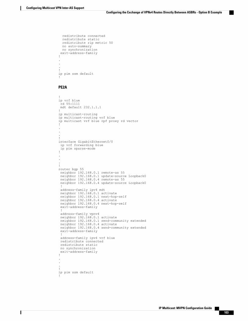
redistribute connectedredistribute staticredistribute rip metric 50no auto-summaryno synchronizationexit-address-family!...!ip pim ssm default!
PE2A
!ip vrf bluerd 55:1111mdt default 232.1.1.1!ip multicast-routingip multicast-routing vrf blueip multicast vrf blue rpf proxy rd vector!...!interface GigabitEthernet0/0ip vrf forwarding blueip pim sparse-mode!...!router bgp 55neighbor 192.168.0.1 remote-as 55neighbor 192.168.0.1 update-source Loopback0neighbor 192.168.0.4 remote-as 55neighbor 192.168.0.4 update-source Loopback0!address-family ipv4 mdtneighbor 192.168.0.1 activateneighbor 192.168.0.1 next-hop-selfneighbor 192.168.0.4 activateneighbor 192.168.0.4 next-hop-selfexit-address-family!address-family vpnv4neighbor 192.168.0.1 activateneighbor 192.168.0.1 send-community extendedneighbor 192.168.0.4 activateneighbor 192.168.0.4 send-community extendedexit-address-family!address-family ipv4 vrf blueredistribute connectedredistribute staticno synchronizationexit-address-family!...!ip pim ssm default!
IP Multicast: MVPN Configuration Guide 103
Configuring Multicast VPN Inter-AS SupportConfiguring the Exchange of VPNv4 Routes Directly Between ASBRs - Option B Example

ASBR1A
!ip multicast-routingip multicast-routing vrf blue!...!!interface GigabitEthernet0/0ip pim sparse-mode!...!router bgp 55bgp log-neighbor-changesneighbor 10.0.5.9 remote-as 65neighbor 192.168.0.1 remote-as 55neighbor 192.168.0.1 update-source Loopback0neighbor 192.168.0.2 remote-as 55neighbor 192.168.0.2 update-source Loopback0!address-family ipv4 mdtneighbor 10.0.5.9 activateneighbor 192.168.0.1 activateneighbor 192.168.0.1 next-hop-selfneighbor 192.168.0.2 activateneighbor 192.168.0.2 next-hop-selfexit-address-family!address-family vpnv4neighbor 10.0.5.9 activateneighbor 10.0.5.9 send-community extendedneighbor 192.168.0.1 activateneighbor 192.168.0.1 send-community extendedneighbor 192.168.0.1 next-hop-selfneighbor 192.168.0.2 activateneighbor 192.168.0.2 send-community extendedneighbor 192.168.0.2 next-hop-selfexit-address-family!...!ip pim ssm default!
ASBR1B
!ip multicast-routingip multicast-routing vrf blue!...!interface GigabitEthernet0/0ip pim sparse-mode!...!router bgp 65
IP Multicast: MVPN Configuration Guide104
Configuring Multicast VPN Inter-AS SupportConfiguring the Exchange of VPNv4 Routes Directly Between ASBRs - Option B Example

bgp log-neighbor-changesneighbor 10.0.5.4 remote-as 55neighbor 192.168.0.8 remote-as 65neighbor 192.168.0.8 update-source Loopback0!address-family ipv4 mdtneighbor 10.0.5.4 activateneighbor 192.168.0.8 activateneighbor 192.168.0.8 next-hop-selfexit-address-family!address-family vpnv4neighbor 10.0.5.4 activateneighbor 10.0.5.4 send-community extendedneighbor 192.168.0.8 activateneighbor 192.168.0.8 send-community extendedneighbor 192.168.0.8 next-hop-selfexit-address-family!...!ip pim ssm default!
PE1B
!ip vrf bluerd 55:1111mdt default 232.1.1.1!ip multicast-routingip multicast-routing vrf blueip multicast vrf blue rpf proxy rd vector!...!interface GigabitEthernet0/0ip vrf forwarding blueip pim sparse-mode!...!router bgp 65neighbor 192.168.0.9 remote-as 65neighbor 192.168.0.9 update-source Loopback0!address-family ipv4 mdtneighbor 192.168.0.9 activateneighbor 192.168.0.9 next-hop-selfexit-address-family!address-family vpnv4neighbor 192.168.0.9 activateneighbor 192.168.0.9 send-community extendedexit-address-family!address-family ipv4 vrf blueredistribute connectedredistribute staticredistribute rip metric 50no synchronizationexit-address-family!.
IP Multicast: MVPN Configuration Guide 105
Configuring Multicast VPN Inter-AS SupportConfiguring the Exchange of VPNv4 Routes Directly Between ASBRs - Option B Example

.
.!ip pim ssm default!The following is sample output from the show ip pim mdt bgp command for PE1A, PE2A, and PE1B. Thesample output displays information about the BGP advertisement of RDs for theMDT default group 232.1.1.1.The output displays the MDT default groups advertised, the RDs and source addresses of sources sending totheMDT default groups, the BGP router ID of the advertising routers, and the BGP next hop address containedin the advertisements.
PE1A# show ip pim mdt bgpMDT (Route Distinguisher + IPv4) Router ID Next HopMDT group 232.1.1.155:1111:192.168.0.2 192.168.0.2 192.168.0.255:1111:192.168.0.8 192.168.0.4 192.168.0.4
PE2A# show ip pim mdt bgpMDT (Route Distinguisher + IPv4) Router ID Next HopMDT group 232.1.1.155:1111:192.168.0.1 192.168.0.1 192.168.0.155:1111:192.168.0.8 192.168.0.4 192.168.0.4
PE1B# show ip pim mdt bgpMDT (Route Distinguisher + IPv4) Router ID Next HopMDT group 232.1.1.155:1111:192.168.0.1 192.168.0.9 192.168.0.955:1111:192.168.0.2 192.168.0.9 192.168.0.9
The following are sample outputs from the show ip mroute proxy command for PE1A, PE2A, and PE1B.The output displays information about the RPFVectors learned by each PE router in this configuration example.The RPFVector is the exit address of the ASBR router through which PIMmessages are sent to reach inter-ASsources. The “Proxy” field displays the RPF Vectors learned by the PE routers. Each RPF Vector listed underthe “Proxy” field is prepended by the RD associated with the RPF Vector. Because the PE routers are theassigners of the RPF Vector (that is, the PE routers insert the RPF Vector into PIM joins), 0.0.0.0 is the addressdisplayed under the “Assigner” field in all the sample outputs. Finally, because PE routers learn the RPF Vectorfrom BGPMDT SAFI updates, BGPMDT is displayed as the origin under the “Origin” field in all the outputs.
PE1A# show ip mroute proxy(192.168.0.8, 232.1.1.1)Proxy Assigner Origin Uptime/Expire55:1111/192.168.0.4 0.0.0.0 BGP MDT 00:13:07/stopped
PE2A# show ip mroute proxy(192.168.0.8, 232.1.1.1)Proxy Assigner Origin Uptime/Expire55:1111/192.168.0.4 0.0.0.0 BGP MDT 00:14:28/stopped
PE1B# show ip mroute proxy(192.168.0.1, 232.1.1.1)Proxy Assigner Origin Uptime/Expire55:1111/192.168.0.9 0.0.0.0 BGP MDT 00:35:19/stopped
(192.168.0.2, 232.1.1.1)Proxy Assigner Origin Uptime/Expire55:1111/192.168.0.9 0.0.0.0 BGP MDT 00:35:49/stopped
The following is sample output from the show ip mroute proxy command from P1A. Because P routers learnthe RPF Vector from the PIM joins sent from PE routers, the IP addresses of PE1A (10.0.3.1) and PE2A(10.0.3.2) are displayed under the “Assigner” field in the output for P1A. Because P1A learns the RPF Vectorfrom encodings in the PIM join message, PIM is displayed as the origin under the “Origin” field.
P1A# show ip mroute proxy
(192.168.0.8, 232.1.1.1)Proxy Assigner Origin Uptime/Expire55:1111/192.168.0.4 10.0.3.1 PIM 00:03:29/00:02:0655:1111/192.168.0.4 10.0.3.2 PIM 00:17:47/00:02:06
The following is sample output from the show ip mroute proxy command for ASBR1A and ASBR1B. If arouter receives an RPF Vector that references a local interface (which occurs in an Option B deployment when
IP Multicast: MVPN Configuration Guide106
Configuring Multicast VPN Inter-AS SupportConfiguring the Exchange of VPNv4 Routes Directly Between ASBRs - Option B Example

an ASBR receives a RPF Vector owned by a local interface), the router discards the RPF Vector and performsa normal RPF lookup using information that the router learned from BGP MDT SAFI updates. In the outputfor all ASBR routers, under the “Proxy” field, the word “local” is displayed instead of the RPF Vector becauseASBR1A and ASBR1B are using local interfaces to perform RPF lookups for PIM joins with RPF Vectorsthat reference one of their local interfaces. The “Assigner” field displays the RPF address that sent the PIMjoin to the ASBR. Because the ASBRs learn the RPF Vectors from the PIM joins (the RPF Vectors that aresubsequently discarded), PIM is displayed as the origin under the “Origin” field.
ASBR1A# show ip mroute proxy(192.168.0.1, 232.1.1.1)Proxy Assigner Origin Uptime/Expire55:1111/local 10.0.5.9 PIM 00:18:19/00:02:46
(192.168.0.2, 232.1.1.1)Proxy Assigner Origin Uptime/Expire55:1111/local 10.0.5.9 PIM 00:18:50/00:02:24
(192.168.0.8, 232.1.1.1)Proxy Assigner Origin Uptime/Expire55:1111/local 10.0.4.3 PIM 00:18:49/00:02:19
ASBR1B# show ip mroute proxy(192.168.0.1, 232.1.1.1)Proxy Assigner Origin Uptime/Expire55:1111/local 10.0.7.8 PIM 00:37:39/00:02:44
(192.168.0.2, 232.1.1.1)Proxy Assigner Origin Uptime/Expire55:1111/local 10.0.7.8 PIM 00:38:10/00:02:19
(192.168.0.8, 232.1.1.1)Proxy Assigner Origin Uptime/Expire55:1111/local 10.0.5.4 PIM 00:38:09/00:02:19
The following is sample output from the show ip mroute command for PE1A, PE2A, P1A, ASBR1A,ASBR1B, and PE1B. The sample outputs show the global table for the MDT default group 232.1.1.1. Theoutput from this command confirms that all three PE routers (PE1A, PE2A, and PE1B) have joined the defaultMDT.
PE1A
PE1A# show ip mroute 232.1.1.1IP Multicast Routing TableFlags: D - Dense, S - Sparse, B - Bidir Group, s - SSM Group, C - Connected,
L - Local, P - Pruned, R - RP-bit set, F - Register flag,T - SPT-bit set, J - Join SPT, M - MSDP created entry,X - Proxy Join Timer Running, A - Candidate for MSDP Advertisement,U - URD, I - Received Source Specific Host Report,Z - Multicast Tunnel, z - MDT-data group sender,Y - Joined MDT-data group, y - Sending to MDT-data groupV - RD & Vector, v - Vector
Outgoing interface flags: H - Hardware switched, A - Assert winnerTimers: Uptime/ExpiresInterface state: Interface, Next-Hop or VCD, State/Mode(192.168.0.8, 232.1.1.1), 00:13:11/00:02:41, flags: sTIZVIncoming interface: GigabitEthernet2/0, RPF nbr 10.0.3.3, vector 192.168.0.4Outgoing interface list:MVRF blue, Forward/Sparse-Dense, 00:13:11/00:00:00
(192.168.0.2, 232.1.1.1), 00:13:12/00:02:41, flags: sTIZIncoming interface: GigabitEthernet2/0, RPF nbr 10.0.3.2Outgoing interface list:MVRF blue, Forward/Sparse-Dense, 00:13:12/00:00:00
(192.168.0.1, 232.1.1.1), 00:13:12/00:03:27, flags: sTIncoming interface: Loopback0, RPF nbr 0.0.0.0Outgoing interface list:GigabitEthernet2/0, Forward/Sparse-Dense, 00:13:11/00:02:50
PE2A
PE2A# show ip mroute 232.1.1.1
IP Multicast: MVPN Configuration Guide 107
Configuring Multicast VPN Inter-AS SupportConfiguring the Exchange of VPNv4 Routes Directly Between ASBRs - Option B Example

IP Multicast Routing TableFlags: D - Dense, S - Sparse, B - Bidir Group, s - SSM Group, C - Connected,
L - Local, P - Pruned, R - RP-bit set, F - Register flag,T - SPT-bit set, J - Join SPT, M - MSDP created entry,X - Proxy Join Timer Running, A - Candidate for MSDP Advertisement,U - URD, I - Received Source Specific Host Report,Z - Multicast Tunnel, z - MDT-data group sender,Y - Joined MDT-data group, y - Sending to MDT-data groupV - RD & Vector, v - Vector
Outgoing interface flags: H - Hardware switched, A - Assert winnerTimers: Uptime/ExpiresInterface state: Interface, Next-Hop or VCD, State/Mode(192.168.0.8, 232.1.1.1), 00:17:05/00:02:46, flags: sTIZVIncoming interface: GigabitEthernet2/0, RPF nbr 10.0.3.3, vector 192.168.0.4Outgoing interface list:MVRF blue, Forward/Sparse-Dense, 00:17:05/00:00:00
(192.168.0.1, 232.1.1.1), 00:17:05/00:02:46, flags: sTIZIncoming interface: GigabitEthernet2/0, RPF nbr 10.0.3.1Outgoing interface list:MVRF blue, Forward/Sparse-Dense, 00:17:05/00:00:00
(192.168.0.2, 232.1.1.1), 00:17:06/00:03:15, flags: sTIncoming interface: Loopback0, RPF nbr 0.0.0.0Outgoing interface list:GigabitEthernet2/0, Forward/Sparse-Dense, 00:17:06/00:03:08
P1A
P1A# show ip mroute 232.1.1.1IP Multicast Routing TableFlags: D - Dense, S - Sparse, B - Bidir Group, s - SSM Group, C - Connected,
L - Local, P - Pruned, R - RP-bit set, F - Register flag,T - SPT-bit set, J - Join SPT, M - MSDP created entry,X - Proxy Join Timer Running, A - Candidate for MSDP Advertisement,U - URD, I - Received Source Specific Host Report,Z - Multicast Tunnel, z - MDT-data group sender,Y - Joined MDT-data group, y - Sending to MDT-data groupV - RD & Vector, v - Vector
Outgoing interface flags: H - Hardware switched, A - Assert winnerTimers: Uptime/ExpiresInterface state: Interface, Next-Hop or VCD, State/Mode(192.168.0.1, 232.1.1.1), 00:17:43/00:03:08, flags: sTIncoming interface: GigabitEthernet2/0, RPF nbr 10.0.3.1Outgoing interface list:GigabitEthernet3/0, Forward/Sparse-Dense, 00:17:43/00:02:51
(192.168.0.8, 232.1.1.1), 00:18:12/00:03:15, flags: sTVIncoming interface: GigabitEthernet3/0, RPF nbr 10.0.4.4, vector 192.168.0.4Outgoing interface list:GigabitEthernet2/0, Forward/Sparse-Dense, 00:18:12/00:03:15
(192.168.0.2, 232.1.1.1), 00:18:13/00:03:18, flags: sTIncoming interface: GigabitEthernet2/0, RPF nbr 10.0.3.2Outgoing interface list:GigabitEthernet3/0, Forward/Sparse-Dense, 00:18:13/00:03:18
ASBR1A
ASBR1A# show ip mroute 232.1.1.1IP Multicast Routing TableFlags: D - Dense, S - Sparse, B - Bidir Group, s - SSM Group, C - Connected,
L - Local, P - Pruned, R - RP-bit set, F - Register flag,T - SPT-bit set, J - Join SPT, M - MSDP created entry,X - Proxy Join Timer Running, A - Candidate for MSDP Advertisement,U - URD, I - Received Source Specific Host Report,Z - Multicast Tunnel, z - MDT-data group sender,Y - Joined MDT-data group, y - Sending to MDT-data groupV - RD & Vector, v - Vector
Outgoing interface flags: H - Hardware switched, A - Assert winnerTimers: Uptime/ExpiresInterface state: Interface, Next-Hop or VCD, State/Mode(10.254.254.8, 232.1.1.1), 00:20:13/00:03:16, flags: sT
IP Multicast: MVPN Configuration Guide108
Configuring Multicast VPN Inter-AS SupportConfiguring the Exchange of VPNv4 Routes Directly Between ASBRs - Option B Example
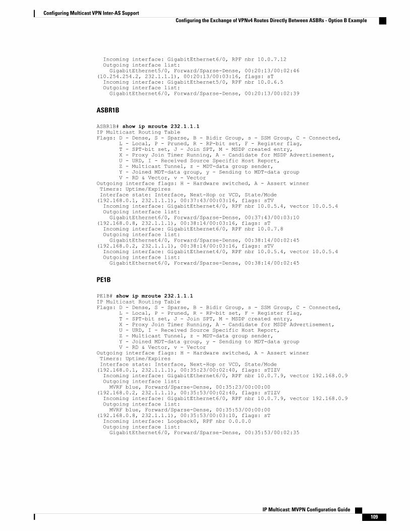
Incoming interface: GigabitEthernet6/0, RPF nbr 10.0.7.12Outgoing interface list:GigabitEthernet5/0, Forward/Sparse-Dense, 00:20:13/00:02:46
(10.254.254.2, 232.1.1.1), 00:20:13/00:03:16, flags: sTIncoming interface: GigabitEthernet5/0, RPF nbr 10.0.6.5Outgoing interface list:GigabitEthernet6/0, Forward/Sparse-Dense, 00:20:13/00:02:39
ASBR1B
ASBR1B# show ip mroute 232.1.1.1IP Multicast Routing TableFlags: D - Dense, S - Sparse, B - Bidir Group, s - SSM Group, C - Connected,
L - Local, P - Pruned, R - RP-bit set, F - Register flag,T - SPT-bit set, J - Join SPT, M - MSDP created entry,X - Proxy Join Timer Running, A - Candidate for MSDP Advertisement,U - URD, I - Received Source Specific Host Report,Z - Multicast Tunnel, z - MDT-data group sender,Y - Joined MDT-data group, y - Sending to MDT-data groupV - RD & Vector, v - Vector
Outgoing interface flags: H - Hardware switched, A - Assert winnerTimers: Uptime/ExpiresInterface state: Interface, Next-Hop or VCD, State/Mode(192.168.0.1, 232.1.1.1), 00:37:43/00:03:16, flags: sTVIncoming interface: GigabitEthernet4/0, RPF nbr 10.0.5.4, vector 10.0.5.4Outgoing interface list:GigabitEthernet6/0, Forward/Sparse-Dense, 00:37:43/00:03:10
(192.168.0.8, 232.1.1.1), 00:38:14/00:03:16, flags: sTIncoming interface: GigabitEthernet6/0, RPF nbr 10.0.7.8Outgoing interface list:GigabitEthernet4/0, Forward/Sparse-Dense, 00:38:14/00:02:45
(192.168.0.2, 232.1.1.1), 00:38:14/00:03:16, flags: sTVIncoming interface: GigabitEthernet4/0, RPF nbr 10.0.5.4, vector 10.0.5.4Outgoing interface list:GigabitEthernet6/0, Forward/Sparse-Dense, 00:38:14/00:02:45
PE1B
PE1B# show ip mroute 232.1.1.1IP Multicast Routing TableFlags: D - Dense, S - Sparse, B - Bidir Group, s - SSM Group, C - Connected,
L - Local, P - Pruned, R - RP-bit set, F - Register flag,T - SPT-bit set, J - Join SPT, M - MSDP created entry,X - Proxy Join Timer Running, A - Candidate for MSDP Advertisement,U - URD, I - Received Source Specific Host Report,Z - Multicast Tunnel, z - MDT-data group sender,Y - Joined MDT-data group, y - Sending to MDT-data groupV - RD & Vector, v - Vector
Outgoing interface flags: H - Hardware switched, A - Assert winnerTimers: Uptime/ExpiresInterface state: Interface, Next-Hop or VCD, State/Mode(192.168.0.1, 232.1.1.1), 00:35:23/00:02:40, flags: sTIZVIncoming interface: GigabitEthernet6/0, RPF nbr 10.0.7.9, vector 192.168.0.9Outgoing interface list:MVRF blue, Forward/Sparse-Dense, 00:35:23/00:00:00
(192.168.0.2, 232.1.1.1), 00:35:53/00:02:40, flags: sTIZVIncoming interface: GigabitEthernet6/0, RPF nbr 10.0.7.9, vector 192.168.0.9Outgoing interface list:MVRF blue, Forward/Sparse-Dense, 00:35:53/00:00:00
(192.168.0.8, 232.1.1.1), 00:35:53/00:03:10, flags: sTIncoming interface: Loopback0, RPF nbr 0.0.0.0Outgoing interface list:GigabitEthernet6/0, Forward/Sparse-Dense, 00:35:53/00:02:35
IP Multicast: MVPN Configuration Guide 109
Configuring Multicast VPN Inter-AS SupportConfiguring the Exchange of VPNv4 Routes Directly Between ASBRs - Option B Example

Configuring the Exchange of VPNv4 Routes Between RRs Using MultihopMP-EBGP
The following example shows how to configure support for MVPN inter-AS option C. This configuration isbased on the sample inter-AS topology illustrated in the figure.
In the configuration example, MP-eBGP is used to exchange VPNv4 routes between RRs of differentautonomous systems with the next hops for these routes exchanged between corresponding ASBR routers.Because the RRs in the two autonomous systems are not directly connected, multihop functionality is requiredto allow them to establishMP-eBGP peering sessions. The PE router next-hop addresses for the VPNv4 routesare exchanged between ASBR routers. In this configuration example, the exchange of these addresses betweenautonomous systems is established using IPv4 BGP label distribution, which enables the ASBRs to distributeIPv4 routes with MPLS labels.
Figure 32: Topology for MVPN Inter-AS Support Option C Configuration Example
The table provides information about the topology used for this inter-AS MVPN Option C configurationexample.
Table 5: Topology Information for MVPN Inter-AS Support Option C Configuration Example
Default MDT (PIM-SSM)Loopback0 InterfacesAS NumberPE, RR, or ASBR Router
232.1.1.110.254.254.2/3255PE1A
232.1.1.110.252.252.4/3255RR1A
232.1.1.110.254.254.6/3255ASBR1A
232.1.1.110.254.254.8/3265PE1B
232.1.1.110.252.252.10/3265RR1B
232.1.1.110.254.254.12/3265ASBR1B
IP Multicast: MVPN Configuration Guide110
Configuring Multicast VPN Inter-AS SupportConfiguring the Exchange of VPNv4 Routes Between RRs Using Multihop MP-EBGP

PE1A
!ip vrf bluerd 55:1111mdt default 232.1.1.1!ip multicast-routingip multicast-routing vrf blueip multicast rpf proxy vector!...!interface GigabitEthernet0/0ip vrf forwarding blueip pim sparse-mode!...!router bgp 55no bgp default route-target filterbgp log-neighbor-changesneighbor 10.252.252.4 remote-as 55neighbor 10.252.252.4 update-source Loopback0!address-family ipv4neighbor 10.252.252.4 activateneighbor 10.252.252.4 send-labelno auto-summaryno synchronizationexit-address-family!address-family ipv4 mdtneighbor 10.252.252.4 activateneighbor 10.252.252.4 send-community extendedexit-address-family!address-family vpnv4neighbor 10.252.252.4 activateneighbor 10.252.252.4 send-community extendedexit-address-family!address-family ipv4 vrf blueredistribute connectedredistribute staticredistribute rip metric 50no synchronizationexit-address-family!...!ip pim ssm default!
RR1A
!router bgp 55neighbor 10.252.252.10 remote-as 65neighbor 10.252.252.10 ebgp-multihop 255neighbor 10.252.252.10 update-source Loopback0neighbor 10.254.254.2 remote-as 55neighbor 10.254.254.2 update-source Loopback0neighbor 10.254.254.6 remote-as 55
IP Multicast: MVPN Configuration Guide 111
Configuring Multicast VPN Inter-AS SupportConfiguring the Exchange of VPNv4 Routes Between RRs Using Multihop MP-EBGP

neighbor 10.254.254.6 update-source Loopback0!address-family ipv4no neighbor 10.252.252.10 activateneighbor 10.254.254.2 activateneighbor 10.254.254.2 route-reflector-clientneighbor 10.254.254.2 send-labelneighbor 10.254.254.6 activateneighbor 10.254.254.6 route-reflector-clientneighbor 10.254.254.6 send-labelno auto-summaryno synchronizationexit-address-family!address-family ipv4 mdtneighbor 10.252.252.10 activateneighbor 10.252.252.10 next-hop-unchangedneighbor 10.254.254.2 activateexit-address-family!address-family vpnv4neighbor 10.252.252.10 activateneighbor 10.252.252.10 send-community extendedneighbor 10.252.252.10 next-hop-unchangedneighbor 10.254.254.2 activateneighbor 10.254.254.2 send-community extendedneighbor 10.254.254.2 route-reflector-clientexit-address-family!
ASBR1A
!ip multicast-routingip multicast-routing vrf blue!...!interface GigabitEthernet7/0ip vrf forwarding blueip pim sparse-mode!...!router bgp 55neighbor 10.0.7.12 remote-as 65neighbor 10.252.252.4 remote-as 55neighbor 10.252.252.4 update-source Loopback0!address-family ipv4redistribute isis level-2 route-map inter-asneighbor 10.0.7.12 activateneighbor 10.0.7.12 route-map IN inneighbor 10.0.7.12 route-map OUT outneighbor 10.0.7.12 send-labelneighbor 10.252.252.4 activateneighbor 10.252.252.4 next-hop-selfneighbor 10.252.252.4 send-labelno auto-summaryno synchronizationexit-address-family!...!
IP Multicast: MVPN Configuration Guide112
Configuring Multicast VPN Inter-AS SupportConfiguring the Exchange of VPNv4 Routes Between RRs Using Multihop MP-EBGP

ip pim ssm default!
ASBR1B
!ip multicast-routingip multicast-routing vrf blue!...!interface GigabitEthernet6/0ip vrf forwarding blueip pim sparse-mode!...!router bgp 65neighbor 10.0.7.6 remote-as 55neighbor 10.252.252.10 remote-as 65neighbor 10.252.252.10 update-source Loopback0!address-family ipv4redistribute isis level-2 route-map inter-asneighbor 10.0.7.6 activateneighbor 10.0.7.6 route-map IN inneighbor 10.0.7.6 route-map OUT outneighbor 10.0.7.6 send-labelneighbor 10.252.252.10 activateneighbor 10.252.252.10 next-hop-selfneighbor 10.252.252.10 send-labelno auto-summaryno synchronizationexit-address-family!...!ip pim ssm default!
RR1B
!router bgp 65no bgp default route-target filterbgp log-neighbor-changesneighbor 10.252.252.4 remote-as 55neighbor 10.252.252.4 ebgp-multihop 255neighbor 10.252.252.4 update-source Loopback0neighbor 10.254.254.8 remote-as 65neighbor 10.254.254.8 update-source Loopback0neighbor 10.254.254.12 remote-as 65neighbor 10.254.254.12 update-source Loopback0!address-family ipv4no neighbor 10.252.252.4 activateneighbor 10.254.254.8 activateneighbor 10.254.254.8 route-reflector-clientneighbor 10.254.254.8 send-labelneighbor 10.254.254.12 activateneighbor 10.254.254.12 route-reflector-clientneighbor 10.254.254.12 send-labelno auto-summary
IP Multicast: MVPN Configuration Guide 113
Configuring Multicast VPN Inter-AS SupportConfiguring the Exchange of VPNv4 Routes Between RRs Using Multihop MP-EBGP

no synchronizationexit-address-family!address-family ipv4 mdtneighbor 10.252.252.4 activateneighbor 10.252.252.4 next-hop-unchangedneighbor 10.254.254.8 activateexit-address-family!address-family vpnv4neighbor 10.252.252.4 activateneighbor 10.252.252.4 send-community extendedneighbor 10.252.252.4 next-hop-unchangedneighbor 10.254.254.8 activateneighbor 10.254.254.8 send-community extendedneighbor 10.254.254.8 route-reflector-clientexit-address-family!
PE1B
!ip vrf bluerd 55:1111mdt default 232.1.1.1!!ip multicast-routingip multicast-routing vrf blueip multicast rpf proxy vector!...!interface GigabitEthernet12/0ip vrf forwarding blueip pim sparse-mode!...!router bgp 65no bgp default route-target filterbgp log-neighbor-changesneighbor 10.252.252.10 remote-as 65neighbor 10.252.252.10 update-source Loopback0!address-family ipv4neighbor 10.252.252.10 activateneighbor 10.252.252.10 send-labelno auto-summaryno synchronizationexit-address-family!address-family ipv4 mdtneighbor 10.252.252.10 activateneighbor 10.252.252.10 send-community extendedexit-address-family!address-family vpnv4neighbor 10.252.252.10 activateneighbor 10.252.252.10 send-community extendedexit-address-family!address-family ipv4 vrf blueredistribute connectedredistribute staticredistribute rip metric 50no synchronization
IP Multicast: MVPN Configuration Guide114
Configuring Multicast VPN Inter-AS SupportConfiguring the Exchange of VPNv4 Routes Between RRs Using Multihop MP-EBGP

exit-address-family!...!ip pim ssm default!The following is sample output from the show ip pim mdt bgp command for PE1A and PE2A. The sampleoutput displays information about the BGP advertisement of RDs forMDT default groups. The output displaysthe MDT default groups advertised, the RDs and source addresses of sources sending to the MDT defaultgroups, the BGP router ID of the advertising routers, and the BGP next hop address contained in theadvertisements.
PE1A# show ip pim mdt bgpMDT (Route Distinguisher + IPv4) Router ID Next HopMDT group 232.1.1.155:1111:10.254.254.8 10.252.252.4 10.254.254.8
PE1B# show ip pim mdt bgpMDT (Route Distinguisher + IPv4) Router ID Next HopMDT group 232.1.1.155:1111:10.254.254.2 10.252.252.10 10.254.254.2
The following is sample output from the show ip mroute proxy command from P1A, P2A, P1B, and P2B.Because P routers learn the RPF Vector from encodings in the PIM join message, PIM is displayed as theorigin under the “Origin” field.
P1A# show ip mroute proxy(10.254.254.8, 232.1.1.1)Proxy Assigner Origin Uptime/Expire10.254.254.6 10.0.2.2 PIM 00:15:37/00:02:57
P2A# show ip mroute proxy(10.254.254.8, 232.1.1.1)Proxy Assigner Origin Uptime/Expire10.254.254.6 10.0.4.3 PIM 00:20:41/00:02:46
P1B# show ip mroute proxy(10.254.254.2, 232.1.1.1)Proxy Assigner Origin Uptime/Expire10.254.254.12 10.0.10.9 PIM 00:29:38/00:02:16
P2B# show ip mroute proxy(10.254.254.2, 232.1.1.1)Proxy Assigner Origin Uptime/Expire10.254.254.12 10.0.12.8 PIM 00:29:58/00:02:09
The following is sample output from the show ipmroute command for PE1A, P1A, P2A, ASBR1A, ASBR1B,P1B, P2B, and PE1B. The sample outputs show the global table for the MDT default group 232.1.1.1. Theoutput from this command confirms that all three PE routers (PE1A, PE2A, and PE1B) have joined the defaultMDT.
PE1A
PE1A# show ip mroute 232.1.1.1IP Multicast Routing TableFlags: D - Dense, S - Sparse, B - Bidir Group, s - SSM Group, C - Connected,
L - Local, P - Pruned, R - RP-bit set, F - Register flag,T - SPT-bit set, J - Join SPT, M - MSDP created entry,X - Proxy Join Timer Running, A - Candidate for MSDP Advertisement,U - URD, I - Received Source Specific Host Report,Z - Multicast Tunnel, z - MDT-data group sender,Y - Joined MDT-data group, y - Sending to MDT-data groupV - RD & Vector, v - Vector
Outgoing interface flags: H - Hardware switched, A - Assert winnerTimers: Uptime/ExpiresInterface state: Interface, Next-Hop or VCD, State/Mode(10.254.254.8, 232.1.1.1), 00:12:27/00:02:43, flags: sTIZvIncoming interface: GigabitEthernet1/0, RPF nbr 10.0.2.3, vector 10.254.254.6Outgoing interface list:
IP Multicast: MVPN Configuration Guide 115
Configuring Multicast VPN Inter-AS SupportConfiguring the Exchange of VPNv4 Routes Between RRs Using Multihop MP-EBGP

MVRF blue, Forward/Sparse-Dense, 00:12:27/00:00:00(10.254.254.2, 232.1.1.1), 00:14:40/00:03:12, flags: sTIncoming interface: Loopback0, RPF nbr 0.0.0.0Outgoing interface list:GigabitEthernet1/0, Forward/Sparse-Dense, 00:12:27/00:03:06
P1A
P1A# show ip mroute 232.1.1.1IP Multicast Routing TableFlags: D - Dense, S - Sparse, B - Bidir Group, s - SSM Group, C - Connected,
L - Local, P - Pruned, R - RP-bit set, F - Register flag,T - SPT-bit set, J - Join SPT, M - MSDP created entry,X - Proxy Join Timer Running, A - Candidate for MSDP Advertisement,U - URD, I - Received Source Specific Host Report,Z - Multicast Tunnel, z - MDT-data group sender,Y - Joined MDT-data group, y - Sending to MDT-data groupV - RD & Vector, v - Vector
Outgoing interface flags: H - Hardware switched, A - Assert winnerTimers: Uptime/ExpiresInterface state: Interface, Next-Hop or VCD, State/Mode(10.254.254.2, 232.1.1.1), 00:15:40/00:03:25, flags: sTIncoming interface: GigabitEthernet1/0, RPF nbr 10.0.2.2Outgoing interface list:GigabitEthernet4/0, Forward/Sparse-Dense, 00:15:40/00:03:24
(10.254.254.8, 232.1.1.1), 00:15:40/00:03:25, flags: sTvIncoming interface: GigabitEthernet4/0, RPF nbr 10.0.4.5, vector 10.254.254.6Outgoing interface list:GigabitEthernet1/0, Forward/Sparse-Dense, 00:15:40/00:03:25
P2A
P2A# show ip mroute 232.1.1.1IP Multicast Routing TableFlags: D - Dense, S - Sparse, B - Bidir Group, s - SSM Group, C - Connected,
L - Local, P - Pruned, R - RP-bit set, F - Register flag,T - SPT-bit set, J - Join SPT, M - MSDP created entry,X - Proxy Join Timer Running, A - Candidate for MSDP Advertisement,U - URD, I - Received Source Specific Host Report,Z - Multicast Tunnel, z - MDT-data group sender,Y - Joined MDT-data group, y - Sending to MDT-data groupV - RD & Vector, v - Vector
Outgoing interface flags: H - Hardware switched, A - Assert winnerTimers: Uptime/ExpiresInterface state: Interface, Next-Hop or VCD, State/Mode(10.254.254.2, 232.1.1.1), 00:20:43/00:03:15, flags: sTIncoming interface: GigabitEthernet4/0, RPF nbr 10.0.4.3Outgoing interface list:GigabitEthernet5/0, Forward/Sparse-Dense, 00:20:43/00:03:15
(10.254.254.8, 232.1.1.1), 00:20:43/00:03:15, flags: sTvIncoming interface: GigabitEthernet5/0, RPF nbr 10.0.6.6, vector 10.254.254.6Outgoing interface list:GigabitEthernet4/0, Forward/Sparse-Dense, 00:20:43/00:03:14
ASBR1A
ASBR1A# show ip mroute 232.1.1.1IP Multicast Routing TableFlags: D - Dense, S - Sparse, B - Bidir Group, s - SSM Group, C - Connected,
L - Local, P - Pruned, R - RP-bit set, F - Register flag,T - SPT-bit set, J - Join SPT, M - MSDP created entry,X - Proxy Join Timer Running, A - Candidate for MSDP Advertisement,U - URD, I - Received Source Specific Host Report,Z - Multicast Tunnel, z - MDT-data group sender,Y - Joined MDT-data group, y - Sending to MDT-data groupV - RD & Vector, v - Vector
Outgoing interface flags: H - Hardware switched, A - Assert winner
IP Multicast: MVPN Configuration Guide116
Configuring Multicast VPN Inter-AS SupportConfiguring the Exchange of VPNv4 Routes Between RRs Using Multihop MP-EBGP

Timers: Uptime/ExpiresInterface state: Interface, Next-Hop or VCD, State/Mode(10.254.254.8, 232.1.1.1), 00:20:13/00:03:16, flags: sTIncoming interface: GigabitEthernet6/0, RPF nbr 10.0.7.12Outgoing interface list:GigabitEthernet5/0, Forward/Sparse-Dense, 00:20:13/00:02:46
(10.254.254.2, 232.1.1.1), 00:20:13/00:03:16, flags: sTIncoming interface: GigabitEthernet5/0, RPF nbr 10.0.6.5Outgoing interface list:GigabitEthernet6/0, Forward/Sparse-Dense, 00:20:13/00:02:39
ASBR1B
ASBR1B# show ip mroute 232.1.1.1IP Multicast Routing TableFlags: D - Dense, S - Sparse, B - Bidir Group, s - SSM Group, C - Connected,
L - Local, P - Pruned, R - RP-bit set, F - Register flag,T - SPT-bit set, J - Join SPT, M - MSDP created entry,X - Proxy Join Timer Running, A - Candidate for MSDP Advertisement,U - URD, I - Received Source Specific Host Report,Z - Multicast Tunnel, z - MDT-data group sender,Y - Joined MDT-data group, y - Sending to MDT-data groupV - RD & Vector, v - Vector
Outgoing interface flags: H - Hardware switched, A - Assert winnerTimers: Uptime/ExpiresInterface state: Interface, Next-Hop or VCD, State/Mode(10.254.254.8, 232.1.1.1), 00:25:46/00:03:13, flags: sTIncoming interface: GigabitEthernet7/0, RPF nbr 10.0.8.11Outgoing interface list:GigabitEthernet6/0, Forward/Sparse-Dense, 00:25:46/00:03:04
(10.254.254.2, 232.1.1.1), 00:25:46/00:03:13, flags: sTIncoming interface: GigabitEthernet6/0, RPF nbr 10.0.7.6Outgoing interface list:GigabitEthernet7/0, Forward/Sparse-Dense, 00:25:46/00:03:07
P1B
P1B# show ip mroute 232.1.1.1IP Multicast Routing TableFlags: D - Dense, S - Sparse, B - Bidir Group, s - SSM Group, C - Connected,
L - Local, P - Pruned, R - RP-bit set, F - Register flag,T - SPT-bit set, J - Join SPT, M - MSDP created entry,X - Proxy Join Timer Running, A - Candidate for MSDP Advertisement,U - URD, I - Received Source Specific Host Report,Z - Multicast Tunnel, z - MDT-data group sender,Y - Joined MDT-data group, y - Sending to MDT-data groupV - RD & Vector, v - Vector
Outgoing interface flags: H - Hardware switched, A - Assert winnerTimers: Uptime/ExpiresInterface state: Interface, Next-Hop or VCD, State/Mode(10.254.254.8, 232.1.1.1), 00:29:41/00:03:17, flags: sTIncoming interface: GigabitEthernet10/0, RPF nbr 10.0.10.9Outgoing interface list:GigabitEthernet7/0, Forward/Sparse-Dense, 00:29:41/00:02:56
(10.254.254.2, 232.1.1.1), 00:29:41/00:03:17, flags: sTvIncoming interface: GigabitEthernet7/0, RPF nbr 10.0.8.12, vector 10.254.254.12Outgoing interface list:GigabitEthernet10/0, Forward/Sparse-Dense, 00:29:41/00:02:44
P2B
P2B# show ip mroute 232.1.1.1IP Multicast Routing TableFlags: D - Dense, S - Sparse, B - Bidir Group, s - SSM Group, C - Connected,
L - Local, P - Pruned, R - RP-bit set, F - Register flag,T - SPT-bit set, J - Join SPT, M - MSDP created entry,X - Proxy Join Timer Running, A - Candidate for MSDP Advertisement,
IP Multicast: MVPN Configuration Guide 117
Configuring Multicast VPN Inter-AS SupportConfiguring the Exchange of VPNv4 Routes Between RRs Using Multihop MP-EBGP

U - URD, I - Received Source Specific Host Report,Z - Multicast Tunnel, z - MDT-data group sender,Y - Joined MDT-data group, y - Sending to MDT-data groupV - RD & Vector, v - Vector
Outgoing interface flags: H - Hardware switched, A - Assert winnerTimers: Uptime/ExpiresInterface state: Interface, Next-Hop or VCD, State/Mode(10.254.254.8, 232.1.1.1), 00:30:01/00:03:25, flags: sTIncoming interface: GigabitEthernet11/0, RPF nbr 10.0.12.8Outgoing interface list:GigabitEthernet10/0, Forward/Sparse-Dense, 00:30:01/00:02:30
(10.254.254.2, 232.1.1.1), 00:30:01/00:03:25, flags: sTvIncoming interface: GigabitEthernet10/0, RPF nbr 10.0.10.11, vector 10.254.254.12Outgoing interface list:GigabitEthernet11/0, Forward/Sparse-Dense, 00:30:01/00:02:36
PE1B
PE1B# show ip mroute 232.1.1.1IP Multicast Routing TableFlags: D - Dense, S - Sparse, B - Bidir Group, s - SSM Group, C - Connected,
L - Local, P - Pruned, R - RP-bit set, F - Register flag,T - SPT-bit set, J - Join SPT, M - MSDP created entry,X - Proxy Join Timer Running, A - Candidate for MSDP Advertisement,U - URD, I - Received Source Specific Host Report,Z - Multicast Tunnel, z - MDT-data group sender,Y - Joined MDT-data group, y - Sending to MDT-data groupV - RD & Vector, v - Vector
Outgoing interface flags: H - Hardware switched, A - Assert winnerTimers: Uptime/ExpiresInterface state: Interface, Next-Hop or VCD, State/Mode(10.254.254.2, 232.1.1.1), 00:31:22/00:02:55, flags: sTIZvIncoming interface: GigabitEthernet11/0, RPF nbr 10.0.12.9, vector 10.254.254.12Outgoing interface list:MVRF blue, Forward/Sparse-Dense, 00:31:22/00:00:00
(10.254.254.8, 232.1.1.1), 00:33:35/00:03:25, flags: sTIncoming interface: Loopback0, RPF nbr 0.0.0.0Outgoing interface list:GigabitEthernet11/0, Forward/Sparse-Dense, 00:31:22/00:03:22
Additional ReferencesRelated Documents
Document TitleRelated Topic
Cisco IOS IP Multicast Command ReferenceMulticast commands: complete command syntax,command mode, command history, defaults, usageguidelines, and examples
Standards
TitleStandard
The RPF Vector TLVdraft-ietf-pim-rpf-vector
BGP/MPLS IP VPNsdraft-ietf-l3vpn-rfc2547bis1
IP Multicast: MVPN Configuration Guide118
Configuring Multicast VPN Inter-AS SupportAdditional References

1 The Internet draft standard draft-ietf-l3vpn-rfc2547bis is generally referred to as RFC 2547bis.
MIBs
MIBs LinkMIB
To locate and downloadMIBs for selected platforms,Cisco IOS releases, and feature sets, use Cisco MIBLocator found at the following URL:
http://www.cisco.com/go/mibs
No new or modifiedMIBs are supported, and supportfor existing MIBs has not been modified.
RFCs
TitleRFC
BGP/MPLS IP Virtual Private Networks (VPN)RFC 43642
The Reverse Path Forwarding (RPF) Vector TLVRFC 5496
2 RFC 4364 is the latest RFC standard and obsoletes RFC 2547 (and the later RFC2547bis Internet draft standard).
Technical Assistance
LinkDescription
http://www.cisco.com/techsupportThe Cisco Support website provides extensive onlineresources, including documentation and tools fortroubleshooting and resolving technical issues withCisco products and technologies.
To receive security and technical information aboutyour products, you can subscribe to various services,such as the Product Alert Tool (accessed from FieldNotices), the Cisco Technical Services Newsletter,and Really Simple Syndication (RSS) Feeds.
Access to most tools on the Cisco Support websiterequires a Cisco.com user ID and password.
Feature Information for Configuring Multicast VPN Inter-ASSupport
The following table provides release information about the feature or features described in this module. Thistable lists only the software release that introduced support for a given feature in a given software releasetrain. Unless noted otherwise, subsequent releases of that software release train also support that feature.
IP Multicast: MVPN Configuration Guide 119
Configuring Multicast VPN Inter-AS SupportFeature Information for Configuring Multicast VPN Inter-AS Support

Use Cisco Feature Navigator to find information about platform support and Cisco software image support.To access Cisco Feature Navigator, go to www.cisco.com/go/cfn. An account on Cisco.com is not required.
Table 6: Feature Information for Configuring Multicast VPN Inter-AS Support
Feature InformationReleasesFeature Name
The BGP Multicast Inter-AS VPNfeature introduces the IPv4 MDTSAFI in BGP. The MDT SAFI isa transitive multicast capableconnector attribute that is definedas an IPv4 address family in BGP.The MDT SAFI is designed tosupport inter-AS VPN peeringsessions.
The following commands wereintroduced or modified by thisfeature: address-family ipv4(BGP), clear bgp ipv4 mdt, showip bgp ipv4.
12.0(29)S
12.2(33)SRA
12.2(31)SB2
12.2(33)SXH
12.4(20)T
15.0(1)S
BGP Multicast Inter-AS VPN
The Multicast VPN Inter-ASsupport feature enablesMDTs usedfor MVPNs to span multipleautonomous systems. Benefitsinclude increased multicastcoverage to customers that requiremulticast to span multiple serviceproviders in an MPLS Layer 3VPN service with the flexibility tosupport all options described inRFC 4364. Additionally, theMulticast VPN Inter-AS Supportfeature may be used to consolidatean existing MVPN service withanotherMVPN service, such as thecase with a company merger oracquisition.
The following commands wereintroduced or modified by thisfeature: ip multicast rpf proxyvector, and show ipmroute, showip pim neighbor, show ip rpf.
12.0(30)S
12.2(33)SRA
12.2(31)SB2
12.2(33)SXH
12.4(20)T
15.0(1)S
Multicast VPN Inter-AS Support
IP Multicast: MVPN Configuration Guide120
Configuring Multicast VPN Inter-AS SupportFeature Information for Configuring Multicast VPN Inter-AS Support

C H A P T E R 5MVPN mLDP Partitioned MDT
The MVPN mLDP partitioned MDT feature uses Upstream Multicast Hop-Provider Multicast ServiceInterface (UMS-PMSI), a subset of provider edge routers (PEs) to transmit data to other PEs; similar to theusage of multiple selective-PMSI (S-PMSI) by data multicast distribution tree (MDT). In the partitionedMDT approach, egress PE routers that have interested receivers for traffic from a particular ingress PE joinsa point-to-point (P2P) connection rooted at that ingress PE. This makes the number of ingress PE routers ina network to be low resulting in a limited number of trees in the core.
• Finding Feature Information, page 121
• Prerequisites for MVPN mLDP Partitioned MDT , page 121
• Restrictions for MVPN mLDP Partitioned MDT, page 122
• Information About MVPN mLDP Partitioned MDT, page 122
• How to Configure MVPN mLDP Partitioned MDT, page 123
• Configuration Examples for MVPN mLDP Partitioned MDT, page 125
• Additional References for MVPN mLDP Partitioned MDT, page 126
• Feature Information for MVPN mLDP Partitioned MDT, page 126
Finding Feature InformationYour software release may not support all the features documented in this module. For the latest caveats andfeature information, see Bug Search Tool and the release notes for your platform and software release. Tofind information about the features documented in this module, and to see a list of the releases in which eachfeature is supported, see the feature information table.
Use Cisco Feature Navigator to find information about platform support and Cisco software image support.To access Cisco Feature Navigator, go to www.cisco.com/go/cfn. An account on Cisco.com is not required.
Prerequisites for MVPN mLDP Partitioned MDTMVPN BGP auto discovery should be configured.
IP Multicast: MVPN Configuration Guide 121

Restrictions for MVPN mLDP Partitioned MDT• PIM Dense mode (except for Auto-RP) and PIM-Bidir in the VRF are not supported.
• BGP multicast signaling is supported and PIM signaling is not supported.
• Only point-to-multi point (P2MP) mLDP label switch path is supported.
• Same VRF (for which mLDP in-band signaling is configured) needs to be configured on IPv4
•• Rosen mLDP recursive FEC is not supported. Partitioned MDT is applicable to inter-AS VPN (InterAS option B and option C are not supported).
• mLDP filtering is not supported.
• Only interface-based strict RPF is supported with partitioned MDT.
Information About MVPN mLDP Partitioned MDT
Overview of MVPN mLDP Partitioned MDTMVPN allows a service provider to configure and support multicast traffic in an MPLS VPN environment.This type supports routing and forwarding of multicast packets for each individual VPN routing and forwarding(VRF) instance, and it also provides a mechanism to transport VPN multicast packets across the serviceprovider backbone. In the MLDP case, the regular label switch path forwarding is used, so core does not needto run PIM protocol. In this scenario, the c-packets are encapsulated in the MPLS labels and forwarding isbased on the MPLS Label Switched Paths (LSPs).
TheMVPNmLDP service allows you to build a Protocol IndependentMulticast (PIM) domain that has sourcesand receivers located in different sites.
To provide Layer 3 multicast services to customers with multiple distributed sites, service providers look fora secure and scalable mechanism to transmit customer multicast traffic across the provider network. MulticastVPN (MVPN) provides such services over a shared service provider backbone, using native multicasttechnology similar to BGP/MPLS VPN.
MVPN emulates MPLS VPN technology in its adoption of the multicast domain (MD) concept, in whichprovider edge (PE) routers establish virtual PIM neighbor connections with other PE routers that are connectedto the same customer VPN. These PE routers thereby form a secure, virtual multicast domain over the providernetwork. Multicast traffic is then transmitted across the core network from one site to another, as if the trafficwere going through a dedicated provider network.
Separate multicast routing and forwarding tables are maintained for each VPN routing and forwarding (VRF)instance, with traffic being sent through VPN tunnels across the service provider backbone.
In the Rosen MVPN mLDP solution, a multipoint-to-multipoint (MP2MP) default MDT is setup to carrycontrol plane and data traffic. A disadvantage with this solution is that all PE routers that are part of theMVPNneed to join this default MDT tree. Setting up a MP2MP tree between all PE routers of a MVPN is equivalentto creating N P2MP trees rooted at each PE (Where N is the number of PE routers). In an Inter-AS (OptionA) solution this problem is exacerbated since all PE routers across all AS’es need to join the default MDT.
IP Multicast: MVPN Configuration Guide122
MVPN mLDP Partitioned MDTRestrictions for MVPN mLDP Partitioned MDT

Another disadvantage of this solution is that any packet sent through a default MDT reaches all the PE routerseven if there is no requirement.
In the partitioned MDT approach, only those egress PE routers that receive traffic requests from a particularingress PE join the PMSI configured at that ingress PE. This makes the number of ingress PE routers in anetwork to be low resulting in a limited number of trees in the core.
How to Configure MVPN mLDP Partitioned MDT
Configuring MVPN mLDP Partitioned MDT
SUMMARY STEPS
1. enable2. configure terminal3. ip multicast-routing vrf vrf-name4. ip vrf vrf-name5. rd route-distinguisher6. route target export route-target-ext-community7. route target import route-target-ext-community8. mdt strict-rpf interface9. mdt partitioned mldp p2mp10. mdt auto-discovery mldp [inter-as]11. exit12. show ip pim mdt13. show ip pim vrf mdt [send | receive]14. show ip multicast mpls vif
DETAILED STEPS
PurposeCommand or Action
Enables privileged EXEC mode.enableStep 1
Example:
Device> enable
• Enter your password if prompted.
Enters global configuration mode.configure terminal
Example:
Device# configure terminal
Step 2
IP Multicast: MVPN Configuration Guide 123
MVPN mLDP Partitioned MDTHow to Configure MVPN mLDP Partitioned MDT

PurposeCommand or Action
Enables IP multicast routing for the MVPN VRF specifiedfor the vrf-name argument.
ip multicast-routing vrf vrf-name
Example:
Device(config)# ip multicast-routing vrf VRF
Step 3
Defines a VRF instance and enters VRF configurationmode.
ip vrf vrf-name
Example:
Device(config-vrf)# ip vrf VRF
Step 4
Creates a route distinguisher (RD) (in order to make theVRF functional).
rd route-distinguisher
Example:
Device(config-vrf)# rd 50:11
Step 5
• Creates the routing and forwarding tables, associatesthe RD with the VRF instance, and specifies thedefault RD for a VPN.
Creates an export route target extended community for thespecified VRF.
route target export route-target-ext-community
Example:
Device(config-vrf)# route target export 100:100
Step 6
Creates an import route target extended community for thespecified VRF.
route target import route-target-ext-community
Example:
Device(config-vrf)# route target import 100:100
Step 7
Creates per-PE LSPVIF interface to implement strict-RPFcheck.
mdt strict-rpf interface
Example:
Device(config-vrf)# mdt strict-rpf interface
Step 8
Configures partitioned MDT.mdt partitioned mldp p2mpStep 9
Example:
Device(config-vrf)# mdt partitioned mldp p2mp
•
Enables inter-AS operation with BGP A-D.mdt auto-discovery mldp [inter-as]
Example:
Device(config-vrf)# mdt auto-discovery mldpinter-as
Step 10
IP Multicast: MVPN Configuration Guide124
MVPN mLDP Partitioned MDTConfiguring MVPN mLDP Partitioned MDT

PurposeCommand or Action
Exits the VRF configurationmode and returns to privilegedEXEC mode.
exit
Example:
Device(config-vrf)# exit
Step 11
Displays information on wildcard S-PMSI A-D route.show ip pim mdt
Example:
Device# show ip pim mdt
Step 12
Displays information on wildcard S-PMSI A-D route alongwithMDT group mappings received from other PE routersor the MDT groups that are currently in use.
show ip pim vrf mdt [send | receive]
Example:
Device# show ip pim vrf mdt send
Step 13
Displays the LSPVIFs created for all the PEs.show ip multicast mpls vif
Example:
Device# end
Step 14
Configuration Examples for MVPN mLDP Partitioned MDT
Example: MVPN mLDP Partitioned MDT
ip multicast-routing vrf VRFip vrf VRFrd 50:11route target export 100:100route target import 100:100mdt strict-rpf interfacemdt partitioned mldp p2mpmdt auto-discovery mldp inter-as!!
IP Multicast: MVPN Configuration Guide 125
MVPN mLDP Partitioned MDTConfiguration Examples for MVPN mLDP Partitioned MDT

Additional References for MVPN mLDP Partitioned MDTRelated Documents
Document TitleRelated Topic
Cisco IOS Master Commands List, All ReleasesCisco IOS commands
Cisco IP Multicast Command ReferenceIP multicast commands
IP Multicast: MVPN Configuration GuideConfiguring Multicast VPN Inter-AS Support
IP Multicast: LSM Configuration GuideConfiguring MLDP-based MVPN
Technical Assistance
LinkDescription
http://www.cisco.com/cisco/web/support/index.htmlThe Cisco Support and Documentation websiteprovides online resources to download documentation,software, and tools. Use these resources to install andconfigure the software and to troubleshoot and resolvetechnical issues with Cisco products and technologies.Access to most tools on the Cisco Support andDocumentation website requires a Cisco.com user IDand password.
Feature Information for MVPN mLDP Partitioned MDTThe following table provides release information about the feature or features described in this module. Thistable lists only the software release that introduced support for a given feature in a given software releasetrain. Unless noted otherwise, subsequent releases of that software release train also support that feature.
Use Cisco Feature Navigator to find information about platform support and Cisco software image support.To access Cisco Feature Navigator, go to www.cisco.com/go/cfn. An account on Cisco.com is not required.
IP Multicast: MVPN Configuration Guide126
MVPN mLDP Partitioned MDTAdditional References for MVPN mLDP Partitioned MDT

Table 7: Feature Information for MVPN mLDP Partitioned MDT
Feature InformationReleasesFeature Name
In the partitioned MDT approach,only those egress PE routers thatreceive traffic requests from aparticular ingress PE join a S-PMSIconfigured at that ingress PE.Typically the number of ingress PErouters in a network is lowresulting in a limited number oftrees in the core.
No commands were introduced ormodified.
15.4(1)TMVPN mLDP Partitioned MDT
IP Multicast: MVPN Configuration Guide 127
MVPN mLDP Partitioned MDTFeature Information for MVPN mLDP Partitioned MDT

IP Multicast: MVPN Configuration Guide128
MVPN mLDP Partitioned MDTFeature Information for MVPN mLDP Partitioned MDT

C H A P T E R 6Nextgen MVPN BGP C-Route Signaling
TheNext-generationMVPNBGPC-Route Signaling feature provides a simpler solution to configuremulticastover Layer 3 VPNs using BGP for C-multicast signaling. The MVPN BGP C-Route Full SM Support optionuses BGP to signal the customer multicast routes. Sending the multicast routes over BGP avoids the needfor the periodic refresh of the routes since BGP uses a reliable transport. This module provides informationfor configuring the Next-generation MVPN BGP C-Route Signaling feature with the MVPN BGP C-RouteFull SM Support option.
• Nextgen MVPN BGP C-Route Signaling, page 129
• Finding Feature Information, page 129
• Restrictions for Nextgen MVPN BGP C-Route Signaling, page 130
• Information About Nextgen MPVN BGP C-Route Signaling , page 130
• How to Configure Nextgen MVPN BGP C-Route Signaling, page 131
• Configuration Examples for Nextgen MVPN BGP C-Route Signaling, page 134
• Additional References for Nextgen MVPN BGP C-Route Signaling, page 135
• Feature Infomation for Nextgen MVPN BGP C-Route Signaling, page 135
Nextgen MVPN BGP C-Route SignalingThe Next-generationMVPNBGPC-Route Signaling feature provides a simpler solution to configure multicastover Layer 3 VPNs using BGP for C-multicast signaling. The MVPN BGP C-Route Full SM Support optionuses BGP to signal the customer multicast routes. Sending the multicast routes over BGP avoids the need forthe periodic refresh of the routes since BGP uses a reliable transport. This module provides information forconfiguring the Next-generation MVPN BGP C-Route Signaling feature with the MVPN BGP C-Route FullSM Support option.
Finding Feature InformationYour software release may not support all the features documented in this module. For the latest caveats andfeature information, see Bug Search Tool and the release notes for your platform and software release. To
IP Multicast: MVPN Configuration Guide 129

find information about the features documented in this module, and to see a list of the releases in which eachfeature is supported, see the feature information table.
Use Cisco Feature Navigator to find information about platform support and Cisco software image support.To access Cisco Feature Navigator, go to www.cisco.com/go/cfn. An account on Cisco.com is not required.
Restrictions for Nextgen MVPN BGP C-Route SignalingThe following multicast features are not supported by MVPN BGP C-route signaling :
• BGP signaling with mLDP Transport
• Inter-AS scenarios with BGP signaling
• Dense mode in the VRF
• Extranets with BGP Signaling
• Full ASM Mode (SM and Bidir) in the VRF
• IPv6 in the VRF with mLDP Transport
• BGP Non Stop Routing (NSR)
• Inter-AD for GRE and IP-IP MVPN transport
• Migration/Hybrid solution between PIM Signaling and BGP Signaling
• Static mroutes used in conjunction with BGP signaling
Information About Nextgen MPVN BGP C-Route Signaling
Overview of MVPN BGP C-Route Full SM SupportA service provider determines whether a particular VPN is multicast-enabled. If it is, it corresponds to a"multicast domain". A PE that attaches to a particular multicast-enabled VPN is said to belong to thecorresponding multicast domain. For each multicast domain, there is a default "Multicast Distribution Tree(MDT)" through the backbone, connecting all of the PEs that belong to that multicast domain. A given PEmay be in as many multicast domains as there are VPNs attached to that PE. However, each multicast domainhas its own MDT. The MDTs are created by running PIM in the backbone, and in general an MDT alsoincludes P routers on the paths between the PE routers.
The default MDT for a multicast domain is constructed automatically as the PEs in the domain come up.Construction of the default MDT does not depend on the existence of multicast traffic in the domain; it willexist before any such multicast traffic is seen. Default MDTs correspond to the "MI-PMSIs" of MVPN.
In MVPNs, each CE router is a unicast routing adjacency of a PE router, but CE routers at different sites donot become unicast routing adjacencies of each other. This important characteristic is retained for multicastrouting—a CE router becomes a PIM adjacency of a PE router, but CE routers at different sites do not becomePIM adjacencies of each other. Multicast packets from within a VPN are received from a CE router by aningress PE router. The ingress PE encapsulates the multicast packets and forwards them along the defaultMDT tree to all the PE routers connected to sites of the given VPN. Every PE router attached to a site of the
IP Multicast: MVPN Configuration Guide130
Nextgen MVPN BGP C-Route SignalingRestrictions for Nextgen MVPN BGP C-Route Signaling

given VPN thus receives all multicast packets from within that VPN. If a particular PE routers is not on thepath to any receiver of that multicast group, the PE simply discards that packet.
If a large amount of traffic is being sent to a particular multicast group, but that group does not have receiversat all the VPN sites, it may not be needed to forward that group's traffic along the default MDT. Therefore, amethod is specified for establishing individual MDTs for specific multicast groups called as "Data MDTs".A data MDT delivers VPN data traffic for a particular multicast group only to those PE routers that are onthe path to receivers of that multicast group. Using a data MDT has the benefit of reducing the amount ofmulticast traffic on the backbone, as well reducing the load on some of the PEs; it has the disadvantage ofincreasing the amount of state that must be maintained by the P routers. The service provider has completecontrol over this tradeoff. Data MDTs correspond to the S-PMSIs of MVPN.
An enterprise that uses PIM-based multicasting in its network can migrate from a private network to aBGP/MPLS IPVPN service, while continuing to use whatever multicast router configurations it was previouslyusing; no changes need be made to CE routers or to other routers at customer sites. For instance, any dynamicRP-discovery procedures that are already in use may be left in place.
The BGPMVPN signalingmechanism does not use theMDT tunnel for signaling. The BGP signaling separatesthe control-plane and the data-plane for MVPN multicast c-route exchange. The MVPN BGP C-Route FullSM Support feature helps the service providers to leverage the existing BGP operation experience for deployingMVPN services.
For more details see Cisco Systems' Solution for Multicast in MPLS/BGP IP VPNs.
How to Configure Nextgen MVPN BGP C-Route Signaling
Configuring the MVPN BGP C-Route Signaling
SUMMARY STEPS
1. enable2. configure terminal3. router bgp autonomous-system-number4. address-family {ipv4 | ipv6}mvpn5. mvpn single-forwarder-selection highest-ip-address single-forwarder-selection highest-ip-address6. mdt overlay use-bgp7. end8. configure terminal9. ip multicast-routing vrf vrf-name10. ip vrfvrf-name11. mdt auto-discovery [pim |mldp [inter-as]] [ pim-tlv-announce]12. mdt overlay bgp shared-tree-prune-delay seconds13. mdt overlay bgp source-tree-prune-delay seconds14. end
IP Multicast: MVPN Configuration Guide 131
Nextgen MVPN BGP C-Route SignalingHow to Configure Nextgen MVPN BGP C-Route Signaling

DETAILED STEPS
PurposeCommand or Action
Enables privileged EXEC mode.enableStep 1
Example:Device> enable
• Enter your password if prompted.
Enters global configuration mode.configure terminal
Example:Device# configure terminal
Step 2
Enters BGP router configuration mode and creates aBGP routing process.
router bgp autonomous-system-number
Example:Device(config)# router bgp 65538
Step 3
Enters address family configuration mode and enablesC-route signaling.
address-family {ipv4 | ipv6}mvpn
Example:Device(config-router)# address-family ipv4 mvpn
Step 4
Configures the BGP MVPN Upstream Multicast Hop(UMH) via the highest IP address.
mvpn single-forwarder-selection highest-ip-addresssingle-forwarder-selection highest-ip-address
Example:Device(config-router-af)# mvpnsingle-forwarder-selection highest-ip-address
Step 5
Specifies BGP as the overlay protocol.mdt overlay use-bgp
Example:Device(config-router-af)# mdt overlay use-bgp
Step 6
Exits address family configuration mode and returns toprivileged EXEC mode.
end
Example:Device(config-router-af)# end
Step 7
Enters global configuration mode.configure terminal
Example:Device# configure terminal
Step 8
IP Multicast: MVPN Configuration Guide132
Nextgen MVPN BGP C-Route SignalingConfiguring the MVPN BGP C-Route Signaling
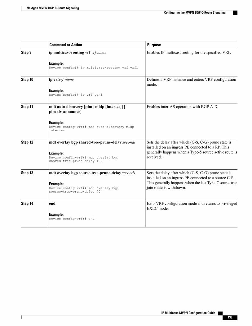
PurposeCommand or Action
Enables IP multicast routing for the specified VRF.ip multicast-routing vrf vrf-name
Example:Device(config)# ip multicast-routing vrf vrf1
Step 9
Defines a VRF instance and enters VRF configurationmode.
ip vrfvrf-name
Example:Device(config)# ip vrf vpn1
Step 10
Enables inter-AS operation with BGP A-D.mdt auto-discovery [pim |mldp [inter-as]] [pim-tlv-announce]
Step 11
Example:Device(config-vrf)# mdt auto-discovery mldpinter-as
Sets the delay after which (C-S, C-G) prune state isinstalled on an ingress PE connected to a RP. This
mdt overlay bgp shared-tree-prune-delay seconds
Example:Device(config-vrf)# mdt overlay bgpshared-tree-prune-delay 100
Step 12
generally happens when a Type-5 source active route isreceived.
Sets the delay after which (C-S, C-G) prune state isinstalled on an ingress PE connected to a source C-S.
mdt overlay bgp source-tree-prune-delay seconds
Example:Device(config-vrf)# mdt overlay bgpsource-tree-prune-delay 70
Step 13
This generally happens when the last Type-7 source treejoin route is withdrawn.
Exits VRF configurationmode and returns to privilegedEXEC mode.
end
Example:Device(config-vrf)# end
Step 14
IP Multicast: MVPN Configuration Guide 133
Nextgen MVPN BGP C-Route SignalingConfiguring the MVPN BGP C-Route Signaling

Displaying Information About MVPN BGP C-Route Signaling
SUMMARY STEPS
1. enable2. configure terminal3. show bgp [ipv4 | ipv6] mvpn [route-type route-type originator ID] [vrf vrf name] [all | prefix]4. show {ipv4 | ipv6} pim [vrf vrf-name] mdt [c-mroutes | source-active] [group | source]
DETAILED STEPS
PurposeCommand or Action
Enables privileged EXEC mode.enableStep 1
Example:Device> enable
• Enter your password if prompted.
Enters global configuration mode.configure terminal
Example:Device# configure terminal
Step 2
Displays the route type, VRF name, and MVPNoptions for BGP MVPN C-route signaling.
show bgp [ipv4 | ipv6]mvpn [route-type route-type originatorID] [vrf vrf name] [all | prefix]
Example:Device# show bgp ipv4 mvpn route-type 1 1.1.1.1 all
Step 3
Displays all routes—learnt and originated from thePE.
show {ipv4 | ipv6} pim [vrf vrf-name] mdt [c-mroutes |source-active] [group | source]
Example:Device# show ipv4 pim vrf vrf1 mdt c-mroutes
Step 4
Configuration Examples for Nextgen MVPN BGP C-RouteSignaling
Example: MVPN BGP C-Route Full SM Support
router bgp 65538
IP Multicast: MVPN Configuration Guide134
Nextgen MVPN BGP C-Route SignalingDisplaying Information About MVPN BGP C-Route Signaling

address-family ipv4 mvpnmvpn single-forwarder-selection highest-ip-addressmdt overlay use-bgp!ip multicast-routing vrf vrf1ip vrf cicsvpnmdt auto-discovery mldp inter-asmdt overlay bgp shared-tree-prune-delay 100mdt overlay bgp source-tree-prune-delay 70!!
Additional References for Nextgen MVPN BGP C-RouteSignaling
Related Documents
Document TitleRelated Topic
Cisco IOSMaster Commands List,All Releases
Cisco IOS commands
Cisco IOS IP Multicast CommandReference
IP multicast commands
Technical Assistance
LinkDescription
http://www.cisco.com/cisco/web/support/index.htmlThe Cisco Support and Documentation websiteprovides online resources to download documentation,software, and tools. Use these resources to install andconfigure the software and to troubleshoot and resolvetechnical issues with Cisco products and technologies.Access to most tools on the Cisco Support andDocumentation website requires a Cisco.com user IDand password.
Feature Infomation for Nextgen MVPN BGP C-Route SignalingThe following table provides release information about the feature or features described in this module. Thistable lists only the software release that introduced support for a given feature in a given software releasetrain. Unless noted otherwise, subsequent releases of that software release train also support that feature.
Use Cisco Feature Navigator to find information about platform support and Cisco software image support.To access Cisco Feature Navigator, go to www.cisco.com/go/cfn. An account on Cisco.com is not required.
IP Multicast: MVPN Configuration Guide 135
Nextgen MVPN BGP C-Route SignalingAdditional References for Nextgen MVPN BGP C-Route Signaling

Table 8: Feature Information for Nextgen MVPN BGP C-Route Signaling
Feature InformationReleasesFeature Name
The Next-generationMVPN BGP C-RouteSignaling feature providesa simpler solution toconfigure multicast overLayer 3 VPNs using BGPfor C-multicast signaling.
Nextgen MPVN BGP C-RouteSignaling
IP Multicast: MVPN Configuration Guide136
Nextgen MVPN BGP C-Route SignalingFeature Infomation for Nextgen MVPN BGP C-Route Signaling

C H A P T E R 7BGP MVPN PE-PE Ingress Replication
The BGP-mVPN PE-PE Ingress Replication feature enables creating a Point-to-Multipoint (P2MP) treewhere ingress devices replicate the multicast packets, encapsulate the packets in a unicast tunnel and sendthe packets to egress devices.
• Finding Feature Information, page 137
• Prerequisites for BGP MVPN PE-PE Ingress Replication, page 137
• Restrictions for BGP MVPN PE-PE Ingress Replication, page 138
• Information about BGP MVPN PE-PE Ingress Replication , page 138
• How to Configure BGP MVPN PE-PE Ingress Replication, page 141
• Additional References for BGP MVPN PE-PE Ingress Replication, page 143
• Feature Information for BGP MVPN PE-PE Ingress Replication, page 144
Finding Feature InformationYour software release may not support all the features documented in this module. For the latest caveats andfeature information, see Bug Search Tool and the release notes for your platform and software release. Tofind information about the features documented in this module, and to see a list of the releases in which eachfeature is supported, see the feature information table.
Use Cisco Feature Navigator to find information about platform support and Cisco software image support.To access Cisco Feature Navigator, go to www.cisco.com/go/cfn. An account on Cisco.com is not required.
Prerequisites for BGP MVPN PE-PE Ingress Replication• Label switched paths (LSPs) are assumed to exist between PE routers ("PEs").
• Multiprotocol Label Switching (MPLS) Label Distribution Protocol (LDP) and unicast routing must beenabled.
IP Multicast: MVPN Configuration Guide 137

Restrictions for BGP MVPN PE-PE Ingress Replication• For Cisco IOS XE Denali 16.3.1 the PE to PE Ingress Replication (PE-PE IR) is only supported on theCisco CSR 1000v Series Cloud Services Router.
• The Partitioned MDT IR profile only supports MVPN BGP C-Route Signaling.
• Inter-AS option C is only supported.
• High Availability is not supported.
• BGP Auto Discovery (AD) must be used for PE-PE IR.
• The Partitioned-MDT profile supports only BGP C-multicast route signaling. The Default-MDT profilesupports both BGP and PIM C-multicast signaling. The Data-MDT profile is also supported.
• Only PIM ASM and SSM are supported for deployments of multicast control plane protocols. PIMBIDIR and PIM Dense-mode are not supported.
Information about BGP MVPN PE-PE Ingress ReplicationIn Multicast VPN (MVPN) using Multipoint to Multipoint LDP (MLDP), multicast traffic received by aningress provider edge (PE) router is replicated/copied and passes through the core to egress PE routers. Stateis maintained in the core and this may lead to some dynamic fluctuation of state in the service provider corerouters.
In PE to PE IR, multicast traffic from an ingress PE router is replicated/copied and tunneled over multipleLSPs directly from the ingress PE to egress PE. State is not maintained as the traffic passes through the core.
The primary advantage of using PE to PE Ingress Replication (IR) is not having to maintain state in the coreas mentioned above. A potential disadvantage to using PE-PE IR, is that the bandwidth utilization in the coreincreases in some parts of the core; For example, at the point in the network shown in the figure below, atcallout 3, there are multiple copies of traffic going from the Ingress PE in a path towards the egress PEs.
IP Multicast: MVPN Configuration Guide138
BGP MVPN PE-PE Ingress ReplicationRestrictions for BGP MVPN PE-PE Ingress Replication

BGP MVPN AD is the control plane that is used between PEs for PE-PE IR.
Figure 33: PE-PE Ingress Replication Topology
DescriptionCallout
Red-dashed line, which shows the route taken by one copy or replication of traffic froman Ingress PE to an Egress PE.
1
Cloud showing the network core.2
On this route, a multicast packet is replicated four times by PE-PE Ingress Replication.3
In the figure above, when the Ingress PE router receives multicast traffic, it sends a copy of the traffic to eachof the egress PE routers: Egress PE 1, Egress PE 2, Egress PE 3 and Egress PE 4. The egress PE routers informthe ingress PE routers of their interest in receiving multicast traffic by originating BGP Leaf Auto-Discoveryroutes.
Each replication is sent over a MPLS Label Switched Path (LSP) to the specific destination PE router. MVPNsites that are connected to a particular egress PE are allowed to send multicast traffic to other sites in the sameMVPN.
LSPs are assumed to exist before PE-PE IR is configured. LSPs can be setup using a variety of types of LSP.e.g BGP labeled unicast SAFI LSPs can be used with PE-PE IR but it is better to use P2P (TE) LDP LSPs,which are verified and tested.
Ingress Replication MVPN Profiles
For Ingress Replication, the MVPN Profile may be one of the following two profiles. Data MDT is supportedwithin either of the following two profiles:
• Partitioned MDT Profile
IP Multicast: MVPN Configuration Guide 139
BGP MVPN PE-PE Ingress ReplicationInformation about BGP MVPN PE-PE Ingress Replication

• Default MDT Profile
Partitioned MDT Profile
In a partitionedMDT profile, only those egress PE routers that receive traffic requests from a particular ingressPE are associated with that ingress PE. This results in a low number of ingress PE routers in the network anda limited number of trees in the core.
When a Partitioned MDT profile is used in PE-PE IR, egress PEs may need identify traffic from ingress PEs,which uses an internal RPF-ID. A strict RPF check is done using the RPF-ID.
Interface-based strict RPF check is not supported. If the PE-PE IR MVPN is configured to include bothIPv4 and IPv6 address-families of a VRF, the default or partitioned MDT profile must be same in boththe IPv4 and the IPv6 address-families.
Note
Default MDT Profile
In a default MDT Profile, the MDT carries control plane and data traffic. All PE routers in the MVPN needto join the default MDT tree. The number of MDT trees that are set up for every PE equals the number of PEsin the MVPN.
If the PE-PE IRMVPN is configured to include both IPv4 and IPv6 address-families of a VRF, the defaultor partitioned MDT profile must be same in both the IPv4 and the IPv6 address-families.
Note
PE-PE IR profile must be same in IPv4. mLDP and PE-PE IR cannot exist together
Similar to the Partitioned MDT profile, PE-PE IR cannot exist alongside an mLDP MVPN profile under thesame address family of the same VRF. Also, a PE-PE IR cannot exist with mLDP inband signaling in thesame address family of a VRF.
Data MDT
By default, the number of dataMDTs that can be used in either a partitioned or default MDT profile for PE-PEIR is unlimited. However, each data MDT consumes system resources; therefore, optionally, the number ofdata MDTs can be limited between 1 and 20000.
An ACL can be optionally configured, via the list keyword, to control the multicast flows that can use a dataMDT. When the data MDT threshold is 0, a PIM-SSM (multicast) state is assigned to a data MDT as soon asit is instantiated. Using the immediate-switch keyword, the first packet of the (multicast) flow switches ontothe data MDT. Without this immediate-switch keyword, a three second delay occurs before flow packetstransition to the data MDT.
Receiver-only Sites
BGP auto-discovery (AD) control plane states are reduced by not announcing certain BGP AD routes. Notethat receiver-only sites are not specific to PE-PE IR but also apply to mLDP. In a PE-PE IR configuration,each egress PEmust be connected to a receiver-only site. The PE-PE IR C-multicast protocol is BGP C-routes.
IP Multicast: MVPN Configuration Guide140
BGP MVPN PE-PE Ingress ReplicationInformation about BGP MVPN PE-PE Ingress Replication

How to Configure BGP MVPN PE-PE Ingress Replication
Configuring BGP MVPN PE-PE Ingress ReplicationIn the following configuration, partitioned MDT is set up in two address families. To configure BGP MVPNPE-PE Ingress Replication:enableconfigure terminalvrf definition vrf2rd 100:2route-target export 100:2route-target import 100:2!address-family ipv4mdt auto-discovery ingress-replicationmdt strict-rpf interfacemdt partitioned ingress-replicationmdt overlay use-bgp
exit-address-family!address-family ipv6mdt auto-discovery ingress-replicationmdt strict-rpf interfacemdt partitioned ingress-replicationmdt overlay use-bgpexit-address-familyrouter bgp 1009address-family ipv4 MVPNneighbor 13.3.3.3 activateneighbor 13.3.3.3 send-community extendedexit-address-family!address-family ipv6 MVPNneighbor 13.3.3.3 activateneighbor 13.3.3.3 send-community extendedexit-address-family
Displaying and Verifying BGP MVPN PE-PE Ingress ReplicationUse the showMVPN ipv4 vrf red auto-discovery command to display a summary of the MVPN IPv4 VRFauto-discovery routes. Some parts of the following output is removed for brevity:Device# show MVPN ipv4 vrf red auto-discoveryOrig: L - Local, R-RemoteRoute-Type: I-PMSI - Intra-AS Inclusive-PMSI, S-PMSI - Selective-PMSI* - Indicates Wildcard source or group address
Orig Route (VRF-S, VRF-G) Originator Type UptimeR I-PMSI N/A 55.1.1.2 None 00:07:19...<output removed for brevity>R S-PMSI (*,*) 55.1.1.2 IR 00:07:19...<output removed for brevity>R S-PMSI (*,224.0.1.39) 65.1.1.3 IR 00:07:14...<output removed for brevity>R S-PMSI (101.0.8.3,232.1.1.1) 65.1.1.2 IR 00:06:48L I-PMSI N/A 55.1.1.1 None 00:07:19L S-PMSI (*,*) 55.1.1.1 IR 00:07:19
IP Multicast: MVPN Configuration Guide 141
BGP MVPN PE-PE Ingress ReplicationHow to Configure BGP MVPN PE-PE Ingress Replication

Use the show MVPN ipv4 vrf red auto-discovery detail command to display detailed summary of MVPNIPv4 VRF auto-discovery routes.Device# show MVPN ipv4 vrf red auto-discovery detailI-PMSI - Intra-AS Inclusive-PMSI, S-PMSI - Selective-PMSI* - Indicates Wildcard source or group address
[I-PMSI][10:1][10.1.1.1], JoinedOrig: Remote Uptime: 03:54:20 Type: NONE
[I-PMSI][10:3][10.1.1.3], JoinedOrig: Remote Uptime: 03:55:07 Type: NONE
[S-PMSI][10:1][*][*][10.1.1.1],Orig: Remote Uptime: 03:54:20 Type: IRLeaf-Info-Req IR-label: 0 IR-address: 10.1.1.1 IR-Egress-Id: 0PPMP-label: 25
[S-PMSI][10:2][*][*][10.1.1.2], JoinedOrig: Local Uptime: 03:54:16 Type: IRLeaf-Info-Req IR-label: 0 IR-address: 10.1.1.2 Replication-Id: 100000PPMP-label: 25
[S-PMSI][10:2][192.168.1.1][232.1.1.1][10.1.1.2], JoinedOrig: Local Uptime: 03:49:20 Type: IRLeaf-Info-Req IR-label: 0 IR-address: 10.1.1.2 Replication-Id: 100002
[S-PMSI][10:2][192.168.60.6][232.1.1.1][10.1.1.2], JoinedOrig: Local Uptime: 03:54:15 Type: IRLeaf-Info-Req IR-label: 0 IR-address: 10.1.1.2 Replication-Id: 100001
Use the showMVPN ipv4 vrf red leaf command to display a summary ofMVPNBGP Leaf Auto-Discovery.Device# show MVPN ipv4 vrf red leafOrig: L - Local, R-RemoteRoute-Type: 1 - Intra-AS Inclusive-PMSI, 3 - Selective-PMSI* - Indicates Wildcard source or group addressOrig Originator Type Route-KeyR 55.1.1.1 IR [3][65:12][*][*][65.1.1.2]...<output removed for brevity>R 55.1.1.1 IR [3][65:12][101.0.8.3][232.1.1.1][65.1.1.2]R 55.1.1.2 IR [3][65:12][101.0.8.3][232.1.1.1][65.1.1.2]R 65.1.1.4 IR [3][65:12][101.0.8.3][232.1.1.1][65.1.1.2]L 65.1.1.2 IR [3][65:13][*][224.0.1.39][65.1.1.3]L 65.1.1.2 IR [3][65:14][*][224.0.1.39][65.1.1.4]L 65.1.1.2 IR [3][65:14][*][224.0.1.40][65.1.1.4]
Use the show MVPN ipv4 vrf red leaf detail command to display a detailed summary of MVPN BGP LeafAuto-Discovery.Device# show MVPN ipv4 vrf red leaf detailRoute-Type: 1 - Intra-AS Inclusive-PMSI, 3 - Selective-PMSI* - Indicates Wildcard source or group address
[3][65:12][*][*][65.1.1.2], JoinedRemote Orig: 55.1.1.1 UMH: 0.0.0.0 Uptime: 00:12:06 Type: IRIR-label: 47 IR-address: 55.1.1.1 Replication-Id: 200000
[3][65:12][*][*][65.1.1.2], JoinedRemote Orig: 55.1.1.2 UMH: 0.0.0.0 Uptime: 00:12:06 Type: IRIR-label: 46 IR-address: 55.1.1.2 Replication-Id: 200000
[3][65:13][*][224.0.1.39][65.1.1.3], JoinedLocal Orig: 65.1.1.2 UMH: 65.1.1.3 Uptime: 00:12:16 Type: IRIR-label: 39 IR-address: 65.1.1.2 IR-Egress-Id: 15
[3][65:14][*][224.0.1.39][65.1.1.4], JoinedLocal Orig: 65.1.1.2 UMH: 65.1.1.4 Uptime: 00:12:16 Type: IRIR-label: 47 IR-address: 65.1.1.2 IR-Egress-Id: 11
Use the show MVPN replication command to display MVPN replication state information.Device# show MVPN replicationRepl ID : 200000 LSM ID : 1 Uptime : 00:16:50
IP Multicast: MVPN Configuration Guide142
BGP MVPN PE-PE Ingress ReplicationDisplaying and Verifying BGP MVPN PE-PE Ingress Replication

PPMP Label : 37PPMP Path Set ID : 1BPath Set ID : 12Replication branches: 3IR (55.1.1.1)
Uptime : 00:16:40 Refcount : 1Remote Label : 47
IR (55.1.1.2)Uptime : 00:16:40 Refcount : 1Remote Label : 46
IR (65.1.1.4)Uptime : 00:16:50 Refcount : 1Remote Label : 45
Repl ID : 200001 LSM ID : 3 Uptime : 00:16:19Path Set ID : 1CReplication branches: 3IR (55.1.1.1)
Uptime : 00:16:14 Refcount : 1Remote Label : 47
IR (55.1.1.2)Uptime : 00:16:14 Refcount : 1Remote Label : 46
IR (65.1.1.4)Uptime : 00:16:19 Refcount : 1Remote Label : 45
Use the show MVPN pe command to display MVPN PE state information at egress PEs.Device# show MVPN pePE: 65.1.1.1 RD: 65:11Refcount: 1 RPF-ID: 0x5
PE: 65.1.1.2 RD: 65:12Refcount: 2 RPF-ID: 0x4Ingress-Replication Info:IR-Egress-Label: 47 Egress-Id: 14
PE: 65.1.1.3 RD: 65:13Refcount: 2 RPF-ID: 0x6Ingress-Replication Info:IR-Egress-Label: 49 Egress-Id: 15
Use the show MVPN <ipv4|ipv6> vrf <name> ingress-replication egress-info command to display IRdefault profile egress information.Device# show MVPN ipv6 vrf blue ingress-replication egress-infoDefault IR-label: 43 IR-Egress-Id: 21
Additional References for BGP MVPN PE-PE Ingress ReplicationRelated Documents
Document TitleRelated Topic
Cisco IOS Master Commands List, All ReleasesCisco IOS commands
Cisco IOS IP Multicast Command ReferenceIP multicast commands
IP Multicast: MVPN Configuration Guide 143
BGP MVPN PE-PE Ingress ReplicationAdditional References for BGP MVPN PE-PE Ingress Replication

Technical Assistance
LinkDescription
http://www.cisco.com/cisco/web/support/index.htmlThe Cisco Support and Documentation websiteprovides online resources to download documentation,software, and tools. Use these resources to install andconfigure the software and to troubleshoot and resolvetechnical issues with Cisco products and technologies.Access to most tools on the Cisco Support andDocumentation website requires a Cisco.com user IDand password.
Feature Information for BGP MVPN PE-PE Ingress ReplicationThe following table provides release information about the feature or features described in this module. Thistable lists only the software release that introduced support for a given feature in a given software releasetrain. Unless noted otherwise, subsequent releases of that software release train also support that feature.
Use Cisco Feature Navigator to find information about platform support and Cisco software image support.To access Cisco Feature Navigator, go to www.cisco.com/go/cfn. An account on Cisco.com is not required.
Table 9: Feature Information for BGP-mVPN PE-PE Ingress Replication
Feature InformationReleasesFeature Name
The BGP-mVPN PE-PE IngressReplication feature extends BGPsupport for PE-PE IR feature.
Cisco IOS XE Denali 16.3.1BGP-mVPN PE-PE IngressReplication
The PE-PE Ingress Replication(IR) feature supports replication ofmulticast traffic from an ingress PErouter. The replicated multicasttraffic from ingress PE router istunneled over multiple LSPsdirectly from the ingress PE toegress PE. State is not maintainedas the traffic passes through thecore.
This feature was introduced onCisco Cloud Services Router1000V Series.
Cisco IOS XE Denali 16.3.1PE-PE IR
IP Multicast: MVPN Configuration Guide144
BGP MVPN PE-PE Ingress ReplicationFeature Information for BGP MVPN PE-PE Ingress Replication

C H A P T E R 8Multicast VPN MIB
TheMulticast VPNMIB feature introduces the capability for Simple NetworkManagement Protocol (SNMP)monitoring of a Multicast VPN (MVPN) using the MVPN MIB (CISCO-MVPN-MIB).
• Finding Feature Information, page 145
• Prerequisites for Multicast VPN MIB, page 145
• Restrictions for Multicast VPN MIB, page 146
• Information About Multicast VPN MIB, page 146
• How to Configure Multicast VPN MIB, page 147
• Configuration Examples for Multicast VPN MIB, page 149
• Additional References, page 150
• Feature Information for Multicast VPN MIB, page 151
Finding Feature InformationYour software release may not support all the features documented in this module. For the latest caveats andfeature information, see Bug Search Tool and the release notes for your platform and software release. Tofind information about the features documented in this module, and to see a list of the releases in which eachfeature is supported, see the feature information table.
Use Cisco Feature Navigator to find information about platform support and Cisco software image support.To access Cisco Feature Navigator, go to www.cisco.com/go/cfn. An account on Cisco.com is not required.
Prerequisites for Multicast VPN MIB• Before performing the tasks in this module, you must configure MVPN.
• You must configure SNMP on the routers on which the MVPN MIB is to be used.
IP Multicast: MVPN Configuration Guide 145

Restrictions for Multicast VPN MIB• Currently only IPv4 is supported.
• For all MIB objects with “read-create” access privileges, currently only “read-only” access is supported.
Information About Multicast VPN MIB
Overview of the MVPN MIBIn an MVPN network, a provider pdge (PE) router has a multicast routing table and a Protocol IndependentMulticast (PIM) instance associated with every VPN routing and forwarding (VRF) table that is used to definethe VPN membership of customer sites attached to the router. There is one global multicast routing table anda table per multicast VRF (MVRF) used to route multicast packets received from a customer edge (CE) router.A set of MVRFs form a multicast domain (MD) when they are connected to potential sources and receiversof multicast traffic. A distinct group address, also known as the Multicast Distribution Tree (MDT) groupaddress, obtained from an administrative pool, is assigned to each multicast domain. MDT groups are usedby PE routers to encapsulate and transport multicast traffic within an MD through multicast tunnel interfaces(MTIs).
Initially all multicast data is forwarded using preconfigured MDT default groups. When certain multicaststreams exceed a configured bandwidth threshold on the PE router, the multicast data is moved to an MDTdata group that is dynamically chosen from an available pool of multicast addresses.
Using theMVPNMIB, network administrators can accessMVRF information from PE routers for VPN trafficacross multiple CE sites in real time. SNMP operations can be performed to monitor the MVRFs on the PErouters using get and set commands entered on the network management system (NMS) workstation for whichSNMP has been implemented. The NMS workstations is also known as the SNMP manager.
MVPN Information Retrieval Using SNMP and the MVPN MIBSNMP has historically been used to collect network information. SNMP permits retrieval of critical informationfrom network elements such as routers, switches, and workstations. TheMVPNMIB uses SNMP to configureMVRF trap notifications and to gather useful MVPN information in real time.
The MVPN MIB allows MVPN data for the managed devices on your system to be retrieved by SNMP. Youcan specify the retrieval of MVPN information from a managed device (for example, a router) either byentering commands on that managed device or by entering SNMP commands from the NMS workstation togather MVPN information. MVPN MIB requests for information are sent from an NMS workstation to therouter using SNMP and are retrieved from the router. This information can then be stored or viewed, thusallowing MVPN information to be easily accessed and transported across a multivendor programmingenvironment.
IP Multicast: MVPN Configuration Guide146
Multicast VPN MIBRestrictions for Multicast VPN MIB

MVPN MIB ObjectsThe MVPN MIB defines managed objects that enable a network administrator to remotely monitor thefollowing MVPN information:
• The state of the MVRFs including the name of the MVRF, whether they are active, and the number ofactive multicast-enabled interfaces
• MDT default group address and encapsulation information
• Next hop information used to receive Border Gateway Protocol (BGP)MDT updates for Source SpecificMulticast (SSM) mode
• Traffic threshold that determines switchover to an MDT data group
• Type of MDT group being used for a given (S, G) multicast route entry that exists on each configuredMVRF, source address, and group address of the multicast route entry
• Source and group address used for encapsulation
• Information on MDT data groups currently joined
• Information on MVPN-specific MDT tunnels present in the device
• Trap notifications enabled on the router
For a complete description of the objects supported by the MVPNMIB, see the CISCO_MVPN_MIB.myfile, available on Cisco.com at http://www.cisco.com/go/mibs .
Note
MVRF Trap NotificationsAn MVPN router can be configured to send MVRF (ciscoMvpnMvrfChange) trap notifications. AciscoMvpnMvrfChange trap notification signifies a change about an MVRF in the device. The change eventcan be the creation of an MVRF, the deletion of an MVRF, or an update on the default or data multicastdistribution tree (MDT) configuration of an MVRF. The change event is indicated by theciscoMvpnGenOperStatusChange object embedded in the trap notification.
How to Configure Multicast VPN MIB
Configuring the Router to Send MVRF Trap NotificationsPerform this task to configure the router to use SNMP to send MVRF trap notifications.
IP Multicast: MVPN Configuration Guide 147
Multicast VPN MIBMVPN MIB Objects
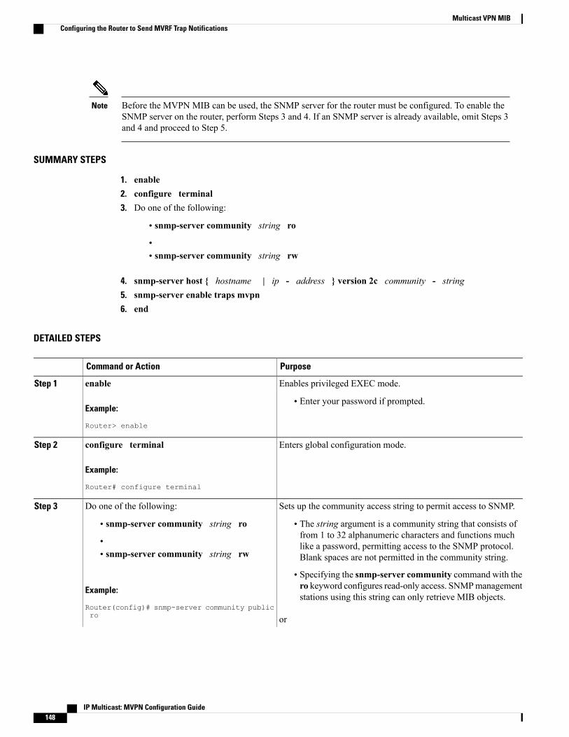
Before the MVPN MIB can be used, the SNMP server for the router must be configured. To enable theSNMP server on the router, perform Steps 3 and 4. If an SNMP server is already available, omit Steps 3and 4 and proceed to Step 5.
Note
SUMMARY STEPS
1. enable2. configure terminal3. Do one of the following:
• snmp-server community string ro
•• snmp-server community string rw
4. snmp-server host { hostname | ip - address } version 2c community - string5. snmp-server enable traps mvpn6. end
DETAILED STEPS
PurposeCommand or Action
Enables privileged EXEC mode.enableStep 1
Example:
Router> enable
• Enter your password if prompted.
Enters global configuration mode.configure terminal
Example:
Router# configure terminal
Step 2
Sets up the community access string to permit access to SNMP.Do one of the following:Step 3
• snmp-server community string ro • The string argument is a community string that consists offrom 1 to 32 alphanumeric characters and functions much• like a password, permitting access to the SNMP protocol.Blank spaces are not permitted in the community string.• snmp-server community string rw
• Specifying the snmp-server community command with thero keyword configures read-only access. SNMPmanagementstations using this string can only retrieve MIB objects.
Example:
Router(config)# snmp-server community publicro or
IP Multicast: MVPN Configuration Guide148
Multicast VPN MIBConfiguring the Router to Send MVRF Trap Notifications
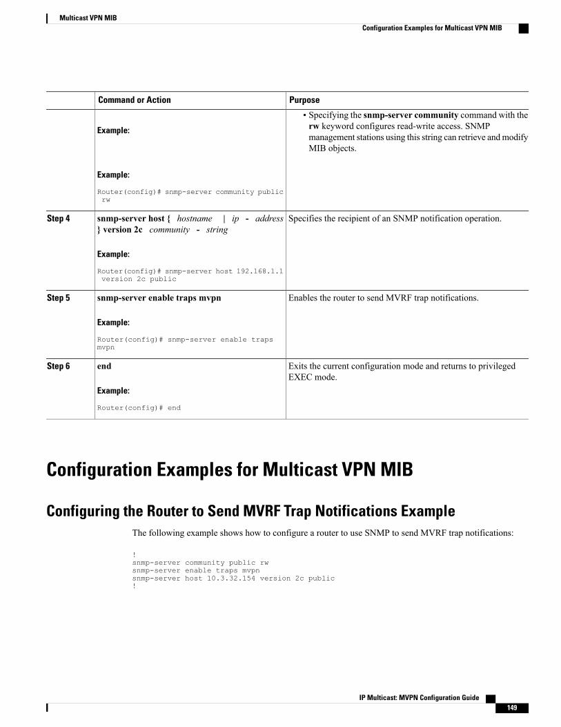
PurposeCommand or Action
Example:
• Specifying the snmp-server community command with therw keyword configures read-write access. SNMPmanagement stations using this string can retrieve andmodifyMIB objects.
Example:
Router(config)# snmp-server community publicrw
Specifies the recipient of an SNMP notification operation.snmp-server host { hostname | ip - address} version 2c community - string
Step 4
Example:
Router(config)# snmp-server host 192.168.1.1version 2c public
Enables the router to send MVRF trap notifications.snmp-server enable traps mvpn
Example:
Router(config)# snmp-server enable trapsmvpn
Step 5
Exits the current configuration mode and returns to privilegedEXEC mode.
end
Example:
Router(config)# end
Step 6
Configuration Examples for Multicast VPN MIB
Configuring the Router to Send MVRF Trap Notifications ExampleThe following example shows how to configure a router to use SNMP to send MVRF trap notifications:
!snmp-server community public rwsnmp-server enable traps mvpnsnmp-server host 10.3.32.154 version 2c public!
IP Multicast: MVPN Configuration Guide 149
Multicast VPN MIBConfiguration Examples for Multicast VPN MIB

Additional ReferencesRelated Documents
Document TitleRelated Topic
Cisco IOS IP Multicast Command ReferenceMVPN commands: complete command syntax,command mode, command history, defaults, usageguidelines, and examples
Cisco IOSNetworkManagement CommandReferenceSNMP commands: complete command syntax,command mode, command history, defaults, usageguidelines, and examples
Standards
TitleStandard
--No new or modified standards are supported by thisfeature.
MIBs
MIBs LinkMIB
To locate and downloadMIBs for selected platforms,Cisco IOS releases, and feature sets, use Cisco MIBLocator found at the following URL:
http://www.cisco.com/go/mibs
• CISCO-MVPN-MIB.my
RFCs
TitleRFC
--No new or modified RFCs are supported by thisfeature.
IP Multicast: MVPN Configuration Guide150
Multicast VPN MIBAdditional References
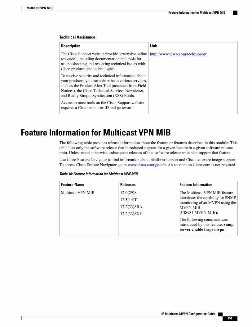
Technical Assistance
LinkDescription
http://www.cisco.com/techsupportThe Cisco Support website provides extensive onlineresources, including documentation and tools fortroubleshooting and resolving technical issues withCisco products and technologies.
To receive security and technical information aboutyour products, you can subscribe to various services,such as the Product Alert Tool (accessed from FieldNotices), the Cisco Technical Services Newsletter,and Really Simple Syndication (RSS) Feeds.
Access to most tools on the Cisco Support websiterequires a Cisco.com user ID and password.
Feature Information for Multicast VPN MIBThe following table provides release information about the feature or features described in this module. Thistable lists only the software release that introduced support for a given feature in a given software releasetrain. Unless noted otherwise, subsequent releases of that software release train also support that feature.
Use Cisco Feature Navigator to find information about platform support and Cisco software image support.To access Cisco Feature Navigator, go to www.cisco.com/go/cfn. An account on Cisco.com is not required.
Table 10: Feature Information for Multicast VPN MIB
Feature InformationReleasesFeature Name
The Multicast VPN MIB featureintroduces the capability for SNMPmonitoring of an MVPN using theMVPN MIB(CISCO-MVPN-MIB).
The following command wasintroduced by this feature: snmpserver enable traps mvpn
12.0(29)S
12.3(14)T
12.2(33)SRA
12.2(33)SXH
Multicast VPN MIB
IP Multicast: MVPN Configuration Guide 151
Multicast VPN MIBFeature Information for Multicast VPN MIB

IP Multicast: MVPN Configuration Guide152
Multicast VPN MIBFeature Information for Multicast VPN MIB