Embed Size (px)
Citation preview

Catalogue2010
Low voltage
NG160 16 to 160 AModular incoming circuit breakers and switch-disconnectors for DIN-panel installation

NG160 circuit breakerReady to install
�
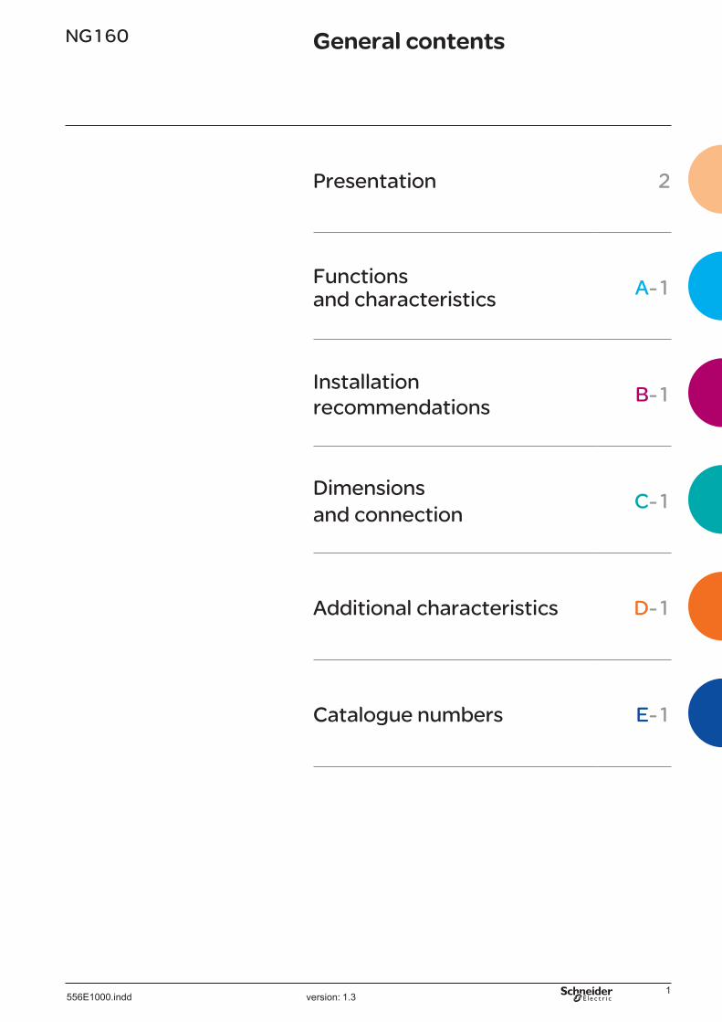
NG160 General contents
Presentation 2
Functions and characteristics A-1
Installation recommendations
B-1
Dimensions and connection
C-1
Additional characteristics D-1
Catalogue numbers E-1
version: �.3 556E�000.indd

�
NG160 circuit breakerIncomer for modular panels
Mounting on a DIN railThe NG�60 circuit breaker and its installation system were specially designed for the incomer function in modular switchboards.The result meets the need for a “ready to install” device offering high-quality mounting and wiring characteristics.
Vigi earth-leakage protection modulefor side-by-side mounting
Earth-leakage protection is widely used on the switchboard incomer function.
Mounting of a Vigi module alongside the incomer optimises enclosure space and leaves more room for other modular devices and instruments in the same row.
The new rigid cables for the Vigi module reduce connection errors and avoid tightening problems during mounting.
Presentation
version: �.3 556E�000.indd

3
45 mm cut-outsfor modular mounting plates
The NG�60 front escutcheon complies with the 45 mm standard.This means the NG�60 and Multi 9 switchgear can be mounted on the same DIN rail with all the fronts aligned.
New raisers for depth adjustersfor Multi 9
The raiser is used to fit an elevator DIN rail to compensate for the difference in depth between the NG�60 and Multi 9 devices. The new design ensures greater rigidity for the devices on the DIN rail.Electrical continuity between the two rails for earthing purposes is provided by a metal insert on the depth adjuster.
version: �.3 556E�000.indd

4
DIN mounting platealready on the device
The Compact NG�60 circuit breaker comes with its mounting plate already secured to the device.The NG�60 is “ready to install” right from its package.
Two-position clipfor fast mounting on a DIN rail
The circuit breaker and Vigi module mounting plates are equipped with two-position clips that can be opened and closed for easy mounting. Just open the clip with a screwdriver, place the NG�60 in the desired position and close the clip to secure the device to the DIN rail.
Built-in connectorsfor cables up to 70 mm2
The Compact NG�60 circuit breaker is supplied with its aluminium tunnel terminals.They are designed for both Cu and Al cables with stripped ends or ferrules.In this way, wiring is “ready to install”.
NG160 circuit breakerQuick installation!
version: �.3 556E�000.indd

5
New DIN railwith adjustable support
The new DIN rail support specially designed for incoming devices instantly adapts the DIN rail to the desired depth.The engraved depth indications ensure correct positioning of NG�60, NS�60 and NG��5 devices.The reinforced rigidity of the rail and its securing system ensure reliable mounting.
Distribution systemsfor connection to Powerclip busbars
The new distribution systems for Prisma Plus switchboards and enclosures were designed for fast and totally safe connection of NG�60 and NG��5 incoming devices and Interpact switch-disconnectors.One-piece prefabricated cable assemblies can be used for connection to the busbars and to Distribloc or Polybloc Multiclip distribution blocks to supply rows of Multi 9 breakers.The space under the rail is sufficient for the measurement CTs.
version: �.3 556E�000.indd

6
NG160 circuit breakerOperating safety
Breakingvia a double contact
To increase limiting of the fault current, each pole of the NG�60 circuit breaker has a double fork-shaped contact.This design splits the arc and significantly reduces the forces exerted during a short-circuit.This ensures the integrity of installations in enclosures.
Cascadingwith Multi 9 circuit breakers
Thanks to its very high current-limiting capacity, the NG160 offers excellent cascading and discrimination with downstream Multi 9 breakers.This means Multi 9 devices can have breaking performancies lower than the prospective short-circuit current, thus reducing their cost.
Vigi earth-leakage protection modulewith direct tripping
If a residual-current fault occurs, the Vigi module of the NG�60 acts directly on the tripping mechanism of the breaker via a mechanical link (no need to add a release coil).This solution avoids any risk of non-tripping due to poor connections.
version: �.3 556E�000.indd

�
Vigi earth-leakage protection module with rigid cablesfor optimum positioning in the toroid
The power cables are perfectly centred in the Vigi toroid to ensure precise measurement of the residual current and avoid risks of nuisance tripping.This solution ensures optimum continuity of service for the installation.
version: �.3 556E�000.indd

�
NG160 circuit breakerSuper-immunised protection
Earth-leakage protectionbased on "si" technology
The earth-leakage protection function is mandatory to protect life and property, but can be affected by disturbed environments, such as:> high-frequency currents with low rms values> voltage surges caused by atmospheric phenomena such as lightning> opening and closing of capacitive circuits.These disturbances often cause nuisance tripping of residual-current devices leading to installation down-time costs.Thanks to the "si" (super immunised) technology, the Vigi NG�60 guarantees operation of the earth-leakage protection only if there is a real risk.
Operating safetyin severe environments (to -25 °C)
Operation of the Vigi NG�60 is not affected by low temperatures down to -�5 °C.
version: �.3 556E�000.indd

9
Consistent designof the Schneider Electric low-voltage system
PragmaNew range of modular enclosures
The new range of Pragma enclosures combines functionality, robustness and attractive design, offering installers a complete solution for protection, control and distribution installations up to 960 A. They are available in flush-mount and surface-mount versions, with a capacity of �4 modules.Their are especially well-suited for installations in the commercial sector.
Prisma Plus GWall-mount and floor-standing enclosures up to 630 A
The Prisma Plus G range was designed for all types of wall-mount and floor-standing enclosures up to 630 A for commercial and small industrial applications.All the enclosure components, modular DIN-rail devices and installation and connection systems contribute to fast and easy construction of Prisma Plus G enclosures.
Prisma Plus PFunctional system up to 3200 A
Prisma Plus P high-power switchboards are the best solution for demanding installation and safety requirements.The perfect fit between the Prisma Plus P system, the low-voltage devices and the specially tested prefabricated connection solutions guarantees a safe and high-performance electrical installation.
version: �.3 556E�000.indd

�0 version: �.3 556E�000.indd

A-�
Functions and characteristicsNG160
Presentation 2
Characteristics of NG160 circuit breakers and switch-disconnectors 0 Incomer for modular switchboards A-�
Accessories for NG160 circuit breakers and switch-disconnectors 0 Incomer for modular switchboards A-3
Installationrecommendations B-1Dimensionsandconnection C-1Additionalcharacteristics D-1Cataloguenumbers E-1
version: 3.3 556E�000TDM.indd

A-�
3 and 4 pole circuit breakers and switch-disconnectors specially designed for use upstream of Multi 9 modular devices:b reinforcement of breaking capacities of downstream devices by cascading up to �5 kAb easy installation in Pragma or Prisma Plus type G enclosures:v standard 45 mm front cut-outv clip-on installation on a DIN railv reduced depth (��.5 mm).
NG160 circuit breakerElectrical characteristics as per IEC 60947-2
Rated current (A) In 40 °C �60Rated insulation voltage (V) Ui �00Rated impulse withstand voltage (kV)
Uimp �
Rated operational voltage (V) Ue AC 50/60 Hz 500Type of circuit breaker E N H
Ultimate breaking capacity Icu AC ��0/�40 V �5 40 50(kA rms) 50/60 3�0/4�5 V �6 �5 36
Hz 440 V �0 �6 ��500 V � �0 �5
Service breaking capacity Ics % Icu �5 %Suitability for isolation bDurability (C-O cycles) mechanical �0000
electrical (In -440 V) 5000
PB
�035
��-S
E-4
0
ProtectionBuilt-in thermal-magnetic trip unitRatings In �6 �5 3� 40 50 63 �0 �00 ��5 �60Thermal protection Ir fixed threshold
Magnetic protection lm 600 600 600 600 600 �00 �00 �000 ��50 ��50
NG160NA switch-disconnectorElectrical characteristics as per IEC 60947-3
Conventional thermal current (A) Ith 40 °C �60 Rated insulation voltage (V) Ui �00Rated impulse withstand voltage (kV)
Uimp �
Rated operational voltage (V) Ue AC 50/60 Hz 500Rated operational current Ie AC 50/60 Hz AC22A AC23A
��0/�40 V �60 �603�0/4�5 V �60 �60440/4�0 V �60 �60
PB
�035
30-S
E-5
�
500 V �60 ��5NG160circuitbreaker. Short-circuit
making capacitylcm (kA peak)
min. for switch-disconnector alone
�.�
max. with protection by upstream circuit breaker
330
Short-time withstand current Icw (A rms) � s �5003 s �500
Suitability for isolation b
Coordination between circuit breakers and switch-disconnectorsThe switch-disconnector must be protected against downstream short-circuits. The choice of the right switch-disconnector therefore depends on coordination with the protective device installed upstream. The table below indicates the maximum short-circuit current in kArms for which the switch-disconnector is protected by coordination with the circuit breaker located upstream.Important: the switch-disconnector must be protected against overloads. The rating of the switch-disconnector must be greater than or equal to that of the upstream circuit breaker.
Upstream protection NR100F NS100 - NS160NR160F N SX H
NG160NA downstream3�0 - 4�5 V
Isc max kA rms �5 36 50 �0Making capacity kA peak 5� �5 �05 �54
440 V
Isc max kA rms �0 35 50 65Making capacity kA peak 4� �3 �05 �43
Installation and connectionsConnections
Connectors Bare cables from �.5 to �0 mm² cablesDimensions (mm) W x H x D Width in
9 mm modulesNG�60 3P 90 x 120 x 82.5 �0
4P 120 x 120 x 82.5 �4NG�60 with Vigi
3P 210 x 120 x 82.5 �44P 240 x 120 x 82.5 ��
Weight (kg)Device 3P �.�
4P �.4Device + Vigi module
3P �.64P �.9
NG160inmodularenclosure.
Functions and characteristics Characteristics of NG160 circuit breakers and switch-disconnectors 0 Incomer for modular switchboards
version: 5.3 556E�000.indd

A-3
PB
�035
��-S
E-5
�
Earth-leakage protection : add-on Vigi moduleCan be installed on the right side of the circuit breaker or switch-disconnector. Two versions allow connection of outgoing circuits to the top or bottom of the Vigi module to meet installation requirements.
Characteristics as per IEC/EN 60947-2 annex BNumber of poles 3, 4Sensitivity (A) 0.03 / 0.3 / � / 3Time delay intentional (1) (ms) 0 60 �50
max. break time < 40 < �40 < �50Rated voltage (V) 50/60 Hz �00 to 440 VReset pushbuttonTest pushbutton
NG160 +add-onVigimodule. Protection against nuisance tripping bDC-component withstand class A
PB
�0�6
93_S
E_5
0
(1) Ifthesensitivityissetto30mA,thereisnotimedelay,whateverthetime-delaysetting.
Prefabricated incoming connections to Vigi module for top or bottom outgoing connections
DB
��6�
40
Out
In
DB
��6�
4�
In Out
PB
�0�6
9�_S
E_5
0
Accessories for NG160 circuit breakers and switch-disconnectors 0 Incomer for modular switchboards
version: 5.3 556E�000.indd

A-4
Functions and characteristicsD
B��
5��3
pushto
trip
NG160E
Ui 750 VUimp 8 kV
Icu 380/415 V16 kA
Ue (V)Icu (kA)
220/24025
380/41516
440
10
Ics = 75% Icu
50/60 Hzcat A
IEC / EN 60947-2
AS UNE CEI BS UTE VDE NEMA
NSØ5...Ø8
13/64...5/16
ONI
tripped
reset
OOFF
∅5...8
Auxiliary contactsOF and SD
Voltagereleases
Terminal shield
Din rail andraiser
Toggle locking
Rotaryhandles
Distributionconnectors
Terminal shield
Auxiliaries and accessoriesAvailable auxiliaries include:
� ON/OFF indication contact (OF)� trip-indication contact (SD)� voltage release (MN undervoltage release or MX shunt trip)1 extended rotary handle with door locking, allowing operation of the device from
outside the enclosure.Depth adjusterThis accessory is required to align the front of Multi 9 devices when they are. installed next to a NG160. Maximum length 342 mm (36 modules).
Extended rotary handleDegree of protection: IP55, IK0�.This handle makes it possible to operate circuit breakers installed inside switchboards, from the switchboard front.It maintains:
suitability for isolationindication of the three positions O (OFF), I (ON) and trippedaccess to trip unit settings, when the switchboard door is opencircuit breaker locking capability in the OFF position by one to three padlocks,
shackle diameter 5 to � mm (not supplied).The door cannot be opened if the circuit breaker is ON or locked.The extended rotary handle is made up of:
a unit that replaces the front cover of the circuit breaker (secured by screws)an assembly (handle and front plate) on the door that is always secured in the
same position, whether the circuit breaker is installed vertically or horizontallyan extension shaft that must be adjusted to the distance between the back of the
circuit breaker and the door, between a minimum of 185 mm and a maximum of 600 mm.
bbbb
bbbb
bb
b
NG160.
PB
�035
��-S
E-4
0
Toggle locking using a removable deviceThe circuit breaker can be locked in OFF position by fitting a removable accessory on the toggle. This locking system complies with the isolation requirements of IEC 6094�-�.One to three padlocks can be used, with shackle diameters from 5 to � mm.
Lockingaccessory.
Accessories for NG160 circuit breakers and switch-disconnectors 0 Incomer for modular switchboards
version: 5.3 556E�000.indd

A-5
PB
�0�6
96_�
3
Electrical auxiliariesOF contact (open/closed): indicates the position of the circuit breaker contactsSD contact (trip indication) indicates that the circuit breaker has tripped due to:an overloada short-circuitan earth faultoperation of an MX or MN voltage release.
The SD contact returns to de-energised state when the circuit breaker is reset.
bbvvvv
Indicationcontacts.Standard contacts
Rated thermal current (A) 6Utilisation category (IEC 6094�-5-�) AC�� AC�5Operational current (A) ��0/�40 V 6 4
3�0/440 V 6 �
PB
�0�6
9�_�
3
MX shunt release.Trips the circuit breaker when the control voltage rises above 0.� times the rated voltage.Control signals can be of the impulse type (u �0 ms) or maintained.
MN undervoltage releaseThis release trips the circuit breaker when the control voltage drops below a tripping threshold:
tripping threshold between 0.35 and 0.� times the rated voltagecircuit breaker closing is possible only if the voltage exceeds 0.85 times the rated
voltage.A time delay unit for the MN release eliminates the risk of nuisance tripping due to a transient voltage dip lasting y �00 ms. OperationWhen the circuit breaker has been tripped by an MN or MX release, it must be reset locally.MN or MX tripping takes priority over manual closing.In the presence of a standing trip order, closing of the contacts, even momentarily, is not possible.
b
b
vv
MXorMNvoltagerelease.
Remote trippingCharacteristics MN MX
Power supplyV AC 50/60 Hz �4 V, 4� V, ��0/�30 V, ��0/�40 V, 3�0/4�5 V, 440/4�0 VV DC �4 V, 4� V, ��0-��5 V, �50 V
Operating threshold 0.�5 to �.� Un 0.� to �.� UnConsumption (pick-up/hold) < 5 VA < 5 VAResponse time < 50 ms < 50 msConnection cable diameter 1.5 mm² max 1.5 mm² max
Wiring diagram
DB
��46
95
12 14
OF
11
92 94
SD
91
C1
C2
MX
D1
D2
MN (1)Trip unit
(1) MNorMX(MN:D1,D2;MX:C1,C2).
version: 5.3 556E�000.indd

A-6version: 5.3 556E�000.indd

B-�
Installation recommendationsNG160
Presentation 2Functionsandcharacteristics A-1
NG160 connection and installation in switchboards 0 B-3
Modular devices Installation in Prisma Plus wall-mountand floor-standing enclosures B-4
Dimensionsandconnection C-1Additionalcharacteristics D-1Cataloguenumbers E-1
version: �.� 556E��00TDM.indd

B-�version: �.� 556E��00TDM.indd

B-3
Installation recommendations
DB
��46
9�
DB
�0��
55
ConnectionsNG�60 devices come with built-in bare-cable connectors as standard.They can be tightened with a 4 mm male spanner.The distribution lug can be used to connect 3 small-size cables.
Standard device With distribution lug
E54
545
Rating (A) �6 to ��5 �60 �6 to �60L (mm) �� y �0S (mm²) rigid �.5 to �0 �0 to �0 �.5 to �6 Cu / Al flexible �.5 to 50 �0 to 50 � to �0 (1)
Tightening torque (Nm)
5.6 �.5 �
(1)Flexiblecablesfrom1.5to4mm²:connectionwithcrimpedorself-crimpingferrules.
Connectionbycables. Distributionlugfor3cables.
DB
��46
9�
A1 Safety clearanceWhen installing a circuit breaker, minimum distances (safety clearances) must be maintained between the device and panels, bars and other protection devices installed nearby. These distances, which depend on the ultimate breaking capacity, are defined by tests carried out in accordance with standard IEC 60947-2.
NG160 Dimensions (mm)Voltage Insulation, insulated
bars or painted sheetmetal
Bare sheetmetal
Bare or painted sheetmetal ;insulation or insulated bars
D1
D2 C1
B
Frontpanel
F (1) C1 D1 D2 C1 D1 D2 A1 B
DB
��6�
43
DB
��6�
44
U y 440 V 0 30 30 5 35 35 �0 0 (2) 0(2) ForNG160withterminalshieldmounted.ThemandatorydistanceswheninstallingNG160circuitbreakersarecalculatedfromthedevicecase,nottakingintoaccounttheterminalshields.
Temperature deratingWhen the ambient temperature is greater than 40 °C, overload-protection characteristics are slightly modified. To determine tripping times using time/current curves, use Ir values corresponding to the thermal setting on the device, corrected for the ambient temperature (see tables below).
NG160(1) IfF<8mm:insulatingscreenismandatory.Minimumdistancebetweenthecircuitbreakerandtopbottomorsidepanelsandfrontorrearpanels.
Rating (A) 40 °C 45 °C 50 °C 55 °C 60 °C 65 °C 70 °C�6 �6 �5.6 �5.� �4.� �4.5 �4 �3.��5 �5 �4.5 �4 �3.5 �3 �� ��3� 3� 3�.3 30.5 30 �9.5 �9 ��.540 40 39 3� 3� 36 35 3450 50 49 4� 4� 46 45 4463 63 6� 60 5� 56 54 5��0 �0 �� �� �5 �3 �� �0�00 �00 9� 96 93 9� �9 �6��5 ��5 ��3 ��0 ��� ��6 ��3 ����60 �60 �5� �53 �50 �46 �4� �39NG�60NA �60 �60 �56 �53 �46 �43 �40
Power dissipation (in Watts)Fixed circuit breaker Additional power
3/4 poles Rating (A)
P/pole Vigi(N, L3)
Vigi(L1, L2)
NG�60 �6 4 0.06 0.06�5 5 0.�6 0.�63� 5.5 0.�6 0.�640 6 0.4 0.450 � 0.63 0.6363 � � ��0 9 �.6 �.6�00 �0 �.5 �.5��5 ��.5 3.9 3.9�60 �5.4 6.4 6.4
NG�60NA �60 �5.4
NG160 connection and installation in switchboards
version: �.� 556E��00.indd

B-4
Modular devicesInstallation in Prisma Plus wall-mount and floor-standing enclosures
NG160 circuit breaker
DB
��4�
��
Device No.ofverticalmodules
Adjustablemodularrail(1)
Modularfrontplate
NG125 circuit breakerNG�60, Vigi NG�60 5 03002 + 04227 03205(1)Toaddmodulardevicestotherow,orderaraisedDINrail(04227).Capacity of modular rail: 4� Multi 9 modules.WidthofNG160circuitbreakers: NG1603P:10Multi9modules NG1604P:14Multi9modules VigiNG1603P:24Multi9modules VigiNG1604P:27Multi9modules
NG125, C120 circuit breaker
DB
��4�
��
Device No.ofverticalmodules
Adjustablemodularrail
Modularfrontplate
Disjoncteur NG125NG��5, Vigi NG��5C��0, Vigi C��0
5 03002 03205
Capacity of modular rail: 4� Multi 9 modules.WidthofNG125circuitbreakers:NG1253P:9Multi9modules NG1254P:12Multi9modules VigiNG1253Py 63 A: fixed sensitivity 18 Multi 9 modules adjustablesensitivity20Multi9modules > 63 A: fixed sensitivity 20 Multi 9 modules adjustablesensitivity20Multi9modules VigiNG1254Py 63 A: fixed sensitivity 21 Multi 9 modules adjustablesensitivity23Multi9modules > 63 A: fixed sensitivity 23 Multi 9 modules adjustablesensitivity23Multi9modules
INS40/160 switch-disconnector
DB
��4�
��
Device No.ofverticalmodules
Adjustablemodularrail
Modularfrontplate
Hingedmodularfrontplate
INS40/160INS40/�60 4 03002 03204 03211INS�00/�60with long terminal shields
5 03002 03205
Capacity of modular rail: 4� Multi 9 modules.Widthofdevices: INS40/80:width10Multi9modules INS100/160:width15Multi9modules
125 A Powerclip busbars Available in two lengths (450 and �50 mm) in three and four-pole versions.The busbars can be cut to length every �50 mm.They are supplied with clip-on covers that block off the connected cable lugs and can be cut as needed.Cat. no. selectionD
B��
4��3
125 A Powerclip busbars Cat. no.Three-pole L = 450 mm 04103
L = �50 mm 04107Four-pole L = 450 mm 04104
L = �50 mm 04108
160/630 A Powerclip busbars Available in two lengths (�000 and �400 mm) in three and four-pole versions. The busbars can be cut to length every �00 mm.Prefabricated connections are available for the devices.Powerclip busbars 160 A 250 A 400 A 630 A
Three-pole L = �000 mm 04111 04112 04113 04114L = �400 mm 04116 04117 04118 04119
Four-pole L = �000 mm 04121 04122 04123 04124L = �400 mm 04126 04127 04128 04129
Installation recommendations
version: �.� 556E��00.indd

B-5
Busbar connection to powerclip NG160 Vigi incoming device (located on left-hand side) NG160 (without Vigi) incoming device (located in the middle) NG125, INS160, C120One-piece 3/4 P fast connection to busbars, equipped with male fittings on one end for tunnel terminals.3 black cables and � blue cable (reversible neutral position).
DB
��4�
�4
Designation Cat. no.One-piece connection, �60 A, L = 440 mm 04148
DB
��4�
�5
160 A Polybloc distribution block 160 A distribution block
DB
��4�
�6
Designation Cat. no.�60 A Polybloc distribution block, �P 04031Note: installationonaraisedDINrail.
Connection for NG125, NG160, INS40/160 with or without VigiTwo 45 mm² end fittings for tunnel terminals.Designation Cat. no.
Four �60 A connections for modular devices, L = 3�0 mm 04149
125/160 A Distribloc distribution block
125 A distribution block
DB
��4�
��
Designation Cat. no.��5 A Distribloc distribution block 04045Note: installationonaraisedDINrail.
Connection for NG125, INS40/160, C120 with or without VigiA male ferrule for a tunnel terminal is crimped on one end.A 45° angle lug with a hole is crimped on the other end.3 black cables and � blue cableDesignation Cat. no.
4 NG-INS��5 connections for Distribloc, L = ��0 mm 04047
160 A distribution blockDesignation Cat. no.
�60 A Distribloc distribution block 04046Note: installationonaraisedDINrail.
Connection for NG160, INS100/160 with or without VigiThe Distribloc �60 A distribution block comes with device connections.
Multiclip distribution blocks Distribution block
DB
��4�
��
Designation Cat. no.Multiclip, �0 A, 4P 04004Multiclip, 63 A, 4P, �/� row 04008Multiclip, �00 A, �P 04012Multiclip, �00 A, 3P 04013Multiclip, �00 A, 4P 04014Multiclip, �60 A, 4P, �/� row 04018
ConnectionsDesignation Cat. no.
Connection between �00 A Multiclip and Powerclip insulated busbars 04021Connection between �60 A Multiclip (�/� row) and devices 04030
version: �.� 556E��00.indd

B-6version: �.� 556E��00.indd

C-�
Dimensions and connectionNG160
Presentation 2Functionsandcharacteristics A-1Installationrecommendations B-1
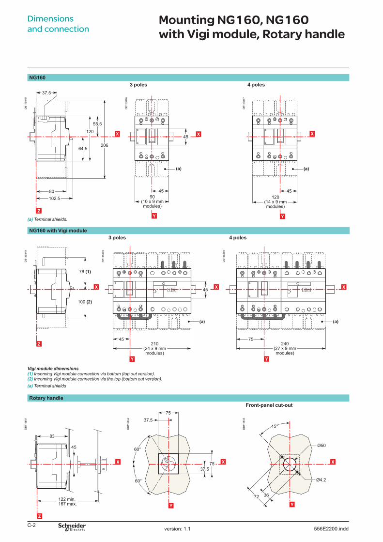
Mounting NG160, NG160 with Vigi module, Rotary handle 0 C-2
Additionalcharacteristics D-1Cataloguenumbers E-1
version: �.� 556E��00TDM.indd
C-�
Dimensions and connection
NG1603 poles 4 poles
DB
��6�
45
64.5
120
55.5
206
80102.5
37.5
X
Z
DB
��6�
46
45
4590
(10 x 9 mmmodules)
(a)
X
Y
DB
��6�
4�
45
(a)
120(14 x 9 mmmodules)
Y
X
(a)Terminalshields.
NG160 with Vigi module3 poles 4 poles
DB
��6�
4�
100 (2)
76 (1)
X
Z
DB
��6�
49
45
45210
(24 x 9 mmmodules)
(a)
X
Y
DB
��6�
50
240(27 x 9 mmmodules)
75
(a)
X
Y
Vigi module dimensions(1) IncomingVigimoduleconnectionviabottom(topoutversion).(2) IncomingVigimoduleconnectionviathetop(bottomoutversion).(a)Terminalshields
Rotary handleFront-panel cut-out
DB
��6�
5�
45
122 min.167 max.
83
X
Z
DB
��6�
5�
75
75
37.5
37.5
60°
60°
X
Y
DB
��6�
53
45°
3672
Ø50
Ø4.2
X
Y
Mounting NG160, NG160 with Vigi module, Rotary handle
version: �.� 556E��00.indd

D-�
Additional characteristicsNG160
Presentation 2Functionsandcharacteristics A-1Installationrecommendations B-1Dimensionsandconnection C-1
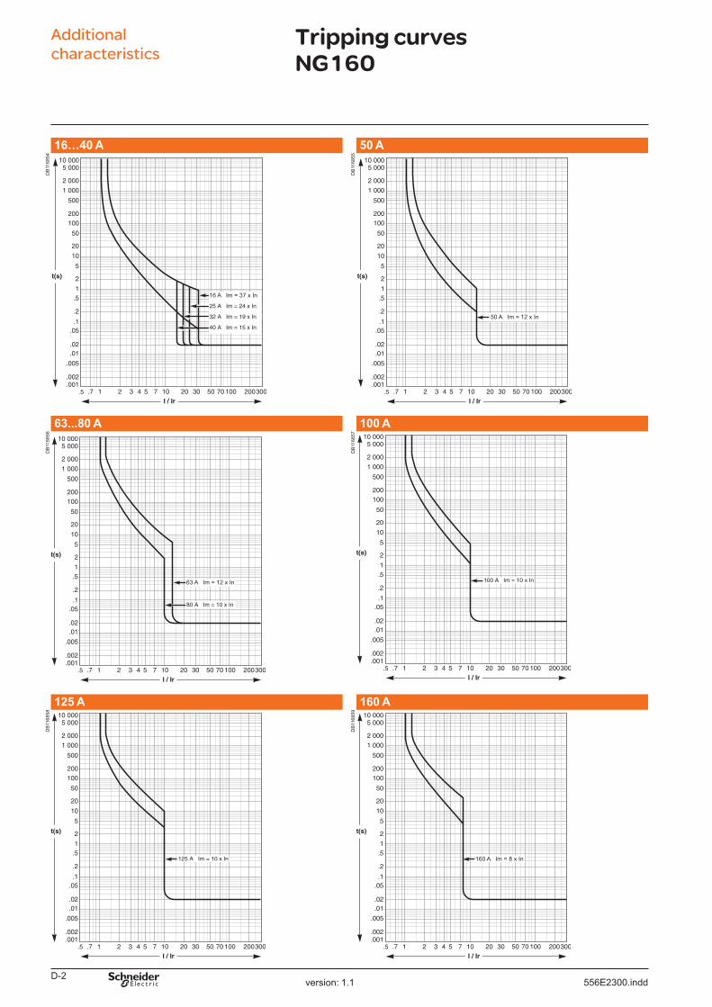
Tripping curves NG160 0 D-2
Cataloguenumbers E-1
version: �.� 556E�300TDM.indd
D-�
16…40 A 50 A
DB
��6�
54
DB
��6�
55
63...80 A 100 A
DB
��6�
56
63 A Im = 12 x In
DB
��6�
5�
125 A 160 A
DB
��6�
5�
DB
��6�
59
160 A Im = 8 x In
16 A Im = 37 x In16 A Im = 37 x In
50 A Im = 12 x In50 A Im = 12 x In
Tripping curves NG160
Additional characteristics
version: �.� 556E�300.indd

E-�
Catalogue numbersNG160
Presentation 2Functionsandcharacteristics A-1Installationrecommendations B-1Dimensionsandconnection C-1Additionalcharacteristics D-1
NG160E/N/H circuit breakers NG160NA switch-disconnectors 0 E-2
NG160E/N/H and NG160NA accessories 0 E-3
version: �.� 556E5000TDM.indd

E-�
Catalogue numbers
NG160E
DB
��4�
�0
NG160E (16 kA at 380/415 V)Rating 3P (10 x 9 mm modules) 4P (14 x 9 mm modules)
Fixed �6 28609 28619�5 28608 286183� 28607 2861740 28606 2861650 28605 2861563 28604 28614�0 28603 28613�00 28602 28612��5 28601 28611�60 28600 28610
NG160N
DB
��4�
�0
NG160N (25 kA at 380/415 V)Rating 3P (10 x 9 mm modules) 4P (14 x 9 mm modules)
Fixed �6 28629 28639�5 28628 286383� 28627 2863740 28626 2863650 28625 2863563 28624 28634�0 28623 28633�00 28622 28632��5 28621 28631�60 28620 28630
NG160H
DB
��4�
�0
NG160H (36 kA at 380/415 V)Rating 3P (10 x 9 mm modules) 4P (14 x 9 mm modules)
Fixed �6 28649 28659�5 28648 286583� 28647 2865740 28646 2865650 28645 2865563 28644 28654�0 28643 28653�00 28642 28652��5 28641 28651�60 28640 28650
NG160NA switch-disconnectorsRating 3P (10 x 9 mm modules) 4P (14 x 9 mm modules)�60 28265 28267
Add-on Vigi moduleBottom out
Rating Sensitivity Delay 3P (14 x 9 mm modules) 4P (14 x 9 mm modules)
DB
�0�5
�3
�60 Adjustable30 mA at 3 A
Adjustable 0 - 60 - �50 ms
28310 28311
DB
��6�
60
Top outRating Sensitivity Delay 3P (14 x 9 mm modules) 4P (14 x 9 mm modules)
DB
�0�5
�4
�60 Adjustable30 mA at 3 A
Adjustable 0 - 60 - �50 ms
28312 28313
DB
��6�
6�
NG160E/N/H circuit breakers NG160NA switch-disconnectors 0
version: 6.3 556E5�00.indd

E-3
Connection accessoriesTerminal shields (1 pair) for Vigi circuit breaker
DB
�0�5
�5
3P 280344P 28035
Distribution connectors
DB
�0�6
�6
3 x 16 mm� Set of 4 19091
Mounting accessories
DB
�0�6
��
Din rail and 4 raisers for Multi 9 devices, length 34� mmFor �4 module enclosure 04227 (1)
For 36 module enclosure 2 x 04227 (1)
LockingToggle locking device for 1 or 3 padlocks
DB
�0�5
��
29370
Electrical auxiliariesAuxiliary contacts (changeover)
DB
�0�6
�0
OF or SD 29450OF or SD low level 29452
Voltage releases
DB
�0�5
�6
AC 50/60 Hz Tension (V) MX MN4� 28070 28080��0/�30 28071 28081��0/�40 28072 280823�0/4�5 28073 28083440/4�0 28074 28084
MN ��0-�40 V 50/60 Hz with time delay composed of:
29421MN �50 V DC 28088Delay unit ��0-�40 V 50/60 Hz 29427
DC Voltage (V) MX MN�4 28075 280854� 28076 28086��5 28077 28087�50 28078 28088
Rotary handles
DB
�0�5
��
Black extended handle 28061Red extended handle on yellow front 28060
(1) MGAparts.
NSØ5...Ø8
13/64...5/16NSØ5...Ø8
13/64...5/16
NG160E/N/H and NG160NA accessories 0
version: 6.3 556E5�00.indd


Schneider Electric Industries SAS35, rue Joseph MonierCS 30323F- 92506 Rueil Malmaison Cedex
RCS Nanterre 954 503 439Capital social 896 313 776 €www.schneider-electric.com
10-2009556E
© 2
009
- Sch
neid
er E
lect
ric -
All
right
s re
serv
ed.
As standards, specifications and designs change from time to time, please ask for confirmation of the information given in this publication.
This document has been printed on ecological paper
Design: Schneider ElectricPhotos: Schneider ElectricPrinted:
0