Embed Size (px)
Citation preview
G . • 61 cot • Se rn.
-hAney¼ C-0A. cAA ea • Bharatiya Vidya Bhavan's.
Sardar Patel College of Engineering (Govt. Aided Autonomous Institute Affiliated to University of Mumbai)
End Semester Examination November 2015 Subject: Numeaes Date: November 28, 2015. Class: S. Y. B. Tech. (Electrical, Sem: IIIL Total Marks: 100
Note: 1. Solve any FIVE questions of the following. Al! questions carry equal marks.
2. Group the answers to all sub-questions together. Thets-Fe,r f e •
1. a.
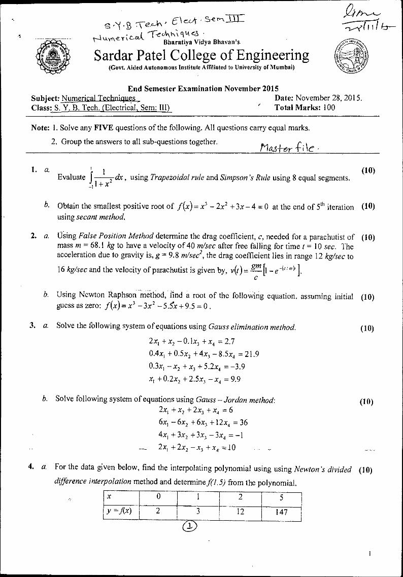
i (10) Evaluate 5 dx , using Trapezoidal rule and Simpson 's Rule using 8 equal segments.
1+ x2
b. Obtain the smallest positive root of f (x)= x 3 — 2x2 +3x —4 = 0 at the end of 5th iteration (H) using secant method.
2. a. ()Sing False Position Method determine the drag coefficient, c, needed for a parachutist of (10) mass in = 68.1 kg to have a velocity of 40 m/sec after free falling for time I = 10 sec. The acceleration due to gravity is, g= 9.8 m/sec 2, the drag coefficient lies in range 12 kg/sec to
16 kg/sec and the velocity of parachutist is given by, v(t)-= ff-L-n [1— e -('''" )11,
b. Using Newton Raphson method, find a root of the following equation, assuming initial (10) guess as zero: f (x)= x' —3x 2 — 5.5.X + 9.5 = 0 .
3. a. Solve the following system of equations using Gauss elimination method. (10)
2x1 +x2 —0.1x3 +x4 = 2.7
0.4x, +0.5x2 +4x3 —8.5; = 21.9
0.3x1 —x2 +x3 5.2; =-3.9
x, + 0.2x2 + 2.5x3 — x„ =- 9.9
b. Solve following system of equations using Gauss — Jordan method: (10) 2x 1 + x2 + + x, = 6
6x1 —6x2 +6; +12; =36
4x1 ±3x2 +3x6 —3; =-1
2x, + 2x2 —x, + =10
4. a. For the data given below, find the interpolating polynomial using using Newton's divided (10) difference interpolation method and determine f(1.5) from the polynomial.
Ix 1 0 1 1 2 1
5 I ! y =flx)
1
I 2 3 1
I 12 1
! 147 I
I 0

0 1
2
y=1(x) 1 1.8 I 1.3
3
2.5 1 4
2.3
s .•( • B :Tea. E I evi- • Se&t-ILL t4LA n\ e•A'c4 Te_cit-o-deit-tes - 2I 1C
h. An experiment carried out gave the temperature readings at time t, as follows: (10)
Time (Sec) 0 1 1 I 2 3 . 4 1 5 6 I 7 1 8 1
1 Temperature (0q
1
1
60.00 I 64.50 I 72.50 1 80.00
• 1
86.25 I 92.50 1 105.00 111.00 118.25 1
Using this data, obtain the temperature at time 3.5 sec and time at temperature 100 °C.
5. a. Find the parabola of degree for the data given below using least squares approximation (10) method:
b. Using Newton's Forward or Backward differences Interpolation method, find the cubic (10) polynomial governing the data given below and determine,f(4) from it.
x 0 1 1 2 3
y=f(x) f
1 01 11 10
6. a. Use Euler 's Predictor-Corrector method to solve 10-#- = x 2 + y 2 for 0.5 x 1.0,
dx assuming x, = 0, yo = 0 and h = 0.5.
b. Using 4th order Runge Kutta method, solve the following equations at x = 0.2, d2y x dy y dx2 dx •
Assume step size of 0.2 and initial approximations of yo=1 and —dy
= 0 at x0=0. cbc
7. a. From the data given below, find the value of x for which f(x) is maximum and also find (10) maximum value off(x).
1 1.2 1.3 I 1.4 1.5 1 1.6
Y=./(x) I 0.9320 1 0.9636 i I
I 0.9855 0.9975 0.9996
b. Explain the golden section search method for minimization. (05) Discuss how optima are calculated. (05)
2
(10)
(10)
S • '•( • '3 • 're cA- Liackncj. r11 I
6 eckrcôA 1,\ c-{Au crdcs- Sardar Patel College of Engineering
Bharatiya Vidya Bhavan's (A Government Aided Autonomous Institute)
Munshi Nagar, Andheri (West), Mumbai - 400058. End Semester Exam
November 2015
Max. Marks: 100 Class: S.Y.BTech Semester: III
Name of the Course: Electrical Networks Instructions: 1. Question No 1 is compulsory. 2. Attempt any four questions out of remaining six. 3. In the absence of any data, make suitable assumptions and justify the same
4. Figures to the right indicate full marks.
Question No.
Max. Marks
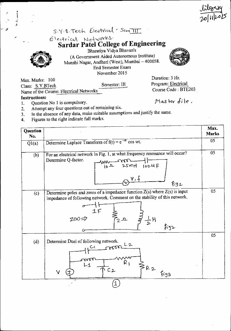
Ql(a) Determine Laplace Transform of f(t) = e -at cos wt. 05
(b) For an electrical network in Determine Q-factor.
Fig. 1, at what frequency resonance will occur? 05
I b -5)- ')..„s rnti loom F
-c a (c) (c) Determine poles
impedance of and zeros of a impedance function Z(s) where Z(s) is input
following network. Comment on the stability of this network.
o----A ir
.2_ -
05
(d) Determine Duel
V
of following network. L 2
05 05
•c 2_.
fl‘ 3
Duration: 3 Hr. Program: Electrical Course Code : BTE203
Picts ey Si I e ,

ftE)
®
G E eLtritc4
CCAM;"at t.0 - (Leh I C Q2 (a)
, . Determine Z parameters of following network. 10
Y9.- F clAiv\AII\, ..
---{
II
WAAr-------o
li3
(b) For the given network, draw oriented graph. Select a tree and write tie-set and cut- 10
set matrix al a 2-
R3 1-1
c
PC P-5 414 P. if
Q3 (a) Find the value of load impedance that allows maximum power transfer to the load. Calculate maximum power transferred to the load.
10
O to.)- 0
12-52- ,
6 cli Bo J2— 1111 1-
(b) Evaluate node voltages VI, V2, V3 and V4• 10
4
0 III A
i3 eS' .1Q-V C
1/ oe
f5I \IJi Q4 (a) Determine complex frequency and current i(t) using complex frequency analysis.
The network is excited by a voltage source v(t) = 10 e -4 cos 2t. 10
P-9 9-

S.•(43-7Ted, S:--(tokiej_Sevrthl tlJrIf
(b) — ,
For a given electrical network determine R1, R2 and C if voltage transfer function 10
— d- RI H (s) = 11 vi(s) 52+3 s+2 • , • . 0,4
\S) c
a
Vo
a
+ 9 5
Q5 (a) In a RLC circuit shown below, capacitor is initially charged to Vo = 200 V. Find the current i(t) after the switch is closed at t=0.
10
T-----Cyr; b s d.. H
0 --t- ts.c_ -
I-1310
-V 0
(b) Derive the expression for current and voltage across a capacitor and plot current and voltage as a function of time. Derive the expression for time constant.
10
Q6 (a) Obtain currents i l and i2 fort 0 if switch is closed at t=0.
- *
10
kt3OV
-t- .7-- o 10 -51-
-
1 L a 5,52- 5_52-
0.01H
1 (b) Determine current supplied by the source using Laplace Transform if vs(t) = 10 u(t).
10
.%%, vs(fA 0
1 A-I p
Q7 (a) s2 +4 s+3 14 Realize the foster and Caur forms of impedance function Z(S) = s2+2s
(b) s2+1. is function.
06 Test whether (s) r-- -i--- a positive real
s +4 s

6 V
3.3V
tabzif)-4-0
18100-el C
S Sevn-.1/1-
EI c/A-roY.i C_ C; Y-0-ti-I-s • rat - IS III - Bharatiya Vidya Bhavan's
Sardar Patel College of Engineerinf (A Government Aided Autonomous Institute)
Munshi Nagar, Andheri (West), Mumbai —400058. End Semester Exam
November 2015 Max. Marks: Duration: 3 hours
Class: S.Y. B. Tech Semester: III Program: Electrical Engineering Name of the Course: Electronic Circuits Course Code : BTE202 Instructions: M cks-\-ey le - I. Question No 1 is compulsory. 2. Attempt any four questions out of remaining six. 3. Draw neat diagrams 4. Assume suitable data if necessary
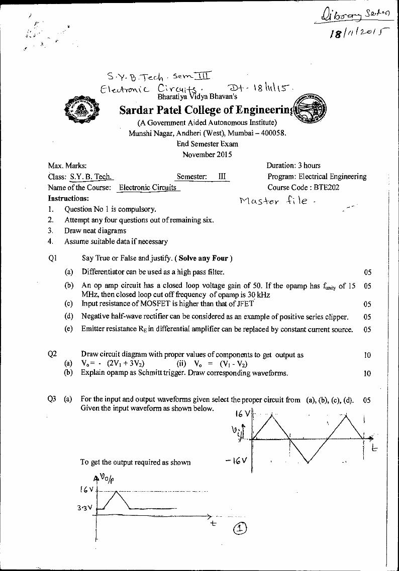
Q1 Say True or False and justify. ( Solve any Four)
(a) Differentiator can be used as a high pass filter. 05
(b) An op amp circuit has a closed loop voltage gain of 50. If the opamp has fi„„ty of 15 05 MHz, then closed loop cut off frequency of opamp is 39 kHz
(c) Input resistance of MOSFET is higher than that ofJFET 05
(d) Negative half-wave rectifier can be considered as an example of positive series clipper. 05
(e) Emitter resistance RE in differential amplifier can be replaced by constant current source. 05
Q2 Draw circuit diagram with proper values of components to get output as 10 (a) V° - (2V1 + 3V2) (ii) Vo = (V1 - Y2) (b) Explain opamp as Schmitt trigger. Draw corresponding waveforms. 10
Q3 (a) For the input and output waveforms given select the proper circuit from (a), (b), (c), (d). 05 Given the input waveform as shown below.
16 V
AA..
To get the output required as shown — 16 V
•
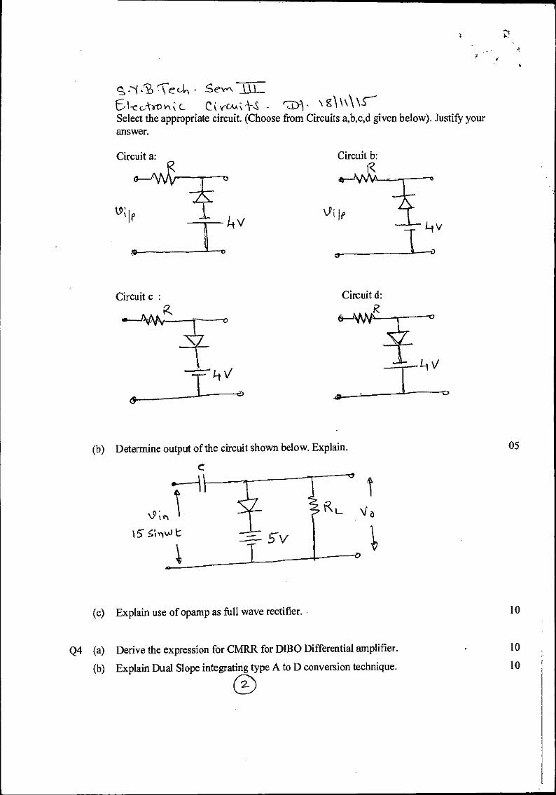
it?) rce Se'vnTjiL 61-ccAroln c- Cir(ma-S - • \ g\ \\\ Select the appropriate circuit. (Choose from Circuits a,b,c,d given below). Justify your answer.
Circuit a:
Circuit c :
(b) Determine output of the circuit shown below. Explain. 05
(c) Explain use of opamp as full wave rectifier. 10
Q4 (a) Derive the expression for CMRR for DIBO Differential amplifier. 10
(b) Explain Dual Slope integrating type A to D conversion technique. 10
Ltic
'"V
V
1-Dss= 8 "I A v v
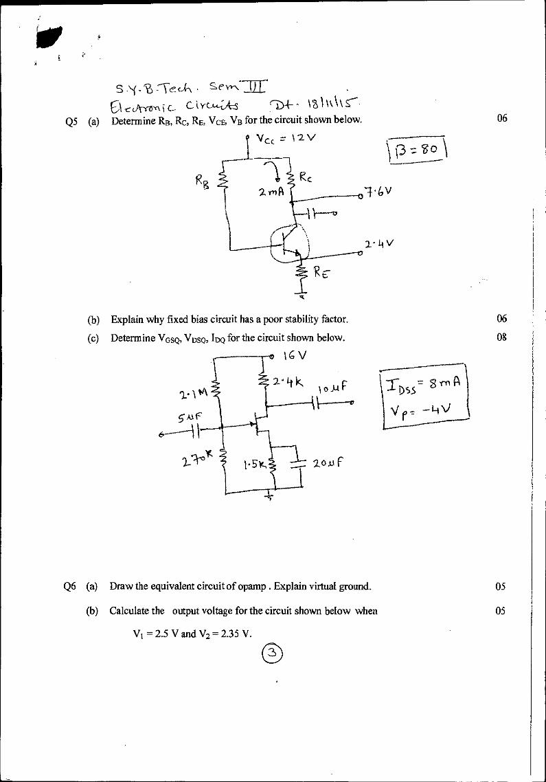
Explain why fixed bias circuit has a poor stability factor.
Determine VGSQ, VDsQ, IDQ for the circuit shown below.
16 V
zo.ur
06
08
S •(-T):Tec,k sevr\ () cutro-,1 c_ C Yti"-;1e
Q5 (a) (a) Determine RB, Itc, RE, VCE, VB for the circuit shown below. 06
Q6 (a) Draw the equivalent circuit of opamp . Explain virtual ground. 05
(b) Calculate the output voltage for the circuit shown below when
05
= 2.5 V and V2 = 2.35 V.
5.`f ,13 rrecik Sevn=
C1eckYovm c- Cr;- kg)1\\
+10 V
5 kti
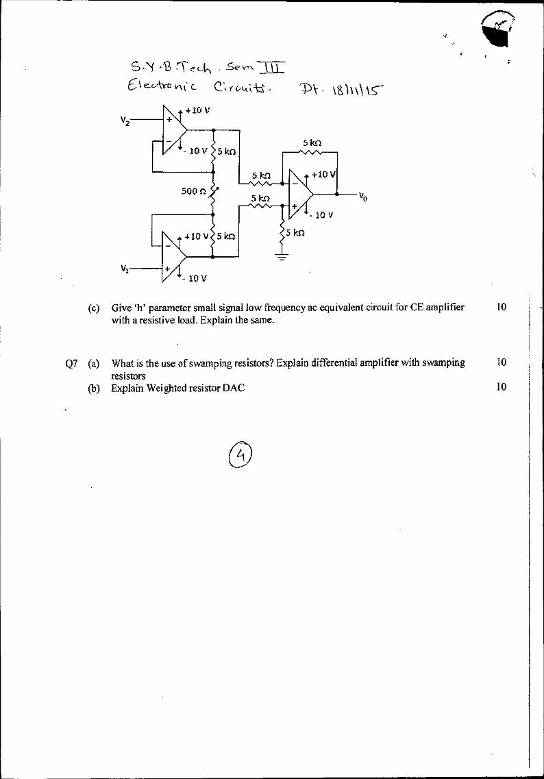
(c) Give 'h' parameter small signal low frequency ac equivalent circuit for CE amplifier 10 with a resistive load. Explain the same.
Q7 (a) What is the use of swamping resistors? Explain differential amplifier with swamping 10 resistors
(b) Explain Weighted resistor DAC 10

Question No
Q1(a)
(b)
(c)
Q2(a)
(b)
(c)
Q3(a)
(b)
21
-a x-r \ (2 - nra Prove that V x
r" e+2
Obtain the half range sine series for
2x 7E 0 < x < —
f (X) 3 3 it -x
< x <7c 3 3
(c) cc, . Prove that fsm 2t +sin 31 di -
3tr
te' 4
1 Evaluate E'
{82 (s_1)}
a r Prove that V
(a- . a- -
n(i)
r" In rn+2
Obtain the Fourier series for
( Find Laplace transforms of f (t) = t sin t )2
et j Evaluate by Green's thm 4 e" (sin ydx +cos ydy) where C is the
c rectangle with vertices (0, 0), (n/0) (a, it/2) & (0, a/2).
Obtain the Fourier Series for f (x) = x2 in (0,270
f (x)= -IT< X <0
5 Thn RA-t-re vneLth c1/42
S rs-CCS- Inj Bharatiya Vidya Bhavan s
Sardar Patel College of Engineering (A Government Aided Autonomous institute)
Munshi Nagar, Andheri (West), Mumbai - 400058. End Semester Exam
November 2015 ctS3/4-{ A" e Max. Marks: 100
Duration: 03 hours
Class: S.Y.Btech Semester: 111 Program:Electrical Name of the Course: Engineering Mathematics III Course Code : BTE201 Instructions: 1. Question No 1 is compulsory.
2. Attempt any four questions out of remaining six. 3. Each question has a 6-6-8 marks break up.(Ansvvers to sub questions should be written together) 4. Assume suitable data if necessary.
Maximum Marks

5 B - .5 e mitt' - n rt.) di') ern 4i 03 0)3— Q4(a) Obtain complex form of the I;ourier series for -1.611
f(x)=e 0<x<27r
(b) Evaluate E {c2, sin 2t cosh t
(c) Verify Divergence Theorem for F =4x i - 2y2 j+z2 k taken over the
bounded by the cylinder x2 + y2 = 4, z = 0, z = 3
Q5(a)
(b)
(c)
Q6(a)
(b)
(c)
Q7(a)
(b)
(c).
Prove that the set of functions {1, sin x, cos x, sin 2x, cos 2x,
is orthogonal over (0,270 and construct a corresponding orthonormal
set
a x r . is a solenoidal vector
r"
Prove using convolution theorem
1 - (sin at + at cos at)
2a
If S is the acute angle between the surfaces xy2z = 3x + z2 and
3
71(i
Verify Stoke's theorem for the vector field F = (x2 - y2 ) i + 2xy j over
the box bounded by planes x = 0, x = a, y = b, z = C if the face z = 0 is
cut.
{Evaluate: .e'l log
Find Laplace transforms of f = sin Vi
If f (x) = x 0 x 2
Find half range cosine series using Parseval's identity deduce
2r4 1 1 1 - + + + 96 14 34 54
Prove that
Evaluate: .E1 S2 ± 2s + 3
}(s2 + 2s + 2)(s2 + 2s + 5)
S2
(s2 +a2)2
3x2 -y2 + 2z =1 at point (1,-2,1) . Show that cos0 =
52 + b2
S2 ± a2

s.•\(.E.-cezAr . CElec4)Sern_111
El coky3 cca 0-th w CPA< - Sardar Patel College of Engineering
Bharatiya V idya Bhavan's (A Government Aided Autonomous Institute)
Munshi Nagar, Andheri (West), Mumbai — 400058. Re-Exam
January 2015
Max. Marks: 100 Class: .§,I15sh Name of the Course: ElectricalNetworks Instructions: 1. Question No 1 is compulsory. 2. Attempt any four questions out of remaining six.
3. In the absence of any data, make suitable assumptions and justify the same.
4. Figures to the right indicate full marks.
Given a polynomial P(s) = s5 2s4 4s2 + 11 s -I- 10 . Apply Routh Hurwitz criterion and determine number of roots with positive real part, negative real part and zero real part.
(b) For an electrical network in Fig. below, calculate impedance Z(s) at complex frequency s = jl tad/sec.
2- S
1
ci) 52+2.5+17
Construct pole — zero plot of a transfer function H(s) = s2+3 s+2 . Comment on
the stability.
In the following network, the switch is closed at t=0. Evaluate current i and voltage v at t=0_ and t=ic.
Semester: III Duration: 3 Hr. Program: Electrical Course Code : BTE203
Mcts+e,r (PO e
Question No.
Ql(a)
Max. Marks
05
05
05
05
Cu
O6
a
10
10
Pt
Iry
6 v
s Brrecin . Ctk tusk ) E‘t cA,n tea t--1-eA-tocrYVA 1)\- • 6001\16.
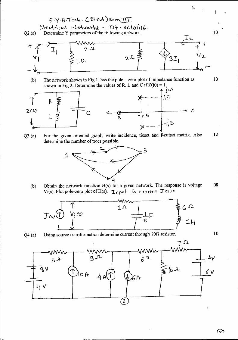
Q2 (a) Determine Y parameters of the following network.
152-
(b) The network shown in Fig 1, has the pole — zero plot of impedance function as shown in Fig 2. Determine the values of R, L and C if ZOO) = 1.
3 5
2.0-2 --)
5
Q3 (a) For the given oriented graph, write incidence, tieset and &outset matrix. Also 12 determine the number of trees possible.
3
(b) Obtain the network function H(s) for a given network. The response is voltage 08 Vi(s). Plot pole-zero plot of H(s). ern put Cs C_Lj new) T es)
WA.AAr j .12.
Tcs)
Q4 (a) Using source transformation determine current through 10E2 resistor. 10
52_

HiitILH° 1 Vir F v
s(Js ) sew( 6‘echri ckk Nek-wovkcs -D-. o gko‘\ 14
(b) Obtain Norton's equivalent circuit across a-b and hence calculate the current through 10O resistor.
10
2-V 10 J2-
Q5 (a) In a circuit shown below, the switch is shifted to position 2 at t=0. Find the 10 current v (t) fort? 0.
For a network given below, switch is closed at t=0. Determine current i(t) 10 (b)
assuming zero initial conditions in the elements.
---2±
6 g,
Q6 (a)Realize the Caur I and II forms of impedance function Z(s) —
(5+2)(s+6) •
(b) s(s+4)(s+8) Realize the foster I form of impedance function Z(S) — (s+1)(s+6) •
Q7 (a) For a series RLC network derive the expression for resonant frequency, half 10 power frequencies and bandwidth. Determine these values if R= loon, L=0.5 H and C= 0.4 µF.
08
(b) Determine loop currents 11, 12, 13.
10
Lao°

2-° S •\frb :Vain - 61 cik" stAnn-IIE
Bharatiya Vidya Bhavan's
Sardar Patel College of Engineering (A Government Aided Autonomous Institute)
Munshi Nagar, Andheri (West), Mumbai — 400058. End Semester Exam
November 2015 Max. Marks:
Name of
Instructions:
Class: S.Y.B.Tech. 100 Duration: 3 hrs
Semester: III Program: Electrical the Course: Integrated Circuits Course Code : BTE204
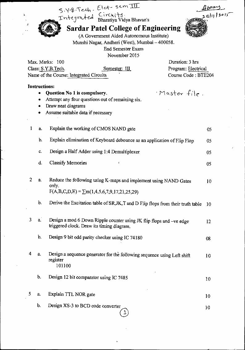
• Question No 1 is compulsory. • 1'1 cuSfel- r • • Attempt any four questions out of remaining six. • Draw neat diagrams • Assume suitable data if necessary
1 a. Explain the working of CMOS NAND gate 05
b. Explain elimination of Keyboard debounce as an application of Flip Flop 05
c. Design a Half Adder using 1:4 Demultiplexer 05
d. Classify Memories 05
2 a. Reduce the following using K-maps and implement using NAND Gates only.
10
F(A,B,C,D,E) = Em(1,4,5,6,7,9,17,21,25,29)
b. Derive the Excitation table of SR,JK,T and D Flip flops from their truth table 10
3 a. Design a mod 6 Down Ripple counter using JK flip flops and —ve edge triggered clock. Draw its timing diagram.
12
b. Design 9 bit odd parity checker using IC 74180 08
4 a. Design a sequence generator for the following sequence using Left shift register
10
101100
b. Design 12 bit comparator using IC 7485 10
5 a. Explain TTL NOR gate 10
b. Design XS-3 to BCD code converterr:\ 10

r cut -i-S - 1--)"‘ - \ 1115.- 6 a. As an application of Shift Registers Explain the working of 4 bit Twisted 10
Ring counter with the timing diagram.
b. Write short note on Programmable Logic Array 10
7 a. Implement the following 10 f(A,B,C,D) = Em(0,1,3,5,7,8,9,10,12,13,15) using
I. Single 8:1 Mux 2. Single 4:1 Mux
b. State and Prove De-Morgan's Theorems 04
c. Implement OR gate using NAND gates only 04
d. Convert (123.43)10 to its binary equivalent. 02

s (6 5c
\ cjA ri LcLA tea - Bharatiya Vidya Bhavan's
Sardar Patel College of Engineering (A Government Aided Autonomous Institute)
Munshi Nagar, Andheri (West), Mumbai —400058. End Semester Exam
November 2015
LiJ 241ttiLC
Max. Marks: 100 Class: S. Y. B. Tech. Semester: III
Name of the Course: Electrical Machines - I Instructions: 1. Question No 1 is compulsory. 2.- - Attempt any-four-questions-eut-ofremaining_six.
3. Draw neat diagrams 4. Assume suitable data if necessary
Duration: 3 hours Program. B. Tech. Course Code : BTE205
ricks i t' •
Question No
Maximum Marks
QI Explain the following. (Any Four)
(a) Magnetic properties of material. 05
(b) Parallel operation of single phase transformer. 05
(c) Cogging phenomenon in induction motor. 05
(d) Three point starter for dc shunt motor 05
(e) Transformer harmonics. 05
Q2 (a) Explain the principle of electromechanical energy conversion and hence the expression of energy stored in magnetic field.
10
(b) Derive the torque in doubly excited magnetic field with respect to electromechanical energy conversion.
10
Q3(a) Draw the complete phasor diagram of transformer with resistance and leakage reactance.
04
(b) A 50 kVA, 2200/110 V transformer when tested gave the following results: O.C. Test (L.V.Side): 400W, 10 A, 110 V. S. C. Test (H.V.Side): 808 W, 20.5 A, 90 V. Compute all the parameters of the equivalent circuit referred to the H.V. side and draw the resultant equivalent circuit.
08
(c) Draw and explain the different vector groups in connection with three phase transformer.
f--.--‘
08

s . S-e ALL
E. ‘ CAA 0 CAA r- i emh % bits _ J... - 4-'T- e_(, /II 11,,
Q4(a) Two 100 kW, single phase transformers are connected in parallel. One transformer has an ohmic drop of 0.5% at full load and an inductive drop of 8% at full load current. The other has an ohmic drop of 0.75% and inductive drop of 2%. Show how will they share a load of 180 kW at 0.9
power factor.
08
(b) Explain the transformer switching current transients in detail. 06
(c) Draw the connection diagram of an autotransfonner and hence prove that autotransformer uses less copper as compared to two winding transformer.
06
Q5(a) Three phase, 50 Hz, 8 pole, induction motor has full load slip of 2%. The rotor resistance and stand still rotor reactance per phase are 0. 001 LI and
0. 005 12 respectively. Find the ratio of the full load to maximum torque and the speed at which the maximum torque occurs.
06
(b) Explain the different methods of speed control of three phase induction
motor.
08
(c) Explain the basic principle of operation and construction of three phase
induction motor.
06
Q6(a) A 3-phase, 440V, 50Hz, 4-pole, star connected induction motor has a full-load speed of 1425 rpm. The rotor has an impedance of (0.4+j4) CI and rotor/stator turn ratio of 0.8. Calculate (i) full-load torque (ii) rotor current and (iii) full load rotor Cu loss (iv) power output if windage and friction losses amount to.500 W (v) maximum torque and (vi) the speed at which it occurs (vii) starting current and (viii) starting torque.
16
(b) Explain the principle of operation of Induction Generator. 04
Q7 (a) Draw and explain the N/T, N/Ia, and T/Ia characteristics of DC Series Motor. Also, state the applications of DC Series Motor.
07
(b) A DC Series Motor takes 40A at 220V and runs at 800 r.p.m. If the armature and field resistance are 0.2 SI and 0.1 SI respectively and the iron and friction losses are 0.5 kW, find the torque developed in the armature.
What will be the output of the motor?
the speed below rated
08
05 (c) Explain the method of speed control to control
speed for DC Shunt and Series Motor. //TN,

Eycom Li k oi -1 4
S •N( •CC tut-) S-c
1%---\••kvney c ecA cle.v• LIM-e.3 • Bharatiya Vidya Bhavan's
Sardar Patel College of Engineering (Govt. Aided Autonomous Institute Affiliated to University of Mumbai)
Re-Examination — January 2016 Subject: Numerical Techniques Class: S. Y. B. Tech. (Electrical, Sem: III)
Date: January 9, 2016. Total Marks: 100
Note: 1. Solve any FIVE questions of the following. All questions carry equal marks.
2. Group the answers to all sub-questions together. M ctS -4-ey J'; k .
1. a (i) Explain the term Significant Digit, with suitable examples. (05)
(ii) Explain different types of errors that may occur in numerical computation and discuss concept of error propagation.
b. Obtain smallest positive root of the following equation using (i) False Position Method and (10)
(ii) Secant method correct up to four decimal places: .x3 — x —4 = 0
2. a. Use Simpson's -rd rule and Trapezoidal rule to evaluate
3
2
log e + x2 )dx by taking n = 6. 0
(10)
Comment on the result.
b.
Using Newton Raphson method, find a root of the following equation, assuming initial (10)
guess as zero: f(x)= x 3 — 3 .z 2 —5.5x + 9.5 = 0 .
3. a Solve the following system of equations using Gauss elimination method. (10)
2x1 +x2 + 4; + 7; =1
—4x1 +x2 —6; —13; =
4x1 + 5; + 7x3 + 7; = 4
— 2x, + 5x2 — 4x3 = —5
b. Solve the following system of equations using Gauss— Seidel Iterative method:
(10)
3x1 —0.1; — 0.2x3 = 7.85
0.1x1 +7; —0.3; =-19.3
0.3x, —0.2; +10; = 71.4
(05)
71-e4,, CC-1cup S-cwtkl 1-Avorneyccea ttutcs- 'D\- 59101)1,4 .
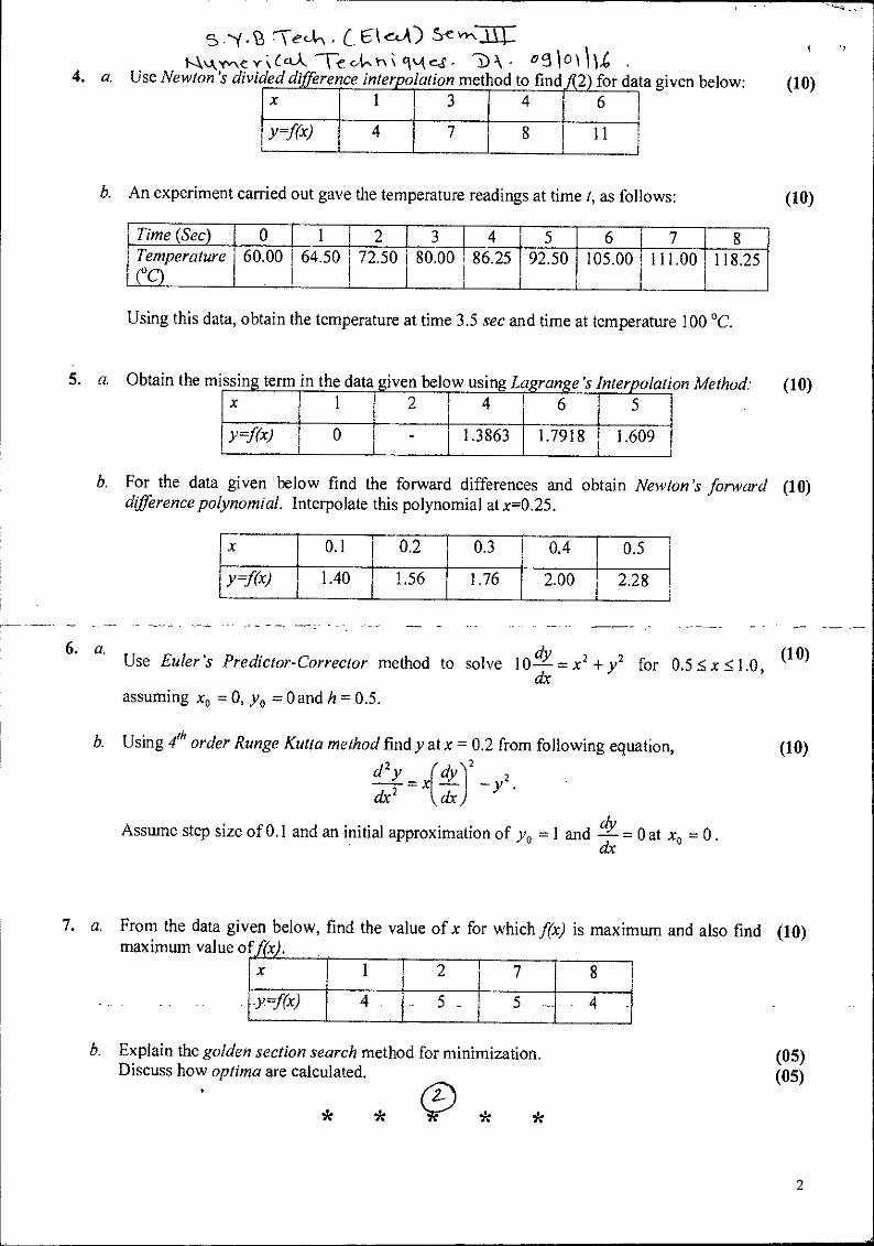
4. a. Use Newton's divided djfference interpolation method to find 2 for (10)
b. An experiment carried out gave the temperature readings at time t, as follows:
1 Time (Sec) 0 1 i 2 1 3 4 5 6 7 8 ! Temperature 1 1 co
1 60.00 I 64.50 1
I i I
72.50 1 80.00 I 1 I
1 86.25 92.50 105.00 1 111.00 I
118.25
Using this data, obtain the temperature at time 3.5 sec and time at temperature 100 °C.
x I 1 3 I I
4 i 6
y=f(x) ! I
4 7 8 11
(10)
i a. Obtain the missing term in the data given below using Lagrange 's Interpolation Method: (10) I x I 1 2 1 4
1 6 1 5 1 I I 1Y =fix)
1 0 - 1 1.3863 1.7918 1.609
1 1
b. For the data given below find the forward differences and obtain Newton's' forward (10) difference polynomial. Interpolate this polynomial at x=0.25.
I x I 0.1 I 0.2 I 0.3 I 0.4 I 0.5
y=f(x) 1.40 I 1.56 I 1.76 I 2.00 I 2.28 I
6. a. dY 2 (10) Use Euler 's Predictor-Corrector method to solve 10— = x + y2 for 0.5 5. x 1.0, dx
assuming xo = 0, yo = 0 and h = 0.5.
b. Using 4th order Runge Kutta method find y at x = 0.2 from following equation, (10) d 2 y (dy\,2
- y 2 . cfr 2 dr )
Assume step size of 0.1 and an initial approximation of yo =1 and —dy = Oat xo = 0.
dx
7. a. From the data given below, find the value of x for which f(x) is maximum and also find (10) maximum value o (x).
1i x . 1 2 1 7 8
i Yr-Rx) 4 5 4
b. Explain the golden section search method for minimization. Discuss how optima are calculated.
(05) (05)
2
Re, fere? rri Li 10
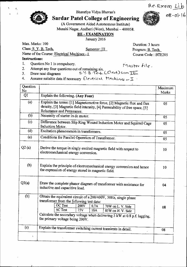
08-01-16 Bharatiya Vidya Bhavan's
Sardar Patel College of Engineering (A Government Aided Autonomous Institute)
Munshi Nagar, Andheri (West), Mumbai - 400058. RE - EXAMINATION
January 2016 Max. Marks: 100 Class: S. Y. B. Tech., Semester: III Name of the Course: Electrical Machines - I Instructions: 1. Question No 1 is compulsory. 2. Attempt any four questions out of remaining six. 3. Draw neat diagrams 4. Assume suitable data if necessary C c
Duration: 3 hours Program: B. Tech. Course Code : BTE205
ov..0-ty ke
eSs) S -cm jr Mad, I •
Question No
Maximum Marks
Q1 Explain the following. (Any Four)
(a) Explain the terms: [1] Magnetomotive force, [2] Magnetic flux and flux density, [3] Magnetic field intensity, [4] Permeability of free space, [5]
Reluctance and Permeance.
05
(b) Necessity of starter in dc motor. 05 (c) Difference between Slip Ring Wound Induction Motor and Squirrel Cage Induction Motor.
05
(d) Excitation phenomenon in transformers. 05 (e) Conditions for Parallel Operation of Transformer. 05
Q2 (a) Derive the torque in singly excited magnetic field with respect to electromechanical energy conversion.
10
(b) Explain the principle of electromechanical energy conversion and hence the expression of energy stored in magnetic field.
10
Q3(a) Draw the complete phasor diagram of transformer with resistance for inductive and capacitive load.
04
(b) Obtain the transformer
Calculate the primary
equivalent circuit of a 200/400V, 50Hz, single phase from the following test data:
lagging,
08 OC Test 200V 1 0.7A I 70W on L. V. Side SC Test 15V 1 10A , 85W on H. V. Side
the secondary voltage when delivering 5 kW at 0.8 p.1 voltage being 200V.
(c) Explain the transformer switching current transients in detail. 08
•3.-VccAn . LEI eck) Dai y; teketuki n.c.3 _ z
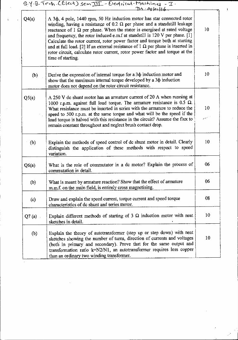
Q4(a)
. „
A 34), 4 pole, 1440 rpm, 50 Hz induction motor has star connected rotor winding, having a resistance of 0.2 0 per phase and a standstill leakage reactance of 1 0 per phase. When the stator is energised at rated voltage and frequency, the rotor induced e.m.f at standstill is 120 V per phase. [1] Calculate the rotor current, rotor power factor and torque both at starting and at full load. [2] If an external resistance of 1 Si per phase is inserted in rotor circuit, calculate rotor current, rotor power factor and torque at the time of starting.
10
(b) Derive the expression of internal torque for a 34) induction motor and show that the maximum internal torque developed by a 34) induction motor does not depend on the rotor circuit resistance.
10
Q5(a) A 250 V dc shunt motor has an armature current of 20 A when running at 1000 r.p.m. against full load torque. The armature resistance is 0.5 Q. What resistance must be inserted in series with the armature to reduce the speed to 500 r.p.m. at the same torque and what will be the speed if the load torque is halved with this resistance in the circuit? Assume the flux to remain constant throughout and neglect brush contact drop.
10
(b) Explain the methods of speed control of de shunt motor in detail. Clearly distinguish the application of these methods with respect to speed variation.
10
Q6(a) What is the role of commutator in a dc motor? Explain the process of commutation in detail.
06
(b) What is meant by armature reaction? Show that the effect of armature m.m.f. on the main field, is entirely cross magnetising.
06
(c) Draw and explain the speed current, torque current and speed torque characteristics of dc shunt and series motor.
08
Q7 (a) Explain different methods of starting of 3 12 induction motor with neat sketches in detail. .
10
(1) Explain the theory of autotransformer (step up or step down) with neat sketches showing the number of turns, direction of currents and voltages (both in primary and secondary). Prove that for the same output and transformation ratio k=N2/N1, an autotransformer requires less copper than an ordinary two winding transformer.
10
Li b - Re- Excti, Or-101-16
• CEA c-1-11/4 5-e 'tear
l_nke Ctki . •
Bharatiya Vidya Bhavan's
Sardar Patel College of Engineering (A Government Aided Autonomous Institute)
Munshi Nagar, A ndheri (West), Mumbai -- 400058. En.d Semester Exam
November 2015 Max. Marks: 100 Class: S.Y.B.Tech. . Semester: III Name of the Course: Integrated Circuits
Duration: 3 hrs Program: Electrical Course Code : BTE204
Instructions: • Question No 1 is compulsory. • Attempt any four questions out of remaining six. • Draw neat diagrams • Assume suitable data if necessary
I'lekSA-er le •
1. a. Reduce the following using K-maps and implement the circuit. 05 F(A;B,C,D) = 1m(1,4,5,6.7,9,15)
b. Explain the different types of clock available for sequential circuits 05
c. Explain the concept of Bushing in counters with an example. 05
d. Explain the working of CMOS NOR gate 05
2. a. Design a controlled addition /subtraction circuit using IC 7483. 10
b. Explain the following terms related to Logic Families 10 i. Fan out and Fan in
Noise immunity iii. Current and Volta:O. Parameters iv. Speed of operation v. Power Dissipation
3. a. Do the following 10 i. (101101)2= (?)ui
( AC7 )16 = ( ? )8 iii. (10011)2 — (11001)2 using Ps compliment method iv. (47)io— (?)x5-3 v. (I. 111)2 (11)2
b. Suppose the receiver receives hamming code data as 1011111. Find out if there 10 is any error or not and correct it if error is present.
4. a.
s. -1764,1-1 • (--E•leLik-) strC31C Ct•r-C‘tiil - 07100 ,
Implement the following using 8:1 Max.
f= ABC + BCD +ABC
10
b. Implement Binary to Gray code converter. 10
5. a. Explain the Race condition of .11{ flip flop and how it can be eliminated. 10
Explain the working of Master Slave IX flip flop
b. Explain the working of 4 bit Ring counter with the timing diagram 10
6. a. Design a mod 9 ripple counter using T flip flop along with the timing diagram. .1-0
b. Explain the different types of registers. 10
1. a. Write Short Note on memories 10
b. Explain in detail any two applications of Flip Flops. 10
t 6°—j\1\AAC—s----v NI
;fl uo T1, 7_ o s;rvA---
Lib Pe-Exc.:0in 0C-01-16
s C441rOni C- C- cbk -Ci ° ‘1 I‘
Bharatiya Vidya Bhavan's
Sardar Patel College of Engineering (A Government Aided Autonomous Institute)
Munshi Nagar, Andheri (West). Mumbai —400058.
Re Exam
January 2016
Duration: 3 hours
Program: Electrical Engineering
Course Code : BTE202
Max. Marks: 100
Class: S.Y. B. Tech.
Name of the Course:
Instructions:
1. Question No I is compulsory.
2. Attempt any four questions out of remaining six.
3. Draw neat diagrams
4. Assume suitable data if necessary
Mos --er c le •
Semester: Ill
Electronic Circuits
(21
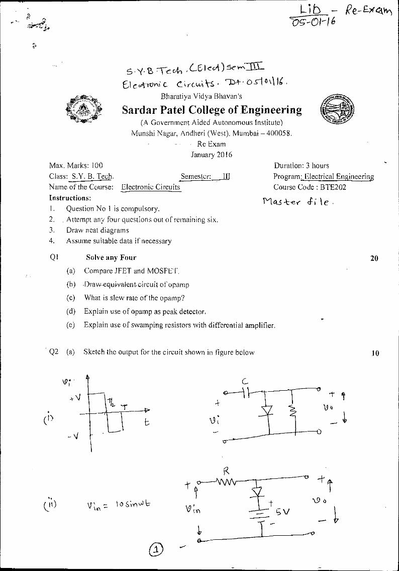
Solve any Four 20
(a) Compare WET and MOSFET.
(b) Drawequivaleacircuit of opamp
(c) What is slew rate of the opamp?
(d) Explain use of opamp as peak detector.
(e) Explain use of swamping resistors with differential amplifier.
Q2 (a) Sketch the output for the circuit shown in figure below 10
120 kn
AAI
Vi 120 p.V
.-reolA CEl edc sew1L-
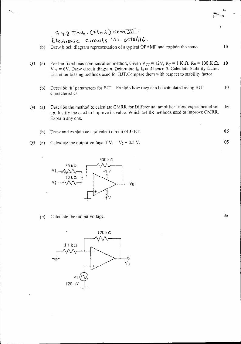
E c •oratAs ro+ os-‘0 \ 16 . (b) Draw block diagram representation of a typical OPAMP and explain the same. 10
Q3 (a) For the fixed bias compensation method, Given Vcc = 12V, Rc = 1 K CI, 123 = 100 K. £2, 10 VcE = 6V. Draw circuit diagram. Determine lb. le and hence p. Calculate Stability factor. List other biasing methods used for BJT.Compare them with respect to stability factor.
(b) Describe -11* parameters far BYT. Explain how they can be calculated using BIT 10 characteristics.
Q4 (a) Describe the method to calculate CMRR for Differential amplifier using experimental set 15 up. Justify the need w improve its value. Which are the methods used to improve CMRR. Explain any one.
(b) 'Draw and explain ac equivalent circuit of J FET. 05
Q5 (a) Calculate the output voltage if V I = V2 = 0.2 V. 05
33€ RU 33 k f -•*;
7, F
v2 --AVVV-1 I
(b) Calculate the output voltage. 05
2 ka
10 V 1
ko
5.y. rrnh, ,C6ick)sc JIC w)
bleukronic Crct( kS °1114
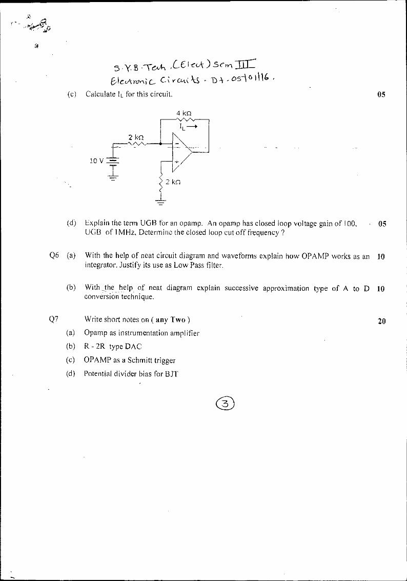
(c) Calculate IL for this circuit. 05
4 kca \At-Q-1
9
(d) Explain the term UGB for an opamp. An opamp has closed loop voltage gain of 100, • 05 UGB of 1MHz, Determine the closed loop cut off frequency ?
Q6 (a) With the help of neat circuit diagram and waveforms explain how OPAMP works as an 10 integrator. Justify its use as Low Pass filter.
(b) With the help of neat diagram explain successive approximation type of A to D 10 conversion technique.
Write short notes on ( any Two)
20
(a) Opamp as instrumentation amplifier
(b) R - 2R type DAC
(c) OPAMP as a Schmitt trigger
(d) Potential divider bias for BJT

oirol-1 4 cAn se ofillEE C et ce-k)
Gni ;y1 nki kf.,,,kki us -111: Bharatiya Vidya Bhavan's
Sardar Patel College of Engineering (A Government Aided Autonomous Institute)
Munshi Nagar, Andheri (West), Mumbai — 400058. End Semester Re-Examination
November 2015
Max. Marks: 100 Duration: 03 hours
Class: S.Y.Btech Semester: III Program:Electrical
Name of the Course: Engineering Mathematics III Course Code : BTE201
et 5 }C-r Pie -
Instructions: 1. Question No 1 is compulsory.
2. Attempt any four questions out of remaining six. 3. Each question has a 6-6-8 marks break up.(Answers to sub questions should be written
together) 4. Assume suitable data if necessary.
Find L {cos 2t sin t
et
Maximum Marks
Verify Green's theorem in the plane for
4 (3x2 —8y2 )dx + (4y — 6xy)dy where C is the boundary of region
defined by y = & y = x2. Obtain the Fourier Series for f (x) = x in (0,2n)
Evaluate: L-1 3s +1 (s +1)4
Prove that v(; . = , where a is a constant vector.
Obtain the Fourier series for 2x 1+— —n<x<0
2x 1-- 0<x<n
It
Prove that r )
" ?I +
rn+2
Obtain the half range sine series for
2x Ox5-7E 3 3
7C - X -1r 5 x 5 it
3 3
Question No
Q1(a)
(b)
(c)
Q2(a)
(b)
(c)
Q3 (a)
(b)
f (x) =
(c) 6 Show that Jo-2' sin' t dt = —
65 0

1 (s2 a2
Find the angle between the surfaces x
at the point (2,-1,2)
.e1 = 1 , ( 2a3
sin at - at cos at)
y2 +z2 =98cz = x2 +y2-3
-0-In • se - 0,e-erirtj NA-In€4„4-cs :TT
a'r .5 ;110111C : Q4(a) Obtain complex form of the Fourier series for f (x) = em
{ Evaluate B e-2t sin 2t cosh t t
Verify Divergence Theorem for
F=((2 - yz)1+ (y2 - zx)Aj+ (z2 - xy)k taken over the rectangular parallelopiped 0 < x < a, 0 < y 5. b, 0 < z < c.
Show that the functions cit (x) = 1 y2 (x) = x843 = -1 (3x2 -1) are 2
- vector and r = . + yj + zk prove that
2s2 - 4
A A A
Verify Stoke's theorem for the vector field f --.(2x - y)i - yz2 j - y2 zk
over the upper half surface of x2 + y2 + z2 = 1 bounded by its projection on the XY-plane.
.t 1 s2 + b2
i log I
Evaluate: s2 + a2
Find Laplace transforms of f (t)= -.11+ sin t
By using the sine series for f (x) = 1 in0 <x <2t .Hence using R2
parseval identity show that — 8 34 =1+-1, + —1 5, ,
7, +.... ,
(b)
(e)
Q5(a)
(b)
(c)
Q6(a)
(b)
(c)
Q7(a)
(b) (c)
orthogonal over (-1,1)
If -a is a constant
curl (a x r = 2a
Find .t1 {(s + 1)(s - 2)(s - 3)}
Prove using convolution theorem