Embed Size (px)
Citation preview

NEXT GENERATION TRANSPORTNETWORKSData, Management, and Control Planes
NEXT GENERATION TRANSPORTNETWORKSData, Management, and Control Planes
Manohar Naidu EllantiSteven Scott GorsheLakshmi G RamanWayne D Grover
^y Springer

Manohar Naidu Ellanti Steven Scott GorsheLakshmi G. Raman Wayne D. Grover
Next Generation Transport NetworksData, Management, and Control Planes
Library of Congress Cataloging-in-Publication Data
A CLP. Catalogue record for this book is availablefrom the Library of Congress.
ISBN 0-387-24067-5 e-ISBN 0-387-24068-3 Printed on acid-free paper.
© 2005 Springer Science+Business Media, Inc.All rights reserved. This work may not be translated or copied in whole or in part withoutthe written permission of the publisher (Springer Science+Business Media, Inc., 233 SpringStreet, New York, NY 10013, USA), except for brief excerpts in connection with reviews orscholarly analysis. Use in connection with any form of information storage and retrieval,electronic adaptation, computer software, or by similar or dissimilar methodology nowknow or hereafter developed is forbidden.The use in this publication of trade names, trademarks, service marks and similar terms,even if the are not identified as such, is not to be taken as an expression of opinion as towhether or not they are subject to proprietary rights.
Printed in the United States of America.
9 8 7 6 5 4 3 2 1 SPIN 11054764
springeronline.com
Contents
Preface ix
Acknowledgements xiii
1. INTRODUCTION TO TRANSPORT NETWORKS 1
1.1. General Introduction 1
1.2. What is a Transport Network? 3
1.3. Summary of the Chapter Contents 21
1.4. What's Happening with Transport Networks? 25
1.5. Conclusions 37
2. SWITCHING 39
2.1. Introduction 39
2.2. Taxonomy 40
2.3. Space Division Switching 42
2.4. Time Division Switching 59

vi Contents
2.5. Packet Switching 73
2.6. Interconnection Networks 80
2.7. Centralized and Distributed Switching 91
2.8. Fault Tolerance of Switching Networks 94
2.9. Conclusions 98
3. SONET and SDH 101
3.1. Introduction 101
3.2. SONET/SDH Layering Principles 107
3.3. SONET/SDH Frame Format 112
3.4. SONET Overhead Definitions 125
3.5. OAM&P Functions and Capabilities 135
3.6. Payload Mapping 146
3.7. Pointers and Justification 164
3.8. Synchronization 170
3.9. Sub-STS-Interfaces 172
3.10. In-band Forward Error Correction 176
3.11. Conclusions 177
4. NEXT GENERATION TRANSPORT TECHNOLOGIES 181
4.1. Introduction 181
4.2. Virtual Concatenation (VCAT) and the Link Capacity AdjustmentScheme (LCAS) 182
4.3. Generic Framing Procedure (GFP) 198
4.4. Resilient Packet Ring (RPR) 214
NEXT GENERATION TRANSPORT NETWORKS vii
4.5. Optical Transport Networks (OTN) 230
4.6. General Conclusions 262
5. MANAGEMENT ARCHITECTURES 267
5.1. Introduction 267
5.2. What and Why of TMN 268
5.3. Architectures of TMN 273
5.4. Relationship Between TMN Architectures 299
5.5. Relationship Between Control and Management Planes 300
5.6. TMN Reality Check: What has Gone Wrong with TMN? 302
5.7. Conclusions 304
6. MANAGEMENT INFORMATION MODELS 307
6.1. Introduction 307
6.2. Transport Architecture 313
6.3. Generic Information models 318
6.4. SDH Information Models 321
6.5. Conclusions 375
7. MANAGEMENT TECHNOLOGIES 377
7.1. Introduction 377
7.2. Management Protocols/Languages Galore 379
7.3. Information Specification Languages 380
7.4. Information Access and Transport Protocols 420
7.5 Conclusions 480
viii Contents
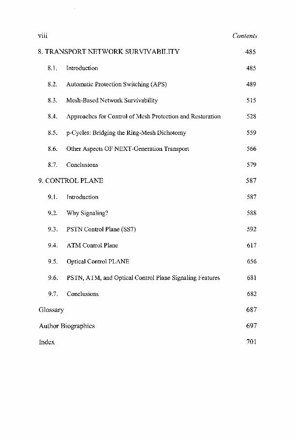
8. TRANSPORT NETWORK SURVIVABILITY 485
8.1. Introduction 485
8.2. Automatic Protection Switching (APS) 489
8.3. Mesh-Based Network Survivability 515
8.4. Approaches for Control of Mesh Protection and Restoration 528
8.5. p-Cycles: Bridging the Ring-Mesh Dichotomy 559
8.6. Other Aspects OF NEXT-Generation Transport 566
8.7. Conclusions 579
9. CONTROL PLANE 587
9.1. Introduction 587
9.2. Why Signaling? 588
9.3. PSTN Control Plane (SS7) 592
9.4. ATM Control Plane 617
9.5. Optical Control PLANE 656
9.6. PSTN, ATM, and Optical Control Plane Signaling Features 681
9.7. Conclusions 682
Glossary 687
Author Biographies 697
Index 701
Preface
Are transport networks important? To society? To communicationsengineering as a field? What about the "fiber glut"? Isn't bandwidthalready essentially abundant and free? Despite these and other popularmisconceptions, metropolitan, national and international fiber-optic basedtransport networks are actually one of the engineering marvels of 20thcentury and have become fundamental infrastructure, crucial to current andfuture economies and societies. Like many basic civil infrastructures, suchas water, roads, power, public health, such engineered systems are almostinvisible to the layperson, especially when they work nearly perfectly. Butmajor and unexpectedly severe economic, personal, and societal impactsarise if these systems are removed even temporarily. Like these other basicinfrastructures, the fiber optic transport network is now of fundamentalimportance to our economy, lifestyles, education, entertainment, finance andso on. Advances in computing, wireless, mobility, multi-media, HDTV, theInternet, all come to a halt if it were not for the capabilities of the underlyingtransport network on which they all ride. The public sometimes asks "Whatabout wireless and cell phones, with them we don't need fiber," but this isbased only on technical unawareness that every cell-phone call relies onfiber optic transport for trunking between switches and base stations tocomplete the calls. Similarly, every DSL and cable modem user of highspeed Internet access is also a user of the fiber transport backbone. These"access" technologies, to which we can add phone and bank ATM machines,are best known to us all as users because it is these systems that are "in ourface." But all of them rely on a single, ubiquitous, relatively unseentransport network operating behind the scenes.

x Preface
But there are also important ways in which the transport network differsfrom the older utility infrastructures mentioned above. Intelligence,survivability, and flexibility is one set of features, but the potential forproductivity and wealth impact is an enormous differentiator. In a recentreport by the Allen Consulting Group [1], it was estimated that achieving thegoal of "true broadband" networking (over 10 Mbps to every home andoffice) can result in national productivity growth of 10-12%. They commentthat this is the fundamental reason why governments should makeinvestment in research networks, ICT, and competitive telecom their numberone priority. In their view no other technology, even nanotechnology or bio-informatics is seen as having such a direct and measurable impact onnational and global productivity. This means jobs. This means wealthcreation. This means a plethora of still unimagined new educational,business, research, recreational, and entertainment possibilities. Transportnetworks are thus of fundamental importance to a society that wants to reachhigh and grasp this "prize."
There are many different ways to approach the topic of transportnetworks. Books typically focus on either the transport (data) plane or thecontrol and management planes, depending the authors' expertise. In orderto reduce overhead costs and increase the speed and flexibility of offeringnew services, however, carriers continually look to automate theiroperations, administration, maintenance, and provisioning (OAM&P) tasks.The result is an increasingly closer linkage between the transport,management, and control plane technologies. New transport planetechnologies are unlikely to be adopted unless they offer OAM&P savings,and new OAM&P tools are unlikely to be adopted unless they can work withthe current transport plane infrastructure. One of the objectives of this bookis to provide a comprehensive, balanced overview of the transport,management, and control plane technologies. The book is organized withone section devoted to each of these three planes.
Another objective of this book is to provide a useful tutorial andreference information for current and next generation telecommunicationsnetwork technologies. Since it is not practical for carriers to replace theirexisting infrastructure, even new equipment and network deployments willneed to be compatible with the existing technologies such as SONET/SDH.Both the boom and bust in the telecommunications industry spawned anumber of new technologies that are expected to become important in thecoming years. Many of these technologies are not covered in existing books.This book provides a detailed tutorial overview of these new technologies,seeking to put them into the proper context with respect to interworking withexisting networks and technologies. Examples include the Generic FramingProcedure (GFP), the Link Capacity Adjustment Scheme (LCAS), the
NEXT GENERATION TRANSPORT NETWORKS xi
Resilient Packet Ring (RPR) protocol, Automatic Switched Optical Network(ASON), and XML/SOAP (Simple Object Access Protocol) basedmanagement technologies. Since TL1 and OSMINE are important for manyNorth American carriers and vendors, a brief discussion of both is includedin the management section. Also, discussion of multi-stage switching usedin modern digital cross-connects and other switching equipment can befound in Chapter 2 as part of transport technologies. The critical, relatedtopic of network protection is also covered extensively in Chapter 8 to roundthe book.
What do the four of us especially have to offer on the topic? The authorsthat Manohar assembled for this book have each been recognized by theirpeers for their contributions in their respective areas. Each of us has morethan 20 years of experience in telecommunications research, productdevelopment, and/or standards. Steve and Lakshmi are both recipients of theCommittee Tl Alvin Lai Outstanding Achievement Award for theirstandards contributions. Wayne is an IEEE Fellow for his contributions tosurvivable and self-organizing broadband transport networks. (Morecomplete biographies of each author appear near the end of the book prior tothe Index.) We divided the chapter responsibilities as follows: Manohar -Chapters 2, 7 and 9; Steve - Chapters 1, 3, and 4 (and contributing to 8);Lakshmi - Chapters 5 and 6; and Wayne - Chapter 8.
Due to the multiple authors, the book may have some inconsistencies instyle, despite our best efforts to harmonize. If our readers identify anyeditorial or other types of errors that escaped us, please bring them to ourattention - we will update our companion website with corrections totypographical or technical errors as soon as we discover them. This being avery detailed book - we are bound to have some errors and the companionwebsite should be helpful for those looking for corrections. For anyquestions related to this book, please email Steve Gorshe([email protected]).
Manohar N Ellanti Steven S. GorsheFremont, California Beaverton, Oregon
Lakshmi Raman Wayne D. GroverAlbany, Oregon Edmundton, Canada
January 2005
[1] Allen Consulting Group, "True Broadband: Exploring the economic impacts," AnEricsson contribution to public policy debate, September 2003, available online:http://www.ericsson.com.au/broadband/true broadband.asp
Acknowledgements
Manohar would like to thank his wife, Sumati, and children, Mounika,Vivek for letting him spend time working on this book- numerous versionsand revisions of chapters, book proposals and correspondence related to thisproject. Manohar also likes to thank his co-authors for coming together onthis project
Steve would like to primarily thank his wife Bonnie, and boys Alex andIan for their patience as I worked on the book for many an evening. I wouldalso like to thank Vern Little and Stacy Nichols at PMC-Sierra for theirsupport in allowing me to combine some of my work on the book with mywriting of white papers for PMC-Sierra.
The authors would like to express their thanks to the followingindividuals for their review and input to the material in this book. ThomasAlexander, Tim Armstrong, Richard Cam, Robert Crestani, Huub vanHelvoort, Patrice Plante, Winston Mok, Anthony Sack, and Trevor Wilson,Harinder Singh, Rao Lingampalli, Manish Vichare, Mahesh Subramanian,Chiradeep Vittal, Steve Langlois. Manohar would particularly like tomention and thank Jackie Orr in helping with review and contribution tosection on OSMINE, a very rarely covered material in other books. Specialthanks to Lyndon Ong, who is involved in ITU, OIF and other standardsbodies related to control plane, in helping with review of Control Planechapter and contributing to parts of this chapter. Authors would like to thankMelissa Guasch at Kluwer/Springer for helping with reviews and generalcorrespondence related to this project. Special thanks to Alex Green, theeditor at Kluwer/Springer for providing support and encouragement.

Chapter 1
INTRODUCTION TO TRANSPORT NETWORKS
1.1. GENERAL INTRODUCTION
Telecommunications transport networks are the largely unseeninfrastructure that provides local, regional, and international connections forvoice, data, and even video signals. In fact, most "private" networks areimplemented by leased connections through the public transport networkinfrastructure. Transport networks in telecommunications and datacommunications networks are changing rapidly with the introduction of newtechnologies that address the need for new value-added services, highavailability, and integration. There has been a considerable amount of effortfrom equipment vendors and network providers to bridge and unifypreviously dedicated networks to serve the data and telecommunicationsmarket. This effort is reflected in the output of several standards bodies andindustry groups and the field trials of new equipment and services.
In the midst of this change, there are two trends that have made transportnetworks more visible to end-users. The first is the desire for higherbandwidth multi-media enterprise network connections. The enterprisenetwork administrators building the networks have to take into account thevarious capabilities of the transport networks, including whether they canprovide an integration of voice and data services or whether each must becarried on a separate sub-network. The second trend is the increasingderegulation and/or privatization of national telephone carriers. Forexample, U.S. long distance carriers such as AT&T, Sprint, and MCI cannow bypass the local telephone companies, effectively providing directaccess for enterprise customers into their transport networks.

2 Chapter 1
Who should care about transport networks, and why? As indicatedabove, those who construct or administer enterprise networks are oftenconstrained by the capabilities of the public transport networks. Familiaritywith transport network technology will allow them to make appropriatedecisions regarding WAN connectivity. Service providers working toincrease revenues with the introduction of value added services wouldbenefit from understanding how to best utilize the capabilities of the newtechnologies. There is still a substantial market for transport networkequipment, and clearly anyone involved in developing these products needsto be familiar with the existing and emerging technologies. Policy makersshould also be familiar with the transport network technologies and theirpotential impact on policy decisions. Those in academic circles who use ordo research related to telecommunications networks also need a thoroughunderstanding of their technology, and the practical constraints onintroducing new technologies.
The motivation for this book is to offer, in a single source, informationthat allows readers with differing requirements to gain a complete picture ofthe different dimensions of transport networks along with practicalperspectives. With the large number of industry standards specificationsassociated with various aspects of transport networks, it is often difficult toget the big picture view of what will be deployed in the future and how itwill facilitate a service provider to meet their business objectives. Bybringing together in one place various topics that are spread across multiplespecifications, the book enables readers with different goals not only tounderstand the complete picture but also to access details. The authors alsoattempt to provide insights on not only what the existing technologies are,but also how they evolved and the constraints and drivers for the futuredirections. The style of the book is to begin chapters and sections withtutorial background for readers that are new to the subjects. The chaptersthen move to a more detailed treatment that can be used as a reference forreaders more familiar with the subjects. As such, the book is aimed atreaders with different levels of prior knowledge, from the student to thenetwork professional.
This introductory chapter begins with a description of transport networks,first from a historical perspective and then from two different taxonomyviewpoints. This discussion also includes a brief introduction to accessnetworks in the context of how they relate to transport networks. With thesedescriptions in mind, the chapter then summarizes the contents of theremaining chapters of the book. The chapter concludes with a look at someof the current and anticipated future trends in transport networks.
1. INTRODUCTION TO TRANSPORT NETWORKS 3
1.2. WHAT IS A TRANSPORT NETWORK?
In the broadest sense, a transport network can be regarded as the set offacilities and equipment that carry data between the network elements (NEs)that switch or route the customer data into the transport network. Theseswitching NEs use the transport network to carry the customer data to theproper destination, with the transport network being responsible for reliablydelivering that data. (Perhaps the simplest definition of a transport networkis Simila's Rule "a bit goes in and the bit comes out, no more, no less"regarding the preservation and delivery of the data through the network.1).Of course, this definition is somewhat simplistic. As transport networksgrow in geographical size and capacity, it becomes increasingly important tohave Operations, Administration, Maintenance, and Provisioning (OAM&P)systems associated with the transport networks. Otherwise, it would beimpossible to set up and run a transport network with any degree ofreliability or cost-effectiveness. As an example, the current lack of adequateOAM&P capabilities has prevented Ethernet from becoming a viabletransport network technology except within in networks of very limitedscope.
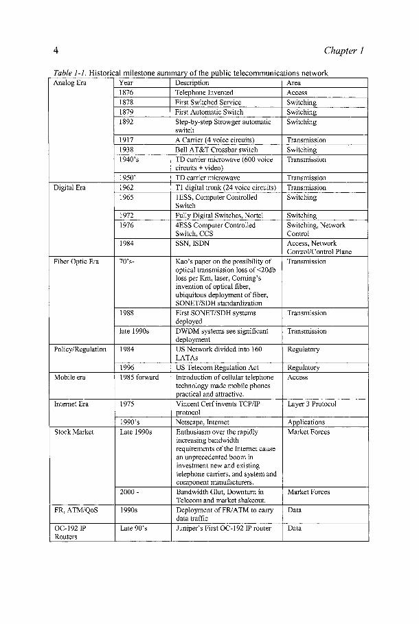
In this section, we examine transport networks from two differentviewpoints. In the first approach, transport networks can be broken downaccording to their geographical or functional scope. The second approach,which provides the outline for the remaining chapters in this book, is todecompose transport networks into the three logical planes; transport,management, and control. To begin the section, however, it is useful to havea brief historical review of the evolution of transport networks to set thediscussions in their proper context.
1 A favorite saying of Ray Simila, former manager of U.S. West's transmission equipmentevaluation laboratory who is still very active in the telecommunications field.
Chapter 1
Table 1-1. Historical milestone summary of the public telecommunications networkAnalog Era
Digital Era
Fiber Optic Era
Policy/Regulation
Mobile era
Internet Era
Stock Market
FR, ATM/QoS
OC-192IPRouters
Year1876187818791892
191719381940's
1950'19621965
19721976
1984
70's-
1988
late 1990s
1984
19961985 forward
1975
1990'sLate 1990s
2000-
1990s
Late 90's
DescriptionTelephone InventedFirst Switched ServiceFirst Automatic SwitchStep-by-step Strowger automaticswitchA Carrier (4 voice circuits)Bell AT&T Crossbar switchTD carrier microwave (600 voicecircuits + video)TD carrier microwaveTl digital trunk (24 voice circuits)1ESS, Computer ControlledSwitchFully Digital Switches, Nortel4ESS Computer ControlledSwitch, CCSSSN, ISDN
Kao's paper on the possibility ofoptical transmission loss of <20dbloss per Km, laser, Coming'sinvention of optical fiber,ubiquitous deployment of fiber,SONET/SDH standardizationFirst SONET/SDH systemsdeployedDWDM systems see significantdeploymentUS Network divided into 160LATAsUS Telecom Regulation ActIntroduction of cellular telephonetechnology made mobile phonespractical and attractive.Vincent Cerf invents TCP/IPprotocolNetscape, InternetEnthusiasm over the rapidlyincreasing bandwidthrequirements of the Internet causean unprecedented boom ininvestment new and existingtelephone carriers, and system andcomponent manufacturers.Bandwidth Glut, Downturn inTelecom and market shakeout.Deployment of FR/ATM to carrydata trafficJuniper's First OC-192 IP router
AreaAccessSwitchingSwitchingSwitching
TransmissionSwitchingTransmission
TransmissionTransmissionSwitching
SwitchingSwitching, NetworkControlAccess, NetworkControl/Control PlaneTransmission
Transmission
Transmission
Regulatory
RegulatoryAccess
Layer 3 Protocol
ApplicationsMarket Forces
Market Forces
Data
Data
1. INTRODUCTION TO TRANSPORT NETWORKS 5
1.2.1 Historical perspective
The history and milestones of the telecommunications networks issummarized in Table 1-1. The earliest transport network were point-to-pointcopper cables with separate wires dedicated to each voice channel. (Theswitching nodes were operators with manual patch panels.) Since this wasclearly an unscalable approach, it become important to introducemultiplexing so that multiple voice channels could be carried over the sameset of wires. Until the 1960s, when the first digital transmission systemswere introduced, the voice channels were transmitted as analog signals. Thefirst multiplexing technology was Frequency Division Multiplexing (FDM)since this was the most appropriate for carrying analog signals. Carryingthese analog FDM signals for long distances over copper wires wasunattractive since it required running cables through very difficult terrainand required frequent amplification to restore the signal level. Microwaveradio transmission provided the answer for many years in the long distancetransport networks.
When digital transmission technology was introduced in the early 1960s,it proved to be revolutionary. As those familiar with communicationssystems are aware, a digital signal can be regenerated such that if there areno bit errors, there will be no degradation to the signal regardless of howmany time the signal is regenerated2. In contrast, analog signals suffer adecrease in signal-to-noise ratio and some distortion at each point where thesignal is amplified. Also, the integrated circuit technology that was alsointroduced in the 1960s proved much amenable to building low-cost digitalcircuits than analog circuits. With the introduction of digital transmissiontechnology, the most appropriate multiplexing technology was TimeDivision Multiplexing (TDM). Digital TDM was used both on copper cablesystems and on microwave radio.
In North America, the digital hierarchy was defined by AT&T andreferred to as Digital Signal of level η in the hierarchy (DSw). The DS1signal carried 24 voice channels at a rate of 1.544 Mbit/s, the DS2multiplexed four DSls at a rate of 6.312 Mbit/s, and the DS3 multiplexedseven DS2s at a rate of 44.736 Mbit/s. The DSn hierarchy was commonlyreferred to as the asynchronous hierarchy. In other parts of the world, thehierarchy defined by the CCITT3 was adopted and referred to as the
This, of course, assumes that the signal doesn't accumulate too much jitter at eachregenerator.CCITT stands for International Telegraph and Telephone Consultative Committee. TheCCITT changed its name during the 1990s to International Telecommunications Union -Telecommunications Standardization Sector (ITU-T).

6 Chapter 1
plesiochronous digital hierarchy. The PDH signals are the 2.048 Mbit/ssignal that carries 30 voice channels, the 8.488 Mbit/s signal that multiplexesfour 2.048 Mbit/s signals, the 34.368 Mbit/s signal that multiplexes four8.488 Mbit/s signals, and the 139.264 Mbit/s signal that multiplexes four34.368 Mbit/s signals4.
The only integrated OAM&P capability with analog FDM systems wasthe inclusion of an orderwire channel in some of the signals. An orderwireis a dedicated, point-to-point voice channel that the crafts people at each ofthe orderwire channel could use for communications when they configuredor maintained that facility or equipment at either end of the channel. One ofthe characteristics of the DS/z and PDH hierarchies is that they had verylimited integrated OAM&P capability. The DS1 time-shared its framing bitto derive a CRC and its advanced implementations provide a 2 kbit/sOAM&P message channel. The 2.048 Mbit/s channel similarly time-sharedits framing byte to derive OAM&P channels. The higher rate signalstypically only included some type of error detection bits in the frame. Theresult was that OAM&P of the network tended to be somewhat laborintensive, and it was difficult to quantify the quality of service beingprovided to different subscribers (users). In the mid-1980s, it was estimatedthat over 70% of a telephone companies costs went to OAM&P with lessthan 10% going to new equipment. Clearly, reducing OAM&P costs was ahigh priority.
It was also true that providing new services typically took a long time.The long lead times included putting the infrastructure in place to enablethose services, but even with the infrastructure in place it would sometimestake weeks or even months before a service could be turned up for a newcustomer. Long provisioning times and lack of network flexibility thuslimited the carriers' ability to bring in new revenue.
Another key historical factor relating to OAM&P was the break-up of theBell System (AT&T). Now, a typical business connection would involvethree different carriers; namely the two local exchange carriers (LEC) andthe long distance interexchange carrier (IEC). If a problem existed on amulti-carrier connection, it became extremely important (under the threat oflaw suits from business customers who were losing revenue) for the carriersto determine whether or not the problem occurred in their network. Thissituation was a major driver toward more better, more accurate, and faster
4 These PDH signals are often referred to as E1-E4, respectively. The relatively new ITU-Tdesignation for the DSn and PDH signals are PI 1 = DS1, PI2 = El, P21 = DS2, P22 = E2,etc. In this book, the more familiar DS« and En designations are typically used. Both theDSn and PDH hierarchies have a level higher than the one shown here, but since these sawlimited deployment they are omitted.
1. INTRODUCTION TO TRANSPORT NETWORKS 7
methods for tracking the performance of connections and facilities, andbetter fault location and identification. A similar situation occurred in othercountries as the government owned carriers were privatized.
Around the same time as the Bell System break-up, fiber optic cableswere being deployed in transport networks. Fiber offered hugeimprovements in capacity and signal quality relative to copper cablesystems, and it was often easier to find right-of-way for the cables due to themuch smaller size of the optical cables. As the technology improved, itbecame feasible to begin replacing the microwave radios in the long distancenetwork with optical fibers5.
Fiber brought some new challenges, but it also offered some critical newopportunities. The early fiber optic systems were built on the existingDSTZ/PDH multiplexing approach, with each vendor typically using its ownproprietary multiplexing frame format for the higher rate signals. Hence,there was little economy of scale and almost no cases where differentvendors' equipment could interwork. This meant that at a carrier-to-carrierinterface, both carriers would have to agree to a common equipment vendorif they wanted an optical interconnection. The desire for a standardhierarchy for fiber optic signals was one of the primary drivers for thedevelopment of the SONET and SDH standards. Since this was a newstandard, one of the opportunities was to define a standard that wascompatible between North America and the PDH users. As seen in Chapter3, this objective was largely achieved. The other opportunity derived fromthe much higher bandwidth capabilities of the optical fiber. With opticaltransmission, it was now feasible to add a considerable amount of overheadbandwidth that could be used to greatly reduce the cost and improved thecapabilities of networks' OAM&P. The combination of the SONET/SDHOAM&P overhead capabilities and the growing availability of computerresources has revolutionized network management and opened thepossibility of more automated control of the network.
At this point in history, SONET/SDH forms the backbone of most of theworld's transport networks with computer-based network managementsystems being common. As discussed in the appropriate sections throughoutthis book, a number of potential future directions are being explored for nextgeneration telecommunications networks. One future direction will be anincreasing amount of wavelength-division multiplexing (WDM). WDM isalready seeing extensive deployment, and interestingly, is essentially areturn to an FDM technology (i.e., a wavelength can be regarded as a carrierfrequency). Another direction for transport networks is an increasingcapability for efficient, flexible data transport rather than just being
Sprint was the first major long distance carrier to convert to an all-fiber long haul network.
8 Chapter 1
optimized for voice traffic. At this time, the focus has been on addingtransport capabilities. Some carriers are promoting a migration to carryingand switching all traffic as data traffic rather than using TDM. Multi-Protocol Label Switching (MPLS) is expected to be the core technology inthese packet based networks. Voice signals can be packetized and carried asVoice over Internet Protocol (VoIP).
Another important future direction is and an increase in the ability forautomated or near-real-time control of the transport network through theintroduction of a control plane on top of the management plane as discussedin section 1.2.3. The control plane has the potential to allow much faster andmore flexible initiation of new services and modification of services as theyare being used. Chapter 9 contains extensive discussion of control planerelated aspects.
A historical aspect that can't be overlooked is the increased capability oftransport networks to recover from failures in the network. When individualfacilities carried relatively few channels, it was not cost-effective to providea redundant facility or bandwidth to carry the traffic in the event of a failurealong the working path. As more channels are multiplexed onto higher-ratesignals, it becomes increasingly important not to let a failure disrupt all ofthese channels. Some of the data traffic that is carried in modern networks isalso critical to protect (e.g., communications among air-traffic controllers,and corporate and military data traffic). SONET/SDH integrates some verypowerful automatic protection switching capabilities. A number of otherprotection and restoration options have become feasible due to the increasedcomputing capabilities of network nodes. Chapter 8 is devoted to this topic.
1.2.2 Classification by geography
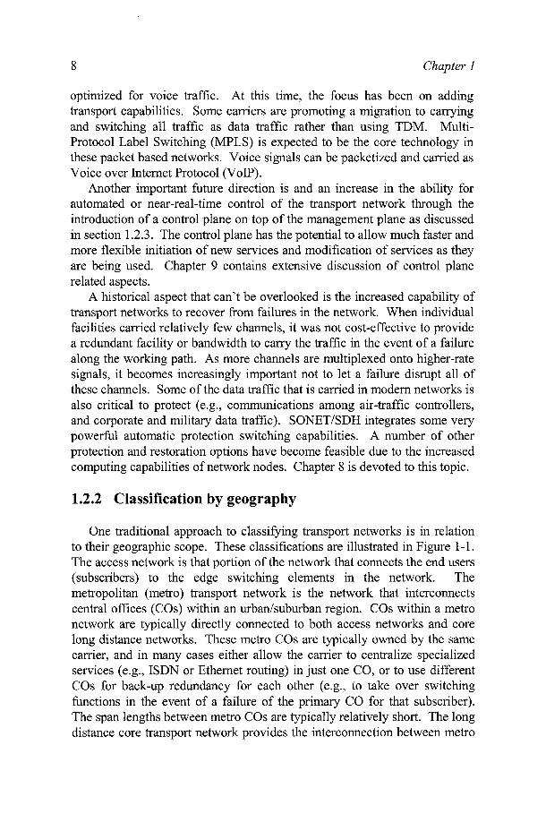
One traditional approach to classifying transport networks is in relationto their geographic scope. These classifications are illustrated in Figure 1-1.The access network is that portion of the network that connects the end users(subscribers) to the edge switching elements in the network. Themetropolitan (metro) transport network is the network that interconnectscentral offices (COs) within an urban/suburban region. COs within a metronetwork are typically directly connected to both access networks and corelong distance networks. These metro COs are typically owned by the samecarrier, and in many cases either allow the carrier to centralize specializedservices (e.g., ISDN or Ethernet routing) in just one CO, or to use differentCOs for back-up redundancy for each other (e.g., to take over switchingfunctions in the event of a failure of the primary CO for that subscriber).The span lengths between metro COs are typically relatively short. The longdistance core transport network provides the interconnection between metro
1. INTRODUCTION TO TRANSPORT NETWORKS 9
networks, smaller community COs, service providers (e.g., Internet), andregional or international gateways.
„Business,-•·••' customer Mobi
Residential customercustomer/ £
MetroTransport
/ \ Network
j^J Carrier Central Office
P| Digital Loop Carrier/Remote Multiplexer
^^ Local Loop (copper)
PON = Passive Optical Network
Figure 1-1. Illustration of a telecommunications network
Higher bandwidth technology typically sees its first deployment in thecore network since the longer facility lengths necessitate more efficient

10 Chapter 1
utilization of the facilities. The technology used in the core networks,however, typically eventually finds its way into the metro network as thecost of the technology decreases and the bandwidth needs of the metronetworks increase. From the management, craft training, and equipmentinventory perspectives, it is desirable to have as much commonality aspossible between the core and metro networks when they exist within thesame carrier. LECs typically have both metro networks and core networksto provide interconnection within their region. IECs also typically have bothmetro and core networks since they often deploy metro networks in order tomore efficiently reach their business/corporate subscribers.
Referring again to Figure 1-1, it can be seen that both metro and coretransport networks can consist of ring and mesh topologies. Rings havebecome increasingly popular since they provide inherent route diversity thatcan be exploited for protection switching. (See City 1 and upper portion ofthe core network.) Rings have also become increasingly popular in accessnetworks (e.g., City 3). Traffic routing on rings is also more straightforwardthan in arbitrary mesh networks. Ring topologies are not always convenient,however, due to such constraints as geography or having to use pre-existingright of ways6. Arbitrary mesh networks are constructed in order to useconvenient cable routings or, in some cases, allow more bandwidth-efficientprotection schemes. (See Chapter 8.) Transport networks often consist of amix of ring and mesh subnetworks, including interconnected rings.
Traditionally, a sharp distinction was drawn between transmission andswitching equipment. For the purposes of this book, however, transmissionand switching are both considered as part of the transport network. Theswitches provide the automatic routing of voice (or data) traffic, while thetransmission equipment handled the multiplexing and facility connections tocarry the traffic between the switches. For example, a voice switch is theequipment to which a subscriber's telephone is connected that does the digitcollection when the subscriber dials, and routes the call according to thenumber that was dialed. Typical transmission equipment includesSONET/SDH terminals. The distinction between transmission andswitching has continued to blur over the past 20 years. Transmissionnetworks have increasingly deployed digital crossconnect systems (DCSs)that perform the switching of subscribers' traffic between the various DCSinterfaces according to a provisioned route. (See Chapter 2 for a fulldiscussion on switching and crossconnect technology.) DCS-type
6 Of course, a ring can be laid out such that the fibers from different inter-node connectionsshare the same physical right of way or even the same cable. Such rings are calledcollapsed rings. Collapsed rings don't provide diverse fiber outing in the collapsedportion, and are hence vulnerable to a cable failure (e.g., due to a backhoe) in that region.
1. INTRODUCTION TO TRANSPORT NETWORKS 11
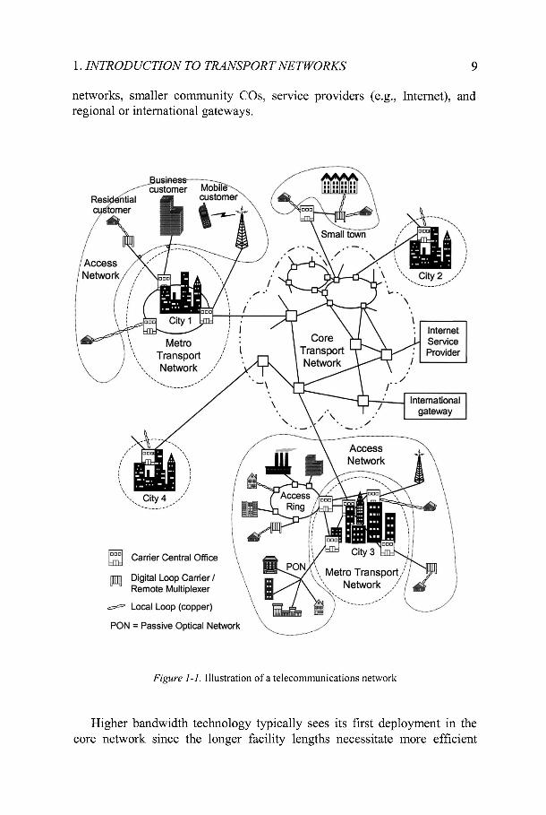
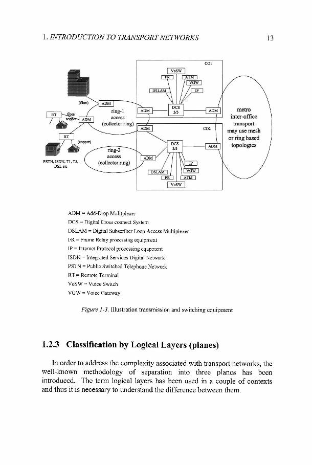
crossconnect capability has increasingly been integrated into add-dropmultiplexers (ADMs). As illustrated in Figure 1-2, an ADM has two high-speed multiplexed interfaces, each to a different NE. Lower-rate traffic(tributaries) can be added/removed to/from the data transiting the ADM ineither direction. ADMs are also typically capable of directly interconnectingtwo tributaries without that data appearing on one of the high-speedinterfaces.7 A network with switches, DCSs, and ADMs is illustrated inFigure 1-3. Rings nodes are typically ADMs, although they can also beDCSs, while mesh networks are typically constructed of DCSs.
Tributary interface (e.g., DS1, E1, DS3,lower-rate SONET/SDH)
Figure 1-2. Illustration of an Add-Drop Multiplexer (ADM)
7 This figure illustrates the main general functional blocks in an ADM. Differentimplementations have used a wide variety of approaches with respect to partitioning thesefunctions among the different printed circuit boards and the interconnections between thefunctional units.
12 Chapter 1
The distinction between a switch and a DCS/ADM has become a matterof how they are controlled rather than by their switching functions.Switches communicate with each other through a control plane in order toprovide the customer-requested connection. (Control planes are introducedin the next section and are discussed in detail in Chapter 9.) DCSs andADMs rely on provisioning from the network management system (i.e., themanagement plane that is introduced in the next section and discussed indetail in Chapters 5-7). Switches are very dynamic while crossconnects arerelatively static. This distinction is beginning to blur even further, however,as protocols are being developed to allow dynamic re-provisioning of DCSsand ADMs through the control plane. (Again, see Chapter 9.)
1. INTRODUCTION TO TRANSPORT NETWORKS 13
ring-lADM a C C e S S
(collector ring)
metrointer-officetransport
may use meshor ring based
topologies
ADM = Add-Drop Mulitplexer
DCS = Digital Cross connect System
DSLAM = Digital Subscriber Loop Access Multiplexer
FR = Frame Relay processing equipment
IP = Internet Protocol processing equpment
ISDN = Integrated Services Digital Network
PSTN = Public Switched Telephone Network
RT = Remote Terminal
VoSW = Voice Switch
VGW = Voice Gateway
Figure 1-3. Illustration transmission and switching equipment
1.2.3 Classification by Logical Layers (planes)
In order to address the complexity associated with transport networks, thewell-known methodology of separation into three planes has beenintroduced. The term logical layers has been used in a couple of contextsand thus it is necessary to understand the difference between them.
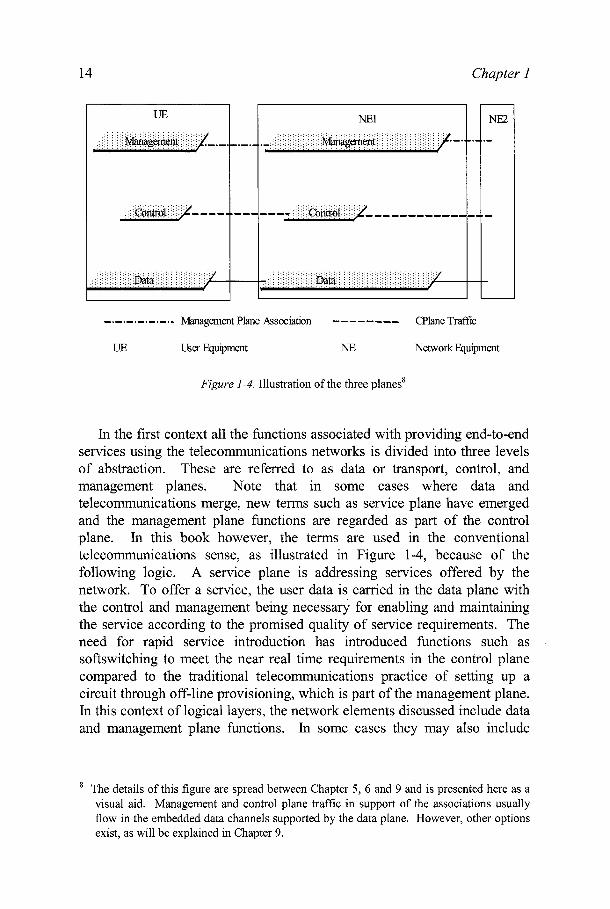
14 Chapter 1
UE NE1
—
NE2
Management Plane Association CPlane Traffic
UE User Equipment NE Network Equipment
Figure 1-4. Illustration of the three planes8
In the first context all the functions associated with providing end-to-endservices using the telecommunications networks is divided into three levelsof abstraction. These are referred to as data or transport, control, andmanagement planes. Note that in some cases where data andtelecommunications merge, new terms such as service plane have emergedand the management plane functions are regarded as part of the controlplane. In this book however, the terms are used in the conventionaltelecommunications sense, as illustrated in Figure 1-4, because of thefollowing logic. A service plane is addressing services offered by thenetwork. To offer a service, the user data is carried in the data plane withthe control and management being necessary for enabling and maintainingthe service according to the promised quality of service requirements. Theneed for rapid service introduction has introduced functions such assoftswitching to meet the near real time requirements in the control planecompared to the traditional telecommunications practice of setting up acircuit through off-line provisioning, which is part of the management plane.In this context of logical layers, the network elements discussed include dataand management plane functions. In some cases they may also include
The details of this figure are spread between Chapter 5, 6 and 9 and is presented here as avisual aid. Management and control plane traffic in support of the associations usuallyflow in the embedded data channels supported by the data plane. However, other optionsexist, as will be explained in Chapter 9.

1. INTRODUCTION TO TRANSPORT NETWORKS 15
control plane features discussed in G.771x series explained in Chapter 9.There are also control plane elements such as signaling control point,signaling switching point network elements that perform only these activities(e.g., setting up a call using an SS 7 network). The management planefunctions reside in the network elements and operations support systemsdiscussed below.
The second context in which logical layers is used in the book is indiscussing the management architecture in Chapter 5. The managementplane functions are separated into different logical layers to provide differentviews of the management information. Depending on the managementfunction and resources managed, different layers come into play.
1.2.4 Access networks and their relationship to transportnetworks
Although a full treatment of access networks is beyond the scope of thisbook, it is worthwhile commenting on several aspects of access networkshere that have a bearing on transport networks.
A very large portion of each LEC's capital investment is in the copperwires that connect to the subscribers through the access network. In order toreduce the amount (and length) of access network cable and reduce cablemaintenance, carriers increasingly deploy digital loop carrier (DLC) orremote multiplexing (RM) equipment. DLC and RM equipment connect to anumber of subscribers over relatively short copper connections andmultiplex their signals onto a shared facility (either copper or fiber) back tothe CO. A DLC is effectively a remote extension of the voice switch in theCO. RMs include remote digital subscriber line access multiplexers(DSLAMs) that provide DSL service to subscribers. The use of RMs isoften necessary in order to reduce the length of the copper connections to thesubscribers to a range that will support high-speed data services such asDSL. DLCs and RMs also have the advantage of placing performancemonitoring capabilities closer to the customer, which is often very valuablewhen subscribers use services with a guaranteed service level. The furtherdownstream the network reaches to end subscribers, however, the fewer thenumber of subscribers that can share that facility or equipment. Due to thisreduced sharing, the access facilities and equipment are very cost sensitive.
Access networks typically use transport equipment for connecting toDLCs, RMs and wireless network base stations, and also for dedicatedconnections to larger business subscribers. For example, many DLCs areconnected to SONET multiplexers in the same remote enclosure. Anotherexample is providing DS1, DS3, or SONET interfaces to subscribers from abusiness campus node with a SONET multiplexer providing the link back to
16 Chapter 1
the CO. In many cases, the access networks are deployed with aSONET/SDH ring topology in order to protect against facility or equipmentfailures. Chapter 8 discusses such protection switching. In a recentdevelopment, the IEEE 802.17 Resilient Packet Ring (RPR) technologyallows a convenient method for multiple subscribers (typically businesses) tohave efficient, flexible data access to SONET/SDH ring networks. RPR isone of the topics covered in Chapter 4. Carriers will typically try to usetransport equipment in their access networks whenever the equipment costsallow it, since this commonality can reduce their overall cost of training andequipment inventory. SONET is a prime example of a transport technologythat continues to migrate from the transport network to the access network.
One aspect in which the U.S. access network affects the transportnetwork has to do with federal government regulation. In order to encouragecompetition for local access, the Federal Communications Commission(FCC) requires the incumbent LECs (ILECs) to lease portions of their accessnetwork to competitive LECs (CLECs) at a discounted rate. The discountedrate allows the CLEC to provide the same services as the ILEC at acompetitive rate. The services, equipment, and facilities that the ILEC mustmake available to the CLEC are referred to as being unbundled. The natureof the unbundling regulations changes over time. The current regulationsinclude the requirement for the ILEC to provide DS/z access to subscribersregardless of whether they are carried over copper cable or are derived froma fiber optic multiplex system (e.g., carried over SONET through the accessnetwork). This gives DS1 and DS3 access connections an artificially lowercost for CLECs than equivalent SONET connections9. As noted in Chapter4, this situation can be especially important for the IECs and serviceproviders leasing access to their business subscribers through the ILECs.
Another aspect of the relationship between the access and transportnetworks is that the access network is often the primary bandwidthbottleneck in the overall network. The amount of traffic carried in the accessnetworks determines the bandwidth needs of the transport networks. Forlarger business customers, it is usually cost-effective to deploy a dedicatedhigh-speed fiber or copper facility from a CO or a remote fiber node to thebusiness office. The traffic from these connections can often be multiplexedwith other traffic in the access network as shown in the City 3 access ring ofFigure 1-1. For residential customers, however, it is very expensive toupgrade or replace the copper cables10 that connect them to the telephonenetwork in order to support broadband service. Meanwhile, there has been
9 ILECs are not required to unbundle their fiber-based interfaces and associated services.10 The copper wire connection to a subscriber is typically an unshielded twisted pair of wires.
This wire pair is often referred to as a loop (subscriber loop or local loop).
\. INTRODUCTION TO TRANSPORT NETWORKS 17
no driving application that motivates subscribers to pay high enough rates tojustify the network upgrade. Current technology such as DSL providesadequate speeds for today's applications such as Internet access andtelecommuting. So, while this bottleneck is gradually being removed forresidential and small business subscribers, it may take many years.
This bottleneck situation has led many in the telecommunicationsindustry to hunt for more cost-effective ways of providing higher bandwidthto residential and small business subscribers. The alternatives fall into fourbroad categories:
• Higher rates over the existing local subscriber loop• High-speed data connections through the cable TV network• Direct fiber connections to the home or near to the home (I.e., FTTx -
Fiber to the "x" where χ can be a home, curb, business, building, orequipment cabinet.)
• Wireless links
Achieving higher rates over the local loop means deploying remotemultiplexers (RMs) much closer to the subscribers in order to keep the looplengths short enough to allow the higher rates. Very high speed DSL(VDSL) promises rates high enough for video delivery over loops a fewhundred to a few thousand feet long. The main cost benefit to this approachis that it re-uses the copper loops. It is still expensive, however, to deploy allthe RMs to get close enough to the subscribers. The RMs are connected tothe CO through an optical fiber, which means that the each of the RMs needsa local connection for power.
The other existing infrastructure is the cable TV network. Originally,this network was developed for the downstream broadcast of analog videosignals. In order to support data services, it is being upgraded to provide anupstream as well as downstream data channels. The connection to thesubscriber homes is through a shared coaxial cable with cable modems usedby the subscribers for the data connection to the network. Since the coaxcable segments are shared by multiple subscribers, the data rate available toeach subscriber depends on how many subscribers are using that segment.There may be up to 2000 homes connected to the same segment. The DataOver Cable System Interface Specifications (DOCSIS™) protocol is used tocontrol the medium access for the data. The coax segments are connected tofiber nodes (FNs) that are in turn connected to hub nodes. The hubs areultimately connected to a head-end for their video signals or to serviceprovider networks for Internet connections. Due to this mix of coaxsegments and fiber, these networks are commonly revered to as hybridfiber/coax (HFC) networks. The FNs are analogous to the RMs and the hubs
18 Chapter 1
are analogous to either ADMs or DCSs in the telephone network. The maincost advantage of cable modems is the sharing of the coax segments and theinherently higher bandwidth capabilities of coax cable. The cost is similar tothe RM/VDSL telephone network approach. Higher rates per subscriberrequire fewer subscribers per segment, which means more FNs. While thisarchitecture is very good for residential subscriber connections, it is typicallynot very good for business subscribers who prefer dedicated bandwidth andprefer a non-shared access medium for security reasons. (Also, fewbusinesses have pre-existing connections to the cable TV network.)
The ultimate scenario for telephone and cable TV network providers is tohave a fiber optic connection to each subscriber. The fibers can offervirtually unlimited bandwidth to the subscribers. The main cost to fiberconnections is the components and circuitry to connect to the fibers.Consequently, passive optical networks (PONs) have been a focus ofconsiderable interest. In a PON, there is a single fiber connection at anoptical line terminal (OLT) in the CO, and that fiber branches out to multiplesubscriber-end optical network terminal units (ONUs) through a network ofpassive optical splitters. A time division multiple access (TDMA) protocolis typically used to multiplex data on the fiber tree.
There are two groups actively pursuing PON standards. The first is theFull Services Access Network (FSAN) forum. FSAN has developed astandard referred to as Broadband PON (BPON) that is based on ATMtechnology11. The BPON rates are 155 or 622 Mbit/s downstream (i.e., tothe subscriber) and 155 Mbit/s upstream. FSAN recently completed work ona Gigabit PON (GPON) that is based on a GFP-like format. (See Chapter 4for a full description of GFP. GPON uses modified header informationrelative to a normal GFP frame and allows fragmentation.) The GPON ratesare 2.4 or 1.2 Gbit/s downstream and 155 or 622 Mbit/s upstream. FSANhas brought its work to the ITU-T for publication with G.983 coveringBPPON and G.984 covering GPON. The other standards body working onPONS is the IEEE 802.3ah. Not surprisingly, these PONs are based onEthernet and are referred to as EPONs. EPONs support rates of 10 - 1000Mbit/s in both the upstream and downstream directions. BPON, GPON, andEPON each have their advantages and disadvantages. While NorthAmerican carriers have chosen the PONs from FSAN, there is considerableinterest in other regions in EPON (e.g., Japan and Korea) where forregulatory competitive reasons carriers need to make a clear distinctionbetween the POTS and data service access networks.
PONs can be very attractive for business customers since they provide alower cost network for broadband services than point-to-point fibers and
An ATM-based PON is commonly referred to as an ΑΡΟΝ.

\. INTRODUCTION TO TRANSPORT NETWORKS 19
they allow the ability to burst data at higher rates (i.e., approach the fullPON bandwidth) when the network is lightly loaded. Apart from the costissues, PONs have one technical issue that has been a major impediment. Amajor feature of the current telephone network is that the LEC providespower over the local loop to subscribers' phones. Since this telephonecompany provided power insures that the phones will still operate duringpower company outages, it is often referred to as lifeline phone service.Clearly this is not possible over an all-fiber network, so the telephonecompany must either provide an alternative, battery-backed power source,which is very expensive12, or the subscribers must take responsibility fortheir own power and maintain their own batteries. Perhaps the growingprevalence of mobile phones will make this a viable option at some point assubscribers become accustomed to idea of being responsible for their ownphone batteries. As discussed further below, a number of carriers arecounting on this.
The fourth alternative for broadband subscriber access had long beenconsidered the wildcard, but is now looking very promising. Thatalternative is wireless access. Previously, broadband wireless accessrequired a point-to-point microwave radio link from the subscriber to a basestation, with many of these systems requiring a line-of-sight clear pathbetween to two antennas. Here, each subscriber has its own radio channel.One common early system was the Local Multipoint Distribution System(LMDS). These systems were somewhat difficult to engineer and weresomewhat costly for many areas. Their main value was for businesscustomers. The Multi-channel Multipoint Distribution Systems (MMDS)addressed some of these shortcomings, but was still expensive for large-scale deployment. The radio technology that appears to be changing thewhole situation is IEEE 802.11. With 802.11, multiple subscribers can sharea single broadband radio channel. The statistical channel sharing means thatsubscribers will typically see very high throughput rates. The widespreaduse of 802.11 technology in LAN applications has driven the cost down to avery attractive point. The IEEE 802.16 technology extends some of the802.11 concepts to a metropolitan area. The main initial application for802.16 has been the backhaul of traffic from 802.11 base station sites tocentral switching sites (e.g., a CO), thus providing metropolitan areanetwork (MAN) connectivity between the 802.11 sites. Some business
12 The cost of maintaining batteries at each subscriber's home makes it a prohibitive optionfor the LECs. There have been some attempts to solve the problem be having a commonpower pedestal in the neighborhood that provides a battery-backed power feed to multiplehomes. While this is better, it still means a large number of batteries that need routinemaintenance and still requires maintaining a copper infrastructure.