Embed Size (px)
Citation preview

DatasheetNext Generation Self-contained DC-operated Sensors
• Economical photoelectric sensors for cost sensitive and high volume installations• Powerful and bright visible red emitter beam for easy alignment and set-up• Highly visible output and dual-function power and stability indicators• Wide operating temperature range: –40 °C to +70 °C (–40 °F to +158 °F)• Robust 250° adjustment potentiometer on select models• Stable detection in the presence of fluorescent lights for non through-beam
applications
WARNING: Not To Be Used for Personnel Protection
Never use this device as a sensing device for personnel protection. Doing so could lead to serious injury ordeath. This device does not include the self-checking redundant circuitry necessary to allow its use inpersonnel safety applications. A sensor failure or malfunction can cause either an energized or de-energizedsensor output condition.
Models
Emitter/Receiver Models 1
Model Range Output
S18-2NAEL-2M
Emitter
25 m (82 ft)
NoneS18-2NAEJ-2M 25 m (82 ft) with beam inhibit
S18-2NAES-2M 25 m (82 ft) with adjustment
S18-2VNRL-2M
Receiver
25 m (82 ft)Complementary NPN
S18-2VPRL-2M Complementary PNP
S18-2VNRS-2M25 m (82 ft) with adjustment
Complementary NPN
S18-2VPRS-2M Complementary PNP
Polarized Retroreflective Models 1
Model Range Output
S18-2VNLP-2M6 m (19.7 ft) with BRT-84 reflector
Complementary NPN
S18-2VPLP-2M Complementary PNP
S18-2VNLPC-2M6 m (19.7 ft) with BRT-84 reflector, with adjustment
Complementary NPN
S18-2VPLPC-2M Complementary PNP
Retroreflective Models 1
Model Range Output
S18-2VNLV-2M7.5 m (24.6 ft) with BRT-84 reflector, with adjustment
Complementary NPN
S18-2VPLV-2M Complementary PNP
1 Integral 2 m (6.5 ft) unterminated cable models are listed.• To order the 9 m (30 ft) PVC cable model, add the suffix "9M" to the model number. For example, S18-2VNDL-9M.• To order the 4-pin M12/Euro-style integral quick disconnect model, add the suffix "Q8" to the model number. For example, S18-2VNDL-Q8.• To order the 150 mm (6 in) PVC cable model with a 4-pin M12/Euro-style quick disconnect, add the suffix "Q5" to the model number. For
example, S18-2VNDL0Q5.• To order the 150 mm (6 in) PVC cable model with a 4-pin M8/Pico-style quick disconnect, add the suffix "Q3" to the model number. For example,
S18-VNDL-Q3.
S18-2 Plastic 18 mm Barrel Sensors
Original Document170670 Rev. J
1 October 2018
170670

Diffuse Models 1
Model Range Output
S18-2VNDL-2M750 mm (29.5 in) with adjustment
Complementary NPN
S18-2VPDL-2M Complementary PNP
S18-2VNDS-2M300 mm (11.8 in) with adjustment
Complementary NPN
S18-2VPDS-2M Complementary PNP
Fixed Field Models
Model Range Output
S18-2VNFF30-2M30 mm
Complementary NPN
S18-2VPFF30-2M Complementary PNP
S18-2VNFF50-2M50 mm
Complementary NPN
S18-2VPFF50-2M Complementary PNP
S18-2VNFF75-2M75 mm
Complementary NPN
S18-2VPFF75-2M Complementary PNP
S18-2VNFF100-2M100 mm
Complementary NPN
S18-2VPFF100-2M Complementary PNP
S18-2VNFF150-2M150 mm
Complementary NPN
S18-2VPFF150-2M Complementary PNP
S18-2VNFF200-2M200 mm
Complementary NPN
S18-2VPFF200-2M Complementary PNP
Installing the S18-2 Sensor
Amber LED
Amber LEDGreen LED
Gain adjustment
Figure 1. S18-2 Features and Installation
To install the S18-2 Sensor:
1. Align the sensor as required for the application.For the most sensitive object detection, align thesensor so that the objects move across thesensor's axis.
2. Secure the sensor to a bracket.3. Wire sensor as shown in the wiring diagrams.4. Adjust the gain adjuster (sensitivity pot) if
necessary.
Wiring Diagrams
Emitter
10-30V dc
–
+1
3
Emitter with Active High BeamInhibit
10-30V dc−
+1
3
4 10-30V dc
Complementary NPN
10-30V dc–
+1
3
2
4 Load
Load
Complementary PNP
10-30V dc–
+1
3
2
4 Load
Load
Note: Open lead wires must be connected to a terminal block.
S18-2 Plastic 18 mm Barrel Sensors
2 www.bannerengineering.com - Tel: +1-763-544-3164 P/N 170670 Rev. J

Specifications
Supply Voltage10 V dc to 30 V dc for ambient temperature ≤ 55 °C10 V dc to 24 V dc for ambient temperature > 55 °C
Supply Current (Exclusive of Load Current)Diffuse: 16 mAOpposed Mode Emitters: 17 mAOpposed Mode Receivers: 8 mARetroreflective and Polarized Retroreflective: 16 mAFixed Field: 22 mA
Output Response TimeResponse is independent of signal strengthOpposed models: 1.5 milliseconds ON, 1 millisecond OFFRetro, Polarized Retro, and Diffuse models: 1.5 milliseconds ON,0.75 milliseconds OFFFixed Field models: 2 milliseconds ON, 2 milliseconds OFFDelay on Power-up: 100 milliseconds; outputs do not conductduring this time
Output Protection CircuitryProtected against false pulse on power-up and continuous shortcircuit of outputs. Short circuit protection at elevated temperaturemay require a power cycle to reset.
Supply Protection CircuitryProtected against reverse polarity and transient voltages
Output Rating≤ 50 mA total current for ambient temperatures > 55 °C≤ 100 mA total current through both outputs ≤ 55 °COFF-State Leakage Current: < 50 µA at 30 V dcON-State Saturation Voltage: < 1.5 V at 10 mA; < 3.0 V at 100 mA
Output ConfigurationComplementary PNP or NPN by model number
Emitter LEDVisible Red
RepeatabilityRepeatability is independent of signal strengthOpposed models: 170 microsecondsRetro, Polarized Retro, and Diffuse models: 100 microsecondsFixed Field models: 200 microseconds
AdjustmentsDiffuse (DL, DS), Emitter (ES), Receiver (RS), PolarizedRetroreflective (LPC), Retroreflective (LV) models: Single turnsensitivity (gain) adjustment potentiometerEmitter Beam Inhibit (EJ) models: Tie black wire to 10 to 30 V dc forbeam inhibit
ConstructionHousing, connector, gain pot driver: ABSFront window: PMMAIndicator windows: Clear ABSMounting nuts: 30% glass filled PBT
IndicatorsThree LEDs (1 green, 2 amber)Green solid: indicates power applied and sensor readyGreen flashing: indicates marginal sensing signalAmber solid: indicates Pin 4 (black wire) output conducting
Vibration and Mechanical ShockAll models meet Mil. Std. 202F requirements. Method 201A(Vibration; frequency 10 to 60 Hz, max., double amplitude 0.06 inacceleration 10G). Method 213B conditions H&I (Shock: 75G withunit operating; 100G for non-operation)
Operating Conditions–40 °C to +70 °C (–40 °F to +158 °F)95% at +50 °C maximum relative humidity (non-condensing)
Environmental RatingIEC IP67
Certifications
Class 2 power ; ULEnvironmental Rating: Type 1
Required Overcurrent Protection
WARNING: Electrical connections must bemade by qualified personnel inaccordance with local and nationalelectrical codes and regulations.
Overcurrent protection is required to be provided by end productapplication per the supplied table.Overcurrent protection may be provided with external fusing or viaCurrent Limiting, Class 2 Power Supply.Supply wiring leads < 24 AWG shall not be spliced.For additional product support, go to www.bannerengineering.com.
Supply Wiring(AWG)
Required Overcurrent Protection (Amps)
20 5.0
22 3.0
24 2.0
26 1.0
28 0.8
30 0.5
S18-2 Plastic 18 mm Barrel Sensors
P/N 170670 Rev. J www.bannerengineering.com - Tel: +1-763-544-3164 3
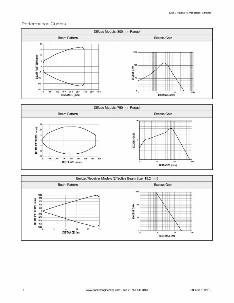
Performance Curves
Diffuse Models (300 mm Range)
Beam Pattern Excess Gain
50 10 0 15 0 20 0 25 0 30 0 35 0 40 0DISTANCE (mm)
BEAM
PAT
TERN
(mm
)
0−20
−15
−10
−5
0
5
10
15
20
DISTANCE (mm)
EXCE
SS G
AIN
11
10 100 1000
10
100
1000
Diffuse Models (750 mm Range)
Beam Pattern Excess Gain
- 15
- 10
- 5
0
5
10
15
0 100 200 300 400 500 600 700 800
BEAM
PAT
TERN
(mm
)
DISTANCE (mm)1
10
100
1 10 100 1000
EXCE
SS G
AIN
DISTANCE (mm)
Emitter/Receiver Models (Effective Beam Size: 15.2 mm)
Beam Pattern Excess Gain
- 1000- 800- 600- 400- 200
0200400600800
1000
0 5 10 15 20 25
BEAM
PAT
TERN
(mm
)
DISTANCE (m)1
10
100
1000
0.1 1 10 100
EXCE
SS G
AIN
DISTANCE (m)
S18-2 Plastic 18 mm Barrel Sensors
4 www.bannerengineering.com - Tel: +1-763-544-3164 P/N 170670 Rev. J

Polarized Retroreflective Models
Beam Pattern Excess Gain
- 60
- 40
- 20
0
20
40
60
0 1 2 3 4 5 6
BEAM
PAT
TERN
(mm
)
DISTANCE (m)
DISTANCE (m)
EXCE
SS G
AIN
0.01 0.1 1 101
10
100BRT-92x92CBRT-84BRT-60x40CBRT-40x19ABRT-60x40IPBRT-THG-2-100
Retroreflective Models
Beam Pattern Excess Gain
DISTANCE (m)
BEAM
PAT
TERN
(mm
)
0 1 2 3 4 5 6 7 8-80
-60
-40
-20
0
20
40
60
80
1
10
100
0.01 0.1 101DISTANCE (m)
EXCE
SS G
AIN
BRT-92x92CBRT-84BRT-60x40CBRT-40x19ABRT-60x40IPBRT-THG-2-100
S18-2 Plastic 18 mm Barrel Sensors
P/N 170670 Rev. J www.bannerengineering.com - Tel: +1-763-544-3164 5

Fixed Field Models - Excess Gain
Target for Excess Gain Curves use a 90% Reflective White Card
DISTANCE (mm)
EXCE
SS G
AIN
11
10
10
100
100
1000
1000
S18-2FF30
Emitter Image Size: 4.0 mm square at 15 mm and 3.5 mm square at 30mm
18% Gray Test Card: Cutoff distance will be 98% of value shown
6% Black Test Card: Cutoff distance will be 95% of value shown
DISTANCE (mm)
EXCE
SS G
AIN
11
10
10
100
100
1000
1000
S18-2FF50
Emitter Image Size: 4 mm square at 25 mm and 3 mm square at 50 mm
18% Gray Test Card: Cutoff distance will be 98% of value shown
6% Black Test Card: Cutoff distance will be 95% of value shown
DISTANCE (mm)
EXCE
SS G
AIN
11
10
10
100
100
1000
1000
S18-2FF75
Emitter Image Size: 4.5 mm square at 37 mm and 4.0 mm square at 75mm
18% Gray Test Card: Cutoff distance will be 98% of value shown
6% Black Test Card: Cutoff distance will be 95% of value shown
DISTANCE (mm)
EXCE
SS G
AIN
11
10
10
100
100
1000
1000
S18-2FF100
Emitter Image Size: 4.5 mm square at 50 mm and 4.5 mm square at100 mm
18% Gray Test Card: Cutoff distance will be 95% of value shown
6% Black Test Card: Cutoff distance will be 90% of value shown
S18-2 Plastic 18 mm Barrel Sensors
6 www.bannerengineering.com - Tel: +1-763-544-3164 P/N 170670 Rev. J

Fixed Field Models - Excess Gain
Target for Excess Gain Curves use a 90% Reflective White Card
DISTANCE (mm)
EXCE
SS G
AIN
1 10 100 10001
10
100
1000
S18-2FF150
Emitter Image Size: 5 mm square at 75 mm and 8 mm square at 150mm
18% Gray Test Card: Cutoff distance will be 90% of value shown
6% Black Test Card: Cutoff distance will be 70% of value shown
DISTANCE (mm)
EXCE
SS G
AIN
11
10 100 1000
10
100
1000
S18-2FF200
Emitter Image Size: 5 mm square at 100 mm and 8 mm square at 200mm
18% Gray Test Card: Cutoff distance will be 85% of value shown
6% Black Test Card: Cutoff distance will be 60% of value shown
Dimensions
QD ModelsCable Models64 mm[2.52”]
45.3 mm[1.78”]
13.1 mm[0.51”]
M18 x 1 16.7 mm[0.66”]
M12 x 1
73 mm[2.87”]
63.5 mm[2.50”]
M18 x 1 - 6gKnurled Nut (2)
Maximum Torque: 2.3 N∙m (20 in-lbs)
16.3 mm dia[0.64”]
All measurements are listed in millimeters [inches], unless noted otherwise.
Accessories
CordsetsAll measurements are listed in millimeters, unless noted otherwise.
S18-2 Plastic 18 mm Barrel Sensors
P/N 170670 Rev. J www.bannerengineering.com - Tel: +1-763-544-3164 7

4-Pin Threaded M12/Euro-Style Cordsets
Model Length Style Dimensions Pinout (Female)
MQDC-406 1.83 m (6 ft)
Straight
44 Typ.
ø 14.5M12 x 1
2
34
1
1 = Brown2 = White3 = Blue4 = Black
MQDC-415 4.57 m (15 ft)
MQDC-430 9.14 m (30 ft)
MQDC-450 15.2 m (50 ft)
MQDC-406RA 1.83 m (6 ft)
Right-Angle
32 Typ.[1.26"]
30 Typ.[1.18"]
ø 14.5 [0.57"]M12 x 1
MQDC-415RA 4.57 m (15 ft)
MQDC-430RA 9.14 m (30 ft)
MQDC-450RA 15.2 m (50 ft)
4-Pin Threaded M8/Pico-Style Cordsets
Model Length Style Dimensions Pinout (Female)
PKG4M-2 2 m (6.56 ft)
Straight ø 9.5
35 Typ.
M8 x 1
43 1
2
1 = Brown2 = White3 = Blue4 = Black
PKG4M-5 5 m (16.4 ft)
PKG4M-9 9 m (29.5 ft)
PKW4M-2 2 m (6.56 ft)
Right Angle
ø 9.5
28 Typ.
20 Typ.
M8 x 1
PKW4M-5 5 m (16.4 ft)
PKW4M-9 9 m (29.5 ft)
Apertures
Model Units Aperture Description Product
AP18SCN 3Kit includes round apertures of 0.5 mm (0.02 in), 1.0 mm (0.04 in), and2.5 mm (0.10 in) diameter.
AP18SRN 3Kit includes rectangular apertures of 0.5 mm (0.02 in), 1.0 mm (0.04 in),and 2.5 mm (0.10 in) wide. Each kit also includes a thread-on housing,Teflon® FEP® lens, and o-ring.
APG18S 1Kit with glass lens to protect plastic sensor lens from chemicalenvironments and weld splatter damage.
S18-2 Plastic 18 mm Barrel Sensors
8 www.bannerengineering.com - Tel: +1-763-544-3164 P/N 170670 Rev. J
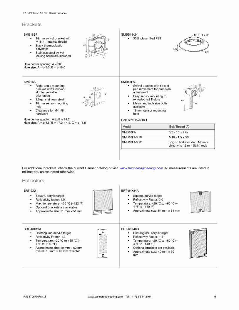
Brackets
SMB18SF• 18 mm swivel bracket with
M18 × 1 internal thread• Black thermoplastic
polyester• Stainless steel swivel
locking hardware included
B
A
51
42
25
Hole center spacing: A = 36.0Hole size: A = ø 5.3, B = ø 18.0
SMBS18-2-1• 30% glass-filled PBT
M18 - 1 x 6G
4.5ø28
SMB18A• Right-angle mounting
bracket with a curvedslot for versatileorientation
• 12-ga. stainless steel• 18 mm sensor mounting
hole• Clearance for M4 (#8)
hardware
30
41
46
A BC
Hole center spacing: A to B = 24.2Hole size: A = ø 4.6, B = 17.0 × 4.6, C = ø 18.5
SMB18FA..• Swivel bracket with tilt and
pan movement for precisionadjustment
• Easy sensor mounting toextruded rail T-slots
• Metric and inch size boltsavailable
• 18 mm sensor mountinghole
66
69A
B
Hole size: B=ø 18.1
Model Bolt Thread (A)
SMB18FA 3/8 - 16 × 2 in
SMB18FAM10 M10 - 1.5 × 50
SMB18FAM12 n/a; no bolt included. Mountsdirectly to 12 mm (½ in) rods
For additional brackets, check the current Banner catalog or visit www.bannerengineering.com. All measurements are listed inmillimeters, unless noted otherwise.
Reflectors
BRT-2X2
• Square, acrylic target• Reflectivity factor: 1.0• Max. temperature: +50 °C (+122 ºF)• Optional brackets are available• Approximate size: 51 mm × 51 mm
BRT-84X84A
• Square, acrylic target• Reflectivity Factor: 2.0• Temperature: –20 °C to +60 °C (–
4 °F to +140 °F)• Approximate size: 84 mm × 84 mm
BRT-40X19A• Rectangular, acrylic target• Reflectivity Factor: 1.3• Temperature: –20 °C to +60 °C (–
4 °F to +140 °F)• Approximate size: 19 mm × 60 mm
overall; 19 mm × 40 mm reflector
BRT-60X40C• Rectangular, acrylic target• Reflectivity Factor: 1.4• Temperature: –20 °C to +60 °C (–
4 °F to +140 °F)• Optional brackets are available• Approximate size: 40 mm × 60
mm
S18-2 Plastic 18 mm Barrel Sensors
P/N 170670 Rev. J www.bannerengineering.com - Tel: +1-763-544-3164 9
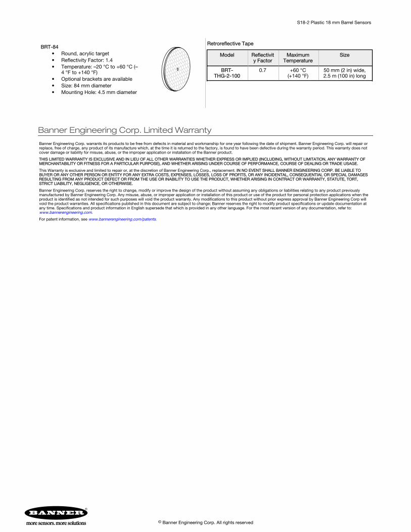
BRT-84• Round, acrylic target• Reflectivity Factor: 1.4• Temperature: –20 °C to +60 °C (–
4 °F to +140 °F)• Optional brackets are available• Size: 84 mm diameter• Mounting Hole: 4.5 mm diameter
Retroreflective Tape
Model Reflectivity Factor
MaximumTemperature
Size
BRT-THG-2-100
0.7 +60 °C(+140 °F)
50 mm (2 in) wide,2.5 m (100 in) long
Banner Engineering Corp. Limited Warranty
Banner Engineering Corp. warrants its products to be free from defects in material and workmanship for one year following the date of shipment. Banner Engineering Corp. will repair orreplace, free of charge, any product of its manufacture which, at the time it is returned to the factory, is found to have been defective during the warranty period. This warranty does notcover damage or liability for misuse, abuse, or the improper application or installation of the Banner product.
THIS LIMITED WARRANTY IS EXCLUSIVE AND IN LIEU OF ALL OTHER WARRANTIES WHETHER EXPRESS OR IMPLIED (INCLUDING, WITHOUT LIMITATION, ANY WARRANTY OFMERCHANTABILITY OR FITNESS FOR A PARTICULAR PURPOSE), AND WHETHER ARISING UNDER COURSE OF PERFORMANCE, COURSE OF DEALING OR TRADE USAGE.
This Warranty is exclusive and limited to repair or, at the discretion of Banner Engineering Corp., replacement. IN NO EVENT SHALL BANNER ENGINEERING CORP. BE LIABLE TOBUYER OR ANY OTHER PERSON OR ENTITY FOR ANY EXTRA COSTS, EXPENSES, LOSSES, LOSS OF PROFITS, OR ANY INCIDENTAL, CONSEQUENTIAL OR SPECIAL DAMAGESRESULTING FROM ANY PRODUCT DEFECT OR FROM THE USE OR INABILITY TO USE THE PRODUCT, WHETHER ARISING IN CONTRACT OR WARRANTY, STATUTE, TORT,STRICT LIABILITY, NEGLIGENCE, OR OTHERWISE.
Banner Engineering Corp. reserves the right to change, modify or improve the design of the product without assuming any obligations or liabilities relating to any product previouslymanufactured by Banner Engineering Corp. Any misuse, abuse, or improper application or installation of this product or use of the product for personal protection applications when theproduct is identified as not intended for such purposes will void the product warranty. Any modifications to this product without prior express approval by Banner Engineering Corp willvoid the product warranties. All specifications published in this document are subject to change; Banner reserves the right to modify product specifications or update documentation atany time. Specifications and product information in English supersede that which is provided in any other language. For the most recent version of any documentation, refer to: www.bannerengineering.com.
For patent information, see www.bannerengineering.com/patents.
S18-2 Plastic 18 mm Barrel Sensors
© Banner Engineering Corp. All rights reserved