Embed Size (px)
Citation preview

NEW WORLD RECORD
Bang Na Expressway,Bangkok, Thailand World’sLongest Bridge and LargestPrecasting Operation
Christian Brockmann,Prof. - Dip!. - Ing.University of Applied SciencesBremen, GermanyFormerly, Project Manageriv BBCDBangkok, Thailand
The new $1 billion Bang Na Expressway in Bangkok, Thailand, is not
only the longest bridge in the world, but also represents the largest
precasting operation ever carried out. The all-precast, prestressed
concrete superstructure has a total length of 55 km (34 miles). This
gigantic project provides an important link in the transportation
system around Bangkok and is expected to play a major role in the
commercial development of Southeast Thailand. The design solution
was to use precast segmental, span-by-span construction. The box
girders were match-cast and post-tensioned in place with dry joints
and external longitudinal tendons. This article presents the design-
build contract, describes the design features of the bridge, discusses
the construction techniques used in the project, and gives the details
of the precasting operation.
Horst Rogenhofer, Dr. - Ing.Bilfinger + Berger BauaktiengesellschaftInternational DivisionWiesbaden, Germany
Asof January 2000, the new $1
billion, 55 km (34 miles) longBang Na Expressway (BNE) in
Bangkok, Thailand, has earned the
right for entry into the Guinness Book
of Records as the longest bridge in theworld (see Fig. 1). This project is also
the largest precasting job ever under
taken. In breaking the record, the BNEproject surpasses in length and size thebridge crossing Lake Pontchartrain,Louisiana, in the United States (see
footnote).The elevated expressway built on
top of an at-grade highway for its en
tire length, stretches from the eastern
edge of Bangkok to the city of Chon
Bun. Conceived by the Expresswayand Rapid Transit Authority of Thai
land (ETA), BNE will form a majorelement of an extended and intercon
nected system of expressways in the
greater Bangkok area. With the BNE
Editor’s Note: completed in 1956, Lake Pontchar
train causeway, near New Orleans, Louisiana, is 38
km (23.8 miles) long. An all-precast prestressed con
crete structure, it was constructed in 12 months, a
major accomplishment at the time. The precast com
ponents were fabricated on Site using the long line pre
stressing method. The superstructure consists of 17 m
(56 ft) precast concrete sections composed of five par
allel girders supporting a deck slah, all cast monolithi
cally. The girders were supported on pile caps resting
on hollow cylinder piles. Today, after 44 years in ser
vice, the Lake Pontchartrain Causeway is still operat
ing satisfactorily.
26 PCI JOURNAL
a
a• —
a
1L—zz—z:
,—
project, ETA intends to facilitate theindustrial development of SoutheastBangkok and to connect the plannedSecond International Airport as wellas to connect the deep-water harborwith the city. Another reason for theexpressway is to alleviate traffic congestion in and around Bangkok.
The purpose of this article is to present the design-build contract, describe the design features of thebridge, discuss the construction techniques used in the project, and givethe details of the precasting operation.
DESIGN-BUILD CONTRACTIn June 1995, a contract was signed
between ETA and Joint VentureBBCD under the sponsorship of Bilfinger + Berger with Ch. Kamchang PLCas the important local partner. Thecontract covered 55 km (34 miles) ofelevated expressway together with anadditional 40 km (25 miles) of ramps
and intersections for a total deck areaof 1,900,000 m2 (20,400,000 sq ft).The agreement stipulated the projectwould be completed within 3’/2 years.
The BNE contract was broken downinto eight phases with each phase having a specific completion date. Thereason for this requirement is that theexpressway is a toll facility and, therefore, there was a financial incentive inmeeting the schedule so that eachcompleted section could be opened totraffic and start collecting toll fees.The entire project was stipulated to becompleted by January 2000.
Because of the extremely short construction period, the design phase hadto be completed quickly. This includedsoil investigations and foundation design, bridge alignment and geometry,structural design of the columns andsuperstructure, preparation of shopdrawings, lighting, traffic control, andtoll facilities. Also, a very large precasting yard had to be established.
In essence, this was a lump-sum design-build contract for the turnkeycompletion of the project. Thus, thestart of construction had to overlap theongoing design. In addition, JointVenture BBCD, under the contract,had to finance the project until completion. The total cost of planning, designing, constructing.and financing theproject was approximately $1 billion.
DESIGN FEATURESOF PROJECT
The BNE was constructed throughout its entire length on top of the center and outside medians of the existing at-grade Highway 34 (see Fig. 2),where by contract the traffic mustflow without interruption at a speedof 80 km/h (50 miles per hour). TheDepartment of Highways is currentlyupgrading Highway 34 and the twoprojects had to be carried out simultaneously over the same route. IV
V..
V , •.
V VV ‘V
——
Fig. 1. Overview of the BNE project in Bangkok, Thailand, completed in January 2000.
January-February 2000 27

BBCD facilitated the coordinationbetween the two projects.
During the planning and biddingphases of the project, JV BBCD compared an I-beam cast-in-place deckslab alternate with a precast segmentalsolution. It became apparent that segmental construction provided a moreefficient, faster and more economicalsolution than the first alternate. Production, handling and hauling of seg
ments, speed of construction, and pricing of units were all superior to anyother method.
At the same time, the box girder solution provides for an aestheticallypleasing structure. Also, the attractiveshape of the main line is highly influenced by the slender design of the boxgirder (see Fig. 3), which has a maximum span of 44.4 m (146 ft). The specific solution, then, was to use precast
segmental span-by-span constructionto build the elevated bridge. The boxgirders were match cast and when inplace had dry joints. The longitudinalpost-tensioning tendons were externalto the box Section. Adding to the aesthetics are H-shaped columns whichsupport the superstructure.
The main structure is a 27 m (89 ft)wide box girder spanning on average42 m (138 ft) between single-columnbents. The bents have a unique H-shape which was conceived to facilitate construction and to enhance overall aesthetics.
The expressway has two 13 m (43ft) wide roadways with three trafficlanes each, supported by the boxgirder. This exceptionally wide boxgirder is comprised of a single cell(i.e., only two webs) with diagonalstruts to support the long span of thetop slab between the webs. Each precast segment weighs approximately 85tonnes (94 tons).
The expressway has 36 ramps, allelevated, including 10 ramps, whichlead into major interchanges. The 26typical ramps are located symmetrically about the centerline of the expressway in pairs and lead from the elevated bridge to the frontage road ofthe existing highway below. Wideningof the main line structure to accommodate accelerationldeceleration lanes isaccomplished by using multiple boxgirders connected at the wing tips andsupported on precast segmental portalframes spanning the roadway below.
Note that there is a clearance abovethe existing highway of approximately14 m (46 ft). This space allows theconstruction of elevated U-turn rampsover the existing highway but belowthe new viaduct.
Two elevated toll plaza structuresare included in the project, one at eachend. These 80 m (262 ft) wide structures support up to 12 toll booths atthe exits in addition to toll surveillance facilities. This unusually largeincrease in structure width is accommodated by a similar approach as thewidening for the ramps. Up to six boxgirders are connected at the wing tipsand supported on precast segmentalportal frames.
An essential ingredient for the success of the BNE project was the estabFig. 3. Main line span of 44.40 m (146 ft).
28 PCI JOURNAL
lishment of an efficient precastingyard, which became the largest plantever assembled in the world. A totalof 40,000 segments, of varying proportions, were fabricated. The quantity and rate of production for boxgirders was one of the highest everachieved. Approximately 60 percentof the overall concrete requirementsfor the project were used in the yardfor the segments which were cast incarefully planned and always repetitive sequences in order to increase thespeed of fabrication and quality ofproduct. More details on the precasting operation will be given later on inthis article.
The technology of precast segmental construction, and particularly span-by-span construction, was pioneeredby Jean Muller and the firm he heads,Jean Muller International. Segmentalconstruction with external post-tensioning and dry joints has been implemented especially by Bilfinger +
Berger, Germany, on many bridgeprojects in Southeast Asia, Africa andAustralia. The principles used on theBNE project have been achieved before but never on such a giganticscale. For more information on segmental construction and on this project, see Refs. 1 to 7.
CONSTRUCTIONTECHNIQUES
This section describes the variousstructural elements and techniquesused in constructing the substructureand superstructure of the elevatedbridge.
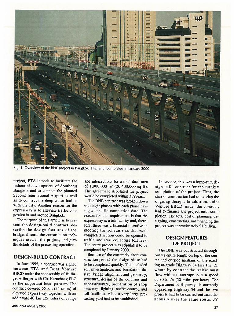
Foundation of Main Line
The city of Bangkok is situated inthe delta of the Menam Chao PhrayaRiver. The underlying soil can be simply classified as a three-layer model,namely, soft clay, stiff clay, and sand.It was, therefore, necessary to transferall loads to the sand layer.
For the BNE project, 800 mm (31.5in.) diameter precast spun piles, with awall thickness of 120 mm (4.72 in.),were used. The piles are in general 30m (98 ft) long. They are composed oftwo sections which are welded together to ensure the transfer of tensionand compression forces (see Fig. 4).
Typically, 16 piles are necessary totransfer the loads from the main linecolumns into the sand layer. In orderto produce the spun piles, a specialplant had to be built with sufficient capacity to manufacture the 900,000 m(2,953,000 ft) of piles required for theproject.
Fig. 4. Pile foundation.
Fig. 5. Mainline column with superstructure.
The difficulties in driving the pileswere due to the very soft consistencyof the upper clay layer [12 to 20 m (39to 66 ft) in thickness] which does notprovide any horizontal support for thepiles. The heaving pressure of the cohesive soil during pile driving cancause a displacement of more than 1 m
Idriven piles0800mmprestressedconcrete
soft clay
hard ólaS,
I I
sand, bearing stratum
welded/.
joint
30rn
January-February 2000 29

(3.3 ft). Thus, the speed of construction was often impeded by soil profiles comprising five to seven intermittent layers of clay and sand.
The loads transmitted by thecolumns are transferred to the pilesthrough a pile cap of 2.5 m (8.2 ft)thickness. The top of these pile caps isalways below the flow line of thedrainage in the center and outer medians of Highway 34.
Main Columns
The main line columns are H-shaped and display a slender light appearance. The H widens from its baseat the pile cap to the top so that theoutside corners are gracefully curved(see Fig. 5). The architectural designalso serves a structural function.
The columns are located in theopen drainage area of the center median of Highway 34 and reduce thesection of this free flow channel by aminimum amount. In the erection ofthe superstructure, an underslunggirder is used which moves throughthe upper arms of the column. Sincethere is no cross-beam, the launchingis simplified.
The superstructure is placed on inclined elastomeric bearings in order toavoid moments from load transfer between the box girder and columnsunder symmetrical loads. This requires very tight construction tolerances because the planes of the bearings must be exactly parallel to theprecast segments.
The average height of the maincolumns is 16 m (52.5 ft). The columnsare cast in three parts, i.e., legs, struts,and arms. First, a kicker is cast to adjust for the differences in height between the varying top levels of the pilecaps and the variable height of the superstructure. This allows the use ofstandardized formwork to fabricate thecolumns. Because the tangent at thefoot of the column is vertical, the jointis easily handled.
The sequence of fabrication is tofirst erect the inner dome of the column formwork and then to place theprefabricated reinforcing bar cages forthe legs. After the outside forms havebeen erected, the legs can be cast. Thecasting of the strut and upper arms follows the same procedure.
Fig. 6. Configuration of portals.
H—var. —.27,20
27,00 m
__H’
Fig. 7. Erection sequence for portal segments.
30 PCI JOURNAL

Portal Beams
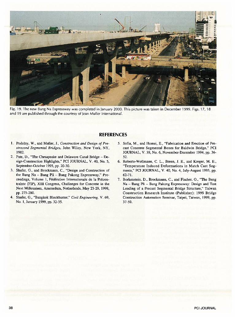
In areas where the main line iswidened, i.e., at the toll plazas and themerging areas of the ramps, it is necessary to place the superstructure onportal beams because the same cross-section of Highway 34 must be maintained. A total of 180 portals wereerected.
The portal beams are rigidly fixed atthe main line portal column and ateach end connected to the outsidecolumns by a hinge. The maximumspan is typically 27 m (89 ft) long.The beams are formed by match-castbox girders with vertical webs, whichare externally post-tensioned.
The portal columns have the sameform as the H-columns but have, inaddition, corbels with the same cross-section as the portal beams. A cast-in-place joint is necessary to provide forthe adjustment between these corbelsand the first match-cast segment. Therigid connection and the resulting tensile forces in this area are not onlypre-compressed by the external tendons in the beam but also by internaltendons in the upper part of the column (see Fig. 6).
The portal beams span three trafficlanes in each direction and it was notpermitted to interrupt the traffic forconstruction operations. The conventional method of using beams cast-in-place on lower formwork was in addition too slow considering the tighttime constraints. To fulfill both demands, it was decided to use precastcomponents that could be erected withan overhead truss.
This portal truss has two components, namely, a launching girder witha length of approximately two mainline spans and an erection girder, twoportal spans long. Both componentsare connected by a turntable, which isplaced on one column.
The complete truss is first launchedone span between the arms of the H-column, and then vertically and horizontally supported on three columns.Then, the turntable is fixed on the portal frame. Finally, the erection girderis turned by 90 degrees and is thensupported at the ends by the outsideportal columns.
The portal segments are delivered tothe center median where they are
picked up by a winch and taken totheir final location. Erection is, therefore, completely separated from trafficflow. Fig. 7 shows the erection procedure for portal segments.
D2/D3 Segments
D2 and D3 segments for two- orthree-lane decks are used for theramps, interchanges, and toll plazas.These types of segments have beenpreviously used successfully on otherexpressway projects by Bilfinger +
Berger in Bangkok. Both are box girders with a deck having a maximumvariable width of 15.60 m (51.2 ft)(see Fig. 8).
Note that these segments are erectedwith an overhead truss girder, which islaunched from column to column.First, the segments are hung from thetruss and properly aligned. They arethen post-tensioned longitudinally byexternal tendons in the box, and finally placed on the bearings.
D6 Segments
The D6 segments are the main partof the structure. They span in thetransverse direction with a width of27.20 m (89 ft) over six lanes of traffic. For typical segments, their heightand length are 2.60 and 2.55 m (8.53and 8.37 ft), respectively; for pier segments, their width is 1.775 m (5.82ft). The weights of typical girder andpier segments are 85 and 100 tonnes(94 and 110 tons), respectively. Theunusually slender cross-section hasinclined webs and two struts in themiddle of the segment (see Fig. 9).The inclination of the webs accentuates the curvature of the outside of thecolumns and carries this line to thehorizontal plane of the deck.
The spans are longitudinally prestressed by 22 tendons. Twenty ofthese tendons are placed externally inthe box and two are placed internallyin the edge beam. The transverse post-tensioning is accomplished not only
fl lflflf) - 1RflD2: 7,00-11,9Cm
0,20 m
D 3:
2,40 m
5,50 m
D2: 3,7Cm
metric dimensions
— I
Fig. 8. Configuration of D2/D3 segments.
27,20
precast strut
metric dimensions
Fig. 9. Configuration of D6 segments.
January-February 2000 31

deviator segment A
Fig. 10. Longitudinal post-tensioning.
by the tendons in the top slab, but alsoby placing them in the webs and bottom slab (see Figs. 10 and 11).
The H-column, the underslung truss,and the D6 segments of the superstructure were designed by Jean Muller International as an integrated approach tothe construction of the elevated mainline structure. The cross-beam of theH-column forms the support for thelaunching girder and the arms providethe horizontal support. The cross-section of the girder is V-shaped and it isequipped with a swivel crane for liftingand placing the segments.
The segments are placed on chassis(frame supports), which are equippedwith hydraulic jacks for adjusting andleveling the span.
The length of the girder is slightlylonger than the maximum of twospans. It comprises a load carryingplate girder in the front and a truss tosupport the launching in the rear. Theswivel crane can be placed either atthe nose of the plate girder or on thelast erected span. It is, therefore, possible to deliver the segment to a station below the swivel crane at grade aswell as to the already erected deck(see Fig. 12).
32
The upper flanges of the launchinggirder form the planes on which thechassis move. The swivel crane placeseach segment on one of these chassis,which is then pulled by a winch to the
Fig. 11. Transverse post-tensioning.
place of erection. The chassis areequipped with hydraulic jacks, whichallow for three-dimensional adjustments, i.e., vertical, horizontal, and rotational movements. After adjusting
tendons
deviator segment B
anchorages
Epier segment
bridge deck
/ ‘Nlive end dead end
dead end
____
cantilevers and box girder
1Ztendon
PCI JOURNAL

all the segments of a span, the externaltendons are placed in the box andstressed. Then, the girder is lowered totransfer the load to the bearings.
The girder is supported by three sliding chairs and two temporary chairsthat are required for launching. It islaunched by the front chassis that ismotorized. This chassis needed forlaunching is fixed to the erected superstructure and pushes the girder forwardusing a gear. For longer spans, the center of gravity during launching is infront of the last support. A reactionforce is transferred through the trussand into the erected deck.
Comparison of D2/D3with D6 Segments
The contract terms of the project allowed the bidders considerable freedom in bidding for the design. Bilfinger+ Berger elected to use D2/D3 segments for the ramps with a width varying from 6.0 to 10.75 m (20 to 35 ft).
For the 55 km (34 miles) mainline,they selected the D6 segments. Almost80 percent of the total deck area of1,900,000 m2 (20,400,000 sq ft) isformed by D6 segments. A comparison
Table 1. Comparison of material quantities in superstructure segments.
Quantities per square meter Segment Segmentof bridge deck 2xD3 D6
Concrete, m3 0.51 0.49
Reinforcing bars, kg 70.6 59.2
Post-tensioning tendons, kg 24.4 24.0
Conversion factors: 1 m2 = 10.76 sq ft; 1 m3 = 35.3 cu ft; 1 kg = 2.2 lbs.
Table 2. Quantities of components/materials in total structure.
Components/Materials Quantity
Deck area. m2 1,900,000D6 deck area, m2 1,400,000D2/D3 deck area, m2 500,000
D6 segments, pieces 21,320D2/D3 segments, pieces 18,250
Mainline piers, pieces 1,255
Piles, pieces 28,882
Concrete, m3 1,800,000
Reinforcing bars, tonnes 167,000
Post-tensioning tendons, tonnes 52,240
Conversion factors: I m2 = 10.76 sq ft; 1 m3 = 35.3 cu ft; I tonne = 1.10 tons.
Jill,
Fig. 12. Underslung erection girder.
January-February 2000 33
of the main material quantities of D3and D6 segments is shown in Table 1.
Evaluated by local prices in Bangkok,the quantity differences alone reflect asavings of 7 percent in the superstructure. Of course, these savings are notonly limited to the superstructure, butextend to the substructures as well.
Construction Speed andOverall Material Quantities
The biggest advantage of segmental construction with external post-tensioning and dry joints is the speedwith which the superstructure can beerected. In bridge construction, thecritical path (after a given startingperiod) always shifts to the superstructure. Any increase in the rate oferection directly accelerates the construction period.
For the BNE project, six overheadtrusses (D21D3) and five underslunggirders (D6) were used. When all thegirders are in operation, 2500 m (8200ft) of ramps and 2100 m (6890 ft) ofmainline deck were erected per month.In square meters of deck area, theerection speed for D6 girders wastwice as high as for the D2/D3 trusses.
At the same time, all the logistics, i.e.,production, handling, hauling, andother operations are simplified. Thetotal quantities of components/materials of the project are listed in Table 2.
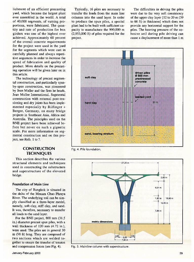
THE BANG BOPRECASTING YARD
In order to construct the BNE project, a giant precasting yard had to beset up to fabricate the thousands ofsegments required for the bridge. TheBang Bo precasting plant was constructed at Kilometer 29, about 4.5 km(2.8 miles) north of the expressway.Comprising an area of about 650,000m2 (7,000,000 sq ft), the plant was logistically planned down to the mmutest detail.
The marshy terrain in the delta of theMenam Chao Phraya River, togetherwith access roads, had to be completelydeveloped in order to efficiently produce and transport the heavy precastconcrete components. The entire production area was founded on driven reinforced concrete piles and overlaidwith a cast-in-place concrete slab.
The amount invested in constructingthe complete plant, without counting
the cost of land, equipment, and transportation facilities was about $26 million. The Bang Bo precasting yard(see Fig. 13) is the largest plant in theworld and boasts the highest installedproduction capacity of precast components ever achieved.
Construction of the plant began inthe summer of 1995. Within 9 monthsafter starting the yard fill, productionof the segments commenced. A totalof 40,000 bridge segments and 30,000other precast reinforced concrete elements such as road barriers and I-beams for the ramps were produced.The facility also contained workers’camps, canteens, offices and laboratories, carpentry, mechanical and welding workshops, a central store, a reinforcing bar cutting and bending shop,plus an area for the production and assembly of post-tensioning ducts.
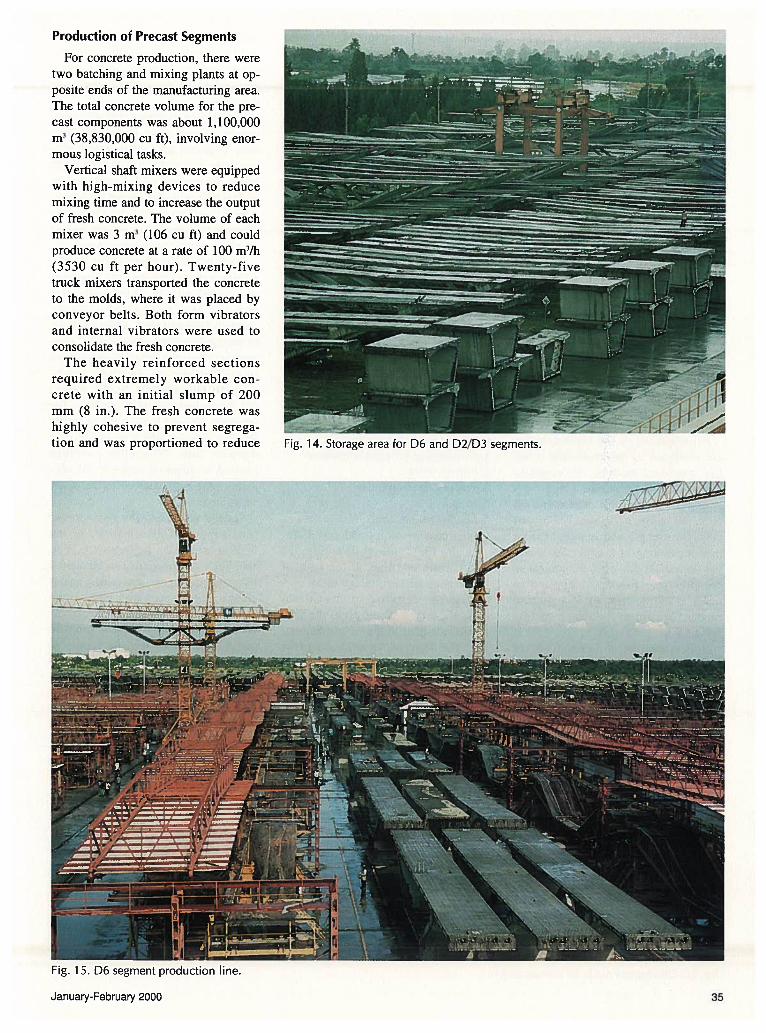
Approximately 1800 superstructure segments (D2/D3, D6, and portals) were produced per month in aquality controlled environment. Thestorage area for segments and otherprecast sections (see Fig. 14) wasabout 260,000 m2 (2,800,000 sq ft),corresponding to a production periodof 7 weeks.
Fig. 13. Layout of precasting yard.
34 PCI JOURNAL
Production of Precast Segments
For concrete produCtiOfl there weretwo batching and mixing plants at opposite ends of the anufacturiflg area.The total concrete volume for the precast components was about 1,100,000m3 (38,830,000 CU ft), involving enormous logistical tasks.
Vertical shaft mixers were equippedwith highmiXiflg devices to reducemixing time and to increase the outputof fresh concrete. The volume of eachmixer was 3 m3 (106 cu ft) and couldproduce concrete at a rate of 100 rn3fb(3530 cu ft per hour). Twenty-fivetruck mixers transported the concreteto the molds, where it was placed byconveyor belts. Both form vibratorSand internal vibratorS were used toconsolidate the fresh concrete.
The heavily reinforced sectionsrequired extremely workable concrete with an initial slump of 200mm (8 in.). The fresh concrete washighly cohesive to prevent segregation and was proportioned to reduce
Fig. 15. D6 segment production line.
JanuaryFebrUarY 2000

bleeding water to zero. The specified compressive strength for thesegments was 55 MPa (8000 psi).
In general, it is not practical to limitthe placing temperature of fresh concrete, since a temperature suitable toone specific job might not be appropriate for another situation. For durability reasons, it is more beneficial toknow the influence of temperature onfresh concrete and on the properties ofhardened concrete, and to take appropriate measures to cool the concrete.In producing high quality precast concrete, it has been found that a maximum placing temperature of 33 to35°C (91 to 95°F) is satisfactory.
The unformed surfaces of the concrete were covered with a plastic sheetto prevent evaporation of the mixingwater. The plastic sheet is placed insuch a way that a 3 cm (1 in.) thicklayer of air is confined. This reducesheat dissipation due to cement hydration and minimizes thermal cracking.
All segments of the superstructureare produced by match-casting usingthe short-bed method. To expeditematch-casting operations, a high-earlystrength concrete mix was required.After 10 hours, a 20 MPa (2900 psi)concrete strength was required beforepost-tensioning of a deck slab couldget started. At this time, 50 percent ofthe prestress force was applied inorder to allow stripping and shiftingof the segment to the match-castingposition.
Superstructure components wereproduced in stationary molds, wherethe previous segment serves as thebulkhead for the following segment tobe cast. In general, these molds are
fixed. However, to impart curvatureon a particular segment, variablemolds are also needed. In addition,there is also a difference between themolds for a typical superstructure segment and those for a pier segment.
For the production of D6 segments,38 molds were typical whereas only10 molds were needed for a pier segment. Molds for D21D3 segments havea typical segment to pier ratio of 19 to7, i.e., a total of 26 molds.
Typical segments were cast,stripped, moved to a match-castingposition, and surveyed within one day.For the pier segments, the formworkand reinforcing bar cages were morecomplicated and, therefore, the castingcycle took 2 days. To achieve thishigh rate of production, special precasting knowledge and technical skillare required.
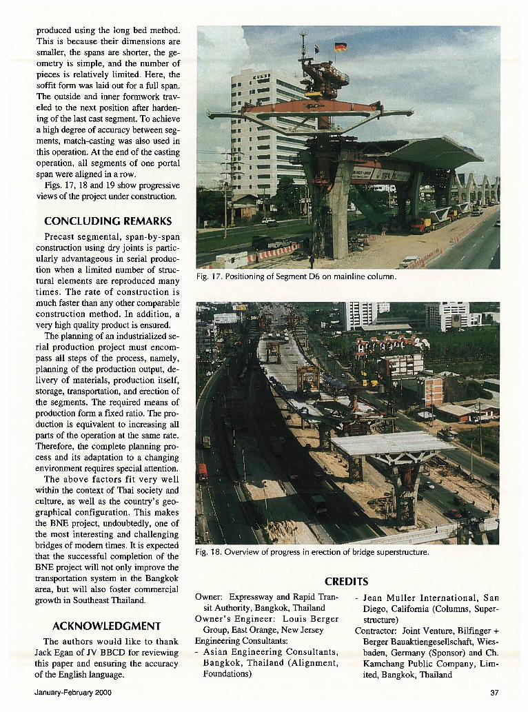
To illustrate this operation, two D6production lines are shown in Fig. 15.In the transverse direction, they are arranged in the following pattern:1. Reinforcing bar cage fabrication2. Survey towers3. Tower cranes on rails4. Molds5. Match-cast position6. Intermediate storage with travel lift
In the longitudinal direction, 12molds form one line, at the ends ofwhich there are two storage areas.
First, the struts and transverse tendons were transported from the prefabrication area to the reinforcing barjigs. The fixing of the reinforcing barstogether with the struts, transverse tendons, and forms for the deviators withdiabolos (through which the longitudinal tendons will later be pulled) re
quired a full day’s work. The moldsand the match-cast segment were surveyed and the reinforcing bar cageswere lifted by the tower cranes intothe molds.
Span layout drawings define the geometry of each span. Before the concrete is placed for casting a new segment, the x, y, and z coordinates of thejoints were checked for accuracy inaccordance with the layout drawings.Special software was developed tomonitor the geometric survey and tocheck the after-cast inspection survey.
Each mold has three soffit forms.After post-tensioning, the segmentwas shifted on rails to the match-castposition. After casting, the followingsegment is transported, again on rails,to the intermediate storage area, situated between two adjacent productionlines. If necessary, finishing patchwork on the segments can be carriedout. From here, travel lifts picked thesegments up and brought them to thestorage areas at both ends of the production line. When the concretereached its required strength, the segments were fully stressed in the transverse direction.
Special attention was given to thetime-dependent deformations of thewide spanning D6 segments (see Fig.16). Such deformations can be causedby transverse post-tensioning especially since the cantilever arms of thepier and typical segments have different stiffnesses. Care must be taken toavoid different deflections (concretemix, curing, layout, sequence, andtiming of the post-tensioning).
Unlike the segments of the superstructure, the portal segments were
Fig. 16. D6 segment ready for transportation./
36 PC! JOURNAL
produced using the long bed method.This is because their dimensions aresmaller, the spans are shorter, the geometry is simple, and the number ofpieces is relatively limited. Here, thesoffit form was laid out for a full span.The outside and inner formwork traveled to the next position after hardening of the last cast segment. To achievea high degree of accuracy between segments, match-casting was also used inthis operation. At the end of the castingoperation, all segments of one portalspan were aligned in a row.
Figs. 17, 18 and 19 show progressiveviews of the project under construction.
CONCLUDING REMARKSPrecast segmental, span-by-span
construction using dry joints is particularly advantageous in serial production when a limited number of structural elements are reproduced manytimes. The rate of construction ismuch faster than any other comparableconstruction method. In addition, avery high quality product is ensured.
The planning of an industrialized serial production project must encompass all steps of the process, namely,planning of the production output, delivery of materials, production itself,storage, transportation, and erection ofthe segments. The required means ofproduction form a fixed ratio. The production is equivalent to increasing allparts of the operation at the same rate.Therefore, the complete planning process and its adaptation to a changingenvironment requires special attention.
The above factors fit very wellwithin the context of Thai society andculture, as well as the country’s geographical configuration. This makesthe BNE project, undoubtedly, one ofthe most interesting and challengingbridges of modem times. It is expectedthat the successful completion of theBNE project will not only improve thetransportation system in the Bangkokarea, but will also foster commercialgrowth in Southeast Thailand.
ACKNOWLEDGMENTThe authors would like to thank
Jack Egan of JV BBCD for reviewingthis paper and ensuring the accuracyof the English language.
CREDITSOwner: Expressway and Rapid Tran
sit Authority, Bangkok, ThailandOwner’s Engineer: Louis Berger
Group, East Orange, New JerseyEngineering Consultants:- Asian Engineering Consultants,
Bangkok, Thailand (Alignment,Foundations)
- Jean Muller International, SanDiego, California (Columns, Superstructure)
Contractor: Joint Venture, Bilfinger +
Berger Bauaktiengesellschaft, Wiesbaden, Germany (Sponsor) and Ch.Kamchang Public Company, Limited, Bangkok, Thailand
—Ii-I I
I — !I-.
—-
- — !— I
:‘.r1
Fig. 17. Positioning of Segment D6 on mainline column.
Fig. 18. Overview of progress in erection of bridge superstructure.
January-February 2000 37
REFERENCES
1. Podolny, W., and Muller, 3., Construction and Design of Prestressed Segmental Bridges, John Wiley, New York, NY,1982.
2. Pate, D., “The Chesapeake and Delaware Canal Bridge — Design-Construction Highlights,” PCI JOURNAL, V. 40, No. 5,September-October 1995, pp. 20-30.
3. Shafer, G., and Brockmann, C., “Design and Construction ofthe Bang Na — Bang Ph — Bang Pakong Expressway,” Proceedings, Volume 1, Fédération Internationale de la Précontrainte (FTP), XIII Congress, Challenges for Concrete in theNext Millennium, Amsterdam, Netherlands, May 23-29, 1998,
pp. 275-280.4. Shafer, G., “Bangkok Blockbuster,” Civil Engineering, V. 69,
No. 1, January 1999, pp. 32-35.
5. Sofia, M., and Homsi, E., “Fabrication and Erection of Precast Concrete Segmental Boxes for Baldwin Bridge,” PCIJOURNAL, V. 39, No. 6, November-December 1994, pp. 36-52.
6. Roberts-Wollmann, C. L., Breen, J. E., and Kreger, M. E.,“Temperature Induced Deformations in Match Cast Segments,” PCI JOURNAL, V. 40, No. 4, July-August 1995, pp.62-71.
7. Borkenstein, D., Brockmann, C., and Fischer, 0., “The BangNa — Bang Ph — Bang Pakong Expressway: Design and TestLoading of a Precast Segmental Bridge Structure,” TaiwanConstruction Research Institute (Publisher): 1999 BridgeConstruction Automation Seminar, Taipei, Taiwan, 1999, pp.37-59.
I—
.4 %_,_•_
Fig. 19. The new Bang Na Expressway was completed in January 2000. This picture was taken in December 1999. Figs. 1 7, 18and 19 are published through the courtesy of Jean Muller International.
38 PCI JOURNAL