Embed Size (px)
Citation preview

In the automotive industry, galvanized steel sheets have been applied for quality improvement. However, the porosity defects generated during welding and increased spattering cause a debasement of welding workability. Porosity-generating behavior, which had not hitherto been clarified, was observed in this study, which also examines a method of reducing both the porosity defects and spatter. The results indicate that releasing zinc vapor from directly under the arc to outside the molten pool is effective in reducing porosity defects. Based on this knowledge, the problem was solved by optimizing (a) the composition and size of the welding material, (b) the shielding gas composition and (c) the current pulse wave pattern. This new welding process was named the "J-Solution Zn".
Introduction
Recently, the automotive industry is increasingly using galvanized steel sheets to improve long-term quality and to adapt thinner sheets for weight reduction. Galvanized steel sheets, however, are very poor in weldability compared with ordinary steel sheets. One of their major drawbacks is that the zinc is vaporized during welding, causing porosity defects such as pits that are open onto the weld-bead surface and blowholes that remain inside the beads. Another drawback is that the zinc gas blows off welding droplets and molten pools, which increases the amount of spatter (Fig. 1). Conventionally, efforts to solve these problems have focused on either the improvement of welding consumables or welding power sources. 1) - 4) These solutions, however, have not yet been able to resolve the issues of porosity resistance and spatter simultaneously. The porosity defects are considered
to be formed by the zinc gas, generated from the deposit on the lapped portion, penetrating into the molten pool; however, the details of their generation behavior have not been clarified yet, either. In the present study, we conducted a dynamic observation of porosity formation behavior in the lap fillet welds of galvanized steel sheets and, on the basis of the observation results, have proposed guidelines to reduce porosity defects. 5) This report also describes the features and effects of a newly developed welding process, "J-Solution TM note 1) Zn" 6) - 9) (hereinafter referred to as "J-Solution Zn"), for galvanized steel sheets. This new process was developed in the course of the present study to reduce porosity defects and the amount of spatter simultaneously.
1. The generation mechanism of porosity defects
1.1 Experimental method
The test material was galvannealed steel sheets 2.3mm thick (with 45g/m2 of zinc coating). Spot welding was used to ensure the adhesion of the lapped surfaces (Fig. 2), so as to prevent zinc vapor from escaping to the outside through gaps. Pulsed MAG welding was performed under the conditions shown in Table 1 to study the effect of the welding positions on the numbers of pits and blowholes generated. The surface of each molten pool during welding was observed by a high-speed video camera at a frame rate of 6,000fps. The porosity formation phenomenon inside each molten pool was observed dynamically using a high-intensity X-ray radiography imaging system (an installation of the Joining and Welding Research Institute, Osaka University), shown in Fig. 3, at a frame rate of 500fps.
New Welding Process, "J-SolutionTM Zn", Suitable for Galvanized Steel in the Automotive IndustryShun IZUTANI *1, Dr. Kei YAMAZAKI *1, Reiichi SUZUKI *1
*1 Welding Process Dept., Technical Center, Welding Business
note 1) "J-Solution" is a trademark jointly owned by Kobe Steel, Ltd. and DAIHEN Corporation.Fig. 1 Welding problems of galvanized steel
Fig. 2 Schematic diagram of lap joint in fillet welding
KOBELCO TECHNOLOGY REVIEW NO. 32 DEC. 2013 16

1.2 Observation of porosity defects
The generation of porosity defects has been known empirically to be greatly affected by welding positions. Fig. 4 shows the number of pits generated during welding in the horizontal and downward positions, while Fig. 5 shows the number of blowholes generated during the same. As is shown clearly, the downward position causes increased numbers of pits and blowholes to be generated, in comparison with the horizontal position. Fig. 6 shows the surface conditions of the molten pool captured by a high-speed video camera. It has been confirmed that larger numbers of pits and blowholes tend to be generated when the zinc gas, vaporized from the zinc layer, is discharged from inside the molten pool in the rear of the arc, as in the case of the downward position shown in Fig. 6 (b). On the other hand, it has also been confirmed that pits are unlikely to be generated, and the number of blowholes is decreased, when the zinc gas is discharged from directly under the arc, as in the case of the horizontal position shown in Fig. 6 (a). This tendency was the same for various welding currents and arc voltages. The downward position is characterized by the fact that the molten pool moves ahead of the arc. Thus, the present experimental results imply that the porosity formation phenomenon is greatly affected by the conditions of the dug portion directly under the arc. On the basis of the above assumption, the phenomenon of porosity formation directly under the arc was confirmed. A high-intensity
X-ray radiography imaging system was used to dynamically observe the formation behavior of porosity defects inside the molten pool. The results are shown in Fig. 7 and Fig. 8. This system offers clear transmission images, allowing distinct observation of the formation and growth of porosity defects even at the frame rate of 500fps. One characteristic of the phenomenon is that all the porosity defects originate and grow from the root portion of the sheet lap, with all of the points of origin being formed under the thin layer of the molten metal directly under the arc. In other words, there is no sudden appearance of porosity originating to the rear of, and slightly away from, the arc. Another characteristic is that a significant amount of zinc gas is constantly released outside the molten pool from the dug portion directly under, and immediately to the rear of, the arc. For example, a porosity defect formed at the position indicated by an arrow in Fig. 7 (a) disappeared at 4ms as a result of the release of gas outside the molten
Table 1 Welding conditions
Fig. 3 Schematic diagram of X-ray radiography imaging system
Fig. 5 Effect of welding position on blowhole generation
Fig. 6 Observation of molten pool surface by high-speed video camera imaging
Fig. 4 Effect of welding position on number of pits
KOBELCO TECHNOLOGY REVIEW NO. 32 DEC. 201317

pool (Fig. 7 (b)). Furthermore, a porosity defect formed again at 8ms (Fig. 7 (c)) and disappeared at 12ms (Fig. 7 (d)). These phenomena have also been observed from the surface of the molten pool, as shown in Figs. 7 (e) and (f). Thus a porosity defect repeatedly appears and disappears directly under the arc; however, once its point of origin is carried to the rear of the arc, there is no case in which a porosity defect completely disappears there. For example, a porosity defect that had grown large, as indicated by an arrow in Fig. 8 (a), once shrank at 4ms as a result of the release of gas, with its point of origin not disappearing (Fig. 8 (b)) and started to grow again at 8ms (Fig. 8 (c)). In other words, it is considered that, once a point of origin is carried to the rear of the arc, it remains as a blowhole or a pit in most cases. The relationship between the dug depth and the number of blowholes is shown in Fig. 9. The dug depth directly under the arc was obtained from the X-ray video image. It turns out that as the depth increases, the number of blowholes decreases.
As described above, the final number of porosity defects generated for a zero joint gap is considered to be governed by the relative positions of the arc and molten pool. Therefore, it is considered that a significant suppression of porosity formation can be effectively achieved by maintaining the molten metal layer directly under the arc as thin as possible, such that the zinc gas can be released outside the molten pool at an early stage.
2. Study on the reduction of porosity defects
The observation described in section 1 has revealed an important subject for porosity reduction: that is, how to release zinc gas from directly under the arc. To release zinc gas, it is considered effective to somehow decrease the amount of the molten metal that directly flows in under the arc, such that the surface of the base material is exposed. The shape of the molten pool directly under the arc is governed by the balance between the arc force and the fluidity of the molten metal (Fig.10). It is considered that the digging directly under the arc can be promoted by (a) controlling the balance of forces exerted on the molten pool by suppressing the fluidity and (b) increasing the arc force. To achieve these objectives, we studied the basic elements of MAG welding, i.e., welding wire, shielding gas and the waveform control of electric current by the welding power source.
Fig. 7 Behavior of blowhole released from under the arc to outside of the molten pool
Fig. 8 Behavior of residual blowholes that was not released under the arc
Fig. 9 Relationship between depth of molten pool under the arc and porosity defects
Fig.10 New ideas for reduction of porosity defects
KOBELCO TECHNOLOGY REVIEW NO. 32 DEC. 2013 18

2.1 Study on welding wire
One method of suppressing the fluidity, against gravity, of molten metal flowing in directly under the arc is to increase its surface tension. The surface tension of molten iron is known to depend on the chemical composition of the wire. In particular, the oxygen (O) content and sulfur (S) content, the elements called "chalcogen elements", are known to be two major determining factors. 10) Of the two, we focused on the S content, which is easier to control. On the other hand, increasing the arc force requires a large current output. This can be achieved by decreasing the electrical resistance of the wire so as to reduce the contribution of the Joule heat at the wire extension. Since the electrical resistance of the wire depends on the chemical composition, we focused on manganese (Mn), which contributes the most, and we controlled the amount of it.
2.1.1 Experimental method
Table 2 shows the chemical compositions of the tested wires having varying S and Mn content. In general, the surface tension increases with decreasing S content. Therefore, wire 3 exhibits the greatest surface tension among the wires tested. On the other hand, wire 4 has the lowest electrical resistance, since the resistivity decreases with decreasing Mn content. These wires were used to study the method for exposing the base material directly under the arc. In each case, welding was conducted in a downward position with a lead angle of 30 degrees, the position which is known to be prone to porosity defects. The welding was repeated three times for a given condition. The number of pits was counted visually, while that of blowholes was determined by radiographic testing (RT).
2.1.2 Reduction of porosity by welding wire composition
Fig.11 compares the numbers of blowholes obtained for the tested wires. (Each number represents the average of three repeats.) The number of blowholes decreases with decreasing
S content (i.e., increasing surface tension). In particular, blowholes larger than 1.5mm have decreased significantly. This result confirms that reducing the additive amount of S, a surface active element, to a minimum and thus increasing the surface tension is an effective approach for reducing blowholes. It should be noted that wire 4, having low Mn content, exhibits a significantly decreased number of blowholes compared with wire 3, which has the same S content. This is considered to have been caused by the decreased electrical resistance of the wire, which increased the electric current required for maintaining the melting rate of the wire and increased the arc force. Two types of lap fillet welding were performed, both in a downward position with a lead angle of 30 degrees, using wire 1 (low surface tension) and wire 4 (high surface tension, low electrical resistance) respectively. For each welding, the shape of the molten pool was captured by a high-speed video camera (Fig. 12). Wire 1, with its low surface tension, was more affected by gravity and exhibited a wide leading distance of molten pool. On the other hand, wire 4, having a higher surface tension, exhibited a smaller leading distance with an increased dug depth. This is considered to have been caused by the molten metal's being pushed up to the rear by the arc force and maintaining its shape against gravity without flowing into a position directly under the arc. These results imply that the wire composition that effectively resists porosity formation will be found in the low S - low Mn system.
Table 2 Chemical composition of test wires
Fig.12 Comparison of leading distance of molten pool against arc in conventional, as opposed to developed wire
Fig.11 Comparison of number of blowholes
KOBELCO TECHNOLOGY REVIEW NO. 32 DEC. 201319

2.2 Study on shielding gas
Shielding gas is known to greatly affect the shape of the arc. In the case of a mixture of Ar and CO2, a higher CO2 gas ratio brings a cooling effect as a result of the decomposition reaction of CO2, which causes the constriction of the arc. 11) This effect causes the arc force to be more concentrated in a small area. In other words, the current density of the arc is increased, increasing the digging action directly under the arc.
2.2.1 Experimental method
To verify the above assumption involving the effect of the CO2 gas ratio, pulsed MAG welding was performed using welding wire YGW15 (φ1.2mm). Two types of gas mixtures, 80%Ar - 20%CO2 and 70%Ar - 30%CO2, were used to study porosity in the weld. The porosity was evaluated in the same manner as described in section 2.1.
2.2.2 Reduction of porosity defects by gas composition
Fig.13 shows the effect of shielding gas composition on porosity defects. The commonly used gas mixture, 80%Ar - 20%CO2, has caused more than 40 blowholes. On the other hand, the mixture with increased CO2 gas ratio, 70%Ar - 30%CO2, has resulted in about 14 blowholes. The shape of the molten pool for each gas mixture, captured by a high-speed video camera, is shown in Fig.14. It has been demonstrated that the gas composition, 70%Ar - 30%CO2, results in an increased digging width in the molten pool. Thus, the increased CO2 gas ratio is confirmed to increase the arc force, enabling the maintenance of a digging shape appropriate for porosity resistance. However, a CO2 gas ratio exceeding 30% results in an extreme
increase in spatter, which significantly deteriorates welding workability. Thus a CO2 gas ratio of 30% is considered to be the upper limit in practice.
2.3 Study on welding current waveform
The relationship between the welding method and the number of porosity defects was studied using a low-frequency superimposed pulse waveform 12) with modulated frequency and peak current, as shown in Fig.15, as a way of creating contrast in the arc force.
2.3.1 Experimental method
Welding was performed using the wire YGW15 (φ1.2mm) and the 70%Ar - 30%CO2 shielding gas that had been confirmed to be effective in reducing porosity defects. The frequency of the low-frequency superimposed pulse was kept in the range from 0 to 30Hz.
2.3.2 Reduction of porosity defects by controlling current waveform
Fig.16 shows the relationship between the number of blowholes and frequency. In the case of the low-frequency superimposed pulse welding, the molten pool was observed to vibrate strongly at the frequencies of 10Hz and 20Hz. This vibration facilitates the exposure of the base material directly under the arc and promotes the release of the zinc gas. This is considered to have caused the reduced number of porosity defects at 10Hz and 20Hz compared with the conventional pulse.
Fig.13 Effect of shielding gas composition on porosity defect
Fig.14 Relationship between shielding gas composition and width of arc-dug portion in molten pool
Fig.15 Swing behavior of molten pool caused by low-frequency superimposed pulse
KOBELCO TECHNOLOGY REVIEW NO. 32 DEC. 2013 20

3. Method for reducing spatter
As shown in Fig. 1, the welding of galvanized steel sheet is inherently susceptible to spatter. In addition, the use of a gas with a higher than conventional CO2 ratio, the gas known to exhibit excellent porosity resistance, has a multiplier effect of making the welding more susceptible to spatter compared with the conventional welding method. This is because the generation of zinc gas and increased CO2 ratio cause the droplet to remain at the tip of the wire without detaching from it, making the droplet grow large and hindering its detachment. Hence, the reduction of spatter was studied using a method for smoothly detaching the droplet by employing a two-step pulse waveform (Fig.17) in which the first peak current is kept at a high level and the second peak current at a lower level. A wire with a small diameter was also used to facilitate droplet detachment.
3.1 Experimental method
A gas mixture of 70%Ar - 30%CO2 was used. Droplet transfer when using the conventional rectangular pulse waveform was compared with that of the two-step pulse waveform.
Another comparison was made between the wire diameters of φ1.2mm and φ1.0mm.
3.2 Spatter reduction effect of two-step pulse waveform and small diameter wire
Fig.18 shows the shapes of the arcs produced by the conventional rectangular pulse and two-step pulse, both using the 70%Ar - 30%CO2 gas mixture. In the case of the conventional rectangular pulse, in which the pulse peak current is constant, the arc is generated in a low position, which disables the pinch force that should be exerted throughout the molten portion of the wire, making the droplet transfer unstable. The resultant phenomena includes the scattering of the droplet outside the molten pool by the zinc vapor blown from below, and the short-circuiting of the droplet, which has been unable to detach and has grown excessively, with the base material, both resulting in spatter. In the case of the two-step pulse waveform, on the other hand, only a small amount of spatter was confirmed. This is a result of the arc generated at a high position and the stable growth and detachment of the droplet. In addition, a smaller wire diameter tends to yield a smaller droplet, which increases the current density, improving the ability of the electromagnetic pinch force to detach the droplet. This enables droplet detachment at an early stage. Especially in the case of pulse welding, in which a strong electromagnetic pinch force is exerted at the peak current, droplet transfer can occur smoothly even when the mixed gas atmosphere used is 70%Ar - 30%CO2, with a CO2 ratio higher than that of the conventional atmosphere. Fig.19 shows the effect of shielding gas and wire diameter on spatter generation. The amount of spatter for φ1.2mm wire was about 1.1g/min when combined with the commonly used shielding gas (80%Ar - 20%CO2) and conventional rectangular pulse. In contrast, the use of the 70%Ar - 30%CO2 gas increased the amount of spatter to 1.4g/min. On the
Fig.17 Two-step pulse wave form and parameterFig.18 Comparison in arc shape between conventional
pulse and two-step pulse
Fig.16 Relationship between superimposed frequency and number of blowholes
KOBELCO TECHNOLOGY REVIEW NO. 32 DEC. 201321
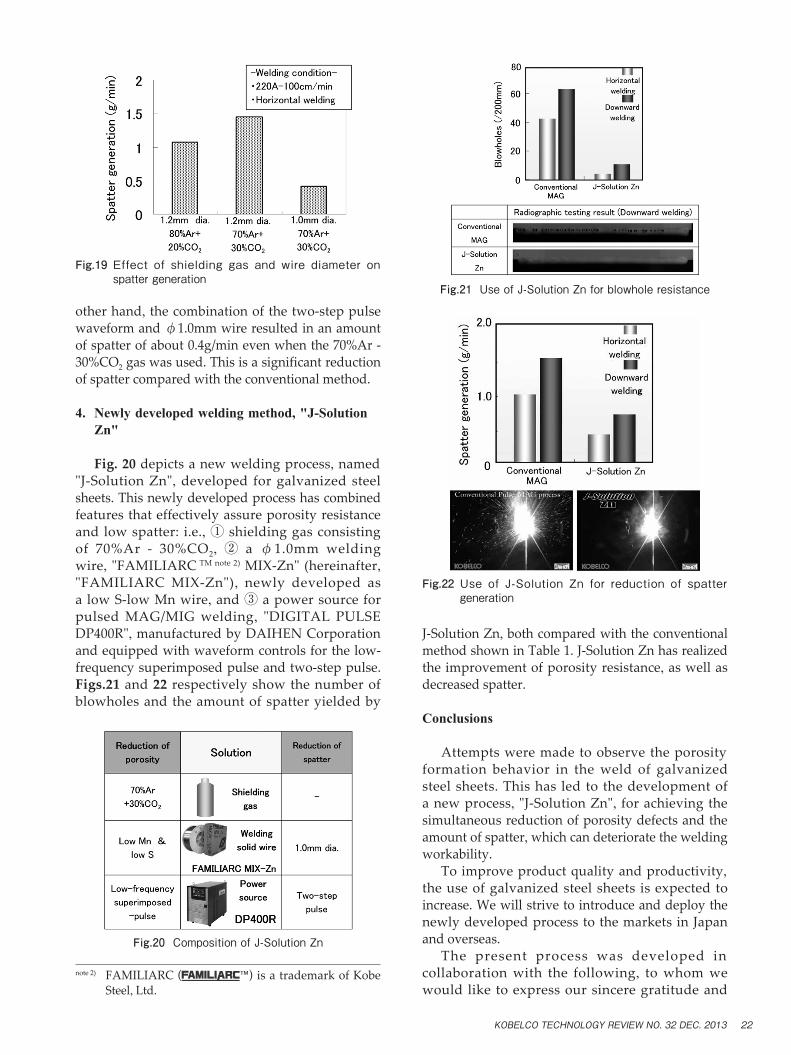
other hand, the combination of the two-step pulse waveform and φ1.0mm wire resulted in an amount of spatter of about 0.4g/min even when the 70%Ar - 30%CO2 gas was used. This is a significant reduction of spatter compared with the conventional method.
4. Newly developed welding method, "J-Solution Zn"
Fig. 20 depicts a new welding process, named "J-Solution Zn", developed for galvanized steel sheets. This newly developed process has combined features that effectively assure porosity resistance and low spatter: i.e., ① shielding gas consisting of 70%Ar - 30%CO2, ② a φ1.0mm welding wire, "FAMILIARC TM note 2) MIX-Zn" (hereinafter, "FAMILIARC MIX-Zn"), newly developed as a low S-low Mn wire, and ③ a power source for pulsed MAG/MIG welding, "DIGITAL PULSE DP400R", manufactured by DAIHEN Corporation and equipped with waveform controls for the low-frequency superimposed pulse and two-step pulse. Figs.21 and 22 respectively show the number of blowholes and the amount of spatter yielded by
J-Solution Zn, both compared with the conventional method shown in Table 1. J-Solution Zn has realized the improvement of porosity resistance, as well as decreased spatter.
Conclusions
Attempts were made to observe the porosity formation behavior in the weld of galvanized steel sheets. This has led to the development of a new process, "J-Solution Zn", for achieving the simultaneous reduction of porosity defects and the amount of spatter, which can deteriorate the welding workability. To improve product quality and productivity, the use of galvanized steel sheets is expected to increase. We will strive to introduce and deploy the newly developed process to the markets in Japan and overseas. The present process was developed in collaboration with the following, to whom we would like to express our sincere gratitude and
Fig.19 Effect of shielding gas and wire diameter on spatter generation
Fig.20 Composition of J-Solution Zn
Fig.21 Use of J-Solution Zn for blowhole resistance
Fig.22 Use of J-Solution Zn for reduction of spatter generation
note 2) FAMILIARC ( ) is a trademark of Kobe Steel, Ltd.
KOBELCO TECHNOLOGY REVIEW NO. 32 DEC. 2013 22

appreciation: Messrs. T. Kamizono, Y. Ueda and K. Nakamura of DAIHEN Corporation for their efforts in developing the current waveform control, Professor M. Tanaka of Joining and Welding Research Institute, Osaka University, who allowed us the use of their high-intensity X-ray radiography imaging system, and Assistant Professor S. Tashiro for his cooperation in capturing the images.
References
1) R. Suzuki. Welding Technology 9-12. 2006. Sanpo Publications Inc.
2) I. Kimoto et al. Preprints of the National Meeting of JWS, 58. 1996, p.52.
3) H. Hirai. DENKI-SEIKO (ELECTRIC FURNACE STEEL). 1996, 67 (3), p.221.
4) H. Matsui et al. Quarterly Journal of the Japan Welding Society. 1998, 16 (1), p.45.
5) K. Yamazaki et al. Preprints of the National Meeting of JWS, 90. 2012, p.90.
6) S. Izutani et al. Preprints of the National Meeting of JWS, 90. 2012, p.92.
7) K. Nakamura et al. Preprints of the National Meeting of JWS, 90. 2012, p.94.
8) Y. Ueda et al. Preprints of the National Meeting of JWS, 90. 2012, p.96.
9) S. Izutani et al. Preprints of the National Meeting of JWS, 91. 2012, p.396.
10) K. Nakamura et al. TETSU-TO-HAGANE. The Iron and Steel Institute of Japan. 1983, 69 (16), p.1989.
11) M. Tanaka et al. J. Plasma Fusion Res. 2012, Vol.88, No.5, p.276.
12) Y. Ueda et al. Preprints of the National Meeting of JWS, 85. 2009, p.88.
KOBELCO TECHNOLOGY REVIEW NO. 32 DEC. 201323


![NG ZN PZI IO OLV J] OKXI IK/ ISXKNN QJK8VOI IN](https://img.dokumen.tips/doc/110x75/61588cba04fb8d45a01cda71/ng-zn-pzi-io-olv-j-okxi-ik-isxknn-qjk8voi-in.jpg)