Embed Size (px)
Citation preview

New Method for Directional Modulation using Beamforming:
Applications to Simultaneous Wireless Information and Power
Transfer and Increased Secrecy Capacity
Randy Matthew Yamada
Dissertation submitted to the faculty of the
Virginia Polytechnic Institute and State University
in partial fulfillment of the requirements for the degree of
Doctor of Philosophy
In
Electrical Engineering
Lamine Mili, Chair
R. Michael Buehrer
T. Charles Clancy
Serkan Gugercin
Allan O. Steinhardt
September 14, 2017
Arlington, Virginia
Keywords: Directional Modulation, Physical Layer Security, Beamforming, Array, Broadcast
Channel, Secrecy
Copyright 2017, Randy M. Yamada

New Method for Directional Modulation using Beamforming:
Applications to Simultaneous Wireless Information and Power Transfer and Increased Secrecy
Capacity
Randy Matthew Yamada
ABSTRACT
The proliferation of connected embedded devices has driven wireless communications into
commercial, military, industrial, and personal systems. It is unreasonable to expect privacy and
security to be inherent in these networks given the spatial density of these devices, limited spectral
resources, and the broadcast nature of wireless communications systems. Communications for
these systems must have sufficient information capacity and secrecy capacity while typically
maintaining small size, light weight, and minimized power consumption. With increasing
crowding of the electromagnetic spectrum, interference must be leveraged as an available resource.
This work develops a new beamforming method for direction-dependent modulation that provides
wireless communications devices with enhanced physical layer security and the ability to
simultaneously communicate and harvest energy by exploiting co-channel interference. We
propose a method that optimizes a set of time-varying array steering vectors to enable direction-
dependent modulation, thus exploiting a new degree of freedom in the space-time-frequency
paradigm. We formulate steering vector selection as a convex optimization problem for rapid
computation given arbitrarily positioned array antenna elements.
We show that this method allows us to spectrally separate co-channel interference from an
information-bearing signal in the analog domain, enabling the energy from the interference to be
diverted for harvesting during the digitization and decoding of the information-bearing signal. We
also show that this method provides wireless communications devices with not only enhanced
information capacity, but also enhanced secrecy capacity in a broadcast channel. By using the
proposed method, we can increase the overall channel capacity in a broadcast system beyond the
current state-of-the-art for wireless broadcast channels, which is based on static coding techniques.
Further, we also increase the overall secrecy capacity of the system by enabling secrecy for each
user in the system. In practical terms, this results in higher-rate, confidential messages delivered
to multiple devices in a broadcast channel for a given power constraint. Finally, we corroborate
these claims with simulation and experimental results for the proposed method.

New Method for Directional Modulation using Beamforming:
Applications to Simultaneous Wireless Information and Power Transfer and Increased Secrecy
Capacity
Randy Matthew Yamada
GENERAL AUDIENCE ABSTRACT
The proliferation of connected devices has driven wireless communications into commercial,
military, industrial, and personal systems. It is unreasonable to expect privacy and security to be
inherent in these networks given the spatial density of these devices, limited available resources,
and the broadcast nature of wireless communications systems. Communications for these systems
need not only sufficient information capacity, but also the assurance that the available information
capacity remains confidential while typically maintaining small size, light weight, and minimized
power consumption. With increasing crowding of the electromagnetic spectrum due to the
numerous connected devices, interference between them must be leveraged as an available
resource.
This work develops a new method for electrically steering an array of antennas to overlay or
encode information onto a signal in a way that is direction-dependent and provides wireless
communications devices with enhanced security and the ability to simultaneously communicate
and harvest energy from interfering devices. We propose a method that optimizes a set of time-
varying array steering vectors to enable direction-dependent modulation, thus exploiting a new
degree of freedom in the traditional space-time-frequency paradigm. We formulate the selection
of steering vectors as a convex optimization problem for rapid computation given arbitrarily
positioned array antenna elements in three dimensions.
We show that this method allows us to separate interference from an information-bearing signal
in the analog domain, enabling the energy from the interference to be diverted for harvesting during
the digitization and decoding of the information-bearing signal. We also show that this method
provides broadcast wireless communications devices with not only increased information capacity,
but also assured secrecy. By using the proposed time-varying method, we can increase the overall
channel capacity in a broadcast system beyond the current state-of-the-art, which is based on static
encoding techniques. Further, we also increase the overall secrecy capacity of the system by
ensuring that each user in the system receives separate and confidential signals. In practical terms,
this results in higher-rate, confidential messages delivered to multiple devices in a broadcast
channel for a given power constraint. Finally, we corroborate these claims with simulation and
experimental results for the proposed method.

iv
To my family

v
I would first like to thank my advisor, Dr. Lamine Mili, for his enduring support in my
education and growth over the years, leading to the completion of this research. I would also like
to thank Dr. T. Charles Clancy, Dr. R. Michael Buehrer, and Dr. Serkan Gugercin for participating
in my committee. I would like to extend great appreciation to Dr. Allan Steinhardt for nearly a
decade of mentorship and to Dr. Joshua Conway for encouragement and support in developing this
research. I owe my academic and professional growth to each of you and more.
I must also thank my friends and family for providing me with a strong foundation. I would
like to especially thank mom, dad, Roger, and Kevin for the literal lifetime of optimism. I would
also like to recognize Phoebe and Petra, for being the reasons that I push myself. Finally, I owe
the entirety of this work to my wonderful wife, Esther, whose dedication to our family is the only
reason I could complete this work.
Acknowledgements

vi
1 Introduction ............................................................................................. 1
1.1 Research Objectives .................................................................................... 4
1.2 Literature Review of Directional Modulation ............................................. 4
1.3 Contributions............................................................................................. 10
1.4 Dissertation Organization ......................................................................... 13
2 A Proposed Method for Directional Modulation Using Beamforming16
2.1 Array Processing Construct and Signal Model ......................................... 17
2.2 Applying Directional Modulation ............................................................. 19
2.3 Efficiency of Directional Modulation ....................................................... 21
2.4 Array Steering Vector Formulation .......................................................... 23
Contents

vii
3 Simultaneous Wireless Information and Power Transfer Using Directional
Modulation .............................................................................................. 37
3.1 Overview ................................................................................................... 38
3.2 Prior Art .................................................................................................... 40
3.3 Harvesting Energy from Co-channel Interferers Using Beamforming ..... 41
4 Increased Secrecy Capacity Using Directional Modulation ............. 47
4.1 Disguising Transmissions for Physical Layer Secrecy ............................. 50
4.2 Increasing the Capacity of Confidential Messages over Wireless Broadcast
Channels 58
4.3 Secrecy Capacity in a Broadcast Channel ................................................ 63
5 Simulation Results ................................................................................ 65
5.1 Implementation Cost of the Proposed Beamforming Method .................. 66
5.2 Simultaneous Wireless Information and Power Transfer ......................... 69
5.3 Disguising Transmissions for Physical Layer Secrecy ............................. 74
5.4 Increasing the Capacity of Confidential Messages over Wireless Broadcast
Channels 78

viii
5.5 Robustness of the Proposed Method to Angle and Frequency ................. 85
6 Experimentation .................................................................................... 90
6.1 Objective ................................................................................................... 91
6.2 Experimental Setup ................................................................................... 91
6.3 Calibration................................................................................................. 93
6.4 Experimental Procedure .......................................................................... 102
6.5 Results ..................................................................................................... 105
7 Conclusions and Scope of Future Work ........................................... 111
7.1 Conclusions ............................................................................................. 111
7.2 Topics for Future Research ..................................................................... 112
8 Bibliography ......................................................................................... 117

ix
Figure 2.1: A state diagram of the array control system for directional modulation is shown. Here,
we specify two different states for the array – one where the steering vector 𝒘𝟎 is applied, and one
where the steering vector 𝒘𝟏 is applied. The desired modulation overlay induced in the directions
of interest, 𝒂𝒎 and 𝒂𝒏 are indicated for each transition for the two User case with BPSK overlay
modulation. The transitions shown in this state diagram represent half of the required control for
directional modulation; the other half of the required control is inherited by inverting the input
signal to the array. ......................................................................................................................... 24
Figure 2.2: A state diagram of the array control system for directional modulation for the three
User case and BPSK overlay modulation is shown. Here, we specify four necessary states and
steering vectors for the array to overlay modulation in the directions of interest, 𝒂𝟎, 𝒂𝟏, and 𝒂𝟐.
The transitions shown in this state diagram represent half of the required control for directional
modulation; the other half of the required control is inherited by inverting the input signal to the
array. The desired effect on the wireless channel transfer functions in each of the directions of
interest is given in (14). ................................................................................................................ 26
List of Figures

x
Figure 2.3: Schematic diagram showing a beamformer implementing directional modulation by
time-varying the array steering vector. The beamformer behavior is controlled by a state machine
that is driven by the desired overlay modulation pattern, as described in Figure 2.2. .................. 28
Figure 2.4: A state diagram of the array control system for directional modulation for the two User
case and QPSK overlay modulation is shown. Here, we specify four necessary states and steering
vectors for the array to overlay modulation in the directions of interest, 𝒌𝟎 and 𝒌𝟏. The transitions
shown in this state diagram represent half of the required control for directional modulation; the
other half of the required control is inherited by inverting the input signal to the array. The desired
effect on the wireless channel transfer functions in each of the directions of interest is given in
(16). ............................................................................................................................................... 29
Figure 2.5: Graphical representation of the control parameter ε, a surrogate for the modulation
error ratio possible in the set of inequality constraints, Ψ, for directional modulation. The channel
transfer functions resulting from a set of steering vectors are given by 𝐻𝑎 and 𝐻𝑏. We are
concerned principally with the resulting overlay modulation, 𝐻𝑎 ∗ 𝐻𝑏 ∗, and note that 𝐻𝑎 can also
represent the desired symbol rather than the actual symbol without loss of generality. We specify
ε as the maximum allowable norm of the distance between 𝐻𝑎 and 𝐻𝑎 ∗ 𝐻𝑏 ∗, which allows us to
quantify and specify a worst-case increase in bit error rate resulting from directional modulation.
....................................................................................................................................................... 33
Figure 2.6: Plot of curves showing the worst-case increase in bit error rate under the channel
transfer function 𝐻𝑏 based on the bit energy to noise power spectral density ratio, 𝐸𝑏/𝑁0, of 𝐻𝑎
and the directional modulation constraint control parameter 휀. We observe that the worst-case

xi
reduction in 𝐸𝑏/𝑁0is less than 0.5𝑑𝐵 for 휀 = 0.05 ∗ |𝐻𝑎| for typical operating ranges of BPSK
with a bit error rate of less then 10 − 3 (6𝑑𝐵 < 𝐸𝑏/𝑁0 < 12𝑑𝐵 ). ........................................... 35
Figure 3.1: Schematic diagram showing a beamformer implementing directional modulation by
time-varying the array steering vector. The output of the beamformer is connected to a diplexer
that diverts in-band frequencies containing the information signal to a demodulator and now out-
of-band frequencies carrying the power transfer signal to an energy harvesting circuit. ............. 39
Figure 3.2: Example of a cellular sector served by three base stations, each with an antenna
providing service to the sector. ..................................................................................................... 40
Figure 3.3: Comparison of theoretical spectra of BPSK modulation, spread spectrum BPSK
modulation, and BOC(10,2) modulation, at the same center frequency. The spread spectrum BPSK
chipping rate and the BOC(10,2) subcarrier frequency in this example are a factor of 5 higher than
the BPSK symbol rate. .................................................................................................................. 45
Figure 4.1: Diagram of Base Station transmitter array servicing a User (User 0) spatially separated
from an Eavesdropper (User 1). The Base Station possesses two messages: a genuine signal, 𝑑𝑚,
intended for User 0 and a spoofed signal, 𝑑𝑛, intended for User 1. Due to the broadcast nature of
the Base Station and expected wireless channels, we expect that both messages are perceptible by
their respective unintended receivers. ........................................................................................... 50
Figure 4.2: Schematic diagram showing a genuine binary information sequence, 𝑑𝑚 being sent to
the beamformer which is modulated according the exclusive disjunction of 𝑑𝑚 and the spoofed
information sequence, 𝑑𝑛. This results in the genuine information sequence, 𝑑𝑚, being transmitted

xii
in the direction 𝑘𝑚, and the spoofed information sequence, 𝑑𝑛, being transmitted in the direction
𝑘𝑛. This directional modulation technique provides physical layer security since the genuine
information sequence, 𝑑𝑚, becomes unrecoverable in the direction 𝑘𝑛. ..................................... 51
Figure 4.3: Graphical representation of the signal model for implementation of directional
modulation in the two-user scenario. The information, 𝑑𝑚, is phase-modulated and encoded onto
a carrier signal and transmitted by the array. The array steering vector is time-varied per the
exclusive disjunction between the information 𝑑𝑚 and the information 𝑑𝑛. Given the known array
manifold in the directions 𝒌𝒎 and 𝒌𝒏, and the appropriately designed steering vectors 𝒘𝟎𝑯 and
𝒘𝟏𝑯, the information signal decoded in the direction 𝒌𝒎 yields 𝑑𝑚, and the information signal
decoded in the direction 𝒌𝒏 yields 𝑑𝑛. ......................................................................................... 54
Figure 4.4: Comparison of the secrecy capacities for typical broadcast, Artificial Noise, and the
proposed methods as a function of the SNR of the signal intended for User 0 received by User 0,
𝛾 𝑘𝑚 . Performance calculations for the secrecy capacities for a typical system and a system using
the proposed beamforming method for directional modulation assume a two-element array spaced
by 0.75λ where the users are spaced by 40° about the boresight of the Base Station transmit array,
whereas the performance calculations for the Artificial Noise (Null-Space) method assumes a
three-element array, as in [5]. The proposed beamforming method for directional modulation
easily outperforms calculated performance for both the typical system and the system using the
Artificial Noise method................................................................................................................. 58
Figure 5.1: Curves of average loss in array gain in dB vs the direction of the second receiver in
degrees from broadside for a two-element array with spacing 𝛿𝑝. In this simulation, the array

xiii
implements steering vectors resulting from the convex optimization in (13). Here, one receiver is
located broadside to the array and the abscissa denotes the direction of the second receiver in
degrees from broadside to the array. These results indicate that two independent messages can be
sent in different directions more efficiently than by merely equally dividing the available power or
bandwidth between the receivers. ................................................................................................. 67
Figure 5.2: Curves of average loss in array gain in dB vs the separation of two receivers in degrees
for a two-element array with spacing 𝛿𝑝. In this simulation, the receivers are equally spaced from
broadside to the array and the abscissa denotes spacing between the two receivers. The average
loss in array gain is referenced to the ideal array gain of a two-element array at broadside. This
plot indicates that two independent messages can be sent in different directions more efficiently
than by merely equally dividing the available power or bandwidth between the receivers. ........ 68
Figure 5.3: Simulation results showing a comparison of the spectrum of a BPSK-modulated signal
with the spectrum when direct sequence spread spectrum modulation is overlaid onto the signal
using directional modulation, applied by the proposed beamforming method. All of the signals
used in these simulations are normalized to the same net power for meaningful comparison of
power distribution. ........................................................................................................................ 71
Figure 5.4: Simulation results of direct sequence spread spectrum modulation overlaid onto a
BPSK-modulated wireless power transfer signal using directional modulation. These results show
the relative amount of energy within the information bandwidth (“in-band”) decreasing and
spreading outside the information bandwidth (“out-of-band”) based on the spreading factor used,
which is defined as the ratio of the spread bandwidth to the information bandwidth. ................. 72

xiv
Figure 5.5: Simulation results showing a comparison of the power spectrum of a BPSK-modulated
signal with the spectrum when binary offset carrier (BOC) modulation is overlaid onto the signal
using directional modulation applied by the proposed beamforming method. In this example, both
signals are centered at the same frequency, 2350𝑀𝐻𝑧. ............................................................... 73
Figure 5.6: Simulation results of direct binary offset carrier modulation overlaid onto a BPSK-
modulated wireless power transfer signal using directional modulation. These results show the
relative amount of energy within the information bandwidth (“in-band”) decreasing and spreading
outside the information bandwidth (“out-of-band”) based on the spreading factor used, which is
defined as the ratio of the spread bandwidth to the information bandwidth. ................................ 74
Figure 5.7: Schematic diagram showing a genuine binary information sequence, 𝑑𝑚 being sent to
the beamformer which is modulated according the exclusive disjunction of 𝑑𝑚 and 𝑑𝑛. This results
in the genuine information sequence, 𝑑𝑚, being transmitted in the direction 𝑘𝑚, and the spoofed
information sequence, 𝑑𝑛, being transmitted in the direction 𝑘𝑛. This directional modulation
technique provides physical layer security since the genuine information sequence, 𝑑𝑚, becomes
unrecoverable in the direction 𝑘𝑛. ................................................................................................ 76
Figure 5.8: Simulation of bit error rates for BPSK modulation applied using directional modulation
in the directions 𝒂𝒎 and 𝒂𝒏 compared to bit error rates for single-channel BPSK without
beamforming.The data sent in the direction 𝒂𝒏 is independent of the data sent in the direction 𝒂𝒎,
and only modulated by beamforming. .......................................................................................... 77
Figure 5.9: Graphical representation of the signal model for implementation of directional
modulation in the two-user scenario. The information, 𝑑𝑚, is phase-modulated and encoded onto

xv
a carrier signal and transmitted by the array. The array steering vector is time-varied per the
exclusive disjunction between the information 𝑑𝑚 and the information 𝑑𝑛. Given the known array
manifold in the directions 𝒌𝒎 and 𝒌𝒏, and the appropriately designed steering vectors 𝒘𝟎𝑯 and
𝒘𝟏𝑯, the information signal decoded in the direction 𝒌𝒎 yields 𝑑𝑚, and the information signal
decoded in the direction 𝒌𝒏 yields 𝑑𝑛. ......................................................................................... 79
Figure 5.10: Schematic diagram showing two genuine binary information sequences, 𝑑𝑚 and 𝑑𝑛
being transmitted in the directions 𝑘𝑚 and 𝑘𝑛, respectively. The beamformer time-varies the array
steering vector per the exclusive disjunction of 𝑑𝑚 and 𝑑𝑛. This directional modulation technique
enables the simultaneous transmission of 𝑑𝑚 and 𝑑𝑛 with high sum-rate capacity. ................... 79
Figure 5.11: Diagram of Base Station transmitter array servicing User 0 and User 1, which are
spatially separated with respect to the transmitter array. The Base Station possesses two messages:
𝑑𝑚 intended for User 0 and 𝑑𝑛 intended for User 1. Due to the broadcast nature of the Base Station
and expected wireless channels, we expect that both messages are perceptible by their respective
unintended receivers. .................................................................................................................... 81
Figure 5.12: Maximum achievable broadcast channel capacities in bits/s/Hz for a two-element
array transmitting to two users. The element spacing in the array, 𝛿𝑝 in wavelengths, and the spatial
separation of the receivers is varied, showing the dependence of the sum-rate broadcast channel
capacity performance on the array manifold. The points shown are solutions to the optimization in
(13) and can exceed the Dirty Paper Coding (DPC) achievable rate region in a broadcast channel
given the proper system geometry. Here, the DPC achievable rate region is tight to the Sato upper
bound for MIMO broadcast channels. .......................................................................................... 84

xvi
Figure 5.13: Greyscale image indicating the direction-dependent phase modulation in degrees due
to time-varying the steering vector state for the array. Directional modulation is implemented using
a two-element array spaced by 1.1𝜆 at 2.4𝐺𝐻𝑧. Dotted lines show an example operating point at
2.4𝐺𝐻𝑧 with one User at broadside and the other at 20° from broadside. The contour indicates the
achieved array gain using the proposed method. .......................................................................... 86
Figure 5.14 Greyscale image indicating the direction-dependent phase modulation in degrees due
to time-varying the steering vector state for the array. Directional modulation is implemented using
a two-element array spaced by 1.1𝜆 at 2.4𝐺𝐻𝑧. Dotted lines show an example operating point at
2.4𝐺𝐻𝑧 with Users separated by 5°. The contour indicates the achieved array gain using the
proposed method. The narrow modulation regions can be particularly advantageous for a
confidential communication signal that must be spoofed in all other directions, or where most of
the incident energy on the array is to be used for power harvesting............................................. 88
Figure 5.15: Greyscale image indicating the direction-dependent phase modulation in degrees due
to time-varying the steering vector state for the array. Directional modulation is implemented using
a two-element array spaced by 3𝜆 at 2.4𝐺𝐻𝑧. Dotted lines show an example operating point at
2.4𝐺𝐻𝑧 with one User at broadside and the other at 10° ofrom broadside. The contour indicates
the achieved array gain using the proposed method. The regular spacing of the modulation regions
can be advantageous to communications systems with geometrically planned layouts, such as in
the layout shown in Figure 3.2. ..................................................................................................... 89
Figure 6.1: Block diagram of the experimental setup, consisting of a transmit antenna array
oriented in the azimuth plane towards two receivers. Each transmit Antenna Element is mated to

xvii
an Analog Transmit Module that includes programmable amplifiers, phase-delay circuits, and
attenuators, and is coherently coupled to a signal source using a corporate feed. ........................ 92
Figure 6.2: Experimental setup consisting of a transmit antenna array (left) and two receivers
(center and right). .......................................................................................................................... 93
Figure 6.3: Diagram of the measurement setup for calibrating each multi-function Analog
Transmit/Receive Board. .............................................................................................................. 95
Figure 6.4: Theoretically achievable steering vectors for the Analog Transmit/Receive Board at
2.35GHz based on specified component control precision of 5.625° in phase and 0.25dB in
attenuation. .................................................................................................................................... 96
Figure 6.5: Graphical depiction of all possible complex steering vectors that can be realized using
Analog Transmit/Receive Board #4, given measured component performance at 2.35GHz. ...... 98
Figure 6.6: Graphical depiction of all possible complex steering vectors that can be realized using
Analog Transmit/Receive Board #9, given measured component performance at 2.35GHz. ...... 99
Figure 6.7: Diagram of the experimental setup for calibrating the wireless channels between each
Antenna Element and both receivers. The measurements include the complex transfer functions of
the corporate feed, passive components, and the power amplifiers housed within the Transmit Path
of each Analog Transmit/Receive Board. ................................................................................... 100
Figure 6.8: Measured wireless channels between 5 Antenna Elements and 2 receivers (Users)
compared to theoretical predictions based on the array manifold. ............................................. 102

xviii
Figure 6.9: After the calibration measurements are obtained, the depicted software function
computes steering vector solutions for directional modulation using the proposed method and
produces machine-readable array commands to implement time-varying steering vectors. ...... 104
Figure 6.10: Graphical depiction of the wireless channel transfer functions observed by User 0 and
User 1 when the array is subject to a beamformer designed to steer towards User 0 (𝒘𝟎) and a
beamformer designed to steer towards User 1 (𝒘𝟏). .................................................................. 106
Figure 6.11: Graphical depiction of the wireless channel transfer functions observed by User 0 and
User 1 using a time-varying beamformer designed for directional modulation (𝑾).................. 108
Figure 6.12: Graphical depiction of the wireless channel transfer functions observed by User 0 and
User 1 using a time-varying beamformer that consecutively induces directional modulation then
steers directly towards User 0 then towards User 1. ................................................................... 110

xix
Table 6.1: Average SNR loss measured by each user for the array subject to each steering vector
relative to peak SNR for conventional beam steering towards each user as measured during the
wireless channel calibration. ....................................................................................................... 106
Table 6.2: Average SNR loss measured by each user for the array subject to each directional
modulation steering vector relative to peak SNR for conventional beam steering towards each user
as measured during the wireless channel calibration. ................................................................. 108
Table 6.3: Average SNR loss measured by each user for the array subject to each steering vector
relative to peak SNR for conventional beam steering towards each user as measured during the
wireless channel calibration. ....................................................................................................... 110
List of Tables

1
Introduction
Beamforming is often implemented in capable communications systems to increase the
efficiency and security of a communications link by spatial filtering [1], [2]. This technique
enables a transmitter (the source) to focus energy in the direction of an intended receiver (the
destination), and minimize the energy transmitted in the direction of an unintended receiver or
Eavesdropper. Reciprocally, spatial filtering enables a receiver to focus in the direction of the
transmitter, and de-focus or null interference from other directions occupying the same frequency
bandwidth as the communications link, called co-channel interference. Generally speaking,
increasing (respectively decreasing) the signal-to-interference-plus-noise ratio (SINR) decreases
(respectively increases) the rate of bit errors in the information signal recovered at the receiver. As
such, a common approach to providing security for a communications link at the physical layer
(PHY-layer) is to minimize the power spectral density of the information-bearing signal
Chapter 1

2
transmitted towards potentially vulnerable directions, or to specifically steer a null in the direction
of an Eavesdropper if it is known [2]. Similarly, a null is placed in the direction of received co-
channel interference to minimize the impact of co-channel interference on the desired signal [1].
Other, more complex beamforming techniques have been explored for multiple input, single output
(MISO) systems intended to reduce the SINR to provide secrecy [3], [4]. For example, the
Artificial Noise or Null Space method for MISO systems allocates some transmit power from the
information-bearing signal to a pseudo-random noise signal projected into the null space between
the transmitter and receiver, which is partially directed at the Eavesdropper [5]. In practical use,
this method requires allocation of 50% or more of the transmit power to transmitting only noise as
shown in [5]; however, as demonstrated in [6], the Artificial Noise or Null Space method for MISO
systems can be overcome by an Eavesdropper using a steerable antenna array.
Let us first consider a Wireless Communications Device with an antenna array serviced by
two additional devices: a Base Station transmitting an information-bearing signal and a Wireless
Power Transfer System transmitting a signal intended for power harvesting. The Base Station and
the Wireless Power Transfer System are spatially separated, in the far-field, and within line-of-
sight with respect to the Wireless Communications Device. We seek to enable the Wireless
Communications Device to receive the information-bearing signal uninterrupted from the Base
Station while simultaneously harvesting power from the Wireless Power Transfer System, given
that both signals occupy the same time-frequency sub-space. Such modulation is more effective
than nulling either the information-bearing signal or the power transfer signal to access the other,
because they can be accessed simultaneously.

3
Let us next consider a Wireless Communications Device with an antenna array
communicating with a counterpart Receiver while in range of an Eavesdropper. The Receiver and
Eavesdropper are spatially separated, in the far-field, and within line-of-sight with respect to the
Wireless Communications Device. We seek to prevent the Eavesdropper from successfully
demodulating and decoding the information-bearing signal transmitted by the Wireless
Communications Device. Furthermore, we seek to simultaneously transmit an independently
controlled information-bearing signal to the Eavesdropper. Such a technique is more effective than
steering a null in the direction of the Eavesdropper because it allows us to achieve security that
cannot be overcome by increased sensitivity, reduced range, and larger aperture, to name a few. It
ensures that the Eavesdropper receives and decodes an arbitrary bit stream that is completely
independent of the original transmitted signal, but may still contain valid data and pass valid
redundancy and error correction checks, which is referred to as a spoofed signal hereafter. The
original signal is then unrecoverable from the wireless medium.
Finally, let us consider a Wireless Communications Device with an antenna array
communicating with two legitimate counterpart Receivers. The Receivers are spatially separated,
in the far-field, and within line-of-sight with respect to the Wireless Communications Device. We
seek to transmit independent and confidential messages to each Receiver with the maximum
possible capacity per bandwidth over a broadcast channel. That is, we expect that each Receiver
is within range of the Wireless Communications Device and capable of receiving the signal
intended for the other Receiver. From the perspective of the transmitter, we seek to maximize the
secrecy capacity of the entire system.

4
1.1 Research Objectives
In this dissertation, we seek to develop a new array beamforming method for communications
devices based on the concepts of direction-dependent modulation. The proposed beamforming
method should enable simultaneous wireless information and power transfer that outperforms
other switching and multiplexing methods [7]–[13]. The proposed beamforming method should
also natively provide secrecy at the PHY-layer in a broadcast channel at a reduced implementation
cost compared to existing methods [5], [14]. The implementation cost should consider the
computational burden of steering vector formation compared to other methods [14], [15], as well
as the analog hardware required to implement the beamformer compared to other methods [16].
Finally, the proposed beamforming method should enable enhanced secrecy capacity in a wireless
broadcast channel beyond the current state-of-the-art [17].
1.2 Literature Review of Directional Modulation
Direction-dependent modulation, also called directional modulation, is a new approach to
spatial filtering. It was initially proposed as time-varying array parameters such as current
distribution, phase center, or physical dimensions to observe a time-varying, spatially-varying
array response for radar [18], [19], and later implemented by rapidly commutating a receiver
among array elements [20], [21] in an effort to overlay a known modulation to energy incident
away from broadside to the array. Directional modulation implemented by on-off keying the
antenna elements has been proposed for multipath mitigation in communications systems [22] and
the method has been refined through optimization of key performance parameters, such as bit error

5
rate [23]–[25]. Directional modulation was later proposed and demonstrated by perturbing the
near-field of the antenna for PHY-layer security, negating the need for an array [26]–[28]. Recent
work has proposed implementing directional modulation by beamforming for PHY-layer security
[14], [29], [16], [30], [15], [31].
1.2.1 Pioneering Work on Time Modulated Arrays
The concept of time-varying the characteristics of an antenna element or array of elements to
increase information handling capacity or enhance the array gain pattern response was gaining
traction in the late 1950s, first proposed by Shanks and Bickmore [18]. Shanks and Bickmore
suggest a variety of parameters be modulated, including physical dimensions, current distribution,
frequency, or phase center location [18]. This technique was demonstrated to reduce array sidelobe
levels by sequentially activating pairs of elements about the array phase center [19]. These
approaches exploit spatial and temporal degrees-of-freedom to manipulate array response
characteristics.
1.2.2 Directional Modulation by Commutating Among
Antenna Array Elements
Directional modulation is later published in 1964 [20], and identifies the potential of
distinguishing targets in the sidelobe of a radar system from targets in the main lobe by inducing
a Doppler shift in the signals off of the main axis of the array. This is proposed in by continuously
time-varying the phase center of the array along a path normal to the direction of maximum
radiation of the antenna array, instantiated by a pair of horn antennas rapidly scanning across a
6
reflector or as a switched array of antenna elements [20]. This differs from [19] in that symmetry
about the array phase center is not preserved. The Naval Research Laboratory (NRL) published
study and simulation of this concept nearly 20 years later, claiming the added value of limiting the
spectral sidelobes of a transmitted signal [21]. They also identified implementation issues in
synchronizing the directional modulation with the radar pulses and the grating lobes that exist
when the array is switched to a spatially under-sampled configuration [21]. In the late 1980s, a
technique designed to separate multipath signals from the direct-path signals called induced
directional frequency modulation (IDFM) was introduced from Massachusetts Institute of
Technology (MIT) [22]. Though this technique was initially modeled using a physically moving
antenna, it is later instantiated as a switched array of antenna elements, or on-off keyed elements
[22] for the sake of practicality. Further, the IFDM technique is recognized as able to be used to
induce direction-dependent frequency spreading for interference reduction and transmitter
camouflage.
After many years without significant work on time-modulated linear arrays (TMLAs), a
number of publications have emerged focused on beam pattern control through the optimization
of array element switch-on time sequences [23]–[25], [32]–[35]. These publications describe the
numerical optimization of element switch-on time to suppress sideband radiation and
simultaneously optimize the beampattern through commutation of the antenna elements.
Researchers from the University of Electronic Science and Technology in China formalized
directional modulation for communications, in what they termed a “4D array”, using the previously
described array commutation technique for suppression of side-lobes [36]. This was later
demonstrated in hardware [37], and analyzed using signal to noise ratio (SNR) as a performance

7
benchmark [38]. Researchers at the University of Texas at Austin extend the original array time-
modulation concept to millimeter-wave arrays, which are expected to be significantly more dense
in practical applications based on the wavelength [39]. They describe design methods for the
selection of antenna array elements and commutation sequences for optimized sidelobe response
[39].
1.2.3 Directional Modulation by Near-field Direct Antenna
Modulation
Approximately 20 years after directional modulation was initially applied to communications
systems [22], a team from the California Institute of Technology (CalTech) introduces direction-
dependent modulation in a communications transmitter for security purposes [26]. It should be
noted that this is the first appearance in the literature of using directional modulation for wireless
communications security. Rather than mitigating interference or introducing Doppler shifts, the
researchers at CalTech purposefully perturb the array in the near-field to alter the transmitted
communications symbol constellation directions away from the intended receiver by introducing
and modulating nearby structures such as reflecting dipoles [26]. The near-field direct antenna
modulation technique is further developed and explored in the literature in [40]–[43].
Several researchers have proposed procedures and designs to implement directional
modulation by near-field direct antenna modulation. Researchers from the University of Illinois at
Urbana-Champagne (UIUC) implemented this technique in a phased array of reconfigurable
elements, using square spiral printed microstrip antennas with switches that reconfigure the
element pattern at will to enable directional modulation [27]. Similarly, researchers from Nanjing

8
University used separately synthesized antenna beams for the in-phase and quadrature signals to
implement directional modulation by alternating between beams [28].
1.2.4 Directional Modulation by Phased Array
Researchers from University of Illinois Urbana-Champaign (UIUC) have led increased
activity in directional modulation since 2009. They introduce a technique for directional
modulation using a phased array by properly selecting array steering vectors to enhance wireless
communications security in a binary phase shift keying (BPSK) system [14]. A key contribution
of [14] is the concept of intentionally sending an incorrect symbol in the undesired direction, rather
than a reduced signal-to-noise ratio (SNR) or a random degraded symbol, which narrows the
spatial region where the signal can be properly demodulated. Researchers at UIUC also
experimentally demonstrated the directional modulation array for quadrature phase shift keying
(QPSK) [29] and simulated the array for 16-QAM [16]. The implementation only uses element
phase shifting and arithmetic computation of results, but a later publication describes an
optimization algorithm for steering vector determination that minimizes the sum of the squares of
the distances between constellation points for wireless communications security [16].
Researchers from Aalborg University later formalized directional modulation into a space-
time array processing framework, showing that a series of steering vectors could be derived that
superimpose a varying interfering component orthogonal to the transmit direction at the
modulation rate to provide additional security over conventional noise-injection techniques [6].
This concept was experimentally demonstrated using a Fourier Rotman lens beamforming network
in [44]. Optimization methods for selecting array steering vectors to synthesize a transmitter

9
capable of directional modulation are described in [15] for a four-element uniform linear array
using QPSK modulation. A Fourier transform method that ensures recoverable data in the desired
direction while maximizing bit error rate in other directions for transmitter synthesis is described
in [45]. Another technique is communications security-focused and recommends optimization of
the Symbol Equivocation Metric (SEM), which describes the symbol constellation zones and their
intersections causing bit errors [31].
Beginning in 2013, researchers from Queens University of Belfast proposed and demonstrated
a synthesis strategy based on bit error rate-driven optimization for directional modulation for the
security of wireless communications [30], [46]. They also proposed a transmitted far-field power
pattern-based optimization criteria to establish communications security [47], [48], and extended
the directional modulation to a retrodirective array [49], further providing wireless
communications security.
Researchers from Nanjing University in China showed that directional modulation could be
used not only to focus the information being sent in a particular direction, but could be used to
enable direction finding by a receiver, even with only a single antenna [50]. They used the original
antenna commutating techniques to create the direction-dependent modulation, and extended use
to phased array radars through work showing that matched filters could be developed with strong
angle-dependent response [51].

10
1.2.5 Direct Sequence Spread Spectrum Modulation
Induced by Directional Modulation
Researchers have suggested that array elements could be time-modulated to implement direct-
sequence spread spectrum for communications security [28]. In 2011, researchers from Nanjing
University in China showed that directional modulation layered onto direct-sequence spread
spectrum provided security by narrowing the physical region over which the correlation sequence
is recoverable [50], [52].
1.3 Contributions
Following this line of research, we develop a new array beamforming method for
communications devices based on the concepts of direction-dependent modulation in this
dissertation. The proposed beamforming method is formulated as a convex optimization problem,
which reduces the computational burden of steering vector formation compared to other methods
[14], [15]. It is also constrained to be implemented as a passive beamformer, in contrast to other
techniques [16]. The proposed beamforming method provides PHY-layer secrecy with better
efficiency than existing methods [5], [14], [15] and enables simultaneous wireless information and
power transfer using a common time-frequency subspace, outperforming switching methods [7]–
[13]. Furthermore, the proposed beamforming method enables enhanced secrecy capacity in a
wireless broadcast channel beyond the current state-of-the-art [17].

11
In contrast to the literature review summarized in this dissertation, the proposed beamforming
method exhibits improvements in the formulation, implementation, application, and performance
of directional modulation for systems. First, and unique compared to the published literature, the
proposed method for directional modulation is formulated using an array processing construct that
allows for computation of steering vectors for arbitrary volumetric arrays, rather than uniformly
spaced linear or planar arrays. Second, the proposed method for directional modulation is
implemented as an overlay modulation by inducing direction-specific phase shift keying (PSK)
modulation rather than by optimizing the transmitted constellation for individual symbol spoiling.
This allows such a system to be retro-fitted onto a conventional array by enabling time-varying
beamforming, allows for multicasting, and is suitable for use during reception. The proposed
method is also distilled into a convex optimization function for rapid computation of optimal
steering vectors that can be implemented in a completely passive beamformer. This is in contrast
to other techniques that propose non-convex algorithms for steering vector determination, such as
genetic algorithms, that risk convergence on local minima [14], [30], [48].
We also propose a novel application for the proposed beamforming method implemented
during reception. By overlaying received signals with the appropriate direction-dependent
modulation sequences, we enable the separation of energy within the same time and frequency
sub-space from the desired information-bearing signal in the analog domain, such that the
separated energy can be harvested. It enables selective spectral manipulation of co-channel
interference without corrupting the desired information-bearing signal. Using a simple diplexer,
we can then isolate the information-bearing signal from a large fraction of the energy from the
interfering signal, such as a wireless power transfer signal, which now occupies a different
12
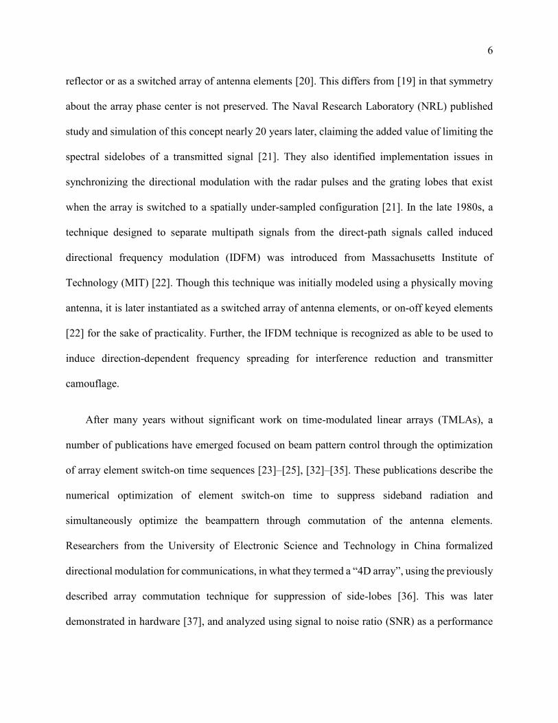
frequency band. This technique can enhance the performance of far field directive power beaming
compared to techniques proposed in the literature such as time domain switching [7], power
splitting [7]–[10], antenna switching [11], [12], and spatial switching [13], which seek an optimal
allocation of energy from a single transmitter to information and power harvesting circuits using
the available degrees of freedom. In contrast, our method enables the analog isolation of interfering
energy from the same time and frequency sub-space as the information signal. Thus, multiple,
spatially separated transmitters can reuse the same time and frequency sub-space to convey both
information and power to a single receiver. Consequently, our technique enables a denser
frequency re-use pattern and enables the re-use of the same spectrum for both communications
and wireless power transfer. The proposed method is the first implementation of directional
modulation for harvesting of co-channel interference.
In addition to simultaneous wireless information and power transfer when implemented
during reception, the proposed method can be applied during transmission to provide PHY-layer
secrecy for wireless communications devices. We can consider the proposed beamforming method
as overlaying direction-dependent modulation on a transmitted signal. Rather than minimizing the
signal energy transmitted away from the intended receiver, we selectively transform the energy to
natively provide PHY-layer secrecy in a broadcast channel. A novel contribution of this
dissertation is that the proposed method can be used to provide PHY-layer secrecy at a reduced
implementation cost compared to existing methods [5], [14]–[16], including in the computational
burden of steering vector formation and the analog hardware required to implement the
beamformer. Finally, the increased efficiency of the proposed beamforming method in terms of
the transmitter power sacrificed to implement the proposed beamforming method can enable an

13
overall increase in the sum-rate secrecy capacity in a wireless broadcast channel compared to the
currently accepted state-of-the-art [17], which is a major contribution of this work.
1.4 Dissertation Organization
The remainder of this dissertation is organized into three parts. In Chapter 2, we present a
novel phased array beamforming method to implement direction-dependent modulation. In
Chapters 3 and 4, we develop applications of the method developed in Chapter 2, intended for use
in wireless communications systems. In Chapters 5 and 6, we summarize simulation and
experimental results that demonstrate the feasibility and performance of the technique developed
in Chapter 2.
In Chapter 2, we design a time-varying array steering vector following a typical array
processing construct by defining a series of constraints that implement directional modulation. We
achieve this by designing a BPSK overlay modulation able to independently address two different
users, or two directions of interest. We introduce design methods to extend this technique to
additional users, additional directions of interest, and higher order PSK or QAM schema. To design
a passive beamformer, we impose a practical constraint that none of the elements in the steering
vectors can have net gain. Further, we define a design objective that maximizes the array response
in the directions of interest for overall implementation efficiency with the goal of outperforming
the implementation cost of Time-division multiplexing (TDM). Lastly, we formulate the
beamforming technique as a convex optimization problem, allowing for rapid computation of a
globally optimal solution with commercially-available solvers.

14
In Chapter 3, we study the application of the proposed beamforming technique for
simultaneous wireless information and power transfer. We implement the proposed beamforming
technique on receive to selectively modulate co-channel interference corrupting an information
signal. We explore methods to isolate the co-channel interference in the analog domain, such that
the energy contained in the interference can be harvested by the receiver. We compare this method
to publications, noting that it provides access to energy in the co-channel subspace, which has not
been previously proposed. Specifically, we note that this method can be used to re-use spectrum
for wireless information and power transfer without simply dividing resources, as is done in TDM,
frequency division multiplexing (FDM), or by power splitting.
In Chapter 4, we study the application of the proposed beamforming technique for physical
layer security in wireless communications systems. First, we implement the proposed
beamforming technique on transmit to selectively modulate the transmitted signal into a spoofed
signal in directions away from the intended receiver. We compare the achievable secrecy capacity
of this method to other wireless physical layer secrecy techniques, including the Artificial Noise
or Null-Space method. Given that the spoofed signal generated can be arbitrarily independent of
the intended signal, we explore the capability to transmit two completely independent signals to
two different users over a broadcast channel. We show that the proposed method can increase the
secrecy capacity for two users in a wireless broadcast channel beyond the currently accepted state-
of-the-art [17].
In Chapter 5, we summarize simulation results from various studies. First, we explore the
implementation cost of the proposed beamforming method, benchmarked by the average array
gain in the directions of interest subject to each of the steering vectors. We analyze various array

15
element spacing and geometries of receivers. Next, we present a summary of simulation results for
the achievable sum-rate secrecy capacity for two users in a wireless broadcast channel. Again, we
analyze various array element spacing and geometries of interest, and compare the results to the
currently accepted state-of-the-art, known as Dirty Paper Coding. We follow this with a summary
of simulation results for simultaneous wireless information and power transfer using the proposed
technique.
In Chapter 6, we summarize the procedures for and results of laboratory experimentation
carried out to validate the proposed technique. First, we describe at length the experimental setup,
plan, and rigorous calibration. Next, we provide a series of results with the express purpose of
1) verifying the quality of the direction-dependent modulation overlay using the proposed
beamforming technique and 2) measuring the implementation cost of the proposed beamforming
technique.
We conclude this dissertation in Chapter 7 by proposing future work, including further
analyses of the proposed method, additional applications of the proposed method, and practical
limitations of the proposed method. We suggest further analysis, linearization, and performance
characterization of the proposed beamforming method using non-uniform array layouts. We
recommend further exploration of additional applications, such as multi-rate, multiple access
communications. We also propose further analysis and experimentation investigating the practical
implementation of the proposed method, such as imperfect synchronization, imperfect hardware
implementation, and imperfect knowledge of the channel state information and channel model.

16
A Proposed Method for Directional
Modulation Using Beamforming
In this Chapter, we develop a novel method for directional modulation using phased arrays.
We design a set of time-varying array steering vectors following a typical array processing
construct by defining a series of constraints that control the direction-dependent modulation
overlay. First, we design a BPSK overlay modulation able to independently address two different
users located in two different directions relative to the array. Next, we design a passive beamformer
to implement the overlay modulation by imposing a practical constraint that none of the steering
vector elements can require net gain. Then, we introduce a design objective that maximizes the
array response in the directions of interest for overall implementation efficiency with the goal of
outperforming the implementation cost of other multiple access methods. We then formulate the
Chapter 2
17
beamforming technique as a convex optimization problem, allowing for rapid computation of
globally optimal steering vectors given the defined constraints. Lastly, we introduce design
methods to extend this technique to support additional users and higher order PSK or QAM
modulation schema.
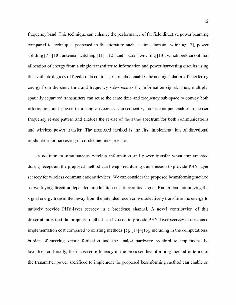
2.1 Array Processing Construct and Signal
Model
Invoking the array processing construct described in [1], we define the array manifold, 𝑽,
expressed as
𝑽 =
[ 𝑒
−𝑗�̂�0𝑇𝒑0
𝑒−𝑗�̂�0𝑇𝒑1
⋮
𝑒−𝑗�̂�0𝑇𝒑𝑁−1
𝑒−𝑗�̂�1𝑇𝒑0
𝑒−𝑗�̂�1𝑇𝒑1
⋮
𝑒−𝑗�̂�1𝑇𝒑𝑁−1
……⋱…
𝑒−𝑗�̂�𝑅−1𝑇 𝒑0
𝑒−𝑗�̂�𝑅−1𝑇 𝒑1
⋮
𝑒−𝑗�̂�𝑅−1𝑇 𝒑𝑁−1]
. (1)
The array manifold geometrically describes the array, including the locations of 𝑁 array elements
in a Cartesian coordinate system,
𝒑𝒏 = [
𝑥𝑛yn𝑧𝑛], (2)
and the array response toward 𝑅 different directions from the geometric center of the array.
Directions relative to the geometric center of the array are expressed as a unit vector based on
angles from the positive �̂� and �̂� axes (𝜃 and 𝜙, respectively), as follows:
18
�̂�𝒓 = [
sin(𝜃𝑟) cos (𝜙𝑟)
sin(𝜃𝑟) sin (𝜙𝑟)cos (𝜃𝑟)
]. (3)
One assumption underlying the proposed method is that all waves considered are plane waves
propagating in a homogeneous medium, such that the wavenumber corresponding to a direction
from the geometric center of the array is given by �̂�𝒓 =2𝜋
𝜆 �̂�𝒓, where 𝜆 is the operating
wavelength.
Continuing to follow a classical array processing construct [1], we exercise individual phase
and amplitude control by applying a complex weight at each element in the array. The vector of
complex weights at a given time 𝑡 is denoted by 𝒘(𝑡), called the weight vector or the steering
vector. We compute the time-varying complex channel transfer function between the array and a
point in the far field of the array in the direction �̂� under the array steering vector 𝒘 using the
appropriate column of 𝑽, 𝒗𝒌(�̂�), as
𝐻(𝒘, �̂�, 𝑡) = 𝒗𝑘𝐻(�̂�)𝐰(𝑡). (4)
We assume that the channel under a given steering vector, in each direction, for a given time
interval is static and ignore any other time-varying effects, such as those introduced by motion or
the environment. The channel transfer function 𝐻(𝒘, �̂�, 𝑡) is then manipulated as a function of
time by using multiple steering vectors to overlay a modulation on existing signals. The minimum
number of complex steering vectors, 𝑆, required to achieve the desired, independent modulation
depends on the number of directions of interest, 𝑅, the modulation format, the desired array
performance (i.e., array gain), and the modulation quality (e.g., modulation error ratio).

19
Throughout this chapter, we address the case where there are two directions of interest. We form
a matrix of 𝑆 steering vectors, 𝑾 ∈ ℂ𝑁×𝑆, as
𝑾 = [𝒘0 . . . 𝒘𝑆−1] = [
𝑤0,0𝑤0,1⋮
𝑤0,𝑁−1
……⋱…
𝑤𝑆−1,0𝑤𝑆−1,1⋮
𝑤𝑆−1,𝑁−1
] . (5)
We also explicitly assume a narrowband, line-of-sight channel model and ignore other effects,
such as propagation, since they could be compensated for separately.
2.2 Applying Directional Modulation
We seek to determine a matrix of array steering vectors, 𝑾, that can independently modulate
the channel 𝐻(𝒘, �̂�, 𝑡) in different directions, �̂�, without modifying the array manifold, 𝑽. The
minimum size of the array steering vector matrix, 𝑾, depends on the number of independently
controlled elements in the array, 𝑁, and the number of desired independently modulated directions,
𝑅. In this chapter, we specifically consider Binary Phase-Shift Keying (BPSK) modulation for
simplicity; however, this method is applicable to a variety of modulation schemes, including
higher-order M-ary phase-shift keying (PSK) modulation or quadrature amplitude modulation
(QAM).
For BPSK modulation and two directions of interest, denoted �̂�𝟎 and �̂�𝟏 (though �̂�𝒓 is a
wavenumber, we shall refer to it as a direction throughout this dissertation), we require a pair of
array steering vectors, denoted 𝒘𝟎 and 𝒘𝟏. In an abuse of notation, we denote the complex channel

20
in the direction �̂�𝑟 under steering vector 𝒘𝑠 as 𝑯𝑟,𝑠. We can express the 𝑅×𝑆 matrix of channels
by
𝑯 = [𝐻0,0 𝐻0,1𝐻1,0 𝐻1,1
] = 𝑽𝐻𝑾. (6)
For this example, we seek {𝒘𝟎, 𝒘𝟏} such that by alternating between steering vectors we can
selectively induce a symbol transition in the direction �̂�𝟎 independently from the direction �̂�𝟏.
Concisely, we seek {𝒘𝟎, 𝒘𝟏} such that
arg(𝒗𝑘𝐻(�̂�1)𝒘𝟏 ∗ (𝒗𝑘
𝐻(�̂�1)𝒘𝟎)∗) = 𝜋, and
arg(𝒗𝑘𝐻(�̂�0)𝒘𝟏 ∗ (𝒗𝑘
𝐻(�̂�0)𝒘𝟎)∗) = 0.
(7)
We can formalize two requirements to induce time-varying, overlay modulation in the arbitrary
direction �̂�𝟏 independently from the direction �̂�𝟎. First, we require the ability to achieve a phase
shift of approximately 𝜋 radians in the wireless channel in the direction �̂�𝟏 when switching from
array steering vector 𝒘𝟎 to array steering vector 𝒘𝟏, which can be written as a constraint expressed
as
|𝐻1,0 ∗ 𝑒𝑥𝑝 (−𝑗𝜋) − 𝐻1,1 | ≤ 휀, (8)
where 휀 denotes a parameter that controls the resulting modulation error ratio (MER), signal-to-
interference-plus-noise ratio (SINR), and degradation of the overall bit error rate. For the sake of
example, by choosing 휀 = 0.05 we can achieve a worst-case modulation error ratio of 26𝑑𝐵 for
the overlaid symbol and worst case modulation error ratio of −6𝑑𝐵 for the original symbol.

21
Simultaneously, we require a phase shift of approximately zero radian in the arbitrary
direction �̂�𝟎 when switching from array steering vector 𝒘𝟎 to array steering vector 𝒘𝟏, which can
be written as
|𝐻0,0 − 𝐻0,1| ≤ 휀. (9)
As above, a modest 휀 = 0.05 introduces a worst-case modulation error ratio of 26𝑑𝐵 to the
channel. With this pair of array steering vectors, 𝒘𝟎 and 𝒘𝟏, that can satisfy the stated
requirements, we are able to independently control BPSK modulation in the directions �̂�𝟏 and �̂�𝟎.
2.3 Efficiency of Directional Modulation
To practically implement directional modulation, we impose three constraints. First, we
allow for some maximum allowable implementation loss, as shown in (8) and (9). Second, we
require this proposed method to be implemented in a passive beamformer with fixed transmit
power using only phase delays and amplitude attenuation for each element, or |𝑾𝑛,𝑠| ≤ 1. This
model is physically accurate for communication systems which tend to operate in or near
saturation conditions, where phase embeds information, but no amplitude modulation is desired
for SNR considerations. This differs from other work that requires the array steering vectors to
be of unit magnitude [14] and work that requires the real and imaginary parts of the complex array
steering vectors to each be less than unit magnitude [53], which limits the available solution space
and results in steering vectors that enable directional modulation but at a significant cost to array
gain. Lastly, given that this is a broadcast system, we attempt to maximize the sum-rate capacity

22
without minimizing or zeroing capacity to a disadvantaged user. That is, we wish to maximize
the square of the norm of every wireless channel transfer function, |𝑯𝑟,𝑠|2.
The array steering vector matrix has a direct impact on the array beam patterns and resulting
link efficiency of the wireless communication system. We seek to constrain the array beam pattern
loss in each of the 𝑅 directions subject to each of the 𝑆 array weight vectors, such that the beam
pattern gain is greater than some factor 𝜉 of the maximum achievable beam pattern gain. The
square of the norm of the wireless channel transfer function, |𝑯𝑟,𝑠|2, is equivalent to the array
beam pattern in each direction, �̂�𝒓, subject to the array weight vector, 𝒘𝒔. Formally, we have
|𝑯𝑟,𝑠|2≥ 𝜉 ∗ max
𝑠,𝑟|𝑯𝑟,𝑠|
2. (10)
Many adaptive array processing techniques select an array steering vector to maximize the
output signal-to-noise ratio in a desired direction, typically for an intended receiver, and by
minimizing the array gain in undesired directions, typically towards interferers or unintended
receivers [1]. We consider the product of the array beam patterns in each direction under each
steering vector to ensure that there are no nulls placed under any array steering vector or in any
direction; however, we recognize that there are scenarios where the maximum achievable array
gain is not necessarily desired.

23
2.4 Array Steering Vector Formulation
2.4.1 Passive Beamformer
One contribution of this research to the current state-of-the-art consists of conforming the
objectives for directional modulation into a convex optimization problem to enable rapid selection
of the solution matrix of passive steering vectors 𝑾 using readily available solvers. First, for
practicality, 𝑾 is constrained such that each individual complex element weight, 𝑾𝑛,𝑠, has a norm
of less than or equal to unity. Thus, the array can be implemented with phase shifters and
attenuators and do not require additional gain. Formally, we define the convex subset Ω as
Ω = {𝑾: |𝑾𝑛,𝑠| ≤ 1, ∀𝑛 ∈ [0,…N − 1], ∀𝑠 ∈ [0,… , 𝑆 − 1]}. (11)
2.4.2 Time-Varying Beamformer
A summary of the operation for executing directional modulation is shown in the state diagram
in Figure 2.1. We seek an appropriate set of steering vectors, 𝑾, capable of independently
modulating the wireless channel transfer function in two different directions, �̂�𝒎 and �̂�𝒏. In the
case of two users, BPSK modulation, and the steering vector solution 𝑾 = [𝒘𝟎, 𝒘𝟏], we can
specify two different states for the array – one where the steering vector 𝒘𝟎 is applied, and one
where the steering vector 𝒘𝟏 is applied. As indicated in Figure 2.1 for the case of BPSK, we can
choose to or choose not to induce a symbol transition from either state in the direction �̂�𝒏, which
represents half of the required control. Since we have control of the transmitted data, 𝑑𝑚(𝑡), we

24
inherit the other half of the required control, i.e., by inverting 𝑑𝑚(𝑡) we can selectively modulate
the channel in the direction �̂�𝒎 instead of �̂�𝒏.
Figure 2.1: A state diagram of the array control system for directional modulation is shown. Here,
we specify two different states for the array – one where the steering vector 𝒘𝟎 is applied, and one
where the steering vector 𝒘𝟏 is applied. The desired modulation overlay induced in the directions
of interest, �̂�𝒎 and �̂�𝒏 are indicated for each transition for the two User case with BPSK overlay
modulation. The transitions shown in this state diagram represent half of the required control for
directional modulation; the other half of the required control is inherited by inverting the input
signal to the array.
2.4.3 Achieving Direction-Dependent Modulation
To achieve direction-dependent modulation, we define a set of constraints, given in (8) and
(9), as the convex subset Ψ, expressed as
Ψ =
{
𝑾:
[ 𝒗𝑘𝐻(�̂�𝐦) −𝒗𝑘
𝐻(�̂�𝐦)
−𝒗𝑘𝐻(�̂�𝒎) 𝒗𝑘
𝐻(�̂�𝐦)
𝒗𝑘𝐻(�̂�𝒏) 𝒗𝑘
𝐻(�̂�𝒏)
−𝒗𝑘𝐻(�̂�𝒏) −𝒗𝑘
𝐻(�̂�𝒏) ]
[𝒘𝟎𝒘𝟏] ≤ [
휀휀휀휀
]
}
. (12)
State 1
𝒘𝟏
State 0
𝒘𝟎
𝐻 ̂ , 1𝐻 ̂ , 0∗ −1
𝐻 ̂ , 1𝐻 ̂ , 0∗ 1
𝐻 ̂ , 0𝐻 ̂ , 0∗ = 1
𝐻 ̂ , 0𝐻 ̂ , 0∗ = 1
𝐻 ̂ , 1𝐻 ̂ , 1∗ = 1
𝐻 ̂ , 1𝐻 ̂ , 1∗ = 1
𝐻 ̂ , 0𝐻 ̂ , 1∗ = −1
𝐻 ̂ , 0𝐻 ̂ , 1∗ = 1

25
These modulation requirements can be easily extended to higher-order modulation and multiple
directions of interest by considering all the desired channel states and transitions. Examples for
higher-order modulation and additional directions are provided later in this Chapter.
Given the convex subset Ω ∩ Ψ, we form the objective function from the efficiency criteria
given in (10). We transform the requirement in (10) into a convex objective function to be
minimized as the negative sum of the of log of all the beam pattern responses in question. Formally,
we have
min(𝑓(𝑽,𝑾) )
𝑠. 𝑡. 𝑾 ∈ Ω ∩ Ψ , (13)
where 𝑓(𝑽,𝑾) = −∑ ln (|𝑯𝑟,𝑠|2)𝑠=0,…,𝑆−1
𝑟=0,…,𝑅−1 .
Lemma 1: Let 𝐖 ∈ ℂN×S and 𝑽 ∈ ℂN×R. If |𝑽𝑛,𝑟| = 1, ∀n ∈ [0,… , N − 1], ∀r ∈ [0,…R − 1], then
the function 𝑓(𝑽,𝑾) is convex. A proof of Lemma 1 can be found at the end of this Chapter.
2.4.4 Extension to 3 Directions of Interest
A summary of the operation for implementing BPSK directional modulation given three
arbitrary directions of interest is shown in the state diagram in Figure 2.2. We seek an appropriate
set of steering vectors, 𝑾, capable of independently modulating the wireless channel transfer
function in three different directions, �̂�𝟎, �̂�𝟏, and 𝒌𝟐. In the case of three users, BPSK modulation,
and the steering vector solution 𝑾 = [𝒘𝟎, 𝒘𝟏, 𝒘𝟐, 𝒘𝟑], we can specify four necessary states for
the array, where each state represents a different steering vector applied to the array. Each
transition between states is marked by a modulation overlay pair for the forward direction, [𝑥, 𝑦, 𝑧],

26
which is conjugated in the reverse direction. The modulation overlay pair is a simplified
representation of the modulation observed in the directions �̂�0 and �̂�1 when transitioning from
State a to State b, expressed as
[𝑥, 𝑦, 𝑧] = {
𝐻�̂�0, 𝐻�̂�0,𝑏∗ 𝑥 →𝑏
𝐻�̂�1, 𝐻�̂�1,𝑏∗ 𝑦 →𝑏
𝐻�̂�2, 𝐻�̂�2,𝑏∗ 𝑧 →𝑏
}. (14)
For the simplicity of Figure 2.2, we do not show the identity transition at each state. Further,
the state diagram represents half of the required control for independent messaging between the
transmitter and each of the receivers. Since we have control of the source data, we inherit the other
half of the required control without the need for additional states.
Figure 2.2: A state diagram of the array control system for directional modulation for the three
User case and BPSK overlay modulation is shown. Here, we specify four necessary states and
steering vectors for the array to overlay modulation in the directions of interest, �̂�𝟎, �̂�𝟏, and �̂�𝟐.
The transitions shown in this state diagram represent half of the required control for directional
modulation; the other half of the required control is inherited by inverting the input signal to the
array. The desired effect on the wireless channel transfer functions in each of the directions of
interest is given in (14).

27
From the state diagram in Figure 2.2, we seek to define a set of constraints similar to (12) that
can be used in (13) to determine a set of complex steering vectors that enable directional
modulation. We formalize these constraints to enable directional modulation in the three-User case
for BPSK modulation as the convex subset ΨR=3, expressed as
ΨR=3 =
{
𝑾:
{
{
[
𝑨⨂𝒗𝑘𝐻(�̂�0)
𝑩⨂𝒗𝑘𝐻(�̂�1)
𝑨⨂𝒗𝑘𝐻(�̂�2)
] [𝑤0𝑤1] ≤
[ 휀휀휀휀휀휀]
}
,
{
[
𝑨⨂𝒗𝑘𝐻(�̂�0)
𝑩⨂𝒗𝑘𝐻(�̂�1)
𝑩⨂𝒗𝑘𝐻(�̂�2)
] [𝑤0𝑤3] ≤
[ 휀휀휀휀휀휀]
}
,
{
[
𝑨⨂𝒗𝑘𝐻(�̂�0)
𝑨⨂𝒗𝑘𝐻(�̂�1)
𝑩⨂𝒗𝑘𝐻(�̂�2)
] [𝑤1𝑤3] ≤
[ 휀휀휀휀휀휀]
}
,
{
[
𝑨⨂𝒗𝑘𝐻(�̂�0)
𝑨⨂𝒗𝑘𝐻(�̂�1)
𝑩⨂𝒗𝑘𝐻(�̂�2)
] [𝑤0𝑤2] ≤
[ 휀휀휀휀휀휀]
}
,
{
[
𝑨⨂𝒗𝑘𝐻(�̂�0)
𝑩⨂𝒗𝑘𝐻(�̂�1)
𝑩⨂𝒗𝑘𝐻(�̂�2)
] [𝑤1𝑤2] ≤
[ 휀휀휀휀휀휀]
}
,
{
[
𝑨⨂𝒗𝑘𝐻(�̂�0)
𝑩⨂𝒗𝑘𝐻(�̂�1)
𝑨⨂𝒗𝑘𝐻(�̂�2)
] [𝑤2𝑤3] ≤
[ 휀휀휀휀휀휀]
}
}
}
, (15)
where 𝑨 = [1 −1−1 1
], 𝑩 = [−1 −11 1
], and 𝑿⨂𝒀 denotes the Kronecker product of the matrix 𝑿
and the matrix 𝒀. Though (15) is a compact representation, it is extremely similar in structure to
(12). The steering vectors for directional modulation varied according to the state diagram in
Figure 2.2 can be implemented in a beamformer for transmission or reception. A schematic
diagram showing one possible implementation of such a beamformer configured to transmit three
independent information signals in three different directions, �̂�0, �̂�1, and �̂�2 using the state
machine described in Figure 2.2 is shown in Figure 2.3.

28
Figure 2.3: Schematic diagram showing a beamformer implementing directional modulation by
time-varying the array steering vector. The beamformer behavior is controlled by a state machine
that is driven by the desired overlay modulation pattern, as described in Figure 2.2.
2.4.5 Extension to QPSK
For any given symbol constellation point in a Quadrature Phase Shift Keying (QPSK)
modulation constellation, we seek steering vectors capable of remapping that constellation point
to each of the other constellation points. The modulation constraints for QPSK require 4 steering
vectors or states to individually address each of these specific modulations, as shown in Figure
2.4. Each transition between states is marked by a modulation overlay pair for the forward
direction, [𝑥, 𝑦], which is conjugated in the reverse direction. The modulation overlay pair is a
simplified representation of the modulation observed in the directions �̂�0 and �̂�1 when transitioning
from State a to State b, expressed as
[𝑥, 𝑦] = {𝐻�̂�0, 𝐻�̂�0,𝑏
∗ 𝑥 →𝑏
𝐻�̂�1, 𝐻�̂�1,𝑏∗ 𝑦 →𝑏
} . (16)

29
We observe that from each state in Figure 2.4, the QPSK symbol transmitted in the direction
�̂�0 can be remapped to any QPSK symbol in the direction �̂�1 by varying the steering vector. Similar
state diagrams can be constructed for modulation schemes requiring manipulation of amplitude
and phase, such as 16-QAM. Introducing relative rotation and scale to the set of linear inequality
constraints in (12) will remain affine and preserve the convexity of the subset.
Figure 2.4: A state diagram of the array control system for directional modulation for the two User
case and QPSK overlay modulation is shown. Here, we specify four necessary states and steering
vectors for the array to overlay modulation in the directions of interest, �̂�𝟎 and �̂�𝟏. The transitions
shown in this state diagram represent half of the required control for directional modulation; the
other half of the required control is inherited by inverting the input signal to the array. The desired
effect on the wireless channel transfer functions in each of the directions of interest is given in
(16).
From the state diagram in Figure 2.4 we seek to define a set of constraints similar to (12) that
can be used in (13) to determine a set of complex steering vectors that enable directional
modulation. We formalize these constraints to enable directional modulation in the two-User case
for QPSK modulation as the convex subset Ψ𝑄𝑃𝑆𝐾, expressed as
1,−1
1,−𝑗1, 𝑗
1, 𝑗
1, −𝑗
1,−1
1,1
1,11,1
1,1
State 3
𝑤3
State 0
𝑤0
State 1
𝑤1State 2
𝑤2
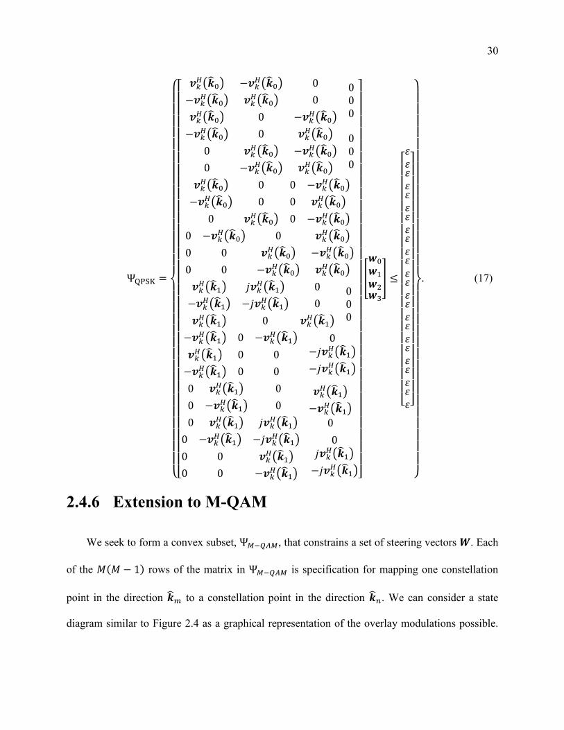
30
ΨQPSK =
{
[ 𝒗𝑘𝐻(�̂�0) −𝒗𝑘
𝐻(�̂�0) 0
−𝒗𝑘𝐻(�̂�0) 𝒗𝑘
𝐻(�̂�0) 0
𝒗𝑘𝐻(�̂�0) 0 −𝒗𝑘
𝐻(�̂�0)
000
−𝒗𝑘𝐻(�̂�0) 0 𝒗𝑘
𝐻(�̂�0)
0 𝒗𝑘𝐻(�̂�0) −𝒗𝑘
𝐻(�̂�0)
0 −𝒗𝑘𝐻(�̂�0) 𝒗𝑘
𝐻(�̂�0)
000
𝒗𝑘𝐻(�̂�0) 0 0
−𝒗𝑘𝐻(�̂�0) 0 0
0 𝒗𝑘𝐻(�̂�0) 0
−𝒗𝑘𝐻(�̂�0)
𝒗𝑘𝐻(�̂�0)
−𝒗𝑘𝐻(�̂�0)
0 −𝒗𝑘𝐻(�̂�0) 0
0 0 𝒗𝑘𝐻(�̂�0)
0 0 −𝒗𝑘𝐻(�̂�0)
𝒗𝑘𝐻(�̂�0)
−𝒗𝑘𝐻(�̂�0)
𝒗𝑘𝐻(�̂�0)
𝒗𝑘𝐻(�̂�1) 𝑗𝒗𝑘
𝐻(�̂�1) 0
−𝒗𝑘𝐻(�̂�1) −𝑗𝒗𝑘
𝐻(�̂�1) 0
𝒗𝑘𝐻(�̂�1) 0 𝒗𝑘
𝐻(�̂�1)
000
−𝒗𝑘𝐻(�̂�1) 0 −𝒗𝑘
𝐻(�̂�1)
𝒗𝑘𝐻(�̂�1) 0 0
−𝒗𝑘𝐻(�̂�1) 0 0
0−𝑗𝒗𝑘
𝐻(�̂�1)
−𝑗𝒗𝑘𝐻(�̂�1)
0 𝒗𝑘𝐻(�̂�1) 0
0 −𝒗𝑘𝐻(�̂�1) 0
0 𝒗𝑘𝐻(�̂�1) 𝑗𝒗𝑘
𝐻(�̂�1)
𝒗𝑘𝐻(�̂�1)
−𝒗𝑘𝐻(�̂�1)
0
0 −𝒗𝑘𝐻(�̂�1) −𝑗𝒗𝑘
𝐻(�̂�1)
0 0 𝒗𝑘𝐻(�̂�1)
0 0 −𝒗𝑘𝐻(�̂�1)
0𝑗𝒗𝑘𝐻(�̂�1)
−𝑗𝒗𝑘𝐻(�̂�1)]
[
𝒘0𝒘1𝒘2𝒘3
] ≤
[ 휀휀휀휀휀휀휀휀휀휀휀휀휀휀휀휀휀휀휀휀휀휀휀휀]
}
. (17)
2.4.6 Extension to M-QAM
We seek to form a convex subset, Ψ𝑀−𝑄𝐴𝑀, that constrains a set of steering vectors 𝑾. Each
of the 𝑀(𝑀 − 1) rows of the matrix in Ψ𝑀−𝑄𝐴𝑀 is specification for mapping one constellation
point in the direction �̂�𝑚 to a constellation point in the direction �̂�𝑛. We can consider a state
diagram similar to Figure 2.4 as a graphical representation of the overlay modulations possible.

31
Rather than specifying the absolute location of the desired constellation point in the direction �̂�𝑛,
we specify the relative mapping between the two constellation points as a rotation and scale in the
matrix in Ψ𝑀−𝑄𝐴𝑀, rather than just the rotation, as in Ψ. The subset Ψ𝑀−𝑄𝐴𝑀 would still be affine
and convex. For QAM, we would also modify the objective function to only consider the array
response of the corner constellation points.
We recognize that the convex subset Ψ𝑀−𝑄𝐴𝑀 would become particularly large. At most, we
would need a library of 𝑀2 steering vectors to enable us to remap any of 𝑀 transmitted
constellation points to any other constellation point. By recognizing that constellation mapping
pairs separated by identical translations can employ the same steering vector, we can reduce the
number of steering vectors needed to 𝑀(𝑀−1)
2. Due to the need for the modulus operator, the number
of rows in the matrix of Ψ𝑀−𝑄𝐴𝑀 is 𝑀(𝑀 − 1).
2.4.7 Selection of the Inequality Constraint Parameter ε
The selection of the parameter 휀 in the linear inequality constraints for directional modulation
as in (12), (15), and (17), is not only critical to the performance in terms of achieved modulation
error ratio, but also affects the achievable array gain. We recognize that it is not necessary for the
inequality constraint parameter to be applied uniformly across each inequality constraint; however,
we do so for the ease of analysis, and the gains achieved by individually tuning this parameter per
user is left as a topic for future research.
The set of inequality constraints, Ψ, describes the overlay modulation we seek to achieve.
These constraints are critical to directional modulation to achieve independent, confidential links
to multiple users as opposed to simply increasing the bit error rate everywhere but the intended

32
direction as in [6], [31], [54]. Further, we note that if we impose equality constraints rather than
inequality constraints for the overlay modulation as in [14], [29], [53], a solution may not exist
that satisfies all the constraints . This would also necessitate an iterative algorithmic approach to
determining the steering vectors, which is unattractive due to the time required to converge to a
solution and the non-convex nature of the optimization.
In the set of inequality constraints, Ψ, we can consider the parameter 휀 as a surrogate for the
modulation error ratio, as shown in Figure 2.5. The arbitrary received signal subject to the channel
transfer function 𝐻 is shown. The channel transfer function is manipulated by updating the array
steering vector, and represented as 𝐻𝑏. We are concerned principally with the new measured
symbol relative to the original symbol, shown as 𝐻 ∗ 𝐻𝑏∗, and note that 𝐻 can also represent the
desired symbol rather than the actual symbol without loss of generality. We specify 휀 as the
maximum allowable norm of the distance between 𝐻 and 𝐻 ∗ 𝐻𝑏∗. Clearly, 휀 should be small
relative to the SNR of the measured symbol to avoid unwanted symbol errors or an observable
modulation structure even without symbol transition.

33
Figure 2.5: Graphical representation of the control parameter ε, a surrogate for the modulation
error ratio possible in the set of inequality constraints, Ψ, for directional modulation. The channel
transfer functions resulting from a set of steering vectors are given by 𝐻 and 𝐻𝑏. We are
concerned principally with the resulting overlay modulation, 𝐻 ∗ 𝐻𝑏∗, and note that 𝐻 can also
represent the desired symbol rather than the actual symbol without loss of generality. We specify
ε as the maximum allowable norm of the distance between 𝐻 and 𝐻 ∗ 𝐻𝑏∗, which allows us to
quantify and specify a worst-case increase in bit error rate resulting from directional modulation.
We can quantitatively relate the control parameter 휀 to a worst-case reduction in SNR and
worst-case bit error rate, as follows. The well-known probability of bit error for a BPSK-modulated
signal with energy per bit, 𝐸𝑏, in additive white Gaussian noise with power spectral density 𝑁0 is
given by [55] 𝑃𝑏 (𝐸𝑏
𝑁0) = 𝑄 (√2
𝐸𝑏
𝑁0), where 𝑄(𝑥) is the statistical Q-function. Phase errors, 𝜙,
possibly resulting from imperfect synchronization or multipath affect the energy per bit to noise
power spectral density ratio (𝐸𝑏/𝑁0) and thus the probability of bit error by
𝑃𝑏 (𝐸𝑏𝑁0|𝜙) = 𝑄(√2
𝐸𝑏𝑁0∗ cos(𝜙)). (18)
Selection of the parameter 휀 will similarly affect the probability of bit error by reducing the
effective overall 𝐸𝑏/𝑁0, resulting from a decreased received bit energy, but unchanged noise

34
power spectral density. The expected overall probability of bit error given two channel transfer
functions 𝐻 and 𝐻𝑏, assuming |𝐻 | > |𝐻𝑏| and knowing the fraction of time the channel transfer
function can be characterized as 𝐻 as opposed to 𝐻𝑏, 𝑃𝐻𝑎, can be computed as
𝑃𝑏 = 𝑃𝐻𝑎𝑄(√2𝐸𝑏,𝐻𝑎𝑁0
) + (1 − 𝑃𝐻𝑎) 𝑄 (√2𝐸𝑏,𝐻𝑎𝑁0
(|𝐻 |
2 + |𝐻𝑏|2
2|𝐻 |2−
휀2
2|𝐻 |2)). (19)
Here, we note that if only one channel, 𝐻 is used, this reduces to the traditional bit error rate
calculation. If we assume an equal use of the BPSK symbols {−1,+1}, such that 𝑃𝐻𝑎 = 𝑃𝐻𝑏 =
0.5, we observe that the overall 𝐸𝑏/𝑁0 is penalized by any magnitude imbalance between the
channels (i.e., |𝐻𝑏|2 < |𝐻 |
2) and the magnitude of the vector difference between channels (i.e.,
휀2 = |𝐻 − 𝐻𝑏|2). For a given 휀, the worst-case reduction in 𝐸𝑏/𝑁0 is realized when 𝐻 and 𝐻𝑏
are collinear. The penalty term above reduces to a simple scaling, given by
|𝐻𝑏|
|𝐻 |= 1 −
휀
|𝐻 | (20)
By specifying the fixed parameter 휀 rather than a relative quantity, we are able to maintain the
convexity of (13). The worst case reduction in 𝐸𝑏/𝑁0 is less than 0.5𝑑𝐵 for 휀 = 0.05 ∗ |𝐻 | for
typical operating ranges of BPSK with a bit error rate of less then 10−3 (6𝑑𝐵 < 𝐸𝑏/𝑁0 < 12𝑑𝐵),
as shown in Figure 2.6. If we are able to normalize the measured channel state information, prior
to executing the optimization in (13), we can specify the fixed parameter 휀 without loss of
generailty. Here, we are particularly concerned with efficiency, and are interested in cases where
|𝐻𝑏| and |𝐻 | are within 3𝑑𝐵 of the peak achievable channel transfer function. As such, we choose
휀 = 0.05 as the design parameter such that the loss due to modulation error.

35
Figure 2.6: Plot of curves showing the worst-case increase in bit error rate under the channel
transfer function 𝐻𝑏 based on the bit energy to noise power spectral density ratio, 𝐸𝑏/𝑁0, of 𝐻
and the directional modulation constraint control parameter 휀. We observe that the worst-case
reduction in 𝐸𝑏/𝑁0is less than 0.5𝑑𝐵 for 휀 = 0.05 ∗ |𝐻 | for typical operating ranges of BPSK
with a bit error rate of less then 10−3 (6𝑑𝐵 < 𝐸𝑏/𝑁0 < 12𝑑𝐵 ).
2.4.8 Proof of Lemma 1
Proof of Lemma 1: Let 𝐰𝐬 ∈ ℂN and 𝐯𝐤(�̂�𝐫) ∈ ℂ
N. The magnitude of the channel is given by
𝑔(𝒘𝒔∗, 𝒘𝒔): ℂ
𝑁 → ℝ, where
𝑔(𝒘𝒔∗, 𝒘𝒔) = |𝑯𝑟,𝑠|
2= 𝐰𝐬
𝐻𝐯𝐤(�̂�𝐫)𝐯𝐤𝑯(�̂�𝐫)𝐰𝐬. (21)

36
Making use of Wirtinger derivatives, we can easily show that the gradient of 𝑔(𝒘𝒔∗, 𝒘𝒔) is given
by
∇𝒘𝒔∗𝑔(𝒘𝒔∗, 𝒘𝒔) = 𝐯𝐤(�̂�𝐫)𝐯𝐤
𝑯(�̂�𝐫)𝐰𝐬, (22)
and the Hessian of 𝑔(𝒘𝒔∗, 𝒘𝒔) is given by
∇𝒘𝒔∗,𝒘𝒔2 𝑔(𝒘𝒔
∗, 𝒘𝒔) = 𝐯𝐤(�̂�𝐫)𝐯𝐤𝑯(�̂�𝐫) = 𝑹𝑟. (23)
To prove that 𝑓(𝑽,𝑾) is convex, we can show that 𝑑(𝒘𝒔∗, 𝒘𝒔) = ln (|𝐰𝐬
𝐻𝐯𝐤(�̂�𝐫)𝐯𝐤𝑯(�̂�𝐫)𝐰𝐬|
2) is
concave by examining the derivatives, since convexity is preserved under nonnegative weighted
sums [56]. Since 𝑑(𝒘𝒔∗, 𝒘𝒔) = ℎ(𝑥) ∘ 𝑔(𝒘𝒔
∗, 𝒘𝒔) is a composite function, the second derivative is
given by
𝑑′′(𝒘𝒔∗, 𝒘𝒔) = ℎ
′′(𝑔(𝒘𝒔∗, 𝒘𝒔)) (∇𝒘𝒔∗𝑔(𝒘𝒔
∗, 𝒘𝒔))𝟐
+
ℎ′(𝑔(𝒘𝒔∗, 𝒘𝒔))∇𝒘𝒔∗,𝒘𝒔
2 𝑔(𝒘𝒔∗, 𝒘𝒔) .
(24)
It follows from (24) that 𝑑(𝒘𝒔∗, 𝒘𝒔) is concave if ℎ(𝑔(𝒘𝒔
∗, 𝒘𝒔)) is concave and nondecreasing,
and 𝑔(𝒘𝒔∗, 𝒘𝒔) is concave, which is the case here. The non-negative eigenvalues of
∇𝒘𝒔∗,𝒘𝒔2 𝑔(𝒘𝒔
∗, 𝒘𝒔) indicate that it is positive semidefinite. Upon closer inspection, we observe that
𝑑′′(𝒘𝒔∗, 𝒘𝒔) = −
(𝑹𝑟𝐰𝐬)𝐻𝑹𝑟𝐰𝐬
(𝐰𝐬𝐻𝑹𝑟𝐰𝐬 )
2 +𝑹𝑟
𝐰𝐬𝐻𝑹𝑟𝐰𝐬
, (25)
which is always negative since the norm of the elements of the matrix 𝑹𝑟 = 𝐯𝐤(�̂�𝐫)𝐯𝐤𝑯(�̂�𝐫) are
always equal to 1. Therefore, since 𝑑(𝒘𝒔∗, 𝒘𝒔) is concave, 𝑓(𝑽,𝑾) is convex.
37
Simultaneous Wireless Information
and Power Transfer Using Directional
Modulation
The current state of spectrum regulation in the Americas, Europe, and Asia has herded many
wireless communications devices into crowded bandwidths [57]. As such, it is quite possible that
a significant amount of energy available for harvesting exists in the same time and frequency sub-
spaces as the desired signal. We apply the proposed beamforming method for directional
modulation described in Chapter 2 to enable a device to harvest interfering energy that is spatially
separated from an information signal, but within the same time and frequency subspaces. The
proposed thus enables simultaneous wireless information and power transfer with high system
spectral efficiency.
Chapter 3

38
3.1 Overview
First, we apply the proposed beamforming method to a receiver harvesting energy from co-
channel interferers. Early research of methods for harvesting microwave electromagnetic energy
using antennas with rectifiers [58] was focused on delivering energy to aerospace vehicles. The
so-called “rectennas” placed rectifiers with a matching circuit directly onto the antennas [59] and
were dedicated to maximizing the efficiency of wireless power transfer from the transmitter to the
receiver. A simple way for wireless communications devices to harvest microwave
electromagnetic energy while communicating is to separate the desired signal energy from any
noise and interference energy. Signals can be designed to occupy predictable time and bandwidth;
therefore, simple switches and multiplexers can divert energy from unnecessary time and
frequency sub-spaces to an energy-harvesting subsystem. Unfortunately, any energy within the
desired time and frequency sub-space that is not related to the desired signal can degrade
performance and is difficult to divert and harvest, requiring strict synchronization across the
communications system. Any interfering energy that is spatially separated from the desired signal
can be nulled to minimize the effect on the desired signal, but then cannot be harvested.
Given the reciprocal nature of array beamforming, we implement the proposed directional
modulation method during reception. In this application, we enable the separation of signal energy
from interfering energy within the same time and frequency sub-space in the analog domain, such
that the interfering energy can be separated and harvested for power while simultaneously
decoding the information-bearing signal. The proposed method enables selective spectral
manipulation of co-channel interference without corrupting the desired signal. Specifically, we

39
frequency modulate interfering signals far enough out of band such that they can be easily
harvested using a passive diplexer as shown in Figure 3.1. Using a diplexer, we can then isolate
the information-bearing signal from a large fraction of the energy from an interferer, such as a
wireless power transfer system, which now occupies a different frequency band.
Figure 3.1: Schematic diagram showing a beamformer implementing directional modulation by
time-varying the array steering vector. The output of the beamformer is connected to a diplexer
that diverts in-band frequencies containing the information signal to a demodulator and now out-
of-band frequencies carrying the power transfer signal to an energy harvesting circuit.
The proposed directional modulation method would enable communications systems with
designed layouts (such as mobile wireless communications systems served by fixed base stations)
to reuse the same frequencies for information and for power transfer, so long as they are spatially
separated. This can be easily implemented, for example, in a cellular sector as shown in Figure
3.2. The sector is served by three base stations, each with two antennas providing service with a
simple frequency re-use scheme to provide wireless power transfer in addition to information
transfer. A user inside the sector can use the proposed beamforming method to separate the
information and wireless power transfer signals on any frequency since they will be spatially
separated. Depending on the specific frequency allocation, it is possible to access more than one
frequency simultaneously.

40
Figure 3.2: Example of a cellular sector served by three base stations, each with an antenna
providing service to the sector. The frequency allocations are planned such that the base stations
serving a sector do not interfere with each other. This notional layout also shows a simple scheme
to re-use these frequencies to provide wireless power transfer. A user inside the sector can use the
proposed beamforming method to use any of the frequencies available for information and wireless
power transfer since they are spatially separated. Depending on the specific frequency allocation,
it is possible to access more than one frequency simultaneously.
3.2 Prior Art
The proposed directional modulation method can be applied to enhance far field directive
power beaming, which is able to transfer several orders of magnitude more power than far field
ambient scavenging techniques [60]–[62], at ranges several times further than near field power
transfer [62]. Other far field directive power beaming techniques proposed in the literature such as
time domain switching [7], power splitting [7]–[10], antenna switching [11], [12], and spatial
switching [13] seek an optimal allocation of energy from a single transmitter to information and
power harvesting circuits using available degrees of freedom. Allocations for far field directive
power beaming techniques have been proposed that consider the security needs of wireless
information and power transfer systems [63].
AB
C
C
BA
Base Station
Sector Antenna
Wireless Power Transfer
Signal at Frequency C
Information Signal at
Frequency B
C
B

41
In contrast, the proposed method enables the isolation and harvesting of interfering energy
from the same time and frequency sub-space as the information signal. Thus, multiple, spatially
separated transmitters can occupy the same time and frequency sub-space, and convey both
information and power to a single receiver. Consequently, our method enables a denser frequency
re-use pattern in communications systems while providing energy to mobile devices. Additionally,
it enables a system to operate within a narrower frequency allocation by re-using the same
spectrum for both communications and wireless power transfer.
3.3 Harvesting Energy from Co-channel
Interferers Using Beamforming
We apply the proposed method to develop a new array beamforming technique for
simultaneous wireless information and power transfer for communications devices based on
concepts of direction-dependent modulation. The proposed method is formulated as a convex
optimization problem, which reduces the computational burden of steering vector formation
compared to other methods [14], [15]. It is also constrained to be implemented as a passive
beamformer, in contrast to other techniques [16], [53]. Simulation and experimentation showing
both the proof of concept and potential performance of the proposed method is shown in Chapters
5 and 6.

42
3.3.1 Signal Model
Our received signal model, 𝒙(𝑡), consists of the sum of a plane wave information signal of
interest in the direction �̂�𝒔, a plane wave wireless power transfer signal in the direction �̂�𝒑, and
isotropic noise 𝜂. Each of these signals occupies the same time and frequency sub-space, and is
given by 𝒙(𝑡) = 𝑏𝑠𝒗𝒌(�̂�𝒔) + 𝑏𝑝𝒗𝒌(�̂�𝒑) + 𝜂 where 𝑏𝑠 and 𝑏𝑝 are arbitrary scalars. We seek to
apply an overlay modulation to the power transfer signal independent of the desired information
signal using a time-varying array steering vector. This signal model assumes an otherwise static
channel during the time scales of interest. The array output is given by 𝑦(𝑡) = 𝒙𝐻(𝑡)𝒘(𝑡). In the
case of overlaying a BPSK modulation, we identify two steering vectors, 𝒘0 and 𝒘1, such that the
transition between 𝒗𝑘𝐻(�̂�𝑝)𝒘0 and 𝒗𝑘
𝐻(�̂�𝑝)𝒘1 induces a sufficient phase shift while the transition
between 𝒗𝑘𝐻(�̂�𝑠)𝒘0 and 𝒗𝑘
𝐻(�̂�𝑠)𝒘1 does not. Furthermore, we must sufficiently modulate the
power transfer signal in frequency such that it can be harvested while preserving the desired
information signal.
Once modulated in frequency, the power transfer signal can be isolated using a diplexer and
diverted to the energy harvesting circuit. To maintain a usable efficiency, we only consider
beamforming using phase delays and attenuation, such that the power transfer signal harvesting
system is comprised of the antenna array, a matching network, a passive phase delay device, an
attenuator, a combiner, and the energy harvesting circuit. We select an optimal set of steering
vectors per (13) and predictably time-vary them to achieve the desired modulation in separate
directions. Given that this is an array processing technique that can be added to existing energy

43
harvesting circuitry, practical constraints such as transmission efficiency, path loss, and receive
circuit efficiency have not been taken into consideration.
3.3.2 Spectral Manipulation of Co-channel Interference
From (13) we have identified an optimal pair of steering vectors to modulate the wireless
power transfer signal without distorting the desired information signal, while maintaining adequate
array gain in both directions. We then vary the steering vector between 𝒘𝟎 and 𝒘𝟏 to overlay a
phase-shift keying (PSK) modulation only to the wireless power transfer signal. Throughout this
paper, we assume that both transmitted signals—the information-bearing signal and the wireless
power transfer signal—are BPSK-modulated signals occupying the same bandwidth. In the case
where there is bandwidth mismatch, system parameters should be designed based on the wider
bandwidth. The power spectral density of BPSK-modulated signals is given by [64]
𝑃𝐵𝑃𝑆𝐾(𝑓) = 2𝐸𝑏 (sin (
𝜋𝑓𝑓𝑐)
𝜋𝑓𝑓𝑐
)
2
, (26)
where 𝐸𝑏 is the bit energy, 𝑓 is the signal center frequency, and 𝑓𝑐 is the modulation chip rate. For
an un-spread BPSK-modulated signal, the modulation chip rate is equal to the symbol rate.
There are well known PSK modulation sequences and rates that can be applied to manipulate
the signal power spectrum. For example, we can apply a direct sequence spread spectrum (DSSS)
modulation by applying a BPSK-modulated waveform of a pseudo-random sequence at a
modulation chip rate significantly higher than the symbol rate, which spreads the typical sinc-
shaped power spectrum and reduces the peak power spectral density as shown in Figure 3.3.

44
Knowing that we seek to minimize the power spectral density about the carrier frequency within
the information bandwidth and maximize the power transferred outside the information bandwidth,
we employ Binary Offset Carrier (BOC) modulation, which has been designed specifically for
broadcast scenarios of multiple signals sharing the same time-frequency subspace [65].
3.3.3 Binary Offset Carrier (BOC) Modulation
Binary Offset Carrier (BOC) modulation was designed for spectrum re-use among
conventional PSK-modulated signals [65] and is currently employed on satellite navigation
systems to enable signals to effectively share spectrum [66]. The power spectral density of a BOC-
modulated signal using the chip rate 𝑓𝑐 and subcarrier frequency 𝑓𝑠, denoted 𝐵𝑂𝐶(𝑓𝑠, 𝑓𝑐), is given
by [65]
𝑃𝐵𝑂𝐶(𝑓𝑠,𝑓𝑐)(𝑓) = 𝑓𝑐 (sin (
𝜋𝑓2𝑓𝑠) sin (
𝜋𝑓𝑓𝑐)
𝜋𝑓𝑐𝑜𝑠 (𝜋𝑓2𝑓𝑠)
)
2
. (27)
The power spectral density of a BPSK-modulated signal is compared to that of a spread
spectrum-modulated signal and that of a BOC(10,2)-modulated signal in Figure 3.3. It is clear by
inspection that we can increase the instantaneous bandwidth of the BPSK-modulated signal by
modulating the signal at a rate faster than the symbol rate. The ratio of the maximum chipping or
subcarrier rate to the symbol rate is known as the spreading factor; the latter is a measure of
intercept probability as well as a robustness measure against multipath fading. We can uniformly
spread the signal energy across a wide bandwidth by using direct sequence spread spectrum

45
(DSSS) modulation or deliberately shift the vast majority of the signal located within the
information bandwidth outside that bandwidth using BOC modulation.
Figure 3.3: Comparison of theoretical spectra of BPSK modulation, spread spectrum BPSK
modulation, and BOC(10,2) modulation, at the same center frequency. The spread spectrum BPSK
chipping rate and the BOC(10,2) subcarrier frequency in this example are a factor of 5 higher than
the BPSK symbol rate.
3.3.4 Preservation of the Desired Signal and
Synchronization
The proposed beamforming method is designed to allow simultaneous wireless information
and power transfer from signals that share the same time and frequency sub-space. The proposed
method selectively modulates the wireless power transfer signal out-of-band, but must not
irreversibly distort the information-bearing signal. As such, the array steering vector optimization

46
criteria given in (13) reflect a requirement of a distortionless response in the direction of the
information signal.
The distortionless response criteria in (13) removes the requirement for the system to
synchronize to the information signal; however, to effectively overlay the BOC modulation, the
receiver must be synchronized to the wireless power transfer signal. Assessing the sensitivity of
BOC modulation to the subcarrier misalignment is beyond the scope of this work. Here, we assume
that the receiver is able to synchronize to the wireless power transfer signal through a search
algorithm assisted by global timing, such as the one provided by the Global Positioning System
(GPS).
Further, the proposed beamforming method relies on knowledge of the incoming direction of
both the information signal and the wireless power transfer signal. The directions of arrival should
be estimated as part of the receiver synchronization (signal acquisition and tracking). Multiple
signal classification is outside the scope of this paper; however, integrating direction-of-arrival
estimation into the beamformer weight selection process is a topic recommended for future
research.
47
Increased Secrecy Capacity Using
Directional Modulation
The proposed beamforming method can improve the performance of Internet of Things (IoT)
systems by increasing the overall secrecy capacity of a wireless broadcast system without
increasing the size, weight, or power consumption of IoT devices. Unlike traditional beamforming
techniques [1], [2] which focus energy in the direction of an intended receiver and minimize the
total energy transmitted in the direction of an eavesdropper, the proposed method uses time-
varying beamforming to induce physical layer symbol transitions in the energy transmitted in the
direction of an eavesdropper, resulting in an entirely new “cover” signal to mask the original
message. This is accomplished by overlaying a direction-dependent modulation onto the
transmitted signal. This technique, called directional modulation, has been proposed previously
for physical layer security when considering a single user and one or more eavesdroppers by
Chapter 4

48
sufficiently increasing the signal-error-vector magnitude in the direction of the eavesdroppers [6],
[14], [26], [30], [52], [67], [68]. Other techniques, such as the artificial noise method or null-space
method for multiple-input single-output (MISO) systems are formulated to do the same [5]. With
the exception of [67], these publications aim to increase the overall secrecy capacity of the system
by preventing the eavesdropper from receiving a message rather than increasing the overall
capacity of the system. This work is the first to consider directional modulation in a broadcast
scenario and increases the achievable secrecy capacity in a wireless broadcast channel by
increasing the sum-rate wireless broadcast channel capacity and increasing the PHY-layer secrecy
of the transmitted signals.
PHY-layer secrecy in wireless communications systems tends to leverage a simple rule of
thumb: increasing the signal-to-interference-plus-noise ratio (SINR) of a transmission decreases
the rate of bit errors at the receiver, and vice versa [69]. As such, Eavesdroppers desire the
maximum possible SINR for signals intended for other receivers. Cognizant communications
systems might reduce the power transmitted in the directions of suspected eavesdroppers in an
attempt to increase the eavesdroppers received bit error rate and mask as much of the transmission
as possible [2]. Unfortunately, many techniques exist to increase the SINR of a received signal,
possibly to an intelligible level, including increasing the antenna size or decreasing the distance
between the transmitter and the eavesdropper [70].
If we assume that an Eavesdropper is not sufficiently within the line-of-sight between a
transmitter and a receiver pair such that the array manifold and wireless channel between the
transmitter and the eavesdropper is different than the array manifold and wireless channel between
the transmitter and receiver, then directional modulation may be applied to provide additional
49
PHY-layer secrecy. Recent research has described approaches to time-varying beamforming
techniques to enable directional modulation for the purposes of PHY-layer secrecy [6], [14], [26],
[30], [36], [52]. These techniques attempt to intentionally modulate the amplitude and phase of
transmitted symbols in directions away from the intended receiver, thus randomly inducing
additional bit errors in the transmitted signal at the PHY-layer. A sufficient rate of these bit errors
would reduce the signal received by an eavesdropper to a random string of bits lacking any
meaningful information.
Given knowledge of the direction from the array toward the eavesdropper, the proposed
beamforming method can be used to overlay a second information signal in the direction of the
eavesdropper that is completely independent of the genuine information signal. The proposed
method independently modulates the array manifold and consequently, the wireless channel
between the transmitter and the eavesdropper and the wireless channel between the transmitter and
the receiver. Rather than simply reducing the signal power in the direction of the eavesdropper and
relying on either the eavesdropper’s internal noise or external noise to induce sufficient bit errors,
the eavesdropper can be spoofed by completely replacing the genuine signal with an incorrect but
valid information signal, because the proposed method is capable of arbitrary modulation at the
PHY-layer. Further, as a PHY-layer technique, directional modulation can be applied independent
of other security protocols at other layers of the Open Systems Interconnection (OSI) model,
including encryption.

50
4.1 Disguising Transmissions for Physical Layer
Secrecy
Consider a Base Station transmitter with 𝑁 antennas communicating with a legitimate user in
the direction �̂�𝑚, known as User 0. There is an Eavesdropper in the direction �̂�𝑛, known as User
1, as shown in Figure 4.1. We let 𝑁 = 2 and restrict the transmit power of the Base Station to 𝑃𝑇.
We assume that both User 0 and User 1 are externally noise limited with noise level 𝜎𝑚2 and 𝜎𝑛
2,
respectively.
Figure 4.1: Diagram of Base Station transmitter array servicing a User (User 0) spatially separated
from an Eavesdropper (User 1). The Base Station possesses two messages: a genuine signal, 𝑑𝑚,
intended for User 0 and a spoofed signal, 𝑑𝑛, intended for User 1. Due to the broadcast nature of
the Base Station and expected wireless channels, we expect that both messages are perceptible by
their respective unintended receivers.
The data intended for User 0 in the direction �̂�𝒎 is denoted by 𝑑𝑚(𝑡). Arbitrarily independent
data intended for the Eavesdropper (User 1) in the direction �̂�𝒏 is denoted by 𝑑𝑛(𝑡). A typical

51
array modulates 𝑑𝑚(𝑡) onto a carrier frequency and selects a steering vector that attempts to
simultaneously maximize the array gain towards �̂�𝒎 and minimize the array gain towards �̂�𝒏 [71].
Unfortunately, reduced signal power spectral density towards �̂�𝒏 can be overcome by the
Eavesdropper (User 1) in a variety of ways, e.g., by increasing the receiver sensitivity, by
increasing the antenna aperture area, or by reducing the distance to the signal source. To provide
additional security at the PHY- layer, we overlay a signal modulation towards �̂�𝒏 by time-varying
the array steering vector, 𝒘(𝑡), in the pattern given by 𝑑𝑚(𝑡) ⊕ 𝑑𝑛(𝑡), as shown in Figure 4.2,
where ⊕ denotes the exclusive disjunction. The steering vector update rate will be matched to the
symbol rate, and will only need to be recomputed if the Eavesdropper (User 1) or User 0 directions
change relative to the Base Station. This results in 𝑑𝑚(𝑡) being transmitted in the direction �̂�𝒎,
and the spoofed signal 𝑑𝑛(𝑡) being transmitted in the direction �̂�𝒏.
Figure 4.2: Schematic diagram showing a genuine binary information sequence, 𝑑𝑚 being sent to
the beamformer which is modulated according the exclusive disjunction of 𝑑𝑚 and the spoofed
information sequence, 𝑑𝑛. This results in the genuine information sequence, 𝑑𝑚, being transmitted
in the direction �̂�𝑚, and the spoofed information sequence, 𝑑𝑛, being transmitted in the direction
�̂�𝑛. This directional modulation technique provides physical layer security since the genuine
information sequence, 𝑑𝑚, becomes unrecoverable in the direction �̂�𝑛.

52
Critical to the benefits of the proposed method is that directional modulation transforms the
signal in different directions rather than simply reducing the signal power into noise. In contrast
to the well-studied Dirty Paper Coding technique for broadcast channels [72] where the transmitted
power is shared between two signals and only User 0 receives an interference-free signal, the
proposed method transmits only one signal and sacrifices overall transmitted power to transform
it towards User 1. This results in both User 0 and User 1 receiving a nearly interference-free signal,
which is controlled by the implementation loss parameter 휀. This will lead to a modest increase in
the sum-rate broadcast channel capacity beyond published upper bounds for systems that do not
account for controlled variation of the array steering over time as an available degree of freedom
and a line-of-sight channel, which is the currently accepted state-of-the-art for wireless broadcast
channels [73]. Furthermore, this will lead to substantial gains in the overall secrecy capacity of the
wireless communications system since the confidential signals are selectively transformed in
directions away from the intended user.
4.1.1 Signal Model
We consider a multiple-input multiple-output (MIMO) broadcast channel with a transmitter
or Base Station with an 𝑁-element phased array antenna and 𝑅 receivers that are spatially
separated. In this paper, we consider 𝑅 = 2 receivers – one user in the direction �̂�𝒎 and another
user in the direction �̂�𝒏, each with a single antenna as shown in Figure 4.1. In this scenario, we
consider two independent and confidential messages to be broadcasted: 𝑑𝑚(𝑡) intended for User 0
in the direction �̂�𝒎 and 𝑑𝑛(𝑡) intended for User 1 in the direction �̂�𝒏. In this scenario, both users
are considered to be legitimate receivers of their own message and eavesdroppers of the other
users’ messages. Directions are expressed in the spherical coordinate system relative to the
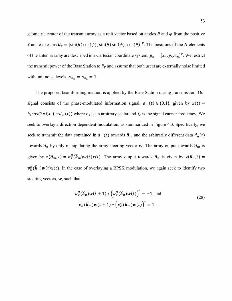
53
geometric center of the transmit array as a unit vector based on angles 𝜃 and 𝜙 from the positive
�̂� and �̂� axes, as �̂�𝒓 = [sin(𝜃) cos(𝜙) , sin(𝜃) sin(𝜙) , cos(𝜃)]𝑇. The positions of the 𝑁 elements
of the antenna array are described in a Cartesian coordinate system, 𝒑𝒏 = [𝑥𝑛, 𝑦𝑛, 𝑧𝑛]𝑇. We restrict
the transmit power of the Base Station to 𝑃𝑇 and assume that both users are externally noise limited
with unit noise levels, 𝜎�̂�𝒎 = 𝜎�̂�𝒏 = 1.
The proposed beamforming method is applied by the Base Station during transmission. Our
signal consists of the phase-modulated information signal, 𝑑𝑚(𝑡) ∈ {0,1}, given by 𝑥(𝑡) =
𝑏𝑠𝑐𝑜𝑠(2𝜋𝑓𝑐𝑡 + 𝜋𝑑𝑚(𝑡)) where 𝑏𝑠 is an arbitrary scalar and 𝑓𝑐 is the signal carrier frequency. We
seek to overlay a direction-dependent modulation, as summarized in Figure 4.3. Specifically, we
seek to transmit the data contained in 𝑑𝑚(𝑡) towards �̂�𝑚 and the arbitrarily different data 𝑑𝑛(𝑡)
towards �̂�𝑛 by only manipulating the array steering vector 𝒘. The array output towards �̂�𝑚 is
given by 𝒛(�̂�𝑚, 𝑡) = 𝒗𝑘𝐻(�̂�𝑚)𝒘(𝑡)𝑥(𝑡). The array output towards �̂�𝑛 is given by 𝒛(�̂�𝑛, 𝑡) =
𝒗𝑘𝐻(�̂�𝑛)𝒘(𝑡)𝑥(𝑡). In the case of overlaying a BPSK modulation, we again seek to identify two
steering vectors, 𝒘, such that
𝒗𝑘𝐻(�̂�𝑛)𝒘(𝑡 + 1) ∗ (𝒗𝑘
𝐻(�̂�𝑛)𝒘(𝑡))∗
= −1, and
𝒗𝑘𝐻(�̂�𝑚)𝒘(𝑡 + 1) ∗ (𝒗𝑘
𝐻(�̂�𝑚)𝒘(𝑡))∗
= 1 .
(28)

54
Figure 4.3: Graphical representation of the signal model for implementation of directional
modulation in the two-user scenario. The information, 𝑑𝑚, is phase-modulated and encoded onto
a carrier signal and transmitted by the array. The array steering vector is time-varied per the
exclusive disjunction between the information 𝑑𝑚 and the information 𝑑𝑛. Given the known array
manifold in the directions �̂�𝒎 and �̂�𝒏, and the appropriately designed steering vectors 𝒘𝟎𝑯 and 𝒘𝟏
𝑯,
the information signal decoded in the direction �̂�𝒎 yields 𝑑𝑚, and the information signal decoded
in the direction �̂�𝒏 yields 𝑑𝑛.
If we allow for some implementation loss denoted 휀, the modulation requirements in (28) can
be written as the convex subset Ψ, given (12). Further applying the practical constraint of not
requiring any active gain in the array, we can solve this problem using the constrained optimization
given by (13). We assume a simple, static line of sight channel model with no diffraction,
dispersion, or multipath between the transmitter and the receivers during the time scales of interest.
As such, we assume that the transmitter does not have access to any channel state information
(CSI), which would manifest here as a bulk rotation and scale of the constellation for each receiver.
Here, we assume that the receiver and eavesdropper are independently and correctly synchronized
by estimating their respective channel transfer functions by measuring the orientation of their
respective received constellations.
55
4.1.2 Secrecy Capacity
Using the antenna array, we seek to transmit different, confidential messages to multiple
receivers that occupy the same time-frequency subspace. Further, we seek to maximize the sum-
rate channel capacity between the broadcast transmitter and all the receivers with enhanced
physical layer security of confidential messages. In order to assess the effectiveness of this
technique in providing PHY-layer security, we consider the secrecy capacity defined as [74]
𝐶𝒔 = {𝐶�̂�𝒎 − 𝐶�̂�𝒏 ,
0, 𝛾�̂�𝒎 > 𝛾�̂�𝒏𝛾�̂�𝒎 ≤ 𝛾�̂�𝒏
, (29)
where 𝛾�̂�𝒎 and 𝐶�̂�𝒎 are the SNR and the channel capacity of User 0 in the direction �̂�𝑚,
respectively, and 𝛾�̂�𝒏 and 𝐶�̂�𝒏 are the SNR and the channel capacity of User 1 in the direction �̂�𝑛,
respectively. We define the overall transmitted SNR in the direction �̂� as �̅��̂� = 𝑃𝑇/𝜎2. We define
the overall received SNR as �̇��̂� = 𝑃𝑇 ||𝑯�̂�||2
/𝜎2, where 𝑯�̂� is the complex channel in the direction
�̂�. Finally, we define 𝛾�̂� as the final received SNR considered for use in computation of the channel
capacity.
The SNRs for typical intended and unintended users for the signal 𝑑𝑚(𝑡) are given by
𝛾𝑡𝑦𝑝𝑖𝑐 𝑙,�̂�𝒎 =𝑃𝑇𝜎𝑚2||𝑯�̂�𝒎||
𝟐
= �̇��̂�𝒎 , and
𝛾𝑡𝑦𝑝𝑖𝑐 𝑙,�̂�𝒏 =𝑃𝑇𝜎𝑛2||𝑯�̂�𝒏||
𝟐
(30)

56
Assuming that User 0 and User 1 have equivalent system noise and their wireless channel transfer
functions have equal norms, there is no secrecy capacity in this system. Any secrecy capacity
would be due to additional gain in the direction �̂�𝒎 as compared to the direction �̂�𝒏.
First, we compare this to a MIMO technique for establishing physical layer secrecy for a single
transmitter-receiver pair called the Artificial Noise method or the Null-Space method proposed by
Yang et al [5]. The Artificial Noise method or the Null-Space method diverts some fraction 𝛼 ∈
[0,1] of the signal transmit power 𝑃𝑇 to generating a second signal, typically only carrying noise,
exclusively in the direction �̂�𝒏, away from the intended user. This has the desired effect of reducing
the SINR in the direction of the unintended user (User 1); however, the natural extension of this
technique to transmit multiple signals requires halving the transmit time, thus halving the overall
capacity of the system. The Artificial Noise method or Null-Space method has been shown to
marginally outperform Time-division multiplexing (TDM) [5]. The SNRs for intended and
unintended users for the signal 𝑑𝑚(𝑡) using this method are given by
𝛾𝐴𝑟𝑡𝑖𝑓𝑖𝑐𝑖 𝑙 𝑁𝑜𝑖𝑠𝑒,�̂�𝒎 = 𝛼𝑃𝑇𝜎𝑚2||𝑯�̂�𝒎||
𝟐
= 𝛼�̇��̂�𝒎 , and
𝛾𝐴𝑟𝑡𝑖𝑓𝑖𝑐𝑖 𝑙 𝑁𝑜𝑖𝑠𝑒,�̂�𝒏 =𝛼𝑃𝑇 ||𝑯�̂�𝒏𝒘𝑰𝑺||
𝟐
1 − 𝛼𝑁 − 1𝑃𝑇 ||𝑯�̂�𝒏𝑾𝑨𝑵||
𝟐
+ 𝜎𝑛2.
(31)
By contrast, the proposed beamforming method for directional modulation coherently
overlays a modulation and interfering signal over the original information-bearing signal, causing
the SNR in the direction of the unintended user (User 1) to be dramatically reduced. For the
proposed beamforming method, the SNRs for User 0 in the direction �̂�𝒎 and User 1 in the direction
�̂�𝒏 are given by

57
𝛾�̂�𝒎 =𝑃𝑇𝜎𝑚2||𝑯�̂�𝒎||
𝟐
= �̇��̂�𝒎 , and
𝛾�̂�𝒏 =1
2(𝑃𝑇𝜎𝑛2||�̅��̂�𝒏||
𝟐
+𝑃𝑇 ||�̅��̂�𝒏||
𝟐
2𝑃𝑇 ||�̅��̂�𝒏||𝟐
+ 𝜎𝑛2).
(32)
The secrecy capacities for typical broadcast, Artificial Noise, and the proposed methods as a
function of the SNR of the signal intended for User 0 received by User 0, �̇� �̂� , are compared in
Figure 4.4. The secrecy capacities for a typical system and a system using the proposed
beamforming method for directional modulation assume a two-element array spaced by 0.75𝜆
where the users are spaced by 40° about the boresight of the Base Station transmit array.
Performance calculations for the Artificial Noise (Null-Space) method assumes a three-element
array, as in [5]. The proposed beamforming method for directional modulation easily outperforms
calculated performance for both the typical system and the system using the Artificial Noise
method due to the fact that the original signal is modulated into an interferer at the PHY-layer in
the direction �̂�𝒏.

58
Figure 4.4: Comparison of the secrecy capacities for typical broadcast, Artificial Noise, and the
proposed methods as a function of the SNR of the signal intended for User 0 received by User 0,
�̇� �̂� . Performance calculations for the secrecy capacities for a typical system and a system using
the proposed beamforming method for directional modulation assume a two-element array spaced
by 0.75λ where the users are spaced by 40° about the boresight of the Base Station transmit array,
whereas the performance calculations for the Artificial Noise (Null-Space) method assumes a
three-element array, as in [5]. The proposed beamforming method for directional modulation
easily outperforms calculated performance for both the typical system and the system using the
Artificial Noise method.
4.2 Increasing the Capacity of Confidential
Messages over Wireless Broadcast Channels
The proliferation of embedded devices attached to networks, commonly referred to as the
Internet-of-Things (IoT), has driven wireless communications into commercial, military,

59
industrial, and personal devices, estimated to number in excess of 6 billion devices in 2016 and
projected to exceed 20 billion devices by 2020 [75]. Given these staggering numbers, limited
spatial and spectral resources, and the broadcast nature of wireless communications systems, it is
unreasonable to expect privacy and security to be inherent in these device networks. Further,
information and commands carried over these broadcast channels to IoT devices require security
and privacy as they expand to include medical devices (both diagnostic and treatment), vehicles,
and industrial control systems, just to name a few.
Despite the misleading description of wireless point-to-point links, we must consider the
communications to and from such IoT devices to be broadcast channels; that is, when transmitting,
anticipate both legitimate, intended receivers and illegitimate, unintended receivers, called
eavesdroppers; reciprocally, when receiving, anticipate a multiple access environment, including
both interference and intentional spoofing. Finally, we must enable IoT devices to effectively
access broadcast channels while maintaining typically small size, light weight, and minimized
power consumption.
For the single-user channel, Shannon famously described the information-theoretic channel
capacity bound based on signal and noise entropies [76]. This work was extended to single-user
MIMO systems [77] and broadcast channels [78]. Several bounds have been established for MIMO
broadcast channels, providing a theoretical maximum achievable sum-rate channel capacity [17],
[79], [80]. A technique dubbed “Dirty Paper Coding” was introduced by Costa [72] and later
shown to achieve the Sato upper bound for MIMO broadcast channels [17] in the two-user case
[73]. Further study has corroborated these claims from an information theoretic standpoint [81]–

60
[84], and extended the claims to provide bounds for the secrecy capacity of MIMO broadcast
channels [85], [86].
The Dirty Paper Coding technique [72] is similar to the Artificial Noise method (Null-Space
method), but is designed to accommodate multiple, independent, and legitimate information-
bearing signals intended for multiple users. Dirty Paper Coding simultaneously transmits the two
information-bearing signals, which reduces the SINR of each signal considerably at both users. To
combat this loss of SINR, Dirty Paper Coding transmits a coded signal, 𝒘𝑫𝑷𝑪 = 𝑾𝑫𝑷𝑪𝒖, using a
precoding matrix, 𝑾𝑫𝑷𝑪 ∈ ℂ𝑁×𝑆, where 𝑁 is the number of transmit antenna elements and 𝑆 is the
number of receivers considered. The 𝑆×1 codebook vector, 𝒖, is constrained such that 𝐸[𝒖𝒖𝐻] =
𝑰𝑅. The transmitted signal is constrained by the total output power such that 𝑇𝑟(𝒙𝒙𝐻) ≤ 𝑃𝑡. The
SINR of the information 𝑑𝑚 at the primary intended receiver using dirty paper coding (𝛾𝑚, ̂ 𝐷𝑃𝐶 ) is
given by
𝛾𝑚, ̂ 𝐷𝑃𝐶 = 𝛼 ||𝒗𝒌
𝑯(�̂�𝑚)𝒘𝑫𝑷𝑪||2
𝑃𝑇 = 𝛼 ||𝑯�̂� ||2
𝑃𝑇, (33)
for 𝜎𝑚 = 𝜎𝑛 = 1, given knowledge of the wireless channel transfer function 𝑯�̂� and noncausal
knowledge of the other signals transmitted in the codebook vector, 𝒖. The parameter 𝛼 ∈ [0,1] is
a tunable parameter indicating the ratio of the transmitted power allocated to 𝑑𝑚 and the total
transmitted power 𝑃𝑇 for the two-user scenario. The SINR of 𝑑𝑛 at the same receiver is designed
to be
𝛾𝑛, ̂ 𝐷𝑃𝐶 =
(1 − 𝛼) ||𝑯�̂�𝑚||2𝑃𝑇
𝛼 ||𝑯�̂�𝑚||2𝑃𝑇 + 1
; (34)
61
however, since this receiver has noncausal knowledge of 𝑑𝑛, the interference caused by 𝑑𝑛 is
subtracted from the received signal. It should be noted that this scheme limits the utility of Dirty
Paper Coding from a secrecy capacity standpoint, since one receiver requires non-causal
knowledge of all the information-bearing signals.
The second user receives an interference-corrupted version of their signal, observing the first
receiver’s signal as interference, but without knowledge of 𝑑𝑚. The SINR of 𝑑𝑚 at the unintended
receiver using dirty paper coding (𝛾𝑚, ̂ 𝐷𝑃𝐶 ) is given by
𝛾𝑚, ̂ 𝐷𝑃𝐶 =
𝛼 ||𝑯�̂� ||2
𝑃𝑇
(1 − 𝛼) ||𝑯�̂� ||2
𝑃𝑇 + 1, (35)
and the SINR of 𝑑𝑛 at the same receiver is given by
𝛾𝑛, ̂ 𝐷𝑃𝐶 =
(1 − 𝛼) ||𝑯�̂� ||2
𝑃𝑇
𝛼 ||𝑯�̂� ||2
𝑃𝑇 + 1. (36)
It has been shown that Dirty Paper Coding achieves the Sato Bound for MIMO broadcast channel
capacity [73], [82]; however, the ovarall secrecy capacity is limited by 𝛼 and 𝛾𝑚, ̂ 𝐷𝑃𝐶 .
We propose a novel coding technique implemented by the proposed beamforming method,
first introduced in [67], and show that it can outperform the Dirty Paper Coding technique both in
terms of sum rate capacity and secrecy capacity. We achieve this by using time-varying array
steering vectors, violating the implicit assumption of available degrees of freedom supporting the
proof of optimality of Dirty Paper Coding and its variants [73]. Further, rather than considering
multiple users as interference channels [73], the proposed method implements a direction-

62
dependent overlay modulation, which controls co-channel interference generated by the
transmitter in the direction of other users and thus greatly increases the achievable signal-to-
interference-plus-noise ratio (SINR) in each channel. We also show that the proposed
beamforming method can exceed the Sato Bound [17], which implicitly assumes no time-varying
control over the wireless channel transfer function; however, the channel capacity using the
proposed method remains well within the Shannon capacity limits. Since the proposed method
implements an overlay modulation by time-varying the array steering vector, the Sato Bound [17]
does not expressly apply to the proposed method; however the Sato Bound is currently accepted
as the current state-of-the-art for sum-rate capacity in a wireless broadcast channel [73].
In further contrast to the Dirty Paper Coding method, the proposed directional modulation
method is an overlay modulation scheme that seeks to simultaneously minimize the SINR of both
signals at their respective unintended receivers, thereby increasing the achievable sum rate
capacity and secrecy capacity. The SINR of 𝑑𝑚 at the intended receiver using the proposed
method is given by
𝛾𝑚, ̂ 𝐷𝑀 = ||𝒗𝑘
𝐻(�̂�𝑚)(𝒘𝟎 +𝒘𝟏)||2 𝑃𝑇2
(37)
and the SINR of 𝑑𝑛 at the intended receiver is given by
𝛾𝑛, ̂ 𝐷𝑀 = ||𝒗𝑘
𝐻(�̂�𝑛)(𝒘𝟎 +𝒘𝟏)||2 𝑃𝑇2. (38)
The interference terms are negligible, that is 𝛾𝑛, ̂ 𝐷𝑀 0 and 𝛾𝑚, ̂
𝐷𝑀 0 if 휀 is chosen to be
sufficiently small.

63
4.3 Secrecy Capacity in a Broadcast Channel
To the best of our knowledge, determining the capacity region and upper bound for the non-
degraded MIMO broadcast channel is still an open problem. Several information theoretic bounds
have been established [17], [79], [80] and used to prove the optimality of different coding
techniques [73], [81]–[87]. Principally, the Dirty Paper Coding technique [72] was shown to be an
optimal coding technique by achieving the Sato upper bound for MIMO broadcast channels in the
two-user scenario [73].
We note here that the Sato bound is based on information theory, and does not account for the
ability to time-vary the broadcast wireless channel transfer function by electrically steering the
antenna array. In doing so, we take advantage of an additional degree of freedom, enabling us to
transmit multiple messages simultaneously with sufficient efficiency to outperform the Dirty Paper
Coding technique, which has been shown to be tight to the Sato bound in the two-user case. In
fact, system models for MIMO and standard broadcast channel bounds may include, but do not
take advantage of the direction-dependent and deterministic channel inherent to locally time-
invariant, narrowband, line-of-sight, and minimal multipath assumptions, which are typical in
array signal processing [1]. For example, in using information theoretic approaches to determining
channel capacities, several references treat the MIMO channel purely as a realization of a random
variable due to the possibility of significant and unpredictable multipath [17], [77], [73], [82], [83],
[85], [87], [88], also called a Rayleigh fading channel. Here, we exploit the known array manifold
embedded in the wireless channel transfer function matrix and show that the proposed method can

64
exceed the performance of Dirty Paper Coding, which achieves the Sato upper bound for MIMO
broadcast channels. Numerical comparisons of these coding techniques are shown in Chapter 5.
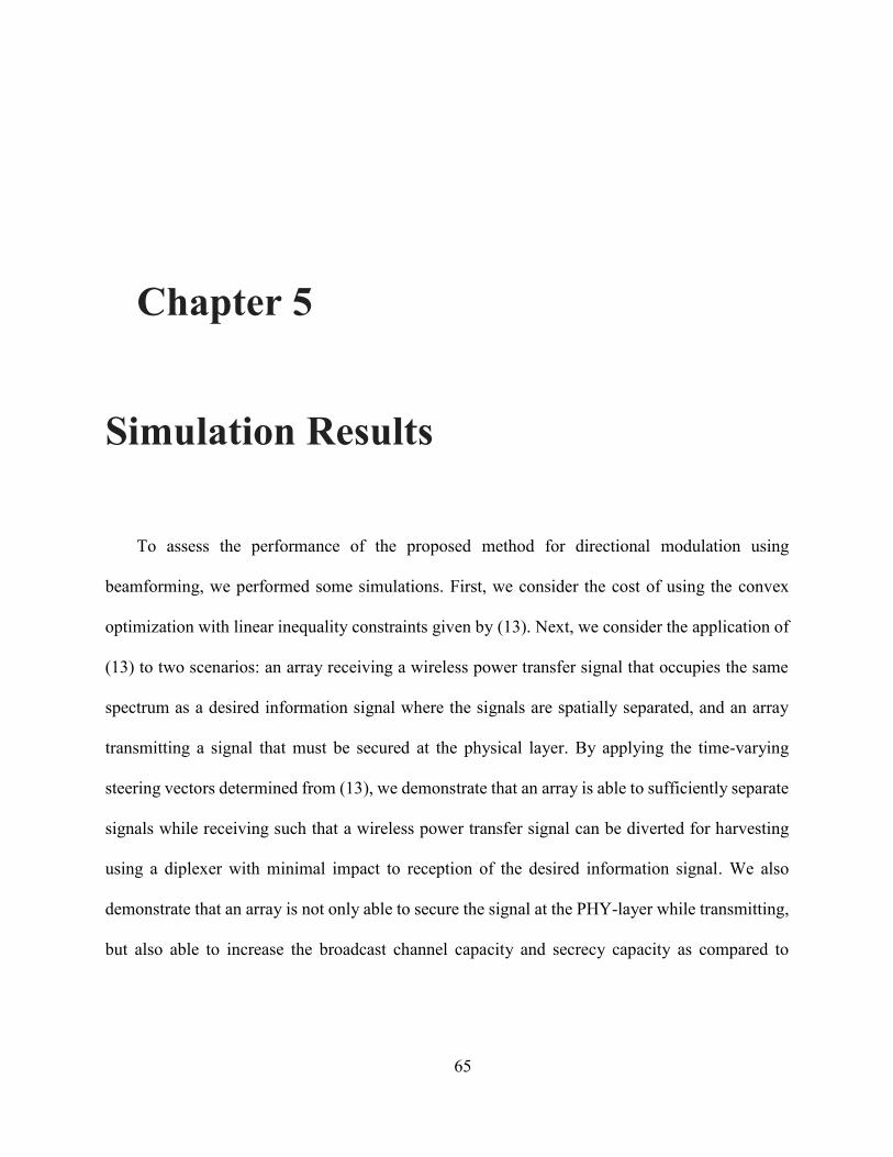
65
Simulation Results
To assess the performance of the proposed method for directional modulation using
beamforming, we performed some simulations. First, we consider the cost of using the convex
optimization with linear inequality constraints given by (13). Next, we consider the application of
(13) to two scenarios: an array receiving a wireless power transfer signal that occupies the same
spectrum as a desired information signal where the signals are spatially separated, and an array
transmitting a signal that must be secured at the physical layer. By applying the time-varying
steering vectors determined from (13), we demonstrate that an array is able to sufficiently separate
signals while receiving such that a wireless power transfer signal can be diverted for harvesting
using a diplexer with minimal impact to reception of the desired information signal. We also
demonstrate that an array is not only able to secure the signal at the PHY-layer while transmitting,
but also able to increase the broadcast channel capacity and secrecy capacity as compared to
Chapter 5
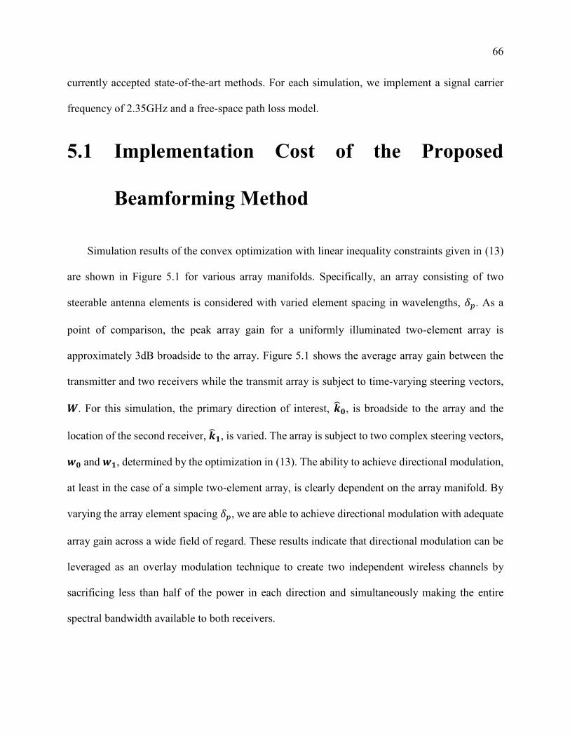
66
currently accepted state-of-the-art methods. For each simulation, we implement a signal carrier
frequency of 2.35GHz and a free-space path loss model.
5.1 Implementation Cost of the Proposed
Beamforming Method
Simulation results of the convex optimization with linear inequality constraints given in (13)
are shown in Figure 5.1 for various array manifolds. Specifically, an array consisting of two
steerable antenna elements is considered with varied element spacing in wavelengths, 𝛿𝑝. As a
point of comparison, the peak array gain for a uniformly illuminated two-element array is
approximately 3dB broadside to the array. Figure 5.1 shows the average array gain between the
transmitter and two receivers while the transmit array is subject to time-varying steering vectors,
𝑾. For this simulation, the primary direction of interest, �̂�𝟎, is broadside to the array and the
location of the second receiver, �̂�𝟏, is varied. The array is subject to two complex steering vectors,
𝒘𝟎 and 𝒘𝟏, determined by the optimization in (13). The ability to achieve directional modulation,
at least in the case of a simple two-element array, is clearly dependent on the array manifold. By
varying the array element spacing 𝛿𝑝, we are able to achieve directional modulation with adequate
array gain across a wide field of regard. These results indicate that directional modulation can be
leveraged as an overlay modulation technique to create two independent wireless channels by
sacrificing less than half of the power in each direction and simultaneously making the entire
spectral bandwidth available to both receivers.

67
Figure 5.1: Curves of average loss in array gain in dB vs the direction of the second receiver in
degrees from broadside for a two-element array with spacing 𝛿𝑝. In this simulation, the array
implements steering vectors resulting from the convex optimization in (13). Here, one receiver is
located broadside to the array and the abscissa denotes the direction of the second receiver in
degrees from broadside to the array. These results indicate that two independent messages can be
sent in different directions more efficiently than by merely equally dividing the available power or
bandwidth between the receivers.
We repeat this simulation for the directions of the two receivers, �̂�𝟎 and �̂�𝟏, equally spaced
from broadside to the array. Curves in Figure 5.2 show the average array gain between the
transmitter and two receivers while the transmit array is subject to the time-varying steering
vectors, 𝑾, for varied element spacing 𝛿𝑝 in wavelengths. For this simulation, the broadside of the
array is aimed directly between the two receivers, and the spacing between the receivers is varied.
As a point of comparison, the peak array gain for a uniformly illuminated two-element array is

68
approximately 3dB. We demonstrate the ability to achieve directional modulation with adequate
array gain across a wide field of regard by varying the array element spacing 𝛿𝑝.
Figure 5.2: Curves of average loss in array gain in dB vs the separation of two receivers in degrees
for a two-element array with spacing 𝛿𝑝. In this simulation, the receivers are equally spaced from
broadside to the array and the abscissa denotes spacing between the two receivers. The average
loss in array gain is referenced to the ideal array gain of a two-element array at broadside. This
plot indicates that two independent messages can be sent in different directions more efficiently
than by merely equally dividing the available power or bandwidth between the receivers.

69
5.2 Simultaneous Wireless Information and
Power Transfer
In this Section, we present simulation results indicating that the proposed method for
directional modulation using beamforming can be used to effectively separate co-channel signals,
even using an array with only two elements. In this simulation, a continuous wireless power
transfer signal is centered on the same frequency with the same bandwidth as an information-
bearing signal, but the signals are spatially separated. By properly overlaying Binary Offset Carrier
(BOC) modulation only onto the wireless power transfer signal using the proposed beamforming
method, it is sufficiently separated in frequency from the information-bearing signal. With
sufficient frequency separation between the information-bearing signal and the wireless power
transfer signal, the latter can be diverted for harvesting using a passive device, such as a diplexer,
with minimal impact to reception and bit error rate of the information-bearing signal.
We simulate a simple two-element array with an inter-element spacing of 0.75 wavelengths
attempting to separate an information-bearing signal from a wireless power transfer signal. Both
signals arbitrarily occupy 20MHz of half-power bandwidth at 2.35GHz center frequency. We
apply directional modulation using the proposed method to separate the signals. Despite the time-
varying nature of the array steering vector, no discernable modulation or distortion and a minimal
increase in bit error rate was observed on the information-bearing signal in the intended direction.
Meanwhile, a variety of modulations, including direct sequence spread spectrum and binary offset

70
carrier, were applied to and observed on the wireless power transfer signal in the unintended
direction.
5.2.1 Direct Sequence Spread Spectrum Modulation
Overlay
The power spectrum of the unmodulated, undistorted information-bearing signal is shown in
Figure 5.3 with a classical BPSK modulation spectrum with 20𝑀𝐻𝑧 of bandwidth. We compare
it to the power spectrum when the information-bearing signal is overlaid with a pseudorandom
spreading sequence with a spreading factor of 20. Clearly, we observe the peak power spectral
density of the information-bearing signal at the center frequency approximately 20 times greater
than the average power spectral density of the direct sequence spread spectrum modulated wireless
power transfer signal. While we observe greater than an order of magnitude of suppression within
the information bandwidth, we seek to achieve better suppression as explained next.

71
Figure 5.3: Simulation results showing a comparison of the spectrum of a BPSK-modulated signal
with the spectrum when direct sequence spread spectrum modulation is overlaid onto the signal
using directional modulation, applied by the proposed beamforming method. All of the signals
used in these simulations are normalized to the same net power for meaningful comparison of
power distribution.We assess the performance of the proposed method over a variety of spreading
factors, each during a number of Monte Carlo trials. As expected with direct sequence spread
spectrum modulation, larger spreading factors provide better suppression performance.
Performance here is measured as the amount of wireless power transfer energy within the
information bandwidth that has been shifted out of band. The results for direct sequence spread
spectrum modulation are shown in Figure 5.4, indicating that close to 99% of the wireless power
transfer signal energy can be spread out of band using a direct sequence spread spectrum overlay
with a spreading factor of 100. We note that this would require updating the array steering vector
100 times faster than the information symbol rate, which would impose restrictions on the array
hardware. We next show a technique to achieve similar suppression performance with a
significantly reduced spreading factor.

72
Figure 5.4: Simulation results of direct sequence spread spectrum modulation overlaid onto a
BPSK-modulated wireless power transfer signal using directional modulation. These results show
the relative amount of energy within the information bandwidth (“in-band”) decreasing and
spreading outside the information bandwidth (“out-of-band”) based on the spreading factor used,
which is defined as the ratio of the spread bandwidth to the information bandwidth.
5.2.2 Binary Offset Carrier Modulation Overlay
To achieve better suppression within the information bandwidth and spectrum shifting
performance, binary offset carrier modulation was overlaid onto the wireless power transfer signal.
The average power spectrum from a number of Monte Carlo trials while using a binary offset
carrier with a spreading factor of 5 (BOC(10,2)) is shown in Figure 5.5. The original and
undistorted BPSK-modulated signal is at the center frequency showing the information-bearing
bandwidth while the BOC(10,2)-modulated wireless power transfer signal is shown with
significantly reduced peak power spectral density at the carrier frequency and within the

73
information bandwidth. A bulk of the signal energy has shifted in spectrum by more than 5 times
the information bandwidth.
Figure 5.5: Simulation results showing a comparison of the power spectrum of a BPSK-modulated
signal with the spectrum when binary offset carrier (BOC) modulation is overlaid onto the signal
using directional modulation applied by the proposed beamforming method. In this example, both
signals are centered at the same frequency, 2350𝑀𝐻𝑧.
As observed in Figure 5.6, binary offset carrier modulation shows considerably more
favorable results, removing the same 99% of wireless power transfer signal energy out of band as
direct sequence spread spectrum modulation, with only a spreading factor of 10. Overlaying
BOC(10,2) modulation using the proposed technique would require significantly less complex
array hardware since the array steering vectors would need to be updated an order of magnitude
less frequently for the same performance. Simulation results show that binary offset carrier
modulation with a spreading factor of 100 can achieve greater than 40dB reduction of wireless
74
power transfer energy within the information bandwidth by shifting the energy out of band, to
where it can be harvested using conventional circuitry.
Figure 5.6: Simulation results of direct binary offset carrier modulation overlaid onto a BPSK-
modulated wireless power transfer signal using directional modulation. These results show the
relative amount of energy within the information bandwidth (“in-band”) decreasing and spreading
outside the information bandwidth (“out-of-band”) based on the spreading factor used, which is
defined as the ratio of the spread bandwidth to the information bandwidth.
5.3 Disguising Transmissions for Physical Layer
Secrecy
In this Section, we provide simulation results indicating that directional modulation using only
the proposed passive beamforming method can provide additional physical layer security by
modulating the information-bearing signal into a valid, spoofed signal only in the direction of the
eavesdropper. Not only does this method of selectively overlaying modulation reduce the SNR of
the information-bearing signal in the direction of the eavesdropper, but it even moreso reduces the

75
SINR of information-bearing signal by replacing it with an arbitrarily different signal. Throughout
this section, the transmitter considered is an array of 2 elements spaced 0.75 wavelengths apart.
The intended receiver is located broadside to the transmitter array in the direction �̂�𝒎, and the
eavesdropper is located 30° from broadside to the transmitter array in the direction �̂�𝒏.
A randomly generated binary information sequence denoted by 𝑑𝑚(𝑡) is modulated and
routed to each array element, reproduced in Figure 5.7. Then, the array steering vector 𝒘(𝑡) is
determined from (13) and modulated according to the exclusive disjunction of the genuine binary
information sequence and the spoofed binary information sequence, 𝑑𝑛(𝑡), given by 𝑑𝑚(𝑡) ⊕
𝑑𝑛(𝑡). The bit error rates are recorded at the receiver in the direction �̂�𝒎 and at the eavesdropper
in the direction �̂�𝒏 for a variety of bit energy to noise ratios, using 𝑑𝑚(𝑡) as the signal template
for the receiver, and 𝑑𝑛(𝑡) as the signal template for the eavesdropper. Otherwise static channel
coefficients were assumed for this simulation, and a line of sight channel model free of multipath
and dispersion is used.
76
Figure 5.7: Schematic diagram showing a genuine binary information sequence, 𝑑𝑚 being sent to
the beamformer which is modulated according the exclusive disjunction of 𝑑𝑚 and 𝑑𝑛. This results
in the genuine information sequence, 𝑑𝑚, being transmitted in the direction �̂�𝑚, and the spoofed
information sequence, 𝑑𝑛, being transmitted in the direction �̂�𝑛. This directional modulation
technique provides physical layer security since the genuine information sequence, 𝑑𝑚, becomes
unrecoverable in the direction �̂�𝑛.
The simulated bit error rates are recorded at the receiver in the direction �̂�𝒎 and at the
eavesdropper in the direction �̂�𝒏 for a variety of bit energy to noise ratios are shown in Figure 5.8.
The performance of the array using the proposed beamforming method for directional modulation
is compared to the theoretical performance of an otherwise identical single element transmitter,
and an otherwise identical, ideal two-element array transmitter without time-varying
beamforming. The performance results indicate that bit error rate achievable using the propsed
method is higher than for an ideal array steered towards one of the receivers; however, the bit error
rate achievable by directional modulation outperforms the single element transmitter. It should be
noted that the ideal two element array must be steered towards only one of the receivers, and must
time division multiplex to address both receivers independently, which provides no additional
physical layer security. Using the proposed method, we achieve low bit error rates for the
respective, independent information signals in both the direcrtion of the recevier and the

77
eavesdropper. We should also note that the bit error rate performance achieved is highly dependent
of the array manifold for this geometry, as shown in Figure 5.1 and Figure 5.2. These results
indicate that an array transmitter can establish secrecy for a transmitted signal at the physical layer
using only beamforming by spoofing eavesdroppers and sacrificing less than half of the ideal array
gain in the both directions.
Figure 5.8: Simulation of bit error rates for BPSK modulation applied using directional modulation
in the directions �̂�𝒎 and �̂�𝒏 compared to bit error rates for single-channel BPSK without
beamforming.The data sent in the direction �̂�𝒏 is independent of the data sent in the direction �̂�𝒎,
and only modulated by beamforming.
For these simulations, randomly generated binary information sequences intended for both the
receiver and eavesdropper were used for these simulations to show that the signal received by the
eavesdropper can be independently and arbitrarily manipulated from the original signal. We
recognize that depending on the signal parameters and concept of operations, the spoofed signal
may closely resemble the genuine signal.

78
5.4 Increasing the Capacity of Confidential
Messages over Wireless Broadcast Channels
We executed several simulations to assess the sum-rate capacity and secrecy capacity
performance of the proposed beamforming method for directional modulation. First, we compute
the achievable capacity region for a two-user directional modulation scenario using the system
model reproduced in Figure 5.9 and the proposed beamforming method. We compare this
performance to theoretical bounds and the current state-of-the-art coding approaches for MIMO
broadcast channels assuming narrowband, static, direct line-of-sight channels. Next, we compare
the achievable multi-user secrecy capacity of directional modulation to these same published
techniques. For all simulations, the time-varying steering vectors for directional modulation are
determined from the optimization in (13) and implemented as shown in Figure 5.10.

79
Figure 5.9: Graphical representation of the signal model for implementation of directional
modulation in the two-user scenario. The information, 𝑑𝑚, is phase-modulated and encoded onto
a carrier signal and transmitted by the array. The array steering vector is time-varied per the
exclusive disjunction between the information 𝑑𝑚 and the information 𝑑𝑛. Given the known array
manifold in the directions �̂�𝒎 and �̂�𝒏, and the appropriately designed steering vectors 𝒘𝟎𝑯 and 𝒘𝟏
𝑯,
the information signal decoded in the direction �̂�𝒎 yields 𝑑𝑚, and the information signal decoded
in the direction �̂�𝒏 yields 𝑑𝑛.
Figure 5.10: Schematic diagram showing two genuine binary information sequences, 𝑑𝑚 and 𝑑𝑛
being transmitted in the directions �̂�𝑚 and �̂�𝑛, respectively. The beamformer time-varies the array
steering vector per the exclusive disjunction of 𝑑𝑚 and 𝑑𝑛. This directional modulation technique
enables the simultaneous transmission of 𝑑𝑚 and 𝑑𝑛 with high sum-rate capacity.

80
For the purposes of this simulation, we assume that each receiver separately calibrates the
symbol decision threshold for the received constellation based on the first few received symbols,
as typically done in practice with known pilot sequences. The signal-to-noise ratio (SNR) is
measured from the simulated received symbols, and the mean SNR of all symbols to each receiver
is reported. The achievable performance of the transmit array using the proposed beamforming
method is highly dependent on the array manifold, which includes the array element spacing δp,
the spatial separation of the receivers in question Δθ, and the implementation loss parameter ε. We
exercised and explored these parameters through each of the simulations presented.
Considering the terminology outlined in Figure 5.11, we identify two receivers, User 0 and
User 1, each the legitimate, intended recipient of a confidential message. Both receivers are
susceptible to interference from the other confidential message, and capable of eavesdropping on
the other confidential message. In order to assess the effectiveness of the proposed beamforming
method for broadcasting confidential messages, we consider the secrecy capacity introduced by
Barros [74], and slightly modified here as
𝐶𝑚 = {𝐶𝑚,�̂�𝒎 − 𝐶𝑚,�̂�𝒏 ,
0, 𝛾𝑚,�̂�𝒎 > 𝛾𝑚,�̂�𝒏𝛾𝑚,�̂�𝒎 ≤ 𝛾𝑚,�̂�𝒏
, (39)
where 𝐶𝑚 is the secrecy capacity of the message 𝑑𝑚(𝑡), 𝐶𝒎,�̂�𝒎 is the acheivable channel
capacity per unit bandwidth of the intended recipient of 𝑑𝑚(𝑡) in the direction �̂�𝒎 given by
𝐶𝑚,�̂�𝒎 = log2(1 + 𝛾𝑚,�̂�𝒎), 𝛾𝒎,�̂�𝒎 is the SINR of 𝑑𝑚(𝑡) at the intended recipient of 𝑑𝑚(𝑡), 𝐶𝑚,�̂�𝒏
is the acheivable channel capacity per unit bandwidth of the unintended recipient of 𝑑𝑚(𝑡) in the
direction �̂�𝒏 specific to the signal 𝑑𝑚(𝑡), and 𝛾𝑛,�̂�𝒎 is the SINR of 𝑑𝑚(𝑡) at the unintended

81
recipient. We can similarly compute the secrecy capacity for the second message, 𝑑𝑛(𝑡) as 𝐶𝑛.
The sum-rate secrecy capacity of the system is simply given as 𝐶𝑆 = 𝐶𝑚 + 𝐶𝑛.
Figure 5.11: Diagram of Base Station transmitter array servicing User 0 and User 1, which are
spatially separated with respect to the transmitter array. The Base Station possesses two messages:
𝑑𝑚 intended for User 0 and 𝑑𝑛 intended for User 1. Due to the broadcast nature of the Base Station
and expected wireless channels, we expect that both messages are perceptible by their respective
unintended receivers.
To maximize the sum-rate secrecy capacity of the system, we must simultaneously maximize
the SINR of each signal at the respective intended receiver while minimizing the SINR of each
signal at the respective unintended receiver. We have shown that directional modulation inherintly
provides this simultaneous maximizing and minimizing of SINRs in contrast to other MIMO
broadcast coding techniques. A typical array transmitter may use beamforming to focus a signal
onto an intended user and steer a null towards the direction of the unintended user, maximizing
the acheivable secrecy capacity for that particular signal; however, half of the secrecy capacity is
sacrificed to similarly transmit the second message. This simple trade-off, also refered to as Time-
Base
Station
…
User 0
Intended recipient of 𝒎Unintended recipient of 𝒏
1
N
�̂�𝒎
�̂�𝒏User 1
Unintended recipient of 𝒎Intended recipient of 𝒏

82
division multiplexing (TDM), establishes the lower achievable threshold for performance
comparison.
First, we compare the simulated broadcast performance of the proposed beamforming method
for directional modulation to the Dirty Paper Coding achievable rate region, due to the complexity
in computing the Sato upper bound for MIMO broadcast channels [17], since Dirty Paper Coding
achieves the Sato Bound for MIMO broadcast channel capacity [73], [82]. Using Dirty Paper
Coding, an achievable rate vector for the ith of 𝐾 users is given by [89]
𝑅𝜋(𝑖)𝐷𝑃𝐶 = 𝑙𝑜𝑔 (
|𝑰𝑵 +𝑯𝝅(𝒊)(∑ 𝜮𝝅(𝒋)𝒋≥𝒊 )𝑯𝝅(𝒊)𝑯 |
|𝑰𝑵 +𝑯𝝅(𝒊)(∑ 𝜮𝝅(𝒋)𝒋>𝒊 )𝑯𝝅(𝒊)𝑯 |
) , 𝑓𝑜𝑟 𝑖 = 1,… , 𝐾, (40)
for any positive semidefinite covariance matrices satisfying 𝑇𝑟(Σ1, … , Σ𝐾) < 𝑃𝑇 and MIMO
channel matrix 𝑯, where 𝑰𝑁 is the identity matrix of size 𝑁. The achievable capacity region using
Dirty Paper Coding is the convex hull of the union of all achievable rate vectors given in (40).
Steering vector solutions for a two-element transmit array and two spatially separated users
are computed using the convex optimization in (13) for varying angular separation of users, Δθ.
Using the proposed beamforming method for directional modulation, an achievable rate vector for
the user in the direction �̂�𝒓 is given by
𝑅𝑟𝐷𝑀 =
𝟏
𝟐𝑙𝑜𝑔 ((1 +
𝜷𝒓,𝟎𝑷𝑻
𝜼𝒓) (1 +
𝜷𝒓,𝟏𝑷𝑻
𝜼𝒓)), (41)
where 𝛽𝑟,𝑠 is a measure of the loss from the maximum possible array gain, given by
𝛽𝑟,𝑠 = 1 − |𝒗𝒌𝐻(�̂�𝒓)𝒘𝑠|. (42)

83
The achievable rate vectors and, consequently, the broadcast channel capacity are dependent on
the array manifold, indicating that the proposed directional modulation technique may not
outperform other techniques for every given array and receiver geometry. Figure 5.2 shows the
average achievable loss of array gain 𝛽, for various array manifolds given that boresight of the
array is aimed in between two receivers. The proposed beamforming method for directional
modulation is generalized for arrays with an arbitrary number of elements and arbitrary receiver
locations. Of note is that an average array loss of 3𝑑𝐵 would have equivalent channel capacity
performance to the simple time-division multiplexing (TDM) scheme for two receivers.
The resulting, achievable broadcast channel rates for each user by using the proposed method
are shown in Figure 5.12 for various array element spacing, 𝛿𝑝, and spatial separation of the
receivers, Δ𝜃. The Dirty Paper Coding achievable rate region is computed as in (40) and shown in
Figure 5.12 for comparison against achievable rates for the proposed beamforming method. Of
note is that there are many array and receiver geometries where the achievable capacity using the
proposed method is beyond the achievable capacity of the Dirty Paper Coding scheme, which has
been considered an optimal coding scheme for non-time-varying channels [73]. We submit that
prior discussions have conflated time-varying wireless channel transfer functions, such as fading
channels treated as random variables, with time-varying spatial coding schemes, which we have
used here.

84
Figure 5.12: Maximum achievable broadcast channel capacities in bits/s/Hz for a two-element
array transmitting to two users. The element spacing in the array, 𝛿𝑝 in wavelengths, and the spatial
separation of the receivers is varied, showing the dependence of the sum-rate broadcast channel
capacity performance on the array manifold. The points shown are solutions to the optimization in
(13) and can exceed the Dirty Paper Coding (DPC) achievable rate region in a broadcast channel
given the proper system geometry. Here, the DPC achievable rate region is tight to the Sato upper
bound for MIMO broadcast channels.
The benefits of increased achievable sum-rate capacity due to the proposed beamforming
method for directional modulation are clear, and stem from the fact that the implementation of the
overlay modulation using time-varying array steering vectors produces minimal interference to
either User from message intended for the other User. For these simulation results, the efficiency

85
metric, 휀, used in the optimization in (13) is selected as 휀 = 0.05, which corresponds to a negligible
modulation error ratio of −26𝑑𝐵. Consequently, these achievable capacities have the added
benefit of being inherently confidential at the physical layer, leading to even greater performance
in secrecy capacity.
5.5 Robustness of the Proposed Method to Angle
and Frequency
We have demonstrated the dependence of the performance of the proposed beamforming
method on the array manifold. A practical consideration is the performance of the steering vectors
designed using (13) for a single frequency, a fixed element spacing, and for two receivers at fixed
locations when the operating frequency changes or the receivers’ locations are known only to finite
accuracy. While the steering vectors can be recomputed for changing center frequency, if the
directions towards both receivers is not precisely known or is slowly time-varying, constantly re-
computing the steering vectors becomes both impractical and ineffective. Further, in the case of
secrecy and physical layer security, it is useful to know the spatial extents to which the confidential
signals are recoverable by unknown eavesdroppers.
To this end, we simulate the system describe in Figure 5.11 using the signal model shown in
Figure 5.9. The optimization in (13) is used to compute the steering vectors for an array with two
elements spaced at 1.1𝜆, operating at a center frequency of 2.4𝐺𝐻𝑧. Here, User 0 is located
broadside to the two-element array, and User 1 is located 20° from broadside. Figure 5.13 shows
a greyscale image of the phase modulation achieved in degrees when the steering vectors are time-

86
varied, with the average array gain contour overlay. Of note is that the transition between regions
where modulation is applied and is not applied falls into either a peak or a null of the array gain
pattern. Further, we note that the precise location of both Users is not required since this particular
steering vector design allows for at least 15° of uncertainty in the direction of both Users at the
design frequency. Further, if the operating frequency is changed, the modulation regions hold
sufficiently stable over more than 2𝐺𝐻𝑧. Finally, we note that the modulation region for the User
located 20° from broadside is also observable 20° from broadside opposite the User. This can be
mitigated by designing a set of steering vectors that assumes 3 Users, one at +20° from broadside,
one at broadside, and one at −20° from broadside. The design and implementation method for
designing steering vectors with 3 Users is given in Figure 2.2 and (15).
Figure 5.13: Greyscale image indicating the direction-dependent phase modulation in degrees due
to time-varying the steering vector state for the array. Directional modulation is implemented using
a two-element array spaced by 1.1𝜆 at 2.4𝐺𝐻𝑧. Dotted lines show an example operating point at
2.4𝐺𝐻𝑧 with one User at broadside and the other at 20° from broadside. The contour indicates the
achieved array gain using the proposed method.

87
We repeat the simulation and use the optimization in (13) to compute the steering vectors for
an array with two elements spaced at 1.1𝜆, operating at a center frequency of 2.4𝐺𝐻𝑧. Here, we
have modified the location of User 0 and User 1, such that they are separated by 5° and are both
off-broadside. Figure 5.14 shows a greyscale image of the phase modulation achieved in degrees
when the steering vectors are time-varied, with the average array gain contour overlay. Of note
here is that the transition between regions where modulation is and is not applied falls exclusively
into a null of the array gain pattern. Further, we show here that the region where directional
modulation is applied is extremely narrow compared to where directional modulation is applied,
less than 5°. This can be advantageous for a confidential communication signal that must be
spoofed in all other directions, or in a scenario where most of the incident energy outside of a
designed direction is to be used for power harvesting. We also show that the designed steering
vectors here are sensitive to the operating frequency given that the two Users are close in
proximity. Finally, we note again here that a unique modulation region can be designed by
pursuing a set of steering vectors that assumes 3 Users, particularly by using the design and
implementation method given in Figure 2.2 and (15).
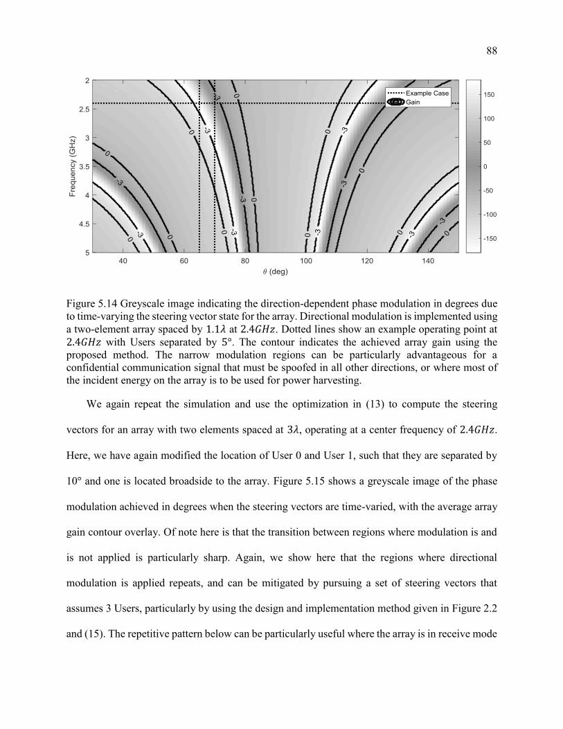
88
Figure 5.14 Greyscale image indicating the direction-dependent phase modulation in degrees due
to time-varying the steering vector state for the array. Directional modulation is implemented using
a two-element array spaced by 1.1𝜆 at 2.4𝐺𝐻𝑧. Dotted lines show an example operating point at
2.4𝐺𝐻𝑧 with Users separated by 5°. The contour indicates the achieved array gain using the
proposed method. The narrow modulation regions can be particularly advantageous for a
confidential communication signal that must be spoofed in all other directions, or where most of
the incident energy on the array is to be used for power harvesting.
We again repeat the simulation and use the optimization in (13) to compute the steering
vectors for an array with two elements spaced at 3𝜆, operating at a center frequency of 2.4𝐺𝐻𝑧.
Here, we have again modified the location of User 0 and User 1, such that they are separated by
10° and one is located broadside to the array. Figure 5.15 shows a greyscale image of the phase
modulation achieved in degrees when the steering vectors are time-varied, with the average array
gain contour overlay. Of note here is that the transition between regions where modulation is and
is not applied is particularly sharp. Again, we show here that the regions where directional
modulation is applied repeats, and can be mitigated by pursuing a set of steering vectors that
assumes 3 Users, particularly by using the design and implementation method given in Figure 2.2
and (15). The repetitive pattern below can be particularly useful where the array is in receive mode

89
and designed for simultaneous wireless information and power transfer. The regularly spaced and
repetitive regions can be advantageous to a receiver with wireless power transfer transmitters and
information transmitters periodically spaced, such as in the layout shown in Figure 3.2.
Figure 5.15: Greyscale image indicating the direction-dependent phase modulation in degrees due
to time-varying the steering vector state for the array. Directional modulation is implemented using
a two-element array spaced by 3𝜆 at 2.4𝐺𝐻𝑧. Dotted lines show an example operating point at
2.4𝐺𝐻𝑧 with one User at broadside and the other at 10° ofrom broadside. The contour indicates
the achieved array gain using the proposed method. The regular spacing of the modulation regions
can be advantageous to communications systems with geometrically planned layouts, such as in
the layout shown in Figure 3.2.
90
Experimentation
The proposed method for directional modulation was experimentally verified in a laboratory
setting using a phased array transmitter and two receivers with single horn antennas. The
experimental setup, including the hardware used and the wireless channels, was calibrated to the
extent possible and practical. It should be noted that the instantaneous channel state information
(CSI) is necessary for implementation of directional modulation as proposed; however, sufficiently
line-of-sight channels free of multipath are sufficient to prove the utility of the proposed method.
The following experiment shows that simple calibration of the wireless channel is sufficient to
achieve directional modulation.
This experiment was performed in coordination between the author and Ryan Christopher of
New Mexico State University. Mr. Christopher provided access to the experimental setup,
including all hardware. Of particular note in this experimental setup are the programmable and
time-variable array steering controls as well as the channel environment with minimal multipath.
Chapter 6

91
The author was responsible for the experiment design, calibration of the wireless channels, and
processing of the experimental results.
6.1 Objective
The objective of this experiment is to verify the differing and direction-dependent effects of
the proposed array control method on the physical layer of wireless information signals. By
verifying the effect on the physical layer, we can extrapolate the ability of the proposed method to
achieve simultaneous wireless information and power transfer and to increase the capacity of
confidential messages over broadcast channels. The time-varying steering vectors induce
direction-dependent phase modulation at the cost of array gain. In this experiment, we demonstrate
selectively inducing binary phase-shift keying (BPSK) modulation to different receivers over a
broadcast channel at will, thereby enabling independent modulation of signals to different
receivers. We also measure the cost of implementing the proposed method by comparing the
achieved array gain to the array gain measured using conventional beam steering.
6.2 Experimental Setup
The experimental setup consists of a transmit antenna array and two receivers. The transmit
array is an array of 6 patch antennas designed for optimum response at a center frequency of
2.35GHz. Each transmit Antenna Element is mated to an Analog Transmit Module that includes
programmable amplifiers, phase-delay circuits, and attenuators. The Analog Transmit Modules are
coherently coupled to the same source using a corporate feed. Throughout each of the experiments,

92
4 of the 6 array elements were effectively disabled by terminating the amplifiers and implementing
the maximum in-path attenuation. During the experiment, the transmit array with two active
elements was oriented in the azimuth plane towards two receivers, each with a single antenna. A
block diagram of the experimental setup is shown in Figure 6.1.
Figure 6.1: Block diagram of the experimental setup, consisting of a transmit antenna array
oriented in the azimuth plane towards two receivers. Each transmit Antenna Element is mated to
an Analog Transmit Module that includes programmable amplifiers, phase-delay circuits, and
attenuators, and is coherently coupled to a signal source using a corporate feed.
The receivers are spaced by 36° about boresight of the array and in the azimuth plane with no
obstacles in line-of-sight between the transmitter and receivers. A photograph of the experimental
setup is shown in Figure 6.2. Microwave absorptive material is placed surrounding the entire
experimental setup to minimize the multipath in the wireless channels. All experiments are
conducted within the unlicensed industrial, scientific and medical (ISM) radio band, at a center
frequency of 2.35GHz.
Analog Transmit Module
Antenna
Element 0
Digital
Phase
Shifter
Digital
Amplitude
Shifter
Transmit
Amplifier
Receiver 1
(User 1)
Broadcast
Channel
MatrixSourceAnalog Transmit Module
Antenna
Element 1
Digital
Phase
Shifter
Digital
Amplitude
Shifter
Transmit
Amplifier
Receiver 0
(User 0)

93
Figure 6.2: Experimental setup consisting of a transmit antenna array (left) and two receivers
(center and right). The transmit array is an array of 6 patch antennas designed for optimum
response at a center frequency of 2.35GHz, each mated to a programmable Analog Transmit
Module that are coherently coupled to the signal source using a corporate feed. Throughout each
of the experiments, 4 of the 6 array elements were disabled by terminating Analog Transmit
Module. Each of the receivers uses a single horn antenna connected directly to a network analyzer.
Image courtesy of Ryan Christopher.
6.3 Calibration
Prior to and throughout the experiments, we calibrate the wireless channel (broadcast channel
matrix), all active and passive components in each Analog Transmit Module, and the Antenna
Elements. One differing aspect between the proposed technique and information-theoretic
approaches to broadcast channel capacity bounds lies in the estimation of the wireless channel. In
these experiments, a line-of-sight channel is setup and precautions are taken to minimize multipath
contribution by covering nearby surfaces with microwave absorptive material. As expected,

94
calibration measurements indicate that the wireless channel can be reasonably predicted by the
array manifold; however, it should be noted that obtaining channel state information is practical in
current wireless communications systems and pure prediction is not required.
We calibrated the entire experimental setup using automated scripts prior to each experimental
collection, including the programmable Analog Transmit Module and the wireless channels. Due
to the static nature of the experimental setup, calibration values remained stable over the course of
the experiments.
6.3.1 Analog Transmit Front End Hardware Calibration
Each of the Analog Transmit Modules used in this experiment resides on a multi-function
Analog Transmit/Receive Board. The programmable phase and amplitude control circuitry within
the Analog Transmit Module was calibrated by measuring the complex transfer function of each
control bit available on each Analog Transmit/Receive Board using a 2-port network analyzer, as
shown in Figure 6.3. Each Analog Transmit/Receive Board can route the input connector to a
passive path, a receive path with low-noise amplifier (LNA), or a transmit path with a power
amplifier (PA) based on the supplied command. Throughout the experiments and calibration, each
Analog Transmit/Receive Board was commanded to activate the transmit path and terminate the
input and outputs of the passive path and the receive path.
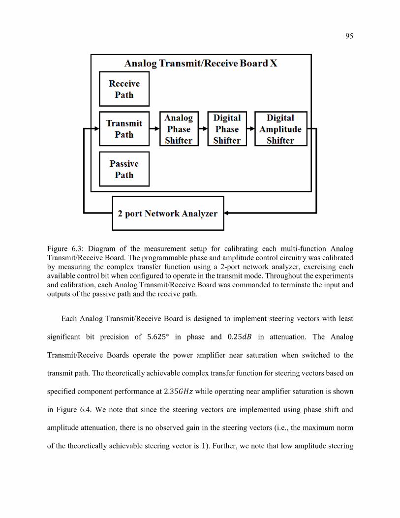
95
Figure 6.3: Diagram of the measurement setup for calibrating each multi-function Analog
Transmit/Receive Board. The programmable phase and amplitude control circuitry was calibrated
by measuring the complex transfer function using a 2-port network analyzer, exercising each
available control bit when configured to operate in the transmit mode. Throughout the experiments
and calibration, each Analog Transmit/Receive Board was commanded to terminate the input and
outputs of the passive path and the receive path.
Each Analog Transmit/Receive Board is designed to implement steering vectors with least
significant bit precision of 5.625° in phase and 0.25𝑑𝐵 in attenuation. The Analog
Transmit/Receive Boards operate the power amplifier near saturation when switched to the
transmit path. The theoretically achievable complex transfer function for steering vectors based on
specified component performance at 2.35𝐺𝐻𝑧 while operating near amplifier saturation is shown
in Figure 6.4. We note that since the steering vectors are implemented using phase shift and
amplitude attenuation, there is no observed gain in the steering vectors (i.e., the maximum norm
of the theoretically achievable steering vector is 1). Further, we note that low amplitude steering

96
vectors are not achievable using this hardware; however, we do not expect this to be a problem
given that low amplitude steering vectors will cause significant loss of array gain, which is
undesirable. A detailed study of the effect of steering vector resolution on directional modulation
performance is suggested for future research.
Figure 6.4: Theoretically achievable steering vectors for the Analog Transmit/Receive Board at
2.35GHz based on specified component control precision of 5.625° in phase and 0.25dB in
attenuation. Since the power amplifier operates near saturation when switched to the transmit path,
and the steering vectors are implemented using phase shift and amplitude attenuation, there is no
observed gain in any of the steering vectors.

97
Though advertised with a minimum achievable phase shift per bit of 5.625°, we measure each
Analog Transmit/Receive Board at closer to 10° minimum achievable phase shift per bit. Though
the MACOM MAPS-010164 6-bit digital phase shifter is rated for operation at 2.35𝐺𝐻𝑧, the
advertised mean root mean square (RMS) phase error at that frequency is approximately 3°. As
such, the achievable steering vectors that can be realized using Analog Transmit/Receive Board
#4 and #9 are shown in Figure 6.5 and Figure 6.6, respectively. The coarse resolution of achievable
steering vectors is common to both Analog Transmit/Receive Board #4 and #9, and limit the
performance of directional modulation.

98
Figure 6.5: Graphical depiction of all possible complex steering vectors that can be realized using
Analog Transmit/Receive Board #4, given measured component performance at 2.35GHz. Though
advertised with a phase shift resolution of 5.625°, calibration of Analog Transmit/Receive Board
#4 shows approximately 10° minimum phase resolution per control bit, likely due to the RMS
phase error performance of the MACOM MAPS-010164 6-bit digital phase shifter. The coarse
resolution of achievable steering vectors limit the performance of directional modulation.
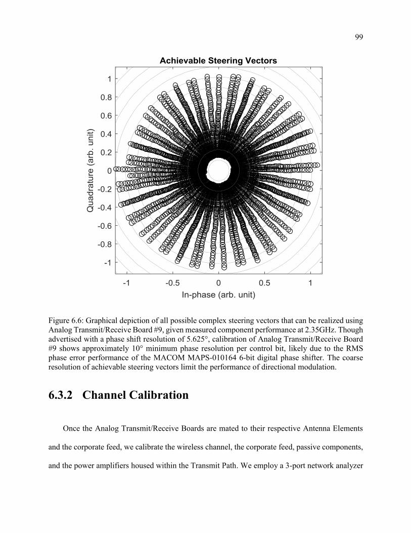
99
Figure 6.6: Graphical depiction of all possible complex steering vectors that can be realized using
Analog Transmit/Receive Board #9, given measured component performance at 2.35GHz. Though
advertised with a phase shift resolution of 5.625°, calibration of Analog Transmit/Receive Board
#9 shows approximately 10° minimum phase resolution per control bit, likely due to the RMS
phase error performance of the MACOM MAPS-010164 6-bit digital phase shifter. The coarse
resolution of achievable steering vectors limit the performance of directional modulation.
6.3.2 Channel Calibration
Once the Analog Transmit/Receive Boards are mated to their respective Antenna Elements
and the corporate feed, we calibrate the wireless channel, the corporate feed, passive components,
and the power amplifiers housed within the Transmit Path. We employ a 3-port network analyzer

100
providing the source to the corporate feed and coherently measuring the output of both receivers,
as shown in Figure 6.7. Each Analog Transmit/Receive Board is software-addressable and
programmable, so we are able to measure each Analog Transmit/Receive Board and Antenna
Element pair independently. Though the array is fitted with 6 Antenna Elements, only 5 Analog
Transmit/Receive Boards were operational, so the unmated Antenna Element and corporate feed
output were terminated to a 50Ω load.
Figure 6.7: Diagram of the experimental setup for calibrating the wireless channels between each
Antenna Element and both receivers. The measurements include the complex transfer functions of
the corporate feed, passive components, and the power amplifiers housed within the Transmit Path
of each Analog Transmit/Receive Board. We use a 3-port network analyzer to coherently record
the output of both receivers while transmitting from each Analog Transmit/Receive Board and
Antenna Element pair independently, with unused elements terminated to a 50Ω load.
One differing aspect between the proposed technique and information-theoretic approaches to
broadcast channel capacity bounds [82] is in the estimation and knowledge of the complex transfer
function induced by the wireless channel. For example, in [82] the wireless channel transfer

101
functions are explicitly assumed to be uniform random variables, then used to compute the
broadcast channel capacity bounds. For the proposed technique, we assume full channel state
information is available to the transmitter; however, it should be noted that given a sufficiently
line-of-sight channel with minimal multi-path contribution, the full channel state information is
not necessary for directional modulation.
Throughout the experiments described in this chapter, line-of-sight channels are setup and
precautions are taken to minimize multipath, as described in Section 6.2. We measure the wireless
channels using the configuration shown in Figure 6.7, and show that the wireless channels can be
reasonably predicted for the 5 Antenna Elements and 2 receivers after a bulk phase rotation, as
shown in Figure 6.8. The wireless channels were predicted using the array manifold shown in (1)
and fit to the measured channels using a minimum mean square error (MMSE) criterion for a bulk
rotation of the channel constellation. Though the calibration results indicate that perhaps a Rician
fading model is more accurate for this experimental setup, a line-of-sight channel model is
assumed. It is important to note that since the proposed method is a beamforming method, the
relative offset between the various wireless channels is critical; however, the bulk rotation
common to all the wireless channels for the Antenna Elements towards a receiver will not affect
the performance of the induced directional modulation. Notwithstanding, we note that obtaining
channel state information is practical and a reasonable requirement in modern wireless
communications systems such that prediction is not required. The tolerance of this method to
multipath is left as a subject of future research.

102
Figure 6.8: Measured wireless channels between 5 Antenna Elements and 2 receivers (Users)
compared to theoretical predictions based on the array manifold. In this manuscript, we assume
the full channel state information for line-of-sight channels with minimal multipath is available to
the transmitter for computation of the steering vectors. These measurements show that the wireless
channels used in this experiment fit sufficiently to a line-of-sight channel model. These
measurements were taken on May 20, 2017.
6.4 Experimental Procedure
Once the Analog Transmit Front End Hardware and Channel calibration measurements have
been obtained, we execute a software function to generate machine-readable command files for
the array, which is detailed in Figure 6.9. We estimate the wireless channel transfer functions from
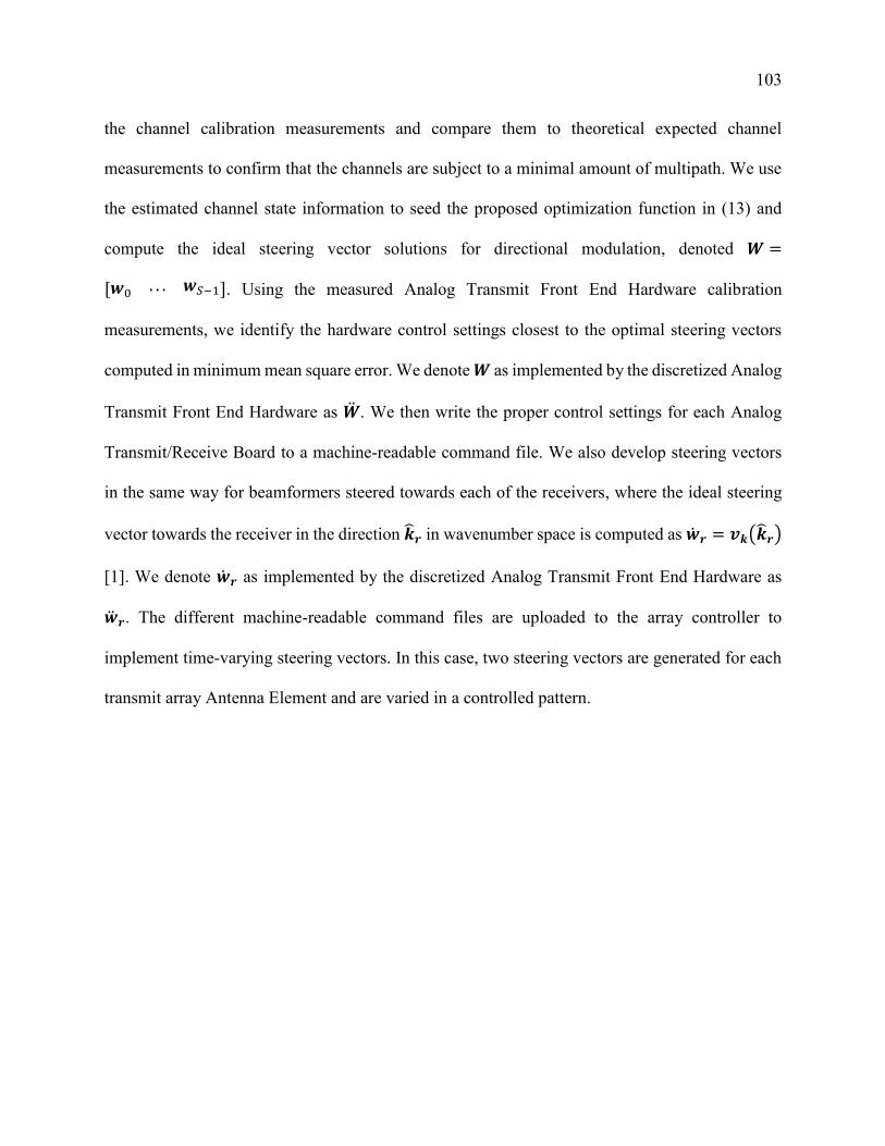
103
the channel calibration measurements and compare them to theoretical expected channel
measurements to confirm that the channels are subject to a minimal amount of multipath. We use
the estimated channel state information to seed the proposed optimization function in (13) and
compute the ideal steering vector solutions for directional modulation, denoted 𝑾 =
[𝒘0 . . . 𝒘𝑆−1]. Using the measured Analog Transmit Front End Hardware calibration
measurements, we identify the hardware control settings closest to the optimal steering vectors
computed in minimum mean square error. We denote 𝑾 as implemented by the discretized Analog
Transmit Front End Hardware as �̈�. We then write the proper control settings for each Analog
Transmit/Receive Board to a machine-readable command file. We also develop steering vectors
in the same way for beamformers steered towards each of the receivers, where the ideal steering
vector towards the receiver in the direction �̂�𝒓 in wavenumber space is computed as �̇�𝒓 = 𝒗𝒌(�̂�𝒓)
[1]. We denote �̇�𝒓 as implemented by the discretized Analog Transmit Front End Hardware as
�̈�𝒓. The different machine-readable command files are uploaded to the array controller to
implement time-varying steering vectors. In this case, two steering vectors are generated for each
transmit array Antenna Element and are varied in a controlled pattern.
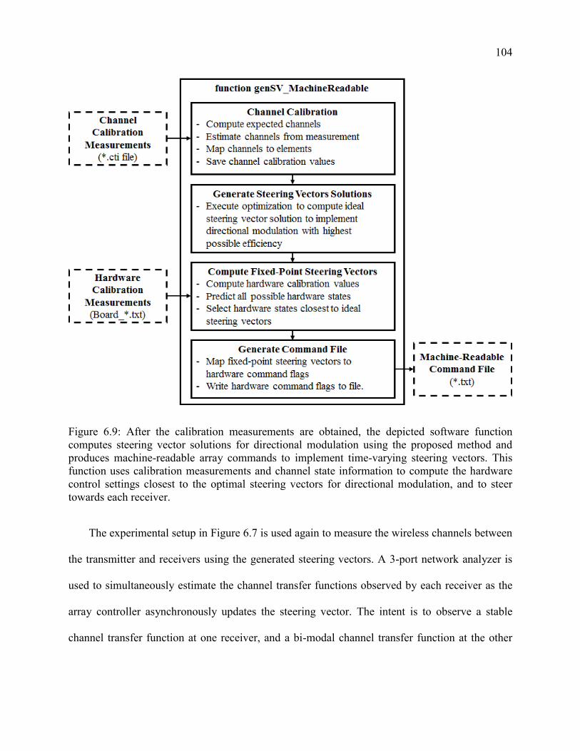
104
Figure 6.9: After the calibration measurements are obtained, the depicted software function
computes steering vector solutions for directional modulation using the proposed method and
produces machine-readable array commands to implement time-varying steering vectors. This
function uses calibration measurements and channel state information to compute the hardware
control settings closest to the optimal steering vectors for directional modulation, and to steer
towards each receiver.
The experimental setup in Figure 6.7 is used again to measure the wireless channels between
the transmitter and receivers using the generated steering vectors. A 3-port network analyzer is
used to simultaneously estimate the channel transfer functions observed by each receiver as the
array controller asynchronously updates the steering vector. The intent is to observe a stable
channel transfer function at one receiver, and a bi-modal channel transfer function at the other

105
receiver while the array is steered by �̈�. The desire is to observe sufficient amplitude and signal-
to-noise ratio at each receiver as compared to the array under �̈�𝟎 and �̈�𝟏.
6.5 Results
To establish a reference peak performance of the array, we implement steering vectors
designed to steer towards Receiver 0, �̈�𝟎, then implement steering vectors to steer towards
Receiver 1, �̈�𝟏. The centroids of each group of measurements are shown in Figure 6.10. As
expected, each Receiver experiences a relatively favorable SNR when the array is steered towards
them, and a poor SNR when the array is steered away. The relative signal strength can be visually
estimated as the absolute distance of the centroids to the origin. In this round of experiments, the
Receivers observed losses of approximately 9𝑑𝐵 and 7𝑑𝐵 when the array was steered away from
them. The SNR loss in computed relative to the average wireless channel transfer functions
measured during the channel calibration, as describe in Section 6.3.2. The average SNR loss
measured at each Receiver subject to different steering vectors is summarized in Table 6.1. In this
case, the orientations of the channels are meaningless since a receiver would synchronize to the
centroid. The transmitter would encode information by inverting the phase of the channel transfer
function. For clarity, Figure 6.10 and Table 6.1 only describe the channel transfer functions
associated with the ‘0’ bit and not the ‘1’ bit.

106
Figure 6.10: Graphical depiction of the wireless channel transfer functions observed by User 0 and
User 1 when the array is subject to a beamformer designed to steer towards User 0 (�̈�𝟎) and a
beamformer designed to steer towards User 1 (�̈�𝟏). The measurements indicate good array
efficiency observed by each User when the array is steered towards and poor efficiency when the
array is steered away.
Table 6.1: Average SNR loss measured by each user for the array subject to each steering vector
relative to peak SNR for conventional beam steering towards each user as measured during the
wireless channel calibration.
Steering Vector 0 (�̈�𝟎) Steering Vector 1 (�̈�𝟏)
User 0 −0.7𝑑𝐵 −6.6𝑑𝐵
User 1 −9.7𝑑𝐵 −0.3𝑑𝐵
107
The steering vectors computed from the optimization in (10) to implement directional
modulation are designed to selectively modulate the wireless channel for User 1 and have minimal
effect on the wireless channel for User 0. The centroids of the measured channel transfer functions
for each of the two steering vectors (�̈�) are shown in Figure 6.11. As expected, the channel transfer
function observed by User 0 is minimally affected as the steering vector is time-varied. In contrast,
User 1 would likely interpret a symbol transition due to the change in steering vector, which results
in an observed phase shift in excess of 170° only for User 1. We assume that each receiver would
synchronize to their received centroids prior to demodulation and decoding. The SNR measured
for each User subject to each steering vector is measured and compared to the maximum measured
beamforming gain throughout the experiments. In all cases, the average SNR loss when
implementing directional modulation was within 3𝑑𝐵 of the average SNR loss when steering
directly towards each User. The average SNR measurements are shown in Table 6.2 and were
nearly identical over thousands of measurements during 3 separate collections.
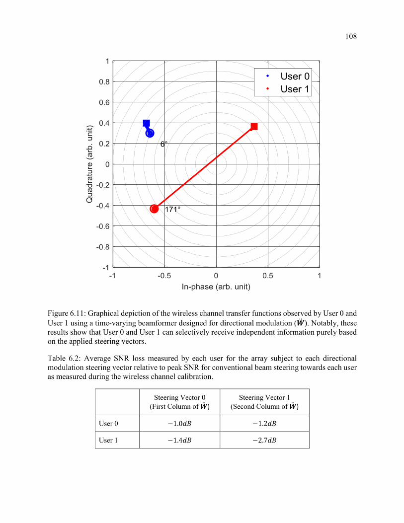
108
Figure 6.11: Graphical depiction of the wireless channel transfer functions observed by User 0 and
User 1 using a time-varying beamformer designed for directional modulation (�̈�). Notably, these
results show that User 0 and User 1 can selectively receive independent information purely based
on the applied steering vectors.
Table 6.2: Average SNR loss measured by each user for the array subject to each directional
modulation steering vector relative to peak SNR for conventional beam steering towards each user
as measured during the wireless channel calibration.
Steering Vector 0
(First Column of �̈�) Steering Vector 1
(Second Column of �̈�)
User 0 −1.0𝑑𝐵 −1.2𝑑𝐵
User 1 −1.4𝑑𝐵 −2.7𝑑𝐵

109
During a third experiment, we attempt to steer the array using both the directional modulation
steering vectors (�̈�) and the individual steering vectors (�̈�𝟎 and 𝒘𝟏̈ ) consecutively and in a
repeating pattern. This experiment will enable direct comparison of these steering vectors to verify
the validity and the efficiency of directional modulation. The centroids of each group of
measurements are shown in Figure 6.12, where the directional modulation channel transfer
function centroids are connected by a line, and the individually steered channel transfer function
centroids are not. Again, as expected, User 0 does not experience a symbol transition as the steering
vector is time-varied, while simultaneously, User 1 would likely interpret a symbol transition given
the change in steering vector, given that a phase shift in excess of 170°. Here, again, we assume
that the receivers would synchronize to their observed centroids. The channel transfer functions
when the array is subject to the steering vectors 𝒘𝟎̈ and 𝒘𝟏̈ outperform directional modulation at
the intended recipient, User 0 and User 1, respectively; however, the unintended recipient observes
reduced SNR. The SNR measured for each User subject to each steering vector is measured and
compared relative to the peak SNR measured when the array is steered directly to that receiver. In
three cases, the SNR loss was less than 1.6𝑑𝐵, and approximately 2.7𝑑𝐵 in the fourth case, as
shown in Table 6.3. The tabulated results were nearly identical over 3 separate collections and
thousands of measurements using the same steering vectors. We recognize that the observed
performance is somewhat decreased due to imperfections in the hardware and fixed-point nature
of the steering vectors that were implemented, and some presence of multipath in the channel
calibration.

110
Figure 6.12: Graphical depiction of the wireless channel transfer functions observed by User 0 and
User 1 using a time-varying beamformer that consecutively induces directional modulation then
steers directly towards User 0 then towards User 1.
Table 6.3: Average SNR loss measured by each user for the array subject to each steering vector
relative to peak SNR for conventional beam steering towards each user as measured during the
wireless channel calibration.
Steering Vector �̈�𝟎
User 0 is the intended
recipient
Steering Vector �̈�𝟏
User 1 is the intended
recipient
Steering Vector �̈�
(Column 1)
Directional
Modulation
Steering Vector �̈�
(Column 2)
Directional
Modulation
User 0 0𝑑𝐵 −6.2𝑑𝐵 −1.0𝑑𝐵 −1.2𝑑𝐵
User 1 −8.6𝑑𝐵 0𝑑𝐵 −1.4𝑑𝐵 −2.7𝑑𝐵

111
Conclusions and Scope of Future Work
7.1 Conclusions
In this dissertation, we develop a passive array beamforming technique to implement
directional modulation. Application of directional modulation to communications systems enables
a receiver to extract information and harvest wireless energy simultaneously from signals
occupying the same time and frequency subspaces. The same technique can also provide a
transmitter with additional PHY-layer secrecy by purposefully overlaying a spoofed signal onto
the transmitted signal in the direction of an eavesdropper. In both applications, this technique
surpasses the state of the art by time-varying the spatial degrees of freedom inherent in an array.
The proposed directional modulation technique enables energy efficient and secure wireless
communications.
Chapter 7

112
We also described and produced simulation and experimental results for a coding technique
that exploits the directional modulation overlay not only as a spoofed signal, but as a second,
legitimate, and confidential signal intended for a second User. The proposed coding technique
can outperform the Dirty Paper Coding technique both in terms of sum rate capacity and secrecy
capacity. Unlike Dirty Paper Coding, the proposed technique time-varies array steering vectors
to achieve a direction-dependent overlay modulation, which eliminates co-channel interference
generated by the transmitter and thus greatly increases the achievable SINR in each channel. We
also showed that the proposed technique exceeds the Sato Bound [17] since the Sato Bound
implicitly assumes no time-varying control or knowledge of the channel via steering vector
manipulation. The proposed technique can benefit IoT systems by increasing the overall secrecy
capacity of a wireless broadcast system without increasing the size, weight, or power consumption
of the devices.
7.2 Topics for Future Research
The following topics are recommended for future research in the interest of further developing
the proposed beamforming method, further characterizing the performance of the proposed
method, and developing extended applications of the proposed method.
113
7.2.1 Effects of Channel State Information and the Channel
Model
Future study of the effects of channel state information and the assumed channel model on the
performance of directional modulation is encouraged. First, the relationship between the accuracy
of the channel state information to the performance of directional modulation should be
established, both in terms of the modulation quality (e.g., modulation error ratio) and in the overall
loss of array gain. Further, the effectiveness of the proposed method should be investigated as the
line-of-sight channel observes increasing amounts of multipath and more closely resembles a
Rician channel then a Rayleigh channel. The proposed method relies on the knowledge of the
relative phase difference between the dominant multipath components of the two users. It may be
possible to overcome loss of the line-of-sight channels if the channels are Rician but sufficiently
sounded, even if the maximum amplitude component is not the line-of-sight component. It is
unclear if the proposed method will maintain effectiveness in a Rayleigh channel environment. As
such, the robustness of the proposed method to varying multipath is suggested as an area of future
research.
7.2.2 Effects of Hardware Implementation
Further study of the effect of steering vector implementation in hardware on the performance
of directional modulation is suggested. First, the discrete nature of the control of amplitude and
phase modulating components can be quantified, and the effect of the discrete implementation on
such performance parameters as modulation error ratio and loss of array gain can be bounded.

114
Second, it is possible that a possibly brute-force, alternative formulation of (13), while possibly
not convex, may provide better performance when the possible solution space is discretized. For
example, amplitude and phase modulation with 6-bit control each has only 4096 possible control
combinations per Analog Transmit/Receive Board. It is feasible to evaluate all of the directional
modulation constraints and the objective function for each of the possible control combinations.
This will not scale favorably to larger dimensions (e.g., additional Antenna Elements, higher
resolution of control); however, these studies may provide simpler, non-optimal implementations
for practical purposes.
7.2.3 Convex Optimization of Steering Vectors for
Directional Modulation
Continued investigation into the capacity of these techniques is recommended. Critical to the
sum-rate capacity and the secrecy capacity of the system relies upon the efficiency of the proposed
technique. The existence of a transformation of (13) that preserves convexity and linearizes the
gradient remains an open problem. The existence of a reformulation of (13) that develops
directional modulation steering vectors with greater secrecy capacity and remains convex should
be investigated.
7.2.4 Effects of Imperfect Synchronization
While unnecessary in the implementation of directional modulation for transmit, future study
of the effects of imperfect synchronization on directional modulation for receive is recommended.
Specifically, the direct effect of imperfect synchronization on power transfer performance and

115
degree of corruption of simultaneous wireless information and power transfer should be studied.
Further, the existence of optimal layout planning for co-channel information and power transfer
should be studied, including the existence of optimal layouts for performance with sub-optimal
synchronization.
7.2.5 Effects of Inequality Constraint Parameters
The selection of the parameter 휀 in the linear inequality constraints for directional modulation
as in (12), (15), and (17), is not only critical to the performance in terms of achieved modulation
error ratio, but also affects the achievable array gain. It is not necessary for the inequality constraint
parameter to be applied uniformly across each inequality constraint. We suggest a future study of
the achievable gain by varying the parameter 휀 in different directions of interest while maintaining
the convexity of Ψ.
7.2.6 Performance Benefits Using Non-Uniform Array
Layouts
Continued investigation and qualification of the performance of the proposed directional
modulation method for an irregular array, possibly sparse or volumetric is recommended. For
example, a swarm of Array Elements that are cooperating for a given mission would be both sparse
and volumetric, and able to change element positions should the need arise. The proposed method
may be applied to increase the performance of the cooperating swarm, or perhaps provide
additional multiple access performance within the swarm. For example, directional modulation
can provide enhanced performance to radar direction finding by directionally-coding the

116
transmitted signal as considered in [51]. Further, non-uniform array layouts that maximize the
utility of these applications should be investigated.
7.2.7 Applications to Multi-Rate, Multiple Access
Communications
The linear inequality constraints and predicted performance for achieving variable symbol
rates to multiple users should be developed. Applications where one user receives a low symbol-
rate communication (e.g., BPSK) and a second user receives high symbol-rate communication
(e.g., QPSK or 16-QAM) should be explored, and may be of particular relevance to military
communications applications.
7.2.8 Additional Laboratory Experimentation
Additional laboratory experimentation to verify and explore the practical implementation of
directional modulation is recommended. Further, more extensive experimentation to validate and
quantify the observed capacity gains of the proposed method over Dirty Paper Coding is suggested.
Lastly, detailed investigation of the stability of solutions of the proposed method over broad swaths
of angular coverage is suggested.

117
Bibliography
[1] H. L. Van Trees, Optimum array processing. New York: Wiley-Interscience, 2002.
[2] Y.-W. P. Hong, P.-C. Lan, and C.-C. J. Kuo, Signal processing approaches to secure physical
layer communications in multi-antenna wireless systems. Springer, 2013.
[3] Q. Li, Q. Zhang, and J. Qin, “Secure Relay Beamforming for SWIPT in Amplify-and-
Forward Two-Way Relay Networks,” IEEE Transactions on Vehicular Technology, vol. 65,
no. 11, pp. 9006–9019, Nov. 2016.
[4] Y. Yang, Q. Li, W.-K. Ma, J. Ge, and P. C. Ching, “Cooperative Secure Beamforming for
AF Relay Networks With Multiple Eavesdroppers,” IEEE Signal Processing Letters, vol. 20,
no. 1, pp. 35–38, Jan. 2013.
[5] N. Yang, S. Yan, J. Yuan, R. Malaney, R. Subramanian, and I. Land, “Artificial Noise:
Transmission Optimization in Multi-Input Single-Output Wiretap Channels,” IEEE
Transactions on Communications, vol. 63, no. 5, pp. 1771–1783, May 2015.
[6] O. N. Alrabadi and G. F. Pedersen, “Directional space-time modulation: A novel approach
for secured wireless communication,” in Communications (ICC), 2012 IEEE International
Conference on, 2012, pp. 3554–3558.
[7] X. Zhou, R. Zhang, and C. K. Ho, “Wireless Information and Power Transfer: Architecture
Design and Rate-Energy Tradeoff,” IEEE Transactions on Communications, vol. 61, no. 11,
pp. 4754–4767, Nov. 2013.

118
[8] A. Salem, K. A. Hamdi, and K. M. Rabie, “Physical Layer Security With RF Energy
Harvesting in AF Multi-Antenna Relaying Networks,” IEEE Transactions on
Communications, vol. 64, no. 7, pp. 3025–3038, Jul. 2016.
[9] Z. Xiang and M. Tao, “Robust Beamforming for Wireless Information and Power
Transmission,” IEEE Wireless Communications Letters, vol. 1, no. 4, pp. 372–375, Aug.
2012.
[10] Q. Li, Q. Zhang, and J. Qin, “Beamforming for Information and Energy Cooperation in
Cognitive Non-Regenerative Two-Way Relay Networks,” IEEE Transactions on Wireless
Communications, vol. 15, no. 8, pp. 5302–5313, Aug. 2016.
[11] I. Krikidis, S. Sasaki, S. Timotheou, and Z. Ding, “A Low Complexity Antenna Switching
for Joint Wireless Information and Energy Transfer in MIMO Relay Channels,” IEEE
Transactions on Communications, vol. 62, no. 5, pp. 1577–1587, May 2014.
[12] R. Zhang and C. K. Ho, “MIMO Broadcasting for Simultaneous Wireless Information and
Power Transfer,” IEEE Transactions on Wireless Communications, vol. 12, no. 5, pp. 1989–
2001, May 2013.
[13] S. Timotheou and I. Krikidis, “Joint information and energy transfer in the spatial domain
with channel estimation error,” in Online Conference on Green Communications
(GreenCom), 2013 IEEE, 2013, pp. 115–120.
[14] M. P. Daly and J. T. Bernhard, “Directional Modulation Technique for Phased Arrays,” IEEE
Transactions on Antennas and Propagation, vol. 57, no. 9, pp. 2633–2640, Sep. 2009.
[15] Y. Ding and V. Fusco, “Directional modulation transmitter synthesis using particle swarm
optimization,” in Antennas and Propagation Conference (LAPC), 2013 Loughborough,
2013, pp. 500–503.
[16] M. P. Daly and J. T. Bernhard, “Directional modulation and coding in arrays,” in Antennas
and Propagation (APSURSI), 2011 IEEE International Symposium on, 2011, pp. 1984–1987.

119
[17] H. Sato, “An outer bound to the capacity region of broadcast channels (Corresp.),” IEEE
Transactions on Information Theory, vol. 24, no. 3, pp. 374–377, 1978.
[18] H. E. Shanks and R. W. Bickmore, “Four-dimensional electromagnetic radiators,” Canadian
Journal of Physics, vol. 37, no. 3, pp. 263–275, 1959.
[19] W. H. Kummer, A. T. Villeneuve, T. Fong, and F. Terrio, “Ultra-low sidelobes from time-
modulated arrays,” Antennas and Propagation, IEEE Transactions on, vol. 11, no. 6, pp.
633–639, 1963.
[20] R. E. Crotty and C. G. Goss, “Side Lobe Response Reducing System,” 3412405, 19-Nov-
1968.
[21] B. L. Lewis and J. B. Evins, “A New Technique for Reducing Radar Response to Signals
Entering Antenna Sidelobes,” Antennas and Propagation, IEEE Transactions on, vol. 31, no.
6, pp. 993–996, 1983.
[22] E. J. Baghdady, “Novel techniques for counteracting multipath interference effects in
receiving systems,” Selected Areas in Communications, IEEE Journal on, vol. 5, no. 2, pp.
274–285, 1987.
[23] Shiwen Yang, Yeow Beng Gan, and T. Peng Khiang, “A new technique for power-pattern
synthesis in time-modulated linear arrays,” IEEE Antennas and Wireless Propagation
Letters, vol. 2, no. 1, pp. 285–287, 2003.
[24] X. Zhu, S. Yang, and Z. Nie, “Full-Wave Simulation of Time Modulated Linear Antenna
Arrays in Frequency Domain,” IEEE Transactions on Antennas and Propagation, vol. 56,
no. 5, pp. 1479–1482, May 2008.
[25] Fondevila, Bregains, Ares, and Moreno, “Optimizing uniformly excited linear arrays through
time modulation,” IEEE Antennas and Wireless Propagation Letters, vol. 3, no. 1, pp. 298–
301, Dec. 2004.

120
[26] A. Babakhani, D. B. Rutledge, and A. Hajimiri, “Transmitter Architectures Based on Near-
Field Direct Antenna Modulation,” IEEE Journal of Solid-State Circuits, vol. 43, no. 12, pp.
2674–2692, Dec. 2008.
[27] M. P. Daly and J. T. Bernhard, “Beamsteering in Pattern Reconfigurable Arrays Using
Directional Modulation,” IEEE Transactions on Antennas and Propagation, vol. 58, no. 7,
pp. 2259–2265, Jul. 2010.
[28] Tao Hong, Mao-Zhong Song, and Yu Liu, “Dual-Beam Directional Modulation Technique
for Physical-Layer Secure Communication,” IEEE Antennas and Wireless Propagation
Letters, vol. 10, pp. 1417–1420, 2011.
[29] M. P. Daly, E. L. Daly, and J. T. Bernhard, “Demonstration of Directional Modulation Using
a Phased Array,” IEEE Transactions on Antennas and Propagation, vol. 58, no. 5, pp. 1545–
1550, May 2010.
[30] Y. Ding and V. Fusco, “BER-driven synthesis for directional modulation secured wireless
communication,” International Journal of Microwave and Wireless Technologies, vol. 6, no.
02, pp. 139–149, Apr. 2014.
[31] V. Pellegrini, F. Principe, G. de Mauro, R. Guidi, V. Martorelli, and R. Cioni,
“Cryptographically secure radios based on directional modulation,” in Acoustics, Speech and
Signal Processing (ICASSP), 2014 IEEE International Conference on, 2014, pp. 8163–8167.
[32] Shiwen Yang, Y.-B. Gan, and Peng Khiang Tan, “Linear antenna arrays with bidirectional
phase center motion,” IEEE Transactions on Antennas and Propagation, vol. 53, no. 5, pp.
1829–1835, May 2005.
[33] Shiwen Yang, Yeow Beng Gan, and Anyong Qing, “Sideband suppression in time-modulated
linear arrays by the differential evolution algorithm,” IEEE Antennas and Wireless
Propagation Letters, vol. 1, no. 1, pp. 173–175, 2002.

121
[34] S. Yang, “Study of Low Sidelobe Time Modulated Linear Antenna Arrays at Millimeter-
Waves,” International Journal of Infrared and Millimeter Waves, vol. 26, no. 3, pp. 443–
456, Mar. 2005.
[35] E. Aksoy and E. Afacan, “Thinned Nonuniform Amplitude Time-Modulated Linear Arrays,”
IEEE Antennas and Wireless Propagation Letters, vol. 9, pp. 514–517, 2010.
[36] P. Rocca, Q. Zhu, E. T. Bekele, S. Yang, and A. Massa, “4-D Arrays as Enabling Technology
for Cognitive Radio Systems,” IEEE Transactions on Antennas and Propagation, vol. 62,
no. 3, pp. 1102–1116, Mar. 2014.
[37] Q. Zhu, S. Yang, R. Yao, and Z. Nie, “Directional Modulation Based on 4-D Antenna
Arrays,” IEEE Transactions on Antennas and Propagation, vol. 62, no. 2, pp. 621–628, Feb.
2014.
[38] S. Yang, Q. Zhu, P. Rocca, and Z. Nie, “Signal-to-noise ratio and time-modulated signal
spectrum in four-dimensional antenna arrays,” IET Microwaves, Antennas & Propagation,
vol. 9, no. 3, pp. 264–270, Feb. 2015.
[39] N. Valliappan, A. Lozano, and R. W. Heath, “Antenna Subset Modulation for Secure
Millimeter-Wave Wireless Communication,” IEEE Transactions on Communications, vol.
61, no. 8, pp. 3231–3245, Aug. 2013.
[40] A. Babakhani, D. B. Rutledge, and A. Hajimiri, “A near-field modulation technique using
antenna reflector switching,” in Solid-State Circuits Conference, 2008. ISSCC 2008. Digest
of Technical Papers. IEEE International, 2008, pp. 188–605.
[41] A. Babakhani, D. Rutledge, and A. Hajimiri, “Near-field direct antenna modulation,” IEEE
Microwave Magazine, vol. 10, no. 1, pp. 36–46, Feb. 2009.
[42] A. H. Chang, A. Babakhani, and A. Hajimiri, “Near-field direct antenna modulation
(NFDAM) transmitter at 2.4 GHz,” in Antennas and Propagation Society International
Symposium, 2009. APSURSI’09. IEEE, 2009, pp. 1–4.

122
[43] J. Lavaei, A. Babakhani, A. Hajimiri, and J. C. Doyle, “A study of near-field direct antenna
modulation systems using convex optimization,” in American Control Conference (ACC),
2010, 2010, pp. 1065–1072.
[44] Y. Zhang, Y. Ding, and V. Fusco, “Sidelobe Modulation Scrambling Transmitter Using
Fourier Rotman Lens,” IEEE Transactions on Antennas and Propagation, vol. 61, no. 7, pp.
3900–3904, Jul. 2013.
[45] V. Fusco and Y. Ding, “Directional modulation transmitter radiation pattern considerations,”
IET Microwaves, Antennas & Propagation, vol. 7, no. 15, pp. 1201–1206, Dec. 2013.
[46] Y. Ding and V. F. Fusco, “Establishing Metrics for Assessing the Performance of Directional
Modulation Systems,” IEEE Transactions on Antennas and Propagation, vol. 62, no. 5, pp.
2745–2755, May 2014.
[47] Y. Ding and V. F. Fusco, “Constraining directional modulation transmitter radiation
patterns,” IET Microwaves, Antennas & Propagation, vol. 8, no. 15, pp. 1408–1415, Dec.
2014.
[48] V. F. Fusco and Y. Ding, “Directional modulation far-field pattern separation synthesis
approach,” IET Microwaves, Antennas & Propagation, vol. 9, no. 1, pp. 41–48, Jan. 2015.
[49] V. Fusco and Y. Ding, “Directional modulation-enhanced retrodirective array,” Electronics
Letters, vol. 51, no. 1, pp. 118–120, Jan. 2015.
[50] T. Hong, M.-Z. Song, and Y. Liu, “RF DIRECTIONAL MODULATION TECHNIQUE
USING A SWITCHED ANTENNA ARRAY FOR COMMUNICATION AND
DIRECTION-FINDING APPLICATIONS,” Progress In Electromagnetics Research, vol.
120, pp. 195–213, 2011.
[51] T. Snow and W. J. Chappell, “Applications for Directional Modulation on a Digital Phased
Array,” in Phased Array Systems & Technology, 2013 IEEE International Symposium on,
2013, pp. 529–533.

123
[52] T. Hong, M. Song, and Y. Liu, “Directional spread-spectrum modulation signal for physical
layer security communication applications: Physical layer security communication,” Security
and Communication Networks, vol. 6, no. 2, pp. 182–193, Feb. 2013.
[53] R. M. Christopher, “OPTIMIZATION OF SYMBOL DISTANCE METRIC IN
DIRECTIONAL MODULATION SYSTEMS,” in International Telemetering Conference
Proceedings, 2016.
[54] Y. Ding and V. F. Fusco, “A Vector Approach for the Analysis and Synthesis of Directional
Modulation Transmitters,” IEEE Transactions on Antennas and Propagation, vol. 62, no. 1,
pp. 361–370, Jan. 2014.
[55] S. S. Haykin and M. Moher, Modern wireless communications. Upper Saddle River, N.J:
Pearson/Prentice Hall, 2005.
[56] Stephen P Boyd and Lieven Vandenberghe, Convex optimization. Cambridge, UK, New
York: Cambridge University Press, 2004.
[57] S. Jontz, “DISA Seeks Software Solution To Manage Spectrum,” Signal, vol. 69, no. 11, pp.
34–36, Jul-2015.
[58] W. C. Brown and R. George, “Rectification of microwave power,” Spectrum, IEEE, vol. 1,
no. 10, pp. 92–97, 1964.
[59] W. C. Brown, “Experiments involving a microwave beam to power and position a
helicopter,” Aerospace and Electronic Systems, IEEE Transactions on, no. 5, pp. 692–702,
1969.
[60] A. H. Sakr and E. Hossain, “Cognitive and Energy Harvesting-Based D2D Communication
in Cellular Networks: Stochastic Geometry Modeling and Analysis,” IEEE Transactions on
Communications, vol. 63, no. 5, pp. 1867–1880, May 2015.

124
[61] S. Lee, R. Zhang, and K. Huang, “Opportunistic Wireless Energy Harvesting in Cognitive
Radio Networks,” IEEE Transactions on Wireless Communications, vol. 12, no. 9, pp. 4788–
4799, Sep. 2013.
[62] I. Krikidis, S. Timotheou, S. Nikolaou, G. Zheng, D. W. K. Ng, and R. Schober,
“Simultaneous wireless information and power transfer in modern communication systems,”
IEEE Communications Magazine, vol. 52, no. 11, pp. 104–110, 2014.
[63] D. W. K. Ng, E. S. Lo, and R. Schober, “Robust Beamforming for Secure Communication in
Systems With Wireless Information and Power Transfer,” IEEE Transactions on Wireless
Communications, vol. 13, no. 8, pp. 4599–4615, Aug. 2014.
[64] A. F. Molisch, Wireless communications. Chichester, West Sussex, U.K.: Wiley : IEEE,
2011.
[65] J. W. Betz, “The Offset Carrier Modulation for GPS Modernization,” in Proceedings of the
1999 National Technical Meeting of The Institute of Navigation, San Diego, CA, 1999, pp.
639 – 648.
[66] X. Zhu and F. Wang, “The signal design of present satellite navigation system and its
inspiration,” 2005, pp. 598557–598557–5.
[67] R. M. Yamada, A. O. Steinhardt, and L. Mili, “Beamforming for Simultaneous Energy and
Information Transfer and Physical-Layer Secrecy,” IEEE Transactions on Wireless
Communications, vol. Submitted, Mar. 2017.
[68] Q. Zhu, S. Yang, R. Yao, and Z. Nie, “A directional modulation technique for secure
communication based on 4D antenna arrays,” in Antennas and Propagation (EuCAP), 2013
7th European Conference on, 2013, pp. 125–127.
[69] R. Poisel, Introduction to communication electronic warfare systems. Boston: Artech House,
2002.
125
[70] R. Poisel, Modern communications jamming: principles and techniques, 2nd ed. Boston:
Artech House, 2011.
[71] C. Cox, An introduction to LTE LTE, LTE-advanced, SAE, VoLTE and 4G mobile
communications. Chichester, West Sussex, United Kingdon ; Hoboken, New Jersey: John
Wiley & Sons, Inc, 2014.
[72] M. Costa, “Writing on dirty paper (corresp.),” IEEE transactions on information theory, vol.
29, no. 3, pp. 439–441, 1983.
[73] G. Caire and S. Shamai, “On the achievable throughput of a multiantenna Gaussian broadcast
channel,” IEEE Transactions on Information Theory, vol. 49, no. 7, pp. 1691–1706, Jul.
2003.
[74] J. Barros and M. R. Rodrigues, “Secrecy capacity of wireless channels,” in Information
Theory, 2006 IEEE International Symposium on, 2006, pp. 356–360.
[75] A. Nordrum, “The Internet of Fewer Things,” IEEE Spectrum, vol. 53, no. 10, pp. 12–13,
2016.
[76] C. E. Shannon, “A Mathematical Theory of Communication,” Bell System Technical Journal,
vol. 27, no. 4, pp. 623–656, Oct. 1948.
[77] G. J. Foschini and M. J. Gans, “On limits of wireless communications in a fading environment
when using multiple antennas,” Wireless personal communications, vol. 6, no. 3, pp. 311–
335, 1998.
[78] T. Cover, “Broadcast channels,” IEEE Transactions on Information Theory, vol. 18, no. 1,
pp. 2–14, 1972.
[79] K. Marton, “A coding theorem for the discrete memoryless broadcast channel,” IEEE
Transactions on Information Theory, vol. 25, no. 3, pp. 306–311, 1979.
126
[80] I. Csiszar and J. Korner, “Broadcast channels with confidential messages,” IEEE
Transactions on Information Theory, vol. 24, no. 3, pp. 339–348, May 1978.
[81] N. Jindal, S. Vishwanath, and A. Goldsmith, “On the duality of Gaussian multiple-access and
broadcast channels,” IEEE Transactions on information Theory, vol. 50, no. 5, pp. 768–783,
2004.
[82] S. Vishwanath, N. Jindal, and A. Goldsmith, “Duality, achievable rates, and sum-rate
capacity of gaussian mimo broadcast channels,” IEEE Transactions on Information Theory,
vol. 49, no. 10, pp. 2658–2668, Oct. 2003.
[83] A. Bennatan and D. Burshtein, “On the fading-paper achievable region of the fading MIMO
broadcast channel,” IEEE Transactions on Information Theory, vol. 54, no. 1, pp. 100–115,
2008.
[84] P. Viswanath and D. N. C. Tse, “Sum capacity of the vector Gaussian broadcast channel and
uplink-downlink duality,” IEEE Transactions on Information Theory, vol. 49, no. 8, pp.
1912–1921, 2003.
[85] F. Oggier and B. Hassibi, “The Secrecy Capacity of the MIMO Wiretap Channel,” IEEE
Transactions on Information Theory, vol. 57, no. 8, pp. 4961–4972, Aug. 2011.
[86] R. Liu and H. V. Poor, “Secrecy Capacity Region of a Multiple-Antenna Gaussian Broadcast
Channel With Confidential Messages,” IEEE Transactions on Information Theory, vol. 55,
no. 3, pp. 1235–1249, Mar. 2009.
[87] J. Brehmer, A. Molin, P. Tejera, and W. Utschick, “A low complexity approximation of the
MIMO broadcast channel capacity region,” in Communications, 2006. ICC’06. IEEE
International Conference on, 2006, vol. 7, pp. 3111–3116.
[88] A. Goldsmith, S. A. Jafar, N. Jindal, and S. Vishwanath, “Capacity limits of MIMO
channels,” IEEE Journal on Selected Areas in Communications, vol. 21, no. 5, pp. 684–702,
Jun. 2003.

127
[89] E. Biglieri, Ed., MIMO wireless communications. Cambridge: Cambridge University Press,
2007.