Embed Size (px)
Citation preview
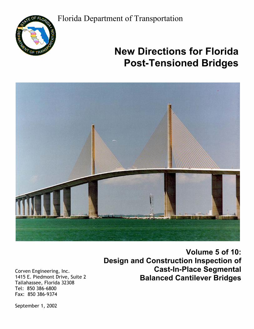
Volume 5 of 10:
Design and Construction Inspection of Cast-In-Place Segmental
Balanced Cantilever Bridges
New Directions for FloridaPost-Tensioned Bridges
Florida Department of Transportation
Corven Engineering, Inc. 1415 E. Piedmont Drive, Suite 2 Tallahassee, Florida 32308 Tel: 850 386-6800 Fax: 850 386-9374
September 1, 2002

Florida Post-Tensioned Bridges 9/1/2002 FINAL REPORT
Volume 5 – Design and Construction Inspection of 2 of 37 Cast-In-Place Segmental Balanced Cantilever Bridges
Preface As a result of recent findings of corrosion of prestressing steel in post-tensioned bridges, the Florida Department of Transportation (FDOT) will be changing policies and procedures to ensure the long-term durability of post-tensioning tendons. The recommendations of the Consultant for revising FDOT policies and procedures is presented in this study entitled, New Directions for Florida Post-Tensioned Bridges. The study will be presented in several volumes, with each volume focusing on a different aspect of post-tensioning or bridge type. Volume 1: Post-Tensioning in Florida Bridges presents a history of post-tensioning in Florida along with the different types of post-tensioned bridges typically built in Florida. This volume also reviews the critical nature of different types of post-tensioning tendons and details a new five-part strategy for improving the durability of post-tensioned bridges. Volumes 2 through 8: Design and Construction Inspection of various types of post-tensioned bridges - applies the five-part strategy of Volume 1 to bridges in Florida. Items such as materials for enhanced post-tensioning systems, plan sheet requirements, grouting, and detailing practices for watertight bridges and multi-layered anchor protection are presented in detail. The various types of inspection necessary to accomplish the purposes of the five-part strategy are presented from the perspective of CEI along with detailed checklists of critical items or activities. Volume 9: Condition Inspection and Maintenance of Florida Post-Tensioned Bridges addresses the specifics of ensuring the long-term durability of tendons in existing and newly constructed bridges. The types of inspections and testing procedures available for condition assessments are reviewed, and a protocol of remedies are presented for various symptoms found. Volume 10: Load Rating Segmental Post-Tensioned Bridges in Florida provides guidance for meeting AASHTO LRFD load rating requirements as they pertain to precast and cast-in-place segmental bridges.
Disclaimer The information presented in this Volume represents research and development with regard to improving the durability of post-tensioned tendons; thereby, post-tensioned bridges in Florida. This information will assist the Florida Department of Transportation in modifying current policies and procedures with respect to post-tensioned bridges. The accuracy, completeness, and correctness of the information contained herein, for purposes other than for this express intent, are not ensured.

Florida Post-Tensioned Bridges 9/1/2002 FINAL REPORT
Volume 5 – Design and Construction Inspection of 3 of 37 Cast-In-Place Segmental Balanced Cantilever Bridges
Volume 5 – Design and Construction Inspection of Cast-in-Place Segmental Balanced Cantilever Bridges
Contents
Preface Disclaimer Contents Introduction Strategy 1 – Enhanced Post-Tensioning Systems
1.1 Qualified Products List 1.2 Three-Level Protection 1.3 Materials 1.4 Internal Tendons – Ducts and Connections
(a) Plastic Ducts (b) Duct Connections
1.5 External Tendons – Ducts and Connections 1.6 Permanent Grout Cap 1.7 Pipes for Grout Ports, Vents and Drains 1.8 Shop Drawings 1.9 Installation 1.10 Pressure Test before Grouting 1.11 Grout Material 1.12 Sealing of Grout Ports, Vents and Drains 1.13 Internal Tendons – Clearances, Dimensions, Details
(a) Spacing between Longitudinal (b) Thickness of Top Slab for Cantilever Tendons (c) Thickness of Bottom Slab for Internal Continuity Tendons (d) Thickness of Slab for Temporary Post-Tensioning Bars (e) Multiple Internal Tendons in Thin Slabs (f) Duct Supports (g) Web Reinforcing and Cantilever and Continuity Tendons (h) Space for Concrete Vibrators
1.14 External Tendons – Clearances, Dimensions, Details
Strategy 2 – Fully Grouted Tendons
2.1 Accessible Anchors 2.2 Grouting of Tendons 2.3 Shop Drawings

Florida Post-Tensioned Bridges 9/1/2002 FINAL REPORT
Volume 5 – Design and Construction Inspection of 4 of 37 Cast-In-Place Segmental Balanced Cantilever Bridges
2.4 Materials – Grout 2.5 Installation 2.6 Grouting Plan 2.7 Grouting Procedure – Top Slab Cantilever and Continuity Tendons 2.8 Grouting Procedure - Bottom Slab Continuity Tendon 2.9 Secondary Vacuum-Assisted Grouting
Strategy 3 – Multi-Level Anchor Protection
3.1 FDOT Standard Drawings 3.2 Shop Drawings 3.3 Materials 3.4 Installation 3.5 Anchors inside a hollow box 3.6 Cantilever and Continuity Tendon Anchorage Blisters 3.7 Anchors at Expansion Joints 3.8 Embedded Face Anchors 3.9 Temporary Protection during Construction
Strategy 4 – Watertight Bridges
4.1 Cast-in-Place (Cold) Joints 4.2 Forming and Filling Temporary Holes in Top Slabs 4.3 Temporary Access Holes 4.4 Expansion Joint Recess and Seat 4.5 Drip Notches and Flanges 4.6 Bottom Slab Drains
Strategy 5 – Multiple Tendon Paths
5.1 Multiple Tendon Paths 5.2 Extra (Corrosion Loss) Post-Tensioning 5.3 Provisional Post-Tensioning 5.4 Construction – Multiple Tendon Paths

Florida Post-Tensioned Bridges 9/1/2002 FINAL REPORT
Volume 5 – Design and Construction Inspection of 5 of 37 Cast-In-Place Segmental Balanced Cantilever Bridges
Introduction The Florida Department of Transportation is committed to continued development of post-tensioned bridges as a viable solution for many of Florida’s infrastructure needs. The challenge, in light of recent instances of corrosion of some post-tensioning tendons, is to consistently produce prestressed bridges with highly durable post-tensioning. The Department defines a durable structure as one that serves its design purpose over the intended life of the bridge, while requiring only routine inspection and maintenance. Consistent production of durable structures and durable post-tensioning is affected by many factors that become critical at different stages in the life of the structure. The selection of materials and post-tensioning details by the Designer has the first and foremost impact on the resulting durability. During construction, the Contractor’s ability to effectively build in accordance with the plans and specifications is critical to creating durable structures. Finally, over the service life of the bridge, inspectors and maintainers must be familiar with symptoms and remedies available to ensure the long-term durability of structures with post-tensioning tendons. Past performance of post-tensioned bridges in Florida has shown that improper consideration for important design, construction and maintenance features leads to reduced durability. Furthermore, even where post-tensioning tendons have been installed and maintained with existing appropriate standards of care on the part of designers, contractors, and maintainers, there have still been instances where high durability has not been achieved. Consequently, new procedures are needed to create a design, construction and maintenance environment that consistently produces durable post-tensioned bridges. In response, the Department is taking a new direction to produce more durable post-tensioned bridges, based on a five-part strategy. The components of this strategy, and the requirements that further define them, are devised to raise the level of performance in design, construction, and maintenance to ensure consistency and confidence in post-tensioned structures. The new direction, expressed by the five strategy components, is shown in Figure 1.1.
Figure 1.1 – Five-part strategy for more durable post-tensioned bridges in Florida. Volume 1: Post-Tensioning in Florida Bridges introduced the development of the five-part strategy for more durable post-tensioned bridge in Florida. This volume applies these strategies to a particular type of post-tensioned construction.

Florida Post-Tensioned Bridges 9/1/2002 FINAL REPORT
Volume 5 – Design and Construction Inspection of 6 of 37
Cast-In-Place Segmental Balanced Cantilever Bridges
Volume 5 – Cast-in-Place Segmental Balanced Cantilever Post-tensioning for cast-in-place segmental balanced cantilever bridges consists primarily of cantilever and continuity tendons. Cantilever tendons are typically internal to the concrete and located within the top slab in order to maximize the eccentricity from the neutral axis for structural efficiency. Cantilever tendons extend from a typical segment on one end of the cantilever to its counterpart on the other, resulting in a maximum number of tendons over the pier. Continuity tendons are typically internal to the concrete at mid-span and side-span closures and are anchored in internal blisters. Continuity tendons may also be placed inside the box girder void, external to the concrete. These external tendons typically anchor in pier segment diaphragms, are draped between the diaphragms and deviators and are straight at midspan in order to provide eccentricities required by design. Details of these continuity tendons are similar to post-tensioning tendons used in span-by-span construction. This volume provides direction for achieving more durable post-tensioned bridges by applying the Department’s five strategies to the specifics of cast-in-place segmental balanced cantilever construction. Strategy 1 – Enhanced Post-Tensioning Systems Strategy 1 requires that all post-tensioning systems be fabricated using enhanced post-tensioning systems. The Designer implements the strategy by incorporating appropriate details in the plans. The CEI checks that these systems are correctly installed during construction, with allowance for Contractor’s chosen post-tensioning system and means and methods of construction. Summarizing, the responsibilities for meeting Strategy 1 include:
• Designer - incorporate the policies and standards into the Contract Drawings that utilize enhanced post-tensioning system components, materials and appropriate structural details.
• Contractor - install all components and materials in accordance with the Contract
Drawings, approved Shop Drawings, Specifications and QPL. • CEI – inspect the work to verify compliance with the Contract Documents and approved
Shop Drawings as required. Advise the Contractor of any areas of non-compliance. Specific requirements for enhanced post-tensioning systems are provided in the following sections. 1.1 Qualified Products List (Requirement 1.A) In the future, all post-tensioning systems must be selected from the Department’s Qualified Products List (QPL). New components and new post-tensioning systems must be pre-approved

Florida Post-Tensioned Bridges 9/1/2002 FINAL REPORT
Volume 5 – Design and Construction Inspection of 7 of 37
Cast-In-Place Segmental Balanced Cantilever Bridges
by the Department prior to use in any application. This requirement is to be enforced throughout construction. 1.2 Three Level Protection (Requirement 1.B) Enhanced post-tensioning systems require three levels of protection using the barriers defined in Volume 1 “Post-Tensioning in Florida Bridges”. As both internal and external tendons are used in this type of bridge, requirements for both are provided. Internal Tendons: Components of the protection system depend upon whether the duct is within the concrete of the segment or at joints between the cast-in-place segments. The three-levels of protection for these two cases are:
• Within the segments: (1) Fully grouted tendon. (2) Impervious plastic duct. (3) Concrete cover.
• At cast-in-place joint faces* and closures: (1) Fully grouted tendon. (2) Effective continuity of the impervious plastic duct. (3) Concrete cover.
*At joint faces, internal tendon ducts protrude into next segment and are connected with sealed duct connectors. External Tendons: Components of the protection system depend upon whether the duct is embedded within or is outside the concrete. The three-levels of protection for these two cases are:
• Duct embedded within the concrete: (1) Fully grouted tendon. (2) Steel pipe. (3) Concrete cover.
• Duct outside the concrete:
(1) Fully grouted tendon. (2) Impervious plastic pipe. (3) Enclosure within the surrounding, watertight and drained, hollow box.
Combined Tendons: Tendons that are both external (unbonded) and internal (bonded) over a significant length are no longer permitted in Florida. Unlike typical external tendons, these combined tendons are virtually impossible to replace. Levels of Protection:

Florida Post-Tensioned Bridges 9/1/2002 FINAL REPORT
Volume 5 – Design and Construction Inspection of 8 of 37
Cast-In-Place Segmental Balanced Cantilever Bridges
The first level of protection, Level (1), is provided by filling the annular space between the duct and strands with pre-approved grout. Refer Strategy 2 “Fully Grouted Tendons” below for these requirements. The second level of protection, Level (2), is provided by using impervious ducts meeting the following requirements:
• For internal tendons – use corrugated plastic duct (per Specifications and QPL) with positively sealed connections.
• For external tendons - use smooth plastic pipe and steel pipe (per Specifications and QPL) with positively sealed connections.
To achieve the third level of protection, Level (3), provide concrete cover in accordance with FDOT requirements or enclose the tendon within the hollow box girder. Refer to Strategy 4 “Watertight Bridges” below for these requirements. Also, in order to accommodate internal tendons, adopt recommended clearances, dimensions and details herein (Sections 1.13 and 1.14 below). 1.3 Materials (Requirements 1.A through F) Responsibilities regarding materials for enhanced post-tensioning systems are:
• Designer - incorporate the policies and standards into the Contract Drawings and Specifications that utilize enhanced post-tensioning system components and materials.
• Contractor – make sure that all materials and components comply with the Standard
Specifications and the QPL. These include, but are not limited to, post-tensioning steel, ducts (plastic ducts, plastic pipes, steel pipes), anchors, duct and anchor connections (couplings), grout pipes and connections, and grout. Also assure compliance of: − non-shrink, high-bond, high-strength, air-cured concrete for filling holes for
equipment or temporary access holes, − epoxy grout for filling grout recesses and encasing anchors (pour-backs), including
coatings for sealing areas of concrete or pour-backs. Keep records of submittals, test reports, approved component deliveries, and track materials and components from delivery through installation in the bridge. Provide CEI with copy of all records.
• CEI - verify that materials and components comply with Specifications and/or FDOT “Qualified Products List” and keep proper records of submittals, test reports, component deliveries and installation in the bridge.
1.4 Internal Tendons – Ducts and Connections (a) Plastic Ducts (Requirement 1.C) Use corrugated plastic duct of high-density polypropylene (HDPP) with continuous spiral or hoop ribs at frequent and regular intervals to provide positive mechanical interlock, enhancing bond between the concrete, duct and grout. HDPP plastic is to contain material to protect against degradation from ultra-violet light. Duct is to be thermally stable for the range of

Florida Post-Tensioned Bridges 9/1/2002 FINAL REPORT
Volume 5 – Design and Construction Inspection of 9 of 37
Cast-In-Place Segmental Balanced Cantilever Bridges
temperatures anticipated for the life of the structure. Duct is to have a minimum wall thickness of 0.08 inches (2 mm). Plastic duct is to be pre-approved as a part of the post-tensioning system. (b) Duct Connections (Requirements 1.C and 1.D) Use positively sealed couplings between embedded ducts and anchors and between any separate pieces of plastic duct. Duct tape does not serve as a positive seal in joining pieces of duct or duct to anchorage. 1.5 External Tendons – Ducts and Connections External tendons may be used in Cast-in-Place Segmental Balanced Cantilever bridges as continuity or future tendons. Refer to Volume 3, “Design and Construction Inspection of Precast Segmental Span-by-Span Bridges” for requirements concerning:
• Plastic Pipe for External Tendons. • Steel Pipes for External Tendons. • Diabolo Deviators for External Tendons. • Pipe Connections for External Tendons.
1.6 Permanent Grout Cap (Requirement 1.F) Provide all post-tensioning tendon anchors with a permanent, heavy duty, plastic grout caps mechanically secured and sealed against the anchor plate with a compressible, neoprene o-ring. Show details of a typical permanent grout cap on the Contract Drawings in accordance with FDOT Standard Drawings. Fully fill permanent cap with grout. Provide grout outlet vent of ¾” minimum diameter in the cap. Permanent grout cap is to completely cover the anchor plate and head. For strand tendons, the anchor head is the wedge plate, wedges and strand tails. For bar tendons, the anchor head is the nut and bar tail. Before installing the tendon, temporary caps may be used and then be replaced by permanent caps after stressing but before grouting. Show details of a typical permanent grout cap on the Contract Drawings in accordance with FDOT Standard Drawings. 1.7 Pipes for Grout Ports, Vents and Drains (Requirement 1.D) Pipes for grout ports, vents and drains are necessary to allow the escape of air, water, bleed-water and the free flow of grout. Use pipe with an inner diameter of at least 3/4 inch for strand tendons and 3/8 inch for single bar tendons. Pipe is to be flexible, HDPE or HDPP plastic material compatible with that of the main plastic duct for the tendon. Plastic components are not to react with concrete or encourage corrosion of the post-tensioning steel, and must be free of all water-soluble chlorides. Connect grout pipes to ducts and anchor components in a manner that creates a seal and does not allow leaks or ingress of water, chlorides or other corrosive agents. To facilitate inspection of complete filling of a tendon with grout, direct grout vents at high points (crests) to exit the top (riding surface) or other appropriate surface. Also, provide caps and seals

Florida Post-Tensioned Bridges 9/1/2002 FINAL REPORT
Volume 5 – Design and Construction Inspection of 10 of 37
Cast-In-Place Segmental Balanced Cantilever Bridges
to all vents to prevent ingress of water or corrosive agents into the tendon. For locations of grout ports, vents and drains see Strategy 2, “Fully Grouted Tendons” below. 1.8 Shop Drawings (Requirements 1.A through D, F and G) Shop Drawings are required for the integration of approved post-tensioning systems (i.e. post-tensioning supplier’s information and details), reinforcement, post-tensioning, and other embedded items (including those for the Contractor’s chosen “means and methods” of construction) for cast-in-place segments. Shop Drawings responsibilities include:
• Contractor - submit the necessary “Shop Drawings” to the Engineer (Designer) for review and approval.
• Designer - review the Shop Drawings and other relevant information and notify the
Contractor and the CEI of its acceptability.
• CEI - coordinate and keep a record of submittals and responses. 1.9 Installation (Requirements 1.A through 1.G) During fabrication at the Bridge Site, installation shall include but not be limited to: Ducts For Internal Tendons: During fabrication make sure that ducts are:
• Installed to correct profile (line and level) within specified tolerances. • Installed to connect correct duct location in bulkhead with correct duct location in match-
cast segment. • Correctly aligned with respect to the orientation of the segment in the casting cell and
the direction of erection. • Tied and correctly supported at frequent intervals. • Connected with positively sealed couplings between pieces of duct and between ducts
and anchors*. Aligned with sealed couplers at temporary bulkheads.
Ducts For External Tendons: During fabrication make sure that embedded parts (i.e. steel pipes in deviators and diaphragms) are:
• Installed to correct profile (line and level) within specified tolerances. • Tied and correctly supported at frequent intervals. • Connected with positively sealed couplings between pieces of duct and between ducts
and anchors*. • Properly aligned and sealed* at faces of diaphragms and deviators.
During installation make sure that:

Florida Post-Tensioned Bridges 9/1/2002 FINAL REPORT
Volume 5 – Design and Construction Inspection of 11 of 37
Cast-In-Place Segmental Balanced Cantilever Bridges
• Ducts have positively sealed connections between external plastic and steel pipes and between individual lengths of plastic pipe*.
• Match-cast joints are properly prepared and sealed with epoxy (refer to Strategy 4 “Watertight Bridges” below).
(* Note - duct tape does not qualify as a seal although it may be used for temporary support purposes.)
Cover – make sure that cover is correct to rebar and ducts (longitudinal and transverse). Anchors – for internal and external tendons, make sure that anchors are:
• The correct type and size for the type and size of tendon used. • Supplied with permanent, heavy duty, plastic caps with o-ring seal. • Properly aligned and well supported by formwork. • When required, set in a recess (anchor pocket or block-out) of correct size, shape and
orientation. • Provided with correct bursting reinforcement at correct location and spacing.
Grout injection ports, outlet vents and drains – make sure that all injection ports, grout vents and duct drains are installed correctly, in particular that:
• They are of correct type and size. • They are correctly located, connected and sealed to ducts. • Ports or vents at anchors are oriented correctly. • Grout pipes are taken to proper exit surface. • Grout pipes, ducts and connections are sealed before concrete is placed. • (Refer also to Strategy 2 “Fully Grouted Ducts” below).
Epoxy Joints – sealed epoxy joints are not normally used in cast-in-place construction. However, if necessary, refer to Volume 2, “Design and Construction Inspection of Precast Segmental Balanced Cantilever Bridges”. Post-Tensioning Tendons - for Cast-in-Place Balanced Cantilever Bridges – make sure that:
• Ducts are clear for installation (for internal tendons in particular, ducts may be tested by passing through a suitably sized torpedo prior to installing the tendons).
• Number and size of strands (or bar) per tendon is correct. • Strands (or bars) are satisfactory (i.e. no rust etc.) per specification. • Longitudinal PT tendons are installed in their correct duct locations. • Anchor plates and wedges (or nuts) are properly installed on each strand (or bar). • For tendons anchoring in cast-in-place concrete, check that the strength is satisfactory
for stressing. • At cast-in-place closures, concrete attains the required minimum strength before
stressing continuity tendons. • Tendons are stressed in the correct sequence to the required force and elongation as
specified on the plans, the approved shop drawings or erection manual.

Florida Post-Tensioned Bridges 9/1/2002 FINAL REPORT
Volume 5 – Design and Construction Inspection of 12 of 37
Cast-In-Place Segmental Balanced Cantilever Bridges
• All stressing records are made and kept per specifications. Temporary Protection of Post-Tensioning Tendons – Make sure that tendons are properly protected by approved temporary protection in accordance with FDOT Standard Specification B460 from the time they are installed in the ducts to the time of grouting (whether stressed or not). Grout Caps – Permanent plastic grout caps shall be installed prior to tendon installation to keep ducts clean and dry. Caps shall be removed for tendon installation and replaced prior to grouting. Temporary caps may be used if they are replaced by permanent caps before grouting. 1.10 Pressure Test before Grouting (Requirement 1.G) Pressure test all duct assemblies prior to grouting - preferably before installing tendons. Run tests in accordance with the Standard Specifications, with caps installed and vents plugged and check for possible leaks. Properly seal all leaks as necessary before grouting. If the test is run after installing and stressing the tendon it may be very difficult to repair leaks and make a proper seal. 1.11 Grout Material (Requirement 1.E) All grout is to be pre-bagged and pre-approved in accordance with FDOT Standard Specification 938. Grout must be fresh, handled, stored and mixed properly for use in accordance with FDOT Specifications for Post-Tensioning and Grouting. 1.12 Sealing of Grout Ports, Vents and Drains – (Requirements 1.B, 1C, 1D) In order to maintain the integrity of the duct system and its effectiveness as a barrier, all grout ports, vents and drains must be properly terminated and sealed.
• Designer - show details and/or include post-tensioning Standard Drawings into the Contract Drawings.
• Contractor - follow and implement details provided on the Contract Plans or approved
Shop Drawings.
• CEI - check that this work is performed properly. One detail for sealing grout ports, vents and drains is shown in Figure 5.1. Requirements for this detail include: (1) At all grout vents or ports that exit or enter the top slab, provide a recess not less than 2
inches or more than 3-1/2 inches in diameter around the pipe. Make depth of recess not less than 2-1/2 inches or more than 3 inches from the initial roadway surface before grinding and grooving - i.e. final depth of recess after ½ inch of surface has been removed by grinding and grooving to be not less than 2 inches or more than 2-1/2 inches.
(2) Provide a separate recess around each port or vent pipe of each tendon. Do not merge recesses into one large one. Keep each recess separate from an adjacent one by at

Florida Post-Tensioned Bridges 9/1/2002 FINAL REPORT
Volume 5 – Design and Construction Inspection of 13 of 37
Cast-In-Place Segmental Balanced Cantilever Bridges
least 6 inches of concrete (edge to edge of recesses) so that if a recess or pipe is breached only on tendon will be at risk. Multiple grout pipes attached to an individual tendon at one location (such as a grout pipe from an anchor trumpet and grout pipe from cap attached to that anchor) may be housed in one recess.
(3) Provide sides of each recess with an irregular or corrugated finish to ensure a good mechanical bond (in addition to chemical bond with filler.
(4) Form recess with a material that can be easily removed such as corrugated polyethylene or other suitable material.
(5) After grout from both primary and secondary grouting has hardened, trim grout pipes that exit through top slab to 1 inch above bottom of recess.
(6) Seal trimmed grout pipes with permanent plastic cap (or plug) screwed or glued to pipe. (7) Remove all traces of recess forming material and thoroughly clean sides and bottom of
each recess to sound, dry concrete surface.
Figure 5.1 – Sealing grout ports and vents in top slabs.
c). Filling Pocket b). Pocket Preparation
• Fill Recess With Approved Filler
• Grind & Groove
Top Seal Recess 2½” Dia. X 2” Deep (min.)
• Cut Grout Pipe 1” Below Final Surface (Min.)
• Remove Recess Former • Clean & Roughen Sides • Insert Seal Plug or Cap
a). Grout pipe connection to tendon
Final Deck Surface
Cast Surface

Florida Post-Tensioned Bridges 9/1/2002 FINAL REPORT
Volume 5 – Design and Construction Inspection of 14 of 37
Cast-In-Place Segmental Balanced Cantilever Bridges
(8) Fill each recess with an approved low modulus, high-strength, high-bond, sand-filled epoxy grout selected from the Department’s Qualified Product List.
(9) In deck and other top, horizontal surfaces use a flow-able epoxy mix with the above characteristics (8) and allow it to set and cure properly before grinding and grooving.
(10) For grout pipes exiting vertical surfaces and soffit, use a stiffer epoxy mix that may be applied with a trowel and secured with a suitable form. Use a form surface that does not adhere to the epoxy (wax paper coating or similar).
1.13 Internal Tendons - Clearances, Dimensions, Details (Requirements 1.B, 1.C) (a) Spacing between Longitudinal Ducts (Requirement 1.B) Provide a center-to-center distance of 8 inches, twice the outside tendon duct diameter or the outside duct diameter plus 4-1/2 inches - whichever is the greatest. This is to facilitate duct connections during casting and maintain the integrity of concrete between ducts. (b) Thickness of Top Slab for Cantilever Tendons (Requirement 1.B) At the location of the longitudinal post-tensioning duct (or ducts) furthest from the web, provide a minimum slab thickness of 9 inches or greater to accommodate:
• Top surface grinding and grooving. • Concrete cover. • Thickness of longitudinal distribution reinforcing. • Thickness of the transverse post-tensioning duct, assuming that the top transverse
rebar lies within the plane of the transverse post-tensioning and is not thicker than the transverse duct. Allow for rib thickenings on post-tensioning ducts.
• Overall outside diameter of longitudinal post-tensioning ducts. • Thickness of the bottom transverse rebar, assuming that the bottom longitudinal
rebar lies above the bottom transverse rebar within the zone for the longitudinal post-tensioning duct.
• Bottom Cover. • An overall construction tolerance allowing for accumulation of tolerances on sizes
and thicknesses not greater than the largest individual tolerance or more than ½ inch.
Increase thickness as necessary to accommodate the above accounting for actual sizes of components. (c) Thickness of Bottom Slab for Internal Continuity Tendons (Requirement 1.B) At the location of the longitudinal post-tensioning duct (or ducts) furthest from the web, provide a minimum slab thickness of 9 inches or greater to accommodate applicable provisions above. (d) Thickness of Slab for Temporary Post-Tensioning Bars (Requirement 1.B) At the location of internal, temporary post-tensioning bars provide a minimum slab thickness of 9 inches and meet the following additional requirements:

Florida Post-Tensioned Bridges 9/1/2002 FINAL REPORT
Volume 5 – Design and Construction Inspection of 15 of 37
Cast-In-Place Segmental Balanced Cantilever Bridges
• When temporary post-tensioning bars are located within a slab, then PT bars and components must not interfere with transverse post-tensioning tendons.
• At locations of post-tensioning bars, the vertical position and sizes must fit within the available overall thickness allowing for needs as those for main longitudinal ducts.
(e) Multiple Internal Tendons in Thin Slabs (Requirement 1.B) As the number of continuity tendons in a thin bottom slab increases, there is a risk of inducing a splitting crack or spall originating in the plane of ducts initiated by minor misalignments and wobble. Web reinforcing extending into the bottom slab controls this tendency near the web/bottom slab intersection. However, away from the webs, provide local rebar (#3 rebar or D4 wire) loops or links at ends of ducts and at intervals of approximately 2 feet along each duct. These bars may also serve as duct supports. (f) Duct Supports (Requirements 1.B and 1.C) Provide duct supports at intervals of 2 feet (or per recommendations of the duct supplier) when the ducts cannot be directly tied to either the top or bottom mat of reinforcing. Supports may be #3 rebar or D4 wire. Bars may be any convenient shape (straight, U, L or Z) and set at any convenient angle or slope providing cover is not violated. Provide duct supports in bottom slabs to prevent ducts being displaced laterally by wet concrete when placed in directly in the slab or down through the webs. (g) Web Reinforcing and Cantilever and Continuity Tendons (Requirement 1.B) Web and slab reinforcement must be detailed to avoid conflicts that may occur as longitudinal tendons move laterally from anchor locations to other positions in the top and bottom slabs. This may require several different bar shapes along each segment for web bars on the inside and outside faces of the web and lateral bars on the underside of the top slab and top of the bottom slab or fillet. This applies particularly to top cantilever and continuity tendons and to bottom continuity tendons. As far as possible, standardize duct trajectories and bar shapes to facilitate detailing and assembly. (h) Space for Concrete Vibrators (Requirement 1.B) Detail reinforcement to provide clearance for concrete aggregate and access for stick-type concrete vibrators in congested and heavily reinforced zones such as anchor blocks and diaphragms. Allow at least 3 inches clearance for inserting vibrators. 1.14 External Tendons – Clearances, Dimensions, Details (Requirements 1.B, 1.C) Refer to Volume 3, “Precast Segmental Span-by-Span Bridges” for recommended minimum dimensions and details for expansion joint segments and for segments containing deviators. Strategy 2 – Fully Grouted Tendons This strategy requires that all post-tensioning tendons in cast-in-place segmental balanced cantilever bridges be completely filled with grout. Tendons must be stressed and grouted in

Florida Post-Tensioned Bridges 9/1/2002 FINAL REPORT
Volume 5 – Design and Construction Inspection of 16 of 37
Cast-In-Place Segmental Balanced Cantilever Bridges
within the time period allowed in the Standard Specifications. To ensure compliance with Strategy 2:
• Designer - incorporate details and requirements in the Contract Drawings to facilitate fully grouted tendons.
• Contractor - install all components and grout in accordance with the Contract Drawings,
approved Shop Drawings, Specifications and QPL. • CEI – inspect the work to verify compliance with the Contract Documents and approved
Shop Drawings as required. Advise the Contractor of any areas of non-compliance. 2.1 Accessible Anchors – (Requirement 2.A) All anchors for both internal and external post-tensioning tendons are to be accessible throughout all construction operations, up to and including the installation and grouting of permanent plastic grout caps. Specific requirements for the accessibility of anchorages in cast-in-place segmental balanced cantilever bridges include but are not limited to:
• Provide a 2’ lateral clear dimension from the sides of the anchor plate for a length along the tendon of 1’-3” for dead end (non-stressing) anchorages. For live (stressing) anchors provide clearance for tendon installation and stressing jacks.
• Anchors for internal cantilever and continuity tendons in blisters on the interior of the
bridge are readily accessible for inspection during construction (and subsequent maintenance inspection) from within the interior of the box section. Provide a minimum of 12 inches from the end of the segment to anchor blocks (Figure 5.7). Anchor blisters are the preferred alternative to embedded face anchors.
• Longitudinal internal cantilever tendons anchored in face-anchors requiring block-outs
extending to the top slab are susceptible to water intrusion and are not accessible for inspection. Top slab blockouts at anchorages are not permitted in new construction.
• An alternative to anchoring cantilever tendons in blisters is to use embedded face
anchors (Figure 5.2). The anchor recess in this detail does not extend to the riding surface of the segment. Instead, two grout vents, one from the anchorage and one from the grout cap extend to a top slab recess for appropriate grouting and inspection. Recesses shall be filled with sand-filled epoxy grout after all tendons grouting operations are complete.
• Anchors in blisters and at diaphragms in interior pier segments, within a hollow box are
directly accessible for construction and maintenance inspection. Anchors on outside surfaces and at expansion joints are embedded under pour-backs. In this case, it is acceptable to remove the seal-coat and concrete pour-back to access the permanent grout cap and anchor head for maintenance inspection. The pour-back and seal coats must be restored following such inspection.
Anchors for new construction are to have an inspection port to accommodate probes and/or

Florida Post-Tensioned Bridges 9/1/2002 FINAL REPORT
Volume 5 – Design and Construction Inspection of 17 of 37
Cast-In-Place Segmental Balanced Cantilever Bridges
bore-scope equipment. Although it is desirable to have access for inspection, poorly sealed inspection ports may be potential points of entry for contaminants or chlorides. Consequently, keep the number of deliberately introduced inspection ports (and grout vents) at or near anchors to a minimum.
Figure 5.2 – Embedded Face Anchor. 2.2 Grouting of Tendons – (Requirements 2.B and 2.C) To help ensure that tendons are fully grouted, specific details and procedures for grouting must be shown on the Contract Drawings, addressed in the Specifications and enforced during construction. In accordance with the FDOT Standard Drawings on the Contract Drawings:
• Require all anchors to have temporary seals or caps to keep debris out of ducts during construction prior to grouting.
• Show locations of all low point grout injection ports, outlet vents and drains. • Show direction of grouting, taking into account the longitudinal profile of the tendon
allowing for the profile of the bridge. • Locate the grout injection port at the lowest point of the tendon profile, accounting for
bridge profile. • If two or more low points are at equal elevations then select one for the injection port and
provide drains at the others. • Provide outlet vents at all high point crests and between 3 to 6 feet beyond the crest in
the direction of grouting. • Locate injection ports, vents and drains on ducts so as to allow free drainage and free
flow of grout unimpeded by the presence of the tendon - whether of strands or bars. • Locate drains at all low points. • Locate drains on bottom one third of duct. • Orient anchors so that the grout vent or injection port is at the top. • Require all internal ducts for temporary longitudinal post-tensioning be fully grouted
Anchor Outlet Grout Cap
Anchor
Segment
Segment Anchor
Grout Cap

Florida Post-Tensioned Bridges 9/1/2002 FINAL REPORT
Volume 5 – Design and Construction Inspection of 18 of 37
Cast-In-Place Segmental Balanced Cantilever Bridges
during construction whether the PT remains in place or not and whether stressed or not. Ducts may be moist at the time of grouting, but all freestanding water must be removed before grouting begins. This minimizes the risk of excess water compromising the grout mix, causing bleed or voids. Drains at all low points are required to facilitate removal of freestanding water. Examples of application to typical internal tendons for cast-in-place segmental balanced cantilever bridges are given in Sections 2.7 and 2.8 below. 2.3 Shop Drawings (Requirements 2.A, 2.B, 2.C) Shop Drawing responsibilities include:
• Contractor – submit necessary “Shop Drawings” to the Engineer (Designer) for review and approval.
• Designer - review the Shop Drawings and other relevant information and notify the
Contractor and CEI of its acceptability. • CEI – coordinate and keep a record of submittals and responses and check that the
correct details are followed – e.g. that grout ports, vents and drains are correctly installed.
On Shop Drawings, show injection ports, grout vents and drains at locations in accordance with details shown on the Contract Drawings and required by the Specifications. In particular show:
• Port or vent type and size (e.g. plastic / diameter). • Location, connection and seal to ducts. • Grout pipes taken to proper exit surface. • Grout pipes, ducts and connections to be sealed before concrete is placed. • Anchors oriented so that ports and vents are to the top and remain accessible not only
for grout installation but also for inspection and checking for complete filling by grout. 2.4 Materials – Grout (Requirements 2E, 2.F, 2.G and 1.E) In existing structures, corrosion damage to tendons has been found at locations of incomplete grouting. Major contributors to voids in tendons include significant bleed water and entrapped air. Much research and effort has been invested in improving the performance of grout to reduce bleed-water and air voids. Consequently, Strategy 1 requires that all grout must be pre-bagged and pre-approved in accordance with FDOT Standard Specification 938. Careful attention to proper mixing, injection and venting procedures is required in order not to negate the benefits of improved pre-bagged grout materials. 2.5 Installation (Requirements 2.A through 2.G) Responsibilities regarding installation include:

Florida Post-Tensioned Bridges 9/1/2002 FINAL REPORT
Volume 5 – Design and Construction Inspection of 19 of 37
Cast-In-Place Segmental Balanced Cantilever Bridges
• Designer – make sure that the Contract Documents address installation of post-tensioning duct system components and grout.
• Contractor - install anchors, grout injection ports, outlet vents and drains in accordance
with the Contract Drawings or approved Shop Drawings or approved Grouting Plan.
• CEI - inspect the installation of grout injection ports, outlet vents and drains for compliance. Make sure grouting is carried out in accordance with the approved Grouting Plan, Shop Drawings, Specifications and QPL. Witness the acceptability of the grouting on Contractor’s records and keep a separate copy.
Specific installation requirements include:
• Grouting to be done only by qualified personnel. • Prior to grouting, ducts to be pressure tested for leaks (can be done prior to installing the
tendon). • Cross-flow or leaks are sealed. • Consistency of grout mix (flow cone) to be satisfactory before injection (use moist cone). • Grout to be injected at lowest point of tendon profile. • Rate of injection in accordance with the Specifications. • Grout to be evacuated at each vent in turn until consistency is same as that being
injected (test evacuated grout using flow-cone, as necessary). • Pressure to be held at 75 psi for two minutes – checked for leaks and fixed. • If no leaks are present, reduce pressure to 5 psi and wait 10 minutes to allow entrapped
air to flow to high points. • Open vents to release any air or bleed water. • Pressure to be pumped to 30 psi and locked off to allow initial set. • After set, grout caps to be checked and any voids completely filled. (Do not remove cap
except for unusual circumstances.) • After set, vents and anchors to be probed, inspected and any voids filled by secondary
vacuum grouting. Application of these requirements to different types of tendons in cast-in-place segmental balanced cantilever bridges is provided in Sections 2.7 and 2.8 below. 2.6 Grouting Plan (Requirements 2.A through 2.G) Grouting Plans shall be developed for all bridges and implemented during construction. Responsibilities regarding the Grouting Plan include:
• Contractor – prepare and submit a “Grouting Plan” according to the requirements of the Specification for Post-Tensioning (B460).
• CEI - record submittals, review and notify the Contractor of acceptability of Grouting
Plan. The CEI may seek an opinion from the Designer regarding the Grouting Plan. However, the CEI has responsibility for review and approval of the Contractor’s plan.
The Grouting Plan must address (but is not necessarily limited to):

Florida Post-Tensioned Bridges 9/1/2002 FINAL REPORT
Volume 5 – Design and Construction Inspection of 20 of 37
Cast-In-Place Segmental Balanced Cantilever Bridges
• Grouting procedures to be followed on site (may be separate grouting plans). • Qualifications and Certification of Grouting Personnel (at the site). • Proposed grout material and reports of qualification tests (must be to QPL). • Equipment for mixing and testing daily grout production. • Stand-by equipment. • Accessibility of anchors for injection and evacuation of grout and inspection of anchor for
completeness of filling (follow details per FDOT Standard Drawings, the Contract Plans or approved Shop drawings).
• Embedded Face Anchors - extra precautions for grouting and sealing embedded face anchors (see 3.8 below).
• Means of pressure testing duct system for leaks and sealing as necessary. • Sequence of injecting and evacuating grout for each tendon type - i.e. longitudinal
cantilever, top continuity, bottom continuity, per examples below - or others. (For external tendons, see Volume 3, “Precast Segmental Span-by-Span Bridges”.)
• Injection of grout at the low point of each profile. • Direction of grout injection and sequence of closing vents. • Provisions for grouting of a group of tendons*. • Means of checking or ensuring all tendons are completely filled. • Means and details for sealing grout inlets, vents and drains – particularly in top deck
(riding) surface. • Procedure for secondary (vacuum) grouting. • Forms or other means of keeping records of grouting operations (supply copy to CEI for
corroboration and witness). • Temporary PT - procedures to ensure that all internal ducts used for temporary post-
tensioning bars for erection are fully grouted at the end of erection, whether bars remain in place or not and whether stressed or not.
* Note: Provision for group grouting may be necessary in the event of potential cross-flow between internal tendons. Furthermore, group grouting may be preferred for efficiency and quality control of operations in some cases. Prior to grouting a group of internal tendons, ensure that there is sufficient supply of materials and back-up equipment in case of breakdown. Simultaneous grouting of a group of internal tendons must combine operations for all proposed tendons in the group, recognizing that injection will be done at several injection ports, in sequence or in parallel, with multiple outlet vents requiring closing in sequence after evacuation of grout of required consistency. External tendons used in cast-in-place balanced cantilever bridges are to be grouted one at a time. 2.7 Grouting Procedure - Top Slab Cantilever and Continuity Tendons (Requirements
2.B, 2.C, 2.E, 2.F, 2.G) Figure 5.3 illustrates typical top slab cantilever and continuity tendons where the bridge is on a rising longitudinal gradient. Applying the above requirements to this example:
• Take into account longitudinal gradient and establish intended direction of grouting. • Orient both end anchors (A and D) so that grout injection and evacuation port is at top. • Provide grout injection port at lowest, end anchor, (A). • Provide a grout outlet vent at the highest point of the tendon profile (C). • Provide outlet vent at the end anchor (D).

Florida Post-Tensioned Bridges 9/1/2002 FINAL REPORT
Volume 5 – Design and Construction Inspection of 21 of 37
Cast-In-Place Segmental Balanced Cantilever Bridges
• If the tendon is longer than 150 feet, provide and intermediate vent near mid-length (B). • Show direction of grouting. • Show sequence of closing vents.
Figure 5.3 – Grouting top slab cantilever and continuity tendons After construction of cast-in-place segments, but prior to installation of post-tensioning tendons, the system should be blown out using clean, oil-free air and the ducts tested with a torpedo in accordance with the Standard Specifications. If satisfactory, post-tensioning tendons may then be installed and tensioned to force in the required sequence. Grouting Operation – (top slab cantilever or continuity tendon); (1) Open all vents (A through D, including intermediate vent B) and check that there is no
free water in the ducts – if there is, then blow out with oil free air. (2) Choose lowest point at which to inject grout (if two low points are at equal elevations,
then select one (A) and but leave other (D) open. (3) Mix grout and perform QA/QC material field tests per specifications. (4) Inject grout at selected port (i.e. point A). (5) Inject grout at a steady rate in accordance with the Specifications. (6) Allow air, excess water and grout to flow freely from intermediate vent (B) until
consistency is satisfactory per specifications. Then close vent (B) and continue pumping at steady rate.
(7) Allow air, excess water and grout to flow freely from vent (C = vent at high point of tendon duct) at a satisfactory consistency per specifications. Then close vent (C) and continue pumping at steady rate.
(8) Allow air, water and grout to flow from final anchor vent (D) until consistency is satisfactory per specifications. Then close vent (D).

Florida Post-Tensioned Bridges 9/1/2002 FINAL REPORT
Volume 5 – Design and Construction Inspection of 22 of 37
Cast-In-Place Segmental Balanced Cantilever Bridges
(9) Pump to a pressure of 75 psi – hold for two minutes and check for grout leaks. If leaks are indicated by reduced pressure then fix the leaks.
(10) If no leaks are present, reduce pressure to 5 psi for 10 minutes to allow entrapped air to flow to the high points.
(11) Open vent (B) to release any accumulated air or bleed water. If necessary, pump grout in again until grout flows consistently from vent (B). Then close vent (B). (Normally grouting pressures should be approximately 80 to 100 psi. Do not exceed a grouting pressure of 150 psi.)
(12) Open vent (C) to release any accumulated air or bleed water. If necessary, pump grout in again until grout flows consistently from vent (C). Then close vent (C).
(13) Repeat at final anchor vent (D). (14) Pump up pressure and lock off at 30 psi. (15) Allow grout to take an initial set. (16) Probe each vent - for any vents not completely filled, or where nearby voids are
suspected, implement vacuum-assisted, secondary grouting of unfilled zones. (Refer to “Secondary, Vacuum Assisted Grouting” - below.) (17) After completion of both primary and secondary vacuum assisted grouting (if
implemented) of tendons, seal all grout injection ports, grout outlet vents and drain vents. (See “Sealing of Grout Ports, Vents and Drains”.)
2.8 Grouting Procedure - Bottom Slab Continuity Tendon (Requirements 2.B, 2.C, 2.E,
2.F, 2.G) Figure 5.4 illustrates a continuity tendon in the bottom slab of a variable depth bridge with a high point at mid-span. Applying the above requirements to this example:
• Take into account longitudinal gradient and establish intended direction of grouting. • Orient both end anchors (A and E) so that grout outlet vent is at top. • Provide grout outlet vent at end anchor, (A). • Provide grout injection port (B) at low point of profile. This may enter from inside
superstructure box section. (Note – (B) may consist of a drain and separate grout vent or port. If, say, B1 is the drain and B2 is the injection port at B then B1 is on bottom of duct and connects through soffit, whereas B2 is on top half of duct: likewise for (D) = D1, D2.)
• Provide an intermediate grout outlet vent (C) at the highest point of the tendon profile or near the mid-length of the tendon if the tendon is longer than 150 feet.
• Provide another injection port (D) if tendon profile is more than 20 inches lower than intermediate vent (C) and end anchor vent (E).
• Provide outlet vent at the end anchor (E). • Show direction of grouting. • Show sequence of closing vents.

Florida Post-Tensioned Bridges 9/1/2002 FINAL REPORT
Volume 5 – Design and Construction Inspection of 23 of 37
Cast-In-Place Segmental Balanced Cantilever Bridges
Figure 5.4 – Grouting bottom slab continuity tendons
After construction of cast-in-place segments and completion of cast-in-place closure, but prior to installation of post-tensioning tendons, the system should be blown out using clean, oil-free air and the ducts tested with a torpedo in accordance with the Standard Specifications. If satisfactory, post-tensioning tendons may then be installed and tensioned to force in the required sequence. Grouting Operation – (bottom slab continuity tendon) (1) Open all vents (A, B1 (drain), B2 (port), C, D1 (drain), D2 (vent), E) and check that there
is no free water in the ducts – if there is, then blow out with oil free air. (2) Choose lowest point at which to inject grout (if two low points are at equal elevations,
then select one (say, B2) and but leave other (D2) open. Close (B1 and D1). (3) Mix grout and perform QA/QC material field tests per specifications. (4) Inject grout at selected port (i.e. point B1). (5) Inject grout at a steady rate in accordance with the Specifications. (6) Allow air, excess water and grout to flow freely from anchor vent (A) until consistency is
satisfactory per specifications. Then close vent (A) and continue pumping at steady rate.
(7) Allow air, excess water and grout to flow freely from vent (C = vent at high point of tendon duct) at a satisfactory consistency per specifications. Then close vent (C) and continue pumping at steady rate.
(8) Allow air, excess water and grout to flow freely from vent (D2) at a satisfactory consistency per specifications. Then close vent (D2) and continue pumping at steady rate.
(9) Allow air, water and grout to flow from final anchor vent (E) until consistency is satisfactory per specifications. Then close vent (E).
(10) Pump up to a pressure of 75 psi – hold for two minutes and check for grout leaks. If leaks are indicated by reduced pressure, then fix the leaks.
(11) If no leaks are present, reduce pressure to 5 psi for 10 minutes to allow entrapped air to flow to the high points.
B1
B2
D1
D2

Florida Post-Tensioned Bridges 9/1/2002 FINAL REPORT
Volume 5 – Design and Construction Inspection of 24 of 37
Cast-In-Place Segmental Balanced Cantilever Bridges
(12) Open vent (A) to release any accumulated air or bleed water. If necessary, pump grout in again until grout flows consistently from vent (A). Then close vent (A). (Normally grouting pressures should be approximately 80 to 100 psi. Do not exceed a grouting pressure of 150 psi.)
(13) Open vent (C) to release any accumulated air or bleed water. If necessary, pump grout in again until grout flows consistently from vent (C). Then close vent (C).
(14) Repeat at vent (D2) and final anchor vent (E). (15) Pump up pressure and lock off at 30 psi. (16) Allow grout to take an initial set. (17) Probe each vent - for any vents not completely filled, or where nearby voids are
suspected, implement secondary, vacuum-assisted, grouting. (Refer to “Secondary, Vacuum Assisted Grouting” - below.) (18) After completion of both primary and secondary vacuum assisted grouting (if
implemented) of tendons, seal all grout injection ports, grout outlet vents and drain vents. (See “Sealing of Grout Ports, Vents and Drains”).
2.9 Secondary, Vacuum-Assisted, Grouting (Requirement 2.G) After primary grouting has been done, all anchors, ports and vents must be inspected and probed. If a void is found, then it must be completely filled with grout using vacuum-assisted grouting. Figure 5.5 illustrates principal details of vacuum injection connections. The procedure is as follows: (1) After the grout has set, open each vent in turn and probe to see if duct and vent is full. (2) Where any void is found, introduce additional grout by vacuum assisted means. (3) Attach a T-connector to the exit vent and attach to it two lines, each with a shut-off valve.
Attach grout injection pipe to one of them. Attach vacuum pump to other. (4) With the grout valve closed and vacuum valve open, draw a vacuum to evacuate any air
or bleed water. (5) When no more air or water can be withdrawn, switch valves and inject grout under
pressure up to 75 psi – but no more. (6) When secondary grout fills voids, reduce pressure to between 30 psi and 40 psi, and
close vents. (7) Repeat, in turn, at each voided vent as necessary. (8) After completion of both primary and (when implemented) secondary vacuum-assisted
grouting, seal all grout injection ports, grout outlet vents and drain vents. (See “Sealing of Grout Ports, Vents and Drains”).

Florida Post-Tensioned Bridges 9/1/2002 FINAL REPORT
Volume 5 – Design and Construction Inspection of 25 of 37
Cast-In-Place Segmental Balanced Cantilever Bridges
Figure 5.5 – Details of Vacuum Grouting Connections Strategy 3 – Multi-Level Anchor Protection Significant corrosion of post-tensioning tendons has resulted from lack of adequate protection at anchorages. Many early balanced cantilever bridges have top slab cantilever tendons anchored on the end faces of the segments (i.e. “face anchors”). These anchors required block-outs, typically extending to the roadway surface, to provide access for grouting. The block-outs were then filled with concrete, burying the anchor. Shrinkage of the pour-back concrete often led to separation of this concrete from the segment, leaving the anchors susceptible to leaks and potential corrosion. To help mitigate this and other corrosion issues, Strategy 3 requires that all anchors shall have a minimum of four levels of corrosion protection. In this context a “level” is not necessarily a layer of material, but rather it is a step taken to ensure protection. A level may be a layer created by a material (such as a pour-back) or it may be a layer made up of one or more coats of a sealing compound or it may be action taken to seal a cold joint. For hollow box girder structures, a distinction is made between anchors inside a hollow box away from direct exposure to corrosive elements and anchors directly exposed to water and windborne salts. Responsibilities in meeting the requirements of Strategy 3 are:
• Designer - incorporate details and requirements in the Contract Drawings to provide the necessary levels of anchor protection.

Florida Post-Tensioned Bridges 9/1/2002 FINAL REPORT
Volume 5 – Design and Construction Inspection of 26 of 37
Cast-In-Place Segmental Balanced Cantilever Bridges
• Contractor - install all components and materials in accordance with the Contract Drawings, approved Shop Drawings, Specifications and QPL. Correct execution and completeness of the work involved is the sole responsibility of the Contractor.
• CEI – inspect the work to verify compliance with the Contract Documents and approved
Shop Drawings as required. Advise the Contractor of any areas of non-compliance. 3.1 FDOT Standard Drawings (Requirement 3.A) Show anchor protection on the Contract Drawings in accordance with the FDOT Standard Drawings. 3.2 Shop Drawings (Requirements 3.A, 3.B, 3.C) Shop Drawings and other relevant information (e.g. manufacturer’s catalogue data) are required for the post-tensioning system. Anchor protection details on Shop Drawings must comply with that shown on the Contract Plans, in accordance with the FDOT Standard Drawings. For cast-in-place segmental balanced cantilever construction, relevant information (such as dimensions, angles, sizes, cover etc. for anchor pockets, blisters or block-outs) must also be integrated into the segment Shop Drawings for cast-in-place segments as appropriate. Shop Drawing responsibilities include:
• Contractor - submit the necessary “Shop Drawings” to the Engineer (Designer) for review and approval.
• Designer - review the Shop Drawings and other relevant information and notify the
Contractor and CEI of its acceptability.
• CEI - coordinate and keep a record of submittals and responses. 3.3 Materials (Requirements 3.A, 3.B, 3.C) Responsibilities regarding materials for anchor protection include:
• Designer – make sure that the Contract Documents address and require the proper materials for anchor components and protection.
• Contractor - ensure that all materials and components comply with the Contract Plans,
Specifications, FDOT Qualified Products List and the approved Shop Drawings. This includes but is not necessarily limited to: grout, permanent plastic grout caps, epoxy grout for pour-backs to anchors and seal coatings as necessary. Also, keep records of submittals, test reports, approved component deliveries, and track materials and components from delivery through installation at the bridge site.
• CEI - verify that materials and components comply with contract requirements. Check
and record submittals, test reports, component deliveries and installation at the bridge site.

Florida Post-Tensioned Bridges 9/1/2002 FINAL REPORT
Volume 5 – Design and Construction Inspection of 27 of 37
Cast-In-Place Segmental Balanced Cantilever Bridges
3.4 Installation (Requirements 3.A, 3.B, 3.C) Responsibilities regarding installation of anchor protection include:
• Designer – make sure that the Contract Documents address proper installation for anchor components and protection.
• Contractor - install components and materials in accordance with the Contract Drawings,
approved Shop Drawings and Specifications. • CEI – inspect the work to verify compliance with the Contract Documents and approved
Shop Drawings as required. Advise the Contractor of any areas of non-compliance. Specific requirements for installation are addressed in Sections 3.5 through 3.8, below. 3.5 Anchors inside a hollow box - (Requirements 3.A, 3.B, 3.C) Typical anchor locations that fall into this category include (Figure 5.6):
• Anchors in blisters typically at the intersection of the web with the top or bottom slab. • Anchors in interior diaphragms or deviator ribs. • Face-anchors in recesses permanently open to the interior hollow core.
Provided that the structure is sealed from leaks through the bridge deck and is drained at all low spots so that water cannot accumulate against anchorages, the four-levels of anchor protection are provided by:
• Grout. • Permanent grout cap. • Elastomeric seal coat. • Surrounding box structure.
Specific requirements for anchors inside a hollow box girder include:
• Correct grout (per FDOT QPL) properly installed to completely fill tendon and anchor. • Permanent grout cap of high density plastic, of the correct size and mechanically
secured and sealed against the anchor plate with a compressible neoprene O-ring. • Permanent grout cap fully filled with grout. • Elastomeric seal coat selected from FDOT QPL. • Seal coat applied over the cap, over the edge of anchor plate and overlapping onto
adjacent structural concrete by a minimum of 12 inches all around the anchor plate. • The surrounding box-structure designed, detailed and built properly to be ventilated,
watertight and drained.

Florida Post-Tensioned Bridges 9/1/2002 FINAL REPORT
Volume 5 – Design and Construction Inspection of 28 of 37
Cast-In-Place Segmental Balanced Cantilever Bridges
Figure 5.6 – Anchor protection for interior anchors 3.6 Cantilever and Continuity Tendon Anchorage Blisters (Requirements 3.A, 3.B, 3.C) For anchors of cantilever and continuity tendons in blisters, meet the requirements of Section 3.5 and the following additional requirements (Figure 5.7):
• Standardize exterior shape and size of anchor blisters for forming. • Longitudinally, locate anchor blisters as far as possible from segment joints
commensurate with (a) the necessary geometry for the tendon path and radius to enter the slab and (b) the minimum segment length at the anchor (web) location allowing for the pie-shape shortening due to plan curvature of the bridge, if any. This also depends upon the standard length chosen for segments.
• Reinforce anchor blisters to resist bursting and radial force effects as necessary. • Provide duct supports for ducts that cannot be directly tied to adjacent rebar. • Provide a drip groove in the soffit of the top slab around upper anchor blisters to
intercept possible water path from adjacent joint and take water to web.

Florida Post-Tensioned Bridges 9/1/2002 FINAL REPORT
Volume 5 – Design and Construction Inspection of 29 of 37
Cast-In-Place Segmental Balanced Cantilever Bridges
Figure 5.7 – Anchor protection for cantilever tendons anchored in blisters 3.7 Anchors at expansion joints - (Requirements 3.A, 3.B, 3.C) At expansion joints where an anchor or concrete containing anchors is directly exposed to windborne spray and water the four levels of anchor protection are:
• Grout. • Permanent grout cap. • Encapsulating pour-back. • Elastomeric seal coat.
Particular requirements for anchors at expansion joints:
• Correct grout (per FDOT QPL) properly installed to completely fill tendon and anchor. • Permanent grout cap of high density plastic, of the correct size and mechanically
secured and sealed against the anchor plate with a compressible neoprene O-ring. • Permanent grout cap fully filled with grout. • The pour-back encapsulating the anchor and grout-cap of an approved, high-strength,
high-bond, low-shrink, sand-filled epoxy grout selected from FDOT QPL. • Pour-back to provide minimum cover over cap of 1-1/2 inch.
12” min.
Seal Coat

Florida Post-Tensioned Bridges 9/1/2002 FINAL REPORT
Volume 5 – Design and Construction Inspection of 30 of 37
Cast-In-Place Segmental Balanced Cantilever Bridges
• For an individual anchor in a recess, surface of pour-back be even with adjacent face of diaphragm or anchor block.
• For a group of anchors, similar individual recesses or, a single enclosing pour-back to encase all anchors in the group.
• A single enclosing pour-back shall be secured to concrete substrate with embedded reinforcement (screw coupled rebar may be used) in order to ensure bond.
• Shape and dimensions of single enclosing pour-back be even with adjacent features of structural concrete with chamfers at all outside corners.
• All concrete surfaces of recesses and pour-back substrates be cleaned and roughened prior to casting pour-backs.
• All finished surfaces of pour-backs and adjacent structural concrete shall be properly prepared to receive seal-coats.
• An approved elastomeric seal coating (per FDOT QPL) be applied over the pour-back overlapping onto adjacent structural concrete by a minimum of 12 inches all around.
Also, protect anchors from dripping water at expansion joints. (Note - a drip flange provides a positive, protective edge for the top of the seal coat.) In coastal areas, consider providing additional protection by means of skirts or baffles at expansion joints to minimize the direct effect of wind borne spray. Typical details for anchor protection at expansion joints is shown in Figure 5.8.
Figure 5.8 – Anchorage protection of exterior tendons. 3.8 Embedded Face Anchors (Requirement 3.A, 3.B, 3.C) Embedded face anchors may be used provided that they are designed, detailed and installed in such a manner as to provide the required four-levels of anchor protection. Embedded face anchors must be located in recessed anchor pockets provided in one or both adjacent

Florida Post-Tensioned Bridges 9/1/2002 FINAL REPORT
Volume 5 – Design and Construction Inspection of 31 of 37
Cast-In-Place Segmental Balanced Cantilever Bridges
segments. These pockets (Figure 5.2) must fully enclose the anchor head and permanent grout cap and ensure that:
• There are no permanent openings of the pocket to any surface (interior or exterior). • There are at least 3½ inches of structural (match-cast) concrete cover above any pocket
to the top slab riding surface for integrity of concrete and epoxy application - (more depth may be needed for other structural reasons).
• Concrete surfaces of the anchor pocket recess are properly cleaned and prepared prior to casting pour-back material.
• Appropriate grout (per FDOT QPL) is properly installed to completely fill tendon and anchor.
• Permanent grout caps are used consisting of high density plastic, mechanically secured against the anchor plate with a compressible neoprene O-ring.
• Permanent grout cap are fully filled with grout. • The pour-back encapsulating the anchor and grout-cap and filling the anchor pocket
recess to be an approved, high-strength, high-bond, low-shrink, sand-filled epoxy grout.
When effectively anchored in recessed anchor pockets, the four levels of anchor protection are provided by:
• Grout. • Permanent grout cap • An approved pour-back to fully fill the anchor pocket. • Concrete cover above and around the pocket.
One method for grouting and sealing embedded face anchors include (Figure 5.2): (1) Install outlet on anchor and bring up through the recess in deck. (2) Install oversized inspection port/outlet (1” to 2” dia.) and bring the port to the same
recess in the deck as the outlet for the anchor. The outlet shall provide access to the anchor pocket (recess / block-out) created by the pocket former.
(3) Cast segment. (4) After erection of segment and installation of permanent tendons, and before erection of
the next segment, install plastic grout cap on anchor plate and attach cap vent pipe through the oversized port.
(5) Grout tendon. Grouting may be done after erection of subsequent segments but with time constraints established in FDOT Standard Specifications.
(6) Check that anchor and cap are full of grout. (7) After grouting tendon, drill anchor outlet and inspect for fullness of grout using a
borescope. If not full, use vacuum grouting to fill voids. (8) Trim grout pipe to approximately ½” above base of deck recess. Backfill drilled outlet
from bottom up with epoxy and insert plug or cap to grout pipe. (9) Remove grout pipe to grout cap and insert plug into hole in cap. Temporarily plug
oversized access hole to anchor block-out at deck level to keep block-out clean and dry prior to filling with grout.
(10) After erection of the next segment and after the tendon has been grouted, fully fill the anchor pocket (block-out) to the top of the oversized access port using an approved, high-strength, high-bond, low-shrink, sand-filled epoxy grout or a pre-bagged, pre-approved grout in accordance with FDOT Standard Specification 938.

Florida Post-Tensioned Bridges 9/1/2002 FINAL REPORT
Volume 5 – Design and Construction Inspection of 32 of 37
Cast-In-Place Segmental Balanced Cantilever Bridges
(11) Fill the grout pipe deck seal recess with an approved sand-filled epoxy grout. 3.9 Temporary Protection during Construction (Requirement 3.C) During construction, all post-tensioning ducts and tendons must be temporarily sealed or capped to prevent ingress of water, corrosive agents or site debris and any low point drains should remain open. In particular, ensure that:
• Post-tensioning anchors are sealed at all times to prevent the entrance of water or waterborne contaminants and are not blocked with construction debris.
• Temporary caps are used as necessary. • Permanent grout caps are installed immediately after stressing. • Vents and ports in anchors, grout caps and intermediate grout pipes are closed with
threaded plugs or threaded caps until grouting. • Plugs and caps are replaced after grouting but prior to completing permanent anchor
protection. Strategy 4 – Watertight Bridges All bridge decks of post-tensioned structures shall be watertight. A watertight structure is the first line of defense against attack by corrosive agents. In the past, leaks resulted from shrinkage of concrete backfill to holes, block-outs and access for essential construction purposes such as air lines, hoses, electric cables, equipment (jacks), communications, personnel and safety. In addition, holes are essential for securing work platforms, closure devices, form travelers or similar equipment. Therefore, it is important provide details to ensure that holes, block-outs and access manholes are not sources of leaks. 4.1 Cast-in-Place (cold) Joints (Requirements 4.A, 4.D and 1.B) In cast-in-place balanced cantilever construction, joints between segments are reinforced with continuous, spliced longitudinal rebar. All joint faces must be properly prepared and roughened in accordance with the specifications prior to further casting. 4.2 Forming and Filling Temporary Holes in Top Slabs (Requirement 4.C) Avoid placing holes where leaks would drip directly onto anchor heads and, as far as possible, onto post-tensioning inside the box girder. Where possible, locate holes for closure devices or equipment attachments outboard of webs in the cantilever wings. Responsibilities regarding forming and filling temporary holes include:
• Designer - show permissible sizes and locations of temporary holes on the Contract Drawings and make sure Contract Documents address required filling and sealing.
• Contractor - use only tapered (top wider than bottom) temporary holes in accordance
with the details on the Contract Drawings or approved Shop Drawings.
• CEI - check that all such holes are correctly installed, filled and sealed after use.

Florida Post-Tensioned Bridges 9/1/2002 FINAL REPORT
Volume 5 – Design and Construction Inspection of 33 of 37
Cast-In-Place Segmental Balanced Cantilever Bridges
Requirements for Temporary holes through Top Slabs: (1) Taper sides - top larger diameter than bottom by at least ¾ inch. (2) Form with removable mandrel to provide a clean, interior concrete surface. (3) Locate at least 12 inch from the nearest anchor. (4) Use no pipe of any kind (plastic, steel, ribbed or plain) as permanent liner through slab
unless over 18 inch deep – in which case a ribbed plastic liner may be used. (5) Sides to be clean of all dirt, debris, grease and oil immediately prior to filling. (6) Fill with an approved high strength, high bond, non-shrink, quick set, air cured concrete
material or epoxy grout. (7) Seal of top surface (deck) with an approved sealer (methyl methacrylate) applied over
and around the filled holes. A seal is not required when epoxy grout is used. (8) Where temporary holes pass through the full depth of structure (e.g. diaphragms) –make
appropriate allowance and adjust details for local geometry, super-elevation, grade and possible interference with other components or tendons.
Typical locations and details for holes through the top slab are shown in Figure 5.9 4.3 Temporary Access Holes (Requirements 4.B and 4.C) In cast-in-place balanced cantilever construction, temporary access holes (manholes) are often needed through slabs for removing heavy or large pierces of essential equipment. Usually these access holes are placed at mid-span closures or similar suitable locations and are typically sized to accommodate pieces of equipment, such as stressing jacks, and should be at least 2’-6” diameter, square or rectangular up to approximately 2’-6” by 3’-6”. Responsibilities regarding temporary access holes include:
• Designer - show acceptable range of locations, dimensions and details for temporary access holes on the Contract Drawings.
• Contractor - use only tapered (top wider than bottom) access holes in accordance with
details on the Contract Drawings or approved Shop Drawings.
• CEI – check that access holes are correctly installed, filled and sealed. Requirements for temporary access holes (manholes):
• Allow one access hole per span per cell in top or bottom slab. • Locate to avoid tendons and anchors. • Locate to avoid possibility for water to drip onto anchors or components. • Locally design transverse PT and mild reinforcement to accommodate access hole. • Reinforce pour-back to hole with spliced and / or screw-coupled rebar. • Provide tapered sides all around with top of manhole larger than bottom. • Sides to be thoroughly cleaned and roughened. • Sides to be free of dirt, debris, grease and oil prior to filling. • Fill with an approved no-shrink, high-bond, high-strength, air-cured concrete or grout. • On the top slab, seal with an approved sealer (e.g. methyl methacrylate). A seal is not
required when epoxy grout is used.

Florida Post-Tensioned Bridges 9/1/2002 FINAL REPORT
Volume 5 – Design and Construction Inspection of 34 of 37
Cast-In-Place Segmental Balanced Cantilever Bridges
• On the bottom slab, seal with approved elastomeric coatings (to FDOT QPL).
Figure 5.9 – Details for holes in top slab and drains in bottom slab 4.4 Expansion Joint Recess and Seat (Requirements 4.C and 4.D) At expansion joints it is necessary to provide a recess and seat across the segment to receive

Florida Post-Tensioned Bridges 9/1/2002 FINAL REPORT
Volume 5 – Design and Construction Inspection of 35 of 37
Cast-In-Place Segmental Balanced Cantilever Bridges
the assembly, anchor bolts and frames of the expansion joint hardware. In the past, block-outs have been made in these seats to provide access for stressing jacks of anchors located high in the diaphragm. These block-outs are a source of leaks during and after construction. Expansion joint recesses and seats for new construction shall contain no block-outs (See Figure 5.8). Lower the upper tendon anchors and re-arrange the anchor layout as necessary to provide access for the stressing jacks. It is unlikely that this will result in any significant loss of tendon eccentricity or structural efficiency. Responsibilities regarding expansion joint recesses and seats include:
• Designer – select and show required expansion joint details on Contract Drawings.
• Contractor - construct expansion joint device recesses and seats in accordance with the details on the Contract Drawings or the approved Shop Drawings.
• CEI - check there are no block-outs or penetrations of the expansion joint recess and
seat, that it is constructed correctly and cast monolithically with the segment. 4.5 Drip Notches and Flanges (Requirement 4.F) Even though protected by expansion joint glands or drainage troughs, water can leak into the recesses and seats. It can then seep behind pour-backs into anchorages. To prevent this, provide flanges on the underside of the transverse seat for the expansion joint so that any leaking water cannot flow back under the slab and behind seal coats or pour-backs.
• Designer - on the Contract Drawings show details and locations for drip notches or flanges where water may directly flow to any component of the post-tensioning system.
• Contractor - construct drip notches or flanges in accordance with the details on the
Contract Drawings or the approved Shop Drawings.
• CEI - check that drip notches and flanges are correctly installed. 4.6 Bottom Slab Drains (Requirement 4.G) Provide drains through bottom slab in box girder bridges to prevent water that enters from any source, including condensation, from ponding in the vicinity of post-tensioning components (Figure 5.9). Responsibilities regarding bottom slab drains include:
• Designer – Contract Drawings, show locations and details for bottom slab drains.
• Contractor - install segment drains in accordance with the details on the Contract Drawings or the approved Shop Drawings – including drains at all low points made by barriers introduced to accommodate means and methods of construction, such as additional blocks or blisters.
• CEI - check that all segment drains are correctly installed.
Requirements for drains:

Florida Post-Tensioned Bridges 9/1/2002 FINAL REPORT
Volume 5 – Design and Construction Inspection of 36 of 37
Cast-In-Place Segmental Balanced Cantilever Bridges
• Use 2-inch diameter permanent plastic pipes set flush with the top of the bottom slab. • Provide a small drip recess, ½ inch by ½ inch around bottom of pipe insert. • Provide at all low-points against internal barriers. • To avoid confusion, provide drains on both sides of box, regardless of cross-slope. • Show locations and details for drains taking into account bridge grade and cross-slope. • Provide same drain details at internal barriers created by barriers introduced as a
consequence of the Contractor’s chosen means and methods of construction. Strategy 5 – Multiple Tendon Paths 5.1 Multiple Tendon Paths - Cast-in-Place Cantilever Maximize the number of internal load paths in balanced cantilever bridges. Longitudinal post-tensioning in cast-in-place segmental balanced cantilever bridges typically consists of internal bonded tendons that cannot be inspected or replaced. The required number of cantilever tendons in the top slab reduces along the length of the cantilever to the point where only one tendon per web may be needed. Once continuity is established, however, mid-span continuity tendons join the cantilevers and overlap with the cantilever tendons. The result is that those cross sections with few cantilever tendons typically contain several continuity tendons. When proportioning longitudinal post-tensioning for cast-in-place segmental balanced cantilever construction:
• For ordinary balanced cantilever structures (i.e. typically with spans up to approximately 250 feet) and with a maximum slab thickness at the face of the web* less than 1’ – 4”, do not use a tendon size greater than 12-0.6 inch diameter strands or 19-0.5 inch strands
• For large structures (i.e. typically with spans over approximately 250 feet) and with a maximum slab thickness at the face of the web* over 1’ - 4”, larger sized tendons such as 19-0.6” diameter strands or 27-0.5” diameter strands may be used. Very long span (greater than 450’) may be proportioned to use larger tendons.
• Cantilever tendons – select tendon size to provide the maximum number of individual tendons at each section consistent with the needs of cantilever construction.
• Continuity tendons - select size of continuity tendons so that the loss of one bottom tendon at a mid-span or end-span section does not result in the loss of more than 30% of the total post-tensioning force in the bottom at that section.
• Through mid-span closure and through end span closure up to the expansion joint segment:
- At bottom - provide a minimum of 2 tendons per web. - At top - provide a minimum amount of top post-tensioning regardless of
theoretical requirements. It is considered that a minimum should be either one 4-0.6-inch diameter strand tendon per web or equivalent.
(* Note: for a box wing soffit that has a curve into the web, take the maximum thickness at the tangent point of the curve to wing soffit.)
5.2 Extra (Corrosion Loss) Post-Tensioning (Requirement 5.C)

Florida Post-Tensioned Bridges 9/1/2002 FINAL REPORT
Volume 5 – Design and Construction Inspection of 37 of 37
Cast-In-Place Segmental Balanced Cantilever Bridges
In the top slab of cast-in-place segmental balanced cantilever bridges, corrosion protection is afforded by the grout, duct and concrete cover. Also, continuous longitudinal mild steel reinforcing over the piers and in the bottom mid-span regions contributes to internal redundancy. As a result, no extra post-tensioning to compensate for the possible loss of tendons to corrosion need be installed at the time of construction. However, because internal, bonded tendons are not replaceable, cast-in-place segmental balanced cantilever bridges shall satisfy the following requirements:
• Consider the long-term condition only – i.e. after all normal PT losses, shrinkage and creep redistribution have taken place (e.g. “day 4000”).
• Consider only the sections at the joint between each interior pier segment and the first typical cantilever segment of each cantilever.
• For each of these sections only, assuming a loss to corrosion of 20% of the internal tendons, provide sufficient longitudinal mild steel reinforcing in conjunction with the remaining 80% undamaged internal tendons, to satisfy the following conditions:
− AASHTO LRFD limit state Strength IV. − AASHTO LRFD limit state Strength II for all FDOT permit vehicles.
• Place required mild reinforcing symmetrically over each pier so that it is fully developed in either direction for a distance of 30 percent of the cantilever length (i.e. 15% of span).
• Verify that sections of maximum positive moment (e.g. midspan) satisfy the above conditions for redistribution of load due to the assumed loss of prestress at the pier.
5.3 Provisional Post-Tensioning – Clarification (Requirement 5.C) Provide superstructure with details to accommodate straight or draped, external tendons for future strengthening or rehabilitation in accordance with the AASHTO – LRFD Specification, Paragraph 5.14.2.3.8c. However, make the details such that the 10 percent provisional prestressing force (of all permanent tendons) closely follows the center of gravity of the final post-tensioning force in the completed structure after all long-term effects. 5.4 Construction – Multiple Tendon Paths (Requirements 5.A, B and C) Once established by the design, the number of longitudinal tendons must be implemented in Construction. The Contractor must follow the Contract Drawings or otherwise comply with all the requirements of this Volume related to Multiple Tendon Paths. This means that it may not be acceptable to substitute via Shop Drawings or a VECP fewer large sized post-tensioning tendons for smaller sized ones of the original design. Responsibilities regarding multiple tendon paths during construction include:
• Contractor - comply with the above requirements when preparing Shop Drawings or changes by VECP, when allowed by the Contract and submit the necessary “Shop Drawings” to the Engineer (Designer) for review and approval.
• Designer - review Shop Drawings and other relevant information and notify the
Contractor and CEI of its acceptability.
• CEI - coordinate and keep a record of submittals and responses.